space and camera path reconstruction for omni...
TRANSCRIPT

Space and camera path reconstruction for
omni-directional vision
Oliver Knill and Jose Ramirez-Herran ∗
August 17, 2007
Abstract
In this paper, we address the inverse problem of reconstructing a scene as well asthe camera motion from the image sequence taken by an omni-directional camera.Our structure from motion results give sharp conditions under which the reconstruc-tion is unique. For example, if there are three points in general position and threeomni-directional cameras in general position, a unique reconstruction is possible upto a similarity. We then look at the reconstruction problem with m cameras and npoints, where n and m can be large and the over-determined system is solved by leastsquare methods. The reconstruction is robust and generalizes to the case of a dy-namic environment where landmarks can move during the movie capture. Possibleapplications of the result are computer assisted scene reconstruction, 3D scanning,autonomous robot navigation, medical tomography and city reconstructions.
1 Introduction
In this paper we address the structure from motion (SFM) problem for omni-directional, central panoramic cameras. The SFM problem is the task of doinga simultaneous reconstruction of objects and camera positions from the picturestaken by a moving camera. We explore here the reconstruction problem for ori-ented omni-directional cameras, spherical cameras for which the reconstruction isparticularly convenient. Such cameras can be realized as central catadioptric sys-tems which have become so affordable that capturing panoramic 360 degree imageshas become popular photographic technique. Omnidirectional vision offers a lot ofbenefits. It is easier to deal with the rotation of the camera for example, objectsdo not disappear from view but only change their angular image positions. Om-nidirectional cameras share the simplicity of orthographic affine cameras and haveall the benefits of perspective cameras. See [19]. Unlike orthographic cameras, thecamera location is determined. Not at least, the eye vision of some insects comes
∗Harvard University, this research was supported by the Harvard Extension School
1

close to panoramic vision. It is not surprising that there is already a large scientificliterature dealing with this part of computer vision. [2]
Applications of omni-direction vision are in navigation of autonomous vehicles[6], robotics [32, 10, 4, 31, 36, 37], tracking and motion detection, simultaneouslocation and mapping [22], site modeling, image sensors for security [15, 37] andvirtual reality [38]. The most recent addendum to google maps includes 360 de-gree panorama pictures embedded into the street maps. Omnidirectional camerashave captured cities so that users can move around in a virtual reality environment.Omnidirectional pictures are used already for building virtual cities [18]. A funda-mental problem in robotics is the simultaneous localization and mapping problem,commonly abbreviated as SLAM, and also known as concurrent mapping and local-ization CML. Of course, this is just an other name for the structure from motionproblem. SLAM Problems [22] arise when robots do not have access to a map ofthe environment, nor know their own position. In SLAM, the robot acquires a mapof its environment while simultaneously localizing itself relative to this map. SLAMsystems have been developed for different sensor types like cameras. This problemof structure and observer localization is known under the name structure frommotion SFM problem in the computer vision literature [32, 24]. A standard SFMapproach [30] assumes perspective cameras from two or more frames. There is anextensive literature available presenting the mathematics and practical implemen-tation of the different techniques [33] used in such reconstruction: affine structurefrom motion and projective structure from motion [9, 14], motion fields of curves[8]. Finally, reconstruction problems matter in 3D scanning techniques, where acamera is moved around an object and the camera position has to be computedtoo. If the points in the scene can move also, the applications expand to securitycameras, reconstruction of motion in athletics and team sports or CGI techniquesin the motion picture industry.
In section 2 we give a brief historical background of the problem and mentiondifferent applications. In section 3 we discuss various relevant camera models. Insection 4, we give the reconstruction of omni-directional cameras in two-dimensions,where a linear system of equations reveals the relationship between points on thephotographs and the actual point and camera locations. This system is in generalover-determined and the reconstruction is done with least square methods. Wegive sufficient conditions for a reconstruction to be unique. For example, if n ≥ 3points and m ≥ 3 cameras are together not on the union of two lines, then aunique reconstruction is possible. In section 5, the result is extended from twodimensions to three dimensions. In section 6, the problem is generalized by allowingthe points to move while doing the reconstruction. Finally, in section 8, we discussthe problem when the orientation of the omni-directional camera is not known.While for oriented omni-direction cameras, our reconstruction is error free and alinear problem, in practice, the point matching produces inaccurate results andrequire error estimates that we present in section 7. In the present paper, we ignorethe correspondence problem and assume that the projections of n points have beenmatched across m pictures. We tested our algorithm with synthetic data and givenumerical measurements of the reconstruction error in dependence on the size ofthe perturbations added to the image data.
2

2 The structure from motion problem
Reconstructing both the space and camera positions from observations is an oldproblem in mathematics and computer science. It is an example of an inverseproblem in geometry. It is similar to tomography but in general nonlinear. Thesimultaneous Euclidean recovery of shape and camera positions from an image se-quences is often called the structure from motion problem SFM. While some-times the term is used for the problem of reconstructing space with known camerapositions or camera parameters from known point configurations, the SFM problemreconstruct both static points and camera positions. This is the definition usedin [34, 17] and treated in various textbooks like [14] for perspective cameras. Weonly focus on Euclidean reconstruction, a reconstruction unique up to a trans-lation and rotation. Except for fixing the coordinate system, we do not assumeto have ground truth, known ground control points except for fixing the originof the coordinate system. SFM is not to be confused with the concept of motionand structure problem which is a problem to recover the structure from mo-tion fields [8]. In [20], we have given the following general definition of the SFMproblem: a camera is a transformation Q on a d dimensional manifold N satisfyingQ2 = Q which has as an image a lower-dimensional surface S. Given a manifold Mof cameras Q for which all Q(N) are isomorphic to a the retinal manifold S, theSFM problem asks to reconstruct (P,Q) ∈ Nn × Mm from the image-data matrix{Qi(Pj) | 1 ≤ i ≤ n, 1 ≤ j ≤ m } ∈ Snm modulo a global symmetry group G whichacts both on N and M leaving the image data invariant: if (P,Q) and (P ′, Q′) arein the same orbit of G, then Q′(P ′) = Q(P ).
The field of image reconstruction is part of computer vision and also relatedto photogrammetry [23], where the focus is on accurate measurements. In themotion picture industry, reconstructions are used for 3D scanning purposes or torender computer generated images CGI. Most scanning and CGI methods oftenwork with known camera positions or additional objects are added to calibrate thecameras with additional geometric objects. As mentioned above, the problem iscalled simultaneous localization and mapping problem in the robotics liter-ature and is also known as concurrent mapping and localization.
We know from daily experience that we can work out the shape and position ofthe visible objects as well as our own position and direction while walking throughour surroundings. Objects closer to us move faster on the retinal surface, objectsfar away do less. It is an interesting problem how much and by which way we canuse this information to reconstruct our position and surroundings [11, 25]. Evenwith moving objects, we can estimate precisely the position and speed of objects.For example, we are able to predict the trajectory of a ball thrown to us and catch it.
The mathematical problem of reconstructing of our surroundings from obser-vations can be considered as one of the oldest tasks in science at all because it ispart of an ancient astronomical quest: the problem of finding the positions andmotion of the planets when observing their motion on the sky. The earth is theomni-directional camera moving through space. The task is to compute the posi-tions of the planets and sun as well as the path of the earth which is the camera.This historical case illustrates the struggle with the structure from motion problem:
3
there was an evolution of understanding from Aristoteles, the Ptolemaic geocentricmodel over the Copernican heliocentric system to the discoveries of Brahe, Keplerand Newton.
An other seed of interest in the problem is the two dimensional problem ofnautical surveying. A ship which does not know its position but its orientationmeasures the angles between various points it can see. It makes several observa-tions and observes cost points. The task is to draw a map of the coast as well as toreconstruct the position of the ship. [1].
We develop here a fresh and elementary approach for computing and reconstruct-ing panoramic three dimensional scenes from omni-directional video sequences. Sim-ilar than other techniques, we reduce the reconstruction to a least square problemand obtain the unknown structure as well as the camera path from the image se-quence. While the equations are nonlinear, they can be reduced to linear problems.In comparison, the SFM problem for affine orthographic cameras are nonlinear [19].While our approach is simple, it is flexible and and generalizes when the objects inthe scene are allowed to move. In the case of a static scene recorded without errors,the algorithm reconstructs the observed points exactly. It is not an approximation.Uniqueness of the reconstruction is assured under mild non-collinearity conditions.One of the goals in this paper to point out such borderline ambiguities. Due tothe linearity of the problem, the ambiguities appear on linear subspaces of the fullconfiguration space and can be analyzed with elementary geometric methods.
The mathematics of the structure from motion problem has a rich history. Wementioned astronomy and nautical surveying, but there are origins in pure geometryas well: from Euclid’s work on optics, to Chasles, Helmholtz and Gibson [21]. Forperspective cameras, the reconstruction of camera and points from 7 point corre-spondences and two cameras has been addressed by Chasles in 1855 from a purelymathematical point of view [5].One of the first mathematical results in the structure from motion problem beyondthe stereo situation is Ullman’s theorem from 1979, which deals with orthographicprojections. ”For rigid transformations, a unique metrical reconstruction is knownto be possible from three orthogra phic views of four points” [34]. Ullman’s theoremdeals with orthographic affine cameras, cameras for which the camera center is atinfinity. Modulo a reflection, it is possible to recover the point positions as well asthe planes from the projections in general for four points and three cameras. Wehave given explicit locally unique reconstruction formulas for 3 cameras and 3points in [19].
We show here that for omni-directional vision with fixed orientation, 3 pointsand three cameras allow a unique reconstruction if the 6 points are not containedin two lines and both cameras and point configurations are not collinear. If we havetwo oriented omni-directional cameras and two points, a reconstruction is possi-ble uniquely if and only if the four points are not collinear. The mathematics foromni-directional cameras which are not oriented is more complicated because theequations become transcendental. For omni-direction vision without orientation, 3cameras and 3 points are enough in general. Ullman’s theorem in the affine caseactually can be considered to be a limiting case of an omni-directional result when
4

all camera centers go to infinity.
For previous approaches to this problem ranging from the classical stereo visionmethods which uses only to frames to the n-views vision, see [7, 14, 8, 29]. This isan interesting and active area of research on computer vision.
3 Spherical cameras
A camera in space is a smooth map Q from three dimensional space to a 2-dimensional retinal surface S so that Q2 = Q [20]. Of particular interest arecameras, where the surface S is a sphere:
A spherical camera Q in space is defined by a point C = C(Q) and a sphereS = S(Q) centered at C. The camera maps P to a point p = Q(P ) on S by in-tersecting the line CP with S. We label a point p with two spherical Euler angles(θ, φ). We also use the more common name omni-directional cameras or cen-tral panoramic cameras. Of course, the radius of the sphere does not matter.A point P is seen by the camera by the spherical data (θ, φ). In two dimensions,one can consider circular camera defined by a point C and a circle O aroundthe point. A point P in the plane is mapped onto a point p on O by intersectingthe line CP with O. Spherical and circular camera only have the point C and theorientation as internal parameters. The radius of the sphere is irrelevant. One couldalso look at cylindrical cameras in space is defined by a point C and a cylinderC with axes L. A point P is mapped to the point p on C which is the intersectionof the linesegment CP with C. A point p in the film can be describe with cylindercoordinates (θ, z). Because cylindrical cameras capture the entire world except forpoints on the symmetry axes of the cylinder, one could include them in the classof omni-directional cameras. Omnidirectional camera pictures are also calledpanoramas, even if only part of the 360 field of view is seen and part of the heightare known [27, 2].Of course, cylindrical and spherical cameras are closely related. Given the heightangle φ between the line CP and the horizontal plane and the radius r of the cylin-der, we get the height z = r sin(φ), so that a simple change of the coordinate systemmatches one situation with the other. We can also model a perspective camera withomni-directional camera pictures: if only a small part of the sphere is taken, thepicture is similar than the projective picture taken by the tangent tangent plane.Not at least because spherical cameras do not have a focal parameter f as perspec-tive cameras, they are easier to work with.
We say, a spherical camera is oriented, if its direction is known. Orientedspherical cameras have only the center of the camera as their internal parameter.The camera parameter manifold M is therefore d-dimensional. For non-orientedspherical cameras, there are additionally d(d−1)/2 = dim(SOd) parameters neededto fix the orientation of the camera. For d = 2, this is one rotation parameter, ford = 3, there are three Euler rotation parameters.
Practical implementations of omni-directional cameras are the Sony ”Full-Circle360” Lense Mechanisms, which allows a vertical field of view −17◦ ≤ φ ≤ 70◦, the
5
IPIX fish eye lens which gives 0 ≤ θ ≤ 185,−92 ≤ φ ≤ 92 and needs two clicks,Microsofts ring cam, which combines 4 webcameras to get one 360 panoramas,a ”HyperOmniVision” camera, which is made of a hyperbolic mirror used formobile robots [36], and the ”0-360 Panoramic Optic” camera which allows aone click vertical field of view of −62.5◦ ≤ φ ≤ 52.5◦. This camera is an exampleof a so called central catadioptric system, a camera in which mirrors are in-volved. More panoramic cameras, from fish-eye cameras to swing-lense cameras aredescribed in [28]. ”One click” solutions have the advantage that one can also do 360movies with one camera, that no stitching is required and that the picture is takenat the same time. For more information on low-cost omni-directional cameras, see[16] in [2].
In practice, an omni-directional camera can be considered oriented if an arrowof gravity and the north direction vector are both known. A robot on earth with aspherical camera is oriented if it has a compass built in. It could also orient itselfwith some reference points at infinity. We discuss in a later section how one canrecover the orientation from the camera frames.
For an oriented omni-directional camera, we only need to know the positionso that the dimension of the internal camera space is f = d. For a non-orientedomni-directional camera, we need to know additionally the orientation which leadto f = d + d(d− 1)/2 parameters. In three dimensions, non-oriented omni-camerasmatch the simplicity of affine orthographic cameras. An important advantage forthe structure of motion problem is that omni-directional cameras have a definitelocation. They can model perspective cameras without sharing their complexity.
We know that in order for one to recover all the point and camera parameters,the structure from motion inequality
dn + fm + h ≤ (d − 1)nm + g
has to be satisfied, where f is the dimension of the internal camera parameter space,h is the dimension of global parameters which apply to all cameras and where g isthe dimension of the camera symmetry group G. See [20].
4 Planar omni-directional cameras
We now solve the reconstruction problem for oriented omni-directional camerasin the plane. This two-dimensional reconstruction will be an integral part of thegeneral three-dimensional reconstruction for oriented omni-directional cameras. Itturns out that for the omni-directional inverse problem with oriented cameras, theuniqueness of the reconstruction in space is already determined by the uniquenessin the plane, because if the first two coordinates of all points are known, then theheight coordinate is determined uniquely by the slopes up to a global translation.How many points and cameras do we need?
6
1 2 3 4 5 6 7 8 9 10
1
2
3
4
5
6
7
8
9
10
1 2 3 4 5 6 7 8 9 10
1
2
3
4
5
6
7
8
9
10
n
m
1 2 3 4 5 6 7 8 9 10
1
2
3
4
5
6
7
8
9
10
1 2 3 4 5 6 7 8 9 10
1
2
3
4
5
6
7
8
9
10
n
m
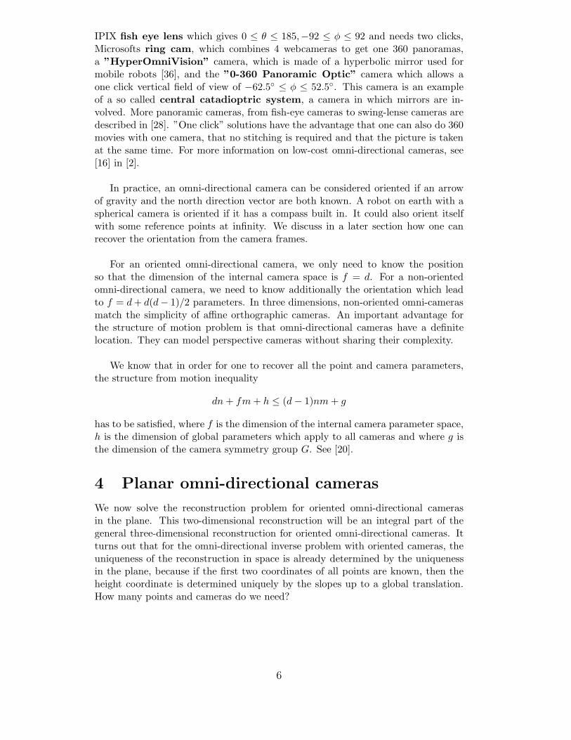
Oriented Omni(d,f,g) = (2,2,3)
Oriented Omni(d,f,g) = (3,3,4)
Figure 1 The forbidden region in the (n,m) plane for oriented omni-directionalcameras. In the plane, (m,n) = (3, 3) is a border line case. In space, (m,n) = (2, 2)is a border line case. For (m,n) outside the forbidden region, the reconstructionproblem is over-determined.
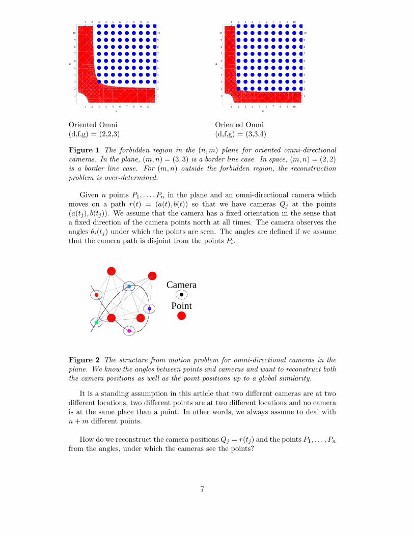
Given n points P1, . . . , Pn in the plane and an omni-directional camera whichmoves on a path r(t) = (a(t), b(t)) so that we have cameras Qj at the points(a(tj), b(tj)). We assume that the camera has a fixed orientation in the sense thata fixed direction of the camera points north at all times. The camera observes theangles θi(tj) under which the points are seen. The angles are defined if we assumethat the camera path is disjoint from the points Pi.
Camera
Point
Figure 2 The structure from motion problem for omni-directional cameras in theplane. We know the angles between points and cameras and want to reconstruct boththe camera positions as well as the point positions up to a global similarity.
It is a standing assumption in this article that two different cameras are at twodifferent locations, two different points are at two different locations and no camerais at the same place than a point. In other words, we always assume to deal withn + m different points.
How do we reconstruct the camera positions Qj = r(tj) and the points P1, . . . , Pn
from the angles, under which the cameras see the points?
7

If Pi = (xi, yi) are the n points and Qj = (a(tj), b(tj)) are the m camera po-sitions, we know the slopes sin(θij)/ cos(θij) if Pi 6= Qj. The linear system of nmequations
sin(θij)(bi − yj) = cos(θij)(ai − xj)
for the 2n variables ai, bi and 2m variables xj, yj allows in general a reconstructionif mn ≥ 2n + 2m. But the reconstruction is not unique: the system of equations isstill homogeneous because scaling and translating of a solution produces a new so-lution. By fixing one point x1 = y1 = 0, the translational symmetry of the problemis broken. By fixing x2 = 1 or the distance between P1 and P2 the scale is fixed.So, if mn ≥ 2n + 2m − 3, we expect a unique solution. If we write the system oflinear equations as Ax = b, then the least square solution is x = (AT A)−1AT b.
For example, in the plane, for n = 3 points and m = 3 cameras, we can alreadyreconstruct both the point and camera positions in the plane in general: there are2n + 3m = (2 · 3) + (2 · 3) = 12 unknowns and 9 equations. The similarity invari-ance fixes 3 variables so that we have the same number of equations than unknowns.
It is important to know when the reconstruction is unique and if the system isoverdetermined, when the least square solution is unique. In a borderline case, thematrix A is a square matrix and uniqueness is equivalent to the invertibility of A.In the overdetermined case, we have a linear system Ax = b. There is a unique leastsquare solution if and only if the matrix A has a trivial kernel.
We call a point-camera configuration ambiguous, if there exists more than onesolution of the inverse problem. The point-camera configuration is ambiguous ifand only if the matrix A has a nontrivial kernel.
For ambiguous configurations, the solution space to the reconstruction is a linearspace of positive dimension. Examples of an ambiguous configuration are collinearconfigurations, where all points as well as the camera path lie on one line. In thatcase, the points seen on the image frames are constant. One can not reconstructthe points nor the camera positions.
If a scale or origin is not specificied, then λPi, λQj would produce a family ofsolutions with the same angular data. We assume to have factored out these sym-metries and do not call this an ambiguity.
We now formulate a fundamental result of circular camera reconstructions in theplane. It gives an answer when m = 3 cameras which have taken pictures of n = 3points, both the camera and the point positions can be obtained uniquely up to asimilarity.
Theorem 4.1 (Structure from motion for omni cameras in the plane I) Ifboth the camera positions as well and the point positions are not collinear and theunion of camera and point positions are not contained in the union of two lines,then the camera pictures uniquely determine the circular camera positions togetherwith the point locations up to a scale and a translation.
8
Even so the actual reconstruction is a problem in linear algebra, this elementaryresult is of pure planimetric nature: we have two non-collinear point sets P,Q whoseunion is not in the union of two lines, then the angles between points in P and Qdetermine the points P,Q up to scale and translation. The result should be seenwith the background of ambiguity results in the plane like Chasles theorem [14]
We call a point or a camera stationary if it can not be deformed withoutchanging the angles between cameras and points. We call it deformable if itcan be deformed without changing angles between cameras and points. If a pointor a camera is deformable, it can move on a line. The reason is that the actualreconstruction problem can be written as a system of linear equations. We call achoice of a one-dimensional deformation space the deformation line of the pointor the camera. If we have an ambiguous camera-point configuration, then thereexists at least one deformable point or camera. The deformation space is a linearspace.
Lemma 4.2 (Triangularization) a) If three non-collinear points P,Q,R are fixed,then each camera C position is determined uniquely from the camera-to-point an-gles.b) If three cameras A,B,C are fixed, then the camera-to-point angles determine eachpoint in the plane uniquely.
Proof. a) If C is not on the line PQ, we know two angles and the length of one sideof the triangle PQC. Similarly for the other lines QR,PR. Because the intersectionof the three lines is empty, every point C is determined.b) Part b) has the same proof. Just switch P,Q,R and A,B,C. 2
Lemma 4.3 (Deformation) a) Every stationary camera must be on the deforma-tion line of a deformable point.b) Every stationary point must be on the deformation line of a deformable camera.
Proof. In both cases, the angles would change if the point would not be on thedeformation line. 2
Now the proof of the theorem.
Proof. By fixing one point P1 and the distance d(P1, P2) = 1 between two points,the scale and translational symmetry is taken care of. Because the point P2 moveslinearly and has to stay within a fixed distance, it is fixed too.
The two stationary points P1, P2 define a line L. By the assumption that thepoints are not collinear, there exists a third point P3 away from that line.
If this point away from the line L were stationary, we would at least three sta-tionary points P1, P2, P3 which are not collinear and by the triangularization lemma,every camera had to be fixed and again by the triangularization lemma, every pointhad to be stationary.
9
So, there is a point P3 away from the line L which can be deformed withoutchanging the angles. Let’s call M the deformation line of P3.
By the deformation lemma, stationary cameras are on M , deformable camerasare on L. Because the set of cameras is not collinear, not all cameras can be on Mand there exists at least one camera Q1 on L. By the two-line assumption, thereexists either a camera or a point away from the two lines. It can not be a stationarypoint P4 because this would give us three fixed points which would fix the scene bythe triangulation lemma.
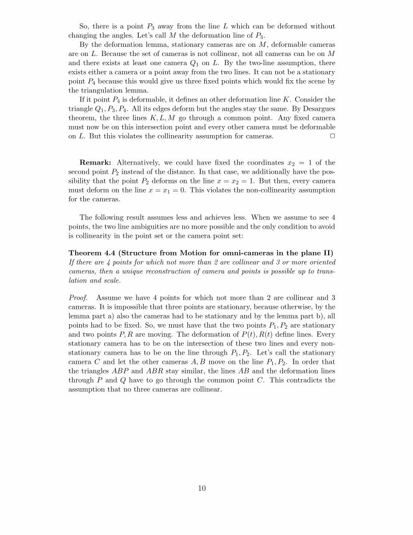
If it point P4 is deformable, it defines an other deformation line K. Consider thetriangle Q1, P3, P4. All its edges deform but the angles stay the same. By Desarguestheorem, the three lines K,L,M go through a common point. Any fixed cameramust now be on this intersection point and every other camera must be deformableon L. But this violates the collinearity assumption for cameras. 2
Remark: Alternatively, we could have fixed the coordinates x2 = 1 of thesecond point P2 instead of the distance. In that case, we additionally have the pos-sibility that the point P2 deforms on the line x = x2 = 1. But then, every cameramust deform on the line x = x1 = 0. This violates the non-collinearity assumptionfor the cameras.
The following result assumes less and achieves less. When we assume to see 4points, the two line ambiguities are no more possible and the only condition to avoidis collinearity in the point set or the camera point set:
Theorem 4.4 (Structure from Motion for omni-cameras in the plane II)If there are 4 points for which not more than 2 are collinear and 3 or more orientedcameras, then a unique reconstruction of camera and points is possible up to trans-lation and scale.
Proof. Assume we have 4 points for which not more than 2 are collinear and 3cameras. It is impossible that three points are stationary, because otherwise, by thelemma part a) also the cameras had to be stationary and by the lemma part b), allpoints had to be fixed. So, we must have that the two points P1, P2 are stationaryand two points P,R are moving. The deformation of P (t), R(t) define lines. Everystationary camera has to be on the intersection of these two lines and every non-stationary camera has to be on the line through P1, P2. Let’s call the stationarycamera C and let the other cameras A,B move on the line P1, P2. In order thatthe triangles ABP and ABR stay similar, the lines AB and the deformation linesthrough P and Q have to go through the common point C. This contradicts theassumption that no three cameras are collinear.
10
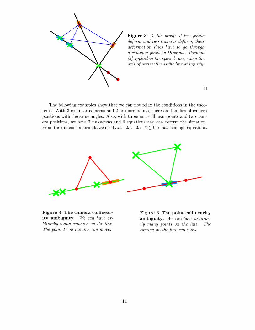
Figure 3 To the proof: if two pointsdeform and two cameras deform, theirdeformation lines have to go througha common point by Desargues theorem[3] applied in the special case, when theaxis of perspective is the line at infinity.
2
The following examples show that we can not relax the conditions in the theo-rems. With 3 collinear cameras and 2 or more points, there are families of camerapositions with the same angles. Also, with three non-collinear points and two cam-era positions, we have 7 unknowns and 6 equations and can deform the situation.From the dimension formula we need nm−2m−2n−3 ≥ 0 to have enough equations.
Figure 4 The camera collinear-ity ambiguity. We can have ar-bitrarily many cameras on the line.The point P on the line can move.
Figure 5 The point collinearityambiguity. We can have arbitrar-ily many points on the line. Thecamera on the line can move.
11

Figure 6 A two line ambiguityI. If cameras and points are con-tained in the union of two lines, it ispossible that a camera point pair canbe deformed without changing cam-era point angles.
Figure 7 A two line ambiguityII. This is an example where a pairof cameras and a point can be de-formed. The configuration is con-tained in the union of two parallellines.
Figure 8 A two camera ambiguity,where one camera can move withoutchanging image data. One can addarbitrarily many more points on theline containing the moving camera.Cameras and points do not need tobe on the union of two lines.
Figure 9 A two point ambiguity.One can add arbitrarily many cam-eras and the union of the point cam-era set does not need to be on theunion of two lines.
Let’s compare the two sides of the dimension formula in the oriented planaromni-directional case (d, f, g) = (2, 2, 3):
12
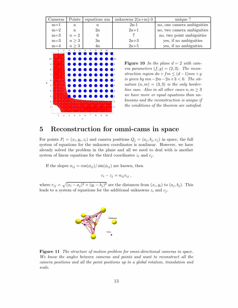
Cameras Points equations nm unknowns 2(n+m)-3 unique ?
m=1 n n 2n-1 no, one camera ambiguitiesm=2 n 2n 2n+1 no, two camera ambiguitiesm=3 n = 2 6 7 no, two point ambiguitiesm=3 n ≥ 3 3n 2n+3 yes, if no ambiguitiesm=4 n ≥ 3 4n 2n+5 yes, if no ambiguities
1 2 3 4 5 6 7 8 9 10
1
2
3
4
5
6
7
8
9
10
1 2 3 4 5 6 7 8 9 10
1
2
3
4
5
6
7
8
9
10
n
m
Figure 10 In the plane d = 2 with cam-era parameters (f, g) = (2, 3). The recon-struction region dn + fm ≤ (d− 1)nm + gis given by mn−2m−2n+3 < 0. The sit-uation (n,m) = (3, 3) is the only border-line case. Also in all other cases n,m ≥ 3we have more or equal equations than un-knowns and the reconstruction is unique ifthe conditions of the theorem are satisfied.
5 Reconstruction for omni-cams in space
For points Pi = (xi, yi, zi) and camera positions Qj = (aj , bj , cj) in space, the fullsystem of equations for the unknown coordinates is nonlinear. However, we havealready solved the problem in the plane and all we need to deal with is anothersystem of linear equations for the third coordinates zi and cj.
If the slopes nij = cos(φij)/ sin(φij) are known, then
ci − zj = nijrij ,
where rij =√
(xi − aj)2 + (yi − bj)2 are the distances from (xi, yi) to (aj , bj). Thisleads to a system of equations for the additional unknowns zi and cj .
Figure 11 The structure of motion problem for omni-directional cameras in space.We know the angles between cameras and points and want to reconstruct all thecamera positions and all the point positions up to a global rotation, translation andscale.
13
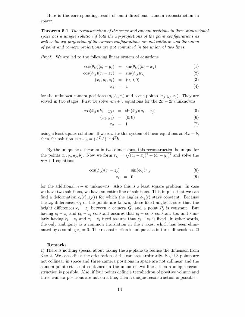
Here is the corresponding result of omni-directional camera reconstruction inspace:
Theorem 5.1 The reconstruction of the scene and camera positions in three-dimensionalspace has a unique solution if both the xy-projections of the point configurations aswell as the xy-projection of the camera configurations are not collinear and the unionof point and camera projections are not contained in the union of two lines.
Proof. We are led to the following linear system of equations
cos(θij)(bi − yj) = sin(θij)(ai − xj) (1)
cos(φij)(ci − zj) = sin(φij)rij (2)
(x1, y1, z1) = (0, 0, 0) (3)
x2 = 1 (4)
for the unknown camera positions (ai, bi, ci) and scene points (xj , yj, zj). They aresolved in two stages. First we solve nm + 3 equations for the 2n + 2m unknowns
cos(θij)(bi − yj) = sin(θij)(ai − xj) (5)
(x1, y1) = (0, 0) (6)
x2 = 1 (7)
using a least square solution. If we rewrite this system of linear equations as Ax = b,then the solution is xmin = (AT A)−1AT b.
By the uniqueness theorem in two dimensions, this reconstruction is unique forthe points xi, yi, aj , bj . Now we form rij =
√
(ai − xj)2 + (bi − yj)2 and solve thenm + 1 equations
cos(φij)(ci − zj) = sin(φij)rij (8)
z1 = 0 (9)
for the additional n + m unknowns. Also this is a least square problem. In casewe have two solutions, we have an entire line of solutions. This implies that we canfind a deformation ci(t), zj(t) for which the angles φij(t) stays constant. Becausethe xy-differences rij of the points are known, these fixed angles assure that theheight differences ci − zj between a camera Qi and a point Pj is constant. Buthaving ci − zj and ck − zj constant assures that ci − ck is constant too and simi-larly having ci − zj and ci − zk fixed assures that zj − zk is fixed. In other words,the only ambiguity is a common translation in the z axes, which has been elimi-nated by assuming z1 = 0. The reconstruction is unique also in three dimensions. 2
Remarks.1) There is nothing special about taking the xy-plane to reduce the dimenson from3 to 2. We can adjust the orientation of the cameras arbitrarily. So, if 3 points arenot collinear in space and three camera positions in space are not collinear and thecamera-point set is not contained in the union of two lines, then a unique recon-struction is possible. Also, if four points define a tetrahedron of positive volume andthree camera positions are not on a line, then a unique reconstruction is possible.
14

2) The result also sheds some light on perspective cameras. Assume we take threepictures of three points and if the camera orientation is identical for all three pic-tures, then we can reconstruct the point and the camera positions up to a scale andtranslation, if both points and cameras are not collinear and the point camera setis not contained in the union of two lines.3) If the union of the camera and point configurations is coplanar, then the ambi-guity examples in 2D apply. If the camera point configurations are not coplanar,then two line ambiguity disappears so that 3 non-collinear camera points and 3 non-collinear scene points which are all not in a common plane determine the situation.4) In real world applications, we don’t see a point at all times, because objectssometimes obscure other objects. Let’s call P the set of points which we can see forsome time interval during the movie and let G be the set of pairs (i, j), for which wecan observe the point Pj at time ti. The pair (P,G) is a graph. If the camera cansee a point for an average fraction r = 2(n+m)/(nm+3) of times, then the systemis expected to have a least square solution. For example, for a movie with m = 10frames observing n = 10 points, then we need to see the points for a fraction of60/200 = 0.3 that is for 30 percent of the times. For m = 100 frames observingn = 1000 points, we need to see an average point less than 2 percent of the timein order to do the reconstruction. A concrete reconstruction would use as manymovie frames as possible for a time interval [a1, b1], then make a new reconstructionfor an other time interval [a2, b2] etc, where [ai, bi] are overlapping intervals on thetime axes. If we look on each interval at the set of points which are visible at alltimes and for these points, the conditions of the theorem are satisfied, then thereconstruction is unique.
The number of cameras can not be reduced in the plane but it can be reducedin space. Two cameras and two points are enough in space in general:
Proposition 5.2 For m = 2 oriented omni-directional cameras in space observingn ≥ 2 points, the point-camera configuration is determined up to scale and Euclideantransformation if the point-camera configuration is not coplanar. The situation isambiguous in two dimensions with 2 cameras for an arbitrary number n of points.
A
B
P
Q
Figure 12 Two oriented omni-directional cameras and two points inthe plane. The angles between camerasand points do not determine the config-uration. Arbitrary many points can beadded. In three dimensions however,two points P,Q and two camerasA,B allow a reconstruction becausethe directions PA,PB,QA,QB ofthe tetrahedron sides determines theshape of the tetrahedron up to a dila-tion and a Euclidean transformation.The 4 points A,B,C,D need to benon-coplanar.
15

6 Structure from motion with moving bodies
We assume now that a omni-directional camera moves through a scene, in which thebodies themselves can change location with time. Examples are a car moving in atraffic lane, a team football players moving on a football field or the earth observingthe planets moving around it. [26]
The reconstruction needs more work in this case, but the problem remains lin-ear if we make a Taylor expansion of each point path. Again the reconstruction isambiguous if we do not fix one body because the entire scene as well as the cameracould move with constant speed and provide alternative solutions. This ambiguityis removed by assuming one point in the scene to have zero velocity.
Assume first that we have a linear motion Pi(t) = Pi + tP ′
i of the points. Thereare now twice as many variables for the points because both positions and velocitiesare unknown.
cos(θij)(bi − yj − tjy′
j) = sin(θij)(ai − xj − tjx′
j) (10)
cos(φij)(ci − zj − tjz′
j) = sin(φij)rij (11)
(x1, y1, z1) = (0, 0, 0) (12)
(x′
1, y′
1, z′
1) = (0, 0, 0) (13)
x2 = 1 (14)
for the unknown camera positions (ai, bi, ci) and scene points (xj , yj, zj) and scenepoint velocities (x′
j , y′
j , z′
j). The nonlinear system can again be reduce to two linearsystems.
This can be generalized to the case when we have a finite Taylor expansion.
Pi(t) =
k∑
l=0
P(l)i tl
for every point. We still have nm equations and a global g dimensional symmetrybut now 3nk + 3mf unknown parameters. If the motion of every point in the sceneis described with a Taylor expansion of the order k, then the structure from motioninequality is
dn(k + 1) + mf ≤ nm(d − 1) + g .
With moving bodies, there can be even more situations, where the motion cannot be reconstructed: take an example with arbitrarily many points, but where twopoints P1(t), P2(t) form a line with the camera position r(t) at all times. In thatcase, we are not able to determine the distance between these two points becausethe points are on top of each other on the movie.
16

Figure 13 The hidden point am-biguity. If one of the points moves sothat it always is behind an other point,we have no information to determinethe distance of the second point fromthe first. There are several point mo-tions which produce the same angulardata.
Instead of a Taylor expansion of the moving bodies, one could also do a Fourierdecomposition of the motion
Pi(t) = Pi +k
∑
l=1
Ail cos(lt) + Bil sin(lt)
and solve for the unknowns Pi, Ail, Bil. Again we are lead to a system of linearequations for which we can look for least square solutions. The dimension formulawould be
dn(2k) + mf ≤ nm(d − 1) + g
7 Non-oriented omni cameras
We have assumed that the omni-directional camera has a fixed ”up” direction andpoints in a fixed direction like ”north” at all times. If an omni-directional cam-era moves in a car, then it can turn. Additionally, the camera could rotate arbi-trarily during the motion. This is described by a curve θ(t), φ(t)). For work onego-motion estimates in omni-directional view, see [12]. Because the additional un-knowns θj = θ(tj), φj = φ(tj) enter in a nonlinear way into the equations, it isbetter to deal with this problem separately. Here is a mean motion algorithmfor computing the camera orientation motion. We assume that the camera motionitself is adiabatic, meaning that the angular motion of the camera is small com-pared with the frame rate. A camera built into an plane or a car would produce anadiabatic camera motion. A non-adiabatic example would be an omni-directionalcamera built into a tennis ball which has been hit with a spin.
1) Compute the angular velocities of all points Pi at the times tj with
ωi(tj) =θi,j+1 − θi,j
tj+1 − tj, ηi(tj) =
φi,j+1 − φi,j
tj+1 − tj.
This is called the motion field.2) Find the average angular velocities
ω(tj) =1
n
n∑
i=1
ωi(tj), η(tj) =1
n
n∑
i=1
cos(ωi(tj))ηi(tj) .
17

This is the mean motion of the optical flow.3) Produce a first approximation of the camera orientation motion
θ(tj) =
j−1∑
l=1
ω(tl), φ(tj) =
j−1∑
k=1
η(tk) .
4) Now fine tune the variables φ(tj), θj individually to minimize the least squaresolution for all j.
Step 4) can be avoided if points are sufficiently far away from the camera. Tocompare it with our own vision capabilities: if we turn our head, then we do steps1-3: we estimate the average speed with which the points around us move. Thisgives us an indication how the head moves.
Remarks. 1) The situation with variable camera orientation could be put intothe framework of the moving bodies. This has the advantage that the system ofequations is still linear. The disadvantage is an explosion of the number of unknownvariables.2) A further refinement of the algorithm to first filter out points which are furtheraway and only average the mean motion of those points. A rough filter is to discardpoints which move with large velocity. See [12] for a Bayesian approach. See also[32].
The problem of ambiguities in the case of unknown camera rotations is morecomplicated also because of the nonlinearity of the problem. Let’s look at thedimensions in the planar case, where each camera located at Qj = (aj , bj) is turnedby an angle θj. We have nm equations
cos(θij − θj)(bi − yj) = sin(θij − θj)(ai − xj)
with (x1 − x2)2 + (y1 − y2)
2 = 1 for the 2n + 2m − 3 + m unknowns
{xi, yi}ni=2, {aj , bj}m
j=1, {θj}mj=1 .
1 2 3 4 5 6 7 8 9 10
1
2
3
4
5
6
7
8
9
10
1 2 3 4 5 6 7 8 9 10
1
2
3
4
5
6
7
8
9
10
n
m
1 2 3 4 5 6 7 8 9 10
1
2
3
4
5
6
7
8
9
10
1 2 3 4 5 6 7 8 9 10
1
2
3
4
5
6
7
8
9
10
n
m
Oriented Omni(d,f,g) = (2,2,3)
Oriented Omni(d,f,g) = (3,3,4)
Figure 14 The forbidden region in the (n,m) plane for oriented omni-directionalcameras.
18

Remarks.1) It seems unexplored, under which conditions the construction is unique for non-oriented omni-cameras. Due to the nonlinearity of the problem, this is certainly isnot as simple as in the oriented case.
2) For omni-directional cameras in space which all point in the same directionbut turn around this axis, the dimension analysis is the same. We can first computethe first two coordinates and then the third coordinate. When going to the affinelimit, these numbers apply to camera pictures for which we know one direction.This is realistic because on earth, we always have a gravitational direction. So, ifwe know the direction of the projection of the z axis onto the picture, then we canreconstruct with 3 pictures and 6 points.
8 Experiments
How does the reconstructed scene depend on measurement or computation errors?How sensible is the least square solution on the entries of A? The error depends onthe volume
√
det(AT A) of the parallelepiped spanned by the columns of A whichform a basis in the image of A. Because this parallelepiped has positive volume ina non-ambiguous situation, we have:
Corollary 8.1 The maximal error ǫ of the reconstruction depends linearly on theerror δ of the angles θij and φij for small δ. There exists a constant C such that|ǫ(δ)| ≤ C|δ|.
Proof. The reconstruction problem is a least square problem Ax = b which hasthe solution x∗ = (AT A)−1AT b. Without error, there exists a unique solution. Ingeneral, A has no kernel if we are not in an ambiguous situation. The error constantdepends on the maximal entries of A and C = 1/det(AT A−1) which are both finiteif A has no kernel. 2
Empirically, we confirm that the maximal error is of the order of δ. We onlymade experiments with synthetic but random data and see that the constant Cis quite small. The computer generated random points, photographs them withan omni-directional cameras from different locations and reconstructs the point lo-cations from the angle data. The maximal error is expected to grow for a largernumber of points because the length of the error vector grows with the dimension.A random vector ~δ = (δ1, . . . , δn) with δi of the order δ has length of the order
√nδ.
0.04
0.08
0.12
0.16
0.2
0.02 0.04 0.06 0.08 0.1
0.12
0.24
0.36
0.48
0.6
0.02 0.04 0.06 0.08 0.1
0.12
0.24
0.36
0.48
0.6
0.02 0.04 0.06 0.08 0.1
19

Figure 15 The maximal error of the reconstruction depends on the error size. Ex-periments with (m,n) = (10, 50), (50, 10), (50, 50). The maximal reconstruction er-ror depends in a linear way on the error added to each coordinate. For every ofthe 30 ǫ values between 0 and 0.1, we do the reconstruction for 10 randomly chosencamera-point configurations and plot for each experiment the maximal deviationamong all the coordinates of all the reconstructed points.
If {ǫi}n+mi=1 are the distances from the n + m original points Pi and cameras
Qj to the reconstructed points and cameras, we have computed the maximal errormax|ǫi|. The mean absolute errors 1
n+m
∑
i |ǫi| the mean errors 1n+m
∑
i ǫi as
well as the root mean errors ( 1n+m
∑
i ǫ2i )
1/2 are much smaller.
Figure 16 The maximal reconstruction error depending on the number 1 ≤ m ≤ 50of cameras and the number 1 ≤ n ≤ 50 of points. The picture shows the same graphfrom two sides. We fixed ǫ = 0.01. For each m and n, the reconstruction was donefor 30 different camera-point worlds. The graph shows the average over these 30samples. For each of the 50 × 50 × 30 experiments, each camera and each point isdisplaced with an independent error of amplitude [−ǫ, ǫ]. The experiment indicatesthat after a sharp decay for small n,m where we have ambiguities, the error growslinearly at most and the change is larger for more cameras than more points.
Remarks:1. The average error decreases like 1/n because the maximal error is essentiallyindependent of n.2. From the practical points of view, we are also interested in how much aberrationwe see when the reconstructed scene is filmed again. Geometrically, the least squaresolution x∗ of the system Ax = b has the property that Ax∗ is the point in theimage of A which is closest to b. If the reconstructed scene is filmed again, theneven with some errors, the camera sees a similar scene. Because A(AT A)−1AT isa projection onto the image of A, this projected error is of the order 1. In otherwords, we see no larger errors than the actual errors.
For refined error estimates for least square solutions see [35, 13].
20

References
[1] C.F. Beautemps-Beaupre. An introduction to the practice of nautical surveyingand the construction of sea charts. London, R.H. Laurie, 1823. Translated fromthe French by Captain Richard Copeland of the Royal Navy.
[2] R. Benosman and S.B. Kang. Panoramic vision. Monographis in ComputerScience. Springer, New York, 2001.
[3] M. Berger. Geometry I. University Text. Springer Verlag, 1987.
[4] Christophewr Burbridge and Libor Spacek. Omnidirectional vision simulationand robot localization. TAROS06, http://cswww.essex.ac.uk/mv/publ.html,2006.
[5] M. Chasles. Question no 296. Nouvelles Annales of Mathematiques, 14:50,Harvard libraries Sci 880.20, 1855.
[6] T. Ehlgen and T. Pajdla. Maneuvering aid for large vehicle using omnidi-rectional cameras. In IEEE Workshop on Applications of Computer Vision(WACV07), 2007.
[7] Oliver Faugeras and Quang-Tuan Luong. The Geometry of Multiple Images.The MIT Press, Cambridge, Massachusetts, London, England, 2001.
[8] Olivier Faugeras. Three-dimensional computer vision: a geometric viewpoint.MIT Press, Cambridge, MA, USA, second edition edition, 1996.
[9] David A. Forsyth and Jean Ponce. Computer Vision: A Modern Approach.Pearson, 2003.
[10] George Francis and Libor Spacek. Linux robot with omnidirectional vi-sion. In Proceedings of TAROS06, 2006. to appear in TAROS06,http://cswww.essex.ac.uk/mv/publ.html.
[11] R. Chellappa G. Quian and Q. Zheng. Robust structure from motion estimationusing inertial data. J. Opt. Soc. Am. A, 18 (12):2982–2997, 2001.
[12] Tarak Gandhi and Mohan M. Trivedi. Parametric ego-motion estimation forvehicle surround analysis using an omnidirectional camera. Mach. Vis. Appl.,16(2):85–95, 2005.
[13] Gene H. Golub and Charles F. Van Loan. An analysis of the total least squaresproblem. SIAM Journal on Numerical Analysis, 17(6):883–893, 1980.
[14] Richard Hartley and Andrew Zissermann. Multiple View Geometry in computerVision. Cambridge University Press, 2003. Second edition.
[15] Richard Capella Hiroshi Ishiguro, Kim C. Ng and Mohan M. Trivedi. Omnidi-rectional image-based modeling: three approaches to approximated plenopticrepresentations. Mach. Vis. Appl., 14(2):94–102, 2003.
[16] H. Ishiguro. Development of low-cost compact omnidirection vision sensors.In Panoramic vision, Monographis in Computer Science. Springer, New York,2001.
[17] T. Kanade and D.D. Morris. Factorization methods for structure from motion.R. Soc. Lond. Philos. Trans. Ser. A Math. Phys. Eng. Sci., 356(1740):1153–1173, 1998. With discussion, New geometric techniques in computer vision(London, 1997).
21
[18] Hiroshi Kawasaki Katsushi Ikeuchi, Masao Sakauchi and Imari Sato. Con-structing virtual cities by using panoramic images. International Journal ofComputer Vision, 58(3):237–247, 2004.
[19] O. Knill and J. Ramirez. On Ullmans theorem in computer vision. 2007.
[20] O. Knill and J. Ramirez. A structure from motion inequality. 2007.
[21] J. Koenderink and A. van Doorn. Affine structure from motion. J. Opt. Soc.Am. A, 8(2):377–385, 1991.
[22] M. Montemerlo and S. Thrun. FastSLAM: A Scalable Method for the Simul-taneous Localization and Mapping Problem in Robotics. Springer Tracts inAdvanced Robotics. Springer, 2007.
[23] American Society of Photogrammetry. Manual of Photogrammetry. AmericanSociety of Photogrammetry, second edition edition, 1952.
[24] S. R. Ortiz. Structure from motion using omni-directional vision and certaintygrids. Thesis at Texas AM University, 2004.
[25] Whitman Richards. Structure from stereo and motion. J. Opt. Soc. Am. A, 2(2):343–349, 1985.
[26] F. Rothganger, Svetlana Lazebnik, Cordelia Schmid, and Jean Ponce. Segment-ing, modeling, and matching video clips containing multiple moving objects.IEEE Transactions on Pattern Analysis & Machine Intelligence, 2006. to ap-pear.
[27] Y. Pritch S. Peleg and M. Ben-Ezra. Omnistereo: panoramic stereo imaging.IEE Transactions on Pattern Analysis and Machine Intelligence, 23, 2001.
[28] David Solomon. Computer graphics and geometric modeling. Springer Verlag,1999.
[29] R. Szeliski and S. B. Kang. Recovering 3D shape and motion from imagestreams using non-linear least squares. Journal of Visual Communication andImage Representation, 5(1):10–28, 1994.
[30] R. Szeliski and Sing Bing Kang. Recovering 3D shape and motion from imagestreams using non-linear least squares. Technical report, Robotics Institute,Carnegie Mellon University, Pittsburgh, PA, March 1993.
[31] Hashem Tamimi, Henrik Andreasson, Andre Treptow, Tom Duckett, and An-dreas Zell. Localization of mobile robots with omnidirectional vision usingparticle filter and iterative sift. In Proceedings of the 2005 European Confer-ence on Mobile Robots (ECMR05), Ancona, Italy, 2005.
[32] Wolfram Burgard Thrun and Dieter Fox. Probabilistic Robotics. MIT Press,2005. first edition.
[33] Emanuele Trucco and Alessandro Verri. Introductory techniques for 3-D com-puter vision. Prentice Hall, New Joersey, 1998.
[34] S. Ullman. The interpretation of visual motion. MIT Press, 1979.
[35] Mu Sheng Wei. The perturbation of consistent least squares problems. LinearAlgebra and its Applications, 112:231–245, 1989.
[36] Yasushi Yagi, Wataru Nishi, Nels Benson, and Masahiku Yachida. Rolling andswaying motion estimation for a mobile robot by using omnidirection obticalflows. Machine Vision and Applications, 14:112–120, 2003.
22
[37] Yasushi Yagi and Masahiko Yachida. Real-time omnidirectional image sensors.International Journal of Computer Vision, 58(3):173–207, 2004.
[38] Masayuki Inaba Yoshio Matsumoto and Hirochika Inoue. View-based naviga-tion using an omniview sequence in a corridor environment. Mach. Vis. Appl.,14(2):121–128, 2003.
23