sp700 product specifications - touch pos · 4.5 self - test print mode 4-33 ... models without an...
TRANSCRIPT

Product Specifications Manual
SP700 Series
Rev. No. 0.14Star Micronics Co., Ltd.
Special Products Operating Division
Contents1. GENERAL DESCRIPTION 1-11.1 Features 1-11.2 Model Name Display Directions 1-22. GENERAL SPECIFICATIONS 2-12.1 Printing Specifications 2-12.2 Character Specifications 2-22.3 NV Logo Specifications 2-52.4 Paper Specifications 2-6
2.4.1 Tear Bar, Auto-cutter Specifications (Only with Horizontal Layout) 2-62.4.2 Take-up Mechanism Specifications 2-7
2.5 Black Mark Specifications 2-82.5.1 Overview of the Black Mark Sensor 2-82.5.2 Dimensions, Positions and Printing Ranges of Black Marks 2-82.5.3 Black Mark PCS Value 2-82.5.4 How to Use TOF 2-8
2.6 Ink Ribbon Specification 2-112.6.1 Specifications 2-112.6.2 Sub-ribbon 2-11 2.6.3 Sub-ribbon Replacement Method 2-11
2.7 Cutting Specification 2-122.7.1 Auto-cutter Specifications (SP742, SP747) 2-122.7.2 Changing from a Partial Cutter to a Full Cutter 2-122.7.3 Auto-cutter Precautions 2-142.7.4 Tear-bar Specifications (SP712, SP717) 2-14
2.8 Take-up Mechanism Specifications (SP712R, SP717R, SP742R, SP747R) 2-142.9 Electrical Specifications 2-14
2.9.1 Power Specification 2-142.9.2 Power Consumption 2-142.9.3 Current Consumption 2-15
2.10 Compatibility Ratings 2-152.11 Reliability Specifications 2-162.12 Environment Specifications 2-16
2.12.1 Ambient Environment 2-16212.2 Storage Environment 2-162.12.3 Vibration Tests (When Packaged) 2-162.12.4 Drop Tests (When Packaged) 2-172.12.5 Static Electricity Tolerance (ESD) 2-172.12.6 AC Line Noise Tolerance 2-17
2.13 Noise 2-172.14 Dust 2-172.15 External Specifications 2-17
2.15.1 Case Specifications 2-172.15.2 Weight 2-172.15.3 External Dimensions 2-18

2.16 How to Set the Roll Paper 2-192.16.1 Tear-bar and Auto-cutter Specifications (SP712, SP717, SP742, SP747) 2-192.16.2 Take-up Mechanism Specifications (SP712R, SP717R, SP742R, SP747R) 2-202.16.3 Mounting the Accessory Roll Paper Guide 2-23
3. CONFIGURATION 3-13.1 Serial interface 3-23.2 Parallel interface 3-83.3 USB 3-133.4 Ethernet 3-133.5 Wireless LAN 3-133.6 External Device Drive Circuit 3-143.7 Options 3-154. FUNCTIONS 4-14.1 Printer Switch Types 4-14.2 DIP Switches 4-14.3 Memory Switches 4-34.4 Operation Switches 4-324.5 Self - test Print Mode 4-334.6 Dot Alignment Adjust Mode 4-344.7 Hexadecimal Dump Mode 4-374.8 Black Mark (BM) Sensor Adjustment Mode 4-384.9 Near-end (NE) Sensor Adjustment Mode (Factory Option). 4-384.10 Memory Switch Manual Setting Mode 4-394.11 Memory Switch Ignore Mode 4-394.12 Errors 4-414.13 Sensors 4-454.14 Printing Rate Determination (SP717/747) 4-455. STAR MODE COMMAND 5-15.1 General Description of Commands 5-16. ESC/POS MODE COMMANDS 6-16.1 General Description of Commands 6-17. CHARACTER CODES 7-17.1 STAR Mode 7-17.2 ESC/POS Mode 7-18. MAINTENANCE 8-19. OTHER PRECAUTIONS 9-19.1 Precautions for Handling 9-19.2 Precautions Concerning Safety 9-110. ACCESSORIES 10-1

1-1
1. GENERALDESCRIPTION
The SP700 series printers are serial impact dot matrix printers used as an electronic device at POS, data recording devices and bank terminal peripheral devices.
1.1 Features 1) Dot Impact Type Receipt Printer The impact method enables printing of copies.
2) Graphics Equipped with a 9 - pin head (SP712/SP742) or an 18 - pin head (SP717/SP747) and a stepping motor
for paper feed drive. The printer is capable of a variety of prints, including graphics and Chinese charac-ters.
3) Logical Seeking Control Equipped with a stepping motor for carriage drive, and corresponds to bidirectional printing using logical
seeking. If using the 18 - pin head model, throughput for printing Chinese characters will be dramatically improved
over the 9 - pin head models.
4) Paper Insertion Employs a drop - in method for easy paper insertion. Ribbon cassette is structured for easy mounting/dismounting.
5) Black Mark Black mark sensor is standard. TOP control enables positioning of the printing position on format paper.
6) Commands Conforms to emulation for both STAR standard commands and ESC/POS system commands.
7) Code Pages Conforms to an abundance of country code pages.
8) There are two types of standard interface models. Models without an interface can use three types of interfaces by combining with the optional interface card.
Serial interface: Conforms to RS - 232C Parallel interface conforms to IEEE 1284 bidirectional parallel interface standards (compatible mode/nib-
ble mode) to handle bidirectional communication. The optional interface card supports USB, Ethernet (cable LAN) and wireless LAN.
9) External device drive circuits The printer employs two drive circuits for drive of peripheral devices, such as cash drawers.
10) Auto - cutter Models: (SP742, SP747, SP742R, SP747R) Both partial and full cuts are possible by changing the mounting position.
11) Models with a take - up mechanism (SP712R, SP717R, SP742R, SP747R)
12) Employs universal power supply Built - in switching type universal power supply
13) Set the following units with options. • Vertical layout unit • Wall - hanging kit • External Buzzer unit

1-2
1.2 ModelNameDisplayDirections
Factory Option: Near-end Sensor
None: No Near-end Sensor (Standard)
Y: Horizontal Layout Near-end Sensor
Z: Vertical Layout Near-end Sensor
Factory Option: Black Mark (Undecided)
SP7 M
H
Country
US/EU/AS/UKCH/JP/TWReserved
Color
None: Standard Color (Off-white)
GRY: GreyTake - up Mechanism
None: No Take-up Mechanism (Standard)
R: With Take-up MechanismInterface types:
C: Parallel Interface
D: Serial Interface
None: Model with No Interface (Supported by Interface Card* See Below)
Paper Feed Method
M: Friction Method + Stepping Motor Method
Mechanism Type
2: 9-pin Head
7: 18-pin Head
Printer Type
1: No Auto-cutter (Has Tear Bar)
4: With Auto-cutter
Interface types:
HU06 : USB
HE06 : Ethernet (10BASE - T/100BASE - TX)
HW04 : Wireless LAN
SP700 Series
* Interface CardI F B D
IFBD Series
-

2-1
2. GENERALSPECIFICATIONS
2.1 PrintingSpecifications
1) Printing Method: Serial dot impact method2) Print Head: 9 pin or 18-pin (wire diameter: 0.3 mm) Has a thermistor3) Printing Direction: Bi - directional/Uni - directional printing4) Printing Speed: Maximum 4.71 lines per second (40 columns of continuous printing for 76 mm paper) Maximum 4.53 lines per second (42 columns of continuous printing for 76 mm paper) Maximum 5.58 lines per second (32 columns of continuous printing for 57.5 mm paper) Maximum 4.90 lines per second (38 columns of continuous printing for 69.5 mm paper)5) Printing Format: 42 positions (76 mm paper, 7 x 9 font, no space between characters) 32 positions (57.5 mm paper, 7 x 9 font, no space between characters)6) Printing Format: Character Configuration 7 (Half) x 9 dots, 5 x 9 dots Character Pitch 1.5 mm (when using 7x 9 fonts) Character Dimensions (See section 2.2. Character Specifications) Dot Spacing 0.30 mm (in the horizontal direction) 0.353 mm (in the vertical direction)7) Total Dot Count: 210 Dots (420 positions) per line8) Printing Width: 63 mm (when using 76 mm paper) 57 mm (when using 69.5 mm paper) 45 mm (when using 57.5 mm paper)9) Paper Feed: Paper Feed Drive Method Friction method using stepping motor drive Paper Feed Pitch: 0.176 mm (1/144 inches) Paper feed time: 39.25 ms (4.23 mm, when line feed is 1/6 inches) Paper Feed Speed Maximum 141 mm per second [5.556 inches/second] (when feeding continuously)10) Printing Region:
76 mm Paper 69.5 mm Paper 57.5 mm Paper
Dot count per line (dpl) 210 200 190 180 160 150
A: Left Margin 6.5 8 6 9.5 3.5 6
B: Printing Region 63 60 57 54 48 45
C: Right Margin 6.5 8 6.5 6.5 6.5 6.5
D: Paper Width 76 76 69.5 69.5 57.5 57.5(mm)
Print Region
A C B
D

2-2
2.2 CharacterSpecifications
1) Character Type and Count
[Standard Specifications]
Character STAR Mode ESC/POS Mode
English Language Characters (ASCII) 95 Characters 95 Characters
Expanded Graphics 128 characters x 40 pages 128 characters x 9 pages
International Characters 46 Characters 37 Characters
[Chinese Specifications]
Character STAR Mode ESC/POS Mode
English Language Characters (ASCII) 95 Characters 95 Characters
Expanded Graphics None 128 Characters ×9 Pages
International Characters 46 Characters 37 Characters
(Chinese Characters) GB18030-2000 (*1) 22013 Characters 22013 Characters
(*1) Only two-byte codes Coded area/Chinese character area: 21887 Characters User defined area: 126 Characters
[Japanese Specifications]
Character STAR Mode ESC/POS Mode
English characters (ASCII) 95 Characters 95 Characters
Expanded Graphics 128 Characters 128 characters x 9 pages
International Characters 46 Characters 37 Characters
(Chinese Characters) JIS First Standard Chinese Characters
3489 Characters 3489 Characters
JIS Second Standard Chinese Characters
3390 Characters 3390 Characters
Special Symbols 83 Characters 83 Characters
Single Byte Characters 282 Characters None
* JIS First and Second Standards conform to JIS X 0208-1990/1997. * Chinese characters support Shift JIS code.
[Taiwan Specifications]
Character STAR Mode ESC/POS Mode
English Language Characters (ASCII) 95 Characters 95 Characters
Expanded Graphics None 128 Characters ×9 Pages
International Characters 46 Characters 37 Characters
(Chinese Characters) BIG5 13710 Characters 13710 Characters

2-3
2) Character Configuration and Sizes (Excluding Space Between Characters)
STAR Mode:
Mode Font TypeDot Configuration
(HxV)Character Size (H x V)
7×9
ANK 7 (Half) x 7 1.2 × 2.42
Block Graphics 9 (Half) x 8 1.5 × 2.77
IBM Graphics 9 (Half) x 12 1.5 × 4.18
5×9 (2P=1)
ANK 5×7 1.5 × 2.42
Block Graphics 6×8 1.8 × 2.77
IBM Graphics 6×12 1.8 × 4.18
5×9 (3P=1)
ANK 5×7 2.1 × 2.42
Block Graphics 6×8 2.55 × 2.77
IBM Graphics 6×12 2.55 × 4.18
Chinese CharacterTwo Byte Chinese Characters 16 (Half) x 16 (Half) 2.55 × 2.95
Single Byte Characters 8 (Half) x 16 (Half) 1.35 × 2.95
ESC/POS Mode:
Mode: Font TypeDot Configuration
(HxV)Character Size (H x V)
7×9ANK 7 (Half) x 7 1.2 × 2.42Block Graphics
9 (Half) x 8 1.5 × 2.77IBM Graphics
5×9ANK 5×7 1.5 × 2.42Block Graphics
6×8 1.8 × 2.77IBM Graphics
Chinese Character Two Byte Chinese Characters 16 (Half) x 16 (Half) 2.55 × 2.95
2-4
3) Character Sets
STAR Mode : Normal (For Overseas Standard/For Japan Domestic) : Katakana : IBM Character Set #1 : Code Page 437 (USA, Standard Europe) (IBM Character Set #2) : Code Page 858 (Multilingual) [*] : Code Page 852 (Latin - 2) : Code Page 860 (Portuguese) : Code Page 861 (Icelandic) : Code Page 863 (Canadian - French) : Code Page 865 (Nordic) : Code Page 866 (Cyllic Russian) : Code Page 855 (Cyllic Bulgarian) [*] : Code Page 857 (Turkish) [*] : Code Page 862 (Hebrew) [*] : Code Page 864 (Arabic) [*] : Code Page 737 (Greek) : Code Page 851 (Greek) : Code Page 869 (Greek) [*] : Code Page 928 (Greek) : Code Page 772 (Lithuanian) : Code Page 774 (Lithuanian) : Code Page 874 (Thai) : Code Page 1252 (Windows Latin -1) [*] : Code Page 1250 (Windows Latin -2) [*] : Code Page 1251 (Windows Cyrillic) [*] : Code Page 3840 (IBM - Russian) : Code Page 3841 (Gost) : Code Page 3843 (Polish) : Code Page 3844 (CS 2) : Code Page 3845 (Hungarian) : Code Page 3846 (Turkish) : Code Page 3847 (Brazil - ABNT) : Code Page 3848 (Brazil - ABICOMP) : Code Page 1001 (Arabic) : Code Page 2001 (Lithuanian - KBL) : Code Page 3001 (Estonian -1) : Code Page 3002 (Estonian -2) : Code Page 3011 (Latvian -1) : Code Page 3012 (Latvian -2) : Code Page 3021 (Bulgarian) : Code Page 3041 (Maltese) : Thai Code Page 42 (Thai) : Thai Code Page 11 (Thai) : Thai Code Page 13 (Thai) : Thai Code Page 14 (Thai) : Thai Code Page 16 (Thai) : Thai Code Page 17 (Thai) : Thai Code Page 18 (Thai)
[*] Handles European characters
* Only normal for character sets in Chinese specification (DBCS) when in STAR mode.

2-5
ESC/POS Mode : Page 0 (PC 437) : Page 1 (Katakana) : Page 2 (PC 858) [*] : Page 3 (PC 860) : Page 4 (PC 863) : Page 5 (PC 865) : Page 16 (PC 1252) : Page 17 (PC 866) : Page 18 (PC 852) : Thai Code Page 42 (Thai) : Thai Code Page 11 (Thai) : Thai Code Page 13 (Thai) : Thai Code Page 14 (Thai) : Thai Code Page 16 (Thai) : Thai Code Page 17 (Thai) : Thai Code Page 18 (Thai) [*] Handles European characters
2.3 NVLogoSpecificationsFunction that stores logo images in the printer’s non-volatile memory and calls one image up for printing using the logo print command. (*)
• Logo memory capacity: 256 K bytes (Data region: 258, 048 bytes) • Maximum number of registered logos: 255
* The NV bit image is the same function.

2-6
2.4 PaperSpecifications2.4.1 TearBar,Auto-cutterSpecifications(OnlywithHorizontalLayout)
Type Regularrollpaper(1ply) *Non-carbonrollpaper(2plyand3ply)
PaperWidthPaperWidth:76±0.5mm(3.0inches);PaperWidth:69.5±0.5mm(2.75inches);PaperWidth:57.5±0.5mm(2.25inches)Take-upWidth:76+1-0.5mm;Take-upWidth:69.5+1-0.5mm;Take-upWidth:57.5+1-0.5mm
Take-upReelDiameter
Max.85mm(3.35inches)
PaperThickness
0.06mmto0.10mm
Two-ply
Original+1copies•Max.totalthicknessof0.14mmcombining0.05to0.08mm(thicknessofonesheet)•Thicknessofuppersheetmustnotbethickerthanthethicknessofthelowersheet.RecommendedPaper:•Types: MitsubishiNCRpapersuper•PaperThickness:UpperpaperN40(paperthickness0.06mm);LowerpaperN60(paperthickness0.08mm)
Three-ply
Original+2copies•Max.totalthicknessof0.2mmcombining0.05to0.08mm(thicknessofonesheet)•Thicknessofuppersheet:t1•Thicknessofmiddlesheet:t2•Thicknessoflowersheet:t3Then:t1≤t2<t3.RecommendedPaper:•Types: MitsubishiNCRpapersuper•PaperThickness:UpperpaperN40(paperthickness0.06mm)
MiddlepaperN40(paperthickness0.06mm)LowerpaperN60(paperthickness0.08mm)
RollCoreDiameter
OuterDiameter:18±1mm;InnerDiameter:12±1mm
Others Paperendsmustnotbegluedortapedtothecoreorfolded.
Notes:(1) Whenusing69.5mmor57.5mmwidthpaper,usetheaccessoryrollpaperguide. Seesection2.13.3RollPaperGuideMountingDiagramfordetailsonmountingtheguide.(2) Seesection2.4BlackMarkSpecificationsfordetailsregardingblackmarkpaper.(3) Paperspecificationswhenusingtheprinterinaverticallayout(includingwall-hanging)
format,thisislimitedtothenormalrollpaperwidth76/69.5mmlistedabove,single-plyandtwo-ply.
(4) WhenusingAuto-cutterspecifications,thespecificationsfortherollpaperarelimitedtonormal,single-plyrollerpaper.
*Onlywithhorizontallayout

2-7
2.4.2 Take-upMechanismSpecificationsType Regular roll paper (1 ply) Non-carbon Roll Paper (Two-ply)
Paper WidthPaper Width: 76 ±0.5 mm (3.0 inches); Paper Width: 69.5±0.5 mm (2.75 inches); Paper Width: 57.5 ±0.5 mm (2.25 inches)
Take-up Width: 76+1 - 0.5 mm; Take-up Width: 69.5+1 - 0.5 mm; Take-up Width: 57.5+1 - 0.5 mmTake - up Reel
Diameter Max. 60 mm (2.36 inches) Max. 85 mm (3.35 inches)
Paper Thick-ness 0.06mm to 0.085mm
Original +1 copies• Max. total thickness of 0.14mm combining 0.05 to 0.08 mm (thickness of one sheet)• Thickness of upper sheet must not be thicker than the thickness of the lower sheet.Recommended Paper:• Types: Mitsubishi NCR paper super• Paper Thickness: Upper paper N40 (pa-per thickness 0.06 mm); Lower paper N60 (paper thickness 0.08 mm)
Roll Core Diameter Outer Diameter: 18 ±1 mm; Inner Diameter: 12 ±1 mm
Others Paper ends must not be glued or taped to the core or folded.

2-8
2.5 BlackMarkSpecifications
2.5.1 OverviewoftheBlackMarkSensorThe SP700 series printers are standardly equipped with one reflective photo-interrupter type sensor for detecting the black mark on the recording paper transport path.This sensor is mounted to a position to detect black marks at the right edge of the printing side (paper feed side) of 76 mm/57.5 mm paper. With a factory option setting, it is possible to mount to two other positions on the printing side, and three positions on the back side, Also, for front side, there are factory option settings for mounting on the paper discharge side. However, this manual does not describe specifications relating to mounting at the paper discharge side.
2.5.2 Dimensions,PositionsandPrintingRangesofBlackMarksSee the figure on the following page for reference regarding the dimensions, positions and printing ranges of black marks.The figure shows a 127 mm black mark pitch.
2.5.3 BlackMarkPCSValueThe PCS value of black marks to be printed should be Min. 0.9.The PCS value of black marks can cause page skipping problems or improper page length detection if they do not meet the aforementioned specifications. This specification must always be observed.
2.5.4 HowtoUseTOFTo achieve a top of form using black marks, always set the memory switch 1-8 to "1."Press the FEED switch to issue the command. Also, by changing the memory switch settings, you can make more details settings for operating conditions, such as selecting TOF when auto-loading paper, the length of the TOF (printing starting position or the cutting position), or selecting TOF when recovering back online (ESC/POS only).For details on the memory switch settings, see section 4.3 Memory Switches.The printing position when executing a TOF differs according to the emulation settings (for STAR, ESC/POS). See the table in section 4.3 Memory Switches.

2-9
<Dimensions, Positions and Printing Ranges of Black Marks>(1) Emulation: STAR Mode
SP712, SP717
SP742, SP747
Note: Itisacceptabletosettheblackmarkpositioninoneplaceoneithersideofthepaper(thesensor’sstandardpositionistherightedgeoftheprintingside).
or
or
(Rec
eipt
Len
gth)
(Def
ault
Val
ue)
(Rec
eipt
Len
gth)
(Def
ault
Val
ue)
Min. 6Min. 6
Min. 6Min. 6
Printing Prohibited Region
Printing Prohibited Region
Printing Region
Tear Bar Cutting Position
Printing Prohibited Region
Auto-cutter Cutting Position
Printing Prohibited Region
Auto-cutter Cutting Position
Tear Bar Cutting Position
Paper Feed
Direction
Printing Region
Paper Feed
Direction

2-10
(2) Emulation: ESC/POS Mode
SP712, SP717
SP742, SP747
Note: 1) Thedimensions*varyaccordingtothesettingsofdimensionsB. 2) Itisacceptabletosettheblackmarkpositioninoneplaceoneithersideofthepaper
(thesensor’sstandardpositionistherightedgeoftheprintingside).
Paper Feed
Direction
or
(Rec
eipt
Len
gth)
(Def
ault
Val
ue)
Min. 6Min. 6
Printing Prohibited Region
Printing Prohibited Region
Printing Region
Tear Bar Cutting Position
Tear Bar Cutting Position
Paper Feed
Direction
(Rec
eipt
Len
gth)
(Def
ault
Val
ue)
Min. 6Min. 6
Printing Prohibited Region
Printing Prohibited Region
Printing Region
or
Auto-cutter Cutting Position
Auto-cutter Cutting Position

2-11
2.6 InkRibbonSpecification
2.6.1 SpecificationsItem Specifications Specifications
Method DedicatedRibbonCassette DedicatedRibbonCassette
Color Red/Black(Standard) Black
RibbonMaterial Nylon66 Nylon66
RibbonDimensions
Width:13mm Width:13mm
NameRed/Black(Standard):RibbonCassette
RC700BRBlack:RibbonCassette
RC700B
LifeBlack:Approx.1.5MillionCharacters(ANK);
Red:Approx.750,000Characters(ANK)Black:Approx.3Million
Characters(ANK)Note: Thereisthepossibilityofproblemssuchasprinterfailuremayoccurifyouusearibbon
cassetteotherthantherecommendedtypes.Suchproblemsarenotunderwarrantee.
2.6.2 Sub-ribbonThis ribbon cassette has a configuration for allowing ribbon replacement. There is a setting for replacement sub-rib-bons.
a) Sub-ribbonSpecifications
Name Sub-ribbonRC700BR Sub-ribbonRC700B
Color Red/Black Black
RibbonMaterial Nylon66 Nylon66
Ribbon Dimensions Width:13mm Width:13mm
LifeBlack:Approx.1.5MillionCharacters(ANK);
Red:Approx.750,000Characters(ANK)Black:Approx.3Million
Characters(ANK)b) Numberofreplacements:Upto5times(Morereplacementsthanthatwillcauseprinterfailureand sothatisprohibited.)
2.6.3 Sub-ribbonReplacementMethod
(1) Removethetopcasehooksatfourlocationsshownbelow,thenremovethetopcase.(2) Removetheusedribbon,andinstallthesub-ribbonalongthepath.(3) Reattachthetopcase.
Note:Withblackribbons,theribbonisintheformofaMöbiussopayattentiontotheinstalla-tionpath.
ExternalViewoftheRibbonCassette
Upper Case Hook
Upper Case Hook
Upper Case
Bottom Case

2-12
2.7 CuttingSpecification2.7.1 Auto-cutterSpecifications(SP742,SP747)
1) Cutting Method: Guillotine 2) Cutting Mode: Supports Partial Cuts (Factory Default Settings)/Full Cuts (1) Partial Cut: Leaves one point uncut in center. However, with using paper widths of 57.5 mm and 69.5 mm, a partial cut leaves one un-cut point 38 mm from the right edge of the paper. (2) Full Cut: By changing the position of the cutter, this changes to full cut specifications. See section 2.6.2 for details on changing the position of the cutter. 3) Cut Duty: 3 seconds/cut Max. 4) Paper Specifications: One sheet; Partial-cut/Full Cut: 65 µm ≤ paper thickness ≤ 100 µm5) Drive Method (Command): See the Control Codes 6) Error Detection: Mechanical sensor detects home position 7) Cutting Position: Paper top edge to cutting position: Distance 19.5 mm
8) Minimum Cutting Length
2.7.2 ChangingfromaPartialCuttertoaFullCutterTo change to full cut specifications, it is necessary to change the cutter installation position. The following outlines how to change the position.
1) Pull the open lever toward yourself to open the rear cover.2) Remove the screws in the drawing with a screwdriver to remove the rear cover.
Min. 3.2 mm
Cutting Position
Head #1 Pin at Cut
Approx. 19.5 mm
Screws (4 Places)
Open Lever
Rear Cover
Print Surface

2-13
3) Use a screwdriver to remove the cutter mounting screws (positions marked P), the move the cutter.
Status of Cutter Unit Partial Cut
(4) Install the cutter unit at the position marked F so that the cutter base boss on the underside and the cutter positioning holes are aligned at the F mark position. (When doing so, mount the screws from the left side.)
(5) Mount the rear cover, then mount the screws you removed.
Cutter Unit Mounting
Screws (Left Side)
Cutter Unit Mounting
Screws (Left Side)
Partial Cut
Positioning Hole
Cutter UnitCutter Unit Mounting
Screws (Right Side)
Positioning Hole
for Full Cut
Cutter Unit Mounting
Screws (Right Side)
2-14
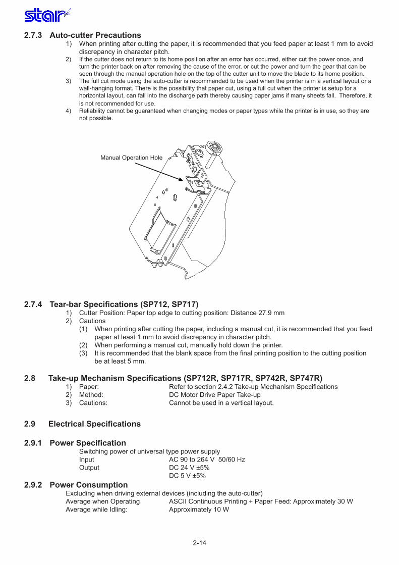
2.7.3 Auto-cutterPrecautions1) When printing after cutting the paper, it is recommended that you feed paper at least 1 mm to avoid discrepancy in character pitch.2) If the cutter does not return to its home position after an error has occurred, either cut the power once, and turn the printer back on after removing the cause of the error, or cut the power and turn the gear that can be seen through the manual operation hole on the top of the cutter unit to move the blade to its home position.3) The full cut mode using the auto-cutter is recommended to be used when the printer is in a vertical layout or a wall-hanging format. There is the possibility that paper cut, using a full cut when the printer is setup for a horizontal layout, can fall into the discharge path thereby causing paper jams if many sheets fall. Therefore, it is not recommended for use.4) Reliability cannot be guaranteed when changing modes or paper types while the printer is in use, so they are not possible.
2.7.4 Tear-barSpecifications(SP712,SP717)1) Cutter Position: Paper top edge to cutting position: Distance 27.9 mm2) Cautions (1) When printing after cutting the paper, including a manual cut, it is recommended that you feed
paper at least 1 mm to avoid discrepancy in character pitch. (2) When performing a manual cut, manually hold down the printer. (3) It is recommended that the blank space from the final printing position to the cutting position
be at least 5 mm.
2.8 Take-upMechanismSpecifications(SP712R,SP717R,SP742R,SP747R)1) Paper: Refer to section 2.4.2 Take-up Mechanism Specifications 2) Method: DC Motor Drive Paper Take-up 3) Cautions: Cannot be used in a vertical layout.
2.9 ElectricalSpecifications
2.9.1 PowerSpecification Switching power of universal type power supply Input AC 90 to 264 V 50/60 Hz Output DC 24 V ±5% DC 5 V ±5%
2.9.2 PowerConsumptionExcluding when driving external devices (including the auto-cutter)Average when Operating ASCII Continuous Printing + Paper Feed: Approximately 30 WAverage while Idling: Approximately 10 W
Manual Operation Hole

2-15
2.9.3 CurrentConsumption Excluding when driving external devices (including the auto-cutter)
Safety Rated Value 1.4A<Standard Parallel/Serial Interface>When power is AC100 V Average when Operating ASCII Continuous Printing + Paper Feed: Approximately 0.53 A Average while Idling: Approximately 0.13 AWhen power is AC120 V Average when Operating ASCII Continuous Printing + Paper Feed: Approximately 0.47 A Average while Idling: Approximately 0.12 AWhen power is AC230 V Average when Operating ASCII Continuous Printing + Paper Feed: Approximately 0.30 A Average while Idling: Approximately 0.10 A
<Model with No Interface + Wireless LAN Interface Card (IFBD-HW04)> When power is AC100 V Average when Operating ASCII Continuous Printing + Paper Feed: Approximately 0.56 A Average while Idling: Approximately 0.16 AWhen power is AC120 V Average when Operating ASCII Continuous Printing + Paper Feed: Approximately 0.50 A Average while Idling: Approximately 0.14 AWhen power is AC230 V Average when Operating ASCII Continuous Printing + Paper Feed: Approximately 0.32 A Average while Idling: Approximately 0.11 A
2.10 CompatibilityRatings1) Europe* CE Marking Emulation EN55022 Class B EN61000 - 3 - 2 EN61000 - 3 -3 Immunity EN55024 EN61000 -4 - 2 EN61000 - 4 - 3 EN61000 - 4 -4 EN61000 - 4 -5 EN61000 - 4 -6 EN61000 - 4 -8 EN61000 - 4 -11EN61000 - 4 -11 Safety Standard (TUV) EN60950 - 1 2001 EN60950 - 1 2001EN60950 - 1 2001 CB Report IEC60950 - 1 20012) North America* Safety Standard (UL, cUL) UL60950 - 1 EMI FCC Part15 Class A
3) Japan EMI VCCI Class A
4) China CCC (Chinese Authorization) GB4943 - 2001, GB9254 - 1998, GB17625.1 - 2003
5) Australia * C-tick (AN/NZS CISPR22 )
6) Russia * GOST
7) Taiwan RPC (CNS13438)
8) Korea MIC (KN22, K00022)
9) Argentina * S mark
10) Mexico * NOM
11) Hong Kong REG.Gap.106Sec.37
* Compatible only with 9-pin head models (SP712, SP742, SP712R, SP742R)

2-16
2.11 ReliabilitySpecifications
1) Life: Mechanical Unit: 10 Million lines (calculated as two lines when printing two pass Chinese characters.) Head: 150 Million Characters Auto - cutter: 1 Sheet: 1 Million Cuts (both full and partial cuts when paper is 65 µm ≤ paper thickness ≤ 100 µm)
* Mechanical parts life is defined as the period at which failures from wear out is entered.
<Conditions>• Printing Operation: Rolling ASCII printing 21 dots in one line.• Paper: General good quality paper (Thickness: 85µm)• Ribbon: Genuine Star RC700B (Black) [Replace ribbon every 3 million characters.]• Auto Cutter: One sheet: General good quality paper (Thickness: 85µm)
2) MCBF: 22 million lines
MCBF is defined as overall failures including accidental failures and failures from part wear out leading to the life of the mechanical parts which is 10 million lines. Mechanical life is 10 million lines. The 22 million lines of MCBF relate to its durability life.
2.12 EnvironmentSpecifications2.12.1AmbientEnvironment
Temperature 0˚C to + 50˚C Humidity: +34˚C 10 to 90% RH (There must be no condensation)
212.2 StorageEnvironmentTemperature -20˚C to + 70˚C Humidity +40˚C 5 to 95% RH (There must be no condensation)
2.12.3VibrationTests(WhenPackaged)
Vibration Frequency 7 to 100 to 7 Hz (Sweep on one side 7.5 minutes)Magnitude: 15.3 to 0.075 to 15.3 mmGravity: 1.5 G ConstantVibration Charged Direction and Time: Three directions of XYZ for one hour. Total: Three hoursPacking Status: Minimum Packing Status
90
80
70
60
50
40
30
20
10
0 0 10 20 30 40 50 [? ]
40˚C, 80%
Operating Environment Range
Fig. 2-4 Operating Temperature and Humidity Range
Relative
Humidity
[%RH]
→ Environment Temperature
34˚C 90%
50˚C, 40%

2-17
2.12.4DropTests(WhenPackaged)Height of Drop: 1 angle; 3 corners from 80cm; 6 surfaces from 1mOrder of Drop: 1 angle; 3 corners; 6 surfacesPacked Status: Minimum Packing Status
2.12.5StaticElectricityTolerance(ESD)Test Specifications
Error Rate: 5% Max. Must be no damage to elements
Direct/Indirect Static Discharge (PC Print) To Outside of Cover
±6 kV ±8 kV
Direct/Atmospheric Discharge (Idling) To Outside of Cover
±8 kV ±15 kV
Indirect Contact Static Discharge (PC Print)
±6 kV ±8 kV
2.12.6ACLineNoiseToleranceTest Specifications
Stand - alone Tolerance (Self - Print) ±1200V
PC Connection Tolerance (ASCII Continuous Printing) ±500V
2.13 NoiseMeasuring Standard: Front side 1 m Conforms to ANSI 1.29When Operating: Approx. 66 dB
2.14 DustThere is no affect on operation in a normal office environment.
2.15 ExternalSpecifications2.15.1CaseSpecifications
Material: ABSColor: Two Models: Off-white/Dark greyFlame - resistance: UL 94 V-0
2.15.2Weight
Tear-bar Types (SP712, SP717) Main Unit: Approximately 2.96 Kg (does not include ribbon)Auto-cutter Types (SP742, SP747) Main Unit: Approximately 3.18 Kg (does not include ribbon)
Take-up Mechanism and Tear-bar Types (SP712R, SP717R) Main Unit: Approximately 3.5 Kg (does not include ribbon)
Take-up Mechanism and Cutter Types (SP742R, SP747R) Main Unit: Approximately 3.7 Kg (does not include ribbon)

2-18
2.15.3ExternalDimensions
Tear-bar, Cutter Types: (SP712, SP717, SP742, SP747) W: Approx. 160 mm x D: Approx. 245 mm x H: Approx. 152 mm
Take-up Mechanism Types: (SP712R, SP717R, SP742R, SP747R) W: Approx. 160 mm x D: Approx. 288 mm x H: Approx. 183 mm
SP712, SP717, SP742, SP747 External View

2-19
SP712R, SP717R, SP742R, SP747R External View
2.16 HowtoSettheRollPaper2.16.1Tear-barandAuto-cutterSpecifications(SP712,SP717,SP742,SP747)
a) Pull the cover open lever in the direction of the Δ (the printer front) to open the printer cover.b) Set the roll paper and check that the paper is over the lever of the paper out switch, then pull the end of the paper toward yourself.c) Close the printer cover.Note:Whenclosingtheprintercover,becarefulthatbothsidesclose.
Open Lever
164 183
288
160
245

2-20
2.16.2Take-upMechanismSpecifications(SP712R,SP717R,SP742R,SP747R)
1. Pull the release lever to open the printer cover and platen arm.
2. Load the paper roll in the direction as shown, and pull approximately 30 cm of the leading edge towards you.
3. Pull the two sheets of the paper roll towards you as shown, and close the platen arm.
Platen Arm
Printer Cover

2-21
4. Push 3 to 4 cm of the leading edge of the bottom sheet through the slit in the spool.
5. Fold the paper roll towards you, over the slit.
6. Wind the paper roll twice around the spool.
Note:Windthepaperrollwithoutlooseningit,whiletherightendofthepaperrollisincontactwiththespoolrim.
7. As you load the spool onto the paper rewinder frame, press the center of the paper roll with your finger so that it won’t unravel from the spool.

2-22
8. Turn the spool gear backward to take up the slack in the paper roll.
Note: Ifthepaperrollhasslackenedduringuse,takeuptheslackinthesamemanner.
9. Close the printer cover as shown, without allowing the top sheet to get caught by the printer cover.
10. Cut the leading edge of the roll paper as shown.
Note:Whenthepaperendmarkappearsonthereverseofthepaper,replacethepaperrollbeforeitrunsout.
• Opening the printer cover before replacing the paper roll
If you open the printer cover before replacing the paper roll, close the platen arm, take up the slack in the paper roll on the spool, and push the paper feed button to feed 5 to 10 cm of paper. Then, perform steps 9 and 10.

2-23
Roll Paper Guide
57.5 mm Width
Paper Groove
69.5 mm Width
Paper Groove
2.16.3MountingtheAccessoryRollPaperGuideWhen using 69.5 mm or 57.5 mm width paper, mount the accessory roll paper guide as described below.
(1) Open the rear cover as described in section 2.13.1.
(2) Fit the accessory roll paper guide into the grooves for 69.5 mm and 57.5 mm paper, as shown below.

3-1
3. CONFIGURATIONSP700MD: Serial interface SP700MC: Parallel interface SP700M: No interface: Optional Interface Cards IFBD - HU06: USB IFBD - HE06: Ethernet (10BASE - T/100BASE - TX) IFBD - HW04 : Wireless LAN

3-2
3.1 Serialinterface1. Specifications Standard: RS - 232C Transmission method: Start - Stop synchronization method Baud Rate: 1200, 2400, 4800, 9600, 19200, 38400 bps (DIPSW (I/F Card) ,MemSW Setting) Data length: 7, 8 bits (DIPSW (I/F Card) Setting) Parity Check: Checks for parity (DIPSW (I/F Card) Setting) Parity Types: Odd/even (DIPSW (I/F Card) Setting) Stop bit: 1 bit (Fixed) Signal polarity: Mark = logic 1 (-3 to -15 V) Space = logic 0 (+3 V to +15 V)

3-3
2) Connector Signal Table
Pin No. Signal Name Direction Function
1 FG - Frame ground
2 TXD OUT Transmission data
3 RXD IN Reception data
4 RTS OUTMemory Switch 4-D is “0” Same as DTR signal
Memory Switch 4-D is “1” Always a space
5 N.C Not Used
6 DSR IN
When DIPSW (I/F Card) 1 – 7 = OFF (1) STAR ModeDoes not check the status of this signal.
(2) ESC/POS Mode• When in DTR/DSR communication modeMemory switch 4-5 = “0”: Checks whether host can receive data as a signal line.
Space status = Host can receive data Mark status = Host cannot receive data
Memory switch 4-5 = “1”: Does not check the status of this signal.• When in X-ON/X-OFF communications, does not check the status of this signal.
When DIPSW (I/F Card) 1 – 7 = ON Becomes an external reset signal.Reset applied by mark status over a pulse width of 1 ms
7 SG Signal ground
8 - 19 N.C Not Used
20 DTR OUT
Indicates whether the printer is ready to receive data from the host.1) When in DTR/DSR communication mode When printer is ready to receive data, a space is applied. When it is not ready, a mark is applied.
Printer StatusMemory Switch 6-90 1
1. Power on or I/F resetTime until communications are ready after reset.
BUSY BUSY
2. Print test, alignment adjustment BUSY BUSY
3. Stop by paper out or paper near end BUSY
4. Other errors BUSY
5. When Reception buffer is full BUSY BUSY
2) When in X-ON, X-OFF Communication Mode Always a space excluding the following conditions. 1. Time until communications are ready and after reset. 2. Print test, alignment adjustment
21 - 24 N.C Not Used
25 INIT
When DIPSW (I/F Card) 1 – 8 = OFF Does not check the status of this signal.
When DIPSW (I/F Card) 1 – 8 = ON Becomes an external reset signal.Reset applied by space status over a pulse width of 1 ms

3-4
3) Communication protocol Communication modes: DTR/DSR mode and X - ON/X - OFF modeNote:Asexplainedbelow,allinterfacesignalnamesrefertotheconnectorpinsontheprinter.
3-1) DTR/DSR Mode OperationsThis mode is selected when the DIPSW (I/F Card) 1 to 6 are turned ON. (Default setting)This mode performs communication while handshaking with the DTR and DSR signals (only when the DSR signal is in ESC/POS mode).In the operations to receive printer data, this mode controls the DTR signals by confirming the BUSY signal. A SPACE indicates that the printer is ready to receive data; conversely, a “MARK” indicates that the printer cannot receive data.
If there is no printer error after turning ON the power, the DTR signal line is set to a SPACE. When the host confirms that the DTR signal line is a SPACE, it sends the data text to the RxD signal line. The printer sets the DTR signal line to a “MARK” after the empty area of the data buffer is below a predeter-mined byte (*1 near buffer full). When the host confirms that the DTR signal line is a MARK, it stops the transmission of data text to the printer buffer, but at this point as well, the printer is still capable of receiv-ing data, up to the amount of empty space in the data buffer. If the host computer ignores the DTR signal and transmits data, all data exceeding the amount of space in the data buffer is simply discarded. The printer sets the DTR signal line to SPACE again when the amount of empty space in the data buffer increased because of the printing and the empty area in the data buffer is a minimum of the fixed num-ber of bytes (*2 near empty conditions). Also, when transmitting printer data status using the DTR/DSR communications mode in the ESC/POS mode, as long as the memory switch 4-5 = 0, data is transmitted after it is confirmed that the host is ready to receive data (DSR signal = SPACE) (excluding the real-time command). Note that when it receives the printer status through an inquiry from the host, the memory switch 6 – 9 (conditions for BUSY) = 1 (only for reception buffer full) should be set so that the DTR signal is applied with a MARK when an error occurs offline. This is not limited to acquiring automatic status.
*1: See section 3-3) Near Buffer Full Conditions for details.*2: See section 3-4) Near Buffer Empty Conditions for details.
<When Online>
DTR
RxD Data Data
Printing
Data
Near Buffer Full Near Buffer Empty
<When Paper Out>
DTR
RxD
Printing
Pout Signal
Paper Out
OnLine OffLine
Data Data
Printing Recovery
Paper In
Cover Close Rear Cover
Cover Open

3-5
3-2) X-ON/X-OFF Mode Operations
This mode is selected when the DIPSW (I/F Card) 1 to 6 are turned OFF. This mode notifies the host of the X-ON data (<DC1>: 11 Hex) when the printer can receive data and the X-OFF data (<DC3>: 13 Hex) when the printer cannot receive data, using the TxD signals.For STAR mode, the X-ON and X-OFF output timing conditions are set by memory switch 4-C.Only 1 byte is output by X-ON when reception not ready changes to reception ready, if the memory switch 4-C is set to 0 (default setting). Only 1 byte is output by the X-OFF when the reception ready changes to reception not ready.Setting the memory switch 4-C to 1, allows the X-ON and X-OFF output to output every 3 seconds.When in the ESC/POS mode, the printer always operates in the same way as when the memory switch 4-C is 0.
If there is no printer error after turning ON the power, the TxD signal line outputs X - ON. After the host receives the X - ON, it sends the data text to the RxD signal line.X-OFF is output when the empty space in the data buffer is a minimum of a fixed number of bytes (*1 near buffer full conditions). The host stops sending data text when it receives the X-OFF, however, the printer is capable of receiving data at that time for the amount of empty space in the data buffer. When memory switch 4-C is set to 1, X-OFF is output for each one byte of data of this status received (near buffer full status) to prevent the reception buffer from overflowing. Data exceeding the amount of empty space overflows the reception buffer and is discarded.The printer outputs X-ON when the amount of empty space in the data buffer increased because of the printing and the empty area in the data buffer is a minimum of the fixed number of bytes (*2 near empty conditions).Note that when it receives the printer status through an inquiry from the host, the memory switch 6 – 9 (conditions for BUSY) = 1 (only for reception buffer full) should be set so that the X-OFF signal is not output when an error occurs offline. This is not limited to acquiring automatic status.
*1: See section 3-3) Near Buffer Full Conditions for details.*2: See section 3-4) Near Buffer Empty Conditions for details.
TxD
Xon
Near Buffer Full Near Buffer Empty
RxD Data Data
Xoff Xoff Xon
Data
Xon
Printing
Pout Signal
Paper Out
Offline Offline
Cover Close
Rear Cover
Printing Recovery
Paper In
Cover Open

3-6
3-3) Near Buffer Full Conditions
Emulation Buffer Size MSW4 - 9 (Big/Small)MSW4 - 9 (Big/Small) Near Buffer Full Conditions (Buffer Empty Area) Remarks
STAR Mode8, 192 bytes When below 256 bytes
256 bytes When below 16 bytes
ESC/POS Mode8, 192 bytes When below 10 bytes
40 bytes When below 10 bytes
3-4) Near Buffer Empty Conditions
Emulation Buffer SizeMSW4 - 9 (Big/Small) Near Buffer Empty Conditions (Buffer Empty Area) (When changed) Remarks
STAR Mode8, 192 bytes When more than 512 bytes256 bytes When more than 156 bytes
ESC/POS Mode8,192 bytes When more than 20 bytes40 bytes When more than 20 bytes

3-7
4) Precautions When Resetting the Printer Using the Interface The printer can be reset from the interface by switching the DIP switches. Switching the Reset
Signal Line DIP Switch Settings Reset Conditions
#6 Pin (DSR) DIPSW (I/F Card) 1 - 7=ON Input of MARK Level
#25 Pin (INIT) DIPSW (I/F Card) 1 - 8=ON Input of SPACE or TTL - HIGH LevelWhen resetting the printer, the following characteristics must be met.
Direct Current Characteristics Direct Current Characteristics of Reset
#6 Pin (DSR) #25 Pin (INIT)
Reset Active Voltage VA - 15V to - 3V +2V to +15V
Reset Negative Voltage VN +3V to +15V - 15V to +0.8V
Reset Active Current IA - 5mA (MAX) +5mA (MAX)
Reset Negative Current IN 5mA (MAX) - 5mA (MAX)
Input Impedance RIN 3KΩ (MIN) Alternating Current Characteristics Reset Minimum Pulse Width TSR 1 msec (MIN)
• When using the #6 pin (DSR) as the reset (DIP Switch (I/F Card) 1-7 = ON)
TRS
H
L
Reset Min. Pulse Width (#6 Pin)
• When using the #25 pin (INIT) as the reset (DIP Switch (I/F Card) 1-8 = ON)
TRS
H
L
Reset Min. Pulse Width (#25 Pin)
Note:Operationsarenotguaranteedwhenasignalthatdoesnotsatisfytheabovecharacteris-ticsisinput.
TheabovecharacteristicsmustbemetinthesamewayaswhenasignalisinputtoINITbyTTL.NotethatifasignalisinputtoDSRbyTTLwiththeabovedirectcurrentcharac-teristics,itwillbeoutsideoftheoperatingguaranteerangeofTTL,andDSRcannotbecontrolled.
•Whenfreeingthe#6pin(DSR)andthe#25pins(INIT),theprinterbecomesoperable.

3-8
3.2 Parallelinterface
This printer conforms to IEEE1284 compatibility mode, and nibble mode as the bi-directional interfaces.
1) Connector signal table for each mode
Pin No. I/O Compatiblity Mode Nibble Mode
1 In nStorobe HostClk
2 In Data0 Data0
3 In Data1 Data1
4 In Data2 Data2
5 In Data3 Data3
6 In Data4 Data4
7 In Data5 Data5
8 In Data6 Data6
9 In Data7 Data7
10 Out nAck PtrClk
11 Out Busy PtrBusy/Data3, 7
12 Out PError AckDataReq/Data2, 6
13 Out Select Xflag/Data1, 5
14 In nAutoFd HostBusy
15 N/C -
16 GND GND
17 Frame GND Frame GND
18 OUT Logic High Logic High
19 GND GND
20 GND GND
21 GND GND
22 GND GND
23 GND GND
24 GND GND
25 GND GND
26 GND GND
27 GND GND
28 GND GND
29 GND GND
30 GND GND
31 In nInit nInit
32 Out nFault nDataAvail/Data0, 4
33 EXT GND -
34 Out Compulsion Status -
35 Out +5V -
36 In nSelectIn 1284Active

3-9
Cautions(1) Initial “n” of signal name indicates a LOW active signal. To communicate bi - directionally, the above signal lines are required.(2) Always use twisted pair lines for each signal line when using the interface and connect the return side to the signal ground level.(3) Precautions when applying a reset to the printer by nInit signal Set the memory switches as shown below for the reset conditions.
MSW6 - E MSW6 - D Reset Conditions
0 0 #31 Pin (nInit) = LOW0 1 Invalid
1 0 #31 Pin (nInit) = LOW & #36 Pin (nSelectIn/1284Active) = LOW1 1 Invalid

3-10
2) Description of the Compatibility Mode
2-1) Specifications The compatibility mode is a mode that is compatible with a conventional Centronix interface. It functions to forward transfer form the host to the printer. • Data transmission method: 8 Bit Parallel • Synchronizing method: According to external nStrobe pulse signal • Handshake: According nAck and Busy signals • Logic level: TTL level compatible
2-2) Description of the Compatibility Mode Interface Timing
T: Min.0.5 µs
T T T
Approx. 9μs
nAck
Data
nStrobe
Busy

3-11
2-3) Description of Signal Line Functions in the Compatibility Mode
Pin No. Signal Name I/OExplanation of Function
When in STAR Mode When in ESC/POS Mode
1 nStrobe InStrobe Pulse for loading data Normally, this is a HIGH level. Data is loaded after it enters a LOW level.
2 to 9 Data 0 to 7 InParallel signal from first to eighth bit of the data.If the data is 1, the level is set to “HIGH”; if the data is 0, the level is set to “LOW”.
10 nAck OutThis signal has an approximately 9 µs pulse width that is issued when loading data.Subsequent data can be received at the point that that pulse signal is completed.
11 Busy Out
DC level signal indicating the printer’s operating status.Subsequent data can be received in LOW level status. When in a HIGH level, it indicates that the printer cannot receive data.(1) When memory switch 6-9 = “0”HIGH when either the reception buffer is near full, or is offline.(2) When memory switch 6-9 = “1”HIGH when the reception buffer is near full.Always HIGH at data entry.
12 PError Out
(1) When memory switch 6-F = “0”HIGH when paper is out.LOW when there is paper.(2) When memory switch 6-F = “1”HIGH at paper out or paper near end LOW when there is paper and is not near end.
The <ESC> “c3” command outputs the status of the selected sensor.
13 Select Out HIGH when online. Always HIGH
14 nAutoFd In Not Used
• When memory switch 3-0 = “1” and 3-1 = “1”Automatic line feed with LOW.Automatic line feed cancelled with HIGH.• Also:
Not Used
15 N/C Not Used
16 GND Signal Ground
17 Frame GND Printer frame ground
18 Logic High 3.9 k pull - up
19 to 30TWISTED
PAIR RETURN
Signal for return for each type of signal. Connected by signal lines corresponding thereto and twisted pair lines.
31 nInit In
To enable a printer external reset using the memory switch settings, a reset is applied by inputting a LOW level higher than 0.5 µs.(Memory switch settings affect the reset conditions.1) See section the precautions for (3) connector signal table for each mode.)
32 nFault Out Enters a LOW level when the printer is not ready to print.
33 EXT GND Ground pins for external connections.
34Compulsion
StatusOut
The status of the compulsion switch signal is output.(See section 3.3 External Device Drive Circuit.)
35 +5V 2.2 k pull - up
36 nSelectIn In Not used (See section the precautions for 1) connector signal table for each mode.)
3-12
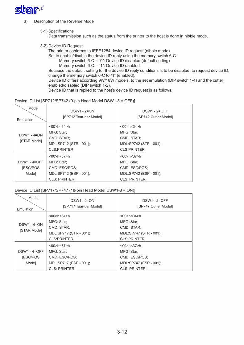
3) Description of the Reverse Mode
3-1) Specifications Data transmission such as the status from the printer to the host is done in nibble mode.
3-2) Device ID Request The printer conforms to IEEE1284 device ID request (nibble mode). Set to enable/disable the device ID reply using the memory switch 6-C. Memory switch 6-C = “0”: Device ID disabled (default setting) Memory switch 6-C = “1”: Device ID enabled Because the default setting for the device ID reply conditions is to be disabled, to request device ID, change the memory switch 6-C to “1” (enabled). Device ID differs according 9W/18W models, to the set emulation (DIP switch 1-4) and the cutter enabled/disabled (DIP switch 1-2). Device ID that is replied to the host’s device ID request is as follows.
Device ID List [SP712/SP742 (9-pin Head Model DSW1-8 = OFF)]
Model
Emulation
DSW1 - 2=ON[SP712 Tear-bar Model]
DSW1 - 2=OFF[SP742 Cutter Model]
DSW1 - 4=ON[STAR Mode]
<00>h<34>hMFG: Star;CMD: STAR;MDL:SP712 (STR - 001);CLS:PRINTER
<00>h<34>hMFG: Star;CMD: STAR;MDL:SP742 (STR - 001);CLS:PRINTER
DSW1 - 4=OFF[ESC/POS
Mode]
<00>h<37>hMFG: Star;CMD: ESC/POS;MDL:SP712 (ESP - 001);CLS: PRINTER;
<00>h<37>hMFG: Star;CMD: ESC/POS;MDL:SP742 (ESP - 001);CLS: PRINTER;
Device ID List [SP717/SP747 (18-pin Head Model DSW1-8 = ON)]
Model
Emulation
DSW1 - 2=ON[SP717 Tear-bar Model]
DSW1 - 2=OFF[SP747 Cutter Model]
DSW1 - 4=ON[STAR Mode]
<00>h<34>hMFG: Star;CMD: STAR;MDL:SP717 (STR - 001);CLS:PRINTER
<00>h<34>hMFG: Star;CMD: STAR;MDL:SP747 (STR - 001);CLS:PRINTER
DSW1 - 4=OFF[ESC/POS
Mode]
<00>h<37>hMFG: Star;CMD: ESC/POS;MDL:SP717 (ESP - 001);CLS: PRINTER;
<00>h<37>hMFG: Star;CMD: ESC/POS;MDL:SP747 (ESP - 001);CLS: PRINTER;

3-13
3.3 USBYou can use a USB interface by installing the USB interface card (IFBD-HU06) in a model without an interface.
1) Specifications: Conforms to USB 2.0 (Full Speed) Refer to the Product Specifications Manual for USB – I/F Card (IFBD-HU05/06) for details on the specifications. 2) Connector: USB Type B
3.4 EthernetYou can use a LAN interface (cable, Ethernet) by installing the Ethernet interface card (IFBD-HE06) in a model without an interface.
1) Specifications: IFBD - HE06 Conforms to IEEE802.3/3u (10BASE-T/100BASE-TX). TCP/IP is the supported protocol. Refer to the Product Specifications Manual IFBD-HE05/06 for details on the specifications. 2) Connector: RJ45 (10BASE - T, 100BASE - TX)
3.5 WirelessLANYou can use a wireless LAN interface by installing the wireless LAN interface card (IFBD-HW04) in a model without an interface.
1) Specifications: Conforms to IEEE802.11b. TCP/IP is the supported protocol. Refer to the Product Specifications Manual IFBD-HW03/04 for details on the specifications.
2) Connector: None

3-14
3.6 ExternalDeviceDriveCircuitThis printer is equipped with an external device (for example, a drive circuit for driving an external buzzer (see section 3.7 Options) or for driving a cash draw). The drive circuit output is mounted with a 6 P module jack connector.
[Drive Circuit]
1) External device 1 and external device 2 cannot be driven simultaneously. Also, duty is under 20%. (Excluding when connecting an external buzzer) 2) When a device other than an external buzzer, such as a cash drawer, is connected, absolute do not use the buzzer drive command <ESC><GS><EM><DC2>. There is the possibility that the connected device and the circuit can be damaged by using that command. 3) Confirming the Compulsion Switch • When in STAR Mode: The status of the compulsion switch can be ascertained by automatic status or the <ENQ> command. When the connector pin No. 6 for the external device drive circuit is HIGH (or is ON), the appropriate status bit is set to “1.” • When in ESC/POS Mode: The setting of the compulsion switch can be ascertained by automatic status or the <DLE> <EOT> n, <ESC> “u” n commands. • When using a parallel interface: Can be ascertained by pin #34 on the parallel interface connector. Pin #34 is a LOW level when the switch is ON. Check using the compatibility mode.4) L1 and L2 are min. 24 Ω5) D1 and D2 Average rectifying current: (Ta = 25°C) IO = 1.0 A Cusp surge current (50 Hz) IFMS = 25 A6) D1866 Absolute Maximum Rating (Ta = 25°C) Collector Current IC = 2 A Collector Loss PC = 1.0 W[Recommended Cable]The table below shows the specifications of the recommended cables.Pin No. 1 (frame ground) is shielded.Modular jack plug model RJ -13 type.
Manufacturers Model
MOLEX 90075 - 007
AMP 641337
FCI B - 66 - 4
6P Modular
Jack Connector
D1866 Circuit Configuration Printer Side External Device Side
With Shield
External Device 1
External
Device 2 Compulsion Switch
Frame Ground
TR1.2: Equivalent to D1866
Drive Output
Modular Jack Plug Shield
Wire Lead Lines

3-15
3.7 Options1) Vertical Layout Unit (VS-S700): Later Mounting Option • If using the printer in a vertical layout, use screws to fasten the paper guide B unit to the printer, and attach rubber stoppers on the backside of the case. Note: Thetake-upmechanismcannotbeused.
2) Wall-hanging Layout Kit (WB-S700): Later Mounting Option • Main unit is set vertically, and mounted to a wall for use. <Precautions> • The take-up mechanism cannot be used.

3-16
4) Buzzer Unit: Later Mounting OptionThe external buzzer unit has a buzzer with the following specifications.
Model Name RMB-24 (Made by Star)
Rated Voltage [V] 24
Operating Voltage Range [V]* 20 to 28
Average Consumption Current [mA] * MAX 21 (TYP21)
Sound Pressure at 1 m ** Min 75 (TYP78)
Response Time [msec] MAX 400
Lead Line Connection (+) Red
(-) Black Note:Itemswithanasterisk(*)arevalueswhenchargingwiththeratedvoltage;Itemswithtwo
asterisks(**)arevalueswhenchargingwiththeminimumoperatingvoltage.
The following shows how to use the external buzzer. (1) Ring the buzzer using the command from the host. Set the buzzer ringing conditions using the command. (2) The memory switch 9 setting will automatically ring the buzzer when specified printer errors occur. Set memory switch 9 for the buzzer ringing conditions. (See the explanation of memory switch 9.)
• Seethecontentsdescribedinsection3.6ExternalDeviceDriveCircuitforprecautionsonhandling.

4-1
4. FUNCTIONS4.1 PrinterSwitchTypesThis printer is set using DIP switches (hardware settings) and memory switches (software settings). Other the function settings, there are the POWER and the FEED switches.There is one 8-bit switch on the main board for the DIP switches (DIPSW 1). When using a serial interface, there also is an 8-bit switch (DIPSW 1 (I/F Card)) on the interface card. The memory switch is stored on the flash memory composed of 1 word 16 bits. It is written by a setting command send from and external source.DIP switches and memory switches settings are loaded when the power is turned on or when the printer is reset. Therefore, when you change the settings, enable them by turning the printer on again, or by executing a hardware reset.
4.2 DIPSwitchesThe following describes the DIP Switch 1 settings on the main PCB.Note that DIP switch settings should be made when the power is turned off.
DIPSW1
DSW Contents ON OFFEx - factory Settings:
SP717 SP747 SP712 SP742
1 - 1 Operating Mode (*1) Normal State Onboard writing ON ON ON ON
1 - 2 Auto – cutter (*2) Invalid Valid ON OFF ON OFF
1 - 3 Boot program writing (*3) Prohibited Allowed ON ON ON ON
1 - 4 Command Emulation STAR ESC/POS ON ON ON ON
1 - 5 USB Mode (Only for USB) Printer Class Vendor Class ON ON ON ON
1 - 6 Two-color Printing Mode (*4) Valid Invalid ON ON ON ON
1 - 7 Reserved: ON ON ON ON
1 - 8 18-pin/9-pin Model Settings (*5) 18-pin Head 9-pin Head ON ON OFF OFF“Only for USB” in the table means that this is valid only when the USB interface card has been installed.
(*2) For the tear bar models (SP712/SP717), a cutter error will occur when the power is turned and the auto-cutter is enabled. Therefore, do not enable the auto-cutter.
(*4) Red/black and white/black inverted commands Two-color Printing Mode “Enabled.” Red/black printing Two-color Printing Mode “Disabled.” White/black inverted printing
(*5) Do not change the default settings. If the actual model and settings do not match, the printer will malfunction.

4-2
When using a serial interface, the printer has DIP switches for setting the communication conditions on the interface card. The settings are shown below.
DIPSW 1 (I/F Card) Serial Interface Card
DSW Contents ON OFFDefault
Settings
1 - 1Baud rates See table below (*1)
ON
1 - 2 ON
1 - 3 Data length 8 Bits 7 Bits ON
1 - 4 Parity Check Invalid Valid ON
1 - 5 Parity Selection Odd Even ON
1 - 6 Handshake: DTR/DSR X - ON/X - OFF ON
1 - 7 #6 Pin (DSR) Reset Signal (*2) Valid Invalid OFF
1 - 8 #25 Pin (INIT) Reset Signal (*2) Valid Invalid OFF
(*1) Baud rate setting table
Memory Switch Serial I/F Dip SwitchBaud Rates
4-1 DSW 1 - 2 DSW 1 - 1
0
ON ON 9600 BPS
ON OFF 4800 BPS
OFF ON 19200 BPS
OFF OFF 38400 BPS
1
ON ON 9600 BPS
ON OFF 2400 BPS
OFF ON 1200 BPS
OFF OFF Reserved
(*2) The setting states of 7 and 8 are not shown in a self-print.

4-3
4.3 MemorySwitches
1) Settings Memory switches are from 0 (MSW 0) to 8 (MSW 9). They are stored in non-volatile memory (flash memory). To change the settings, send the following commands from the host.
[Name] Set memory switch
[Code] ESC GS # m N n1 n2 n3 n4 LF NUL
Hexadecimal 1B 1D 23 m N n1 n2 n3 n4 0A 00
Decimal 27 29 35 m N n1 n2 n3 n4 10 0
[Defined Area] m = “W”, “T”, “, ”, “+”, “ - ”, “@” “0” ≤ N, n1, n2, n3, n4 ≤ “9”, “A” ≤ N, n1, n2, n3, n4 ≤ “F”
[Function] Sends command to write after defining memory switch using the definition command specified by the following classes to set the memory switch. The printer is automatically reset after writing the setting defined By that command to the non - volatile memory. Do not turn off the power to the printer while sending commands to the non - volatile memory. Doing so will destroy the memory switch setting. It is also possible for all memory switch settings to become offset to their initial, default settings. Consider the life of the non - volatile memory and avoid over - sue of this command.
Function Class m N n1 n2 n3 n4
Data Definition (Data Specification) Definition “, ” N n1 n2 n3 n4
Data definition (set specified bit) Definition “+” N n1 n2 n3 n4
Data definition (clear specified bit) Definition “ - ” N n1 n2 n3 n4
Definition data (all data cleared) Definition “@” Fixed at “0” Fixed at “0000”
Definition data write and reset Write “W” Fixed at “0” Fixed at “0000”
Definition data write and reset and test print Write “T” Fixed at “0” Fixed at “0000”
(Ex) Memory switch 1-8 = 0; memory switch 2-7 = 1; memory switch 2-A =1 for a test print:
PRINT #1, CHR$(&H1B);CHR$(&H1D);CHR$(&H23);CHR$(&H2D);CHR$(&H31); ‘ <ESC><GS> # - 1
PRINT #1, CHR$(&H30);CHR$(&H31);CHR$(&H30);CHR$(&H30);CHR$(&H0A);CHR$(0); ‘ 0100 <LF><NUL>
PRINT #1, CHR$(&H1B);CHR$(&H1D);CHR$(&H23);CHR$(&H2B);CHR$(&H32); ‘ <ESC><GS> # + 2
PRINT #1, CHR$(&H30);CHR$(&H34);CHR$(&H38);CHR$(&H30);CHR$(&H0A);CHR$(0); ‘ 0480 <LF><NUL>
PRINT #1, CHR$(&H1B);CHR$(&H1D);CHR$(&H23);CHR$(&H54);CHR$(&H30); ‘ <ESC><GS> # T 0
PRINT #1, CHR$(&H30);CHR$(&H30);CHR$(&H30);CHR$(&H30);CHR$(&H0A);CHR$(&H0); ‘ 0000 <LF><NUL>
4-4
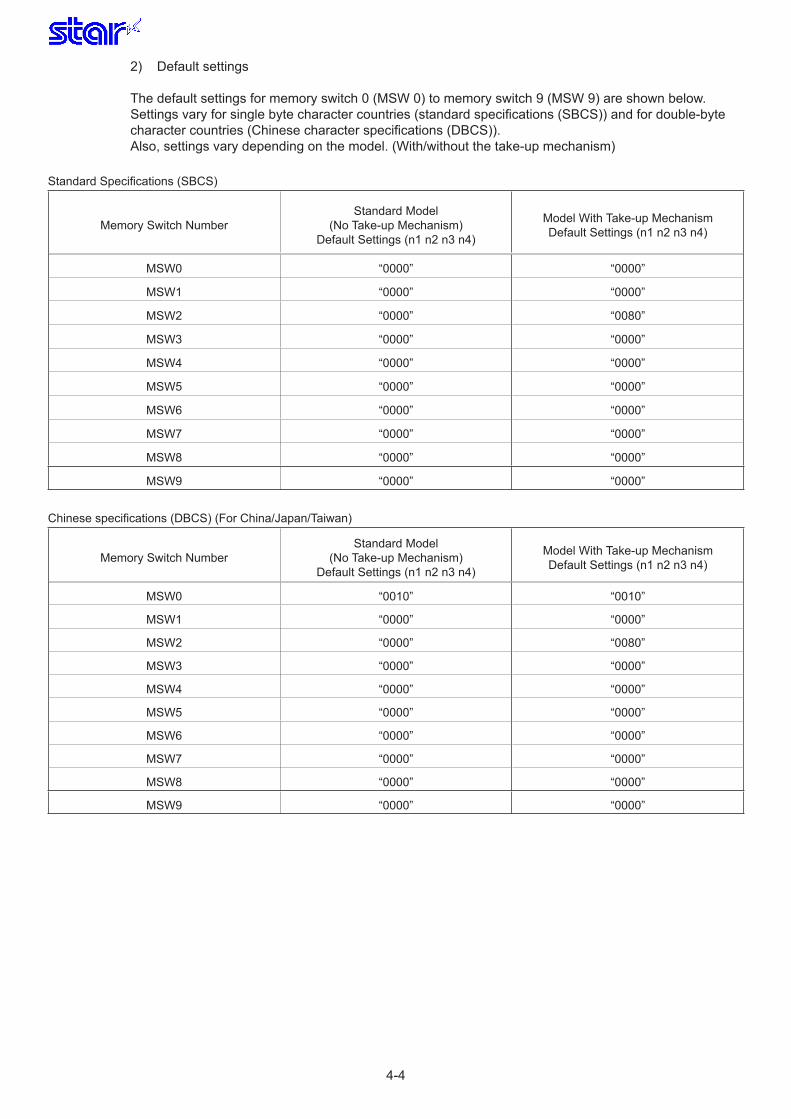
2) Default settings
The default settings for memory switch 0 (MSW 0) to memory switch 9 (MSW 9) are shown below.Settings vary for single byte character countries (standard specifications (SBCS)) and for double-byte character countries (Chinese character specifications (DBCS)). Also, settings vary depending on the model. (With/without the take-up mechanism)
Standard Specifications (SBCS)
Memory Switch NumberStandard Model
(No Take-up Mechanism)Default Settings (n1 n2 n3 n4)
Model With Take-up MechanismDefault Settings (n1 n2 n3 n4)
MSW0 “0000” “0000”
MSW1 “0000” “0000”
MSW2 “0000” “0080”
MSW3 “0000” “0000”
MSW4 “0000” “0000”
MSW5 “0000” “0000”
MSW6 “0000” “0000”
MSW7 “0000” “0000”
MSW8 “0000” “0000”
MSW9 “0000” “0000”
Chinese specifications (DBCS) (For China/Japan/Taiwan)
Memory Switch NumberStandard Model
(No Take-up Mechanism)Default Settings (n1 n2 n3 n4)
Model With Take-up MechanismDefault Settings (n1 n2 n3 n4)
MSW0 “0010” “0010”
MSW1 “0000” “0000”
MSW2 “0000” “0080”
MSW3 “0000” “0000”
MSW4 “0000” “0000”
MSW5 “0000” “0000”
MSW6 “0000” “0000”
MSW7 “0000” “0000”
MSW8 “0000” “0000”
MSW9 “0000” “0000”

4-5
3) FunctionsThe memory switch functions vary for STAR mode and ESC/POS mode. See the descriptions on 2-1) STAR Mode and 2-2) ESC/POS mode.
3-1) When in STAR Mode
3-1-1) Memory Switch 0 (STAR)
Bit Function 0 1
F Reserved
E Chinese Character White/Black Inversion Command See table below (*5) ←
D Chinese Character White/Black Inversion Command See table below (*5) ←
C Chinese Character White/Black Inversion Command See table below (*5) ←
B ANK White/Black Inversion Command See table below (*6) ←
A ANK White/Black Inversion Command See table below (*6) ←
9 ANK Space Character Red/Black Adornment (*7) Adorn Do not adorn
8
7
6
5
4 Country Specifications (*1) SBCS (Single Byte Countries) DBCS (Double Byte Countries)
3 <FF> Command See table below (*2) ←
2 <FF> Command See table below (*2) ←
1 Reserved:
0 Reserved:
(*1) Country SpecificationsCountry MSW0 - 4 = 0 MSW0 - 4 = 1
Overseas (Europe/USA) StandardSpecifications Chinese CharactersChina Standard Specifications ChineseCharactersJapan Standard Specifications JapaneseLanguageChineseCharactersTaiwan Standard Specifications TaiwanCharacters
(*2) <FF> Command Function Selection
MSW0 - 3 MSW0 - 2<FF> Command Function <FF> Command FunctionAuto - cutter Model Tear Bar Model
0 0 Executesaformfeed. Executesaformfeed.
0 1 Executes cut after paper fed to cutting position (*3) Paper is fed to the tear-bar position. (*4)
1 0 Executes a form feed. Executes a form feed.
1 1 Executes cut after paper fed to cutting position (*3) Paper is fed to the tear-bar position. (*4)
(*3) Paper feed amount to cutting position = 1 inch When black mark detection is enabled, paper is fed TOF and to the cutting position.(*4) Paper feed amount to tear bar position = 4/3 inch When black mark detection is enabled, paper is fed TOF and to the cutting position.

4-6
(*5) Chinese Character White/Black Inversion CommandMSW0 - E MSW0 - D MSW0 - C <ESC> “4”/<ESC> “5” Command Functions (Chinese Characters)
0 0 0 Noadornment0 0 1 Settings invalid (no adornment) 0 1 0 <Option 2> Upper line + Underline + enhancing (4 passes)
0 1 1 <Option 3> Upper line + Underline + Double-tall + Enhancing (4 passes)
1 0 0 <Option 4> White/Black Inverted + Double-Tall (2 passes)
1 0 1 <Option 5> White/Black Inverted + 4 X Expanded (2 passes)
1 1 0 Settings invalid (no adornment)
1 1 1 Settings invalid (no adornment) This setting is valid when DIPSW 1-6 = OFF. This function selects adornment means of Chinese Characters in the next white/black inversion com-mand specification, and is compatible with red/black substitute functions on conventional models (SP500). <ESC> ”4” : White/black inverted printing specification (When DIPSW1 - 6=OFF) <ESC> ”5” : Cancel white/black inverted printing (When DIPSW1 - 6=OFF) When using <ESC> “5” to cancel adornments, it returns to the adornments of the previous setting. (Adornments such as underline, upper-line, double-tall expanded and enhancing are cancelled if there is no command to set them (for example the <ESC> “-” 1 specification for underlines).These settings are enabled only on models that support Chinese Characters. This is disabled on ANK character and block character models.
Precautions for selecting Option 2 and Option 3.1. Upper line and underlines are not applied in 90˚ and 270˚ rotated characters.
(*6) ANK White/Black Inversion Command
MSW0 - B MSW0 - A <ESC> “4”/<ESC> “5” Command Functions (ANK)
0 0 White/blackinvertedprinting(1Pass)0 1 <Option 1> White/black inversion (5 x 9 font print) + enhancing (2 passes)1 0 <Option 2> Upper line + Underline + enhancing (2 passes)1 1 <Option 3> Upper line + Underline + Double-tall + Enhancing (4 passes)
This setting is valid when DIPSW 1-6 = OFF. This function selects adornment means of ANK characters in the next white/black inversion command specification, and is compatible with red/black substitute functions on conventional models (SP500). <ESC> ”4” : ANK white/black inverted printing specification (When DIPSW1 - 6=OFF) <ESC> ”5” : Cancel ANK white/black inverted printing specification (When DIPSW1 - 6=OFF) When using <ESC> “5” to cancel adornments, it returns to the adornments of the previous setting. (Adornments such as underline, upper-line, double-tall expanded and enhancing are cancelled if there is no command to set them (for example the <ESC> “-” 1 specification for underlines).This setting is enabled only for ANK characters and block characters. It is disabled for IBM block charac-ters and Chinese characters composed of 12 dot vertical characters (IBM block characters and Chinese characters do not have adornment with this command).
Precautions for selecting Option 1.1. Prints white/black inverted characters using 5 x 9 fonts regardless of the current font size setting.2. Inserts a one dot string of black printing to the head of the white/black inverted characters.3. With 1 and 2 above, the printing position will be off at the right side, and the printable number of characters in one line will be reduced. (For example, to write 42 dots of red print data using a conventional 7 x 9 font, there is a line feed at the 35th dot, and the remaining 7 dots are printed on the next line.)4. Download defined characters defined with 5 x9 fonts are printed regardless of the current font setting (7x9/5x9).5. MSW 3-6 must not be set to 1 (ANK character count = Many). (This will cause a while line to appear between characters.)
Precautions for selecting Option 2 and Option 3.1. Upper line and underlines are not applied in 90˚ and 270˚ rotated characters.

4-7
(*7) ANK Space Character White/Black Adornment This setting selects whether to adorn ANK characters when using white/black inversion, and is compatible with red/black substitute functions on conventional models (SP500). The ANK space characters are limited to ASCII code 20H in this setting. In the character code table, if 7FHex is a space character, 7FHex is a target for this setting. The following is an example of each setting. It is possible to avoid unnecessary adornment in printing patterns that provide spacing of printing positions with ANK space characters (20H) when white/black inversion is specified.
(Print Example) Data: <ESC> “4” “TOTAL” 20H 20H 20H 20H 20H 20H 20H 20H 20H “$1234” <LF>
<Condition 1> ANK adornment (MSW0 - A, 0 - B) = “white/black inverted printing,” ANK space character (MSW0-9) = “adornment”
TOTAL $1234
<Condition 2> ANK adornment (MSW0 - A, 0 - B) = “white/black inverted printing,” ANK space character (MSW0-9) = “no adornment”
TOTAL $1234

4-8
3-1-2) Memory Switch 1 (STAR)
Bit Function 0 1
F Reserved:
E (BM) Operations After Cover Closed (*2) TOF No TOF
D
C (BM) Operations When Power is Turned ON (*3) NoTOF TOF
B ReservedA Reserved9
8 (BM) Black Mark Detection (*1) Invalid Valid
7
6
54 Zero style Normal Slash zero3 International Characters See table below (*4) ←
2 International Characters See table below (*4) ←
1 International CharactersSee table below (*4))
←
0 International Characters See table below (*4) ←
(*1) Operations When Black Mark (BM) Detection is Enabled• <FF> Command executes a TOF to the printing starting position.• <ESC> ‘d' 2 or 3 commands execute a TOF + cut at the cutting position.• Pressing the FEED switch executes a TOF to the printing starting position.• MSW 1-C, and 1-E are applied. Therefore, when MSW 1-8 = 0, MSW 1-C, and 1-E are ignored.• The printing starting position and cutting position can be set by memory switch 7 or by command.
(*2) (BM) Operations After Cover Closed
MSW1 - E Operations After Cover Closed
0(SP712/SP717)TOF
(SP742/SP747+Take-upMechanismDisabled)TOFandCut(SP742/SP747+Take-upMechanismEnabled)TOF
1 No TOFIn this case, TOF means a paper feed to the cutting position.This setting only applies when the MSW 1-8 = 1 (black mark detection enabled).
(*3) In this case, TOF means a paper feed to the cutting position. This setting only applies when the MSW 1-8 = 1 (black mark detection enabled).

4-9
(*4) International Characters Default Value Settings These settings are enabled only on standard specification printers.
MSW1 - 3 MSW1 - 2 MSW1 - 1 MSW1 - 0 International Characters
0 0 0 0 U.S.A0 0 0 1 France0 0 1 0 Germany0 0 1 1 UK0 1 0 0 Denmark 10 1 0 1 Sweden0 1 1 0 Italy0 1 1 1 Spain 11 0 0 0 Japan1 0 0 1 Norway1 0 1 0 Denmark 21 0 1 1 Spain 21 1 0 0 Latin America1 1 0 1 Korea1 1 1 0 Ireland1 1 1 1 Legal
When Code Page 3041 (Maltese) is selected in the character table, international characters are invalid (Character codes that are equivalent to international characters are characters specified by Code Page 3041 (Maltese)).
When MSW 0-4 = “1” (Double-byte countries), this memory switch setting is ignored and the following settings are selected. (Chinese Specifications) USA (Japanese Specifications) Japan (Taiwan Specifications) USA

4-10
3-1-3) Memory Switch 2 (STAR)
Bit Function 0 1F ReservedED ReservedCB Printing Region Width See table below (*1) ←A Paper Width Selection See table below (*1) ←9 Paper Width Selection See table below (*1) ←87 Take - up Mechanism Invalid Valid 6 Reserved543 Contextual Auto-cut Function (*2) Invalid Valid 21 Near End Sensor Function See table below (*3) ←0 Near End Sensor Function See table below (*3) ←
(*1) Print Region Width (MSW 2-B)/Paper Width (MSW 2-A, 2-9) Selection The print region width means the total number of dots in one line.
MSW2 - B MSW2 - A MSW2 - 9 Printing Region Width Paper width
0 0 0 210Dots(63mm) 76mm1 0 0 200 Dots (60mm) 76mm0 0 1 190 Dots (57mm) 69.5mm1 0 1 180 Dots (54mm) 69.5mm0 1 0 160 Dots (48mm) 57.5mm1 1 0 150 Dots (45mm) 57.5mm0 1 1 *1 *11 1 1 *1 *1
(*1) Setting invalid (Rising with the condition of: MSW2 - B="0", 2 - A="0", 2 - 9="0")
(*2) Contextual Auto-cut Function This function cuts paper when a paper feed command that feeds continuously over 7/6 inch. Hosts that cannot send an escape sequence, such as <ESC> "d" 0 can cut paper if a 1/6 inch line feed code <LF> is sent seven times.
(*3) Near End Sensor Function When an optional near end sensor is mounted, settings should abide by those shown in the table below.
MSW2 - 1 MSW2 - 0 Near End Sensor Function
0 0 Invalid0 1 Invalid
1 0 Reflects the near end sensor state to the status.Printing does not stop for near end, and the printer does not go offline.
1 1 Reflects the near end sensor state to the status.Printing does stop for near end, and the printer goes offline.
When enabling the near-end sensor, the sensor should always be mounted.This setting is ignored during a self-print, and alignment adjustment.

4-11
3 - 1 - 4) Memory Switch 3 (STAR)
Bit Function 0 1
F Shift JIS Chinese character mode (On Japanese Models Only) Specification Cancel
E Character Table See table below (*4) ←D Character Table See table below (*4) ←C Character Table See table below (*4) ←B Character Table See table below (*4) ←A Character Table See table below (*4) ←9 Character Table See table below (*4) ←8 Character Table See table below (*4) ←7 Chinese Default Dot Count See table below (*1) ←6 ANK Default Dot Count See table below (*2) ←54321 <CR> Command Functions See table below (*3) ←0 <CR> Command Functions See table below (*3) ←
(*1) Chinese Character Default Dot Count (CPL) Setting For Chinese/Taiwan Character Specifications
MSW3 - 7Paper Width 76 mm Paper Width 69.5mm Paper Width 57.5mm
210 dpl 200 dpl 190 dpl 180 dpl 160 dpl 150 dpl
0 21 20 19 18 16 15
1 23 22 21 20 17 16Paper widths (76/69.5/57.5 mm) and print ranges (210/200/190/180/160/150 dpl) shown in the table are set by the memory switches 2 - 9, 2 - A, and 2 - B.
For Japanese Character Specifications
MSW3 - 7Paper Width 76 mm Paper Width 69.5mm Paper Width 57.5mm
210 dpl 200 dpl 190 dpl 180 dpl 160 dpl 150 dpl
0 23 22 21 20 17 16
1 21 20 19 18 16 15Paper widths (76/69.5/57.5 mm) and print ranges (210/200/190/180/160/150 dpl) shown in the table are set by the memory switches 2 - 9, 2 - A, and 2 - B.
(*2) ANK Default Dot Count (CPL) Setting *1 7×9, *2: 5×9(2P=1), *3: 5×9(3P=1)
MSW3 - 6
Paper Width 76 mm Paper Width 69.5mm Paper Width 57.5mm
210 dpl 200 dpl 190 dpl 180 dpl 160 dpl 150 dpl
*1 *2 *3 *1 *2 *3 *1 *2 *3 *1 *2 *3 *1 *2 *3 *1 *2 *3
0 42 35 23 40 33 22 38 31 21 36 30 20 32 26 17 30 25 16
1 46 38 24 44 36 23 42 34 22 40 32 21 35 29 18 33 27 17Paper widths (76/69.5/57.5 mm) and print ranges (210/200/190/180/160/150 dpl) shown in the table are set by the memory switches 2 - 9, 2 - A, and 2 - B.When MSW 3-6 = 1 the character black/white inversion command should not be used. (This will cause a while line to appear between characters.)

4-12
(*3) <CR> Command FunctionsMSW3 - 1 MSW3 - 0 <CR> Functions
0 0 Ignored
0 1 Ignored
1 0 Prints and performs a line feed (same as <LF>.)
1 1 Prints (No line feed)
(*4) Character Table Settings These settings are enabled only on standard specification printers.
MSW3 - E MSW3 - D MSW3 - C MSW3 - B MSW3 - A MSW3 - 9 MSW3 - 8 Character Table
0 0 0 0 0 0 0 Normal
0 0 0 0 0 0 1 Code Page 437 / IBM Character Set #2
0 0 0 0 0 1 0 Katakana
0 0 0 0 0 1 1 IBM Character Set #1
0 0 0 0 1 0 0 Code Page 858 (Multilingual)
0 0 0 0 1 0 1 Code Page 852 (Latin - 2)
0 0 0 0 1 1 0 Code Page 860 (Portuguese)
0 0 0 0 1 1 1 Code Page 861 (Icelandic)
0 0 0 1 0 0 0 Code Page 863 (Canadian French)
0 0 0 1 0 0 1 Code Page 865 (Nordic)
0 0 0 1 0 1 0 Code Page 866 (Cyrillic Russian)
0 0 0 1 0 1 1 Code Page 855 (Cyrillic Bulgarian)
0 0 0 1 1 0 0 Code Page 857 (Turkish)
0 0 0 1 1 0 1 Code Page 862 (Israel/Hebrew)
0 0 0 1 1 1 0 Code Page 864 (Arabic)
0 0 0 1 1 1 1 Code Page 737 (Greek)
0 0 1 0 0 0 0 Code Page 851 (Greek)
0 0 1 0 0 0 1 Code Page 869 (Greek)
0 0 1 0 0 1 0 Code Page 928 (Greek)
0 0 1 0 0 1 1 Code Page 772 (Lithuanian)
0 0 1 0 1 0 0 Code Page 774 (Lithuanian)
0 0 1 0 1 0 1 Code Page 874 (Thai)
0 1 0 0 0 0 0 Code Page 1252 (Windows Latin - 1)
0 1 0 0 0 0 1 Code Page 1250 (Windows Latin - 2)
0 1 0 0 0 1 0 Code Page 1251 (Windows Cyrillic)
1 0 0 0 0 0 0 Code Page 3840 (IBM - Russian)
1 0 0 0 0 0 1 Code Page 3841 (Gost)
1 0 0 0 0 1 0 Code Page 3843 (Polish)
1 0 0 0 0 1 1 Code Page 3844 (CS2)
1 0 0 0 1 0 0 Code Page 3845 (Hungarian)
1 0 0 0 1 0 1 Code page 3846 (Turkish)
1 0 0 0 1 1 0 Code Page 3847 (Brazil - ABNT)
1 0 0 0 1 1 1 Code Page 3848 (Brazil - ABICOMP)
1 0 0 1 0 0 0 Code Page 1001 (Arabic)
1 0 0 1 0 0 1 Code Page 2001 (Lithuanian - KBL)
1 0 0 1 0 1 0 Code Page 3001 (Estonian - 1)
1 0 0 1 0 1 1 Code Page 3002 (Estonian - 2)
1 0 0 1 1 0 0 Code Page 3011 (Latvian - 1)
1 0 0 1 1 0 1 Code Page 3012 (Latvian - 2)
1 0 0 1 1 1 0 Code Page 3021 (Bulgarian)
1 0 0 1 1 1 1 Code Page 3041 (Maltese)
1 1 0 0 0 0 0 Thai Character Code 42 (Thai)
1 1 0 0 0 0 1 Thai Character Code 11 (Thai)
1 1 0 0 0 1 0 Thai Character Code 13 (Thai)
1 1 0 0 0 1 1 Thai Character Code 14 (Thai)
1 1 0 0 1 0 0 Thai Character Code 16 (Thai)
1 1 0 0 1 0 1 Thai Character Code 17 (Thai)
1 1 0 0 1 1 0 Thai Character Code 18 (Thai)

4-13
When not defied, Normal is selected.When MSW 0-4 = “1” (Double-byte countries), this memory switch setting is ignored and the following settings are selected.(Chinese Specifications) Normal is Fixed(Japanese Specifications) Normal (JP Dedicated) is Fixed(Taiwan Specifications) Normal is Fixed
3 - 1 - 5) Memory Switch 4 (STAR)
Bit Function 0 1
F ReservedED RTS Signal (Serial) SameasDTRsignal Always a spaceC X-ON, X-OFF Output Timing (Serial) OnlyWhenChanged Every 3 secondsBA9 Reception Buffer Size 8,192bytes(Big) 256 bytes (Small)8 Automatic Status Function (*1) Invalid Enabled (Enabled when all status occurs)7 NSB (*1) (*2) Invalid Valid 65 Reserved43 ESC RS a n Command Function OnlySet Automatic Status Sent Only One Time21 Serial Baud Rate Setting Extension Mode (*3) Invalid Valid0 Data Reception Error (Serial) Prints“?” Ignored
(*1) Support for each type of interface is outlined below.
MSW Set Bits Serial ParallelUSB
Printer ClassUSB
Vendor ClassEthernet Wireless LAN
MSW4 - 8 ○ ○×
(Fixed at Disabled)
○×
(Fixed at Enabled)
×(Fixed at Enabled)
MSW4 - 7 - - - ○×
(Fixed at Enabled)
○×
(Fixed at Disabled)
×(Fixed at Disabled)
○: Can be set×: Cannot be set
(*2) NSB Function that returns automatic status each time the reverse rotation mode. This setting is enabled only when using a parallel interface and when in USB vendor class.
(*3) Refer to section 4.2 DIPSW1 (I/F Card) Serial Interface Card for details on serial baud rate settings.
4-14
3 - 1 - 6) Memory Switch 5 (STAR)
Bit Function 0 1
F ReservedE ReservedD ReservedC ReservedB ReservedA Reserved9 Reserved8 Reserved7 Reserved6 Reserved5 Reserved4 Reserved3 Reserved2 Reserved1 Reserved0 Reserved

4-15
3 - 1 - 7) Memory Switch 6 (STAR)
Bit Function 0 1
F nPError Signal (Parallel) Nopaper No paper + near endE nInit Signal Resets Printer (Parallel) See table below (*1) ←D nInit Signal Resets Printer (Parallel) See table below (*1) ←C Device ID Transmission (Parallel) Invalid Valid B Reverse Interrupt Data Handling (Parallel *2) Maintain DiscardedA Reverse Mode (Parallel) Valid Invalid9 BUSY Condition ReceptionbufferorOffline Reception Buffer Full8 Reserved765 Reserved4 Reserved3 Reserved2 Reserved1 Reserved0 Reserved
(*1) Parallel nInit signal reset conditionsMSW6 - E MSW6 - D Reset Conditions
0 0 #31pin (nInit)=LOW0 1 Invalid1 0 #31 pin (nInit) = LOW & #36 pin (nSelectIn/1284Active) = LOW1 1 Invalid
(*2) Reverse Interrupt Data Handling When there is a transition to the forward mode when transferring IEEE1284 reverse data, if the transfer data disappears, set to handle this data. “Maintain”: Maintains lost data and sends it first in the next reverse data transmission. If that data is part way of the automatic status, it sends the remaining portion of the automatic status data. “Discard”: Discards lost data. If that data is part way of the automatic status, it discards the remaining portion of the automatic status data.

4-16
3 - 1 - 8) Memory Switch 7 (STAR)
Bit Function 0 1
FED (BM) Fine Adjustments to the TOF Position (*1)C (BitB to F)(BitB to F)BA98765 (BM) TOF Amount (*2)4 (Bit0 to A)(Bit0 to A)3210
(*1) Fine Adjustments to the TOF Position (Bit B to Bit F)This setting only applies when the black mark detection enabled (MSW 1-8 = “1”).This setting corrects the mechanical differences in stopping position caused by variations in sensor sensitivity.(Correction range: -15 steps to + 15 steps (-2.65 mm to +2.65 mm))Using Bit B, specify whether to correct in the positive or negative directions, and specify the amount of correction using Bit C to Bit F (the LSB on the Bit C side) in 1/144 inch (which equals one step) incre-ments.Default setting is 0.
(Ex: When correction + 10/144 inch)
BitF BitE BitD BitC BitB Fine Adjustment Amount
1 0 1 0 0 +10Step
(Ex: When correction -7/144 inch)BitF BitE BitD BitC BitB Fine Adjustment Amount
0 1 1 1 1 - 7Step
(*2) TOF Amount (Bit 0 to Bit A)This setting only applies when the black mark detection enabled (MSW 1-8 = “1”).Using Bit 0 to Bit A (the LSB on the Bit 0 side) to specify the TOF amount after detection of the black mark (the print-ing starting position and the cutting position) in 1/144 inch (which equals one step) increments. See the following figure (*3) for details on the stopping position when TOF = 0.Setting Range: 0 to 2047/144 inch (max. 361mm)However, the value added with the minute amount of adjustment (Bit B to Bit F) of the TOF position should be less than the distance from a mark and the next mark. (The concept is shown in the drawing.) If the value is higher than the mark distances, the correct TOF will not be attained. Default setting is 0.The TOF can be set using the following commands.This TOF amount is applied as the default value for the printing starting position and the cutting position.
[Setting Command]<ESC><GS>”(””F” pL pH a m nL nH

4-17
(*3) Stopping position of the TOF amount = 0 (default) (MSW1-9 = “0” (When BM sensor installation position = paper feed side))The position to stop in the positions shown in the figure below between the print head #1 pin and the bottom edge of the black mark (the black portion) is the TOF amount 0. When the TOF amount is set, the black mark (the black portion) relatively moves in the upward direction as the reference position.
(1) When using TOF to the Cutting Position (MSW1-9 = “0”)
Model A B
SP742/SP747 Approx. 19.5 mm Approx. 31 mm
SP712/SP717 Approx. 27.9 mm Approx. 31 mm
(2) When using TOF to the Printing Starting Position (MSW1-9 = “0”)
Model B
SP742/SP747 Approx. 31 mm
SP712/SP717 Approx. 31 mm
A
B
ABCDEFG Print Head #1
BM Bottom
Cut Position
Upper Limit of TOF Amount (Concept)
Paper Feed Direction

4-18
3 - 1 - 9) Memory Switch 8 (STAR)
Bit Function 0 1
FEDC ReservedBA98765 Reserved4 Reserved3 Reserved2 Reserved1 Reserved0 Reserved

4-19
3-1-10) Memory Switch 9 (STAR)
Bit Function 0 1
FEDCBA987654
3External Buzzer Ringing Pulse Width (MSW9-0 = “1”)
See table below (*2) ←
2External Buzzer Ringing Pulse Width (MSW9-0 = “1”)
See table below (*2) ←
1External Buzzer Output Destination (MSW9-0 = “1”)
External Device Output 1 External Device Output 2
0 Buzzer Ringing Device at Error (*1) Print Head Buzzer External Buzzer
(*1) The following are errors that can be selected for the output device of the buzzer using this setting. • Paper Out Error • Mechanical Error • Auto-cutter Error Other buzzer ringing operations are fixed to the print head buzzer.
(*2) External Buzzer Ringing Pulse Width The pulse width conditions of this setting are applied to warning sound patterns (*1 above) when MSW9-0 = “1” are described in section 4.12 Errors; 2) Indicators. Set a value higher than the minimum response time for the buzzer you use as a ringing pulse width. Star’s recommended buzzer has a minimum response time of 400 ms, so the default value is set to 400 ms.
MSW9 - 3 MSW9 - 2 Buzzer Ringing Pulse Width
0 0 400ms0 1 600ms1 0 100ms1 1 200ms

4-20
3.-2) When in ESC/POS Mode
3-2-1 Memory Switch 0 (ESC/POS)
Bit Function 0 1
F ReservedE Chinese Character White/Black Inversion Command See table below (*2) ←D Chinese Character White/Black Inversion Command See table below (*2) ←C Chinese Character White/Black Inversion Command See table below (*2) ←B ANK White/Black Inversion Command See table below (*3) ←A ANK White/Black Inversion Command See table below (*3) ←
9 ANK Space Character Adornment Handling (*4) Adorn Do not adorn
87654 Country Specifications (*1) SBCS (Single Byte Countries) DBCS (Double Byte Countries)3 Reserved:2 Reserved:1 Reserved:0 Reserved:
(*1) Country SpecificationsCountry MSW0 - 4 = 0 MSW0 - 4 = 1
Overseas (Europe/USA) StandardSpecifications Chinese CharactersChina Standard Specifications ChineseCharactersJapan Standard Specifications JapaneseLanguageChineseCharactersTaiwan Standard Specifications TaiwanCharacters
(*2) Chinese Character White/Black Inversion Command
MSW0 - E MSW0 - D MSW0 - C <ESC> “r” n Command Functions (Chinese Characters)
0 0 0 Noadornment0 0 1 Settings invalid (no adornment) 0 1 0 <Option 2> Upper line + Underline + Enhancing (4 passes)0 1 1 <Option 3> Upper line + Underline + Double-tall + Enhancing (4 passes)1 0 0 <Option 4> White/Black Inverted + Double-Tall (2 passes)1 0 1 <Option 5> White/Black Inverted + 4 X Expanded (2 passes)1 1 0 Settings invalid (no adornment) 1 1 1 Settings invalid (no adornment)
This setting is valid only when DIPSW 1-6 = OFF. This function selects adornment means of Chinese Characters in the next white/black inversion com-mand specification, and is compatible with red/black substitute functions on conventional models (SP500). <ESC> “r” 1: White/black inverted printing specification (When DIPSW1 - 6=OFF) <ESC> “r” 0: White/black inverted printing specification (When DIPSW1 - 6=OFF) When using <ESC> “r” 0 to cancel adornments, it returns to the adornments of the previous setting. (Adornments such as underline, upper-line, double-tall expanded and enhancing are cancelled if there is no command to set them (for example the <FS> “-“ 1 specification for underlines).These settings are enabled only on models that support Chinese Characters. This is disabled on ANK character and block character models.

4-21
PrecautionsforselectingOption2andOption3.1. Upper line and underlines are not applied in 90˚ and 270˚ rotated characters.
(*3) ANK White/Black Inversion CommandMSW0 - B MSW0 - A <ESC> “r” n Command Functions (ANK)
0 0 White/blackinvertedprinting(1Pass)0 1 <Option 1> White/black inversion (5 x 9 font print) + Enhancing (2 passes)1 0 <Option 2> Upper line + Underline + Enhancing (2 passes)1 1 <Option 3> Upper line + Underline + Double-tall + Enhancing (4 passes)
This setting is valid only when DIPSW 1-6 = OFF. This function selects adornment means of ANK characters in the next white/black inversion command specification, and is compatible with red/black substitute functions on conventional models (SP500). <ESC> “r” 1: White/black inverted printing specification (When DIPSW1 - 6=OFF) <ESC> “r” 0: White/black inverted printing specification (When DIPSW1 - 6=OFF) When using <ESC> “r” 0 to cancel adornments, it returns to the adornments of the previous setting. (Adornments such as underline, double-tall expanded and enhancing are cancelled if there is no com-mand to set them (for example, the <ESC> “-“ 1 specification for underlines).This setting is enabled only for ANK characters and block characters. This is ignored for Chinese char-acters (Chinese characters do not receive adornment with this command).
PrecautionsforselectingOption2andOption3.1. Upper line and underlines are not applied in 90˚ and 270˚ rotated characters.
(*7) ANK Space Character White/Black Adornment This setting selects whether to adorn ANK characters when using red/black adornment, and is compat-ible with red/black substitute functions on conventional models (SP500), in white/black inverted printing. The ANK space characters are limited to ASCII code 20H in this setting. In the character code table, if 7FHex is a space character, 7FHex is a target for this setting. The following is an example of each setting. It is possible to avoid unnecessary adornment in printing patterns that provide spacing of printing positions with ANK space characters (20H) when white/black inversion is specified.
(Print Example) Data: <ESC> “r” 1 “TOTAL” 20H 20H 20H 20H 20H 20H 20H 20H 20H “$1234” <LF>
<Condition 1> ANK adornment (MSW0 - A, 0 - B) = “white/black inverted printing,” ANK space character (MSW0-9) = “adornment”
TOTAL $1234
<Condition 2> ANK adornment (MSW0 - A, 0 - B) = “white/black inverted printing,” ANK space character (MSW0-9) = “no adornment”
TOTAL $1234

4-22
3-2-2) Memory Switch 1 (ESC/POS)
Bit Function 0 1
F ReservedE (BM) Operations After Cover Closed (*2) TOF No TOFDC (BM) Operations When Power is Turned ON (*3) NoTOF TOF
B (BM) Paper Position Correction After a Paper Cut (*4) Valid Invalid
A (BM) Operations When Recovering From a BM Error(*5) TOF No TOF98 (BM) Black Mark Detection (*1) Invalid Valid 7654 Reserved3 Reserved2 Reserved1 Reserved0 Reserved
(*1) Operations When Black Mark (BM) Detection is Enabled • This command executes a TOP to the cutting position. • Pressing the FEED switch executes a TOF to the printing starting position. • MSW 1-A, 1-B, 1-C, and 1-E are applied. Therefore, when MSW 1-8 = 0, MSW 1-A, 1-B, 1-C, and 1-E are ignored. • The printing starting position and cutting position can be set by memory switch 7.
(*2) (BM) Operations After Cover Closed MSW1 - E Operations After Cover Closed
0(SP712/SP717)TOF(SP742/SP747+Take-upMechanismDisabled)TOFandCut(SP742/SP747+Take-upMechanismEnabled)TOF
1 No TOF
In this case, TOF means a paper feed to the cutting position.This setting only applies when the MSW 1-8 = “1” (black mark detection enabled).
(*3) In this case, TOF means a paper feed to the cutting position. This setting only applies when the MSW 1-8 = “1” (black mark detection enabled).
(*4) (BM) Paper Position Correction After a Paper Cut (Only SP742/SP747) MSW 1-B = “0” Correction Enabled: Feeds paper approximately 8 mm after a paper cut. MSW 1-B = “1” Correction Disabled: Does not feed paper after a paper cut. This setting only applies when the MSW 1-8 = “1” (black mark detection enabled).When MSW 1-8 = “0” (black mark detection disabled), correction is always disabled (the printer does not feed paper after a paper cut).
(*5) (BM) TOF Operations When Recovering From a BM Error This setting only applies when the MSW 1-8 = “1” (black mark detection enabled). When using a recovery command from the host to recover back online during a black mark detection error, whether to execute a TOF to the cutting position is a condition for this setting.

4-23
3-2-3) Memory Switch 2 (ESC/POS)
Bit Function 0 1
F ReservedED ReservedCB Printing Region Width See table below (*1) ←A Paper Width Selection See table below (*1) ←9 Paper Width Selection See table below (*1) ←87 Take - up Mechanism Invalid Valid 6 Reserved:543 Reserved:21 Near End Sensor Function See table below (*2) ←0 Near End Sensor Function See table below (*2) ←
(*1) Print Region Width (MSW 2-B)/Paper Width (MSW 2-A, 2-9) Selection The print region width means the total number of dots in one line.
MSW2 - B MSW2 - A MSW2 - 9 Printing Region Width Paper width
0 0 0 200Dots(60mm) 76mm1 0 0 210 Dots (63 mm) 76mm0 0 1 180 Dots (54mm) 69.5mm1 0 1 190 Dots (57mm) 69.5mm0 1 0 150 Dots (45mm) 57.5mm1 1 0 160 Dots (48mm) 57.5mm0 1 1 *1 *11 1 1 *1 *1
*1 • • • Setting invalid (Rising with the condition of: MSW2 - B="0", 2 - A="0", 2 - 9="0")
(*2) Near End Sensor FunctionWhen an optional near end sensor is mounted, settings should abide by those shown in the table below.
MSW2 - 1 MSW2 - 0 Near End Sensor Function
0 0 Invalid0 1 Invalid
1 0 Reflects the near end sensor state to the status.Printing does not stop for near end, and the printer does not go offline.
1 1 Reflects the near end sensor state to the status.Printing does stop for near end, and the printer goes offline.
When enabling the near-end sensor, the sensor should always be mounted.This setting is ignored during a self-print, and alignment adjustment.

4-24
3 - 2 - 4) Memory Switch 3 (ESC/POS)
Bit Function 0 1
F ReservedE ReservedD ReservedC ReservedB ReservedA Reserved9 Reserved8 Reserved7 Chinese Default Dot Count See table below (*1) ←6 ANK Default Dot Count See table below (*2) ←54321 <CR> Command Functions See table below (*3) ←0 <CR> Command Functions See table below (*3) ←
(*1) Chinese Character Default Dot Count (CPL) Setting Chinese, Japanese, and Taiwanese Specifications
MSW3 - 7Paper Width 76 mm Paper Width 69.5mm Paper Width 57.5mm
200 dpl 210 dpl 180 dpl 190 dpl 150 dpl 160 dpl0 22 23 20 21 16 171 20 21 18 19 15 16
Paper widths (76/69.5/57.5 mm) and print ranges (200/210/180/190/150/160 dpl) shown in the table are set by the memory switches 2 - 9, 2 - A, and 2 - B.
(*2) ANK Default Dot Count (CPL) Setting
MSW3 - 6Paper Width 76 mm Paper Width 69.5mm Paper Width 57.5mm
200 dpl 210 dpl 180 dpl 190 dpl 150 dpl 160 dpl7×9 5×9 7×9 5×9 7×9 5×9 7×9 5×9 7×9 5×9 7×9 5×9
0 40 33 42 35 36 30 38 31 30 25 32 261 44 36 46 38 40 32 42 34 33 27 35 29
Paper widths (76/69.5/57.5 mm) and print ranges (200/210/190/180/150/160 dpl) shown in the table are set by the memory switches 2 - 9, 2 - A, and 2 - B.When MSW 3-6 = “1” the character black/white inversion command should not be used. (This will cause a while line to appear between characters.)
(*3) <CR> Command Functions Functions vary according to each interface.
MSW3 - 1 MSW3 - 0<CR> Functions
Parallel interfaceSerial Interface, USB, Ethernet, Wireless LAN
0 0 Prints (No line feed) Prints (No line feed)0 1 Prints and performs a line feed (same as <LF>.) Prints and performs a line feed (same as <LF>.)
1 0
Prints and obeys the Auto Fd signal.(1) When AutoFd = LowPerforms a line feed (same as <LF>.)
(2) When AutoFd = HighNo line feed.
Ignored
1 1 Ignored Ignored

4-25
3 - 2 - 5) Memory Switch 4 (ESC/POS)
Bit Function 0 1
F Automatic Status Types for USB ESC/POSStatus STAR StatusED RTS Signal (Serial) SameasDTRsignal Always a spaceC ReservedBA9 Reception Buffer Size 8,192bytes(Big) 40 bytes (Small)8 Automatic Status Function(*1) Invalid Enabled (Same as <GS> “a” 2)7 Reserved 6
5 DSR check when transmitting status (serial) Yes No
43 Reserved 21 Serial Baud Rate Setting Extension Mode (*2) Invalid Valid0 Data Reception Error (Serial) Prints“?” Ignored
(*1) Support for each type of interface is outlined below.
MSW Set Bits Serial Parallel USBPrinter Class
USBVendor Class
Ethernet Wireless LAN
MSW4 - 8 ○ ○ ×(Fixed at Disabled)
○ ×(Fixed at Enabled)
×(Fixed at Enabled)
○: Can be set×: Cannot be set
(*2) Refer to section 4.2 DIPSW1 (I/F Card) Serial Interface Card for details on serial baud rate settings.

4-26
3 - 2 - 6) Memory Switch 5 (ESC/POS)
Bit Function 0 1
F Reserved E Reserved D Reserved C Reserved B Reserved A Reserved 9 Reserved 8 Reserved 7 Reserved 6 Reserved 5 Reserved 4 Reserved 3 Reserved 2 Reserved 1 Reserved 0 Reserved

4-27
3 - 2 - 7) Memory Switch 6 (ESC/POS)
Bit Function 0 1
F Reserved E nInit Signal Resets Printer (Parallel) See table below (*1) ←D nInit Signal Resets Printer (Parallel) See table below (*1) ←C Device ID Transmission (Parallel) Invalid Valid B Reserved A Reverse Mode (Parallel) Valid Invalid9 BUSY Condition ReceptionbufferorOffline Reception Buffer Full8 Reserved 765 Reserved 4 Reserved 3 Reserved 2 Reserved 1 Reserved 0 Reserved
(*1) Parallel nInit signal reset conditionsMSW6 - E MSW6 - D Reset Conditions
0 0 #31Pin(nInit)=LOW0 1 Invalid1 0 #31 Pin (nInit) = LOW & #36 Pin (nSelectIn/1284Active) = LOW1 1 Invalid

4-28
3 - 2 - 8) Memory Switch 7 (ESC/POS)
Bit Function 0 1
FED (BM) Fine Adjustments to the TOF Position (*1)C (BitB to F)(BitB to F)BA98765 (BM) TOF Amount (*2)4 (Bit0 to A)(Bit0 to A)3210
(*1) Fine Adjustments to the TOF Position (Bit B to Bit F)This setting only applies when the black mark detection enabled (MSW 1-8 = “1”).This setting corrects the mechanical differences in stopping position caused by variations in sensor sensitivity.(Correction range: -15 steps to + 15 steps (-2.65 mm to +2.65 mm))Using Bit B, specify whether to correct in the positive or negative directions, and specify the amount of correction using Bit C to Bit F (the LSB on the Bit C side) in 1/144 inch (which equals one step) incre-ments. Default setting is 0.
(Ex: When correction + 10/144 inch)
BitF BitE BitD BitC BitB Fine Adjustment Amount
1 0 1 0 0 +10Step
(Ex: When correction -7/144 inch)
BitF BitE BitD BitC BitB Fine Adjustment Amount
0 1 1 1 1 - 7Step
(*2) TOF Amount (Bit 0 to Bit A)This setting only applies when the black mark detection enabled (MSW 1-8 = “1”).Using Bit 0 to Bit A (the LSB on the Bit 0 side) to specify the TOF amount after detection of the black mark (the printing starting position and the cutting position) in 1/144 inch (which equals one step) incre-ments.See the following figure (*3) for details on the stopping position when TOF = 0.Setting Range: 0 to 2047/144 inch (max. 361mm)However, the value added with the minute amount of adjustment (Bit B to Bit F) of the TOF position should be less than the distance from a mark and the next mark. (The concept is shown in the drawing.) If the value is higher than the mark distances, the correct TOF will not be attained. Default setting is 0.

4-29
(*3) Stopping position of the TOF amount = 0 (default) (MSW1-9 = “0” (When BM sensor installation position = paper feed side))The position to stop in the positions shown in the figure below between the print head #1 pin and the bottom edge of the black mark (the black portion) is the TOF amount 0. When the TOF amount is set, the printing starting position moves in the downward direction using this position as its reference.
(1) When using TOF to the Cutting Position (MSW1-9 = “0”)
Model A B
SP742/SP747 (MSW1 - B=”0” : Printing position correction after a paper cut) Approx. 14 mm Approx. 13.1 mm
SP742/SP747 (MSW1 - B=”1” : No printing position correction after a paper cut) Approx. 14 mm Approx. 5.5 mm
SP712/SP717 Approx. 27.9 mm Approx. 5.5 mm
(2) When using TOF to the Printing Starting Position (MSW1-9 = “0”)
Model B
SP742/SP747 Approx. 5.5 mm
SP712/SP717 Approx. 5.5 mm
ABCDEFG Print Head #1
BM Bottom
Cut Position
Paper Feed Direction
TOF Amount Upper Limit (Concept)
B
A

4-30
3 - 2 - 9) Memory Switch 8 (ESC/POS)
Bit Function 0 1
FEDC Cutter Position Correction Function (*2) Invalid Valid BA98765 Reserved4 Reserved3 Reserved2 Reserved1 Reserved0 Reserved
(*2) On models equipped with an auto-cutter perform the following operations when using the cut com-mand. (1) 7.6 mm paper reverse feed(2) Executes a paper cut (3) 7.6 mm paper forward feedThe commands applied with this function are shown below. <ESC> "m", <ESC>"i", <GS> "V" n (n=0, 1, 48, 49)
The printing results of the distance from the print head’s first pin position to the cutting position when us-ing this function are shown below. Cutter Position Correction “Disabled”: 19.5 mmCutter Position Correction “Enabled”: 27.1 mm

4-31
3-2-10) Memory Switch 9 (ESC/POS)
Bit Function 0 1
FEDCBA9876543 External Buzzer Ringing Pulse Width (MSW9-0 = “1”) See table below (*2) ←2 External Buzzer Ringing Pulse Width (MSW9-0 = “1”) See table below (*2) ←1 External Buzzer Output Destination (MSW9-0 = “1”) External Device Output 1 External Device Output 2 0 Buzzer Ringing Device at Error (*1) Print Head Buzzer External Buzzer
(*1) The following are errors that can be selected for the output device of the buzzer using this setting. • Paper Out Error• Mechanical Error• Auto-cutter ErrorOther buzzer ringing operations are fixed to the print head buzzer.
(*2) External Buzzer Ringing Pulse Width The pulse width conditions of this setting are applied to warning sound patterns (*1 above) when MSW9-0 = “1” are described in section 4.12 Errors; 2) Indicators. Set a value higher than the minimum response time for the buzzer you use as a ringing pulse width. Star’s recommended buzzer has a minimum response time of 400 ms, so the default value is set to 400 ms.
MSW9 - 3 MSW9 - 2 Buzzer Ringing Pulse Width
0 0 400ms0 1 600ms1 0 100ms1 1 200ms

4-32
4.4 OperationSwitches
1) POWER Switch The POWER switch turns the power source on and off to supply power to the printer. Turn the power on and off when the printer is connected with a power cable.
2) FEED Switch Type: Tact Switch (A non-locking push switch) Function: When pressed, executes a 1/6 inch paper feed. If pressed continuously, paper is continuously fed. In that situation, the FEED switch will not feed paper. 1. Adjustment mode such as print test 2. Mechanical errors, cutter errors, non-recoverable errors The printer will enter any of the following adjustment modes by turning on the power to the printer while holding down the FEED switch.
<How to Enter Each Adjustment Mode>
Turn the power on while holding down the FEED switch. The printer will enter each adjustment mode depending on when you release the switch.
(1) Release the switch after the buzzer beeps one time. This enters the self-print mode of 4.5.
↓ (After holding for two seconds)
(2) Release the switch after the buzzer beeps twice. This enters the dot alignment adjustment mode of 4.6.
↓ (After holding for two seconds)
(3) Release the switch after the buzzer beeps three times. This enters the hexadecimal dump mode of 4.7.
↓ (After holding for two seconds)
(4) Release the switch after the buzzer beeps four times. This enters the black mark sensor adjustment mode of 4.8.
↓ (After holding for two seconds)(5) Release the switch after the buzzer beeps five times. This enters the near-end sensor adjustment mode of 4.9 (factory option).
↓ (After holding for two seconds)
(6) Release the switch after the buzzer beeps six times. This enters the memory switch manual setting mode of 4.10.
↓ (After holding for two seconds)
(7) Release the switch after the buzzer beeps seven times. This enters the memory switch ignore mode of 4.11.
↓ (After holding for two seconds)
Returns to (1).
3) Rear Cover Open Switch Type: Mechanical switch Function: Detects when the rear cover is open.
4) Front Cover Open Switch Type: Mechanical switch Function: Detects when the front cover is open.

4-33
4.5 Self-testPrintMode
1) Procedures for Self - test Print Turn the POWER switch on while holding down the FEED switch. When the buzzer beeps one time, release the FEED switch to enter the self-test print mode. The self-test print mode prints each of the printer’s settings and ASCII characters onto the paper. On Chinese character models, it continues by printing Chinese characters. The contents printed for the printer’s settings vary according to the emulation settings for the DIP switches, so perform the self - test print after setting to the emulation conditions that are actually used.
2) Items to Check in the Self - test Print Mode (1) Firmware version (2) Interface card type (3) Memory switch settings (4) DIP switch settings (5) Dot correction setting number (6) Types of Chinese character fonts installed (7) Boot program version (8) Print quality check using an ASCII print (9) Print quality using Chinese character print (When Ethernet or a wireless LAN card is installed on models without an interface, Chinese characters are output in a short pattern (only for one block of an upper code). ) (10) Network settings (only when Ethernet or a wireless LAN card is installed on models without an interface)
3) Continuing and ending self - test printing Continue pressing the FEED switch to continue printing a continuous print pattern after printing of an ASCII pattern is completed. If you release the FEED switch, the self - test print mode will quit after the print pattern is completed. After the self - test print is quit, the printer will automatically reset itself to its normal status. After the self-test print is quit, the printer will automatically reset itself to its normal status. When the cover is open, close it to continue.

4-34
4.6 DotAlignmentAdjustMode
1) General Description This mode functions to adjust the amount of discrepancy of the dots in uni-directional (right to left) and reciprocal directions (left to right), in 1/8 dot increments. Settings are stored in a non - volatile memory so they are maintained after the power is turned off.2) Setting Procedures (1) Turn the POWER switch on while holding down the FEED switch. When the buzzer beeps two times, release the FEED switch to enter the dot position adjustment mode. When the printer has entered the dot alignment adjust mode, it prints the message ‘Dot Alignment Adjust Mode’ on standard, Chinese, and Taiwanese specifications models. When the paper is out while printing, this mode is automatically exited. Ensure that there is enough paper. (2) Then, the dot adjustment patter is printed while shifting 1/8 dots per line, as shown below, to print 22 patterns. Guide numbers 1 to 23 and settings (Lvl. ) are printed above each line. The line that has an asterisk (*) is the current printer setting.

4-35
(3) As shown in the drawing below, the adjustment pattern prints three dots in an outward and return pass (for a total of six dots), and prints a vertical line in the middle composed of three dots. Determine that the vertical line printed as the straightest to be the optimum correction. An operator can visually determine by looking at the print results to adjust the pattern to the smallest amount of discrepancy in the dots in one direction and in reciprocal directions. To do so, press the FEED switch for guide number (1 to 23) of the best pattern. (The printer will give a short beep (0.13 seconds) each time the FEED switch is pressed.)When doing so, when you get to the number of times that corresponds to the desired line number, continue to press the FEED switch (approximately 2 seconds) to set the new value. The buzzer will beep for approximately 0.5 seconds. For example, to set to number four, quickly press the FEED switch 3 times, then press the FEED switch slightly longer on the fourth time (until the buzzer beeps). Note that if you press the FEED switch more than more than 24 times, you will have exceeded the possible range of settings. The buzzer will beep repeatedly. The number of times you pressed the FEED switch will be cleared, so you must redo the settings (3) from the beginning.
(4) If there is no pattern that matches the printed patterns, use the “Backward” (*1) or the “Forward” (*2) operations guided in the first of the guide numbers to reprint the print pattern with the changed dot adjustment and repeat the third step.
(*1) Backward Press the FEED switch from two to four seconds for “Backward.” (The buzzer will ring.) → A corrected pattern with the reciprocated pass more toward the left than the currently displayed pattern, or with the outward pass more to the right than the currently displayed pattern is displayed.
(*2) Forward Press the FEED switch for four seconds for “Forward.” (The buzzer will ring.) → A corrected pattern with the reciprocated pass more toward the right than the currently displayed pattern, or with the outward pass more to the left than the currently displayed pattern is displayed.
(5) After the printer writes the determined settings to the non-volatile memory, the printer prints the newly determined settings in a pattern, then two patterns before and after for a total of five patterns to notify the operator of the new settings. It then prints a message to indicate the setting has been completed (*1). (*1) In standard, Chinese, and Taiwanese specification models “Adjust Completed!” is printed and an asterisk (*) is appended to the newly set pattern. The following shows an example of the printout.
Incorrect Optimum Incorrect

4-36
<Precautions>The operator must absolutely not turn OFF the power or reset the printer in the time between determin-ing the settings (#3 above) and the start of the printout above. If the power is turned off while the printer is writing to the non-volatile memory, all memory switch setting data, not only the dot alignment settings, will be damaged, and everything will be returned to their default settings.
If you mistake the settings, do not turn off the power. Wait for the final reset to apply, then redo the set-ting from the beginning.
(6) The buzzer will ring once for a longer time (0.5 seconds), and the printer will be automatically reset, thereby exiting this mode.

4-37
4.7 HexadecimalDumpMode
1) General Description This mode allows you to check the actual data being transmitted from the host by printing the data send from the host in hexadecimal format and the characters corresponding thereto.
2) Hexadecimal Dump Procedures Turn the POWER switch on while holding down the FEED switch. When the buzzer beeps three times, release the FEED switch to enter the hexadecimal dump mode. When the printer enters the hexadecimal dump mode, the printer prints “//// Hexadecimal Dump ////.” For paper widths of 76 mm, the printer prints the hexadecimal code on the left-hand side and the corresponding characters on the right-hand side. For paper widths of 57.5 mm, the printer prints the hexadecimal code on the first line, and the corresponding characters on the second line. For codes for which the data is not ASCII characters (20H to 7FH), the printer outputs a period (.) for characters. Note that commands do not function while the printer is in the hexadecimal dump mode.
Also, if print data does not fill one line, the printer reception buffer will keep that data without printing it. If that occurs, press the FEED switch once to cause the printer to print that data. For that reason, the operator should press the FEED switch after quitting the entire dump so that the no output is overlooked.
3) Quitting the Hexadecimal Dump Turn the POWER switch off.

4-38
4.8 BlackMark(BM)SensorAdjustmentMode
1) Adjustment Procedures (1) Set the paper (so that the white portion of the paper is at the black mark sensor), then turn the POWER switch ON. (2) Press the FEED switch five times to feed the paper. (This is to remove any slack or skewing of the paper.) (3) Turn the POWER switch OFF. (4) Turn the POWER switch ON while holding down the FEED switch. When the buzzer beeps four times, release the FEED switch to enter the BM sensor adjustment mode. (5) Adjust the VR2 by rotating it clockwise. Adjust so that only the POWER LED (green) or the ERROR LED (red) lights. (6) Turn the VR2 again to adjust so that both the POWER and ERROR LEDs light.
When adjusting at (5) so that the POWER LED (green) lights, turn VR2 to the clockwise direction. When adjusting at (5) so that the ERROR LED (green) lights, turn VR2 to the counterclockwise direction. If it is not possible to find the position where both LEDS light, the sensor is malfunctioning. (7) If you set the printer vertically to adjust VR, check that both LEDs did not change when you return the printer to its normal state.
2) Quit adjustment mode Turn the POWER switch off or press the FEED switch to exit the mode.
4.9 Near-end(NE)SensorAdjustmentMode(FactoryOption).
1) Adjustment Procedures (1) Set the paper so that it is at the NE sensor. (2) Turn the POWER switch on while holding down the FEED switch. When the buzzer beeps five times, release the FEED switch to enter the NE sensor adjustment mode. (3) Adjust the VR1 by rotating it until both the POWER LED (green) and the ERROR LED (red) light. If both LEDs are lit, adjustments are unnecessary. (4) If you set the printer vertically to adjust VR, check that both LEDs did not change when you return the printer to its normal state.
2) Quit adjustment mode Turn the POWER switch off or press the FEED switch to exit the mode.

4-39
4.10 MemorySwitchManualSettingMode
1) Setting Procedures (1) Turn the POWER switch on while holding down the FEED switch. When the buzzer beeps six times, release the FEED switch to enter the memory switch manual setting mode. (2) Determine the memory switch number. After pressing the FEED switch for the amount of times as the memory number, press the FEED switch until the buzzer rings (for approximately 2 seconds.) For example, if the memory switch number is 2, press the FEED switch two times (the buzzer will ring for 0.13 seconds each time the switch is pressed) and the buzzer will ring. Release the switch once, then press the FEED switch for a long time (after the buzzer rings for approx. 0.13 seconds, it will ring for a longer time of approximately 0.5 seconds). If the memory switch number is 0, simply press the FEED switch for a long time (until the buzzer rings for a long time). (3) Determine the bit number. After pressing the FEED switch for the amount of times as the bit number, press the FEED switch until the buzzer rings (for approximately 2 seconds.) For example, if the memory switch number is A, press the FEED switch 10 times (the buzzer will ring each time the switch is pressed) and the buzzer will ring. Release the switch once, then press the FEED switch for a long time (after the buzzer rings for approx. 0.13 seconds, it will ring for a longer time of approximately 0.5 seconds). If the bit switch number is 0, simply press the FEED switch for a long time (until the buzzer rings). (4) The printer shows the current 0/1 settings using the following LEDs. Status “0”: Power LED (Green) = extinguished; Error LED (Red) = lit Status “1”: Power LED (Green) = lit; Error LED (Red) = extinguished (5) The status of 0/1 changes (the LED display is also interlocked to this) each time you press and release the FEED switch, so enter the state you want to set, then press this switch (for approximately 2 seconds) until the buzzer rings (for 0.5 seconds). Both LEDs will extinguish. Release the FEED switch. (6) The printer writes the changed memory switch data to the non-volatile memory. The printer will be automatically reset, thereby exiting this mode. After the reset has been applied the printer will execute a self-print using the new settings. Note that the operator must never turn OFF the power while the printer is writing to the non- volatile memory. If the memory is turned OFF, there is the danger of damaging all of the memory switch data and the dot setting values, causing the printer to return to its default settings.
4.11 MemorySwitchIgnoreMode
1) Description This mode can be used for starting up in emergencies, such as when you need to perform a print test without changing the printer settings, or when the memory switches cannot be changed because the printer experienced an error because of incorrect memory switch settings.
2) Setting Procedures (1) Turn the POWER switch on while holding down the FEED switch. When the buzzer beeps seven times, release the FEED switch to enter the memory switch ignore mode. When the printer enters this mode, the printer starts under the following conditions without reading the current memory switch settings (except MSW0-4). MSW0 : “0000” or “0010” (The current setting of bit 4 (for destination of specifications) is read.) MSW1 : “0000”MSW2 : “0000”MSW3 : “0000”MSW4 : “0000”MSW5 : “0000”MSW6 : “0000”MSW7 : “0000”MSW8 : “0000”MSW9 : “0000”

4-40
(2) Quit this mode Turn the POWER switch off. This mode can be exited by a reset by a memory switch setting command to return the printer to normal operations.

4-41
4.12 Errors
1) Types of Errors and How to Recover See the section 2) Indicators for details on the LED display and warning buzzer patterns when the following errors occur.
Printer Status Cause of Error Type of Error Method of Recovery (*1)
1 Rear CoverOpen Error Rear cover is open. R e c o v e r a b l e
ErrorClose the rear cover.
2 Front CoverOpen Error Front cover is open. R e c o v e r a b l e
ErrorClose the front cover.
3 Paper Out Error Paper end R e c o v e r a b l e Error
Open the rear cover and replace the paper. Then, follow the procedures to recover from the rear cover open error.
4
Paper near - end error(When NE offline is enabled)(Factory Option)
Near end of paper R e c o v e r a b l e Error
Open the rear cover and replace the paper. Then, follow the procedures to recover from the rear cover open error.
5 Mechanical Error
• Carriage home position signal error detection (carriage power swing caused by a paper jam, etc.)• Print Head Thermistor Error Value Detection
(STAR Mode)Non - recoverable Error
(STAR Mode)Turn the power off, remove the cause of the error and turn on the power again.
( E S C / P O S Mode)R e c o v e r a b l e Error
(ESC/POS Mode)Remove the cause of the error, and recover using the <DLE><ENQ> n command or turn the power off, remove the cause of the error and turn on the power again.
6 Cutter Error
• Cutter Blade Locked• Cutter Failure• Tear-bar modelCutter is enabled. Cutter Unit
(STAR Mode)Non - recoverable Error
(STAR Mode)Turn the power off, remove the cause of the error and turn on the power again.
( E S C / P O S Mode)R e c o v e r a b l e Error
(ESC/POS Mode)Remove the cause of the error, and recover using the <DLE><ENQ> n command or turn the power off, remove the cause of the error and turn on the power again.
7 Black markDetection Error
Cannot find black mark.(Using non-standard black mark paper or there is a paper jam.)
R e c o v e r a b l e Error
(STAR Mode)Remove the paper and check the paper specifications. Use the recovery method from a paper out error while there is no paper in the printer.
(ESC/POS Mode)Remove the paper and check the paper specifications. Use the recovery method from a paper out error while there is no paper in the printer; or remove the cause of the error and recover using the <DLE><ENQ> n command.
8
Print Head ThermistorHigh Temperature Stop
The print head is hot. Auto - recovery Error
Automatic recovery when the print head temperature lowers.
9PCB ThermistorHigh Temperature Stop
PCB is hot. Auto - recovery Error
Automatic recovery when the PCB temperature lowers.
10 Flash MemoryWrite Error
Write Error to the Flash Memory
Non - recoverable Error Recovery not possible.
(Continued on next page)

4-42
Printer Status Cause of Error Type of Error Method of Recovery(*1)
11 Voltage error 24 V line voltage value error detected
Non - recoverable Error
Turn off the power, check the power source and turn the printer on again.
12 CPU error
Erroneous operation detected caused by noise.(Watchdog Timer Error, or Error Address Accessed)
Non - recoverable Error Turn off the power, then turn on again.
13 RAM error RAM R/W Error Non - recoverable Error Recovery not possible.
(*1) Repairs are necessary if you cannot recover using the methods described above for each error.

4-43
2) Indicators
Printer Status POWER LED (Green) ERROR LED (Red) Warning Sounds
1 Power OFF Extinguished Extinguished
2 Online Lit Extinguished
3Rear CoverOpen Error
Lit Lit
4Front CoverOpen Error
FlashLit
5When Recovering from Offline to Print Ready Status
Lit Extinguished
6 Paper Out Error Lit Flashing
7OptionsPaper near - end error
Lit Flashing
8 Mechanical Error Lit Flashing
9 Cutter Error Lit Flashing
10 Black markDetection Error Lit Flashing
11
Print Head ThermistorHigh Temperature Stop
Flash Extinguished
12PCB ThermistorHigh Temperature Stop
Flash Extinguished
13
Print Head ThermistorMechanical Error By Detection of Erroneous Value
ExtinguishedFlashing
(Continued on next page)
0.5s 0.5s
1s 1s
2s 2s
1s 1s
2s 2s
0.25s 0.25s
0.125s 0.125s
0.5s 0.5s
0.25 s 0.25 s
Beep Beep
Beep Beep
Beeeep
BeepBeepBeepBeep BeepBeepBeepBeep
Beep Beeeep
BeepBeep Beeeep
BeepBeepBeep
Beep Beeeep

4-44
Printer Status POWER LED (Green) ERROR LED (Red) Warning Sounds
14 Flash MemoryWrite Error Extinguished Flashing
15 Voltage error Extinguished Flashing
16 CPU Error Extinguished Lit
17 RAM error Extinguished Lit
You can select the print head or the external buzzer (external device 1 or 2) as the output device for warning sounds (buzzer) for paper out errors, mechanical errors or cutter errors. If the external buzzer is selected as the output device for the warning sound (see memory switch 9), you can change the pulse width of the warning sounds using memory switch 9.
3) Operations When Errors Detected When an error is detected the printer performs the following processes. (1) All mechanisms stop. (2) There is a warning beep and an LED pattern display (See 2) Indicators) (3) All status bits change. Automatic status occurs (4) Interface signal line output <Serial/Parallel> Serial interface When memory switch 6-9 = “0” • When in DTR mode, the DTR signal is marked. • When in X-ON/X-OFF mode, X-OFF is output (excluding CPU errors and RAM errors) When memory switch 6-9 = “1” • When in DTR mode, the DTR signal does not change. • When in X-ON/X-OFF mode, X-OFF is not output
For a parallel interface When memory switch 6-9 = “0” • Busy signal is HIGH. When memory switch 6-9 = “1” • Busy signal does not change. The nFault signal, Select signal and PError signal change according to the status. See the interface signal table. Note that when in IEEE1284 reverse mode, the signal does not change.
4) Reception Data Errors (only on serial interfaces) When an error occurs in data transmission (framing error, vertical parity error) Memory switch 4-0 = “0”: Prints “?” Memory switch 4-0 = “1”: Discards the reception data
1s 1s
2s 2s
Beep for two seconds

4-45
4.13 Sensors
1) PE Sensor The transmissive type photo-interrupter, arranged on the lever in the center of the paper insertion guide, detects the trailing edge of the paper.
2) BM Sensor Detects the black mark on the paper using a photo - sensor.
3) NE Sensor (Optional) The photo-sensor detects the near-end of the paper.
4) Print Head Temperature Sensor Detects the print head temperature using a thermistor. If the print head is hot, print will be missing and erroneous (fixed time at the left and right edges of the carriage drive range, print that stops the carriage).The temperature will rise if you continue printing in this situation. Stop printing and allow the printer to cool.
5) PCB Temperature Sensor The ambient temperature around the circuit board is detected by a thermistor mounted on the circuit board. This sensor is used for the following. • If the PC becomes hot, printing stops. The motor current is cut to thermally protect the circuit elements. Allow the printer to cool before attempting to restart. • To automatically correct dot mal - adjustments caused by variations in ambient temperatures in the printer, this is used as a representative temperature.
6) Voltage Sensor Detects the voltage on the DC + 24 V line.
4.14 PrintingRateDetermination(SP717/747)
If using an 18-pin model (SP717/747), and the print duty is high, separate printing passes into two passes to print.

5-1
5. STAR MODE COMMANDSTARMODECOMMAND
5.1 GeneralDescriptionofCommands
1) Command List The following shows the STAR commands that can be used with this printer. For details of these commands, refer to the STAR Command Specifications for Dot Impact Printers.
ASCII Hexadecimal FunctionsFont Style and Character Set
<ESC> “R” n 1B 52 n Select international characters (Standard specifications only)
<ESC> “/” “1”<ESC> “/” <1>
1B 2F 311B 2F 01
“0” Font : Specifies slashed zero
<ESC> “/” “0”<ESC> “/” <0>
1B 2F 301B 2F 00
“0” Font : Specifies no slashed zero
<ESC> <GS> “t” n 1B 1D 74 n Select character code table (Standard specifications only)
<ESC> “6” 1B 36 Switch to IBM character set #2 (Standard specifications only)
<ESC> “7” 1B 37 Switch to IBM character set #1 (Standard specifications only)Select character pitch
<ESC> “M” 1B 4D Specify 7 x 9 font (half dots) (default)
<ESC> “P” 1B 50 Specify 5 x 9 font (2P-1)
<ESC> “:” 1B 3A Specify 5 x 9 font (3P-1)
<ESC> “ ” n 1B 20 n Set character spaceCharacter expansion settings
<SO> 0E Specify double - wide expanded characters<DC4> 14 Cancel double wide printing (default)<ESC> “W” “1”<ESC> “W” <1>
1B 57 311B 57 01
Specify double - wide expanded characters
<ESC> “W” “0”<ESC> “W” <0>
1B 57 301B 57 00
Cancel double wide printing (default)
<ESC> “h” “1”<ESC> “h” <1>
1B 68 311B 68 01
Specify double - tall expanded characters
<ESC> “h” “0”<ESC> “h” <0>
1B 68 301B 68 00
Cancel double-tall printing (default)
Print modes<ESC> “ - ” “1”<ESC> “-” <1>
1B 2D 311B 2D 01
Specify underling mode
<ESC> “ - ” “0”<ESC> “-” <0>
1B 2D 301B 2D 00
Cancel underline mode (Default)
<ESC> “_” “1”<ESC> “_” <1>
1B 5F 311B 5F 01
Specify upper line mode
<ESC> “ - ” “0”<ESC> “-” <0>
1B 5F 301B 5F 00
Cancel upper line mode (Default)
<ESC> <RS> “C” n 1B 1E 43 n Set/cancel 2-color print mode<ESC> “4” 1B 34 Specify red printing/specify white/black inverted printing
<ESC> “5” 1B 35Specify black printing/cancel white/black inverted printing (Default)
<ESC> <GS> “4” m n 1B 1D 34 m n Select red/black substitute function [<ESC> 4/5 setting]<ESC> “E” 1B 45 Select emphasized printing<ESC> “F” 1B 46 Cancel emphasized printing (default)<SI> 0F Select upside - down printing<DC2> 12 Cancel upside-down printing (default)

5-2
ASCII Hexadecimal Functions
<ESC> <RS> ”i” “0”<ESC> <RS> ”i” <0>
1B 1E 96 301B 1E 96 00
Cancel character rotating print mode (Default)
<ESC> <RS> ”i” “1”<ESC> <RS> ”i” <1>
1B 1E 96 311B 1E 96 01
Specify 270° rotated printing mode
<ESC> <RS> ”i” “2”<ESC> <RS> ”i” <2>
1B 1E 96 321B 1E 96 02
Specify 90° rotated printing mode
Line spacing
<LF> 0A Line feed
<CR> 0D Print recovery (according to memory switch settings)
<ESC> “a” n 1B 61 n Feed paper n lines
<ESC> “0” 1B 30 Set line feed to 1/8 inch
<ESC> “1” 1B 31 Set line feed to 7/72 inch
<ESC> “z” “0”<ESC> “z” <0>
1B 7A 301B 7A 00
Set line feed to 1/12 inch
<ESC> “z” “1”<ESC> “z” <1>
1B 7A 311B 7A 01
Set line feed to 1/6 inch (default)
<ESC> “A” n 1B 41 n Define n/72 inch pitch line feed
<ESC> “2” 1B 32 Set <ESC> “A” line feed pitch
<ESC> “3” n 1B 33 n Set line feed to n/216 inch line feed pitch (approximate value)
<ESC> “y” n 1B 79 n Set line feed to n/144 inch line feed pitch
<ESC> “J” n 1B 4A n Execute n/72 inch paper feed one time
<ESC> “I” n 1B 49 n Execute n/144 inch paper feed one timeForm Feed and Related Commands
<FF> 0C Form feed
<ESC> “C” n 1B 43 n Set page length to n lines
<ESC> “C” <NUL> n 1B 43 00 n Set page length to n inchesTop/bottom margins and vertical tabs
<VT> 0B Feed paper to next vertical table position
<ESC> “B” n1 n2 •••<NUL> 1B 42 n1 n2 ••00••0000 Set vertical tab position
<ESC> “N” n 1B 4E n Set bottom margin to n lines
<ESC> “O” 1B 4F Cancel bottom margin (Default) Horizontal direction position
<ESC> <RS> “A” n 1B 1E 41 n Set print region
<ESC> “1” n 1B 6C n Set left margin
<ESC> “Q” n 1B 51 n Set right margin
<HT> 09 Move print position to next horizontal tab position
<ESC> “D” n1 n2 •••<NUL> 1B 44 n1 n2 ••00••0000 Set horizontal tab position
<ESC> <GS> “a” “0”<ESC> <GS> “a” <0>
1B 1D 61 301B 1D 61 00
Position alignment (left side) (default)
<ESC> <GS> “a” “1”<ESC> <GS> “a” <1>
1B 1D 61 311B 1D 61 01
Position alignment (center)
<ESC> <GS> “a” “2”<ESC> <GS> “a” <2>
1B 1D 61 321B 1D 61 02
Position alignment (right side)
<ESC> <GS> “A” n1 n2 1B 1D 41 n1 n2 Specify absolute position
<ESC> <GS> “R” n1 n2 1B 1D 52 n1 n2 Specify relative position

5-3
ASCII Hexadecimal FunctionsDownload
<ESC> ”&” <0> n1 n2 d1 d2 •• 1B 26 00 n1 n2 d1 d2 •• Register download characters (Vertical 1-byte format)
<ESC> ”&” m n1 n2 d1 d2 •• 1B 26 m n1 n2 d1 d2 •• Register download characters (Vertical 2-byte format)
<ESC> ”%” “1”<ESC> “%” <1>
1B 25 311B 25 01
Specify download characters
<ESC> ”%” “0”<ESC> “%” <0>
1B 25 301B 25 00
Cancels download characters (Default)
Bit image graphics
<ESC> “K” n <0> d1 d2 •• 1B 4B n 00 d1 d2 •• 8 Dot standard density bit image
<ESC> “L” n1 n2 d1 d2 •• 1B 4C n1 n2 d1 d2 •• 8 Dot high density bit image
<ESC> “^” n0 n1 n2 d1 •• 1B 5E n0 n1 n2 d1 •• 9 Dot bit image
16/18 dot bit image (only SP717/SP747) NV Logos
<ESC> <FS> “q” n •• 1B 1E 71 n •• Register NV logo
<ESC> <FS> “p” n m 1B 1E 70 n m Print NV logo
External device drive<ESC> <BEL> n1 n2 1B 07 n1 n2 Set pulse width for external device drive<BEL> 07 External device 1 drive instruction A<FS> 1C External device 1 drive instruction B (immediate execution)<SUB> 1A
External device 2 drive instruction B (immediate execution)<EM> 19
External Buzzer Drive
<ESC><GS><EM><DC1>m n1 n2
1B 1D 19 11 m n1 n2 Set external buzzer drive pulse condition
<ESC><GS><EM><DC2>m n1 n2
1B 1D 19 12 m n1 n2 Execute external buzzer drive
Status
<ENQ> 05 ENQ status 1 transmission (immediate execution)
<EOT> 04 EOT status 1 transmission (immediate execution)
<ESC> <RS> ”a” n 1B 1E 61 n Set automatic status transmission conditions
<ESC> <ACK> <SOH> 1B 06 01 Automatic status 1 transmission (immediate execution)
<ETB> 17 Update ETB status (check after printing)
<ESC> <RS> ”E” n 1B 1E 45 n Clear ETB counter, ETB statusAuto - cutter control
<ESC> “d” “0”<ESC> “d” <0>
1B 64 301B 64 00
Cut instruction (SP742/SP747)
<ESC> ”d” “1”<ESC> “d” <1>
1B 64 311B 64 01
Cut instruction (SP742/SP747)
<ESC> ”d” “2”<ESC> “d” <2>
1B 64 321B 64 02
Instruction to feed paper to the cutting position + cut. (SP742/SP747)
<ESC> ”d” “3”<ESC> “d” <3>
1B 64 331B 64 03
Instruction to feed paper to the cutting position + cut. (SP742/SP747)
<ESC> ”d” “t” 1B 64 74 Instruction to feed paper to the tear bar position (SP712/SP717)Black Mark (BM) Control
<ESC> <GS> ”(“ ”F”.... 1B 1D 28 46 ....(BM) Set TOF position [Cutting position and printing starting position]
<ESC> <FF> n1 n2 1B 0C n1 n2 (BM) Set TOF position [Printing starting position]<FF> 0C (BM) Feeds paper to the printing starting position<ESC> <RS> “m” n 1B 1E 34 n Set to enable/disable (BM) black mark detection

5-4
ASCII Hexadecimal FunctionsOthers
<RS> 1E Head buzzer sound
<ESC> “@” 1B 40 Command initialization
<CAN> 18Cancel print data and initialize commands (Immediate execution)
<DC1> 11 Printer select (default)
<DC3> 13 Printer deselect
<ESC> “U” n 1B 55 n Select printing direction
<ESC><GS>”#” m N n1 n2 n3 n4 <LF> <NUL>
1B 23 m N n1 n2 n3 n4 0A 00
Set memory switch
<ESC> “?” <LF> <NUL> 1B 3F 0A 00 Reset printer and execute self printChinese Character Mode (only on Chinese character specification printers)<Japanese Specifications>
<ESC> “p” 1B 70 Specify JIS Chinese character mode
<ESC> “q” 1B 71 Cancel JIS Chinese character mode (Default)
<ESC> “$” “1”<ESC> “$” <1>
1B 24 311B 24 01
Specify Shift JIS Chinese character mode
<ESC> “$” “0”<ESC> “$” <0>
1B 24 301B 24 00
Cancel shift JIS Chinese character mode
<ESC> “t” n1 n2 1B 74 n1 n2 Set single - byte Chinese characters spaces<Chinese, Japanese, and Taiwanese Specifications>
<ESC> “s” n1 n2 1B 73 n1 n2 Set two - byte Chinese characters spaces
<ESC> “r” a1 a2 1B 72 a1 a2 Register Chinese download characters
<ESC> “u” “1”<ESC> “u” <1>
1B 75 311B 75 01
Specify 16 x 16 dot Chinese characters.
<ESC> “u” “0”<ESC> “u” <0>
1B 75 301B 75 00
Specify 16 x 16 dot Chinese characters [Double Density]
<ESC> “x” “1”<ESC> “x” <1>
1B 78 311B 78 01
Specify two byte Chinese characters (cancel expanded Chinese characters)
<ESC> “x” “0”<ESC> “x” <0>
1B 78 301B 78 00
Specify expanded Chinese characters (Double high/Double high & wide)
<ESC> “w” “1”<ESC> “w” <1>
1B 77 311B 77 01
Specify 16 x 16 dot Chinese characters [Double Density] (Default)
<ESC> “w” “0”<ESC> “w” <0>
1B 77 301B 77 00
Specify double high & wide Chinese characters

6-1
6. ESC/POS MODE COMMANDSESC/POSMODECOMMANDS
6.1 GeneralDescriptionofCommandsThe following shows the ESC/POS commands that can be used with this printer.For details of these commands, refer to the ESC/POS Command Specifications for Dot Impact Printers.
ESC/POS Command List
Code NameCommand Class
Executed Setting
<HT> Horizontal tab ○<LF> Line feed ○<CR> Print recovery (according to memory switch settings) ○<DLE><ENQ> Real - time request to printer ○<DLE><EOT> Real - time status transmission ○<ESC> SP Set character right space amount ○<ESC> ! Batch specify print mode ○<ESC> $ Specify absolute position ○<ESC> % Specify/cancel download character set ○<ESC> & Define download characters ○<ESC> * Specify bit image mode ○<ESC> - Specify/cancels underline mode ○<ESC> 2 Set line feed amount to 1/6 inch ○<ESC> < Return Home<ESC> 3 Set line feed amount to n/144 inch ○<ESC> = Select peripheral device ○<ESC> ? Delete download characters ○<ESC> @ Initialize printer ○ ○<ESC> D Set horizontal tab position ○<ESC> E Specify/cancel emphasized printing ○<ESC> G Specify/cancel double printing ○<ESC> J Print and feed paper n/144 inch ○<ESC> K Print and feed paper backward n/144 inch ○<ESC> R Select international characters ○<ESC> \ Specify relative position ○<ESC> U Specify/cancel single - direction printing ○<ESC> V Specify/cancel 90° rotated printing of characters ○<ESC> a Position alignment ○
<ESC> c 3Select paper out sensor to enable at paper out signal output (only parallel interfaces)
○
<ESC> c 4 Select paper out sensor to enable at printing stop ○<ESC> c 5 Validate/invalidate panel switches ○<ESC> d Print and feed paper n lines ○<ESC> e Print and feed paper n lines in the reverse direction ○<ESC> i Cut paper ○<ESC> m Cut paper ○<ESC> p Specify pulse ○
<ESC> rSpecify/cancel red printing; specify/cancel white/black inverted printing
○
<ESC> t Select character code table ○<ESC> u Transmission of peripheral device status ○<ESC> v Transmission of paper sensor status ○<ESC> { Specify/cancel upside - down printing ○

6-2
Code NameCommand Class
Executed Setting
<GS> I Transmission of Printer ID ○
<GS> V Cut paper ○
<GS> a Valid/invalid transmission of automatic status ○ ○
<GS> r Transmission of status ○
<FS> q Define NV bit image ○
<FS> p Print NV bit image ○
Chinese character commands (only on Chinese character specification printers)
<FS> & Specify Chinese character mode ○
<FS> . Cancel Chinese character mode ○
<FS> C Select Chinese character code (Only Japanese specifications) ○
<FS> ! Batch specify Chinese character print mode ○
<FS> - Specify/cancels Chinese character underline ○
<FS> 2 Register external Chinese characters ○
<FS> S Set Chinese character space amount ○
<FS> W Specify/cancel double-tall, double wide Chinese characters ○
Star Original Commands
<ESC><RS> C Set/cancel 2-color print mode ○
<ESC><GS> 4 Select red/black substitute function [<ESC> r setting] ○
<ESC><GS> # Set memory switch ○
<ESC><RS> A Set print region ○
<ESC><GS> <EM><DC1><EM><DC1>
Set external buzzer drive pulse condition ○
<ESC><GS> <EM><DC2><EM><DC2>
Execute external buzzer drive ○
Black Mark (BM) Control
<FS> ( LExecute TOF (paper fed to cutting position) by detecting black mark
○
<ESC> c 8 Set to enable/disable black mark detection ○
<ESC><RS> m
Set to enable/disable black mark detection ○
Ignore Command
<ESC> c 0 Ignore 4 bytes (select printing sheet)
<ESC> f Ignore 4 bytes (set time to wait for slip paper)
<GS> E Ignore 3 bytes (set head energizing time)
<GS> z 0 Ignore 5 bytes (set time to wait for online recovery) ○
Command Class (Executed): Printer operates or does not affect subsequent dataCommand Class (Set): Affects subsequent data by holding the state using a flag, etc. ○: Valid

7-1
7. CHARACTERCODES
7.1 STARModeFor the character code table (ASCII, code page, Chinese characters) in the STAR mode, refer to the STAR Command Specifications for Dot Impact Printers.
7.2 ESC/POSModeFor the character code table (ASCII, code page, Chinese characters) in the ESC/POS mode, refer to the ESC/POS Command Specifications for Dot Impact Printers.

8-1
8. MAINTENANCEMAINTENANCEPerform the following maintenance periodically.Maintenance Periods: Every month or after a million lines of printing.[Timing Belt and Timing Pulleys] • Use a cotton swab to clean away paper cuttings adhering to the timing belt, timing pulleys and the sur-rounding area. Platen:• Use a soft, dry cloth to gently wipe the platen to remove any foreign matter that may be adhering to it.(Detectors and the Surrounding Areas)• Remove any dirt, dust or paper cuttings that may be adhering to the detectors (mainly the reflective type sensor).Be careful because the head is hot immediately after printing. Note:Whenperformingmaintenance,alwayscheckthatthepowerhasbeenturnedOFFbefore
startingyourwork.
Sensor
Timing Pulley
Sensor
Timing Belt
Platen

9-1
9. OTHERPRECAUTIONS
9.1 PrecautionsforHandling
• Absolutely never open the cover (rear cover or front cover) while printing or cutting.• Do not pull out paper with the printer cover closed.• Do not cover the printer’s paper discharge outlet.• Always unplug the electrical cord with installing or uninstalling the interface card. • Avoid sudden changes of the environment even if the ambient temperature and humidity are within stan-
dard.• Do not store or use the printer in locations that are dusty, oily or exposed to metallic dust.• Do not change the cutting more or the paper while in operation. • Never unnecessarily disassemble the printer or its parts.
9.2 PrecautionsConcerningSafety
• After printing, the surface of the print head is extremely hot. Do not touch directly with your hands.• Do not touch the cutter or the tear bar directly with your hands. • Be very careful because there is the possibility of injury by handling the edges of the printer mechanism
(particularly the metal parts).• When the printer cover is opened or closed, be careful not to allow your fingers or hands to get caught in
the rotating parts.• When performing maintenance on the printer, always unplug the power from its outlet before starting your
work.• The environment for use must be within the ranges specified in the environment specifications.• Do not drop foreign matter with electrical conductivity, such as paper clips, onto the product. • Do not disassemble or modify the printer.• Absolutely never place the printer in an unstable location.• Never place the printer in a highly humid or dusty environment because there is the danger of printer
failure, fire or electrical shocks.• Never place objects or sit on the printer.• When not using the printer for an extended period of time, always unplug it for safety.

10-1
10.ACCESSORIESACCESSORIESSwitch Cover Roll Paper Guide (For 69.5 mm and 57.5 mm width paper) Power CordCD - ROMInstallation sheet

2008.04.07 Printed in Japan, 80874923
ELECTRONIC PRODUCTS DIVISIONSTAR MICRONICS CO., LTD.536 Nanatsushinya, Shimizu-ku, Shizuoka, 424-0066 JapanTel: (int+81)-54-347-0112, Fax: (int+81)-54-347-0709
Please access the following URLhttp://www.star-m.jp/eng/dl/dl02.htmfor the latest revision of the manual.
OVERSEAS SUBSIDIARY COMPANIESSTAR MICRONICS AMERICA, INC.1150 King Georges Post Road, Edison, NJ 08837-3729 U.S.A.Tel: (int+1)-732-623-5555, Fax: (int+1)-732-623-5590
STAR MICRONICS EUROPE LTD.Star House, Peregrine Business Park, Gomm Road, High Wycombe, Bucks, HP13 7DL, U.K.Tel: (int+44)-1494-471111, Fax: (int+44)-1494-473333
STAR MICRONICS ASIA LTD.Rm. 1901-5, 19/F., Enterprise Square Two, 3 Sheung Yuet Road, Kowloon Bay, Hong KongTel: (int+852)-2796-2727, Fax: (int+852)-2799-9344