sp15_1, testing and grading of textile fibres
DESCRIPTION
TESTING AND GRADINGTRANSCRIPT

HANDBOOK OF
TEXTILETESTING
Part 1 Testing and Grading of Textile Fibres
( First Revision )
BUREAU OF INDIAN STANDARDS ” MANAK BHAVAN, 9 BAHADUR SHAH ZAFAR MARG
NEW DELHI 110002
SP 15 ( Part 1 ) : 1989
FIRST PUBLISHED MARCH 1990
@I BUREAU OF INDIAN STANDARDS
UDC 677.113 : 677.01 ( 021 )
ISBN 81-7061-028-l
,
PRICE Rs 330-E
PRINTED IN INDIA AT NEW INDIA PRINTING PRESS, KHURJA 203131 AND PUBLISHED BY BUREAU OF INDIAN STANDARDS, NEW DELHI 110002
/

FOREWORD
Each Part/Section of the Handbook of Textile Testing covers the methods of test relating to that group. It is, however, felt essential to bring out fundamental and general principles governing the handbook together with common aspects applicable to this part.
Next to food, clothing is the essential need for our day to day living. Ancient man took to leaves and then to skins of animals to protect himself. Later, with his improved knowledge, he started using straw after matting the same. Thereafter, he discovered natural fibres from plants and with ingenuity spun yarns to weave cloth.
Cotton was the predominant fibre used for clothing. With increased cultivation of this fibre and for mass production, the Industrial Revolution started with ‘spinning jenny’ in the 18th century. The need was to get better productivity and uniformity of the cloth. Cotton being cultivated worldover varies due to soil conditions, climatic conditions, water, etc. It was thus necessary to see that cotton from various places of the same region was mixed, to achieve the objective of higher productivity on machines and thereby, the conformity to quality.
It was necessary for identification, grading and testing of the fibres ( cotton ) to homogenize the mixing and run the machines. Thus, started the testing of fibres. Initially, it was by visual examination and expertise of the personnel, which were very subjective. Later, to have more realistic results, objective tests were attempted to define the characteristics of the fibre.
The rapid industrialization led to discovery of man-made fibres like regenerated cellulosic fibres to augment the needs of the machines and the growing demand of cloth with the population. This took place after the first world war as the war created a demand in the market. Later,. with technological improvement, man thought of creating better textile fibres for better durability of cloth and for specialised end uses. So inventions of fibres like nylon, polyester, acrylic, aramid, etc, took place. All these needed testing of raw products, for uniformity during fabric production and thereafter for finishing of fabrics.
The fibres are now broadly classified as natural fibres like cotton, wool, jute, etc, and man-made fibres like rayon, nylon, polyester, acrylic, etc.
The methods of test included in this part for testing and grading of textile fibres are based on the current national and international practices. This part of the Handbook refers to the testing of fibres - both natural and man-made. The methods of test for filaments - natural and man-made are covered in Part 2 of the Handbook ( under preparation ) .
Standards included in this part have been brought out by Physical Methods of Test Sectional Committee ( TXD 1 ); Cotton and Cotton Products Sectional Committee ( TXD 2 ); Jute and Jute Products Sectional Committee ( TXD 3 ); Wool and Wool Products Sectional Committee ( TXD 4 ); Chemical Methods of Test Sectional Committee ( TXD 5 ); Silk, Man-Made Fibre and Products Sectional Committees ( TXD 6 and TXD 28 ); and Coir and Coir Products Sectional Committee ( TXD 25 ).

As in the Original Standard, this Page is Intentionally Left Blank
INTRODUCTION
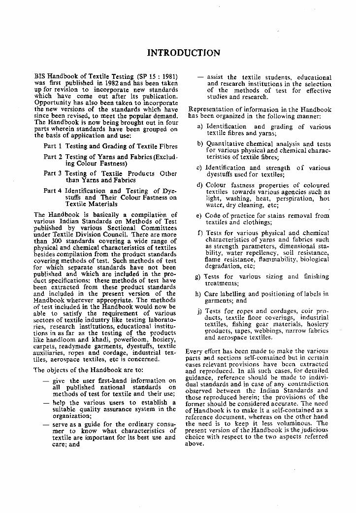
BIS Handbook of Textile Testing (SP 15 : 1981) was first published in 1982and has been taken up for revision to incorporate new standards which have come out after its publication. Opportunity has also been taken to incorporate the new versions of the standards which have since been revised, to meet the popular demand. The Handbook is now being brought out in four parts wherein standards have been grouped on the basis of application and use:
Part 1 Testing and Grading of Textile Fibres
Part 2 Testing of Yarns and Fabrics (Exclud- ing Colour Fastness)
Part 3 Testing of Textile Products Other than Yarns and Fabrics
Part 4 Identification and Testing of Dye- stuffs and Their Colour Fastness on Textiie Materials
The Handbook is basically a compilation of various Indian Standards on Methods of Test published by various Sectional Committees under Textile Division Council. There are more than 300 standards covering a wide range of physical and chemical characteristics of textiles besides compilation from the product standards covering methods of test. Such methods of test for which separate standards have not been published and which are included in the pro- duct specifications: these methods of test have been extracted from these product standards and included in the present version of the Handbook wherever appropriate. The methods of test included in the Handbook would now be able to satisfy the requirement of various sectors of textile industry like testing laborato- ries, research institutions, educational institu- tions in as far as the testing of the products like handloom and khadi, powerloom, hosiery, carpets, readymade garments, dyestuffs, textile auxiliaries, ropes and cordage, industrial tex- tiles, aerospace textiles, etc is concerned.
The objects of the Handbook are to: - give the user fist-hand information on
all published national standards on methods of test for textile and their use;
- help the various users to establish a suitable quality assurance system in the organization;
- serve as a guide for the ordinary consu- mer to know what characteristics of textile are important for its best use and care; and
- assist the textile students, educational and research institutions in the selection of the methods of test for effective studies and research.
Representation of information in the Handbook has been organized in the following manner:
a)
b)
4
d)
e)
f )
Identification and grading of various textile fibres and yarns;
Quantitative chemical analysis and tests for various physical and chemical charac- teristics of textile fibres;
Identification and strength of various dyestuffs used for textiles;
Colour fastness properties of coloured textiles towards various agencies such as light, washing, heat, perspiration, hot water, dry cleaning, etc;
Code of practice for stains removal from textiles and clothings;
Tests for various physical and chemical characteristics of yarns and fabrics such as strength parameters, dimensional sta- bility, water repellency, soil resistance, flame resistance, flammability, biological degradation, etc;
g) Tests for various sizing and finishing treatments;
h) Care labelling and positioning of labels in garments; and
j) Tests for ropes and cordages, coir pro- ducts, textile floor coverings, industrial textiles, fishing gear materials, hosiery products, tapes, webbings, narrow fabrics and aerospace textiles.
Every effort has been made to make the various parts and sections self-contained but in certain cases relevant provisions have been extracted and reproduced. In all such cases, for detailed guidance, reference should be made to indivi- dual standards and in case of any contradiction observed between the Indian Standards and those reproduced herein; the provisions of the former should be considered accurate. The need of Handbook is to make it a self-contained as a reference document, whereas on the other hand the need is to keep it less voluminous. The present version of the Handbook is the judicious choice with respect to the two aspects referred above.

As in the Original Standard, this Page is Intentionally Left Blank
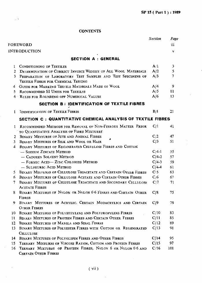
SP 15 ( Part 1) : 1989
CONTENTS
Section
FOREWORD
INTRODUCTION
SECTION A : GENERAL
1 2 3
4
5 6
1 IDENTIFICATION OF TBXTILB FIBRES B/l
1
2 3 4
5
6
7
8
9
10
11
12 13
14
15 16
CONDITIONING OF TEXTILES
DETERMINATION OF CORRECT INVOICE WEIGHT OF ALL WOOL MATERIALS
PREPARATION OF LABORATORY TEST SAMPLES AND TEST SPECIMENS OF
TBXTILE FIBRES FOR CHEMICAL TESTING
GUIDE FOR MARKING TEXTILE MATERIALS MADE OF WOOL
RECOMMENDED SI UNITS FOR TEXTILES
RULES FOR ROUNDING OFF NUMBRICAL VALUES
SECTION B : IDENTIFICATION OF TEXTILE FIBRES
A/l
Al2 Al3
Al4 Al5
Al6
SECTION C : QUANTITATIVE CHEMICAL ANALYSIS OF TEXTILE FIBRES
RECOMMENDED METHODS FOR REMOVAL OF NON-FIBROUS MATTER PRIOR
TO QUANTITATIVE ANALYSIS OF FIBRB MIXTURES
BINARY MIXTURES OF JUTE AND ANIMAL FIBRES
BINARY MIXTURES OF SILK AND WOOL OR HAIR *
BINARY MIXTURES OF REGENERATED CELLULOSE FIBRES AND COTTON - SODIUM ZINCATE METHOD - CADOXEN SOLVENT METHOD
- FORMIC ACID- ZINC CHLORIDE METHOD - SULPHURIC ACID METHOD
BINARY MIXTURES OF CELLULOSE TRIACETATE AND CERTAIN OTHER FIBRES
BINARY MIXTURES OF CELLULOSE ACETATE AND CERTAIN OTHER FIBRES
BINARY MIXTURES OF CELLULOSE TRIACETATE AND SECONDARY CELLULOSE
ACETATE FIBRES
BINARY MIXTURES OF NYLON OR NYLON 6.6 FIBRES AND CERTAIN OTHER
FIBRES
BINARY MIXTURES OF ACRYLIC, CERTAIN MODACRYLICS AND CBRTAIN
OTHER FIBRES
BINARY MIXTURES OF POLYETHYLENE AND POLYPROPYLENE FIB&S
BINARY MIXTURES OF PROTEIN FIBRES AND CERTAIN OTHER FIBRES
BINARY MIXTURES OF MANILA AND SISAL FIBRES
BINARY MIXTURES OF POLYESTER FIBRES WITH COTTON OR REGBNERATBD
CELLULOSE
BINARY MIXTURES OF POLYOLEFIN FIBRES AND OTHER FIBRES
TERNARY MIXTURES OF VISCOSE RAYON, COTTON AND PROTEIN FIBRBS
TERNARY MIXTURES OF PROTEIN FIBRBS, NYLON 6 OR NYLON 6.6 AND
CERTAIN OTHER FIBRES
Page . . . 111
V
3 5 7
9 11 13
21
C/l 41
c/2
Cl3
47
51
c/4-1 55
C/4-2 57
c/4-3 59 c/4-4 61 Cl5 63
C/6 67
Cl7 71
C/8 75
C/9 79
CjlO 83
c/11 85
c/12 89
c/13 91
c/14 95 c/15 97
C/16 101
( vii)
SP 15 ( Part 1 ) : 1989
Section
SECTION 0 : DETERMINATION OF PHYSICAL CHARACTERISTICS TEXTILE FIBRES
1 LINEAR DENSITY OF TEXTILE FIBRES ( GRAVIMETRIC METHOD )
2 TENSILE CHARACTERISTICS OF INDIVIDUAL TEXTILE FIBRES
Cotton
8
9 10
ESTIMATION OF MOISTURE IN COTTON ’
MICRONAIRE VALUE OF COTTON FIBRES
COTTON FIBRE MATURITY ( SODIUM HYDROXIDE SWELLING METHOD )
COTTON FIBRE IMMATURITY COUNT - POLARIZED LIGHT METHOD
LINT AND TRASH CONTENT OF COTTON BY MEANS OF MBCHANICAL-
PNEUMATIC MACHINES
LENGTH PARAMETERS OF COTTON FIBRES
- ESTIMATION OE’ LENGTH AND LENGTH DISTRIBUTION BY ARRAY
METHOD - ESTIMATION OF LENGTH AND LBNGTH DISTRIBUTION BY THICK.NESS
SCANNING METHOD
- ESTIMATION OF LENGTH AND LENGTH DISTRIBUTION BY OPTICAL
SCANNING METHOD
NEP COUNT IN COTTON
BUNDLE STRENGTH ( TENACITY ) OF COTTON FIBRES
Wool
11 WOOL FIBRE DIAMETER - PROJE~ION MICROSCOPE METHOD
12 WOOL FIBRE DIAMETER BY AIR FLOW METHOD
13 PERCENTAGE OF MBDULLATED FIBRES IN WOOL
14 MEAN FIBRE LENGTH OF WOOL
15 WOOL FIBRE LENGTH ( BARBB AND HAUTBUR ) USING A COMB SORTER
16 STAPLE LENGTH OF GREASY WOOL
17 CRIMP IN WOOL
18 MOISTURE IN WOOL
Man-Made Staple Fibres ( MMSF ) 19 DETERMINATION OF LENGTH
20 DETERMINATION OF LINEAR DBNSITY
21 TESTING VISCOSE RAYON STAPLE FIBRES
22 UNCUT INDIAN JUTE MESTA AND BIMLI ‘- GENERAL
- REED LENGTH - ROOT CONTENT
- DEFECTS
- FOREIGN MATTER ’
- BULK DENSITY
- BUNDLB STRENGTH
- FINENESS
D/l D/2
107
111
D/3 117
D/4 119
D/5 125
D/6 129
D/7 131
D/8 D/8-1
135
137
D/8-2 141
D/8-3 143
D/9 145 D/10 149
D/11 155 D/12 161 D/13 169 D/14 171 D/l5 173 D/16 177
D/17 179
D/18 181
D/19
D/20
D/21
D/22
D/22- 1
D/22-2 D/22-3
D/22-4
D/22-5
D/22-6
D/22-7 D/22-8
185
189
191
195 197
199 201
203 205 207
209
213
Page
OF
( viii )
SP 15 ( Part 1) : 1989
23 24
25
26
1
2
3
4
5
TESTS FOR INDIAN KAPOK
PERCENT BY MASS OF LONG, MEDIUM AND SHORT COIR FIBRES
PERCENTAGE OF IMPURITIES IN COIR FIBRES
MOISTURE CONTENT IN COIR FIBRES
SECTION E : CHEMICAL TESTS FOR TEXTILE FIBRES
ESTIMATION CARBOXYLIC ACID GROUPS IN CELLULOSIC TEXTILE
MATERIALS
- IODOMETRIC METHOD
- SODIUM CHLORIDE-SODIUM BICARBONATE METHOD
DETERMINATION OF ACETIC ACID CONTENT OF ACETATE OR TRIACETATE
FIBRE MATERIALS
DAMGE IN COTTON FIBRES DUE TO MICRO ORGANISM
DETERMINATION OF KEMP CONTENT OF RAW WOOL DETERMINATION OF CLEAN FIBRE AND VEGETABLE MATTER CONTENT AND
SCOURING YIELD OF RAW WOOL
DETERMINATION OF SOLUBILITY OF WOOL IN ALKALI
DETER&NATION OP SOLUBILITY OF WOOL IN UREA-BISULPHITE SOLUTION
DETERMINATION OF WOOL CONTENT IN WOOLLEN TEXTILE MATERIALS
DETERMINATION OF SULPHATE CONTENT IN TEXTILE MATERIALS
SECTION F : GRADING OF TEXTILE FIBRES
GRADING OF VISCOSE RAYON CUT STAPLE FIBRES ( REGULAR )
GRADING OF WOOL FOR EXPORT
GRADING OF WHITE, TOSSA AND DAISEE UNCUT INDIAN JUTE
GRADING OF UNCUT INDIAN Hi%1
GRADING OF UNCUT INDIAN MESTA GRADING OF FINENESS GRADES OF WOOL GRADING OF FINENESS GRADES OF WOOL TOPS
GRADES OF UNDYED MEDULLATED WOOL
GRADING OF INDIAN KAPOK
Section Page
D/23 219
D/24 221
D/25 223
D/26 225
E/l-l 229 E/1-2 231
E/2 233
E/3 235
E/4 241
E/5 243
E/6 247
E/7 251
E/8 255
E/9 257
F/l 263
F/2 265
F/3 269
F/4 273
F/5 275
F/6 277
F/7 279
F/8 283
F/9 285
SECTION G : INDEX TO INDIAN STANDARDS COVERED IN THIS HANDBOOK
1 LIST OF INDIAN STANDARDS REFERRED G/I 289

SP 15 ( Part 1) : 1989
SECTION A
GENERAL

As in the Original Standard, this Page is Intentionally Left Blank
CONDITIONING OF TEXTILES
( Source : IS
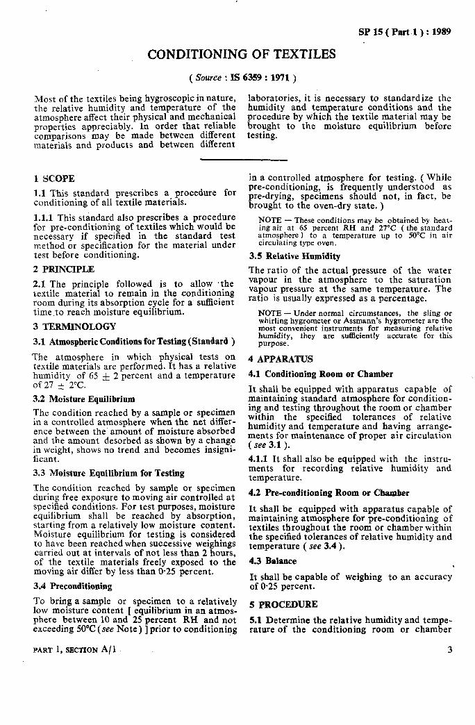
Most of the textiles being hygroscopic in nature, the relative humidity and temperature of the atmosphere affect their physical and mechanical properties appreciably. In order that reliable comparisons may be made between different materials and products and between different
6359 : 1971 )
laboratories, it is necessary to standardize the humidity and temperature conditions and the procedure by which the textile material may be brought to the moisture equilibrium before testing.
1 SCOPE
1.1 This standard prescribes a procedure for conditioning of all textile materials.
1.1.1 This standard also prescribes a procedure for pre-conditioning of textiles which would be necessary if specified in the standard test method or specification for the material under test before conditioning.
2 PRINCIPLE
2.1 The principle followed is to allow .the textile material to remain in the conditioning room during its absorption cycle for a suflicient time .to reach moisture equilibrium.
3 TERMINOLOGY
3.1 Atmospheric Conditions for Testing (Standard )
The atmosphere in which physical tests on textile materials are performed. It has a relative humidity of 65 rf 2 percent and a temperature of27 * 2°C.
3.2 Moisture Equilibrium
The condition reached by a sample or specimen in a controlled atmosphere when the net differ- ence between the amount of moisture absorbed and the amount desorbed as shown by a change in weight, shows no trend and becomes insigni- ficant.
3.3 Moisture Equilibrium for Testing
The condition reached by sample or specimen during free exposure to moving air controlled at specified conditions. For test purposes, moisture equilibrium shall be reached by absorption, starting from a relatively low moisture content. Moisture equilibrium for testing is considered to have been reached when successive weighings carried out at intervals of not less than 2 hours, of the textile materials freely exposed to the moving air differ by less than O-25 percent.
3.4 Preconditioning
To bring a sample or specimen to a relatively low moisture content [ equilibrium in an atmos- phere between 10 and 25 percent RH and not exceeding 50°C! (see Note) ] prior to conditioning
PART 1, SECTION A/ 1
in a controlled atmosphere for testing. ( While pre-conditioning, is frequently understood as pre-drying, specimens should not, in fact, be brought to the oven-dry state. )
NOTE - These conditions may be obtained by heat- ing air at 65 vercent RH and 27°C ( the standard atmosphere) to a temperature up to‘ 50°C in air circulating type oven.
3.5 Relative Humidity
The ratio of the actual pressure of the water vapour in the atmosphere to the saturation vapour pressure at the same temperature. The ratio is usually expressed as a percentage.
NOTE - Under normal circumstances, the sling or whirling hygrometer or Assmann’s hygrometer are the most convenient instruments for measuring relative humidity, they are sufficiently accurate for this purpose.
4 APPARATUS
4.1 Conditioning Room or Chamber
It shall be equipped with apparatus capable of maintaining standard atmosphere for condition- ing and testing throughout the room or chamber within the specified tolerances of relative humidity and temperature and having arrange- ments for maintenance of proper air circulation ( see 3.1 ).
4.1.1 It shall also be equipped with the instru- ments for recording relative humidity and temperature.
4.2 Pre-conditioning Room or Chamber
It shall be equipped with apparatus capable of maintaining atmosphere for pre-conditioning of textiles throughout the room or chamber within the specified tolerances of relative humidity and temperature ( see 3.4 ).
4.3 Balance .
It shall be capable of weighing to an accuracy of 0.25 percent.
5 PROCEDURE
5.1 Determine the relative humidity and tempe- rature of the conditioning room or chamber
3

SP 15 ( Part 1 ) : 1989
( see 4.1 ) and, if pre-conditioning is also to be carried out, find the relative humidity and tem-
5.3 Expose the specimen or sample ( already
perature of the pre-conditioning cabinet or pre-conditioned, if so required) in the standard atmosphere in such a way as to expose, as far as
room to check whether the conditions meet the possible, all portions of the material to the specified values of relative humidity and tem- atmosphere until the moisture equilibrium is perature or not. If the conditions are not as required, make adjustments to bring them to
attained ( see Notes 1 and 2).
the desired limits of temperature and humidity. NOTES
5.1.1 If both pre-conditioning and conditioning are prescribed in the test method or the speci-
1 In case the material received is in package
fication for the material, proceed as given form, it is preferable to prepare test specimens in loose or open form so that all portions get uniformly
in 5.2 and 5.3, and if only conditioning has been prescribed, omit 5.2.
5.2 Expose the specimen or sample in the atmosphere for pre-conditioning in such a way as to expose, as far as possible, all portions of the material to the atmosphere until the mois- ture equilibrium is attained under 5.3 ).
( see Note 1
exposed to the pre-conditioning or conditioning atmospheres. For example, in case of yarn in the form of cones or cheeses, suitable skeins may be prepared for conditioning.
2 For guidance purposes, it may be noted that the minimum time required for the various types of textile materials having moisture regain value of less than 5 percent is about 6 hours to reach moisture equilibrium while for those having moisture regain values of more than 5 percent it is 24 hours.
4 HANDBOOK OF TEXTILE .TBSTING.

DETERMINATION OF CORRECT INVOICE ALL WOOL MATERIALS
( Source : IS 4902 : 1981)
SP 15 ( Part 1) : 1989
WEIGHT OF
The test is used for eliminating unnecessary ( obtained by adding appropriate commercial and undesirable variations in testing procedure moisture regain to oven-dry weight of the for the determination of correct invoice weight material ) of all wool yarns and fabrics.
1 SCOPE
1.1 This standard prescribes a method for determination of correct invoice weight of all wool tops, yarns and fabrics.
2 APPARATUS
2.1 Drying Oven
preferably of the ventilated type, capable of maintaining an inside temperature of 105 f 3Y!.
solvent at a minimum rate of 6 extractions per hour. Remove the test specimen and dry it to constant weight in an oven at a temperature of 105 f 3°C. Determine the weight ofthe dried extracted specimen ( IV, ).
4.3 Repeat the test with one more test speci- men.
5 CALCULATION
5.1 Calculate the correct invoice weight of the
2.2 Weighing Balance consignment by the following formula:-
capable of weighing accurately to O*OOO 1 g. w,=wx 2.3 Soxblet Apparatus
with auxiliaries like beaker, weighing flasks, etc. where
3 REAGENTS W, = correct invoice weight consignment,
of the
3.0 Quality of Reagents Unless specified otherwise, pure chemicals shall be employed in tests and distilled water shall be used where the use of water as reagent is intended.
W = original weight of the consign- ment,
lV,-, = oven dry weight of the deoiled specimen,
NOTE - ‘Pure chemicals’ shall mean chemicals that do not contain impurities which affect the test results.
3.1 Benzene
sp gr O-879 0. 3.2 Methanol sp gr 0.791 7. 4 PROCEDURE
W, = original weight of the specimen, i and
R = commercial moisture regain value.
4.1 Determine the weight of the consignment ( W ). From the test sample of 200 g, take a test specimen weighing about 10 g, and put it in a polyethylene bag of known weight, and seal it in the environment in which the consignment is housed. Weigh the bag and tid the weight of the test specimen ( Wg ). Take care to see that no change in the moisture content of the test specimen takes place during the drawing and weighing of the sample.
5.1.1 Calculate the correct invoice weight of the consignment with the other specimen by using the formula given in 5.1.
5.2 Calculate the average of the two values obtained as in 5.1 and 5.1.1, if the difference between the two is not more than 0.5 percent.
6 REPORT
4.2 Take test specimen and wrap it in a filter paper. Extract the specimen with the 300 ml of benzene-ethanol mixture 1 3 : 2 (v/v ) ] in a Soxhlet apparatus for 3 hours, siphoning the
6.1 The report information:
shall include the following
a) Type of material,
b) Invoice weight of the consignment,
c) Commercial moisture regain values used, and
d) Correct invoice weight of the consign- ment.
PART 1, SECTION A/2 5
’

As in the Original Standard, this Page is Intentionally Left Blank
SP 15 ( Part 1) : 1989
PREPARATION OF LABORATORY TEST SAMPLES AND TEST SPECIMENS OF TEXTILE FOR FIBRES FOR
CHEMICAL TESTING
( Source : IS 9022 : 1979 )
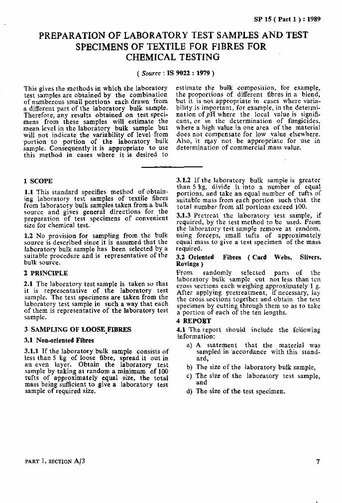
This gives the methods in which the laboratory test samples are obtained by the combination of numberous small portions each drawn from a different part of the laboratory bulk sample. Therefore, any results obtained on test specr- mens from these samples will estimate the mean level in the laboratory bulk sample but will not indicate the variability of level from portion to portion of the laboratory bulk sample. Consequently it is appropriate to use this method in cases where it is desired to
estimate the bulk composition, for example, the proportions of different fibres in a blend, but it is not appropriate in cases where varia- bility is important, for example, in the determi- nation of pH where the local value is signih- cant, or in the determination of fungicides, where a high value in one area of the material does not compensate for low value elsewhere. Also, it may not be appropriate for use in determination of commercial mass value.
1 SCOPE
1.1 This standard specifies method of obtain- ing laboratory test samples of textile fibres from laboratory bulk samples taken from a bulk source, and gives general directions for the preparation of test specimens of convenient size for chemical test.
1.2 No provision for sampling from the bulk source is described since it is assumed that the laboratory bulk sample has been selected by a suitable procedure and is representative of the bulk source.
2 PRINCIPLE
2.1 The laboratory test sample is taken so that it is representative of the laboratory test sample. The test specimens are taken from the laboratory test sample in such a way that each of them is representative of the laboratory test sample.
3 SAMPLING OF LOOSE_FIBRES
3.1 Non-oriented Fibres
3.1.1 If the laboratory bulk sample consists of less than 5 kg of loose fibre, spread it out in an even layer. Obtain the laboratory test sample by taking at random a minimum of 100 tufts of approximately equal size, the total mass being sufficient to give a laboratory test samnle of reauired size.
3.1.2 If the laboratory bulk sample is greater than 5 kg, divide it into a number of equal portions, and take an equal number of tufts of suitable mass from each portion such that the total number from all portions exceed 100. 3.1.3 Pretreat the laboratory test sample, if required, by the test method to be used. From the laboratory test sample remove at random, using forceps, small tufts of approximately equal mass to give a test specimen of the mass required. 3.2 Oriented Fibres ( Card Webs, Slivers, Rovings ) From randomly selected parts of the laboratory bulk sample cut not less than ten cross sections each weighing approximately 1 g. After applying pretreatment, if necessary, lay the cross sections together and obtain the test specimen by cutting through them so as to take a portion of each of the ten lengths. 4 REPORT 4.1 The report should include the following information:
a) A statement that the material was sampled in ‘accordance with this stand- ard,
b) The size of the laboratory bulk sample, c) The size of the laboratory test sample,
and d) The size of the test specimen.
PART 1, SECTION A/3

As in the Original Standard, this Page is Intentionally Left Blank

GUIDE FOR MARKiNG TEXTILE MATERIALS MADE 0F WOOL
( Source : IS 1793 : 1973 )
1 SCOPE
1.1 This standard is intended to provide gai- dance for application of ~terms ti be Bsed in marking textile materials containing not less than 20 percent of wool fibre.
1.2 It also lays down the methods for determin- ing the contents of wool and other fibres of the material.
2 MARKING
2.1 Textile materials should be marked as given on the basis of content of wool fibres: below
a) All Wool - A textile material should be marked ‘All Wool’ if the material com- prises of wool fibres only subject to the tolerances given below:
1) Manufacturign tolerance - up to
b)
J
3 percent of inadvertent impurities, and
2) An allowance - up to 5 percent of material other than wool fibres used to provide a decorative or ornamen- tation effect.
Blended Wool - The textile material should be marked ‘BLENDED WOOL’ if it contains not less than 20 percent wool fibres. However, a manufacturing tolerance up to 3 percent on wool con- tents shall be permitted. NOTES 1 All reference to the percentage contents mean percentages by mass calculated from the mass of materials when in standard condition, namely, their oven-dry mass plus the appropri- ate regain. 2 In all cases the more detailed descrintion of the contents of the material shall be given by indicating the percentage of the wool and other fibres in descending order used in the manu- facture of the textile material. However, such a description should not be misleading.
3 METHODS OF TEST
3.1 For Textile Materials Marked ‘All Wool’
3.1.1 Take about 10 to 15 g of the material and extract it in a Soxhlet apparatus with light petroleum hydrocarbon solvent for 1 hour at a minimum rate of 6 cycles per hour. Allow the light petroleum hydrocarbon solvent to evapo- rate and then extract in a Soxhlet apparatus with water for 2 hours at a minimum rate of 6 cycles per hour.
3J.2 Take a representative sample weighing about 5 g from the pretreated sample and place
:it in a suitable container. Place the specimen in the drying oven maintained at a temperature of 105 f 3°C and dry the sample to a constant mass. The mass shall be taken as constant when the difference between the two successive weighings made at intervals of 20 minutes is less than 0.05 percent.
3.1.3 Determine the mass of the sample without removing it from the oven. In case the drying oven is not provided with the weighing balance, remove the sample from the oven and transfer it to a weighing container of known mass pro- vided with a light lid. The transference of the sample should be done in as little a time as possible. Cool the sample and the container in a dessicator to room temperature before weigh- ing. Weigh the container and then tind the mass ( J4r ) of the sample to an accuracy of 10 mg.
3.1.4 Examine the sample visually. If this reveals the presence of decorative yarns or fibres of non-wool composition in the sample, carefully dissect these fibres of non-wool com- position in the sample. Carefully dissect these fibres or yarns out and dry them to constant mass at 105 f 3°C. Determine the mass to an accuracy of 10 mg (M, ).
3.1.5 Transfer the remaining sample in a beaker together with atleast 10 times its mass of 5 percent solution of sodium or potassium hydroxide and boil slowly until the wool fibres become gelatinous and dissolve. After a period of 10 minutes of boiling, filter through a Gooch crucible and wash the residue first with warm water, then with 3 percent solution of glacial acetic acid and finally with hot water. Dry the residue at 105 f 3°C.
3.1.6 Examine carefully the residue and the pores of the crucible for non-fibrous matter, for example, burrs, seeds, finishing materials, dyestuff residues, as well as for incompletely dissolved wool. If any such contaminant is present, it shall be dissolved or otherwise removed. For example, undissolved wool pro-’ tein shall be removed by treatment with fresh boiling 5 percent sodium hydroxide or potas- sium hydroxide; and burrs and seeds shall be lifted out with forceps. Rinse and dry the residue to constant mass at 105 f 3°C. Deter- mine the mass of the residue to an accuracy of 1Omg (MS).
3.1.7 Determine the percentages of non-wool decorative fibres or yarns and non-wool fibres
9

SP 15 ( Part 1) : 1989
present as madvertent impurities by the. follow- ing formulae:
y = cirzytage moisture regain for .
a) Percentage of non-wool decorative fibres .b) Percentage of non-wool fibres percent as iI42 ( 100 + x ) x 100
= M~(loo+x)+(M~--Mg)(100+y : inadvertent impurities = M, x 100
Ml
where 3.18 Similarly, determine the percentages in x = percentage moisture regain for the remaining samples and calculate the
non-wool decorative fibres, and average.
10 HANDBOOK OF TEXTILE TESTING

. SP 15 (.PM 1 ) : 1989
RECOMMENDED SI UNITS FOR TEXTILES
( source : SP 11 : 1973 )
In textile trade and industry the measurement of various characteristics plays an important role in the analysis, quality control, sale- purchase and checking up for compliance to the standard. For easy understanding and inter- pretation of figures by different interests, it becomes essential to changeover to a unified set of units which have been accepted at
national as well as international level. There- fore, this has been issued for the guidance of users for changing overto SI system, with a view to unifying the set-up of units in various facets of textile trade and industry. Wherever the SI units differ from metric units, the metric units with which the industry is familiary have also been given.
,
mass of 1 kilogram, gives it an acceleration of
recommended for use in the textile industry
1 SCOPE
and trade.
I metre per second.
2 TERMINOLOGY
1.1 This Dublication contains a list of SI units
2.1 Newton (N)
Force which, when applied_ to a body haying a
1 millinewton ( mN ) = lo-3N ( newton )
1 gramforce ( gf)
1 kilogram force ( kgf) = 9.806 65 N
3 LIST OF UNITS
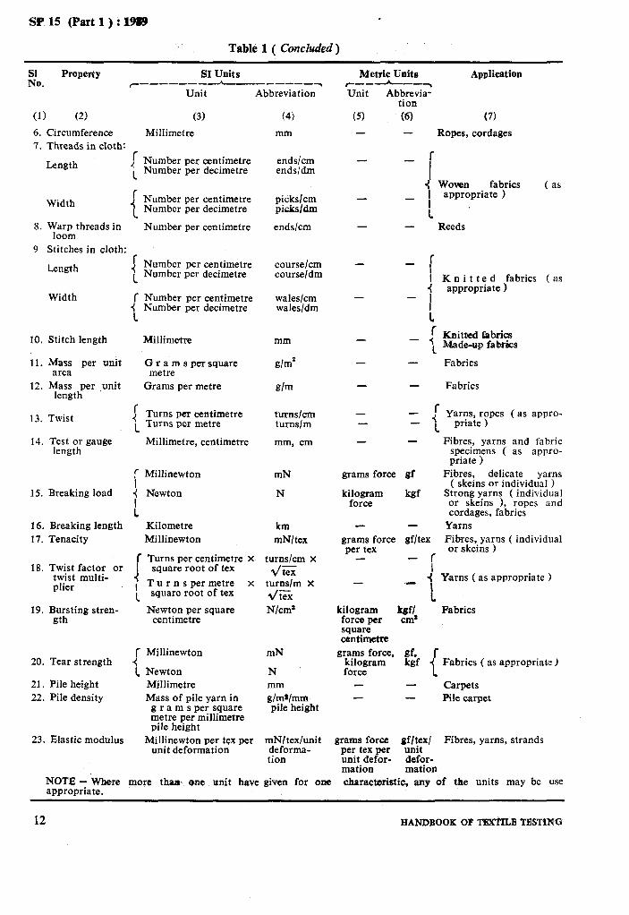
3.1 Table 1 lists the
( newton )
= 9.806 65 mN ( millinewton )
( their metric equivalents, wherever necessary), abbreviations and their fields of application.
characteristics, SI units
Table 1 Recommended SI Units for Textiles
&. Property SI Units Metric Units Application
~----~--~-_----___~ r---h---~ Unit
(1) (2)
1. Length
(3) f Millimetre I Millimetre, ccntimetre
< 1 Metre 1
f Millimetre I Centimetre
2. Width ’ Millimetre, centimetre <
1 Centimetre; metre
r Micrometre ( micron ) 3 Thickness { Millimetre
I
r Tex I Millitex
4. *Linear density I -j Decitex
1 Kilotex 1
5. Diameter r Micrometre ( micron 1 i 1 Millimetre
Abbreviation -Unit Abbrevia- tion
(4) (5) (6) mm - - mm, cm - -
m - -
m - - cm - mm, cm -
- cm, m - -
pm - - mm - -
tex mtex dtex
ktex
- - - - -
w-n - -
mm -
(7) Fibres Samples and test speci- mens ( as appropriate )
Yarw&,crpes and cordages,
Narrow fabrics Other fabrics Samples and test specimen
( as appropriate) Carpets, druggets, durries
( as appropriate )
Delicate fabrics Other fabrics, carpets,
felts
Yarns Fibres Filament and filament
yarns Slivers, ropes and corda-
ges
Fibres
Yarns, ropes, cordages
*For conversion of talues in’ traditional counts to the tex and vice verBa, reference to IS : 3639-1966 ‘Conversion factors and conversion tables for yarn counts’ shall be made.
. --,
PART I,, SB~ION 45 : ; 11
SP 15 (Part 1) : 1989 .
Table 1 ( Concluded)
Eo. Property SI Units
7-------- h-_-----__-~ Unit Abbreviation
(1) (2) 6. 7.
Circumference Threads in cloth: ,- Length :
1
8.
9
Width : 1
Warp threads in loom
Stitches in cloth:
Length
Width
10.
11.
12.
Stitch length Millimetre
Mass per unit area
Mass per ,unit length
13.
14.
Twist I 1
Test or gauge length
15.
16. 17.
i Breaking load (
: Breaking length Tenacity
18. f Turns per centimetre x
Twist factor or twist multi- I
19.
plier I 1
Bursting stren- gth
20.
21. 22.
r Tear strength 4
1 Pile height Pile density
23. Elastic modulus
(3) (4)
Millimetre mm
Number per centimetre ends/cm Number per decimetre ends/dm
Number per centimetre picks/cm Number per decimetre picksldm
Number per centimetre ends/cm
Number per centimetre course/cm Number per decimetre course/dm
Number per centimetre wales/cm Number per decimetre wales/dm
Gramspersquare metre
Grams per metre
mm
g/m*
g/m
Turns per centimetre turns/cm Turns per metre turns/m
Millimetre, centimetre mm, cm
Millinewton mN
Newton N
Kilometre Millinewton
km mN/tex
turns/cm X
d/tex turns/m X */tex N/cm’
square root of tex
T u r n s per metre x square root of tex
Newton per square centimetre
Millinewton mN
Newton Millimetre Mass of pile yarn in
g r a m s per square metre per millimetre pile height
Millinewton per tex per unit deformation
N mm dm~lmm pile height
mNltex/unit deforma- tion
Metric Units Application c---L-~ Unit Abbrevia-
tion (5) tQ (7)
- Ropes, cordages
fabrics _ 1 ypztpriate 1
( as -
1 - Reeds
- : I Knitted fabrics (as
4 appropriate 1 -
- I 1 f Knitted fabrics -
- I Made-up fab&s
- - Fabrics
- Fabrics
- -
1 _// Yarns, ropes (as appro-
1 priate )
grams force gf
kilogram force
kgf
grams force gf/tex per tex
- r i
- -:
1 kilogram kef/ force per cm* square centimelle
Fibres, yarns and fabric specimens ( as appro- priate 1
Fibres, delicate yarns ( skeins or individual )
Strong yarns ( individual or skeins ), ropes and cordages, fabrics
Yarns F&es, yarns ( individual or skeins >
Yarns ( as appropriate )
Fabrics
grams force, gf, r kilogram kgf
I Fabrics ( as appropriate )
force Carpets Pile carpet
grams force. gf/tex/ Fibres, yarns, strands per tex per unit unit defor- defor- mation mation
NOTE - Where more thm. one unit have given for one appropriate.
characteristic, any of the units may be use
12 HANDBOOK OF T3XTDX TBSTXNG

SP 15 ( Part 1 ) : 1989
RULES FOR ROUNDING OFF NUMERICAL VALUES
( Source : IS 2 : 1960 )
To round off a value is to retain a certain num- reporting or for drafting specifications, it is ber of figures, counted from the left, and drop the others so as to give a more rational form to the
necessary to prescribe rules for ‘rounding off numerical values as also for deciding on ‘the
value. As the result of a test or of a calculation number of figures’ to be retained. is generally rounded off for the purpose of
1 SCOPE
1.1 It prescribes rules for rounding off numeri- cal values for the purpose of reporting results of a test, an analysis; a measurement or a calcula- tion, and thus assisting in drafting specifications. It also makes recommendations as to the num- ber of figures that should be retained in course of computation.
2 TERMINOLOGY
2.0 For the purpose of this standard, the following definitions shall apply.
2.1 Number of Decimal I?~~wJ
A value is said to have as many decimal places as there are number of figures in the value, counting from the first figure after the decimal point and ending with the last figure on the right.
Example
Values Decimal Places
0.029 50 5
21.029 5 4
2 ooo*ooo 001 6 291.00 2
10.32 x 10s 2 ( see Note 1 )
NOTE 1 - For the purpose of this standard, the ex- pression lo-32 x 10’ should be taken to consist of two parts, the value proper which is 10’32 and the unit of expression for the value, 10’.
2.2 Number of Significant Figures
’ A value is said to have as many significant figures as there are number of significant digits ( see Note 2 ) in the value, counting from the left-most non-zero digit and ending with the right-most digit in the value.
Example
Values Significant Figures
o-029 500 5
o-029 5 3
10.029 5 6
PART 1, SECTION 46
Values SigniJicant Figures
2 ooo*ooo 001 10 5 677.0 5
567 700 6 56.77 x 10² 4
0 056.770 5 3 900 4
( see Note 3) b
NOTES
2 Any of the digits, 1, 2, 3, . . . . . . 9 occurring in a value shall be significant digit(s); and zero shall be a significant digit only when it is preceded by some other digit ( excepting zeros ) on its left. When appearing in the power of 10 to indicate the magni- tude of the unit in the expression of a value, zero shall not be a significant digit.
3 With a view to removing any ambiguity regarding the significance of the zeros at the end in a value like 3 900, it would be always desirable to write the value in the power-of-ten notation. For example, 3 900 may be written as 3’9 X 10³, 3’90 X lo3 or 3’900 x IO8 depending upon the last figure(s) in the value to which it is desired to impart significance.
2.3 Fineness of Rounding
The unit to which a value is rounded off.
For examble, a value may be rounded to the nearest O*OOO 01, 0400 2, O*OOO 5, 0*001,0.002 5, O-005, O-01, O-07, 1, 2.5, 10, 20, 50, 105 or any other unit depending on the fineness desired.
3 RULES FOR ROUNDING
3.0 The rule usually followed in rounding off a value to unit fineness of rounding is to keep un- changed the last figure retained when the figure next beyond is less than 5 and to increase by 1 the last figure retained when the figure next beyond is more than 5. There is diversity of practice when the figure next beyond the last figure retained is 5. In such cases, some compu- ters ‘round up’, that is, increase by 1, the last figure retained; others ‘round down’, that is, discard everything beyond the last figure retained. Obviously, if the retained value is always ‘rounded up’ or always ‘rounded down’, the sum and the average of a series of values so rounded will be larger or smaller than the cor- responding sum or average of the unrounded
-13
SP 15-f Part 1 ) : 1989
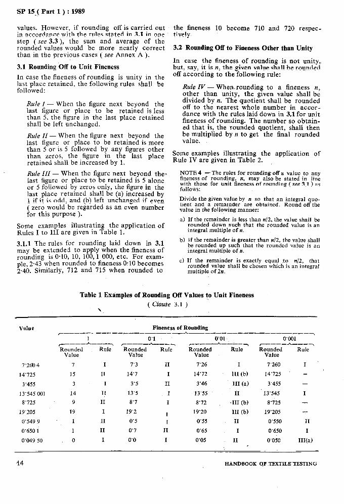
values. However, if rounding off is carried out in accordance with the rules stated in 3.1 in one step ( see 3.3 ), the sum and average of the rounded values would be more nearly correct than in the previous cases ( see Annex A ).
3.1 Rounding Off to Unit Fineness
In case the fineness of rounding is unity in the last place retained, the following rules shall be followed:
Rule I - When the figure next ‘beyond the last figure or place to be retained is less than 5, the figure in the last place retained shall be left unchanged.
Rule II-When the figure next beyond the last figure or place to be retained is more than 5 or is 5 followed by any figures other than zeros, the figure in the last place retained shall be increased by 1.
Rule III - When the figure next beyond the* last figure or place to be retained is 5 alone or 5 followed by zeros only, the figure in the last place retained shall be (a) increased by 1 if it is odd, and (b) left unchanged if even ( zero would be regarded as an even number for this purpose ).
Some examples illustrating the application of Rules I to III are given in Table 1.
3.1.1 The rules for rounding laid down in 3.1 may be extended to apply when the fineness of rounding is O-10, 10, 100,l 000, etc. For exam- ple, 2.43 when rounded to fineness O-10 becomes 2.40. Similarly, 712 and 715 when rounded to
the fineness 10 become 710 and 720 respec- tively.
3.2 Rounding Off to Fineness Other than Unity
In case the fineness of rounding is not unity, but, say, it is n, the given value shall be rounded off according to the following rule:
Rule IV - When rounding to a fineness n, other than unity, the given value shall be divided by n. The quotient shall be rounded off to the nearest whole number in accor- dance with the rules laid down in 3.1 for unit fineness of rounding. The number so obtain- ed that is, the rounded quotient, shall then be multiplied by n to get the final rounded value.
Some examples illustrating the application of Rule IV are given in Table 2.
NOTE 4 - The rules for rounding off a value to any fineness of rounding, II, may also be stated in line with those for unit fineness of rounding ( see 3.1) as follows:
Divide the given value by n so that an integral quo- tient and a remainder are obtained. Round off the value in the following manner:
a) If the remainder is less than n/2, the value shall be rounded down such that the rounded value is an integral multiple of n.
b) If the remainder is greater than n/2, the value shall be rounded up such that the rounded value is an integral multiple of n.
c) If the remainder is exactly equal to n/2, that rounded value shall be chosen which is an integral multiple of 2n.
Table 1 Examples of Rounding Off Values to Unit Fineness
( Clause 3.1 ) \
Value Fineness of Rounding c------ ~--__C__-__----_h---_____-___--_--__-~
1 0’1 r___-h ---7 r___-h---~ Rounded Rule Rounded Rule
Value Value
7’260 4 7 I 7’3 II
14’725 15 II 14’7 I
3’455 3 I 3’5 II
13’545 001 14 II 13’5 I
8’725 9 II 8’7 I
19’205 19 I 19’2 I 3’549 9 1 II 0’5 I
0’650 1 1 II 0’7 II
0’049 50 0 I 0’0 I
0’01’ ~__------~ Rounded Rule
Value
7’26 I
14’72 III (b)
3’46 III (a)
13’55 II
8’72 *III (b)
19’20 III (b)
0’55 II
0’65 I
0’05 II
0’001 ~----h---~ Rounded Rule
Value
7’260 I
’ 14’725 -
3’4.55 -
13’545 I
8’i25 -
19’205 -
0’550 II
0’650 I
0’050 III(a)
14 HANDBOOK QF .TJZXTILB TESTING

SP 15 ( Part 1 ) : 1989
Table 2 Examples of Rounding Off Values to Fineness Other than Unit
( Clause 3.2 )
,Value Fineness of Quotient Rounding,
n
(1) (2) (3)= (l)/(2)
1’647 8 0’2 8’239
2’70 0’2 13’5 2’496 8 0’3 8’322 7 1’75 0’5 3’5 0’687 21 0’07 9’817 3 0’875 0’07 12’5
325 50 6’5
1025 50 20’5
Rounded Final Quotient Rounded
Value
(4) (2$ ;>
8 1’6
14 2’8 8 2’4 4 2’0 10 0’70 12 0’84 6 3x10”
20 10x 10”
3.2.1 Fineness of rounding other than 2 and 5 is seldom called for in practice. For these cases, the rules for rounding may be stated in simpler form as follows:
4
\
b)
Rounding off to fineness 50, 5, 0.5, 0.05, O-005, etc.
Rule V - When rounding to 5 units, the given value shall be doubledand rounded off to twice the required fineness of rounding in accordance with 3.1.1. The value thus obtained shall be halved to get the final rounded value.
For example, in rounding off 975 to the nearest 50, 975 is doubled giving 1 950 which becomes 2 000 when rounded off to the nearest 100; when. 2 000 is divided by 2, the resulting number 1 000 is the rounded value of 975. Rounding off to fineness 20, 2, 0.2, 0.02, 0.002, etc.
Rule VI - When rounding to 2 units, the given value shall be halved and rounded off to half the required lkeness of round: ing in accordance with 3.1. The value thus obtained shall theri be doubled to get the kal rounded value.
For example, in rounding off 2.70 to the nearest O-2, 2.70 is halved giving 1.35 which becomes 1.4 when rounded off to the nearest 0.1; when 1.4 is doubled, the resulting number 2.8 is the rounded value.
3.3 Successive Rounding
The final rounded value shall be obtained from the most precise value available in one step only and not from a series of successive roundings. For example? the value O-549 9, when rounded to one significant figure, shall be
PART 1, SECTION A/6
written as 0.5 and not as 0.6 which is obtained as a result of successive roundings to 0.550, 0.55, and 0.6. It is obvious that the most precise value available is nearer to 0.5 and note to 0.6 and that the error involved is less in the former case. Similarly, O-650 1 shall be rounded off to 0.7 in one step and not successively to 0.650, 0.65 and O-6, since the most precise value available here is nearer to 0.7 than to O-6 ( see also Table 1 ).
NOTE 5 - In those cases where a final rounded vaiue terminates with 5 and it is intended to use it in fur- ther computation, it may be helpful to use a ‘+’ or ‘-’ sign after the final 5 to indicate whether a subsequent rounding should be up or down. Thus 3’214 7 may be written as 3’215- when rounded to a fineness of rounding 0’001. If further rounding to three signifi- cant figures is desired, this number would be rounded down and written as 3’21 which is in error by less than half a unit in the last place; otherwise, rounding of 3’215 would have yielded 3’22 which is in error by more than half a unit in the last place. Similarly, 3’205 4 could be written as 3’205+ when rounded to 4 significant figures. Further rounding to 3 significant figures would yield the value as 3’21.
In case the final 5 is obtained exactly, ii would be indicated by leaving the 5 as such without using ‘+’ or ‘-’ sign. In subsequent rounding the 5 would then be treated in accordance with Rule III.
4. NUMBER OF FIGURES TO BE RETAINED
4.0 Pertinent to the application of the rules for rounding off is the underlying decision as to the number of figures that should be retained in a given problem. The original values requiring to be rounded off may arise as a result ofa test, an analysis or a measurement, in other words, experimental results, or they may arise from computations involving several steps.
4.1 Experimental Results
The number of figures to be retained in an experimental result, either for the purpose of reporting or for guiding the formulation of specifications will depend on the significance of the figures in the value. This aspect has been discussed in detail under 4 of IS 787 : 1956 ‘Guide for inter-conversion of values from one system of units to another’ to which reference may be made for obtaining helpful guidance.
4.2 Computations
In computations involving values of different accuracies, the problem as to how many figures should be retained at various steps assumes a special significance as it would affect the accu- racy of the final result. The rounding off error will, in fact, be injected into computation every time an arithmetical operation is performed. It is, therefore, necessary to carry out the com- putation in such a manner as would obtain accurate results consistent with the accuracy of the data in hand.
15
SP 15 ( Part 1) : 1989
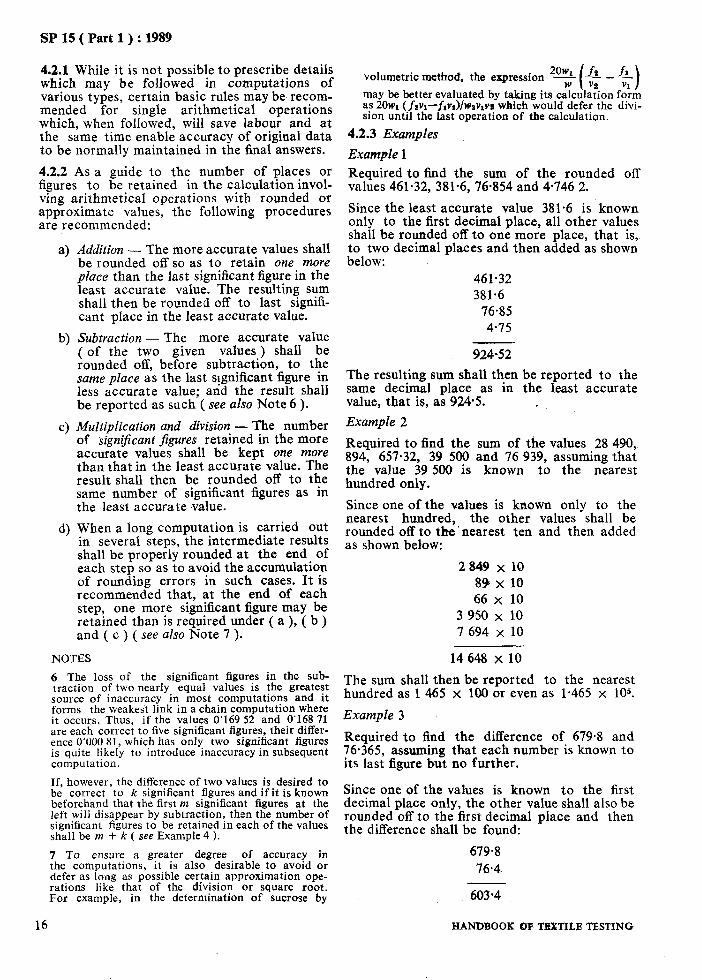
4.2.1 While it is not possible to prescribe details which may be followed in computations of various types, certain basic rules may be recom- mended for single arithmetical operations which, when followed, will save labour and at the same time enable accuracy of original data to be normally maintained in the final answers.
4.2.2 As a guide to the number of places or figures to be retained in the calculation invol- ving arithmetical operations with rounded or approximate values, the following procedures are recommended:
b>
C)
d)
Addition - The more accurate values shall be rounded off so as to retain one more place than the last significant figure in the least accurate value. The resulting sum shall then be rounded off to last signifi- cant place in the least accurate value.
Subtraction - The more accurate value ( of the two given values ) shall be rounded off, before subtraction, to the same place as the last significant figure in less accurate value; and the result shall be reported as such ( see also Note 6 ).
Multiplication and division - The number of Signijicant figures retained in the more accurate values shall be kept one more than that in the least accurate value. The result shall then be rounded off to the same number of significant figures as in the least accurate value.
When a long computation is carried out in several steps, the intermediate results shall be properly rounded at the end of each step so as to avoid the accumulation of rounding errors in such cases. It is recommended that, at the end of each step, one more significant figure may be retained than is required under ( a ), ( b ) and ( c ) ( see also Note 7 ).
NOTES
6 The loss of the significant figures in the sub- traction of two nearly equal values is the greatest source of inaccuracy in most computations and it forms the weakest link in a chain computation where it occurs. Thus, if the values 0’169 52 and 0’168 71 are each correct to five significant figures, their differ- ence 0’000 81, which has only two significant figures is quite likely to introduce inaccuracy in subsequent computation.
If, however, the difference of two values is desired to be correct to k significant figures and if it is known beforehand that the first m significant figures at the left will disappear by subtraction, then the number of significant figures to be retained in each of the values shall be m + k ( see Example 4 ).
Since one of the vaIues is known to the first decimal place only, the other value shall also be rounded off to the first decimal place and then the difference shall be found:
7 To ensure a greater degree of accuracy in the computations, it is also desirable to avoid or defer as long as possible certain approximation ope- rations like that of the division or square root. For example, in the determination of sucrose by
679.8 76.4
603.4
16 HANDBOOK QF TEXTILE TESTING
volumetric method, the expression *%!3(* _&)
may be better evaluated by taking its calculation form as 2Owl( fpv~-fiv&w~vlv~ which would defer the divi- sion until the last operation of the calculation.
4.2.3 Examples
Example 1
Required to find the sum of the rounded off values 461.32, 381.6, 76.854 and 4.746 2.
Since the least accurate ‘value 381.6 is known only to the first decimal place, all other values shall be rounded off to one more place, that is, to two decimal places and then added as shown below:
461.32 381.6
76.85 4-75
924-52
The resulting sum shall then be reported to the same decimal place as in the least accurate value, that is, as 9245. .
Example 2
Required to find the sum of the values 28 490, 894, 657.32, 39 500 and 76 939, assuming that the value 39 500 is known to the nearest hundred only.
Since one of the values is known only to the nearest hundred, the other values shall be rounded off to the’nearest ten and then added as shown below:
2849 x 10 89 x 10 66 x 10
3 950 x 10 7 694 x 10
14 648 x 10
The sum shall then be reported hundred as 1 465 x 100 or even
Example 3
to the nearest as l-465 x 105.
Required to find the difference of 679.8 and 76.365, assuming that each number is known to its last figure but no further.

SP 15 ( Part 1) : 1989
The difference, 603.4, shall be repor ted as such, Since the numerator here is correct to three
Examp le 4 significant figures, the denominator shall be
Required to evaluate 2/23 - J%@ correct taken as dT== l-414. Then,
to five significant figures. 2/2m Sin.ce = 1587 450 79
2/2X= l-577 973 38
35.2 - 1.414 - 24.89
and the result shall be reported
Example 6 and three significant figures at the left will dis- appear on subtraction, the number of significant figures retained in each value shall be 8 as shown below:
1.587 450 8 1.577 973 4
0.009 477 4
The result, 0.009 477 4, shall be reported as such ( or as 9.477 4 x 10-s) .
Example 5
Required to evaluate 35*2/2/zgiven that the numerator is correct to its last figure.
as 24.9.
Required to evaluate 3*78x/5*6, assuming that the denominator is true to only two significant figures.
Since the denominator here is correct to two significant figures, each number in the numera- tor would be taken up to three significant figures. Thus,
3.78 x 3.14 = 2.08 5.7
.
The result shall, however, be reported as 2.1.
ANNEX A
( czause 3.0 )
VALIDITY OF RULES
A-l. The validity of the rules for rounding off numerical values, as given in 3.1, may be seen from the fact that to every number that is to be ‘rounded down’ in accordance with Rule I, there corresponds a number that is to be ‘rounded up’ in accordance with Rule II. Thus, these two rules establish a balance between rounding ‘down’ and ‘up’ for all numbers other than those that fall exactly midway between two alternatives. In the latter case, since the figure to be dropped is exactly 5, Rule III, which specifies that the value should be rounded to its nearest even number, implies that round- ing shall be ‘up’ when the preceding figures are 1, 3, 5, 7, 9 and ‘down’ when they are 0, 2, 4, 6, 8. Rule III hence advocates a similar balance between rounding ‘up’ and ‘down’ (see also Note 8 ). This implies that if the above rules are followed in a large group of values in which
random distribution of figures occurs, the num- ber ‘rounded up’ and the number ‘rounded down’ will be nearly equal. Therefore, the sum and the average of the rounded values will be more nearly correct than would be the case if all were rounded in the same direction, that is, either all ‘up’ or all ‘down’.
NOTE 8 -From purely logical considerations a given value could have as well be rounded to an odd num- ber ( and not an even number as in Rule III > when the discarded figures fall exactly midway between two alternatives. But there is a practical aspect to the matter. The rounding off value to an even number facilitates the division of the rounded value by 2 and the result of such division gives the correct rounding off half the original unrounded value. Besides, the ( rounded) even values may generally be exactly divisible by many more numbers, even as well as odd than are the ( rounded 1 odd values.
PART 1, SECTION A/6 17

As in the Original Standard, this Page is Intentionally Left Blank

SP 15 ( Part 1) : 1989
SECTION B
IDENTIFICATION OF TEXTILE FIBRES

As in the Original Standard, this Page is Intentionally Left Blank
SP 15 ( Part 1) : 1989
IDENTIFICATION OF TEXTILE FIBRES
( Source : IS 667 : 1981)
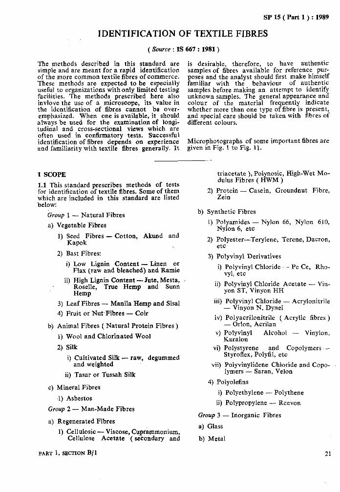
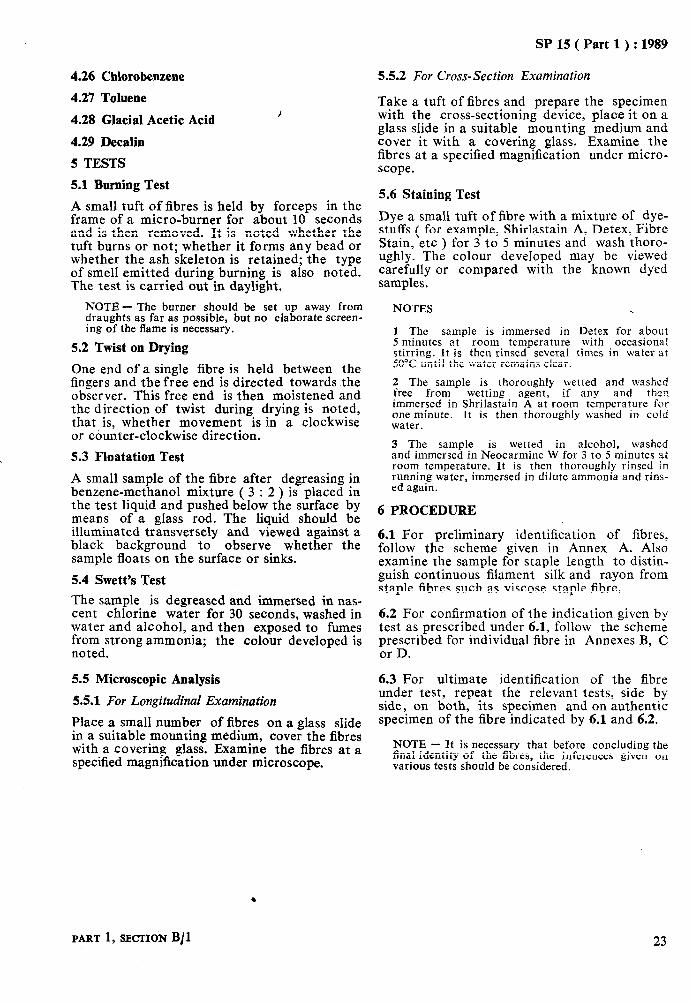
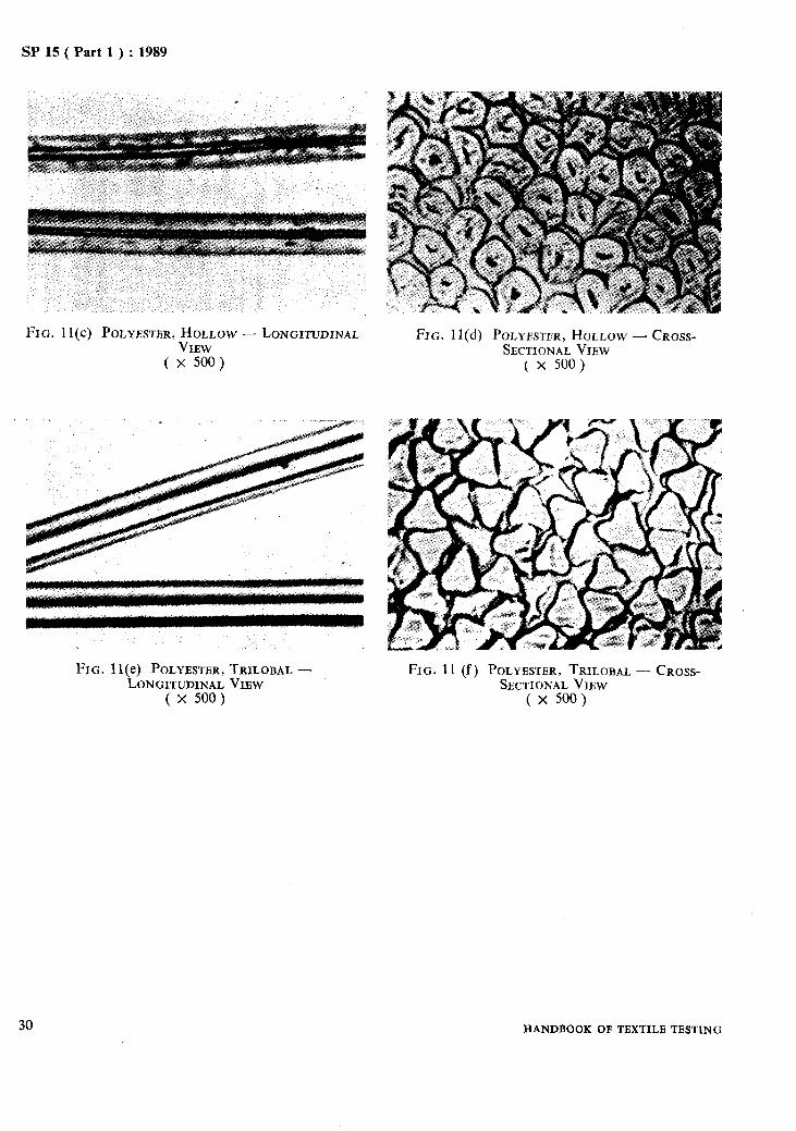
The methods described in this standard are simple and are meant for a rapid identification of the more common textile fibres of commerce. These methods are expected to be especially useful to organizations with only limited testing facilities. The methods prescribed here also invlove the use of a microscope, its value in the identification of fibres cannot be over- emphasized. When one is available, it should always be used for the examination of longi- tudinal and cross-sectional views which are often used in confirmatory tests. Successful identification of fibres depends on experience and familiarity with textile fibres generally. It
is desirable, therefore, to have authentic samples of fibres available for reference pur- poses and the analyst should first make himself familiar with the behaviour of authentic samples before making an attempt to identify unknown samples. The general appearance and colour of the material frequently indicate whether more than one type of fibre is present, and special care should be taken with fibres of different colours.
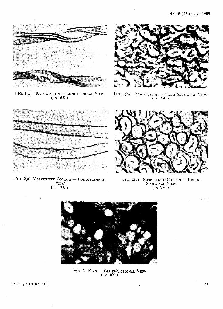
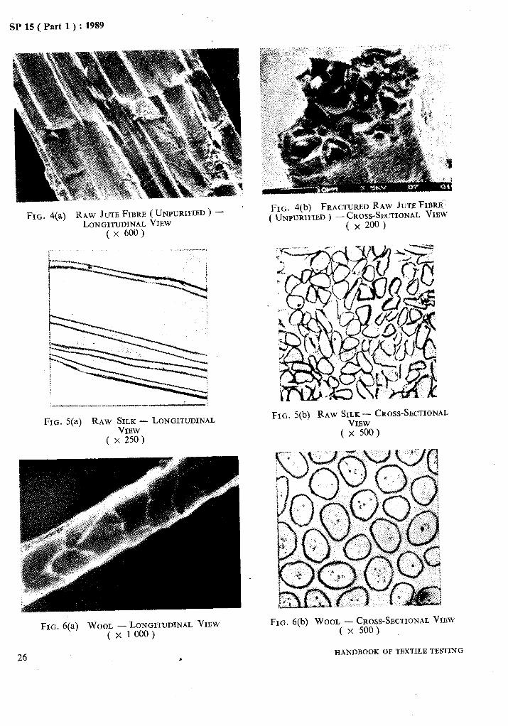
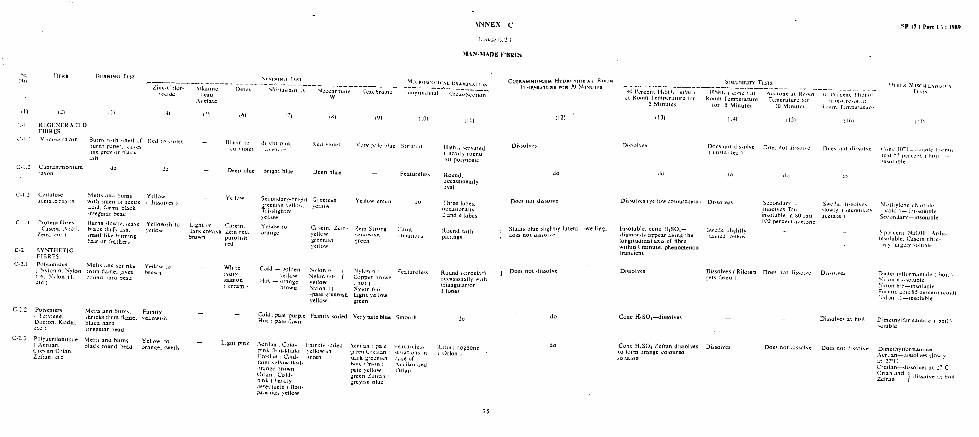
Microphotographs of some important fibres are given in Fig. 1 to Fig. 11.
1 SCOPE
1.1 This standard prescribes methods of tests for identification of textile fibres. Some of them which are included in this standard are listed below:
Group 1 - Natural Fibres
a) Vegetable Fibres
1) Seed Fibres - Cotton, Akund and Kapok \
2) Bast Fibres:
i) Low Lignin Content - Linen or Flax (raw and bleached) and Ramie
ii) High Lignin Content -Jute, Mesta, Roselle, True Hemp and Sunn Hemp
3) Leaf Fibres - Manila Hemp and Sisal
4) Fruit or Nut-Fibres - Coir
b) Animal Fibres ( Natural Protein Fibres )
1) Wool and Chlorinated Wool
2) Silk
i) Cultivated Silk - raw, degummed and weighted
ii) Tasar or Tussah Silk
c) Mineral Fibres
.l) Asbestos
Group 2 - Man-Made Fibres
a) Regenerated Fibres
1) Cellulosic - Viscose, Cuprammonium, Cellulose Acetate ( secondary and
PART 1, SECTION B/ 1
triacetate ), Polynosic, High-Wet Mo- dulus Fibres ( HWM )
2) Protein - Casein, Groundnut Fibre, Zein
b) Synthetic Fibres
1) Polyamides - Nylon 66, Nylon 610, Nylon 6, etc
2) Polyester-Terylene, Terene, Dacron, etc
3) Polyvinyl Derivatives
i) Polyvinyl Chloride - Pe Ce, Rho- vyl, etc
ii) Polyvinyl Chloride Acetate - Vin- yon ST, Vinyon HH
iii) Polyvinyl Chloride - Acrylonitrile - Vinyon N, Dyne1
iv) Polyacrilonitrile ( Acrylic fibres ) - Orlon, Acrilan
v) Polyvinyl Alcohol - Vinylon, Kuralon
vi) Polystyrene and Copolymers -- Styroflex, Polyfil, etc
vii) Polyvinylidene Chloride and Copo- lymers - Saran, Velon
4) Polyolefins
i) Polyethylene .- Polythene
ii) Polypropylene - Reevon
Group 3 - Inorganic Fibres
a) Glass
b) Metal
21

L.._
SP 15 ( Part 1 ) : 1989
2 PREPARATION OF TEST SPECIMEN
2.1 If the sample consists of more than one kind of fibres, separate by dissection the differ- ent kinds, teasing them apart by dissecting needles.
2.2 In order to avoid interference with proper identification of fibres, remove the non-fibrous matter.
3 APPARATUS
3.1 The apparatus for microscopic examination shall consist of a compound microscope, dis- secting needles, glass slides, cover glasses and a cross-sectioning device. The microscope should be equipped to permit examination ‘from 100X to 500x.
4 REAGENTS
4.0 Quality of Reagents
Unless specified otherwise, pure chemicals shall be employed in tests and distilled water shall be used where the use of water or distilled water as a reagent is intended.
NOTE - ‘Pure chemicals’ shall mean chemicals that do not contain impurities which affect the experimen- tal results.
4.1 Zinc Chlor-iodide Solution
Dissolve 20 g of zinc chloride in 10 ml of water. To this solution, add a solution of 2-l g of potassium iodide and 0.1 g iodine in 5 ml of water. Filter or decant the mixture when settled and add a crystal of iodine before stor- ing the mixture in a dark bottle.
4.2 Phloroglucinol and Hydrochloric Acid Solu- tion
Dissolve 2 g of phloroglucinol in 100 ml of alcohol. When required for use, mix with equal volume of concentrated hydrochloric acid.
4.3 Cuprammonium Hydroxide Solution
4.3.1 Solution A
Dissolve 502 g of copper sulphate ( analytical quality ) in 1 000 ml of hot distilled water and cool the solution until crystallization begins. Add 250 g of ice and 450 ml of ammonia of specific gravity 0.880. Make up the volume to 2 700 ml.
4.3.2 Solution B
Prepare a solution of 7.5 ml of 76” Tw caustic soda solution free from carbonate and 72.5 ml of ammonia of specific gravity, 0.880.
4.3.3 When required for use, mix 150 ml of Solution A and Solution B.
22
4.4 Alkaline Lead Acetate Solution
Dissolve 2 g of sodium hydroxide in 30 ml of water and add this to a solution of 2 g of lead acetate in 50 ml of water. Boil the mixture until it becomes clear, cool, make up the volume to 100 ml and filter, if necessary.
4.5 Sulphoric Acid
80 percent ( m/m ).
4.6 Sodium Hydroxide
(i) 5 percent ( m/m ), (ii) 15 percent ( m/m ).
4.7 Nitric Acid
(i) concentrated, (ii) 5 percent ( m/m ), (iii) 25 percent ( m/m ).
4.8 Hydrochloric Acid
concentrated.
4.9 Acetone
4.10 Phenol
90 percent ( mjm ).
4.11 m-Cresol
4.12 Carbon Disulphide
4.13 Tetrahydrofurane
4.14 Dimethylformamide
4.15 Benzene
4.1.6 Cyclohexanone
4.17 Hydrofluoric Acid
4.18 Calcium Hypocblorite Solution
3.5 g/ 1 available chlorine.
4.19, Alcohol Solution
92 percent ethyl alcohol solution ( m/m ).
4.20 Ammonia Solution
4.21 Methyl Salicylate
4.22 Iodine-Potassium Iodide Solution
Prepared by dissolving 20 g iodine in 100 ml of saturated potassium iodide solution ( about 150 g of potassium iodide in 100 ml of distilled water ).
4.23 Sodium Hypochlorite
5.25 percent [ expressed in g/l in available chlorine 1.
4.24 Formic Acid
concentrated.
4.25 Methylen? Chloride
HANDBOOK OF TBXTILB TPSTING
SP 15 ( Part 1 ) : 1989
4.26 Cblorobenzene
4.27 Tolnene
4.28 Glacial Acetic Acid
4.29 Decalin
5 TESTS
5.1 Burning Test
A small tuft of fibres is held by forceps in the frame of a micro-burner for about 10 seconds and is then removed. It is noted whether the tuft burns or not; whether it forms any bead or whether the ash skeleton is retained; the type of smell emitted during burning is also noted. The test is carried out in daylight.
NOTE - The burner should be set up away from draughts as far as possible, but no elaborate screen- ing of the flame is necessary.
5.2 Twist on Drying
One end of a single fibre is held between the fingers and the free end is directed towards the observer. This free end is then moistened and the direction of twist during drying is noted, that is, whether movement is in a clockwise or counter-clockwise direction.
5.3 Floatation Test
A small sample of the fibre after degreasing in benzene-methanol mixture ( 3 : 2 ) is placed in the test liquid and pushed below the surface by means of a glass rod. The liquid should be illuminated transversely and viewed against a black background to observe whether the sample floats on the surface or sinks.
5.4 Swett’s Test
The sample is degreased and immersed in nas- cent chlorine water for 30 seconds, washed in water and alcohol, and then exposed to fumes from strong ammonia; the colour developed is noted.
5.5 Microscopic Analysis
5.5.1 For Longitudinal Examination
Place a small number of fibres on a glass slide in a suitable mounting medium, cover the fibres with a covering glass. Examine the fibres at a specified magnification under microscope.
5.5.2 For Cross-Section Examination
Take a tuft of fibres and prepare the specimen with the cross-sectioning device, place it on a glass slide in a suitable mounting medium and cover it with a covering glass. Examine the fibres at a specified magnification under micro- scope.
5.6 Staining Test
Dye a small tuft of fibre with a mixture of dye- stuffs ( for example, Shirlastain A, Detex, Fibre Stain, etc ) for 3 to 5 minutes and wash thoro- ughly. The colour developed may be viewed carefully or compared with the known dyed samples.
NOTES .
1 The sample is immersed in Detex for about 5 minutes at room temperature with occasional stirring. It is then rinsed several times in water at 50°C until the water remains clear.
2 The sample is thoroughly wetted and washed free from wetting aaent. if anv and then immersed in Shrilas&n A at room temperature for one minute. It is then thoroughly washed in cold water.
3 The sample is wetted in alcohol, washed and immersed in Neocarmine W for 3 to 5 minutes at room temperature. It is then thoroughly rinsed in running water, immersed in dilute ammonia and rins- ed again.
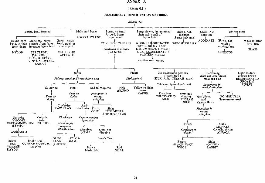
6 PROCEDURE
6.1 For preliminary identification of fibres, follow the scheme given in Annex A. Also examine the sample for staple length to distin- guish continuous filament silk and rayon from staple fibres such as viscose staple fibre.
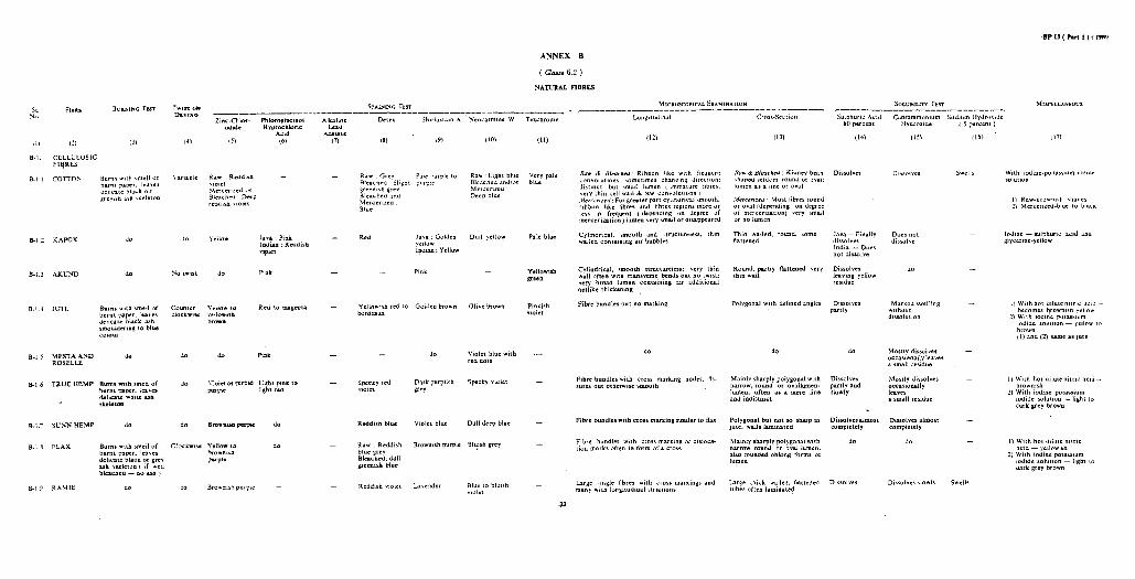
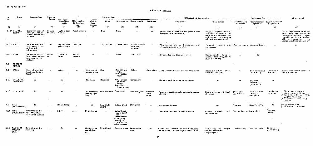
6.2 For confirmation of the indication given by test as prescribed under 6.1, follow the scheme prescribed for individual fibre in Annexes B, C or D.
6.3 For ultimate identification of the fibre under test, repeat the relevant tests, side by side, on both, its specimen and on authentic specimen of the fibre indicated by 6.1 and 4.2.
NOTE - It is necessary that before concluding the final identity of the fibres, the inferences given on various tests should be considered.
PART 1, SECTION B/l 23

As in the Original Standard, this Page is Intentionally Left Blank
)*’ __-__.-__-_--_
b
SP 15 ( Part 1 ) : 1989
FIG. l(a) RAW COTTON -- LONGI’KJDINAL VIEW ( x 500 )
FIG. I(b) RAW C~,~TON -- CROSS-SECTIONAL VIEW ( x 750)
FIG. 2(a) MERCERIZED COTTON - LONGITUDINAL VIEW
( x 500 )
FIG. 2(b) MERCERIZED COTTON - CROSS- SECTIONAL VIEW
( x 750)
FIG. 3 FLAX - CROSS-SECTIONAL VIEW ( x 100)
25 PART 1, SECTION B/l
SP 15 ( Part 1 ) : 1989
FIG. 4(a) RAW JUTE FIBRE (.UNPURIFIED) - LONGITUDINAL VIEW
( x 600)
FIG. 5(a) RAW SILK - LONGITUDINAL VIEW
( x 250)
FIG. 6(a) WOOL -LONGITUDINAL VIEW ( x 1 000 )
FIG. 4(b) FRACTUREDRAW JUTEFIBRB:: ( UNPURIFIED) -buss-$CTIONAL VIEW
X
FIG. 5(b) RAW SILK- CROSS-SECTIONAL VIEW
( x 500)
FIG. 6(b) WOOL -CROSS-SECTIONAL VIEW ( x 500)
HANDBOOK OFTBXTILB TESTING 26 9
Sf 15 ( Part 1 ) : 1989
FIG. 7 ACETATE RAYON-CROSS-SECTIONAL VIEW ( x 320)
_...
FIG. 8(a) VISCOSB,NORMAL -LONGITUDINAL VlEW
(x500)
FIG. S(c) HOLLOW VISCOSE - Viscose FIRRR ( x 2000)
PART 1, SECTION B/l
FIG. 8(b) Vrscos~,No~~~~-CROSS-SECTIONAL
( x 750)
FIG. 8(d) TRILOBAL VISCOSE-LONGITUDINAL VIEW ( x 2 000)
27

SP 15 ( Part 1 j : 1989
FIG. 8(e) CRIMPED VISCOSE - LONGITUDINAL FIG. 8(f) IN~ZATED VISCOSE - LONGITUDINAL
VIEW VIEW
(x1500) ( x 1000)
FIG. 8(g) VISCOSE,POLYNOSIC - LONGITUDINAL FIG. 8(h) VISCOSE, POLYNOSIC - CROSS-SECTIONAL VIBW VIBW
( x 500) ( x 750)
“,.,
.
F1G.9(a) ACRYLIC, BEAN SHAPB -LONGITUDINAL VIBW
( x 500)
FIG. 9(b) ACRYLIC, BEAN SHAPB -- CROSS- SECTIONAL VIEW
( x 500)
28 HANDBOOK Ok: TBXTILE TESTING

SP 15( Part 1):1989
FIG. 10(a) NYLON 6 - LONGDUDINAL VIEW
( x 250)
FIG. 10(b) NYL(JN 6 -CROSS-SECTIONAL VIEW
( x 500)
FIG. 10(c) NYLON, TRILOBAL - CROSS-SECYIONAL VIEU ( x 320)
_.
FIG. 11(a) POLYESTBR,RBGULAR(CIRCULAR) - LONGITUDINAL VIEW
( x 500)
PART 1, SIXTION B/1
FIG. 11(b) POLYESTER, REGULAR (CIRCULAR j - CROSS-SECTIONAL VIEW
( x 500)
29
SP 15 ( Part 1) : 1989
FIG. 11(c) POLYESTER, HOLLOW -- LONGITUDINAL VIEW
( x 500)
FIG. 11(e) POLYESTER,TRILOBAL - LONGITUDINAL VIEW
( x 500)
30
FIG. 11(d) POLYESTER, HOLLOW-CROSS- SECTIONAL VIEW
( x 500)
FIG. 11 (f) POLYESTER, TRILOBAL -- CROSS- SECTIONAL VIEW
( x 500)
HANDBOOK OF TEXTILE TESTING
SP 1s ( Part 1) : 1989
ANNEX A
( Clause 6.1 )
PRELlMINARY IDENTIFICATION OF FIBRES
Burning Test I
I Burns, &ad formed
I I
Round hard Melts’and burns, I
Burns, black bead, shrinks shrinks from flame bead, smell of
from flame irregular black bead acetic acid I I
NYLON TERYLENE, CEL;ULOSE DACRON, ACETATE
Pe Ce, RHOVYL, VINYON. DYNEL.
I Melts and burns Burns, ‘no bead
I I Burns slowly, lerives black Burn:, Ash
I Chars, Ash Do not burn
POLYEkHYLENE formed, burnt fltiy ash, smell of skeleton skeleton I
uauer smell burnt hair Bdrnt hair smell I ., / - _ I ALGINATE Glow; but
CELLULOSIC FIBRES WOOL. CHLORINATED WEIGHLED SILK WOOL, SItK ( RAW
reta& Melts to clear
hard bead I
Floatation in alcohol DEGUMMED), TUSSAH original form
ASBASTOS GL!4SS
( 92 percent ) SILK, REGENER.~TED / PROTEIN FTRRES I I ,
Alkaline lead acetate
I I I 1
SiAks Fldats No blacken&g possibly Light to dark I I
Phloroglucinol and hydrochloric Shirlastain A ( light grey )
Blackening Wool and chlorinated
acid SILK AND TUSSAH SILK greyish brown
wool and hair REGENERATED
I_ Magenta ’ ’ ’ Cold cone hyd!-ochloric acid
I PROTEIN Appearance in FIBRES
Colourless Pink Yellow to light I methylsalicylate
I Twis; on AKUND brown
KAPOK I
Floatation in Dissolves Doks not I
Twist on drying methyl CULTIVATED dissolve Med?llated NO MED’ULLA drying I salicylate SILK TUSSAH and Transparent wool
ClockLise Adti- / I SILK Kempy Hairs
-1 I RAW FLAX clockwise Floats Sinks Floatation in
COIR JUTE, MESTA
No !wist -1 7 AND ROSELLAS
methyl- salicylate
Variable Clockwisb Cuprammonium VISCOSE, twist / hydroxide
I CUPRAMMONIUM COTTON Mean staple I
RAYON length of Floats Silks
ultimatejibres I
I Dissolves I MOHAIR
Shirla;tain A Does not
I Floatation in CAMEL HAIR
I HEMP dissolve alcohol ALPACA / I
&ight 1 30 km 120lmm S,ver:‘s Test Brig t Blue FLAX RAMIE
pink CUPRAMMONIUM (Bleached) I
VISCOSE RAYON RAYON
B&l Rkd MANILA SISAL
I
I Floats
BLACK FACE WOOL
Sinks ANGORA RABBIT
31

As in the Original Standard, this Page is Intentionally Left Blank

- - - -
_ _ _ _ Kurdan- \I&,
- - - -
- - - _ _
- - _ - do
SP 15 ( Part 1) : 1989
%. FIBRE BURNING
(1)
D-l.
(2) (3)
Asbestos Glows, does n ot Very-fine, fibre-like - - burn crystal of varying
diameter (easily separated ), fairly regular over fibre length
D-2. Glass
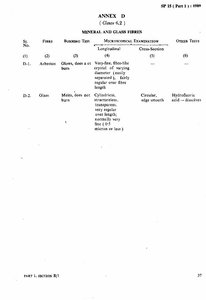
ANNEX D
( Clause 6.2 )
MINERAL AND GLASS FIBRES
TEST MICROSCOPICAL EXAMINATIOM OTHER TESTS r---------- h__________~
Longitudinal Cross-Section
(4) (5) (6)
Melts, hoes not Cylindrical, burn structureless,
transparent, very regular over length; normally very fine ( 0.5 micron or less )
Circular, edge smooth
Hydrofluoric acid - dissolves
PART 1, SECTION B/l 37

As in the Original Standard, this Page is Intentionally Left Blank
SP 15 ( Part 1 ) : 1989
SECTION C '
QUANTITATIVE CHEMICAL ANALYSIS OF TEXTILE FIBRES I

As in the Original Standard, this Page is Intentionally Left Blank

SP 15 ( Part 1) : 1989
RECOMMENDED METHODS FOR THE REMOVAL OF NON-
FIBROUS MATTER PRIOR TO QUANTITATIVE ANALYSIS
OF FIBRE MIXTURES
( Source : IS 9068 : 1979 )
It is common practice for various additions to be made to fibres, yarns and fabrics for assisting
quantitative chemical analysis of fibre mixtures
the processing and manufacture or modifying given in various Indian Standards.
the properties of the finished material. These usually result in appreciable increases in mass The removal of certain types of non-fibrous and often affect the solubility of the fibres. It matter, particularly when more than one subs- has also to be borne in mind that fibres gener- tance is present, may demand the exercise of ally contain a small proportion of naturally considerable chemical resource, and each occurring non-fibrous substances. The removal material to be treated for removal of its non- of these non-fibrous substances is therefore fibrous matter should be regarded as an indivi- necessary before conducting the procedure for dual problem.
1 SCOPE
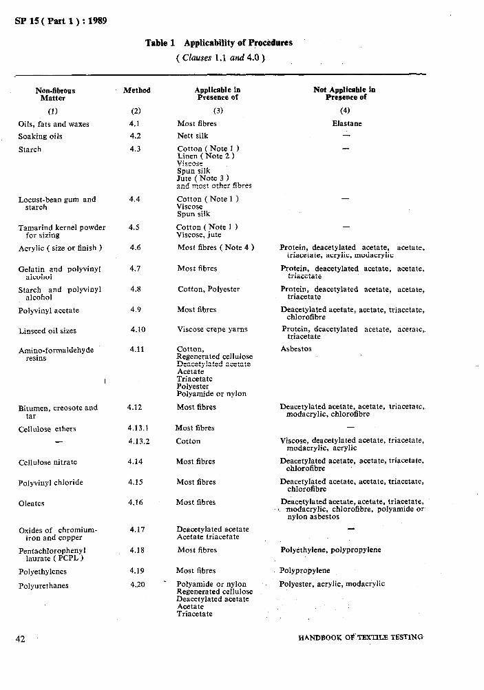
1.1 This standard prescribes recommended pro- cedures for the removal of certain commonly found types of non-fibrous matter from the fibres. The fibres to which the procedures arc applicable are also listed in Table 1.
1.2 Identification of the non-fibrous matter and of the fibres present has not been covered in this standard. In certain cases, the complete elimination of all the added matter like com- pounds which react with the fibre substrate is impracticable. The quantity remaining should not affect the quantitative analysis. On the other hand it is essential to minimize the chemi- cal degradation of the fibres.
2 PRINCIPLE
2.1 Wherever possible, non-fibrous matter is removed by a suitable solvent. But in many cases the removal of certain finishes involve some chemical modification of the finish. More over chemical degradation of the fibre substance cannot always be avoided.
3 APPARATUS
3.1 The apparatus required is part of the normal equipment of a chemical laboratory.
I 4 PROCEDURES
4.0 When the type of finish present on the material is known, the applicable procedures as given in 4.1 to 4.24 shall be followed for remo- val of non-fibrous matter. In case the type of finish is not known, the procedures as given in Appendix A shall be folIotied. Information regarding the applicability and non-applicability of the procedures as given in 4.1 to 4.24 in the presence of certain fibres is given in Table 1.
PART 1, SBCTIOH c/l
4.1 Oils, Fats and Waxes
Extract the specimen in ._ _ a Soxhlet apparatus with benzene-methyl alcohol mixture ( 3 : 2 ) for 2 hours at a minimum rate of 6 cycles per hour.
4.2 Soaking Oils
Extract the specimen in a Soxhlet apparatus with toluene-methanol mixture ( 1 : 3 ) for 2 hours at a minimum rate of 6 cycles per hour.
4.3 Starch
Immerse the specimen in a freshly prepared solution containing O-1 percent by mass of a non-ionic wetting agent together with an appropriate amylase preparation using a liquor to specimen ratio of 100 : 1. The concentration of the amylase preparation and the pH, tem- perature, and time of treatment should be those recommended by the manufacturer. Transfer the specimen to boiling water and boil it for 15 minutes. Test for complete removal of starch using a dilute aqueous solution of iodine in potassium iodide. When all the starch is remov- ed rinse the specimen in potassium iodide and finally thoroughly in water, squeeze or mangle and dry it.
4.4 Locust-Bean Gum and Starch
Boil the specimen in water for 5 minutes using a liquor/specimen ratio of 100 : 1. Repeat this procedure with a fresh portion of water. Follow this by the procedure described in 4.3.
4.5 Tamarind Seed Size
Boil specimen in one percent solution of sodium carbonate for 30 minutes using liquor
41
Y _ _ ~~~~
SP15(P%wl):1989
Table 1 Applicability of Procedures
( czuuses 1.1 and 4.0 )
Oils, fats and waxes
Soaking oils
Starch
Loc;c;hbean gum and 4.4
Tamarind kernel powder for sizing
4.5
Acrylic ( size or finish ) 4.6
Geal;;Ehomd polyvinyl
St;;;iho;nd polyvinyl
Polyvinyl acetate
Linseed oil sizes
Amino-formaldehyde resins
Bitumen, creosote and tar
Cellulose ethers
Cellulose nitrate 4.14 Most fibres
Polyvinyl chloride 4.15 Most fibres
Oleates 4.16 Most fibres
Oxides of chromium- iron and copper
Pentachlorophenyl laurate ( PCPL 1
Polyethylenes
Polyurethanes
42
Method
(2)
4.1
4.2
4.3
Applicable in Presence of
(3)
Most fibres
Nett silk
Cotton ( Note 1 ) Linen ( Note 2 > Viscose Spun silk Jute ( Note 3 1 and most other fibres
Cotton ( Note 1 ) Viscose Spun silk
Cotton (Note 1 ) Viscose, jute
Most fibres ( Note 4 )
Not Applicable io Presence of
(4)
Elastane
-
-
Protein, deacetylated acetate, acetate, triacetate, acrylic, modacrylic
4.7 Most fibres Protein, deacetylated acetate, acetate, triacetate
4.8 Cotton, Polyester Protein, deacetylated acetate, acetate, triacetate
4.9 Most fibres
4.10
4.11
Viscose crepe yarns
Deacetylated acetate, acetate, triacetate, chlorofibre
Protein, deacetylated acetate, acetate, triacetate
Cotton, Regenerated cellulose &;;%;lated acetate
Triacetate Polyester Polyamide or nylon
Most fibres
Asbestos
4.12 Deacetylated acetate, acetate, triacetate, modacrylic, chlorofibre
4.13.1 Most fibres
4.13.2 Cotton
-
Viscose, deacetylated acetate, triacetate, modacrylic, acrylic
Deacetylated acetate, acetate, triacetate, chlorofibre
Deacetylated acetate, acetate, triacetate, chlorofibre
Deacetylated acetate, acetate, triacetate, t. modacrylic, chlorofibre, polyamide or
nylon asbestos
4.17 Deacetylated acetate Acetate triacetate
4.18 Most fibres Polyethylene, polypropylene
4.19
4.20
Most fibres
Polyamide or nylon Regenerated cellulose Deacetylated acetate Acetate Triacetate
Polypropylene
Polyester, acrylic, modacrylic
HANDBOOK O$.TEXTILB TESTING
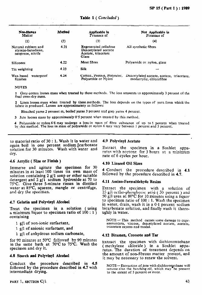
L_. _--- .___ __II_ _._... ._. .-
SP 15 ( Part 1) : 1989
Table 1 ( Concluded)
No;n-~IIS
(1) Natural rubbers and
styrene-butadiene, neoprene, nitrile
Method
(2) 4.21
Applicable in Presence of
(3) Regenerated cellulose Deacetylated acetate Acetate, triacetate Glass
Not Applicable in Presence of
(4) All synthetic fibres
Silicones 4.22
Tin weighting 4.23
WFnib;zd waterpoof 4.24
Most fibres Polyamide or nylon, glass
Silk -
Cotton, Protein, Polyester, Polyamide or Nylon
Deacetylated acetate, acetate, triacetate, modacrylic, chlorofibre
NOTES
I Grey cotton looses mass when treated by these methods. The loss amounts to approximately 3 percent of the final oven-dry mass.
2 Linen looses mass when treated by these methods. The loss depends on the types of yarn from which the fabric is produced. Losses are approximatety as follows:
Bleached yarns 2 percent m, boiled yarns 3 percent and grey yarns 4 percent.
3 Jute looses mass by approximately 0’5 percent when treated by this method.
4 Polyamide or nylon 6’6 may undergo a 10~s in mass of fihre substance of up to 1 percent when treated by this method. The loss in mass of polyamide or nylon 6 may vary between 1 percent and 3 percent.
. to material ratio of 30 : 1. Wash it in water and 4.9 Polyvinyl Acetate again boil in one percent sodium icarbonate solution for 30 minutes. Wash with water and Extract the specimen in a Soxhlet appa-
dry. ratus with acetone for 3 hours at a minimum rate of 6 cycles per hour.
4.6 Acrylic ( Size or Finish )
Immerse and agitate the specimen for 30 minutes in at least 100 times its own mass of solution containing 2 g/l soap or other suitable detergent and 2 g/l sodium hydroxide at 70 to 75°C. Give three 5-minute rinses in distilled water at 85”C, squeeze, mangle or centrifuge, and dry the specimen.
4.7 Gelatin and Polyvinyl Alcohel
Treat the specimen in a solution ( using a minimum liquor to specimen ratio of 100 : 1 ) containing
1 gjl of non-ionic surfactant, 1 g/l of anionic surfactant, and
4.10 Linseed Oil Sizes
4 Conduct the procedure described in 4.1 followed by the procedure described in 4.7.
4.11 Amino-Formaldehyde Resins
Extract the specimen with a solution of 25 g/l ortho-phosphoric acid ( 50 percent ) and 50 g/l urea at 80°C for 10 minutes using a liquor to specimen ratio of 100 : 1. Wash the specimen in water, drain, wash it in a O-1 percent sodium bicarbonate solution, and finally wash it thoro- ughly in water.
NOTE - This method causes some damage to cupr- ammonium, viscose, deacetylated acetate, acetate, triacetate rayons and modal.
for 90 minutes at 50°C followed by 90 minutes
1 g/l of anhydrous sodium carbonate,
in the same bath at 70°C to 75°C. Wash the specimen and dry it.
4.12 Bitumen, Creosote and Tar
the amount of non-fibrous matter present, and it may be necessary to renew the solvent.
Extract the specimen with dichloromtehane ( methylene chloride ) in a Soxhlet appa- ratus. The duration of treatment denends on
4.8 Starch and Polyvinyl Alcohol
Conduct the procedure described in 4.5 followed by the procedure described in 4.7 with intermediate drying.
NOTE-Extraction of jute with dichloroqethane will remove also the batching oil, which may be present to the extent of 5 percent or more.
PART 1, SECTIQN c/1 43

r -..._______--.._.__-..._.__ .-._-..
SF 15 ( Part 1) : 1989
4.13 Cellulose Ethers
4.13.1 Methyl Cellulose.in Cold Water
Soak the specimen in cold. water for 2 hours. Rinse the specimen repeatedly in cold water with vigorous squeezing.
4.13.2 Cellulose Ethers Insoluble in Water But Soluble in Alkali
Immerse the specimen in a solution containing approximately 175 g/l sodium hydroxide at room temperature, or cooled to a temperature of approximately 5 to 10°C for 30 minutes. Then wash the specimen thoroughly in a fresh portion of reagent, rinse it well in water, neutralize it with approximately 0.1 N acetic acid, rinse it again in water and dry it.
4.14 Cellulose Nitrate
Immerse the specimen in acetone at room temperature for 1 hour using a liquor to specimen ratio of 100 : 1. Drain, wash the specimen in three portions of fresh acetone, and allow the entrained solvent to evaporate.
4.15 Polyvinylchloride
Immerse the specimen in tetrahydrofuran at room temperature for 1 hour using a liquor to specimen ratio of 100 : 1. If necessary, scrape off the softened polyvinylchloride. Drain, wash the specimen in three portions of fresh tetrahydrofuran, drain and allow the entrained solvent to evaporate.
NOTE- Because of risk of explosion, tetrahydrofuran should not be recovered by distillation.
4.16 Oleates
Immerse the specimen in approximately N/5 hydrochloric acid at ambient temperature until it is thoroughly wetted. Wash the speci- men well and dry it. Extract the specimen in a Soxhlet apparatus with dichloromethane (methylene chloride ) for 1 hour at a mini-
mum rate of 6 cycles per hour.
4.17 Oxides of Chromium, Iron and Copper
Immerse the specimen in a solution con- taining 14 g/l hydrated oxalic acid at 80°C for 15 minutes using a liquor to specimen ratio of 100 : 1. Wash it thoroughly ( any copper pre- sent will remain as the colourless oxalate; remove this with 1 percent acetic acid at 40°C for 15 minutes and wash the specimen ). Neut- ralize the specimen with ammonia and wash it thorough@ in water. Squeeze, mangle or cen- trifuge, and dry it.
4.18 PeWachlorophenyl Lanrate ( PCPL )
Extract the specimen in a Soxhlet apparatus with toluene for 4 hours at a minimum rate of 6 cycles per hour; -. P_L
GOTE - This method is not applicable if dies con- taining chromiuni have been applied to the material under test.
4.19 Polyethylenes
Extract the specimen in boilink toluene under reflux for 2 hours.
NOTE - The material shall be completely immersed in the boiling solvent.
4.20 Polyurethanes
No completely satisfactory method is. available but the following have been found useful. Some polyurethanes can be removed by solution in dimethyl sulphoxide or dichlorome- thane ( methylene chloride ), and subsequent repeated washing of the sample with fresh quantities of solvent. When the fibre composi- tion of the specimen permits, some polyure- thanes can be removed by hydrolysis in an aqueous solution containing 50 g/l sodium hydroxide and 100 g/l ethanol at a temperature 50 to 60°C for 1 hour.
NOTE - Dimethyl sulphoxide has toxic properties.
4.21 Natural Rubbers, Styrene-Butadiene, Neo- prene, Nitrile and Most Other Synthetic Rubbers
4.21.1 No completely satisfactory method is available but the following have been found useful.
4.21.2 Soak the specimen in a hot volatile solvent which swells it considerably ( for example bepzene ), and when it is fully swollen remove, as much of the rubber as possible by scraping. It may be possible in some cases where the textile fibresare exposed, to wet only the rubber/textile interface, and strip the rubber textile layers apart almost at once. Con- tinue by boiling the residual specimen with constant stirring in 50 or more times its mass of moltenpidichlorobenzene; use a flat-bottomed flask with an attached widebore condenser ( to allow adequate access of air ), and preferably a magnetic stirrer and hotplate.
4.21.3 After 45 minutes add 1 part of 70-percent tributyle hydroperoxide per 4 parts p-dichloro- benzene present. Boil until decomposition of the rubber is complete ( 2 hours is an average time ). Cdol’the flask to about 60°C and add an equal volume of benzene. Eilter and wash the textile component repeatedly in warm benzene.
4.21.4 Nitrile rubber (i.e. acrylonitrile-butadiene rubber ) may.. require the addition of the same volume of nitrobenzene as of tributyl hydro- peroxide to speed up the dissplution process.
44 z HANDBOOK O# TEXTILE TBSTING
NOTES 1 Natural rubber should dissolve after being boiled in p-dichlorobenzene alone for several hours in the presence of air. Solution may also be affected by heating in diphenyl ether at 105°C for 2 hours and then washing the specimen in benzene. 2 The above treatments are strongly oxidative in character and the properties of the textile material may be affected appreciably.
4.22 Silicones
Scour the specimen in a solution containing 50 to 60 ml/l of 40 percent hydrofluoric acid in a polyethylene vessel at 65°C for 45 minutes. Thoroughly wash the specimen, neu- tralize it, and scour it in a solution containing 2 g/l soap at 60°C for 1 hour.
NOTE - Hydrofluoric acid is a dangerous product.
4.23 Tin Weighting ( Silk )
SP 15 ( Part 1) : 1989
Immerse the specimen in N/2 hydrofluoric acid in a polyethylene vessel at 55°C for 20 minutes and stir occasionally. Rinse in warm water. Immerse the specimen in 2 percent solution of carbonate at 55°C for 20 minutes. Wash the specimen in warm water, squeeze, mangle or centrifuge, and dry it.
4.24 Wax-Based Waterproof Finishes
Extract the specimen in a Soxhlet appa- ratus with dichloromethane ( methylene chlo- ride ) for at least 3 hours at a minimum of 6 cycles per hour. Then, to remove any metallic complexes, scour the specimen in a solution containing 10 g/ 1 formic acid and 5 g/l acid- stable surfactant at 80°C for 15 minutes. Wash the specimen thoroughly in water until it is free from acid.
ANNEX A
( Clause 4.0 )
A-l Extract the specimens/samples with benzene- methyl alcohol mixture in 3 : 2 ratio in a Soxhlet apparatus for 2 hours at a minimum rate of 6 cycles per hour. ( This removes oils, fats, waxes, certain thermoplastic resins, etc. )
A-2 Extract the specimens/samples with ethyl alcohol in a Soxhlet apparatus for 2 hours at a minimum rate of 6 cycles per hour. ( This removes soaps, cationic finishes, etc. )
A-3 Treat the specimens/samples with 200 ml of water at 50°C for 30 minutes, stirring occasion-
ally with glass rod or mechnically. Rinse thrice with fresh portion of warm water ( 50°C ) and dry. ( This removes water-soluble materials. )
A-4 Immerse the specimen/sample in 200 ml of 0.1 N hydrochloric acid at 80°C for 25 minutes, stirring gently every 3 minutes. Rinse thorou- ghly with water at 80°C containing a few drops of ammonia and then finally with plain water. Remove excess water from the sample by squeez- mg and suction centrifuging and allow to dry. ( This removes starches/aminoaldehyde ‘corn- pound resins. )
PART 1, SECTION c/l 45

As in the Original Standard, this Page is Intentionally Left Blank

. sP15(Pmtl):1989
BINARY MIXTURES OF JUTE AND ANIMAL FIBRES
(Source: TS 6570 :1972)
Two or more different types of fibres are mixed with one another for producing a variety of textiles. Such a mixture may be composed of different types of man-made fibres or different types of natural fibres or both. The composition of the mixture of textile fibres is governed by the ultimate use to which the textile materials are to be put.
Mixtures of textile fibres are being increasingly used for different purposes. The use of the different fibres in textile mixture has necessita- ted the formulation of standard methods for identification and quantitative estimation of fibres in mixtures. For the textile technologists as well as the traders and the consumers, the quantitative analysis of textile fibres in mixtures is of considerable importance.
1 SCOPE
1.1 It prescribes a method for quantitative chemical analysis of binary mixtures of jute and animal fibres. The animal fibre component may consist solely of hair or wool or mixtures of the two. It is suitable for application to fibres in any textile form, such as fibre, yarn or fabric.
NOTE - Before conducting an analysis accordingto this method, the fibres present in the mixture should be,identified and sample to be analyzed should be freed from all non-fibrous matter. Dye in the dyed fibres is considered to be an integral part of the fibre and is not to be removed.
2 PRINCIPLE
2.1 Sample of mixture is dried and wkighed. The nitrogen content of the mixture is determi- ned and from this and the known or assumed nitrogen contents of the two components, the proportion of each component is calculated.
3 APPARATUS
3.1 Sintered Glass Filter Crucibles
of appropriate capacity with a pore size of 90 to 150 microns ( Porosity 1 ) and fitted with ground-glass stopper. If stoppers are not avail- able, the crucibles should be enclosed in weigh- ing bottles for weighing.
3.2 Desiccator
3.3 Ventilated Oven
for drying samples at 105 + 3°C.
3.4 Analytical Balance
capable of weighing to an accuracy of 0*0002 g.
3.5 Soxhlet Apparatus
3.6 Kjeldahl Distillation Apparatus
It consists of a round bottom flask of 1 000 ml capacity fitted with a rubber stopper through which passes. one end of the ‘bonnecting bulb
tube. The other end of the bulb tube is connec- ted to the condenser by a rubber stopper and the lower end of the condenser is attached by means of a rubber tubing to a dip tube which dips into a beaker of 250 ml capacity.
4 REAGENTS
4.0 Quality of Reagents
Unless specified otherwise, pure chemicals shall be employed in tests and distilled water shall be used where the use of water as reagent is intended.
NOTE- ‘Pure chemicals’ shall mean chemicals that f;enr;tcontain impurities which affect the results of
4.1 Copper Sulphate Pentahydrate
4.2 Selenium Dioxide
nitrogen free.
4.3 Sulphuric Acid
concentrated.
4.4 Standard Sulphuric Acid
0.5 N.
4.5 Potassium Sulphate
nitrogen free.
4.6 Sodium Hydroxide Solution
approximately 40 percent ( w/v ).
4.7 Methyl Red Indicator
Dissolve 1 g of methyl red in 200 ml of rectified spirit.
4.8 Standard Sodium Hydroxide Solution
0.5 N.
4.9 Carbon Tetracbloride
4.10 Ethyl ,Alcohol
PART 1, SECTION c/2 47
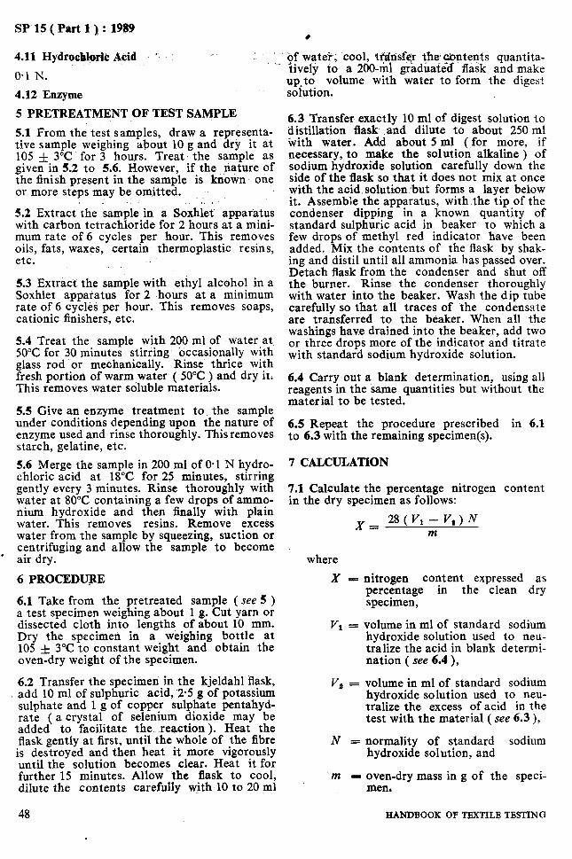
SP 15 ( Part .l ) : 1989
4.11 Hydrochlprh Acid ~
0.1 N.
4.12 Enzyme
5 PRETREATMENT OF TEST SAMPLE
5.1 From the test samples, draw a representa- tive sample weighing about 10 g and dry it at 105 & 3°C for 3 hours. Treat the sample as given in 5.2 to 5.6. However, if the nature of the finish present in the sample is known one or more steps may be omitted.
5.2 Extract the sample in a Soxhlet apparatus with carbon tetrachloride for 2 hours at a mini- mum rate of 6 cycles per hour. This removes oils, fats, waxes, certain thermoplastic resins, etc. .~
5.3 Extract the sample with ethyl alcohol in a Soxhlet apparatus for 2 hours at a minimum rate of 6 cycles per hour. This removes soaps, cationic finishers, etc.
5.4 Treat the sample with 200 ml of water at 50°C for 30 minutes stirring occasionally with glass rod or mechanically. Rinse thrice with fresh portion of warm water ( 50°C ) and dry it. This removes water soluble materials.
5.5 Give an enzyme treatment to the sample under conditions depending upon the nature of enzyme used and rinse thoroughly. This removes starch, gelatine, etc.
5.6 Merge the sample in 200 ml of 0.1 N hydro- chloric acid at 18°C for 25 minutes, stirring gently every 3 minutes. Rinse thoroughly with water at 80°C containing a few drops of ammo- nium hydroxide and then tially with plain water. This removes resins. Remove excess water from the sample by squeezing, suction or centrifuging and allow the sample to become
l air dry.
6 PROCEDUPE
6.1 Take from the pretreated sample ( see 5 ) a test specimen weighing about 1 g. Cut yarn or dissected cloth into lengths, of about 10 mm. Dry the specimen in a weighing bottle at 105 f 3°C to constant weight and obtain the oven-dry weight of the specimen.
6.2 Transfer the specimen in the kjeldahl flask, , add 10 ml of sulphuric acid, ‘2.5 g of potassium
sulphate and 1 g of copper sulphate pentahyd- rate ( a crystal of selenium dioxide may be added to facilitate the reaction ). Heat the flask gently at first, until the whole of the fibre is destroyed and then heat it more vigorously until the solution becomes clear. Heat it for further 15 minutes. Allow the flask to cool, dilute the contents carefully with 10 to 20 ml
48
of wateq, cool, tf$nsfer the contents quantita- lively to a 200-m] graduated flask and make up,to volume with water to form the digest solution.
6.3 Transfer exactly 10 ml of digest solution to distillation flask .and dilute to about 250 ml with water. Add about 5 ml ( for more, if necessary, to make the solution alkaline ) of sodium hydroxide solution carefully down the side of the flask so that it does not mix at once with the acid.solution.but forms a layer below it. Assemble the apparatus, with-the tip of the condenser dipping in a known quantity of standard sulphuric acid in beaker to which a few drops of methyl red indicator have been added. Mix the contents of the flask by shak- ing and distil until all ammonia has passed over. Detach flask from the condenser and shut off the burner. Rinse the condenser thoroughly with water into the beaker. Wash the dip tube carefully so that all traces of the condensate are transferred to the beaker. When all the washings have drained into the beaker, add two or three drops more of the indicator and titrate with standard sodium hydroxide solution.
6.4 Carry out a blank determination, using all reagents in the same quantities but without the material to be tested.
6.5 Repeat the procedure prescribed in 6.1 to 6.3 with the remaining specimen(s).
7 CALCULATION
7.1 Calculate the percentage nitrogen content in the dry specimen as follows:
where
x-
Vr =
v, =
N=
nitrogen content expressed as percentage in the clean dry specimen,
volume in ml of standard sodium hydroxide solution used to neu- tralize the acid in blank determi- nation ( see 6.4 ),
volume in ml of standard sodium hydroxide solution used to neu- tralize the excess of acid in the test with the material ( see 6.3 ),
normality of standard sodium hydroxide solution, and
m - oven-dry mass in g of the speci- men&
HANDBOOK OF TmTILB TESTING
c _-.
’ SP 15 ( Part 1 ) : 1989
7.2 Using the values of 0.22 percent for the where nitrogen content of jute and 16.2 percent for the nitrogen content of animal fibre, both
P, = percentage of animal fibre in the
values being expressed on the dry mass of the clean dry specimen.
fibre, calculate the composition of the mixture 8 REPoRT as follows: 8.1 The report shall include the following
information: x - 0.22
‘, = 16.2 - 0.22 x loo a) Type of material, and b) Percentage of component fibres.
PART 1, SECTION c/2 49

As in the Original Standard, this Page is Intentionally Left Blank
1 SP 15 ( Part 1) : 1989
BINARY MIXTURES OF SILK AND WOOL OR HAIR i
1 ( Source : IS 9889 : 1988 )
*I The use of different fibres blends in textiles has necessitated the formulation
analysis of textile fibres in mixtures is of consi- of standard derable importance to textile technologists,
methods for identification and quantitative esti- traders and consumers. mation of respective fibres. The quantitative
1 SCOPE
1.1 This standard prescribes two methods for the quantitative chemical analysis of binary mixtures of silk and wool or hair in any textile form, such as fibre, yarn and fabric.
NOTE - Before conducting an analysis according to this standard, the fibres present in the mixture should be .identified and the sample to be analysed should be freed from all non-fibrous matter. Dye in the dyed fibre is considered to be an integral part of the fibre and is not to be removed.
NOTE - ‘Pure chemicals’ shall mean chemicals thst do not contain impurities which ‘affect the test results.
3.2 Dilute Sulphuric Acid Solution
5 percent ( m/m ).
3.3 Sulphuric Acid Solution
75 percent ( m/m ).
3.4 Dilute Ammonia Solution
20 percent ( v/v ). 2 APPARATUS
2.1 Conical Flask
3.5 Hydrochloric Acid Solution
28 percent ( m/m ).
of 200 ml minimum capacity, provided with a ground glass stopper.
2.2 Sintered Glass Filter Crucible
of appropriate capacity with a pore size of 90 to 150 microns ( porosity 1 ) and provided with a ground-glass stopper. If stopper is not avail- able, the crucible should be enclosed in weigh- ing bottle for weighing.
2.3 Ventilated Oven
capable of maintaining a temperature of 105” f 3°C.
2.4 Filter Flask
3.6 Dilute Hydrochloric Acid Solution
5 percent ( m/m ).
4 TESTING CONDITIONS
4.1 The test shall be conducted in prevailing atmospheric conditions.
NOTE - Since dry masses are determined, it is not necessary to condition the sample.
5 PREPARATION OF TEST SPECIMENS
with connection to filter pump and adaptor to enable the crucible ( see 2.2 ) to be fitted to it.
2.5 Analytical Balance
capable of weighing to an accuracy of 0~000 2 g.
2.6 Desiccator
5.1 From the sample, after removing size and finishes draw a respresentative sample weighing about 2 to 3 g. Cut the yarn into pieces and dissect the cloth into yarn pieces of about 10 mm length.
6 METHOD 1
6.1 Principle
containing self-indicating silica gel or anhy- drous calcium’chloride. ‘. 2.7 Mechanical Shaker
The silk fibre is dissolved from a known dry mass of the mixture with 75 percent (m/m ) sulphuric acid ( see Note ). The residue is collected, washed, dried and weighed; its mass corrected if necessary, is expressed as a per- centage of the dry mass of the mixture. The percentage of silk is found by difference.
3 REAGENTS NOTE - Wild silk, such as tussah, does not comple- tely dissolve in 75 percent ( m/m ) sulphuric acid.
3.1 Quality af qeagents
Unless specified otherwise, pure chemicals shall be employed in tests and. distilled water shall be used where the use of water as a reagent is intended.
6.2 Procedure
6.2.1 Take a specimen weighing about 1 g from the pretreated sample (see 5.1). Dry the pieces in weighing bottle at 105 & 3°C to cons- tant mass, cool it in a dessicator and obtain the oven dry mass of the specimen.
PART 1, SECTION C/3 51

SP 15 ( Part 1 ) : 1989
NOTE -The mass shall be taken as constant if the difference between any two successive weighings at an interval of 20 minutes does not exceed 0’1 per- cent.
6.2.2 Put the specimen in a glass-stoppered conical flask. Add 100 -ml of sulphuric acid solution per gram of the specimen, insert the stopper, shake vigorously (preferably in a mechanical shaker ) and allow to stand for 30 minutes at room temperature. Shake again and allow to stand for 30 minutes. Shake a last time and filter the contents of the flask through the weighed filter crucible. Wash any remaining fibres from the flask with a little sulphuric acid solution. Drain the crucible by suction and wash the residue on the crucible successively with 50 ml of dilute sulphuric acid solution, 50 ml of water and 50 ml of dilute ammonia solution. Each time, allow the fibres to remain in contact with the liquid for about 10 minutes before applying suction. Finally, rinse with water, leaving the fibres in contact with the water for about 30 minutes. Drain the crucible by suction, dry the crucible and residue at 105 f 3°C temperature; and cool and weigh them.
6.2.3 Repeat the procedure prescribed in 6.2.1 and 6.2.2 with the remaining test specimen(s).
6.3 Calculations
6.3.1 Method Based on Clean Dry Mass
Calculate the percentage (P) of clean dry insoluble component by the formula:
P _ 100 x ml x d - m.
where
ml = the dry mass of the residue; d = the correction factor of variation
in mass of the insoluble compon- ent in the reagent; and
m, = the dry mass of the specimen.
NOTE - The value of d is found to be 0’975.
6.3.2 Method Based on Clean Dry Mass with Per- centage Addtions for Moisture
Calculated the percentage ( PM ) of clean inso- luble component with percentage additions for moisture, by the formula:
1OOxPx 1+&-
pm= p(1+&)
( >
+ (loo-P)( 1++)
where
Paa = percentage, by mass, of wool or hair fibre in the test sample on dry mass with moisture allow- ance;
P = the percentage of clean dry insoluble compdnent;
b = the percentage addition for mois- ture to the insoluble component; and
a = the percentage addition for mois- ture to the soluble component.
NOTES
1 The following values for standaI’d moisture’regain of various fibres may be considered:
Fibre Standard Moisture Regajn, Percent
Silk 11’0 Wool 13’6
2 The standard moisture regain values are generally accepted as the commercial moisture regain values in the trade.
6.3.3 Method Based on Clean Dry Mass with Per- centage Additions for Moisture Non-fibrous Matter
Calculate the percentage ( Pa ) of clean insolu- ble component in the mixture with percentage additions for moisture and non-fibrous matter by the following formula ( see also Notes 1 and 2 under 6.3.2 ):
.
1OOxPx [
as+& 1+ - Pa=
100 3
Px 1+ [I
*]+(loo-P)[l+ a*] -
where
P = the percentage of clean dry insolu- ble component;
al = the percentage addition for mois-. ture to the soluble component;
a, = the percentage addition for mois- ture to the insoluble component;
b 1= the percentage addition for non- fibrous matter to the soluble com- ponent; and
b a= the percentage addition for non- fibrous matter to the insoluble component.
NOTE - The percentage- additions for non-fibrous matter may be as agreed to between the buyer and the seller.
6.4 Determine the percentage of silk fibre by difference.
7 METHOD 2
7.1 Principle
The silk fibre is dissolved from a known’ dry mass of the mixture with 28 percent ( m/m ) hydrochloric . acid. The residue is collected, washed, dried and weighed; its mass corrected if necessary, is expressed as a percentage of the
HANDBOOK’OF TElXTILE TESTING- 52
SP 15 ( Part 1 ) : 1989
dry mass of the mixture. The percentage of silk is found by difference.
7.2 Procedure
7.2.1 Follow the procedure given in 6.2.1.
7.2.2 Put the specimen in a glass-stoppered conical flask. Add 100 ml of hydrochloric acid solution per gram of the specimen, insert the stopper, shake vigorously ( preferably in a mechanical shaker ) and allow to stand at room temperature for 30 minutes. Shake a last time and filter the contents of the flask through the weighed filter crucible. Wash any remaining fibres from the flask with a little hydrochloric acid solution. Drain the crucible by suction and wash the residue on the crucible successively with 50 ml of dilute hydrochloric acid solution, 50 ml of water and 50 ml of dilute ammonia solution. Each time, allow the fibres to remain in contact with the liquid for about 10 minutes before applying suction. Finally, rinse with water, leaving the fibres in contact with the water for about 30 minutes. Drain the crucible by suction, dry the crucible and residue at
105 & 3°C temperature, and cool and weigh them.
7.2.3 Repeat the procedure prescribed in 7.2.1 and 7.2.2 with the remaining test specimen(s).
7.3 Calculations
Calculate the percent of component fibres in the mixture as prescribed in 6.3.1, 6.3.2, 6.3.3 and 6.4 taking the value of correction factor d as 1.00.
8 REPORT
8.1 The report shall include the following:
a) Nature of material tested; b) Method used ( see 6 or 7 ); c) Method of calculation used ( see 6.3 and
7.3 ); d) Number of specimens tested; and e) The percentage of component fibres in
the mixture ( individual and average ).
FART 1, SECTION C/3 53

As in the Original Standard, this Page is Intentionally Left Blank
SP 15, ( Part 1) : 1989
BINARY MIXTUTES OF REGENERARED CELLULOSE FIBRES AND COTTON, SODlUM ZINCATE METHOD
[ Source : IS 1889 ( Part 1 ) : 1976 ]
The use of different fibre blends in textile has necessitated the formulation of standard methods for identification and quantitative esti- mation of respective fibres. The quantitative
analysis of textile fibres in mixtures is of consi- derable importance- to textile technologists, traders and consumers.
1 SCOPE 4 REAGENTS
I.1 It prescribes sodium zincate method for quantitative chemical analysis of binary mix -
4.0 Quality of Reagents
Unless specified otherwise, pure chemicals shall be employed in the test and distilled water shall be used where the use of water as reagent is intended.
tures of regenerated cellulose fibres and cotton in any textile form, such as fibre, yarn or fabric.
NOTE - Before conducting an analysis according to this method the fibres present in the mixtures should be identified and the sample to be analysed shall be freed from all non-fibrous matter. Dye in the dyed fibres is considered to be an integral part of the fibre and is not to be removed.
1.2 This method is not applicable to mixtures , in which the cotton has suffered extensive
chemical degradation, nor when the viscose, cupro or modal fibre 1s rendered incompletely soluble by the presence of certain permanent finishes or reactive dyes that cannot be removed completely.
2 PRINCIPLE
2.1 A specimen of the mixture is dried and weighed. The regenerated cellulose fibres in the test specimen are dissolved in sodium zincate solution. The residue ( cotton) is collected, washed, dried and weighed and the proportion of regenerated cellulose and cotton is calcu- lated.
3 APPARATUS
3.1 Sintered Glass Filter Crucibles
of appropriate capacity with pore size’of 90 to 150 microns ( porosity 1 ) and fitted with ground-glass stoppers. If the stoppers are not available, the crucibles should be enclosed in weighing bottles for weighing.
3.2 Conical Flask
of 100 ml capacity, provided with a glass stopper.
3.3 Ventilated Oven
for drying specimens/residue at 105 f 3°C.
3.4 Analytical Balance
of an accuracy of O*OOO 2 g.
PART 1, SECTION C/4 .
NOTE - ‘Pure chemicals’ shall mean chemicals that do not contain impurities which affect the test results.
4.1 Sodium Zincate Solution Take a sample of sodium hydroxide and deter- mine its sodium hydroxide content. Take an equivalent of 180 g of sodium hydroxide and dissolve it in 180 to 200 ml of water in a flask. To this add, with constant stirring, 80 g of zinc oxide. Heat the contents in the flask to almost boiling until clear or slightly turbid solution appears. Cool, add about 200 ml of water, stir thoroughly and make up to 500 ml with water, filter if necessary, and store the resulting solu- tion in a stoppered flask or bottle.
4.2 Ammonia Solution
250 ml of concentrated ammonia solution (sp gr O-88 ) diluted to 1 litre with water.
4.3 Acetic Acid Solution
50 ml of glacial acetic acid diluted to 1 litre with water.
5 PREPARATION OF TEST SPECIMENS
5.1 From each sample after removing size and finishes, draw a representative specimen weigh- ing about 2 to 3 g. Cut the test specimen into pieces of approximately 25 mm length.
6 PROCEDURE
6.1 Take a test specimen to about 0.5 g and put it in a weighing bottle. Dry the specimen in the weighing bottle at 105 f 3°C to a constant mass and obtain oven-dry mass of the speci- men.
6.2 Put the oven-dry specimen in a loo-ml conical flask. Dilute 1 volume of sodium zincate solution with 2 volumes of distilled water and mix thoroughly. Add the diluted solution of
55
sodium zincate to the flask to make a material to liquor ratio of 1 : 150. Shake the contents of the flask v5gorously, at intervals, for 20 minu- tes. Decent the liquid through a sintered glass filter crucible and apply suction to complete filtration.
6.3 Add dilute ammonia solution to the residue in the flask to make a material to liquor ratio of 1: 100. Shake the contents for 5 minutes and again filter and apply suction to complete filtra- tion.
6.4 Wash the residue with dilute acetic acid solution.
6.5 Add water to the residue in the flask, shake and transfer the solution and the residue to the sintered glass filter crucible. Wash out any remaining fibres in the flask with more water and filter the washings through the sintered glass filter crucible. Wash the residue several times with water, drain and apply suction to complete filtration.
6.6 Dry the residue at 105 -f 3°C to a constant mass and weigh. Determine the mass of the residue.
6.7 Similarly carry out the test for other test specimens.
7 CALCULATION
7.1 Calculate the percentage of regenerated cellulose in each test specimen by the following formula and determine the average of all the values:
Percentage of. regeae- rated cellulose _ mn-(mrQx 100
m, where
m, = oven-dry mass in grams of the specimen obtained in 6.1,
m, = oven-dry mass in grams of the residue ( cotton ) obtained in 6.6, and
d = correction factor for the loss in mass sustained by cotton during the analysis.
NOTE - The value of d is found to be 1’02.
8 REPORT
8.1 The report shall include the following information:
a) Type of the material, b) Percentages of regenerated cellulose and
cotton in the mixture, and c) Number of specimens tested.
56 HANDBOOK OF TBXTILB TESTING

SP 15 ( Part 1) : 1989
BINARY MIXTURES OF REGENERATED CELLULOSE FIBRES AND COTTON, CADOXEN SOLVENT METHOD
[ Source : IS 1889 ( Part 2 ) : 1976 ]
The use of different fibre blends in textiles has analysis of textile fibres in mixtures is of consi- necessitated the formulation of standard derable importance to textile technologists, methods for identification and quantitative traders and consumers. estimation of respective fibres. The quantitative
1 SCOPE
1.1 It prescribes Cadoxen solvent method for quantitative chemical analysis of binary mix- tures of regenerated cellulose fibres and cotton in any textile form, such as fibre, yarn or fabric.
NOTE - Before conducting an analysis according to this method, the fibres present in the mixture should be identified and the sample to be analysed shall be freed from all non-fibrous matter. Dye in the dyed fibres is considered to be an integral part of the fibre and is not to be removed.
1.1.1 This method is not applicable to mixtures in which the cotton has suffered extensive chemical degradation, nor when the viscose, cupio or modal fibre is rendered incompletely
’ soluble by the presence of certain permanent finishes or. reactive dyes that cannot be removed completely.
2 PRINCIPLE
2.1 A sample of the mixture is dried and weighed. The regenerated cellulose fibres in the sample are dissolved in Cadoxen solvent. The residue, that is, cotton, is collected, washed, dried and weighed and the proportion of regene- rated cellulose and cotton is calculated.
3 APPARATUS
3.1 Sintered Glass Filter Crucibles
of appropriate capacity ,with pore size of 90 to 150 microns (porosity 1 ) and fitted with ground-glass stoppers. If the stoppers are not available, the crucibles should be enclosed in weighing bottles for weighing.
3.2 Desiccator
with phosphorus pentoxide as desiccant.
3.3 Analytical Balance
of an accuracy of 0.000 2 g.
3.4 Conical Flask
of 150 ml capacity, provided with a glass stopper.
3.5 Ventilated Oven
for drying specimensjresid ue at 105 k 3%.
PART 1, SBCTIQN C/4
4 REAGENTS
4.1 Cadoxen Solvent
containing 4.6 f 0.1 percent cadmium and 28 percent ethylenediamine.
4.1.1 Method of Preparation
Dilute freshly distilled ethylenediamine with distilled water to 28 percent ( m/m ). Cool the solution below 0°C. To this slowly add 8 percent cadmium oxide under vigorous stirring over a period of 4 hours, after which continue stirring for 2 hours. Keep the solution in cold storage ( 0 to 5°C ) for a period of 60 hours and then slowly bring it to room temperature ( 30°C ). Filter the solvent through sintered glass cruci- ble and analyse for ethylenediamine and cad- mium contents as given in Annex A.
4.2 Light Petroleum
boiling range 40 to 60°C.
5 PREPARATION OF TEST SPECIMENS
5.1 From each sample after removing size and finishes, draw a representative specimen weigh- ing about 2 to 3 g. Cut the test specimen into pieces of approximately 25 mm length.
6 PROCEDURE
6.1 Take about 25 g of the specimen in weigh- ing bottle and dry at 105 & 3°C for 3 hours, cool over phosphorus pentoxide in a desiccator and weigh. Transfer the contents to 150-ml stoppered flask and determine the exact mass of the specimen by weighing the bottle again.
6.2 Add 50 ml of Cadoxen solvent to the flask and shake the flask at room temperature for 1 hour. Filter the contents through a weighed sintered glass crucible.
6.3 Wash the residue ( undissolved cotton ) with 10 ml of Cadoxen solvent, and then give several washes with distilled water till the wash- ings are free of cadmium. Dry the crucible with residue at 105 f 3°C for 3 hours, cool over phosphorus pentoxide in a desiccator and weigh. Determine the mass of the residue.
6.4 Similarly carry out the test for other test specimens.
57
SP 15 ( Part 1) : 1989
7 CALCULATION mass in grams of the specimen
7.1 Calculate the percentage of cotton fibre in m’ - ( 6.1 ).
the specimen by the following formula for each NOTE - Since cotton fibre does not undergo any
test specimen and find out the average of all loss in mass under above conditions, no correction factor is necessary.
the values: 8 REPORT
100 x m, Percentage of cotton = ---- ma
8.1 The report shall include the following information:
a) Type of the material, where b) Percentages of regenerated cellulose and
m, = mass in grams of the residue cotton in the mixture, and ( 6.3 ), c) Number of specimens tested.
ANNEX A
( Czause 4.1.1 )
METHODS FOR DETERMINATION OF ETHYLENEDIAMINE AND CADMIUM CONTENTS IN CADOXEN SOLVENT
A-l DETERMINATION OF ETHYLENEDIAMINE CONTENT
A-l.1 Weigh accurately about 5 g of the Cado- xen solvent, dilute in water and make up to 100 ml in a,volumetric flask ( solution A ).
A-l.2 Titrate a 20-ml aliquot of solution A pre- pared as in A-l.1 with 0.5 N sulphuric acid in the presence of methyl orange indicator.
A-l.3 Calculation
Ethylenediamine, percent by mass
= YxNx+~X+ m
vxNxl5 = m
where
v .= volume in millilitres of sulphuric acid consumed,
N = normality of sulphuric acid, and m = mass in grams of the sample taken
for the test.
A-2 DETERMINATION ON CADMIUM CONTENT
A-2.1 Pipette out 20 ml of solution A ( A-l.1 ) and add two-thirds the quantity of 0.5 N sulph-
uric acid required in titration as in A-l.2 in order to keep pH at a proper level for getting a sharp end-point. Add a pinch of indicator mixture ( 2.5 g eriochrome black T + 1.0 g methyl red + 200.0 g sodium chloride ) and 2 ml of buffer solution (350 ml ammonia, 25 per- cent + 54 g ammonium chloride ). Add 20 ml of distilled water and titrate the mixture with 0.05 M EDTA solution to be standardized against 0.05 M cadmium acetate ( analytical reagent grade ) till the colour changes from wine-red to bright green.
A-2.2 Calculation
Cadmium content, percent by mass
100 =vxMx- 100 2. x m x 0.112 4
56.2 =vxMx-&--
where
v = volume in millilitres of 0.05 M EDTA solution consumed,
M = molarity of EDTA solution, and
m = mass in grams of the sample taken for the test.
58
.
HANDBOOK OF TEXTILE TESTING

SP 15 ( Part 1 ) : 1989
BINARY MIXTURES OF REGENERATED CELLULOSE F’IBRES AND COTTON, FORMIC ACID-ZINC CHLORIDE METHOD
[ Source : IS 1889 ( Part 3 ) : 1979 ]
The use of different fibre blends in textiles has analysis of textile fibres in mi\.tures is of consi- necessitated the formulation of standard derable importance to textile technologists, methods for identification and quantitative traders and consumers. estimation of respective fibres. The quantitative
1 SCOPE
1.1 It prescribes formic acid-zinc chloride method for quantitative chemical analysis of binary mixtures of regenerated cellulose fibres and cotton in textile form, such as fibre, yarn or fabric.
NOTE - Before conducting an analysis according to this method, the fibres present in the mixture should be identified and the sample to be analysed shall be freed form all ‘non-fibrous matter. Dye in the dyed fibres is considered to be an integral part of the fibre and is not to be removed.
1.1.1 This method is not applicable to mixtures in which the cotton has suffered extensive chemical degradation, nor when the viscose, cupro or modal fibre is rendered incompletely soluble by the presence of certain permanent finishes or reactive dyes that cannot be removed completely.
2 PRINCIPLE
A sample of the mixture is dried and weighed. The regenerated cellulose fibres in the sample are dissolved in formic acid-zinc chlo- ride reagent. The residue ( cotton) is collected, washed, dried and weighed; and the proportion of regenerated cellulose and cotton is calcu- lated.
3 APPARATUS
3.1 Sintered Glass Filter Crucibles
of appropriate capacity with pore size of 90 to 150 microns ( porosity 1 ) and fitted with ground-glass stopper. If the stoppers are not available, the crucibles should be enclosed in weighing bottles for weighing.
3.2 Conical Flask
6.1 Take a test specimen weighing about O-5 g and put it in a weighing bottle. Dry the speci- men in the weighing bottle at 105 & 3°C to constant mass and obtain oven-dry mass of the specimen.
of 100 ml capacity provided with a glass stopper
3.3 Analytical Balance
of an accuracy of O*OOO 2 g.
4 REAGENTS
6.2 Put the oven-dry specimen without any delay in a loo-ml glass-stoppered conical flask preheated to 7O”C, and add to it 50 ml of formic acid-zinc chloride reagent also pre-heated to 70°C. Stopper the flask, shake it and keep it in a thermostatically controlled bath at 70 f 20°C for 20 minutes. During this period, shake the flask a couple of times. Filter the contents through a tared sintered glass crucible avoiding the transfer of residue.
4.0 Quality of Reagents
Unless specified otherwise, pure chemicals shall be employed in tests and distilled water shall be
6.3 Wash the residue ( undissolved cotton) thoroughly with water at 40% by decantation. Add 100 ml dilute ammonia solution and keep for 10 minutes. Filter through the crucible under suction, wash with water and dry the residue at 105 f 3°C to constant mass.
PART 1, SECTION. c/4 -- ; 59.
used where the use of water as a reagent is intended.
NOTE - ‘Pure chemicals’ shall mean chemicals that do not contain impurities which affect the test results.
4.1 Formic Acid-Zinc Chloride Reagent
Dissolve 20 g of anhydrous zinc chloride (analy- tical reagent quality ) and 68 g of anhydrous formic acid in water and make up to 100 g specific gravity l-367. If anhydrous formic acid is not available, equivalent quantity of 80 to 85 percent formic acid may be used.
4.2 Dilute Ammonia Solution
20 ml of concentrated ammonium hydroxide ( specific gravity O-88 ) made up to one litre with water.
5 PREPARATION OF TEST SPECIMENS
From each sample after removing size and finishes draw a representative specimen weigh- ing about 2 to 3 g. Cut the test specimen into pieces of approrrimately 25 mm length.
6 PROCEDURE

SP 15 ( Part 1) : 1989
7 CALCULATION
Calculate the percentage of cotton fibre in I each test specimen by the following formula
and determine the average of all the values:
Percentage of cotton = 100 x M, x d
MB where
M, = mass of residue obtained in 6.3, M s = mass of specimen obtained in 6.1,
and d = correction factor for the loss in
mass sustained by cotton during the analysis.
NOTE - The value of d is found to be 1’06 for raw cotton and 1’02 for bleached cotton.
8 REPORT
The report shall include the following informa- tion:
a) Type of the material; b) Percentage of :
1) regenerated cellulose, 2) cotton; and
c) Number of specimens tested.
60 HANDBOOK OF TEXTILE TESTING

SPlS(Partl): 1989
BINARY MIXTURES -OF REGENERATED CELLULOSE FIBRES AND COTTON, SULPHURIC ACID METHOD
[ Source : IS 1889 ( Part 4 ) : 1979 ]
Two or more different types of fibres~ are mixed the formulation of standard methods, for identi- with one another for producing variety of fication and quantitative estimation of the fibres. textiles for different purposes. The use of differ- Such an evaluation is of interest to the textile cnt types of fibres in mixture has necessitated technologists, traders and consumers.
1 SCOPE
1.1 It prescribes sulphuric acid method for quantitative chemica! analysis of binary mix- tures of regenerated cellulose fibres and cotton in any textile form, such as fibre, yarn or fabric.
NOTE - Before conducting an analysis according to this method the fibres present in the mixtures should be identified and the sample to be analysed shall be freed from all non-fibrous matter. Dye in the dyed fibres is considered to be an integral part of the fibre and is not to be removed.
1.2 This method is not applicable to mixtures in which the cotton has suffered extensive chemical degradation, nor when the viscose, cupro or modal fibre is rendered incompletely soluble by the presence of certain permanent finishes or reactive dyes that cannot be removed completely.
2 PRINCIPLE
2.1 A sample of the mixture is dried and weighed. The regenerated cellulose fibre is dis- solved in sulphuric acid solution. The residue, that is cotton, is collected, washed, dried and weighed. Then the proportion of regenerated cellulose and cotton is calculated.
3 APPARATUS
3.1 Sintered Glass Filter Crucibles
of appropriate capacity with pore size of 90 to 150 microns ( porosity 1 ) and fitted with ground-glass stoppers. If the stoppers are not available, the crucibles should be enclosed in weighing bottles for weighing.
3.2 Ventilated Oven
capable of maintaining 105 f 3°C.
3.3 Analytical Balance
of an accuracy of O-000 2 g.
4 REAGENTS
4.0 Quality of Reagents
a temperature of
Unless specified otherwise, pure chemicals shall be employed in tests and distilled water shall be
used where the use of water as a reagent is intended.
NOTE - ‘Pure chemicals’ shall mean chemicals that do not contain impurities which affect the test results.
4.1 Sulphuric Acid Solution
60 percent ( m/m ) ( specific gravity 1,493 at 27°C ).
4.2 Sulphuric Acid ( Dilute Solution )
10 percent ( m/m ).
4.3 Ammonia ( Dilute Solution )
2 percent ( m/m ). Dilute 20 ml concentrated ammonium hydroxide ( specific gravity 0.88 ) to one litre with water.
5 PREPARATION OF TEST SPECIMENS
5.1 From the sample, after removing size and finishes draw a representative specimen weigh- ing about 2 to 3 g. Cut the test specimen into pieces of approximately 25 mm length and divide it into two.
6 PROCEDURE
6.1 Take a test specimen weighing about 1 g from the pretreated sample ( see 5 ). Cut the specimen to small pieces of about 2 mm length. Dry the specimen to specimen in a weighing bottle at 105 k 3°C to constant mass and obtain the oven-dry mass of the specimen.
6.2 Transfer the specimen to a flask containing 100 ml of sulphuric acid ( 60 percent ) at room temperature, and stir vigorously to break up the sample completely at the first instant and then stir intermittently. Shake thoroughly, pre- ferably with a mechanical shaker for 30 minutes and then transfer the contents of the flask to a weighed sintered glass crucible, wash the resi- due remaining in the flask, using a little more sulphurci acid solution, and transfer the contents to the crucible. Wash the residue twice with a small quantity of dilute sulphuric acid solution followed by distilled water. Then wash the residue with dilute ammonia solution and finally wash the residue thoroughly with water. After each washing, drain the crucible with the aid of suction. Dry the residue to a
61
SP 15 ( Part 1) : 1989
constant mass in an oven at 105 f 3”C, cool and weigh.
6.3 Similarly carry out the test on the other test specimen.
7 CALCULATION
7.1 Calculate the percentage of cotton fibre in each test specimen by the following formula and determine the average :
Percentage of cotton = 100 x M, x d
M* where
M, = mass of residue obtained in 6.2, d = correction factor for the loss in
mass sustained by cotton during the analysis, and
Ma - mass of specimen obtained in 6.1.
NOTE - The value of d is found to be 1’05.
7.2 Determine the percentage of regenerated cellulose fibre by difference.
8 REPORT
The report shall include the following infor- mation:
a) b)
4
Type of material, Percentage of:
1) regenerated cellulose, 2) cotton, and
Number of specimens tested.
‘62 HANDBOOK 6F TBXTILB TESTING
Sl;l5 ( Part 1) : 1989
BINARY MIXTURES OF CELLULOSE TRIACETATE AND CERTAIN OTHER FIBRES
( source : IS 1564 : 1988 )
The use of different fibre blends in textiles has analysis of textile fibres in mixtures is of consi- necessitated the formulation of standard derable importance to the textile technologists, methods for identification and quantitative traders and consumers. estimation of respective fibres. The quantitative
1 SCOPE
1.1 This standard prescribes a method for quantitative chemical analysis of binary mix- tures in any textile form, such as fibre, yarn or fabric of cellulose triacetate with cotton, wool, silk, regenerated cellulose, regenerated protein, polyamide, polyester, acrylic and glass fibres.
NOTE - Before conducting an analysis according to this standard, the fibres present in the mixture should be identified and the sample to be analysed should be freed from all non-fibrous matter. Dye in the dyed fibres is considered to be an integral part of the fibre and is not to be removed.
2 PRINCIPLE
2.1 A sample of the mixture is dried and weighed. The cellulose triacetate in the sample is dissolved. in dichloromethane (‘methylene chloride ). The residue, that is, the insoluble component is collected, washed, dried and weighed; its mass, ,corrected if necessary, is expressed as a percentage of the dry mass of the mixture. The percentage of triacetate is found by difference. , , ,
‘. 3 APPARATUS
3.1 Conical Flask. b ‘.
of 200 I& minimum, capacity, provided with a ground-glass-stopper. 1
3.2 Sintered Glass Filter Crucible
of appropriate capacity with pore ‘size of 90 to 150 microns ( porosity 1 ) and fitted with ground-glass stopper is not available, the cruci- ble should be enclosed in Weighing bottle for weighing. j
3.3 Ventilated Oven
for drying samples at 105’ & 3°C
3.4 Filter Flask
with connection to mter -pump and adaptor to enable the crucible (3.2). to be fitted to it.
3.5 Analytical Balance
capable of weighing to -an aecutacy of ,@OOO 2 g.
3.6 Desiccator
containin& self-indicating silica gel or anhy- drous calcium chloride.
3.7 Mechanical Shaker
4 REAGENTS
4.0 Quality of Reagents
Unless specified otherwise, pure chemicals’shall be employed in tests and distilled water shall be used where the use of water as a reagent is intended.
NOTE - ‘Pure chemicals shall mean chemicals that do not contain imuurities which affect the test results.
4.1 Dichloromethane ( Methylene’Chloride )
CAUTION ,A -
This reagent being toxic, needs full precautions during its use.
5 TESTING CONDITIONS
The test shall be conducted in prevailing atmos- pheric conditions.
NOTE - Since dry masses are determined, it is not necessary to condition the sample.
6 PREPARATION &? TEST SPECIMENS
From the sample, after removing size and finishes draw, a representative sample weighing about 2 to 3 g. Cut the yarn into pieces and dissect the cloth into yarn pieces of about 10 mm length.
7 PROCEDURE
7.1 Take a test spe,cimen weighing about 1 g from the pretreated sample ( see 6.1 ). Dry the specimen kept in ‘a weighing bottle in the drying oven at 105 f 3°C to, constant mass and obtain the oven-dry m,ass of the specimen.
NOTE - The mass shall be-taken as constant if the difference between any two successive weighings at an interval of 20 minutes does not exceed 0’1 percent.
7.2 To the specimen contained in the conical flask,. add 100 ml of dichloromethane per gram of the specimen. Insert’ the stopper, shake the
PART 1, aCTION <c/s, i.:. _ 63
SP15(Partl):l!m
flask to wet. out the specimen, and allow the flask to staxid for 30 niifititei, shaking it at int&i- vals of about 10 minutes. Decant the Iiq$d through the weighed filter crucible. Add 80 ml of dichloromethane to the residue in the flask, shake it by hand, and filter the contents of the flask through the filter crucible. Transfer any residual fibres to the crucible washing out the flask with a little mare dichloromethabe. Drain the crucible with suction, refill the crucible with dichloromethane and allow it to drain under gravity. Finally, drain the crucible with suction, dry the crucible and residue at 105 f 3°C to constant mass, cool in a desiccator and weigh them.
7.3 Similarly carry out the test’ on the other specimen(s).
7.4 Calculations
Calculate the result on a clean dry mass .basis as in 7.4.1 or clean dry mass with percentage additions for moisture as in 7.4.2. or on clian dry mass with percentage additions for moisture and non-fibrous matter as in 7.4.3.
7.4.1 Methqd Based on Clean Dry Mass
Calculate the percentage ( P ) of clean dry in- soluble compoqnt by the formula:
P 100 x ml x d
= m0
where
m0 - dry mass of the specimen;
ml t dry mass of the residue; and
d = correction factor of variation in mass of the insoluble compo- nent in the reagent.
NOTES
1 The value of d is found to be 1’01.
2 In the case of triacetate that is not comple- tely soluble in the reagent, the percentage of triacetate calculated in the normal manner should be multiplied by 1’02. The percentage of triacetate thus calculated should be deducted from 100 to give the percentage of the other fibre.
7.4.2 Method Based on. Clean Dry Mass with Percentage, Additions for MoGture
Calculate the percentage ( Paa ) of clean insolu- ble component with percentage additions for moisture, by the formula:
Prd - P
---wbere !. -.. .
_ .: .” . . . .
\ P = percentage of clean dry insoluble cbrhpbnent,
a F percentage addition for moisture to the soluble component, and
b== percentage addition for moisture to thd insoluble component.
NOTES 1 The following values for standard moisture regain of various fibres may be considered:
Fibre Standard Moisture Regain ( Percent )
Aramid ( safety apparel fabrics )
i=otton Polyamide ( nylon ) Polyester Regenerated protein Silk Textile g[ass Triacetate ( primary ) Viscose rayon ( regenerated
cellulose ) Wool
4’5
8’5 4’5 0’4
10’0 11’0
Zero 3’5
13’0
13’6
2 The standard moisture regain values are generally accepted as the commercial moisture regain values in the trade.
7.4.3 Method Based on Clean Dry Mass with Percentage Additions for Moisture and Non-fibrous Matter
Calculate the percentage ( PA ) of clean insolu- ble component in the mixture with percentage additions for moisture and non-fibrous matter by the following formula ( see also Notes 1 and 2 under 7.4.2 ):
‘lOOxPx[l+ a*-J
pA =G[ I+q$~)+,‘oo-‘)[I+“]
where P = percentage of clean dry insoluble
al =
a, =
bl =
bS =
component, percentage addition for moisture to the soluble component,
percentage addition for moisture to the insoluble component,
percentage addition for non- fibrous matter to the soluble com- ponent, and
percentage addition for non- fibrous matter to the insoluble component.
NOTE - The percentage additions for non-fibrous matter may,be as agreed to between the buyer and the seller.
64 HANDBOOK OF TFXTIL3 TBSTING

c -. ~-. - ..-^
7.4.4 Find out the percentage of soluble compo- nent by subtracting the value obtained in 7.4.1, 7.4.2 or 7.4.3 from 100.
8 REPORT
The report shall include the following:
a) Nature of material to be tested;
b)
c)
d)
SP 15 ( Part 1)
Method of calculation used ( see 7.4.2 or 7.4.3 );
Number of specimens tested; and
: 1989
7.4.1,
The percentage of component fibres in the mixture (individual and average ).
,
PART 1, SECTION c/s 65

As in the Original Standard, this Page is Intentionally Left Blank

SP 15 ( Part 1) : 1989
BINARY MIXTURES OF CELLULOSE ACETATE AND CERTAIN OTHER FIBRES
( Source : IS 2176 : 1988 )
‘The use of different fibre blends in textiles has analysis of textile fibres in necessitated the formulation of standard derable importance to the methods for identification and quantitative esti- traders and consumers. mation of respective fibres. The quantitative
mixtures is of consi- textile technologists,
1 SCOPE
1.1 This standard prescribes two methods for the quantitative chemical analysis of binary mixtures, in any textile form, sue-h as fibre, yarn or fabric of secondary cellulose acetate with cotton, wool, silk, regenerated cellulose, rege- nerated protein, polyamide, polyester, acrylic .and glass fibres.
NOTE - Before conducting an analysis according to this standard, the fibres present in the mixture should be identified and the sample to be analysed should be freed from all non-fibrous matter. Dye in the dyed fibre is considered to be an integral part of the fibre and is not to be removed.
1.2 The methods prescribed in this standard are not applicable to mixtures containing modacrylic fibre, nor to mixtures containing partially acetylated cellulose acetate fibres.
‘2 APPARATUS
‘2.1 Conical Flask
of 200 ml minimum capacity, provided with a ground-glass stopper.
2.2 Sintered Glass Filter Crucible
of appropriate capacity with pore size of 90 to 150 microns ( porosity 1 ) and provided with a ground-glass stopper. If stopper is not availa- ble, the crucible should be enclosed in weighing bottle for weighing.
2.3 Ventilated Oven
.capable of maintaining a temperature of 105 f 3°C.
2.4 Filter Flask
with connection to filter pump and .a.daptor to enable the crucible (2.2) to be fitted to it.
2.5 Analytical Balance
-with an accuracy of PO00 2 g.
2.6 Desiccator
containing self-indicating silica gel or anydrous calcium chloride.
” 2.7 Mechanical Shaker
PART 1, SECTION C/6 y
3 REAGENTS
3.0 Quality of Reagents
Unless specified otherwise, pure chemicals shall be employed in tests and distilled water shall be used where the use of water as a reagent is intended.
NOTE - ‘Pure chemicals’ shall mean chemicals that do not contain impurities which affect the test results.
3.1 Acetone
distilled between 55°C and 57°C.
3.2 Glacial Acetic Acid
distilled at 117°C to 119°C.
CAUTION
Because of harmful effects, full precautions should be taken during its use.
3.3 Dilute Ammonia Solution
Prepared by adding 80 ml of concentrated ammonia solution ( specific gravity O-890 ) to one litre with distilled water.
4 TESTING CONDITIONS
The test shall be conducted in prevailing atmospheric conditions.
NOTE - Since dry masses are determined, it is not necessary to condition the sample.
5 PREPARATION OF TEST SPECIMENS
From the sample, after removing size and finishes draw a representative sample weighing about 1 g. Cut the yarn into pieces and dissect the cloth into yarn pieces of approximately 10 mm length.
6 METHOD 1
6.1 Principle
A sample of the mixture is dried and weighed. The secondary cellulose acetate in the sample is dissolved in acetone. The residue, that is, the insoluble component, is collected, washed,
67
SP 15 ( Part 1) : 1989
dried and weighed; its mass corrected if neces- sary, is expressed as a percentage of the dry
Calculate the percentage ( Paa ) ,of clean insolu- ble component with percentage additions for
mass of the mixture. The percentage of acetate moisture, by the formula: is found by difference.
( b
6.2 PROCEDURE Paa=
1OOxPx 1+ m)
6.2.1 Take one test specimen and dry it in a weighing bottle at 105 f 3°C to constant mass
I+ &)+(loo-PQ+ +)
and determine its oven-dry mass. where NOTE - The mass shall be taken as constant if the difference between any two successive weighings at an interval of 20 minutes does not exceed 0’1 percent.
6.2.2 To the specimen contained in the 200 ml conical flask, add 100 ml of acetone per gram of the specimen, shake the flask to wet out the specimen and allow it to stand for 30 mitutes at room temperature with intermittent shaking and then decant the liquid through the weighed filter crucible. Repeat the treatment twice more ( making three extractions in all ) but for periods of 15 minutes only, so that the total time of treatment in acetone is 1 hour. Wash the residue into the filter crucible with acetone and drain with suction. Refill the crucible with acetone and allow it to drain under gravity. Finally, drain the crucible with suction, dry the crucible and residue at 105 & 3C to constant mass, cool in a desiccator and weigh them.
6.2.3 Repeat the procedure given in 6.2.1 and 6.2.2 for the remaining test specimen(s).
6.3 Calculations
Calculate the mass of the insoluble component as a percentage of the total mass of fibre in the mixture by the methods based on (a) clean dry mass, (b) clean dry mass with percentage addi- tions for moisture, or (c) clean dry mass with percentage additions for moisture and non- fibrous matter as given in 6.3.1, 6.3.2 or 6.3.3 respectively.
6.3.1 Method Based on Clean Dry Mass
Calculate the percentage ( P ) of clean dry insoluble component by the formula:
P = 100 x ml x d
m,
P = the percentage of clean dry insolu- ble component;
a - the percentage addition for mois- ture to the soluble component; and
b - the percentage addition for mois- ture to the insoluble component.
NOTES
1 The following values for standard moisture regain of various fibres may be considered: /
Fibre Standard Moisture ( Regain Percent )
Acetate ( secondary ) 6’5
Acrylic 1’5 Aramid ( safety apparel fabrics 1 4’5 Cotton 8’5 Polyamide ( Nylon ) 4’5 Polyester 0.4 Silk 11’0 Textile glass Zero Viscose rayon ( regenerated 13’0
cellulose ) Wool 13’6
2 The standard moisture regain values are generally accepted as the commercial moisture regain values
in the trade.
6.3.3 Method Based on Clean Dry Mass with Per- centage Additions for Moisture and Non-jbrous Matter
Calculate the percentage ( PA ) ,of clean insolu- ble component in the mixture with percentage additions for moisture and non-fibrous matter by the following formula ( see also Notes 1 and 2 under 6.3.2 ):
where 1ooxP a,+& 1 +-lr 3
m, = the dry mass of the specimen; PA=
4 ,4+b, l+ -rm-’ +(100-P)
3 C 1+ al+& __- ml = the dry mass of the residue; and 100 1
d - the correction factor of variation where in mass of the insoluble compo- nent in the reagent.
P = the pegcentage ofclean dry insolu- ble component;
NOTE -The value of d is found to be 1’00 for all fibres.
aI = the percentage addition for mois- we to th -soluble component;
6.3.2 Method Based on Clean Dry Mass with Per- ccenKtge Additions for Moisture
aa = the percentage addition for mois- ture to the ins&Me component;
68 HANDBOOK DB TEXTILE TBSTING
SP 15( Part 1):1989
bt = the percentage addition for non- fibrous matter to the soluble com- ponent; and
bz = the percentage addition for non- fibrous matter to the insoluble component.
NOTE - The percentage additions for non-fibrous matter may be as agreed to between the buyer and the seller.
6.4 Find out the percentage of soluble compo- nent by difference.
7 METHOD 2
7.1 Principle
A sample of the mixture is dried and weighed. The secondary cellulose acetate in the sample is dissolved in glacial acetic acid. The residue, that is the insoluble component, is collected, washed, dried and weighed, its mass corrected if necessary, is expressed as a percentage of the dry mass of the mixture. The percentage of acetate is found by difference.
7.2 Procedure
7.2.1 Follow the procedure described in 6.2.1 and 6.2.2.
1.2.2 To the specimen contained in the conical flask, add 100 ml of glacial acetic per gram of the specimen. Insert the stopper, shake the flask for 10 minutes on mechanical shaker at room temperature. Decant the supernatant
liquid through the weighed filter crucible. Transfer the residue to the filter crucible, drain with suction and rinse the crucible and residue with 100 ml of glacial acetic acid. Drain the crucible with suction and wash the residue on the filter successively hot water, dilute ammonia solution and finally cold water. After each rinse., allow the liquor to drain through the crucible for 2 minutes before draining with suction. (Do not apply suction until each wash- ing liquor has drained under gravity. ) Dry the crucible and residue at 105 & 3°C temperature to constant mass, cool in a desiccator and weigh them.
7.2.3 Repeat the procedure given in 7.2.1 and 7.2.2 with the remaining test specimen(s).
7.3 Calculations
Calculate the results as described in 8.3.
7.4 Find the percentage of second component by difference.
8 REPORT
The report shall include the following:
a) Nature of material tested, b) Method used ( see 6 or 7 ), c) Method of calculation used ( see 6,3 ), d) Number of specimens tested, and e) The percentage of component fibres in
the mixture ( individual and average ).
PART 1, SECTION C/6 69

As in the Original Standard, this Page is Intentionally Left Blank

SP 15 ( Part 1) : 1989
BINARY ‘MIXTURES OF CELLULOSE TR’IACETATE AND SECONDARY CELLULOSE ACETATE
( Source : IS 2177 : 1988 )
The use of different fibre blends in textiles has necessitated the formulation of standard
tive analysis of textile fibres in mixtures is of
methods for identification and quantitative considerable importance to the textile techno-
estimation of respective fibres. The quantita- logists, traders and consumers.
1. SCOPE
1.1 This standard prescribes two methods for the quantitative chemical analysis of mixtures of cellulose triacetate with secondary cellulose acetate fibres in any textile form, such as fibre, yarn or fabric.
NOTE - Before conducting an analysis according to this standard, the fibres present in the mixture should be identified and the sample to be analysed should be freed from all non-fibrous matter. Dye in the dyed fibre is considered to be an integral part of the fibre and is not to be removed.
2. APPARATUS
2.1 Conical Flask
of 200 ml minimum capacity, provided with a ground-glass stopper.
2.2 Sintered Glass Filter Crucible
of appropriate capacity with a pore size of 90 to 150 microns ( porosity 1 ) and provided with a ground-glass stopper. If stopper is not avail- able, the crucible should b: enclosed in weigh- ing bottle for weighing.
2.3 Ventilated Oven
for drying samples at 105 f 3°C.
2.4 Filter Flask
with connection to filter pump and adaptor to enable the crucible ( see 2.2 ) to be fitted to filter flask.
2.5 Analytical Balance
capable of weighing to an accuracy of 0~000 2 g.
2.6 Desiccator
containing self-indicating silica gel or anhydrous calcium chloride.
2.7 Mechanical Shaker
2.8 Thermostatic Water-bath
PART 1, SBCTION C/7
3. REAGENTS
3.0 Quality of Reagents
Unless specified otherwise, pure chemicals shall be employed in tests and distilled water shall be used where the use of water as a reagent is intended.
NOTE - ‘Pure chemicals’ shall mean chemicals that do not contain impurities which affect the test results.
3.1 Aqueous Acetone Solution
containing 700 ml of acetone ( distilled be- tween 55 and 57°C ) per litre of solution.
3.2 Benzyl Alcohol
3.3 Ethyl Ether \
4 TESTING CONDITIONS
The test shall be conducted in prevailing atmospheric conditions.
NOTE - Since dry masses are determined, it is not necessary to condition the sample.
5 PREPARATION OF TEST SPECIMENS
From the sample, after removing size and finishes, draw a representative sample weigh- ing about 2 to 3 g. Cut the yarn into pieces and dissect the cloth into yarn pieces of about 10 mm length.
6 METHOD 1
6.1 Principle
6.1.1 A sample of the mixture is dried and weighed. The secondary cellulose acetate in the sample is dissolved in 70 percent aqueous acetone solution. The residue, that is, cellulose triacetate, is collected, washed, dried and weighed; its mass corrected if necessary, is expressed as a percentage of the dry mass of the mixture. The percentage of secondary cellu- lose acetate is found by difference.
6.2 Procedure
6.2.1 Take a test specimen weighing about 1 g from the pre-treated sample ( see 5.1 ). Dry the
71

SP 15 ( Part 1) : l9989
specimen kept in a weighing bottle at 105f3”C to constant mass, cool it in a dessicator and weigh it to obtain the clean dry mass of the specimen.
NOTE - The mass shall be taken as constant if the difference between any two successive weighings at an interval of 20 minutes does not exceed 0’1 per- cent.
6.2.2 To the specimen contained in the conical flask, add 80 ml of aqueous acetone per gram of specimen, shake the flask for 1 hour on a mechanical shaker, and then decant the liquid through the weighed filter crucible. Add 60 ml of aqueous acetone to the residue in the flask, shake by hand and decant the liquid through the filter crucible. Repeat this treatment twice more, on the last occasion transferring the fibres to the crucible with aqueous acetone and drain with suction. Refill the crucible with aqueous acetone and allow it to drain under gravity. Finally, drain the crucible with suction, dry the crucible and residue at 105 f 3°C to constant mass, cool in a desiccator and weigh them.
6.2.3 Similarly carry out the test on the other test specimen(s).
6.3 Calculations
Calculate the result on a clean dry mass basis as in 6.3.1 or clean drg mass with percentage additions for moisture as in 6.3.2 or on clean dry mass with percentage additions for moisture and non-fibrous matter as in 6.3.3.
6.3.1 Method Based on Clean Dry Mass
Calculate the percentage ( P) of clean dry insoluble component by the formula:
PC. 100 x ml x d
m. where
m, = the dry mass of the specimen; ml = the dry mass of the residue; and b = the correction factor of variation
in mass of the insoluble compo- nent in reagent.
NOTE - The value of d is found to be 1’01 for all fibres.
6.3.2 Method Based on Clean Dry Mass with Per- centage Addtions for Moisture
Calculate the percentage (PM ) of cIean insolu- ble component with percentage additions for moisture, by the formula:
pbf=
1ooXPX(1+ -&J
P(l+ &)+ (100-P) (1+ -$)
where
P = the percentage of clean dry insolu- ble component;
a = the percentage addition for mois- ture to the soluble component; and
b = the percentage addition for mois- ture to the insoluble component.
NOTES
1 The follqwing values for standard moisture regain of various fibres may be considered:
Fibre Standard Moisture Regain ( Percent )
Acetate ( secondary ) 6’5 Triacetate ( primary ) 3‘5
2 The standard moisture regain values are generally accepted as the commercial moisture regain values in the trade.
6. 3.3 Methcd Eased on Clean Dry Mass with Per- centage Additions for Moisture and Non-
jibrous Matter
Calculate the percentage ( PA ) of clean insolu- ble component in the mixture with percentage additions for moisture and non-fibrous matter by the following formula ( see also Notes 1 and 2 under 6.3.2 ) :
lOOXPX[ 1+*-j
PA= P,[ l+~~]t(loo-P)[ 1+*-j
where
P = the percentage of clean dry insolu- ble component;
al = the percentage addition for mois- ture to the soluble component;
a, = the percentage addition for mois- ture to the insoluble component;
bl = the percentage addition for non- fibrous matter to the soluble com- ponent; and
b, = the percentage addition for non- fibrous matter to the insoluble component.
NOTE - The percentage additions for non-fibrous matter may be as agreed to between the buyer and the seller.
6.4 Find out the percentage of second compo- nent by difference.
7 METHOD 2
7.1 Principle
A sample of the mixture is dried and weighed. The secondary cellulose acetate in the sample is dissolved in benzyl alcohol. The residue, that is the cellulose triacetate, is collected,
72 HANDBOOK OF TEXTILE TESTING
SP 15 ( Part 1) : 1989
washed, dried and weighed; its mass corrected if necessary, is expressed as a percentage of the dry mass of the mixture. The percentage of acetate is found by difference.
7.2 Procedure
7.2.1 Take a specimen weighing about 1 g from the pre-treated sample (see 5.1). Dry the specimen kept in a weighing bottle at 105 f 3°C temperature to constant mass, cool in a dessi- cator and weigh it to obtain the clean dry mass of the specimen.
NOTE - The mass shall be taken as constant if the difference between any two successive weighings at an interval of 20 minutes does not exceed 0’1 percent.
7.2.2 To the specimen contained in the conical flask, add 100 ml of benzyl alcohol per gram of the specimen. Insert the stopper, shake the flask vigorously on the mechanical shaker so that it plunges into the water bath, kept at a temperature of 52 f 2°C. Shake the flask for 20 f 1 minutes at this temperature. Filter the contents of the flask through the weighed filter crucible. Replace the residue in the flask by means of forceps, add to the flask a fresh portion of 100 ml benzyl alcohol and shake as before at a temperature of 52 f 2°C for 20 f 1 minutes. Filter the contents of the flask through the same weighed filter crucible and repeat the cycle a third time with 100 ml of benzyl alco- hol. Pour the liquid and the residue into the
same weighed filter crucible, wash any fibres from the flask into the crucible with an extra quantity of benzyl alcohol at a temperature of 52 f 2°C. Drain the crucible with suction. Transfer the fibres into a flask, rinse with ethyl ether and, after manual shaking, decant through the same tilter crucible. Repeat this rinsing operation three times. Transfer the residue into the same filter crucible. Finally, drain the crucible with suction, dry the crucible and residue at 105 f 3’C to constant mass, cool in a dessicator and weigh them.
7.2.3 Similarly carry out the test on the other test specimen(s).
7.3 Calculations
Calculate the results as given in 6.3, 6.3.1, 6.3.2, 6.3.3 and 6.4.
NOTE - The value of d is found to be 1’00 for all fibres.
8 REPORT
The report shall include the following:
4 b) 4
4 4
Nature of material tested, Method used ( see 6 or 7 ), Method of calculation used ( see 6.3 and 7.3 ); Number of specimens tested, and The percentage of component fibres in the mixture ( individual and average ).
PART 1, SECTION C/7 13

As in the Original Standard, this Page is Intentionally Left Blank

SP 15 ( Part 1) : 1989
BINARY MIXTURES OF NYLON 6 OR NYLON 6.6 FIBRES AND CERTAIN OTHER FIBRES
( Source : IS 2005 : 1988 )
The use of different fibre blends in textiles has analysis of textile fibres in mixtures is of consi- necessitated the formulation of standard methods for identification and quantitative esti-
derable importance to f the textile technologists, traders and consumers.
mation of respective fibres. The quantitative
1 SCOPE .
3 REAGENTS
This standard prescribes two methods. for the quantitative chemical analysis of bmary mixtures of nylon 6 or nylon 6.6 with cotton, regenerated cellulose, polyester, polypropylene, chloro fibre, acrylic or glass fibres in any form, such as fibre, yarn or fabric. It is applicable also to mixtures with wool, but when the wool con- tent exceeds 20 percent, the method prescribed in IS 2006 : 1988 should be followed.
3.0 Quality of Reagents
Unless specified otherwise, pure chemicals shall be employed in tests and distilled water shall be used where the use intended.
of water as reagent is
NOTE - ‘Pure chemicals’ shall mean chemicals that do not contain impurities which affect the test results.
3.1 Formic Acid NOTE - Before conducting an analysis according to this standard, the fibres present in the mixture should be identified and the sample to be analysed should be freed from all non-fibrous matter. Dye in the dyed fibres is considered to be an integral part of the fibre and is not to be removed.
80 percent ( m/m ).
3.2 Dilute Ammonia Solution
2 APPARATUS
Prepared by diluting 80 ml of concentrated ammonia solution ( specific gravity 0890 ) to 1 litre with distilled water.
2.1 Conical Flask
of 200 ml minimum capacity, provided with a ground-glass stopper.
2.2 Sintered Glass Filter Crucible
of appropriate capacity with pore size of 9.0 to 150 microns ( porosity 1 ) and provided with a ground-glass stopper. If stopper is not available, the crucible should be enclosed in weighing bottle for weighing.
2.3 Ventilated Oven
3.3 Hydrochloric Acid
18 percent ( m/m ).
4 TESTING CONDITIONS
The test shall be conducted in prevailing atmospheric conditions.
NOTE - Since dry masses are determined, it is not necessary to condition the sample.
5 PREPARATION OF TEST SPECIMENS
for drying samples at 105 f 3°C.
2.4 Filter Flask
5.1 From the sample, after removing size and finishes draw a representative sample weighing about 2 to 3 g. Cut the yarn into pieces and dissect the cloth into yarn pieces of about 10 mm length.
with connection to filter pump and adaptor to enable the crucible ( 2.2 ) to be fitted to it.
2.5 Analytical Balance
capable of weighing to an accuracy of OWO 2 g.
2.6 Desiccator
6 METHOD 1
6.1 Principle
containing self-indicating silica gel or anhydrous calcium chloride.
2.7 Mechanical Shaker
A sample of the mixture is dried and weighed. The polyamide in the sample is dissolved in 80 percent formic acid. The residue, that is, the insoluble component, is collected, washed, dried and weighed; its mass corrected if necessary, is expressed as a percentage of the dry mass of the mixture. The percentage of nylon 6 or nylon 6.6 is found by difference.
PART 7, SECTION C/8 75

SP 15 ( Part 1) : 1989
6.2 Procedure moisture, by the formula:
6.2.1 Take a specimen weighing about 1 g and dry it in a weighing bottle at 105 f 3°C to constant mass, cool in a desiccator and weigh it to obtain the oven-dry mass of the specimen.
( b
P&l= 1OOxPx 1+ WJ
p ( l+ 100 “)+ (100-P) (1+ *)
NOTE - The mass shall be taken as constant if the difference between any two successive weighings at an interval of 20 minutes does not exceed 0’1 percent.
where
6.2.2 To the specimen contained in the conical flask, add 100 ml of formic acid ( see 3.1) per gram of the specimen, insert the stopper, shake the flask to wet out the specimen and allow the flask to stand for 15 minutes, shaking at inter- vals. Filter the contents of the flask through a weighed filter crucible and transfer any residual fibres to the crucible by washing out the flask with a little mor e formic acid ( see 3.1 ). Drain the crucible with suction and wash the residue on the filter successively with formic acid ( see 3.1 ), hot water, dilute ammonia solution
’ and finally cold water, draining the crucible with suction after each addition. (Do not apply suction until each washing liquor has drained under gravity. ) Finally, drain the crucible with suction, dry the crucible and residue at 105 ;L 3°C to constant mass, cool in a desiccator and weigh them.
P = the percentage of clean dry insolu- ble component;
a = the percentage addition for mois- ture to the soluble component; and
b = the percentage qddition for mois- ture to the insoluble component.
NOTES
1 The following values for standard moisture regain of various fibres may be considered:
Fibre Standard Moisture Regain ( Percent )
6.2.3 Similarly carry out the test with other specimen(s).
6.3 Calculations
Calculate the result on a clean dry mass basis as in 6.3.1 or clean dry mass with percentage
-additions for moisture as in 6.3.2 or on clean dry mass with percentage additions for moisture and non-fibrous matter as in 6.3.3.
Acetate ( secondary ) Acrylic Aramid ( safety apparel
fabrics ) Cotton Modacrylic Polyamide ( nylon ) Polyolifin Polyester Polyvinylidene chloride Polyurethane1 ( spandex ) Silk Textile glass Triacetate ( primary ) Vinyl ( acetal of polyvinyl
alcohol )
6.3.1 Method Based on Clean Dry Mass
Calculate the percentage (P) of clean dry inso- luble component by the formula:
P 100 x m, x d =
m.
where
m, = the dry mass of the specimen;
ml = the dry mass of the residue; and
d = the correction factor of variation in mass of the insoluble compo- nent in the reagent.
NOTE - The value of d is found to be 1’00.
6.3.2 Method Based on Clean Dry Mass with Per- centage Additions for Moisture
Calculate the percentage ( Px ) of clean insolu- ble component with percentage additions for
6’5 1’5 4’5
8’5 0’4 4’5
Zero 0’4
Zero 1’3
11’0 Zero
3’5 4’5
Vinyon ( polyvinyl chloride ) Zero Viscose rayon ( regenerated 13’0
cellulose ) Wool 13’6
2 The standard moisture regain values are generally accepted as the commercial moisture regain values in the trade.
6.3.3 Method Based on Clean Dry Mass with Per- centage Additions for Moisture and Non-fibrous Matter
Calculate the percentage ( PA ) of clean insolu- ble component in the mixture with percentage additions for moisture and non-fibrous matter by the following formula ( see also Notes 1 and 2 under 6.3.2 ):
1OOxPx l+T 1
as+& PA 1 = -
Px 1+* C 1 +(100-P) 1+
[ a#]
76 HANDBOOK Ok TEXTILE TESTING
SP 15 ( Part 1) : 1989
per gram of the specimen. Insert the stopper, shake the flask to wet out the specjmen and allow the flask to stand for 15 minutes at room temperature, shaking at intervals. Filter the contents of the flask through a weighed filter crucible and transfer any residual fibres to the crucible by washing out the flask with a little more hydrochloric acid solution. Drain the crucible with suction and wash the residue on the filter succeessively with hydrochloric acid solution, hot water, dilute ammonia solution and finally cold water, draining the crucible with suction after each addition. ( Do not apply suction until each washing liquor has drained under gravity. ) Finally, drain the crucible with suction, dry the crucible and residue at 105 _I: 3’C to constant mass, cool in a desicca- tor and weigh them.
7.2.3 Repeat the procedure given in 7.2.1 and 7.2.2 with the remaining test specimen(s).
7.3 Calculations
Calculate the percentages of component fibres in the mixture by the methods specified in 6.3.1, 6.3.2, 6.3.3 and 6.3.4.
where
PE the percentage of luble component;
clean dry inso-
al = the percentage addition for mois- ture to the soluble component;
a, = the percentage addition for mois- ture to the insoluble component;
bl = the percentage addition for non- fibrous matter to the soluble com- ponent; and
bs = the percentage addition for non- fibrous matter to the insoluble component.
NOTE - The percentage additions for non-fibrous matter may be as agreed to between the buyer and the seller.
6.3.4 Find out the percentage of second soluble component by difference.
7 METHOD 2
7.1 Principle
A sample of the mixture is dried and weighed. The nylon 6 or nylon 6.6 in the mixture is dis- solved in 18 percent ( m/m ) ( 5.36 N ) ( sp gr at 20°C = 1.087 8 ) hydrochloric acid. The residue, that is the insoluble component, is collected, washed, dried and weighed; its mass corrected if necessary, is expressed as a percen- tage of the dry mass of the mixture. The per- centage of nylon 6 or nylon 6.6 is found by difference.
7.2 Procedure
7.2.1 Follow the procedure described in 6.2.1.
7.2.2 To the sp,ecimen contained in the conical flask, add 100 ml of hydrochloric acid (see 3.3 )
8 REPORT
8.1 The report shall include the following:
a) b) Cl
d) 4
. Nature of material tested; Method used ( see 6 or 7 ); Method of calculation used ( see 6.3 and 7.3 ). Number of specimens tested; and The percentage of component fibres in the mixture ( individual and average ).
PART 1 ) SECTION c/8 77

As in the Original Standard, this Page is Intentionally Left Blank

BINARY MIXTURES OF ACRYLIC, CERTAIN MODACR-Y&@S ._
ANil CERTA!N OTHER FIBRES ( . . I _’ .
The use of different fibre blends in textiles has analysis of textile fibres in mixtures is of consi- necessitated the .formulation of standard derable importance to tbe textile technologists, methods for .identification ’ and quantitative estimation of respective*fibres. The quantitative
traders and consumers. __ : ‘I
I
1 SCOPE
,. ‘,~_, 1
. .
2.6 Desiccator ,i.;
1.1 This -standard presciibss.‘two methods for the quantitative chemical analysis of ‘binary . mixtures of acrylic; modacrylic fibres with wool, silk, cotton, polyamide, polyester, viscose, cupro, modal or glass fibres. It is suitable for application to fibres in any textile form, such as fibre, yarn or fabric: Method 2 is not applicable to acrylic fibr es containing cellulosic fibres, silk and polyamide ( nylon ).
1.2 It is applicable to acrylic fibres dyed with premetalized dyes but not to those dyed with after-chrome dyes. It covers only those moda- crylic fibres which are completely soluble in dimethylformamide ( DME ).
containing self-indicating silica gel or anhy- drous calcium chloride, ‘,
2.7 Mechanical Shaker
3REAGENTS’ ‘,L.’ :
3.0 Quality of Reagents
Unless specified otherwise, pure chemicals shall be employed in tests and distilled water shall be used where the use of water as a reagent is intended.
NOTE - ‘Pure chemicals’ shall mean chemicals that do not contain impurities which affect the test results.
NOTE -Before conducting an analysis according to this standard the fibres present in the mixture should be identified and the sample to be analysed should be
3.1 Dimethylformamlde
freed from all non-fibrous matter. Dye in the dyed fibre is considered to be an integral part of the fibre
boiling point 152 to 154°C.
and is not to be removed. 3.2 Sulplmric Acid Solution
2 APPARATUS 80 percent’( m/m ).
2.1 Conical Flask 3.3 Dilute Sulphuric Acid Solution of 200 ml minimum capacity, provided with a ground-glass stopper.
5 percent ( mlm ).
2.2 Sintered Glass Filter Crucible 3.4 Dilute Ammonia Solution
of appropriate capacity with a pore size of 90 Prepared by diluting 80 ml of concentrated
to 150 microns ( porosity 1) and provided with ammonia solution ( sp. gr. 0.89) to 1 Iitre with
a ground-glass stopper. If stopper is not avail- distilled water_
able the crucible should be enclosed in weighing bottle for weighing.
4 TESTING CONDITIONS,
4.1 The test shall be conducted in prevailing 2<3 Ventilated Oven atmospheric conditions.
for drying samples at 105 f 3’C.
2.4 Filter Flask
NOTE - Since dry masses are determined, it is not necessary to condition the sample.
5 PREPARATION OF ,TEST SPECIMENS with connection to filter pump and adaptor to enable the crucible ( see 2.2 ) to be fitted to it. 5.1 From the sample, aft6 removing size and
finishes draw a representative: sample weighing 2.5 Analytical Balance about 2 to 3 g. Cut ,the yarn into pieces and
capable of weighing.to an accuracy of OWO 2 g. dissect the cloth. into yarn pieces of about 10 mm length.
PART 1, SECTION C/ z
79

SP 15 (Part 1 j :‘I%9
6 METWXWl-.
6.1 Principle
A sample of the mixture is dried and weighed. The acrylic or modacrylic fibres in the mixture are dissolved in dimethylformamide, at 90 to 95°C. The residue, that is, insoluble component, is collected, washed, dried and weighed; its mass, corrected if necessary, is expressed as a percentage of the dry mass of the mixture. The percentage of acrylic or modacrylic is found by difference.
6.2 Procedure
6.2.1 Take a test specimen weighing about 1 g from the pretreated sample ( see 5.1). Dry the specimen in a weighing bottle at 105 f 3°C to constant mass, cool it in a dessicator and obtain the oven-dry mass of the specimen.
NOTE - The mass shall be taken as constant if the difference between any two successive weighings at an interval of.20 minutes does not exceed 0’1 percent.
6.2.4 Repeat the procedbre prescribed in 6.2.1 to 6.2.3 with the remaining test specimen(s).
6.3 Calculations
6.3.1 Method Based on Clean Dry Mass
Calculate the percentage (P) of clean dry inso- luble component by the formula:
PP 100 x ml x d m0
where
m. - the dry mass of the specimen;
ml = the dry mass of the residue; and
d = the correction factor of variation in mass of the insoluble compo- nent in the reagent.
NOTg - Suitable values of d are as follows:
6.2.2 Put all the pieces into a 200-ml conical flask, and add 80 ml of dimethylformamide per gram of the specimen. Insert the stopper, shake the flask to wet out the specimen and heat for 10 minutes at 90 to 95% in a water-bath. Shake gently the contents of the flask five times during this period. Decant the solution through the tared sintered glass filter crucible. Filter the contents of the flask through the filter crucible by means of suction. Add 60 ml of dimethyl- formamide to the residue in the flask, shake by hand and decant the liquid through the filter crucible. Transfer the fibres, remaining in the flask, to the crucible by washing out the .flask with distilled water. Apply suction to the cruci- ble to remove excess water. Wash the residue twice with water by filling the crucible, allowing it to drain under gravity and then draining with suction.
6.2.3 If the residue consists of polyamide or polyester, dry the crucible and residue at 105 f 3°C and cool and weigh them. If the residue is viscose rayon, cotton, silk or wool, transfer it with forceps to a 200-ml conical flask. Add 160 ml of distilled water and shake vigo- rously, intermittently for 5 minutes. Decant through the filter crucible and r epeat the wash- ing process three times more. After the last washing, filter the contents of the flask through the crucible by means of suction. Transfer the fibres remaining in the flask to the crucible by washing with distilled water and apply suction to-the crucible. Dry the crucible and residue at 105 f 3”C, cool in a desiccator and weigh them. Determine the oven-dry mass of the residue.
* 80
Fibre d
Cotton 1’00 Nylon 6 or 6’6 1’01 Polyester 1’02 Silk 1’00 Wool 1’01
Viscose rayon, cupro, modal 1’01
6.3.2 Method Based on Clean Dry Mass with Percentage Additions for Moisture
Calculate the percentage (PM ) of clean insolu- ble component with percentage additions for moisture, by the formula:
P lOOXPX( 1+&)
M- P 1+&-
( )+(100-J-$ I++)
where
P = the percentage of clean dry insolu- ble component;
a = the percentage addition for mois- ture to the soluble component; and
b== the percentage addition for mois- ture to the insoluble component.
NOTES
1 The following values for standard moisture ’ regain of various fibres may be considered:
HANDBOOK OF TEXflLE TESTING

;,
if-
----___._.. -
SP 15 ( Part 1) 1989
Fibre Standard Moisture Regain ( Percent )
Acrylic Aramid ( safety apparel
fabrics ) Cotton Modacrylic Polyamide ( nylon 1 Polyester Silk Textile glass Viscose rayon, cupro, modal Wool
1’50
4’50
8’50 0’40 4’50 0’40
11’00
Zero 13’00
13’60
2 The standard moisture regain values are generally accepted as the commercial moisture regain values in the trade.
6.3.3 Method Based on Clean Dry Mass with Per- centage Additions for Moisture and Non-Jbrous Matter
Calculate the percentage ( Pa ) of clean insolu- ble component in the mixture with percentage additions for moisture and non-fibrous matter by the following formula ( see also Notes 1 and ,2 under 6.3.2 ).
1OOxPx l+T [
W-b~
PA= 1 Pxr 1+*1 +t100-P)[
L
where
P =
al =
a8 =
bl =
the percentage of clean dry inso- luble component;
the percentage addition for mois- ture to the soluble component;
the percentage addition for mois- ture to the insoluble component;
the percentage addition (for non- fibrous matter to the soluble com- ponent; and
b, = the percentage addition for non- fibrous matter to the insoluble component.
NOTE - The percentage addition for non-fibrous matter may be as agreed to between the buyer and the seller.
6.4 Find out the percentage of second compo- nent by difference.
7 METHOD 2
7.1 Principle
A sample of the mixture is dried and weighed. The acrylic or modacrylic fibres in the mixture are dissolved in 80 percent ( m/m ) sulphuric acid solution at room temperature for 30 minutes. The residue, that is, the insoluble com- ponent, is collected, washed, dried and weighed; its mass corrected if necessary, is expressed as a percentage of the dry mass of the mixture. The percentage of acetate is found by difference.
7.2 Procedure
7.2.1 Follow the procedure given in 6.2.1.
7.2.2 Put all the pieces into a 200-ml conical flask and add 100 ml of 80 percent ( m/m ) sulphuric acid ( sp. gr. l-725 ) per gram of the specimen. Insert the stopper, shake the flask to wet out the specimen and allow to stand at room temperature for 30 minutes shaking it at intervals. Filter the contents of the flask through a weighed filter crucible and transfer any residual fibres to the crucible by washing out the flask with a little more sulphuric acid. Drain the crucible with suction and wash the residue on the filter successively with dilute sulphuric acid ( 5 percent ), hot water, dilute ammonia solution, and finally cold water, draining the crucible with suction after each addition. ( Do not apply suction until each washing liquor has drained under gravity. )
7.2.3 Follow the procedure described in 6.2.3.
7.2.4 Repeat the procedure given in 7.211 to 7.2.3 with the remaining test specimen(s).
7.3 Calculations
Calculate the p¢ of component fibres in the mixture as prescribed in 6.3.1, 6.3.2, 6.3.3 and 6.4 taking the value of correction factor d as 0.947 for wool and 1.00 for all other fibres. 8 REPORT
8.1 The report shall include the following: a) Nature of material tested; b) Method used ( see 6 or 7 ); c) Method of calculation used ( see 6.3 or
7.3 ); d) Number of specimens tested; and e) The percentage of component fibres in
the mixture ( individual and average ).
PART 1, SECTION C/9 81

As in the Original Standard, this Page is Intentionally Left Blank

. SP 15 ( Part 1) : 1989
BINARY MIXTURES OF POLYPROPYLENE AND POLYETHYLENE
( Source : IS 11870 : 1986 )
Two or more different types of fibres are mixed with one another for producing a variety of textiles; such a mixture may be composed of different types of man-made fibres or different types of natural fibres or both. The composi- tion of mixtures of textile fibres is governed by the ultimate use to which the textile materials
I are to be put.
Mixtures of textile fibres are, being increasingly
used for different purposes. The use of different fibres in textile mixtures has necessitated the formulation of standard methods of identifica- tion and quantitative estimation of fibres in mixtures. For the textile technologist as well as for the trader and the mnsumer, the quantita- tive analysis of textile fibres in mixtures is of considerable importance.
1 SCOPE
1.1 This standard prescribes a method for the quantitative chemical analysis of binary mix- tures in any textile form such as fibre, yarn or fabric of polypropylene and polyethylene.
2 1
PRINCIPLE
Al A sample of the mixture is dri@ and weighed. Then polypropylene fibres in the sample are dissolved in cyclohexanone at 145°C. The residue, that is polyethylene is collected, washed, dried and weighed. From these two weighings, the proportion of polypropylene and polyethylene in the sample is calculated.
NOTE - Before conducting an analysis according to this method, the fibres present in the mixture should be identified and the sample to be analysed should be free from all non-fibrous matter. Dye in the dyed fibres is considered to be an integral part of fibre and is not to be removed.
3 ATMOSPHERIC CONDITIONS
3.1 The test shall be conducted in the prevail- ing atmospheric conditions. *
NOTE - Since dry weights are determined, it is not necessary to condition the sample.
4 APPARATUS AND REAGENT
4.1 Flat Bottom Flask
of 500 ml capacity with a glass stopper.
4.2 Sintered Glass Filter Crucible
of appropriate capacity with pore size of 90 to 150 microns ( porosity 1 ) and provided with a ground-glass stopper. If stopper is not available, the crucible should be enclosed in weighing bottle for weighing.
4.3 Heating Arrangement
for heating the flask and capable of maintain- ing a temperature up to 150°C.
PART 1, SECTION c/lo 83
4.4 Filter Flask
with connection to filter pump and adapter to enable the crucible (see 5.2 ) to be fitted to filter flask.
4.5 Analytical Balance
capable of weighing to an accuracy of O*OOO 2 g.
4.6 Drying Oven
capable of maintaining a temperature of 105 f 3°C.
4.7 Desiccator
4.8 Cyclobexanone
distilled quality.
5 PREPARATION OF TEST SPECIMEN
5.1 From the sample after removing size and finishes draw a representative sample weighing about 2 to 3 g.
5.1.1 Take one test specimen of about 1 g. If the sample under analysis is yarn or fibre, cut the test specimen into pieces of approximately 25 mm length. If the sample under analysis is fabric, dissect the test specimen into yarns and cut the yarns into pieces of approximately 25 mm length.
5.1.2 Draw at least two test specimens.
6 PROCEDURE
6.1 Take one of the test specimen of about 1 g from the pretreated sample ( see 5 ) and put it in the weighing bottle. Dry the pieces of the test specimen at 105 f 3’C in the oven ( for about three hours ) to constant mass, cool it in a desiccator and determine its oven-dry mass.
6.2 Put all the pieces in the 500-ml flat bottom flask. Add required quantity of cyclohexanone
SP 15 ( Part 1) : 1989
to give material to liquor ratio of 1 : 100 and heat the flask and maintain the temperature 50 to 60°C for some time and then slowly raise the temperature to 145°C. Allow the mixture to stand in this condition for about 10 minutes, until the polypropylene is completely dissolved.
6.3 Remove the flask from the heating source and filter the solution through sintered glass filter crucible. The polyethylene portion will be left as residue.
6.4 Wash the residue with hot cyclohexanone and dry it at 105 f 3°C for 1 hour. Cool in a desiccator and determine the oven-dry mass of the residue.
6.5 Test the other test specimen also as given in 6.1 to 6.4.
7 CALCULATION
7.1 Calculate the percentage, by mass, of poly- ethylene in the test specimen by the following
formula: Percent by mass, of polyethy-
lene in the test specimen =& 100
where F - oven dry-mass of the residue of
polyethylene ( see 6.4 ) ; and
W = oven-dry mass of the specimen (see 6.1).
7.2 Determine the average of the two readings.
7.3 Determine the percentage weight of poly- #
propylene by subtracting from 100 the value obtained in 7.2. 8 REPORT
8.1 The report shall include the following information:
a) Type of material, b) Percentage of component fibres, and c) Number of test specimens tested.
83 HANDBOOK OF TEXTILE TESTING
BINARY MIXTURES
OTHER .
(
SP 15 ( Part 1) : 1989
OF PROTEIN FIBRE WITH CERTAIN
NON-PROTEIN FIBRES
Source : IS 2006 : 1988 )
The use of different fibre blends in textiles has analysis of textile fibres in mixtures s of consi- necessitated the formulation of standard derable importance to the textile technologists, methods for identification and quantitative traders and consumers. estimation of respective fibres. The quantitative
1 SCOPE
1.1 This standard prescribes a method for quantitative chemical analysis of binary mix- tures; in any textile form such as fibre, yarn or fabric; of one protein fibre with certain non- portein fibres as follows:
a) Protein Fibres - Wool, chemically treated wool, raw and degummed silk, raw and bleached tussah silk, mohair, cashmere, regenerated protein fibres based on casien; and
b) Non-protein Fibres - Cotton, regenerated cellulose, chlorofibres, polyamide, polye- ster, polypropylene and glass.
1.2 If several protein fibres are present, the method specified in this standard gives the total of their amounts but not their individual quantities.
NOTE - Before conducting an analysis according to the method, the fibres present in the mixture should be identified and the sample to be analyed should be freed from all non-fibrous matter. Dye in the dyed fibres is considered to be an integral part of the fibre and is not to be removed.
2 PRINCIPLE
2.1 A sample of the mixture is dried and weigh- ed. The protein fibre is dissolved in sodium hydroxide or potassium hydroxide solution of a given strength. The residue, that is, the insolube component, is collected, washed, dried and weighed. The loss in mass of the specimen expressed as a percentage of the dry mass of the material gives the percentage of protien fibre. The percentage of other component is calculated by difference.
I 3 APPARATUS
3.1 Sintered Glass Crucible
of appropriate capacity with pore size of 90 to 150 microns ( porosity 1 ) and fitted with ground-glass stopper. If stopper is not available, the crucible should be enclosed in weighing bottle for weighing.
PART 1, SECTION c/ 11
3.2 Desiccator
containing self-indicating silica gel or anhy- drous calcium chloride.
3.3 Drying Oven
for drying samples at 105 f 3°C.
3.4 Analytical Balance
capable of weighing to an accuracy of O*OOO 2 g.
3.5 Conical Flask
of 250 ml capacity fitted with ground-glass stopper.
3.6 Mechanical Shaker
3.7 Filter Flask
with connection to filter pump and adaptor to enable the crucible ( see 3.1) to be fitted to it.
4 REAGENTS
4.0 Quality of Reagents
Unless specified otherwise, pure chemicals shall be employed in tests and distilled water shall be used where the use of water as a reagent is intended.
NOTE - ‘Pure chemicals’ shall mean chemicals that do not contain impurities which affect the test results.
4.1 Alkali Solution
potassium or sodium hydroxide solution, 5 per- cent ( m/m) .
4.2 Acetic Acid Solution
5 percent ( m/m ).
5 ATMOSPHERIC CONDITIONS
5.1 The test shall be conducted in prevailing atmospheric conditions.
NOTE - Since dry masses are determined, it is not necessary to condition the sample.
85

SP lS(Part1):1989
6 PREPARATION OF TEST SPECIMENS
6.1 From the sample, after removing size and finishes draw a representative sample weighing about 2 to 3 g. Cut the yarn into pieces and dissect the cloth into yarn pieces of about 10 mm length.
7 PROCEDURE
7.1 Take a test specimen weighing about 1 g from the pretreated sample ( see 6.1). Dry the specimen kept in a weighing bottle in the dry- ing oven at 105 f 3°C to constant mass and obtain the oven dry mass of the specimen.
NOTE - The mass shall be taken as constant if the difference between any two successive weighings at an interval of 20 minutes does not exceed 0’1 percent.
7.2 To the specimen contained in the conical flask, add 100 ml of sodium hydroxide or potassium hydroxide solution per gram of the specimen, previously boiled to expel air. Boil for 10 minutes. Filter the contents of the flask through a weighed filter crucible and transfer any residual fibres to the crucible washing out the flask with a little more sodium hydroxide or potassium hydroxide solution. Drain the cruci- ble with suction and wash the residue on the filter successively with hot distilled water, dilute acetic acid solution and finally cold distilled water, draining the crucible with suction after each addition. (Do not apply suction until each washing liquor has drained under gravity. ) Finally, drain the crucible with suction, dry the crucible and residue at 105 + 3°C to constant mass, cool in a desiccator and weigh them.
7.3 Test the remaining test specimen(s) by the procedure described in 7.1 and 7.2.
7.4 Calculations
Calculate the result on a clean dry mass basis as in 7.4.1 or clean dry mass with percentage additions for moisture as in 7.4.2 or on clean dry mass with percentage additions for moisture and non-fibrous matter as in 4.3.
7.4.1 Method Based on Clean Dry Mass
Calculate the percentage (P ) of clean dry insoluble component ( non-protein fibre ) by the formula:
p = 100 x ml x d mO
where
m0 = the dry mass of the specimen; ml - the dry mass of the residue; and
d c the correction factor of variation in mass of the insoluble compo- nent in the reagent.
* NOTE - The values of correction factors ‘d’ for various textile fibres are given below:
Sodium Potassium Hydroxide Hydroxide
Cotton 1’06 1’05 Viscose rayon 1’05 1’04 Polyester 1’04 1’02 Polyamide 1’01 1’00 Other fibres 1’00 1’00
7.4.2 Method Based on Clean Dry Mass with Percentage Addition for Moisture
Calculate the percentage ( Pna j of clean insolu- ble component ( non-protein fibre ) with per- centage additions for moisture, by the formula:
Pm- 1OOxPx 1+ & (
P(l+ -&)+(lOO-P)(l+ -&-)
where
P = the percentage of clean dry insolu- ble component;
a = the percentage addition for mois- ture to the soluble component; and
b = the percentage addition for mois- ture to the insoluble component.
NOTES 1 The’ following values for standard moisture regain of various fibres may be considered:
Fibre Standard Moisture Regain ( Percent )
-4cetate ( secondary 1 Aramid ( safety apparel
fabrics 1 Cotton Polyamide ( nylon 1 Polyolefin Polyester Polyvinylidene chloride Polyurathane Regenerated protein Silk Textile glass Triacetate ( primary 1 Vinal (acetal of polyvinyl
alcohol ) Vinyon ( polyvinyl chloride ) Viscose rayon ’ Wool
9’0 4’5
8’5 4’5
Zero 0’4
Zero 1’3
10’0 11’0 Zero
3’5 4’5
Zero 13’0 13’6
86 HANDBOOK OF TEXTILE TESTING

SP lS(Part 1):1989
2 The standard moisture regain values are generally accepted as the commercial moisture regain values
bl - the percentage addition for non- fibrous matter to the soluble com-
in the trade. nonent: and 7.4.3 Method Based on Clean Dry Mass with Per- centage Additions for Moisture and Non-fibrous Matter
b B = the percentage addition for non- fibrous matter to the insoluble component.
Calculate the percentage ( Pn ) of clean insolu- ble component in the mixture with percentage NOTE - The percentage additions for non-fibrous additions for moisture and non-fibrous matter matter may be as agreed to between the buyer and by the following formula ( see also Notes 1 and the seller.
2 under 7.4.2 ): 7.4.4 Find out the zlercentage of soluble com-
PA=
aa + bs 1 ponent ( protein fib;e ) by d%ference. 100
_!!5?&]+(1~-p)[~+ 53&L] * REPoRT
8.1 The report shall include the following: where
P = the percentage of clean dry insolu- ble component;
al 1=1 the percentage addition for mois- ture to the soluble component;
aa = the percentage addition for mois- ture to the insoluble component;
a)
b)
c)
d)
Nature of material tested;
Method of calculation used ( see 7.4.1, 7.4.2 or 7.4.3 );
Number of specimens tested; and
The percentage of component fibres in the mixture ( individual and average ).
PART 1, SECTION c/11 87

As in the Original Standard, this Page is Intentionally Left Blank
SP 15 ( Part 1) : 1989
BINARY MIXTURES OF MANILA AND SISAL FIBRES
(‘Source : IS 2727 : 1964 )
Mixture of textile fibres are being increasingly fibres in mixtures. For the textile technologists used for different purposes, The use of the as well as the trader and the consumer, the different fibres in’textile mixture has necessita- quantitative analysis of textile fibres in mixture ted the formulation of standard methods for is of considerable importance. identification and quantitative estimation of
1 SCOPE 5.2 Ventilated Oven
1.1 This standard prescribes a method for the f quantitative chemical analysis of binary mixture
or drying samples at approximately 105 to
of manila and sisal fibres in any form, such as 110°C.
fibre yarn, rope or fabric, 5.3 Conical Flask
,2 PRINCIPLE of 250 ml capacity, condenser.
fitted with cold finger
2.1 A sample of the mixture is dried and weighed, The sample is treated with calcium 5.4 Soxhlet Apparatus hypochlorite solution for 10 minutes. Bright colours are developed on fibres, deep orange on 6 REAGENTS manila fibres and lemon yellow on sisal fibres. Using the difference in colour, the components 6.0 Quality of Reagents
are separated in wet condition and dried. The weight of manila component in the sample is Unless specified otherwise, pure chemicals shall
determined and the proportion of manila fibres be employed in tests and distilled water shall be used where the use of water or distilled water as
in the sample is calc<lated. a reagent is intended.
NOTE - ‘Pure chemicals’ shall mean chemicals that do not contain impurities which affect the experi-
in ordinary mental results.
6.1 Calcium Hypochlorite Solution
3 ATMOSPHERIC CONDITIONS
3.1 The test shall be conducted room conditions.
NOTE - Since dry weights are determined, it is not necessary to condition the sample,
4 PREPARATION OF TEST SPECIMEN
4.1 If the sample under analysis is yarn or fibres, draw from the different portions of the test sample 3 or 4 tufts, each weighing about 1 g. Cut the yarn or fibres so obtained into small pieces of 10 to 15 mm in length and mix them well. Draw at least three test specimens, each weighing about O-5 g.
4.2 If the sample under analysis is rope or fabric, cut out from the different portions of the test sample 3 or 4 pieces each weighing about 1 g. Dissect these pieces into yarn and cut the yarn so obtained into small pieces of 10 to 15 mm in length and mix them well. Draw at least three test specimens, each weighing about O-5 g.
5 APPARATUS
5.1 Beakers of 250 ml capacity.
containing 3.5 g of available chlorine per litre.
6.2 Nitric Acid
5 percent ( m/v ).
6.3 Ethyl Alcohol
7 PROCEDURE
7.1 Take one test specimen drawn as in 4.1 or 4.2. Extract the test specimen with ethylalco- ho1 or any other suitable solvent in Soxhlet apparatus to remove all oily matter present ( see Note ). Put the extracted test specimen in a beaker and boil it with water for 30 minutes. Remove the pieces of test specimen from the beaker and dry them at 105 to 110°C.
NOTE - Generally eight extractions are necessary to remove all oily matter.
7.2 Take in a conical flask about 150 ml of nitric acid and heat it to boil. Put all the dried pieces into the conical flask and place imme- diately on the conical Bask a cold finger
PART 1, SECTION C/12 89

SP 15 ( Part 1) : 1989
condenser. Boil the contents of the flask exactly for 2 minutes. Remove the condenser and wash
given below :
thoroughly the pieces with water till all the Percentage, by weight traces of acid are removed. of manila fibres in the
test specimen Wl
7.3 Divide the washed test specimen into two = w+w, x
or three smaller parts. Put each part in 250-ml where beakers and treat each part with calcium hypo- .
chlorite solution ( see 6.1) with the material to w, = oven dry weight of manila liquor ratio of about 1 : 100. Shake the contents and
100
fibres,
of each beaker at intervals for 10 minutes. Decant the liauid after distinct bright colours
W, P oven dry weighfof sisal fibras.
are developed on fibres ( see Note 1 )r Wash the fibres with distilled water. Separate the two
NOTE - The loss sustained in chemical treatments is practically the same for both the manila and sisal
components in each part in wet condition. Mix all manila fibres and sisal fibres senaratelv
fF;% when the test specimen is treated as in 7.1 . .
obtained from the different smaller parts. - Dry the components separately at 105 to 110°C to 7.5 Repeat the procedure prescribed in 7.1 to 7.3
constant weight ( see Note 2 ) and weigh them with the remaining test specimens. Calculate
* accurately. the percentage, by weight, of manila fibres in each case from the formula given in 7.4.
NOTES 1 After the treatment deep orange and lemon 7.6 Calculate the average of the values obtained yellow colours are developed on manila and sisal in 7.4 and 7.5. fibres respectively.
2 While drying, the components are checked for 8 REPORT complete separation.
7.4 Calculate. the percentage, by weight, of 8.1 Report the average of the values as obtain-
manila fibre in the test specimen by the formula ed in 7.6 as the percentage, by weight, of manila fibres in the lot.
90 HANDBOOK OF TEXTILE TESTING
SP 15 ( Part 1 ) : 1989
BINARY MIXTURES OF POLYESTER FIBRE WITH
COTTON OR REGENERATED CELLULOSE
( Source : IS
The use of different fibre blends in textiles has necessitated the formulation of standard methods for identification and quantitative estimation of respective fibres. The quantitative
3416 : 1988 )
analysis of textile fibres in mixtures is of consi- derable importance to the textile technologists, traders and consumers.
_ 1 SCOPE
1.1 This standard prescribes a method for quantitative chemical analysis of binary mixtu- res of polyester fibres and cotton or regenerated cellulose fibre in any form, such as fibre, yarn or fabric.
NOTE - Before conducting an analysis according to this standard, the fibres present in the mixture should be identified and the samDle to be analvsed should be freed from all non-fibrous matter. dye in the dyed fibres is considered to be an integral part of the fibre and is not to be removed.
2 PRINCIPLE
2.1 A sample of the mixture is dried and wejghed. The cotton or regenerated cellulose fibres are dissolved in 75 percent ( m/m ) sulphu- ric acid solution. The residue of polyester fibres is collected, washed, dried and weighed. From the mass of the residue of polyster and the dry mass of the sample, the proportion of polyester fibres in the specimen is calculated. The percen- tage of cellulose fibre is found by difference.
3 APPARATUS
3.1 Sintered Glass Crucible
of appropriate capacity with a pore size of 90 to 150 microns ( porosity 1 ) and fitted with ground-glass stopper. If stopper is not available, the crucible should be enclosed in weighing bottle for weighing.
3.2 Ventilated Oven
capable of maintaining a temperature of 105 f 3°C.
3.3 Analytical Baltince
capable of weighing to an accuracy of O-000 2 g.
3.4 Conical Flask
of 250 ml capacity and fitted .with ground-glass stopper.
3.5 Filter Flask
with connection to filter pump and adaptor to enable the crucible ( 3.1) to be fitted to it.
3.6 Desiccator
containing self-indicating silica gel or anhy- drous calcium chloride.
3.7 Mechanical Shaker
4 REAGENTS
4.0 Quality of Reagents
Unless specified otherwise, pure chemicals shall be employed in tests and distilled water shall be used where the use of water as a reagent is intended.
NOTE - ‘Pure chemicals’ shall mean chemicals that do not contain impurities which affect the test results.
4.1 Sulphuric Acid Solution
75 percent ( m/m ).
4.2 Ammonia ( Dilute Solution ) c Prepared by adding 80 ml concentrated ammonia ( specific gravity O-89 ) and making up to 1 litre with water.
5 PREPARATION OF TEST SPECIMENS
5.1 From the sample after removing size and finishes draw a representative sample weighing about 2 to 3 g. Cut the yarn into pieces and dissect the cloth into yarn pieces of about 10 mm length.
6 PROCEDURE
6.1 Take a test specimen weighing about 1 g from the pretreated sample ( see 5.1). Dry the specimen kept in a weighing bottle in the drying oven at 105 f 3°C to constant mass and obtain the oven-dry mass of the specimen.
NOTE- The mass shall be taken as constant if the * difference between any two successive weighings at an interval of 20 minutes does not exceed 0’1 percent.
6.2 Treat the weighed sample taken in a conical flask with 100 ml of 75 percent sulphuric acid solution per gram of specimen at room tempe-
PART 1, SECTION C/13 91

SP 15 ( Part 1) : 1989
rature. Stopper the flask and shake it carefully to wet the specimen completely. Maintain the flask at room temperature for 30 minutes to dissolve regenerated cellulose or cotton with intermittent stirring. Filter the contents of the flask through a tared sintered glass crucible by suction. Transfer any residual fibres from the flask with little sulphuric acid solution into the crucible. Drain the crucible by applying suc- tion. Wash the residue on the crucible once more with the acid solution. Then wash the residue with distilled water thoroughly. Then wash the residue twice with dilute ammonia solution and finally wash the residue with water thoroughly. After each washing drain the cruci- ble with the aid of suction. Dry the crucible and the residue to a constant mass in an oven at 105 f 3”C, cool in a desiccator and weigh them.
fi;;ul” the test sample by the following
P 1OOxPx (1+ &j
Ia= P (1+ I”oO +( ) loo-P)(1+ +)
where
PM =
P =
a=
63 Similarly carry out the test on the other specimen(s).
percentage, by mass, of clean polyester fibres in the test sample on the dry-mass basis plus percen- tage addition for moisture;
the percentage of clean dry poly- ester component ( see 7.1.1);
the percentage addition for mois- ture to the soluble component; and
b= 7 CALCULATIONS
Express the mass of insoluble component ( polyester ) as the percentage of total mass of the fibre in the mixture. Calculate the result on clean dry mass basis as in 7.1.1 or on clean dry mass with ptrcentage additions for moisture as in 7.1.2 or on clean dry mass with percentage additions for moisture and non-fibrous matter as in 7.1.3,
the percentage addition for mois- ture to the insoluble component.
NOTES
1 The following values for standard moisture regain of various fibres may be considered:
7.1 Method Based on Clean Dry Mass
Calculate the percentage, by mass, of polyester fibres in each test specimen by the formula given below:
Fibre
Cotton Polyester Viscose rayon
Standard Moisture Regain (Percent 1
8’5 0’4
13’0
where
P= lOOxm,xd m0
2 The standard moisture regain values are generally accepted as the commercial moisture regain values in the trade.
7.3 Method Based on Clean Dry Mass with Percentage Additions for Moisture and Non- fibrous Matter
P = percentage, by mass, of polyester fibres in the test specimen on dry- mass basis;
m0 = the dry mass of the specimen;
m, = the dry mass of the residue; and
d = the correction factor of variation in mass of the polyester compo- nent in ttie reagent.
Calculate the percentage (PA) of clean insoluble component in the mixture with percentage additions for moisture and non-fibrou6 matter by the following ( see also Notes 1 and 2 under 7.1.2 ):
P 1OOxPx 1+ za+b, 1
C 130-J
NOTE - The value of d is found to be 1’00.
Calculate the average of values obtained as in 7.1.1.
A-
Px 1+ f+g-q+ (loo-P)[l+ W]
where
7.2 Method Based on Clean Dry Mass with Per- centage Additions for Moisture
Calculate the percentage, by mass of polyester
P - the percentage of clean dry insolu- ble component;
al = the percentage addition for mois- ture to the’ soluble component ;
92 HANDBOOK OF TBXTILE TESTING
SP 15 ( Part 1) : 1989
a, = the percentage addition for mois- ture to the insoluble component;
nent in each method given in 7.1 or 7.2 or 7.3 by difference.
bl = the percentage addition for non- 8. REPORT fibrous matter to the soluble com- ponent; and 8.1 The report shall include the following infor-
mation: bt = the percentage addition for non-
fibrous matter to the insolubl e a) component. h)
Type of material;
NOTE - The percentage additions for non-fibrous matter may be as agreed to between the buyer-and the seller.
c>
Percentage of component fibres in the mixture ( individual and average );
Method of calculation used ( see 7.1, 7.2 or 7.3 ) ; and
7A Find out the percentage of second compo- d) Number of test specimens tested.
PART 1, SECTION c/13 93

As in the Original Standard, this Page is Intentionally Left Blank
SP 15 ( Part 1) : 1989
BINARY MIXTURES OF POLYOLEFIN FIBRES AND OTHER FIBRES
( Source : IS 9896 : 1981)
Two or more different types of fibres are mixed with one another for producing a variety of textiles. Such a mixture may be composed of different types of man-made fibres or different types of natural fibres or both. The composition of mixture of textile fibres is governed by the ultimate use to which the textile materials are to be put.
used for different purposes. The use of different fibres in textile mixture has necessitated the formulation of standard methods for identifica- tion and quantitative estimation of fibres in mixtures. For textile technologists as well as the traders and consumers, the quantitative analysis of textile fibres in mixture is of consi- derable importance.
Mixtures of textile fibres are being increasingly
1 SCOPE
1.1 This standard prescribes a method for quantitative chemical analysis of binary mix- tures of polyolefin fibres with wool, silk, cotton, viscose, modal acetate, triacetate, polyamideT\%Tester, ac;ylic and glass fibr es.
NOTE - Before conducting an analysis according to this method, the fibres present in the mixture should be identified and the sample to be analysed shall be freed from all non-fibrous matter. Dye in the dyed fibres is considered to be an integral part of the fibre and is not to be removed.
2 PRINCIPLE
2.1 The polyoletin fibre is dissolved from a known dry mass of the mixture with boiling xylene. The residue is collected, washed, dried and weighed; its mass corrected if necessary, is expressed as a percentage of the dry mass of the mixture. The percentage of polyolefin is found by difference.
3 APPARATUS
3-l Sintered Glass Filter Crucibles
of appropriate size with pore size 90 to 150 microns ( porosity 1 ) and fitted with ground- glass stoppers. If stoppers are not available the crucibles should be enclosed in weighing bottles for weighing.
3.2 Ventilated Oven
capable of maintaining a temperature of 105 + 3°C.
3.3 Conical Flasks
of 200 ml capacity and fitted with glass stoppers.
3.4 Reflux Condenser
fitting the conical flasks ( suitable for liquids of high boiling point ) .
PART 1, SECTION C/14
3.5 Soxhlet Apparatus
3.6 Analytical Balance
of an accuracy of O*OOO 2 g.
3.7 Desiccator
4 REAGENTS
4.0 Quality of Reagents
Unless specified otherwise, pure chemicals shall be employed in tests and distilled water.
NOTE - ‘ Pure chemicals’ shall mean chemicals that do not contain impurities which affect the test results.
4.1 Xylene
distilling between 137 and 139°C ( see Note ).
NOTE - The harmful effects of this reagent should be borne in mind, and full precautions should be taken in its use.
4.2 Light Petroleum
boiling range 40 to 60°C.
5 PREPARATION OF TEST SPECIMEN
5.1 From the sample after removing size and finishes draw a representative sample weighing about 2 to 3 g. Cut the test specimen into pieces.
6 PROCEDURE
6.1 Take a test specimen weighing about 1 g, from the pretreated sample ( see 5 ). Cut the test specimen into pieces of approximately 10 mm in length. Dry the pieces of the test specimen at 105 f 3°C for 3 hours, cool it in a desiccator and determine its oven-dry mass.
6.2 Put all the pieces in the conical flask. Add 100 ml of the xylene per gram of specimen to
95
the flask. Attach the condenser and boil the contents for 3 minutes. Decant the hot liquid through the weighed filter crucible. Repeat this treatment twice more, each time using a fresh 50 ml portion of solvent ( see Note ). Wash the residue remaining in the flask twice with 30 ml of boiling xylene. Cool the flask and wash the residue twice with 75 ml of the light petroleum. After the second wash with light petroleum, filter the residue through the filter crucible and allow it to drain.
NOTE - Preheat the filter crucible through which the xylene is to be filtered.
6.3 Dry the crucible at 105 f 3°C for 1 hour. Cool in a desiccator and weigh. Determine the oven-dry mass of the residue.
6.4 Repeat the procedure prescribed in 6.1 to 6.3 with the remaining test specimen(s).
7 CALCULATION
7.1 Method Based on Dry Mass
Calculate the percentage, by mass, of polyolefin fibres in each test specimen by the following formula:
pz CW-F) xl00 W
where
P = percentage, by mass, of polyolefin . fibres in the test specimen on ary- mass basis;
F = oven-dry mass, in g, of the residue ( see ,6.3 ); and
W - oven-dry mass, in g, of the speci- men ( see 6.1).
7.1.1 Calculate the average of the values obtained as in 7.1.
7.2 Method Based on Dry Mass with Moisture Allowances
Calculate the percentage, by mass, of polyolefin fibres in the test sample by the following formula:
p’= 100xA l+&-)
(
A l+ ( -)+(lOO--A)( l++) 1:o
where
P’ = percentage, by mass, of polyolefin fibres in the test sample on the dry-mass with moisture allowan- ces;
A = average value of percentage of polyolefin fibres in the test sample obtained as in 7.1.1;
b = the percentage addition, that is the percentage of moisture content of polyolefin fibres, made to the mass of the polyolefin component; and
a = the percentage addition, that is the percentage of moisture content of other component fibres, made to the mass of the component fibres.
7.2.1 The standard moisture regain values shall be as given below :
Fibre Standard Moisture Regain, Percent
Cotton 8.5 Silk 11.0 Viscose, polynosic 13.0 Modal 13.0 Cuprammonium 13.0 Cellulose acetate 6.5 Wool 13.6 Polyester 0.4 Polyamide 4.5 Acrylic 1.0 Polyolefins Nil
8 REPORT ’
8.0 Report shall include the following informa- tion:
a) Type of material,
b) Percentage of polyolefin,
c) Method used ( 7.1 or 7.2 ), and
d) Number of test specimens tested.
96 HANDBOOK OF TEXTILE.TESTING
SP 15 ( Part 1 ) : 1989
TERNARY MIXTURES OR VISCOSE RAYON, COTTON AND PROTEIN FIBRES
( Source : IS
Two or more different types of fibres are mixed the formulation of standard methods for identi- with one another for producing variety of textiles for different purposes. The use of differ-
fication and quantitative estimation of the fibres. Such an evaluation is of interest to the
ent types of fibres in mixture has necessitated textile technologists, traders and consumers.
6504 :1979)
1 SCOPE the percentage of cotton fibre. The percentage
1.1 It prescribes a method for quantitative of viscose rayon is found by difference.
chemical analysis of ternary mixtures of: 3 APPARATUS
a) viscose rayon, undyed and dyed ( includ- 3.1 Sintered Glass Filter Crucibles ing most of the current polynosic fibres );
of appropriate capacity with pore size of 90 to b) cotton, undyed and dyed; and 150 microns (porosity 1) and fitted with ground-
c) protein fibres, undyed and dyed. glass stopper. If stoppers are not available, the crucibles should be enclosed in weighing bottles
1.1.1 If a polynosic fibre is found to be present, for weighing.
a nreliminarv test should be carried out to see 3.2 Ventilated Oven whether it is soluble in the reagent. If several protein fibres are present, the method gives the total of their amounts but not their individual
capable of 105 f 3°C.
maintaining a temperature of
quantities. 3.3 Analytical Balance NOTE - Before conducting an analysis according to this method, the fibres present in the mixture should
of an accuracy of 0.000 2 g.
be identified and sample to be analyzed shall be freed from all non-fibrous matter. Dye in the dyed fibres is considered to be an integr’al part of the fibre and is
4 REAGENTS
not to be removed. 4.0 Quality of Reagents 1.2 This method is not suitable for mixtures in which cotton or viscose rayon have suffered extensive chemical degradation, nor when the vis case rayon is rendred incompletely soluble by presence of certain permanent finishes or reactive dyes that cannot be removed comple- tely.
2 PRINCIPLE
2.1 A sample of the material is dried and weighed. The protein fibre is dissolved with 5 percent sodium hydroxide solution. The residue of viscose rayon and cotton is collected, washed, dried and weighed. The loss in mass of the specimen expressed as a percentage of the dry mass _ of the material gives the percentage of protein fibre.
Unless specified otherwise, pure chemicals shall be employed in tests and distilled water shall be used where the use of water as reagent is intended.
NOTE - ‘Pure chemicals’ shall mean chemicals’ that do not contain impurities which affect the test results.
4.1 Sodium Hydroxide Solotion
reagent grade, 5 percent ( m/m ).
4.2 Acetic Acid ( Dilute Solution )
reagent grade, 5 percent ( m/m ).
4.3 Sulphuric Acid Solution
2.1.1 The viscose rayon and cotton fibre residue reagent grade, 60 percent ( m/m ) ( specific gra- as obtained above; is further dissolved with 60 vitY 1.493 at 27°C ). percent sulphuric acid solution. The residue of cotton is collected, washed, dried and weighed. 4.4 Sulphuric Acid ( Dilute Solution ) The mass suitably corrected and expressed as a percentage of the dry mass of the material gives reagent grade, 10 percent ( m/m ). .
PART I,, SBCTXON c/l5 97

SP 15 ( Part 1) : 1989
4.5 Ammonia ( Dilute Solution )
2 percent ( mjm ), 20 ml concentrated ammo- nium hydroxide ( specific gravity 0.88 ) made up to one litre with water.
5 PREPARATION OF TEST SPECIMEN
5.1 From the sample after removing size and finishes draw a representative sample weighing about 2 to 3 g. Cut the test specimen into pieces of approximately 25 mm length and divide it into two.
6 PROCEDURE
6.1 Take a test specimen weighing about 1 g from the pretreated sample ( see 5 ). Cut the specimen into small pieces of about 2 mm length. Dry the specimen in a weighing bottle at 105 & 3°C to constant mass and obtain the oven-dry mass of the specimen.
6.2 Dissolution of Protein Fibres
Treat the weighed sample in a flask containing 100 mm, of 5 percent sodium hydroxide solu- tion, previously boiled to expel air. Boil for 10 minutes, filter through the weighed sintered glass crucible. Wash with hot distilled water, then with ‘acetic acid solution. Finally wash with distilled water till free from acid. D%y the residue to constant mass in an oven at 105 * 3”C, cool and weigh.
6.3 Dissolution of Viscose Rayon
Transfer the residue as obtained in 7.2 to flask containing 100 ml sulphuric acid ( 60 percent ) at room temperature and stir vigorously to break up the sample completely at the first instant and then stir intermittently. Shake thoroughly, preferably with a mechanical shaker for 30 minutes and then transfer the contents of the flask to a weighed sintered glass crucible, wash the residue remaining in the flask, using a little more sulphuric acid solution and transfer the contents to the crucible. Then wash the residue twice with a small quantity of dilute sulphuric acid solution followed by distilled water. Then wash the residue with dilute ammo- nia solution and finally wash the residue thoroughly with water. After each washing drain the crucible with the aid of suction. Dry the residue to a constant mass in an oven at 105 f 3”C, cool and weigh.
6.4 Similarly carry out the test on the other test specimen.
7 CALCULATION
7.0 Express the mass of the insoluble compo- nents in the total mass of fibre in the mixture.
98
Calculate the percentage of different fibre com- ponents, first on a clean dry mass basis as given in 7.1, incorporating the relevant correction factors, and subsequently by taking correction r;ys for the percentage moisture as given
. .
7.1 Calculate the corrected dry mass of diffe- rent fibres as given below :
a)
b) 4
Cotton, PI s madIda
Viscose, P, = (ma-msd,)d3
Protein fibre P3 = m, - [msdldz + (ma - msd, ) 41 ml = initial clean dry mass of the speci-
men,
ma -
mS =
dl -
d, -
d8 =
dry mass of insoluble residue of cotton and viscose after dissolution from the first reagent of alkali solution ( see 6.2 ),
dry mass of the final insoluble cotton residue after dissolution from the second reagent of acid solution ( see 6.3 ),
correction factor for variation in the mass of the insoluble cotton component in the second reagent of acid solution,
correction factor for variation in mass of the insoluble cotton com- ponent in the first reagent of alkali solution, and
correction factor for variation in the mass of the insoluble viscose component in the first reagent of alkali solution.
NOTE - The values of d for cotton and viscose fibres in the reagent are given below:
cotton Viscose
5 percent &OH 1’06 1’05
60 percent H&O4 1’05
7.2 Calculate the percentage of different fibre components on dry mass basis in each test specimen as given below and determine the average :
Cotton, p¢ - TT;x x 100 1 $
Viscose, percent - p, -x 100 Pl+PI+Ps
Protein fibre, - -pTF_ x 100 percent 1 t
HANDBOOK OF TEXTILE TESTING
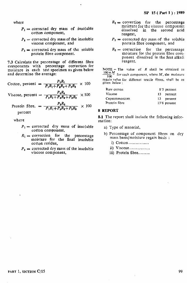
where
PI = corrected dry mass cotton component,
of :insoluble
Pa = corrected dry mass of the insoluble viscose component, and
PS = corrected dry mass of the soluble protein fibre component.
7.3 Calculate the percentage of different fibre components with percentage correction for moisture in each test snecimen as given below and determine the average:
Viscose, percent =
Protein fibre, - P&s PI&+P&+P&
percent
where
x 100
x 100
x 100
Pr = corrected dry mass of insoluble cotton component,
RI = correction for the percentage moisture for the final insoluble cotton residue,
P, - corrected dry mass of the insoluble viscose component,
SP 15 ( Part 1) : 1989
R 2 = correction for the percentage moisture for the viscose component dissolved in the second acid reagent,
PS = corrected dry mass of the soluble protein fibre component, and
R3 = correction for the percentage moisture for the protein fibre com- ponent dissolved in the first alkali reagent.
NOTE - The value of R shall be obtained as 100+M
~ for each component, where M, the moisture 100 regain value for different textile fibres, shall be as given below :
Raw cotton Viscose Cuprammonium Protein fibre
8 REPORT
8‘5 percent 13 percent 13 percent 13’6 percent
8.1 The report shall include the following infor- mation:
a) Type of material,
b) Percentage of component fibres on dry mass basis/moisture regain basis :
i) Cotton . . . . . . . . . . . . . . . . ii) Viscose . . . . . . . . . . . . . . . . iii) Protein fibre... . . . . . .
PART 1, SECTION c/15 99

As in the Original Standard, this Page is Intentionally Left Blank

SP 15 ( Part 1) : 1989
TERNARY MIXTURES OF PROTEIN FIBRES, NYLON 6 OR NYLON 6’6 AND CERTAIN OTHER FIBRES
( Source : IS 6503 : 1988 )
The use of different fibre blends in textiles has necessitated the formulation
analysis of textile fibres in mixtures is of consi-
methods for identification of standard derable importance to the textile technologists,
and quantitative traders and consumers. estimation of respective fibres. The quantitative
1 SCOPE
1.1 This standard prescribes two methods for the quantitative chemical analysis of ternary mixtures, after removal of non-fibrous matter, of natural or regenerated protein fibres and nylon 6 or nylon 6.6 and any of the following fibres:
a) Cotton or viscose rayon ( including poly- nosic fibre ),
b) Glass, or c) Polyester fibre.
NOTE - Before conducting an analysis according to this standard, the fibres present in the mixture should be identified and the sample to be analysed should be freed from all non-fibrous matter. Dye in the dyed fibres is considered to bs an integral part of the fibre and is not to be removed.
2 APPARATUS
2.1 Sintered Glass Filter Crucible
of appropriate capacity with .por e size of 90 to 150 microns ( porosity 1 ) and provided with a ground-glass stopper. If stopper is not available, the crucible should be enclosed in weighing bottle for weighing.
2.2 Desiccator
charged with self-indicating silica gel or anhy- drous calcium chloride.
2.3 Ventilated Oven
for drying samples at 105 f 3°C.
2.4 Analytical Balance
capable of weighing to an accuracy of O*OOO 2 g.
2.5 Conical Flask
of 100 ml capacity, provided with a ground- glass stopper.
2.6 Filter Flask
with connection to filter pump and adaptor to enable the crucible ( 2.1) to the fitted to it.
FART 1, SECTION c/ 16
2.7 Mechanical Shaker
3 REAGENTS
3.0 Quality of Reagents
Unless specified otherwise, pure chemicals shalL be employed in tests and distilled water shall be used where the use of water as a reagent is intended.
NOTE - ‘Pure chemicals’ shall mean chemicals that do not contain impurities which affect the test results.
3.1 Potassium or Sodium Hydroxide Solution
5 percent ( m/m ).
3.2 Acetic Acid
5 percent ( m/m ).
3.3 Formic Acid
80 percent (m/m) of sp gr 1,186 at 20°C. Dilute 880 ml of 90 percent (m/m) of formic acid ( sp gr l-204 ) to 1 litre with water. Alternatively, dilute 780 ml of 98 to 100 percent formic acid (m/m) ( sp gr 1.22 ) to 1 litre with water. The concentration is not critical within the range 77 to 8,3 percent (m/m ) ( sp gr 1.181 to l-191 ) formic acid.
3.4 Ammonia
80 ml of concentrated ammonia solution ( sp gr 0.89 ) diluted to 1 litre with water.
3.5 Hydrochloric Acid Solution
18 percent ( m/m ).
4 PREPARATION OF TEST SPECIMENS
4.1 From the sample, after removing size and finishes, draw a respresentative sample weighing about 2 to 3 g. Cut the yarn into pieces and dissect the cloth into yarn pieces of about 10 mm length.
101
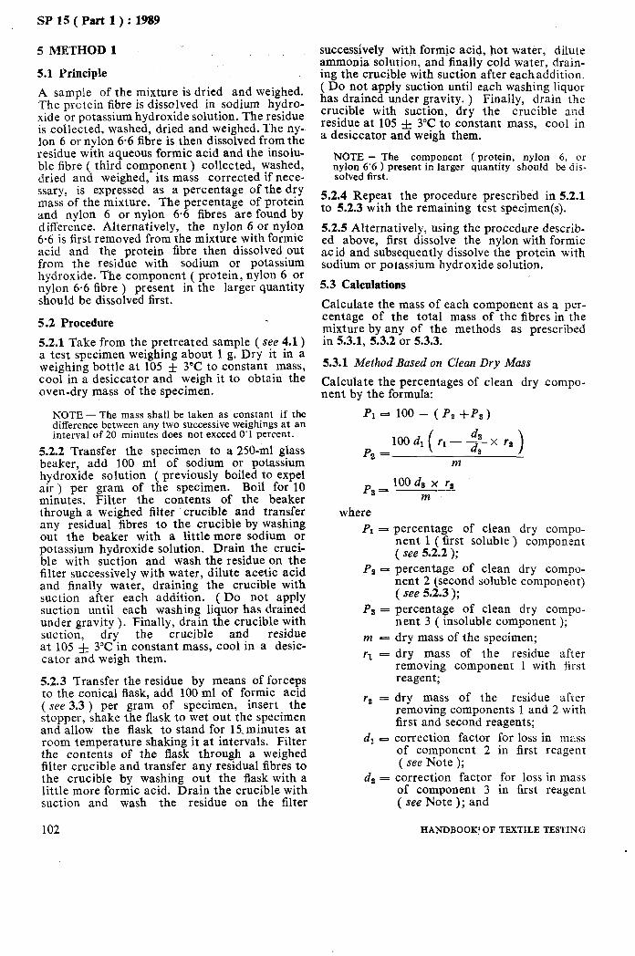
SP 15 ( Part 1) : 1989
5 METHOD 1
5.1 Principle
A sample of the mixture is dried and weighed. The prctein fibre is dissolved in sodium hydro- xide or potassium hydroxide solution. The residue is collected, washed, dried and weighed. The ny- lon 6 or nylon 6.6 fibre is then dissolved from the residue with aqueous formic acid and the insolu- ble fibre ( third component ) collected, washed, dried and weighed, its mass corrected if nece- ssary, is expressed as a percentage of the dry mass of the mixture. The percentage of protein and nylon 6 or nylon 6.6 fibres are found by difference. Alternatively, the nylon 6 or nylon 6.6 is first removed from the mixture with formic acid and the protein fibre then dissolved out from the residue with sodium or potassium hydroxide. The component ( protein, nylon 6 or nylon 6.6 fibre ) present in the larger quantity should be dissolved first.
5.2 Procedure
5.2.1 Take from the pretreated sample ( see 4.1) a test specimen weighing about 1 g. Dry it in a weighing bottle at 105 f 3°C to constant mass, cool in a desiccator and weigh it to obtain the oven-dry mass of the specimen.
NOTE - The mass shall be taken as constant if the difference between any two successive weighings at an interval of 20 minutes does not exceed 0’1 percent.
5.2.2 Transfer the specimen to a 250-ml glass beaker, add 100 ml of sodium or potassium hydroxide solution ( previously boiled to expel air ) per gram of the specimen. Boil for 10 minutes. Filter the contents of the beaker through a weighed filter crucible and transfer any residual fibres to the crucible by washing out the beaker with a little more sodium or potassium hydroxide solution. Drain the cruci- ble with suction and wash the residue on the filter successively with water, dilute acetic acid and finally water, draining the crucible with suction after each addition. ( Do not apply suction until each washing liquor has drained under gravity ). Finally, drain the crucible with suction, dry the crucible and residue at 105 & 3°C in constant mass, cool in a desic- cator and weigh them.
5.2.3 Transfer the residue by means of forceps to the conical flask, add 100 ml of formic acid (see 3.3 ) per gram of specimen, insert the stopper, shake the flask to wet out the specimen and allow the flask to stand for 15,minutes at room temperature shaking it at intervals. Filter the contents of the flask through a weighed filter crucible and transfer any residual fibres to the crucible by washing out the flask with a little more formic acid. Drain the crucible with suction and wash the residue on the filter
102
successively with formic acid, hot water, dilute ammonia solution, and finally cold water, drain- ing the crucible with suction after eachaddition. ( Do not apply suction until each washing liquor has drained under gravity. ) Finally, drain the crucible with suction, dry the crucible and residue at 105 f 3°C to constant mass, cool in a desiccator and weigh them.
NOTE - The component (protein, nylon 6, or nylon 6’6 ) present in larger quantity should be dis- solved first.
5.2.4 Repeat the procedure prescribed in 5.2.1 to 5.2.3 with the remaining test specimen(s).
5.2.5 Alternatively, using the procedure describ- ed above, first dissolve the nylon with formic acid and subsequently dissolve the protein with sodium or potassium hydroxide solution.
5.3 Calculations
Calculate the mass of each component as a per- centage of the total mass of the fibres in the mixture by any of the methods as prescribed in 5.3.1, 5.3.2 or 5.3.3.
5.3.1 Method Based on Clean Dry Mass
Calculate the percentages of clean dry compo- nent by the formula:
Pl - loo- (Pt+Ps)
Pz = 100 dl ( r1 - + x rl )
m
Ps - 100 d8 x rl
m
where PI = percentage of clean dry compo-
nent 1 ( first soluble ) component ( see 5.2.2 );
PB -
Ps =
m-
rl -
r, =
percentage of clean dry compo- nent 2 (second soluble component) ( see 5.2.3 ); percentage of clean dry compo- nent 3 ( insoluble component ); dry mass of the specimen; dry mass of the residue after removing component 1 with first reagent;
dry mass of the residue after removing components 1 and 2 with first and second reagents;
dl ~3 correction factor for loss in mass of component 2 in first reagent ( see Note );
dz = correction factor for loss in mass of component 3 in first reagent ( see Note ); and
HANDBOOK’ OF TtiXTILE TESTING
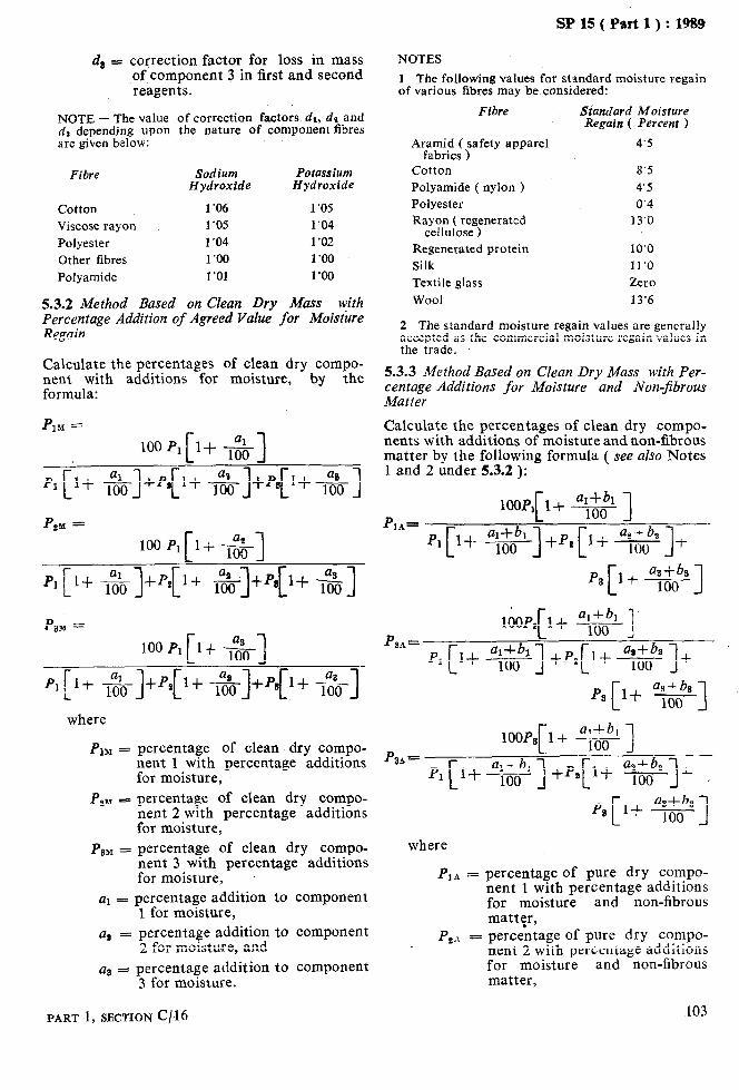
SP 15 ( Part 1) : 1989
d 3 = correction factor for loss in mass of component 3 in first and second reagents.
NOTE - The value of correction factors dl, dr and ds depending upon the nature of component fibres are given below:
Fibre Sodium Potassium Hydroxide Hydroxide
Cotton 1’06 1’0.5 Viscose rayon 1’05 1’04 Polyester 1’04 1’02 Other fibres 1’00 1’00
Polyamide 1’01 1’00
5.3.2 Method Based on Clean Dry Mass pith Percentage Addition of Agreed Value for Moisture Regain
Calculate the percentages of clean dry compo- nent with additions for moisture, by the formula:
P lrn =
100 PI [lf -&I
PI [1+ +]+P++ +]+Ps[l+ *]
P piv =
100 P,[l+ --&I
PI [ 1+ *]+PS[ I+ &]+Ps[l+ $1
PDM =
100 P*[l+ -g-j
PI [It &]+P,[1+ *]+qj+ -$O-]-
where
PlM =;
Pm =
Pm =
percentage of clean dry compo- nent 1 with percentage additions for moisture, percentage of clean dry compo- nent 2 with percentage additions for moisture, percentage of clean dry compo- nent 3 with percentage additions for moisture,
al = percentage addition to component 1 for moisture,
a2 = percentage addition to component 2 for moisture, and
as = percentage addition to component 3 for moisture.
NOTES
1 The following values for standard moisture regain of various fibres may be considered:
Fibre
Aramid ( safety apparel fabrics )
Cotton Polyamide ( nylon > Polyester Rayon ( regenerated
cellulose ) Regenerated protein Silk Textile glass Wool
Standard Moisture Regain ( Percent )
4’5
8’5 4’5 0’4
13‘0
10’0 11’0 Zero 13’6
2 The standard moisture regain values are generally accepted as the commercial moisture regain values in the trade.
5.3.3 Method Based on Clean Dry Mass with Per- centage Additions for Moisture and Non-fibrous Matter
Calculate the percentages of clean dry compo- nents with additions of moisture and non-fibrous matter by the following formula ( see also Notes 1 and 2 under 5.3.2 ):
loop, al+bl 1-t ___ P
100 1 IA=
[
p1 I$_ !.??.!I- 100 1 t -tPI + b* l++j- t 1
p3 I+ [
asfb3 I()()
3
aI+& 1
P 100 ~
IA= p1 l+ C
al+bl 100 I[ a,+& +p, 1+ I()() 1 +
P 3A’ r
Pl 1+ L
where
P ]A = percentage of pure dry compo- nent 1 with percentage additions for moisture and non-fibrous matttr,
p3 a&b3
1-t 100 I
1 + , p3 l+ [
as+& 100 1
P 2A = percentage of pure dry compo- nent 2 with percentage additions for moisture and non-fibrous matter,
103 PART 1, SECTION c/ 16
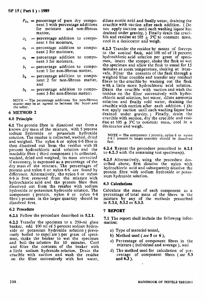
SP 15 ( Part 1) : 1989
P sA = percentage of pure dry compo- nent 3 with percentage additions for moisture and non-fibrous matter,
fll = percentage addition nent 1 for moisture,
a, = percentage addition nent 2 for moisture,
a3 - percentage addition nent 3 for moisture,
bt = percentage addition ^_
to compo-
to compo-
to compo-
to compo- nent 1 for non-fibrous .matter,
ba = percentage addition to compo- nent 2 for non-fibrous matter, and
bs - percentage addition to compo- nent 3 for non-fibrous matter.
NOTE - The percentage additions for non-fibrous matter may be as agreed to between the buyer and the seller.
6 METHOD 2
6.0 Principle
6.1 The protein fibre is dissolved out from a known dry ‘mass of the mixture, with 5 percent sodium hydroxide or potassium hydroxide solution. The residue is collected, washed, dried and weighed. The nylon 6 or nylon 6.6 fibre is then dissolved out from the residue with 18 percent hydrochloric acid solution and the insoluble fibre ( third component ) is collected, washed, dried and weighed; its mass corrected if necessary, is expressed as a percentage of the dry mass of the mixture. The percentages of protein and nylon 6 or nylon 6.6 are found by difference. Alternatively, the nylon 6 or nylon 6.6 is first removed from the mixture with hydrochloric acid and the protein fibre then dissolved out from the residue with sodium hydroxide or potassium hydroxide solution. The component ( protein, nylon 6 or nylon 6.6 fibre ) present in the larger quantity should be dissolved first.
6.2 Procedure
6.2.1 Follow the procedure described in 5.2.1.
6.2.2 Transfer the specimen to a 250-ml glass beaker, add 100 ml of 5 percent sodium hydro- xide or potassium hydroxide solution ( previ- ously boiled to expel air ) per gram of speci- men, shake the beaker to wet the specimen and boil the solution for 10 minutes. Cool and filter the contents of the beaker with a little sodium hydroxide solution. Drain the crucible with suction and wash the residue on the filter successiveiy with hot water,
dilute acetic acid and finally water, draining the crucible with suction after each addition. ( Do not apply suction until each washing liquor has drained under gravity, ) Finally drain the cruci- ble and residue at 105 f 3°C to constant mass, cool in a desiccator and weigh.
6.2.3 Transfer the residue by means of forceps to the conical flask, add 100 ml of 18 percent hydrochloric acid solution per gram of speci- men, insert the stopper, shake the flask to wet the specimen and allow the flask to stand for 15 minutes at room temperature, shaking at inter- vals, Filter the contents of the flask through a weighed filter crucible and transfer any residual fibres to the crucible by washing out the flask with a little more hydrochloric acid solution. Drain the crucible with suction and wash the residue on the filter successively with hydro- chloric acid solution, hot water, dilute ammonia solution and finally cold water, draining the crucible with suction after each addition. ( Do not apyly suction until each washing liquor has drained under gravity. j Finally, drain the crucible with suction, dry the crucible and resi- due at 105 f 3°C to constant mass, cool in a desiccator and weigh.
NOTE - The component ( protein, nylon 6 or nylon 6’6 ) present in larger quantity should be dissolved first.
6.2.4 Repeat the procedure prescribed in 6.2.1 to 6.2.3 with the remaining test specimen(s).
6.2.5 Alternatively, using the procedure des- cribed above, first dissolve the nylon with hydrochloric acid and subsequently dissolve the protein fibre with sodium hydroxide or potas- sium hydroxide solution.
6.3 Calculations
Calculate the mass of each component as a percentage of total mass of the fibres in the mixture by any of the methods prescribed in 5.3.1, 5.3.2 or 5.3.3.
7 REPORT
7.1 The report shall include the followrng infor- mation:
a) W Cl
d)
Type of material tested, Method used ( see 5 or 6 ), Percentage of component fibres in the mixture ( individual and average ), and The method used for calculation of per- centage of component fibres ( see 5.3 and 6.3 ).
I 104 HANDBOOK OF TEXTILB TESTING
SP 15 ( Part 1) : 1989
‘SECTION D
DETERMINATION OF PHYSICAL CHARACTERISTICS OF TEXTILE FIBRES

As in the Original Standard, this Page is Intentionally Left Blank

SP 15 (Part 1 ) : 1989
LINEAR DENSITY OF TEXTILE FIBRES ( GRAVIMETRIC METHOD )
( Source : IS 234 : 1973 )
The methods prescribed are in line with the IS0 1973-1976 ‘Determination of linear density
shed by International Organization for Stand- ardization.
of textile fibres - Gravimetric method’, publi-
1 SCOPE
1.1 This standard prescribes two methods for determination of linear density of textile fibres. One method is applicable to cut fibre bundles and the other to whole fibres.
1.1.1 Both the methods given are applicable only for discrete fibres ( excluding fibres like jute ) which can be kept straight and parallel during the preparation of bundles. They are not applicable to fibres having pronounced crimp ( such as wools ).
2 PRINCIPLE
2.1 Method I
A tuft having known number of fibres is cut in the middle to a known length and the mass of the cut middle portion is determined. From the mass and total length of fibres the linear density is calculated.
2.2 Method II
Fibres which have been sorted out previously into groups of known lengths are weighed and then counted. Then the mass per unit length is calculated from the number, mass and length of fibres.
3 PREPARATION OF TEST SAMPLE ’
3.1 The test sample from the gross sample shall be prepared as given in 3.2 and 3.3.
3.2 The gross sample of approximately 1 kg shall be spread out evenly on a level ground in the form of either a square with each side slightly greater than 1 m or in the case of a larger sample, a rectangle with the shorter side slightly greater than 1 m and the larger side slightly greater than 2 m. Over this, a metallic framework of size 1 m x 1 m with 25 sub-squares or 1 m x 2 m with 50 sub-squares, as the case may be, shall be placed. From each of these sub-squares one bunch ( or more ) of fibres shall be pulled out at random, taking care (a) not to exercise any bias in favour ofor against any particular place within a sub-square, and (b) that the fibres dravyn from each sub-square weigh about the same amount. The total I--
PART 1, SECTION D/l
quantity of about 5 to 10 g of fibres drawn shall constitute the reduced sample.
3.3 The reduced sample shall be divided into 25 or 50 approximately equal groups. From a different portion of each of these groups, one small tuft ( or more ) of fibres shall be extract- ed at random, taking care that the fibres drawn are nearly equal in weight, and the total weight of fibres thus drawn is not less than 200 mg. This shall constitute the ‘test sample’.
4 TESTING
4.1 After preconditioning, bring the sample to constant mass in the standard atmosphere. Carry out the test without removal from the standard atmosphere by Method I ( see 5 ) or Method II ( see 6 ). j
5 METHOD I - CUT BUNDLES
5.1 Apparatus
5.1.1 Balance
suitable for weighing the bundles of fibres to an accuracy of 0.02 mg and having 2 mg capa- city.
5.1.2 Device for Cutting the Fibres or Bundles of Fibres
to a known length with an accuracy of 1 per- cent and allowing of adjustment of the tension of the bundles to be cut.
NOTE - It is convenient to use two razor blades set parallel in a holder.
5.1.3 Velvet Board
of convenient size, covered with velvet of black or any other contrasting colour.
5.1.4 Glass Plate
of convenient size, with one polished edge.
5.1.5 Forceps
5.2 Procedure
5.2.1 From the final laboratory sample take 10 tufts of several milligrams and parallelize the fibres of each tuft by carefully combing them several times.
107

SP 15 ( Part 1 ) : 1989
5.2.2 Cut the middle part of each combed tuft to a given length ( as great as possible ) under the minimum tension necessary to remove crimp, by means of the cutting device. Take the necessary precautions so that there are no free fibre ends anywhere except at the two ends of the cut tufts.
5.2.3 Place the 10 tufts so obtained on the velvet board and cover them with the glass plate from the edge of which they should pro- trude slightly.
5.2.4 From each of the 10 tufts in turn, take out sufficient number of fibres, so as to form a tuft, weighing about 0.2 mg, in each case draw- ing the fibres from one cut end. Make sufficient number of tufts, so that a total number of at least 1 000 fibres in the case of natural fibres and 200 fibres in the case of man-made fibres are covered. Condition these tufts in the stand- ard atmosphere and then weigh them indivi- dually, using the balance to an accuracy of 0.02 mg.
5.3 Calculations
Calculate the linear density of the fibres by dividing mass by the total length of cut fibres in each tuft. Then determine the mean linear density for all the tufts from the values obtain- ed for each tuft.
6 METHOD II - WHOLE FIBRES
6.1 Apparatus
6.1.1 Microscope
with mechanical stage and magnification of at least 100 x.
6.1.2 Glass Slides
6.1.3 Cover Glasses
6..1.4 Twee ze rs
6.1.5 Balance
suitable for weighing bundles of fibres to an accuracy of 0.02 mg and having 2 mg capacity.
6.1.6 Mourzting Medium
water or mineral oil.
6.2 Procedure
6.2.1 From the final laboratory sample, prepare two complete fibre length arrays. Discard length groups less than 5 mm and those weighing less than 1 mg and treat these two sets as two sub- samples.
6.2.2 From each sub-sample prepare test speci- mens which shall consist, of a set of bundles of
108
approximately 100 fibres each taken by separat- ing them length-wise from each length group of‘ a sub-sample.
6.2.3 Take a bundle of fibre from a specimen (see 5.2.2) beginning with the longest group and weigh it to an accuracy of O-02 mg and record the mass. Then mount the fibres on the glass slides and cover them with the glass covers using some suitable mounting medium, if requi- red. Mark the slides for the length-group iden- tification.
6.2.4 Complete the preparation of the specimen by mounting the bundles from each length group.
6.2.5 Place each slide on the microscope stage turn by turn and count all the fibres in the slide. For reference see record sheet in Annex A showing a typical data of a cotton fibre specimen.
6.2.6 Similarly, prepare the slides and count the number of fibres on each slide for the second sub-sample also.
6.3 Calculations
6.3.1 Calculate the linear density of the fibres in the sub-sample as follows (see also Annex A):
Let
Ml = total mass of fibres in ith length group, in mg, to the nearest 0.2 mg;
ml - mass of counted fibres in ith length group, in mg, to the nearest 0.2 mg;
n1 =
11 =
.HI =
H=
Then
number of these fibres;
length of fibres in ith length group; linear density ( in mtex ) of fibres. in ith length group; and
linear density (in mtex) of all the fibres.
HI, mtex = 106 x 3 11
His given by the weighted harmonic means
H,mtex = f&J
HANDBOOK OF TEXTILE TBSTING
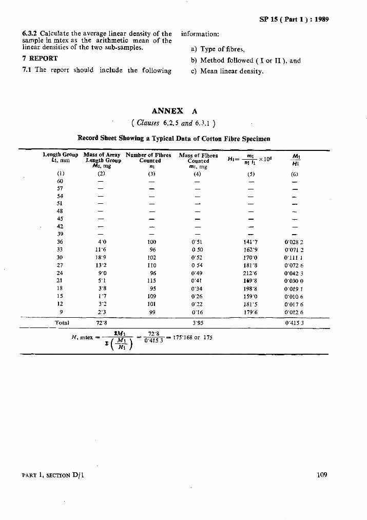
SP 15 ( Part 1) : 1989
6.3.2 Calculate the average linear density of the information: sample in mtex as the arithmetic mean of the linear densities of the two sub-samples. a) Type of fibres, 7 REPORT b) Method followed ( I or II ), and 7.1 The report should include the following c) Mean linear density.
ANNEX A
’ ( Chms 6.2.5 and 6.3.1 )
Record Sheet Showing a Typical Data of Cotton Fibre Specimen
(1) 60
57
54
51
48
45
42
39
36
33
30
27
24
21
18
15
12
9
Mass of Array Numb;;;itfibres Len&hzyp
(i,
- - -
- -
- -
4’0 100
11’6 96
18’9 102
13’2 110
9’0 96
5’1 115
3’8 95
1’7 109
3’2 101
2’3 99
Masp;o;Jjres
mi, mg
(4) -
-
-
-
-
-
-
-
0’51
0 50
0’52
0 54
0’49
0’41
0’34
0’26
0’22
0’16
Hi= fix106
(5) -
- - - - - -
141’7
162’9
170’0
181’8
212’6
169’8
198’8
159’0
181’5
179’6
Ml - Hi
(6) - - - - -
- -
0’028 2
0’071 2
0’111 1
0’072 6
0’042 3
0’030 0
0’019 1
0’010 6
0’017 6
0.012 6
Total 72’8 3’95 0’415 3
H, mtex = EM1 72’8
= -= 175’168 or 175 z
0’415 3
PART 1, SECTION D/ 1 109

As in the Original Standard, this Page is Intentionally Left Blank

SP lS(Part 1):1989
TENSILE CHARACTERISTICS OF INDIVIDUAL TEXTILE: FIBRES
(Source :IS 235:1988)
The tensile properties of individual fibres play an important role during manufacture, especially
applicable for natural fibres as well. However,
in case of man-made fibres, so as to make them this shall be more useful to technologists during
fit for specific end use. The method is also their research study.
1 SCOPE
1.1 This standard prescribes methods for deter- mination of tensile characteristics of individual textile fibres. The methods are applicable to all natural fibres and man-made fibres includ- ing crimped fibres provided that the available length of fibre enables a gauge length ( effective distance between mountings ) of 10 mm or 20 mm to be used.
1.1.1 The accuracy in the meaisurement of the elongation is better from increased test length. Hence, wherever possible, longer gauge length should be used.
1.2 Determination of these fibre properties, when carried out on different types of testing equipment, will not generally give identical results. To minimise the difference between results obtained on different types of testing equipment, this standard has been restricted to two types of testing equipment, namely:
a) equipment giving a constant rate of - extension of the fibre, and b) equipment giving a constant rate of load-
ing of the fibre.
1.2.1 Nevertheless, a difference up to 20 percent depending on the rate of application of force and elongation, can be expected betwe en results for a given fibre when tested by the two types of equipment. For this reason, it is recommended that the comparative tests should only be carried out on one type of ,testing equipment, which should be agreed to by the interested parties.
2 PREPARATION OF TEST SPECIMEN
2.1 Cotton and Other Natural Fibres
2.1.1 The test sample shall be cleaned and the fibres drawn between the forefinger and the thumb of one hand and those of the other. The fibres shall then be made into sliver which shall be drawn and doubled several times by hand.
2.1.2 A tuft of fibres taken from any end por- tion of the sliver shall constitute the test speci-
men for the purpose of mean individual fi bres strength and elongation.
2.1.3 The gross sample shall be spread out evenly on a level ground in the form of either a square with each side slightly greater than 1 m or in the case of larger sample, a rectangle with the shorter side slightly greater than 1 m and the longer side slightly greater than 2 m. Over this a metallic frame work of size ( 1 m x 1 m ) with 25 sub-square or ( 1 m x 2 m ) with 50 sub-squares as the case may be, shall be placed; from each of these sub-squares one bunch or more ,of fibres shall be pulled out at random taking care (a) not to exercise any bias in favour or against any particular place within a sub-square, and (b) that the fibres drawn from each sub-square weigh about the same amount ( about 4 g in the first case and about 2 g in the second case ). The total quantity of about 100 g thus drawn shall constitute the reduced sample.
2.1.4 The reduced sample shall be divided into 25 or 50 approximately equal groups. From different portions for each of these groups, small tufts or fibres shall be extracted at random, taking care that the fibres drawn are nearly equal in weight, and total weight of fibres thus drawn is not less than 200 mg. This shall constitute the test sample.
2.2 Man-Made Fibres
The procedure given in IS 4807 : 1968 shall be adopted.
3 APPARATUS AND REAGENTS
3.1 A tensile machine with suitable clamps for gripping the test specimen at a gauge length of 10 mm or 20 mm, means for stretching the fibre to rupture and a method of indicating the force applied to the test specimen and the corres- ponding elongation. The permissible error of the indicated breaking strength shall not exceed 1 percent of the mean breaking strength of the fibres and error of the indicated elongation at the breaking strength shall not exceed O-1 mm. The error of gauge length shall not exceed 0.2 mm. Tensile testing machine .of the type described in 3.1.2 and designed so as to avoid and jerk in the early. stages of application of force may also be used.
111 PART 1, SECTION D/2 . :
SPlS(Partl):l!W9
3.1.1 Constant Rate of Extension Machine
The machine shall be capable of applying a constant rate of extension to the fibre, such that after the first 2 seconds of the test, the rate of increase in the distance between the clamps does not differ by more than 5 percent from the average rate of increase over the whole period of test. The machine shall include facilities for producing different constant rates of extension in order to break the test specimen in an average time-to-break of 20 f 3 seconds.
3.1.2 Constant Rate of Loading Machine
The machine shall be capable of applying force at a constant rate such that after the first 5 seconds of the test, the average rate of increase of force in any 2 seconds interval does not differ by more than 25 percent from the average rate of increase of force over the whole period of test. The machine shall include facilities for applying force at different constant rates in order to break the test specimens in an average time-to-break of 20 f 3 seconds.
3.2 Clamps
These are’flat jaws for gripping the fibre speci- mens and designed to minimize slippage during the test.
3.3 Tabs
These are of thin plastic or other material for use with cementing techniques.
3.4 Means for enabling individual fibres to be placed without damage, between clamps of the instrument ( see Annex A ).
3.5 Cement or Adhesive
The adhesive should bind the tabs to the fibres without effecting an appreciable solution of the latter or any change in the moisture content of the specimen.
3.6 Distilled Water
at a temperature of 27 f 2”C, to which a non- ionic wetting agent has been added, to give concentration of about 0.1 percent.
3.7 Auxiliary Equipment
The testing machine may be equipped with auxiliary equipment to permit the automatic recording of data or the calculation of any required tensile property. The auxiliary equip- ment shall be capable of recording data and performing calculations in a manner consistent with the instructions for calculations as descri- bed in this method.
3.8 Jig
This is to aid in accurately mounting the test specimens on tabs ‘at the specified gauge length.
4 PROCEDURE
4.1 Condition the test specimen in the standard atmospheric conditions.
4.2 Set the machine to give the required dura- tion of test between the limits specified in 3.1.1 and 3.1.2.
4.3 Prepare and mount an individual fibre in the clamps of the testing machine ( see Annex A ). Ensure that the fibre lies along the axis of elongation of the machine. Start the tensile testing machine and associated auxiliary equip- ment, extending the fibre specimen to break.
4.3.1 Slack Mounting
Mount the fibres individually slightly slack, either directly between suitable clamps or on tabs.
4.3.2 Pre- tensioned Mounting
Mount the fibres individually between suitable jaws and apply a tension of 5.0 f 0.5 mN/tex for the dry test and 2.5 f 0.3 mN/tex for the wet test, calculated from the mean linear den- sity of the fibre.
NOTE - A higher pre-tension to remove crimp may be applied subject to the agreement between the con- cerned parties.
4.4 If the fibre specimen is mounted on tabs before being placed in the testing machine, the distance between tabs defines the nominal gauge length. The mounting of fibre specimens on tabs will be facilitated by use of an appro- priate jig.
4.4.1 When tabs are used, cut the tab across so that the iibre is free set the traversing jaw in motion and extend the test specimen to the point of rupture.
4.5 Unless, otherwise agreed by the interested parties test at least 50 specimens. Note jaw breaks, that is, breaks in which either of the broken ends is not visible and exclude the result obtained on such test specimens. The mean breaking load is the mean value of the breaking loads of all fibres taken. The mean elongation ( extension ) at break is the mean value of the elongation ( extension ) at break of , all test specimens. For determination of tena- city, the mean linear density of the test speci- men shall be calculated as prescribed for natural fibres and for man-made fibres.
112 HANDBOOK OF TEXTILE TESTING

SP 15 ( Part 1) : 1989
NOTE - As the coefficient of variation for the indi- vidual fibre tenacity is very high for natural fibres more number of tests of specimens are advisable for a desirable degree of accuracy. If the confidence limits for 50 tests do not differ by more than f 4 percent from the mean then this value is taken as the mean of the lot. Otherwise, the number of tests shall be increased until the confidence limits are brought within f 4 percent of the mean breaking load. ( For better significance of test results of the natural fibres at least 300 specimens may be taken and tested. 1
-4.6 Wet Specimens
Determine the properties of wet fibres on speci- mens immersed in a 0.1 percent aqueous solu- tion of a, non-ionic wetting agent. Allow sufficient wettingout time before testing to pro- duce the maximum change in breaking load and elongation at break as indicated by no further change with longer periods of immer- sion.
5 EXPRESSION OF RESULTS
5.1 Calculate the mean breaking strength of the fibres tested and express the result in mN.
5.2 Compute the mean tenacity of the fibres and express the result in mN/tex.
5.3. Calculate the mean elongation at break of the fibres and the mean elongation at break as
..a percentage of the gauge length (see Annex B).
5.4 Calculate the coefficient of variation ( CV ) of the breaking strength and of the elongation. at break.
5.5 In addition, if necessary, calculate any other required tensile properties for example, tenacity, modulus and breaking toughness etc ( see Annex C ).
6 TEST REPORT
6.1 The test report shall include the following:
4
‘4 C>
4
4 f 1 g)
Type of material tested;
Number of fibres tested;
Method followed: The method of mount- ing the fibres and the type of mounting, that is, pretensioned or on support tab;
Gauge length used;
Mean tenacity of the fibres in mN/tex;
Mean elongation at break, in percent;
Coefficient of variation of the breaking strength and elongation at break; and
h) Result of any other tensile properties required.
ANNEX A
( Clauses 3.4 and 4.3 )
MOUNTING OF TEST SPECIMEN
A-O It must be emphasized that great care should be taken to ensure that the fibre is not damaged, for example, the length of the fibre under test shall not be held with tweezers.
A-l Mount a test specimen in the jaws of the clamps, removing slack without stretching the specimen. The specimen shall be straight within the jaws and extreme care shall be taken to ensure that the fibre specimen lies on the line of action between the force-measuring device and the point where the fibre leaves the moving jaw face. Any misalignment that tends to pro- duce transverse motion of the clamps and jaws
will introduce errors in measurements of elon- gation and may contribute to premature fibre failure.
NOTES 1 For a slack mounted fibre, a tab may be used. A rectangular hole whose length is equal to the gauge length is cut in the tab and the fibre is mounted across the hole by means of a suitable adhesive. It is essential that the adhesive should not spread over the length of the fibre under test, both the tabs and the adhesive shall be waterproof.
2 For ore-tensioned fibres. suitable fibre clios shall be attached to the testing ‘machine. These can also be used for slack mounting if desired.
PART 1, SECTION D/2 113
SP 15 ( Part 1) : 1989
ANNEX B ( Clause 5.3 )
MEASUREMENT OF ELONGATION
R-l GENERAL R-2 SLACK MOUNTING
B-1.1 In measuring breaking elongation parti- cularly of crimped fibres, difficulty lies& decid-
B-2.1 From the force elongation curve, and
ing the starting point of test. taking into account of the gauge length used ( 10 mm or 20 mm ), determine the length be-
B-l.2 The initial portion of the curve is rarely tween the jaws of each test specimen, under a
linear, this part of the curve represents the pre-tension 5-O f 0.5 mN/tex or 2.5 f O-3 mN/ fibre bending in the grips, or the removal of the tex ( see 4.3.2 ). Use this length to calculate crimp, or a combination of these. the percentage elongation at break of the
fibre. B-l.3 For this reason, in particular where at the start of the force, elongation curve is very
B-3 PRE-TENSION MOUNTING
rounded, it may be useful to determine the ,B-3.1 The effective length of each test specimen theoretical start of elongation by extrapolation between the jaws being equal to the gauge to zero force from the straight portion of the length, the percentage elongation at break of force-elongation curve adjacent to the initial the fibre can be calculated directly from this portion of the curve. gauge length.
ANNEX C ( Clause 5.5 )
CALCULATIONS
C-I EFFECTIVE SPECIMEN LENGTH
C-1.1 Calculate the effective specimen length by drawing a line AB tangent to the initial slraight-line section of the load elongation curve and extrapolate it to intersect the zero load axis at I ( see Fig. 1 ). The correction ( or addition ) to specimen length in mm is given by the intercept OI. The effective specimen length ( mm) is the initial distance between the clamps ( the ‘nominal specimen length’ ) plus the correction ( or additional specimen length ) corresponding to 01.
C-l.2 When the load-elongation curve of a crimped specimen does not have an initial straight-line section below the yield point, draw a line tangent to the curve at the point of infle- ction below the yield point as an approximation of the initial modulus and report this fact.
C-2 ELONGATION AT BREAK
C-2.1 Mark a point E, on the zero load axis corresponding to the maximum load. Determine the elongation of the specimen in mm, corres- ponding to the length IE. Calculate the elonga- tion at break as a percentage of the corrected effective specimen length using the equation:
Elongation at break, percent = 100 x _X_
El@?
114
where IE = specimen elongation in mm, and Elm = calculated effective specimen I
length = Nominal specimen length + Additional specimen length ( OI)
C-3 MODULUS, INITIAL
C-3.1 Initial modulus is a measure of the resis- tance of the fibre to extension at loads below the yield point. For calculating initial modulus, calculate the tenacity in mN/tex corresponding to any convenient point P on the line AB by drawing a line PC perpendicular to the zero load axis. Calculate the fractional elongation ( Er ) corresponding to IC, that is, the ratio of IC to the effective specimen length. Then calcu- late the initial modulus as follows:
Modulus, Initial = Tenacity ( PCitex ) Ei
where PC = load indicated by distance PC in
Fig. 1, and El = fractional elongation correspond-
ing to distance IC.
C-4 MODULUS, SECANT
C-4.1 The secant modulus is also used to esti-- mate the resistance to imposed strain.
HANDBOOK OF TEXTILE TESTING-

Draw a line between any two specified points,for example, S and M on the load-elongation curve. Extrapolate the line to intersect the zero load axis at the point X. Drop a perpendicular from the point S to intersect the zero load axis at point R.
Modulus, Secant = Tenacity ( SR/tex)
Ef where
SR = load indicated by distance SR in Fig. 1.
El = fractional elongation correspond- ing to distance RX.
C-5 MODULUS, TANGENT
C-5.1 The tangent modulus may be used to differentiate between the probable performance of fibres in processing and end-use performance. Draw a line tangent to the load-elongation curve at the desired point on the curve which has been specified either in terms of the stress or the elongation at the point. Select the points on the tangent line and calculate the slope of the line as described in C-4.
C-6 BREAKING TOUGHNESS
.C-6.1 It is the energy per unit mass required to
FIG. 1A
SP 15 ( Part 1) : 1989
rupture the specimen. It is the integral of the nominal stress-strain curve and is calculated by dividing the work of rupture by the mass of the specimen under test.
Breaking toughness is calculated from the area under the load-elongation curve expressed as mN/tex ( mN. mm tex. mm ).
Breaking toughness = V/T
where
T = linear density, tex; and
V = work done in extending the fibre, mN ( mN. mm/mm), that is (AxSxR)/(GxWxL)
where
A = area under load elongation ( mm2 )
S = full-scale load ( mN )
R = crosshead speed ( mm/min )
G = effective specimen length ( correc- ted ) ( mm )
W = chart width ( mm ), and
L = chart speed ( mm/min ).
B ELONGATION (mm)
AB -TANGENT TO CU2VE 01
TYPICAL LOAD-ELONGATION CURVE OF INDIVIDUAL TEXTILE FIBRE
:PART 1,SECTION Dj2 115

As in the Original Standard, this Page is Intentionally Left Blank
SP 15 ( Part 1) : 1989
ESTIMATION OF MOISTURE IN COTTON
( Source : IS 199 : 1988 )
Moisture in cotton plays an important role in estimation is critical for estimation of mass in the quality characteristics. In order to have a cotton textile materials. repeatable and reproduceable results moisture
1 APPARATUS
1.1 Drying Oven
capable of maintaining a temperature of 105 f 3°C.
I.2 Weighing Balance
2 PROCEDURE
2.1 From the sample under test draw at least 2 test specimens each weighing approximately 3 g. 2.2 Take one test specimen drawn as in 2.1 and weigh it accurately in a clean and dry tared weighing bottle. Place the weighing bottle con- taining the test specimen in the drying oven and dry the specimen at 105 f 3°C to constant mass ( see Note ) and determine the oven-dry mass of the test specimen.
NOTE - The mass shall be regarded as constant if the loss between two successive weighings, taken at an interval of 20 minutes, does not exceed by 0’1 percent of the first of the two values.
2.3 Similarly test the other test specimen(s).
3 CALCULATIONS
3.1 Calculate the percentage of moisture content
in the test formula:
specimen
Moisture content, percent
where
by the following
= (a-b) --a- x 100
a = original mass in g of the test speci- men, and
b = oven-dry mass in g of the test specimen.
3.2 Determine the mean of all values, obtained in 3.1 and express it as moisture content of the material in the lot.
3.3 Corrected invoice mass of cotton textile materials may be calculated by the following formula:
L1= L ( b x 1.085) a
where
L1 = corrected invoice mass in g of the lot,
L = original mass in g of the lot, b = over-dry mass in g of the test
specimen, and a = original mass in g of the test speci-
men.
PART 1, SECTION D/3 117

As in the Original Standard, this Page is Intentionally Left Blank

sPlS(Pti1): 1989
.MICRONAIRE VALUE OF COTTON. FIBRIB. ._ 1
( Sour& : IS 3674 : 1966 j .’
Fineness in one of the important characteristics Much work on an international basis has been of cotton fibre. The airflow instruments, gene- done to develop and make available a range of rally prescribed for this method, operate on the cottons for the calibration of airflow instru- principle that the rate of airflow, through a plug of cotton fibre of fixed weight contained in
ments. By use of these calibration cottons and application of the procedures prescribed in this
a container of definite dimensions and subjected to a constant pressure head is related to the
test, it is possible to achieve agreement between two laboratories within h&2 micronaire units
fineness of the cotton fibr e. in the fineness measurement of the usual com- mercial sample of cotton.
1 SCOPE
1.1 This standard prescribes a method for the determination of micronaite value of loose dis- orientated cotton fibres by means of airflow ins- truments; this method is applicable to cotton taken from bales, laps, slivers or other sources of lint cotton.
2 PRINCIPLE
2.1 Air, under a specified pressure, is passed through a specimen of cotton of known weight confined to a space of known volume. The mass and volume of the specimen may be either cons- tant or varied in relation to each other accord- ing to the type of instrument used. The resistance of the specimen to the flow of air is related to the average fineness of the fibres in the specimen. The rate of flow of air through the specimen, or the pressure difference across the specimen ( according to the instrument used ), is indicated on a scale graduated in either arbitrary units of micronaire value or appropriate absolute units.
3 APPARATUS
3.1 Balance
The balance shall be of sufficient capacity to weigh the specimen required for the airflow instrument used, and capable of weighing the specimen to an accuracy of 10 mg.
3.2 Airflow Instrument
It shall consist of the following principal parts:
a) Compression cylinder with perforated ends for the admission and discharge of air. The cylinder may be either of a known fixed volume or of variable volume but adjustable to known volume and in either case, it shall have such dimensions that, with the prescribed weight of the specimen, each cubic centimetre of cylin- der shall contain between 0.16 to 0.30 g of cotton when compressed.
PART 1, SFETION D/4
‘4
Cl
4
One or more valves or other means for regulating and controlling the flow of air through, or the air pressure difference across the specimen.
A gauge or other means for measuring the resistance of the specimen to the airflow, or of the air pressure difference across the specimen. For example, a com- bination of a manometer for maintaining air pressure applied to the specimen and a flowmeter for indicating the rate of airflow through the specimen may be used.
An air pump or other means for produc- ing the required air pressure applied to the specimen, or the required pressure difference across the specimen.
4 ADJUSTMENTS AND CALIBRATION OF THE INSTRUMENT
4.1 Make preliminary adjustments appropriate to the instrument in use ( see Annexes B, C, D and E ).
4.2 Calibrate ( see Annex A ) the instrument by testing at least three specimens from at least three calibration cottons.
4.2.1 The instrument shall be considered to be in calibration, if it reads the calibration cottons within &to*1 micronaire value of the established values for the corresponding calibration cotton. If the instrument does not read within these limits, either (a) re-adjust the instruments and repeat the calibration procedure, or (b) use an appropriate correction factor based on the ratio established during the calibration of the instrument.
5 PREPARATION OF TEST SPECIMENS
5.1 Open the test sample with the fingers, break- ing up lumps if any and eliminating as much of the extraneous matter as possible. Condition the test sample.
119

SPl5(Partl):1983
5.2 Spread the opened, cleaned and conditioned test sample and divide it into 25 approximately equal groups. Extract small bunches of loose fibres from each group. Remove the pieces of non-fibrous material from fibres so collected and weigh at least two test specimens as in 5.3.
5.3 The test specimens shall be of the size pres- cribed for the instrument being used. In instru- ments having compression cylinders of fixed volume, the weight of the specimen shall be with- in kO.5 percent of specimen weigh appropriate for the instrument. In instruments having com- pression cylinders with adjustably varied volume, the weight of the test specimen used shall be known with an accuracy of f0.5 percent.
6 PROCEDURE
6.0 Make the necessary preliminary adjustments appropriate to the instrument used and carry out tests in standard atmosphere.
6.1 Place the test specimen in the fibre compre- ssion cylinder, a small portion at a time, taking care that all the fibres are placed inside.
6.2 Insert the compression plunger in position in the fibre compression cylinder and lock it.
6.3 Cause the air to flow through the specimen and read the airflow or the difference in pressure on the scale to an accuracy or half a division of the scale.
6.4 Remove the test specimen from the fibre compression cylinder. Open out the specimen and re-pack it into the fibre compression cylin- der, taking care that all the fibres are placed inside. Determine one more test value of the specimen in the manner prescribed in 6.2 and 6.3.
6.5 Take the other test specimen and determine the test values in the manner set out in 6.1 to 6.4.
NOTE - If the deviation of any individual reading is more than 0’2 from the mean value, prepare two more test specimens as prescribed in 5 and find out the test values by the procedure prescribed in 6.1 to 6.5.
7 CALCULATION AND EXPRESSION OF RESULTS
7.1 In instruments in which the scale is gradua- ted in micronaire units, find the average of the test values to the nearest O-1 micronaire unit and report it as the micronaire value of the cotton fibre in the lot.
7.2 For instruments in which the scale is gra- duated in units other than micronaire, convert the direct reading to micronaire units either from a previously prepared graph or by previ- ously fitted curve ( see A-3.1 ). Find the average of the values thus obtained to the nearest 0.1 micronaire unit and report it as the micronaire value of the cotton fibre in the lot.
NOTE - A conversion curve or a conversion equa- tion will have to be prepared for all instruments not having a micronaire scale in order to make full use of the calibration cottons referred to in Appendix A.
8 REPORT
The test report shal1 include the following:
a) The average value calculated as the micro- naire value of the lot;
b) The type, make and model of instrument used; and
c) The number of specimens tested.
ANNEX A
( czause 4.2 )
METHOD OF CALIBRATING AIRFLOW INSTRUMENTS
A-l CALIBRATION COTTONS
A-l.1 Secure calibration samples of the Inter- national Calibration Cottons series from the Cotton Division, Agricultural Marketing Service, United States Department of Agriculture, Washington 25, D.C., USA. These are furnished with micronaire values established by the Inter- national Calibration Cotton Standards Commi- ttee. Currently, there are nine such cottons. They approximately cover the range of micro- naire values of the world’s commercial cottons. Secondary calibration cotton series, correspond- ing to the International Calibration Cotton series, are proposed to be prepared in India.
120
A-2 CALIBRATION OF INSTRUMENTS WITH SCALE GRADUATED IN MICRONAIRE UNITS
A-2.1 For an airflow instrument equipped with a micronaire scale, use a minimum of two speci- mens from each of three of the calibration cottons when calibrating the instrument. Make two test determinations on each specimen, ihe second determination serving to check the first. The difference between the first and second readings on a test specimen shall not exceed 0.1 micronaire unit.
A-2.2 In instances where the difference between
HANDBOOK OF TEXTILB TESTING

the two readings exceeds 0.1 micronaire unit, prepare a new specimen of the calibration cotton and make two readings on it. Continue such readings until two specimens from calibration cotton have each been read within the tolerance specified.
A-2.3 Find the average of the first .readings of the three specimen and compare with the estab- lished value printed on the label of the calibration cotton. If none of the differences between the averages and the corresponding established values exceed O-10 micronaire unit, the instrument is considered to be in calibration. If greater differences occur make necessary adjustments in the instrument to bring it into compliance with established values of the cali-
SP 15 ( Part 1) : 1989
bration cottons. Alternatively, calculate a series of corrections to be applied to the readings of the cottons to be tested.
A-3 CALIBRATION OF INSTRUMENTS WITH SCALE GRADUATED IN OTHER THAN MICRONAIRE UNITS
A-3.1 For an airflow instrument equipped with scale graduated in other than micronaire units, establish the relation between the instrument readings and the established micronaire values for the calibration cottons by plotting a graph or fitting a curve. It is recommended to use as many calibration cottons as available preferably more than three.
ANNEX B
( Clause 4.1 )
OPERATION OF THE MICRONAIRE AIRFLOW INSTRUMENTS*
B-O GENERAL
B-0.1 There are several models of the micro- naire instrument which vary only in details of construction and operation intended to increase safety, ease and speed of operation. For any other operational or constructional details not given here, the manufacturer’s instructions supplied with the instrument shall be consulted.
B-l MICRONAIRE 60600 MODEL
B-l.1 Adjust and calibrate the instrument mechanically as follows. ’
B-1.1.1 Set the primary air regulator to a pres- sure of l-75 kg/cm* ( 25 lb/in’ ) and open the shutoff valve that admits air to the instrument.
B-1.1.2 Insert the manometer plug in the com- pression cylinder, allow the air to enter and adjust the secondary air regulator so as to obtain a pressure of 0.42 kg/cm% ( 6 lb/in* ) in compression cylinder. Again, if necessary, after the air flows through the instrument, re-adjust the regulating valve.
B-1.1.3 Insert one of the master orifice plugs, allow the air to enter, and if necessary, turn the calibration screw to bring the float to the posi- tion on the curvilinear scale corresponding to the designation of the orifice plug. Repeat these operations, using the other orifice plug or disc ( see Notes 1 and 2 ).
*Mention of the nanre of a specific ( or proprietory ) instrument is not intended to promote or give preference to the use of that instrument.
PART I, SECTION D/4
NOTES 1 Instead of two calibration discs, each with its bore, one disc with two different bores may be used. If the latter is used, close one of the bores with a finger at the lower scale value of 2’8, the bore to be closed being especially marked. 2 The scale readings 2’8 and 6’2 respectively corres- pond to flow rates of 21’1 Z!Z 0’8 litrelmin (0’75 & 0’03 ft’lmin I and 49’3 f 1’4 litre/min ( 1’74 & 0’05 ft’lmin ).
B-2 MICRONAIRE 80400 MODEL
B-2.1 Adjust and calibrate the instrument mechanically as follows. B-2.1.1 Operate the foot valve and see that the air pressure behind the filter is between 4.2 kg/ cm* ( 60 lb/ins ) and 8.8 kg/cm* ( 125 lb/ins ). B-2.1.2 Open the pressure regulator and the upper and lower adjusting valves, as far as possible. B-2.1.3 Insert the control disc in the test cham- ber, open the foot valve. Operate the pressure regulator so that the mercury column rises to O-31 kg/cm* ( 4.4 lb/i@ ), that is, to three scale units below the red line. The air shall pass through both bores of the control disc without hindrance.
NOTE - Operate the valve several times and see that the mercury always rises to the same height.
B-2.1.4 Adjust the upper edge of the float against micronaire value of 4-6 by regulating the lower adjusting valve. B-2.1.5 Adjust the upper edge of the float approximately to micronaire value of 6-O (upper check mark) by regulating the upper adjusting valve.
121

SF 15 ( Part 1 ) : 1989
B-2.1.6 Tightly close the upper opening of the NOTE - Open and close the upper opening of the control disc with one finger. The float will then control disc, several times. If the adjustments were
fall to about the level of lower check mark. correctly mad!, the float position shall correspond to t;;teyks wlthout further changes of the adjusting
B2.1.7 In order to make an exact adjustment, while alternatively opening and closing the upper opening of the control disc, alternately change the lower and upper adjusting valves. Do this until the upper edge of the float correspond with the two check marks located at about micronaire values of 2.9 and 6.0.
B-3 CALIBRATION AND TESTING
B-2.1.8 Turn the pressure regulator until the mercury column stands at 0.33 kg/cm* ( 4.7 lb/in* ).
B-3.1 After adjusting the instrument mechani- cally (B-1.1.1 to B-1.1.3 or B-2.1.1 to B-2.1.9, depending upon the instrument used ), check the instrument with at least three International Calibration Cottons ( see Annex A ). Repeat the check with the calibration cottons at frequent intervals.
B-2.1.9 By opening and closing tde upper open- ing of the control disc, check whether the upper and lower positions of the float still correspond with the two adjustment marks even after the change of the mercury column from 0.31 kg/cm* ( 4.4 lb/in2 ) to 0.33 kg/cm’ ( 4.7 lb/in2 ). If this does not occur, repeat the procedure as given in B-2.1.7.
B-3.2 After sampling, conditioning of samples and preparation of specimens the test specimen shall weigh 3.24 g f O-5 percent ( 50 grains f 0.5 percent ).
B-3.3 Follow the instructions given in 6.1 to 6.5 for loading the specimen, closing the compres- sion cylinder, and reading the gauge.
B-3.4 Follow the instructions given in 7.1 and 7.2 for calculating and reporting the test result.
ANNEX C
( Clause 4.1 )
OPERATION OF THE W.1.R.A FINENESS METER ( COTTON MODEL )*
C-O GENERAL manometer tube coincides with the upper ‘zero’ mark.
C-O.1 There are two models of the W.I.R.A. Fineness Meter ( Cotton Model ) described as the ‘old model’ and ‘new model’ respectively. They differ primarily in the scale units and size of test specimen used. The old model is gradua- ted in litres per minute and measures a speci- men weighing 6.0 g. The new model is equipped with a scale graduated in micronaire units and measures a specimen weighing 5-O g. For any other constructional or operational details not given here, the manufacturer’s instructions sup- plied with the instrument shall be consulted.
C-l ADJUSTMENT OF THE INSTRUMENT
NOTE - The lower edge of the meniscus is observed when noting the length of the liquid column.
C-2 CALIBRATION AND TESTING
C-2.1 After preliminary adjustment, calibrate the instrument by using at least three Inter- national Calibration Cottons ( see Annex A ).
C-2.2 After sampling, conditioning of samples. and preparation of specimens, the test specimen for the old model W.I.R.A. shall weigh 6.0 g -J-- 0.5 percent; and for the new model, it shall weigh 5.0 g & O-5 percent.
C-l.1 For preliminary calibration, adjust the instrument until the level of the liquid in the
C-2.3 Follow instructions given in 6.1 to 6.5 for loading the specimen, closing the compression cylinder, and reading the gauge.
*Mention of the name of a specific ( or proprietary ) instrument is not intended to promote or give preference C-2.4 Follow instructions given in 7.1 and 7.2 for to the use of that instrument. calculating and reporting results.
122 HANDBOOK OF TEXTILE TESTINCC
SPlS(Partl):1989
ANNEX D
( Clause 4.1 )
OPERATION OF THE ATIRA FIBRE FINENESS TESTER*
D-O GENERAL
D-O.1 The instrument developed by the Ahme- dabad Textile Industry’s Research Association ( ATIRA ) measures the ‘Micronaire value’ MC and ‘Maturity fineness’ MH of cottons on two separate scales. Cotton having MC values in the range of 2.5 to 6.5 or MH values from 1.5 to 7.0 may be tested on this instrument. MC value is the micronaire value and MH value is the pro- duct of the maturity ratio and the fineness in micrograms per inch as obtained by weighing whole fibres. For any other constructional or operational details not given here, the manufac- turer’s instructions supplied with the instrument shall be consulted.
D-l ADJUSTMENT OF THE INSTRUMENT
D-l.1 Level the instrument accurately with the levelling screws provided.
D-l..2 Check the level of the liquid in the mano- meter. The level shall coincide with the refe- rence mark on the initial vertical portion of the
*The ATIRA Fibre Fineness Tester is available at Ahmedabad Textile Industry’s Research Association, Navrangpura, Ahmadabad. Mention of the ,name of a specific ( or proprietary ) instrument is not intended to promote or give preference to the use of that instrument.
manometric scale. If the level is lower, open the reservoir and top up with the provided mano- metric liquid.
D-l.3 Squeeze the aspirator bulb, so that the float in the air tank rises to the top. As the float descends, gently close the flbre compres- sion cylinder with the rubber stopper. See that the level of the monometer liquid stays between the limits marked on the final vertical section of the scale.
D-2 CALIBRATION AND TESTING
D-2.1 After preliminary adjustment calibrate the instrument by usmg the International Cali- bration Cottons ( see Annex A ).
D-2.2 After sampling, conditioning of samples and preparation of specimens, the test specimen shall weigh 5.0 g f 0.5 percent.
D-2.3 Follow the instructions given in 6.1 to 6.5 for loading the specimen, closing the compres- sion cylinder and reading the gauge.
D-2.4 Follow the instructions given in 7.1 and 7.2 for calculating and reporting the test result.
ANNEX E
( Clause 4.1 )
OPERATION OF PORTAR FIBRE FINENESS TESTER*
E-O GENERAL
E-Q.1 It is a portable Arealometer meant for use at places where the cotton is traded or process- ed. It is graduated in ‘equivalent fibre thickness’ in microns and micronaire units. The two scales are graduated from 3 to 7 microns and 2.5 to 7 micronaire units respectively. It measures a specimen of 8-O g. It can be read to an accuracy of &0*05 micronaire unit. For any other cons- tructional or operational details, not given here, the manufacturer’s instructions supplied with the instrument shall be consulted.
*Mention of the name of a specific ( or proprietary ) * instrument is not intended to promote or give preference
to the use of that instrument.
PART 1, SECTION D/4
El ADJUSTMENT OF THE INSTRUMENT
El.1 Place the instrument on a level surface and remove the cover. Check the zero of the permeability indicating meter.
E-l.2 Place a weight, of 8 g on the weighing scale and with the compression lever in the top posi- tion, adjust the zero screw until the permeabi- lity indicating meter reads near the red mark on the scale.
E-l.3 Take approximately 8.0 g of cotton and place on the weighing scale. Give one stroke to the pump of the atomizer bulb and see whether the specimen is heavier or lighter than 8.0 g. If the indicator goes above the red mark, the
123
,
SP 15 ( Part 1 ) : 1989
specimen is heavier and if it goes below, the E-2.2 After sampling, conditioning of samples specimen is lighter. By taking off or adding bit and preparation of specimens the test specimen by bit, adjust the specimen weight to 8.0 g. shall weigh 8-O + 0.5 percent.
E-2.3 Follow the instructions given in 6.1 to 6.5
E-2 CALIBRATION AND TESTING for loading the specimen, closing the compres- sion cylinder and reading the gauge.
E-2.1 After preliminary adjustment calibrate the instrument by using the International Cali-
E-2.4 Follow the instructions given in 7.1
bration Cottons ( see Annex A ). and 7.2 for calculating and reporting the test result.
124 HANDBOOK Oi- TEXTILE TES’l-ING-
SF 15 ( Part 1) : 1989
COTTONFIBREMATURITY (SODIUM HYDROXIDE SWELLING ~~ETI~oD)
( Source : IS 236 : 1968 )
It prescribes three methods for determination of cotton fibre maturity, keeping in view the
may be followed for routine testing in view of
practices prevalent in the industry. The results its simplicity. The terminology used in the
obtained by all the three methods are highly three methods ( I, II and III ) is different from method to method and has been defined in each
correlated and any one of them ca n beused for case. The definitions of one method should not the determination of maturity of cotton fibres. be confused with those of the other method. However, it is recommended that Method II
1 SCOPE
1.1 This standard prescribes the following three methods for determination of cotton fil~;ho~turity by sodium hydroxide swelling
Method I Coefficient of maturity ( C, ) Method II Percentage of mature fibres (PM) Method III Maturity ratio ( M)
2 APPARATUS
2.1 A microscope fitted with a mechanical traversing stage and having a magnification power of 200x, 400 x to 500 x , and 150 x for methods I, II and III respectively.
2.2 Glass slides and cover slips.
2.3 Scissors, forceps, glass rod, etc.
2.4 Sodium hydroxide solution, 18 percent.
2.5 Draw box.
3 PREPARATION OF TEST SPECIMENS
3.1 If the test sample is in the form of a sliver, lay it on a velvet-covered board, and if the test sample is in the form of .a rovin g or yarn, untwist several strands before laying them parallel to each other side by side on the velvet-covered board. Place a glass plate over the test sample with its long edge at right angle to the length of the test sample. With the help of sharp scissors, cut the test sample as near to the edge of the glass plate as possible. With the help of forceps, remove and discard the fibres whose cut ends are projecting right up to the edge of the glass plate.
3.1.1 Move the glass plate backwards ( about 1 mm ) and with the help of forceps, remove and discard the fibres by gripping the protrudmg ends, right up to the edge of the glass plate. Move the glass plate backwards again and similarly remove and discard the protrudmg fibres.
3.1.2 Move the glass plate backwards a third time and then remove the fibres with the help
of forceps and lay them on a glass slide in such a manner that the fibres are approximately parallel to one another. Place about 100 fibres on each slide over a length of about 20 mm. Cover the fibres with cover slip and irrigate the fibres with 18 percent sodium hydroxide solution. Prevent the formation of air bubbles by tapping the cover slip lightly while irrigat- ing the fibres. Remove the excess solution at the edges with absorbent tissue or blotting paper. :
3.1.3 Similarly prepare four more slides.
4 METHODS
4.1 Method I ( Coeffieieat .of Maturity CM )
4.1.1 Terminology
a) Fibre mazurity count - The fibre maturity count is denoted by the percentages of the mature, half mature and immature fibres in a sample.
b) Maturity - The degree of fibre wall deve- lopment .
4.1.2 Principle
The fibres are classified into mature, half mature and immature fibres on the basis of the ratio of their lumen width to their wall thick- ness, both values being determined after the fibres have been swollen fully in 18 percent sodium hydroxide solution, as given below:
Value of Lumen Width
Wall Thickness Class
Between 0 and 1
Between 1 and 2
Above 2
4.1.3 Procedure
Mature
Half mature
Immature
4.1.3.1 Adjust the microscope condenser to give critical illumination and then move it slightly to obtain a uniformly-lit field of veiw. Place the first mounted slide as prepared in 3.1.2 ( after about 5 minutes of its irrigation
PART .~,SJK%ION D/5 ’ 125
SP15(Partl):m9
with sodium hydroxide solution ) on the micro- stop.: stage in such a manner that the central portions of the fibres are beneath the objective. Examine the fibres one by one by moving the stage in the transverse direction.
4.1.3.2 Estimate the ratio of lumen width to wall thickness of each fibre and classify it into mature, half mature and immature fibre ( see 4.1.2 ). Classify the fibres on the basis of appearance of the portion in the field of view and do not move the slide in the lateral direc- tion during testing. In the case of twisted fibres, this estimation shall be made at the widest part of the fibre seen in the field of view between successive twists. Test the four other slides in the similar manner.
4.1.4 Calculation
Calculate the percentages of mature, half mature and immature fibres from the total number of observations made by combining the counts of all the five slides. Express the three percentages as maturity count of the cotton.
The coefficient of maturity ( Caa ) shall be cal- culated by the following formula:
c&l== m + 0.6 h + O-4 i
100 where
m - percentage of mature fibres, h = percentage of half mature fibres,
and i = percentage of immature fibres.
4.2 Method II ( Percentage of Mature Fibres PM ) 4.2.1 Terminology
4
b)
cl
4.2.2
Maturity - The degree of fibre wall deve- lopment. MatureJibres - Fibres that after being treated with strong caustic solution swell into an untionvoluted and almost rod-like shape where total wall width is equal to or greater than the lumen width. Immature Jibres - Fibres that after being treated with strong caustic solution either: (1) swell and assume a spiral form; or (2) remain flat, thinly outlined and almost transparent. In any case, the total wall width is less than the lumen width.
Principle’
The fibres are swollen in 18 percent sodium- hydroxide solution and then classified into two groups, mature and immature. The percentage of mature fibres is calculated from the total number of observations.
4.2.3 Procedure
4.2.3.1 Adjust the microscope condenser to givt critical illumination and then move it slightly to obtain a uniformly-lit field of view. Place the first mounted slide as prepared in 3.1.2 ( after about 5 minutes of its irrigation with sodium hydroxide solution ) on the microscope stage in such a manner that the central por- tions of the fibres are beneath the objective.
4.2.3.2 Examine the fibres one by one by mov- ing the slide in the transverse direction and classify them into mature and immature fibres ( see 4.1.2 ). Classify the fibres on the basis of the appearance of the portion in the field of view and do not move the slide in the lateral direction during testing. Test the four other slides in a similar manner.
4.2.4 Calculation
Calculate the percentage of mature fibres from the total number of observations of all the five slides by the following formula:
Percentage of mature fibres ( PM ) = -y- x 100
where m = total number of mature fibres, and t = total number of observations.
4.3 Method III ( Maturity Ratio M)
4.3.1 Terminology
a) Degree of wall thickening - The ratio of
b)
C>
d)
e)
f)
actual c%oss-sectional a’rea of the wall to the area of the circle with the same perimeter. Maturity ratio - The ratio of actual degree of wall thickening to a standard degree of thickening equal to 0.577. NormalJibre - Fibres which after swell- ing appear rod-like with no continuous lumen. Swollen normal fibres have no well-defined convolutions. Deadjbres - Fibres in which after swell- ing the wall thickness is one-fifth or less than the maximum fibre width. Swollen dead fibres vary from flat forms, with no convolutions and little or no secondary fibre wall to highly-convoluted forms with greater wall development. Thin walledjbres - Fibres which do not fall into either the normal or dead fibre groups. Maturity - The degree of fibre wall development.
4.3.2 Principle
The fibres are swollen in 18 percent sodium- hydroxide solution and classified into normal,
126 HANDBOOK OF TEXTiLB TESTING
dead and thin walled fibres. The percentages combined in to of the three classes of fibres are
a single index termed maturity approximately proportional to wall thickening.
ratio which is the degree of
4.3.3 Procedure
4.3.3.1 Adjust the microscope give critical illumination and slightly to give a uniformly-lit
.
condenser to then move it field of view.
Place the first mounted slide as prepared in 3.1.2 ( after about 5 minutes of its irrigation with sodium-hydroxide solution ) in the micro- scope stage in such a manner that the central portions of the fibres are beneath the objective.
4.3.3.2 Move the slide in the transverse direc- tion and count the total number of fibres. Again move the slide and count the number of normal and dead fibres ( see 4.3.1 ). Classify the fibres on the basis of the appearance of the portion in the field of view and do not move the slide in the lateral direction during testing. The observations of libre width and wall thick- ness shall be taken at the widest portion in the field of view. Test four other slides in the simi- lar manner.
SP 15 ( Part 1 ) : 1989
4.3.4 Calculation
Calculate the percentage of normal and dead fibres after combining the observations of all the five slides. Calculate the maturity ratio from the difference between the percentages of normal and dead fibres by using the following formula:
M= L (N-D) + 200
0.70 1 where
M = maturity ratio, N = percentage of normal fibres, and D = percentage of dead fibres.
5 REPORT
5.1 The report shall include the following infor- mation:
a> b) C>
4
Type of material tested ( sliver, roving or yarn, etc ); Number of fibres tested; Method followed ( Method I, II or III ); and Coefficient of maturity ( CM ) or percen- tage of mature fibres ( PM ) or maturity ratio (M), as the case may be.
PART 1, SECTION D/5 127

As in the Original Standard, this Page is Intentionally Left Blank

SP 15 ( Part 1 ) : 1989
COTTON FIBRE IMMATURITY COUNT - POLARIZED-LIGHT METHOD
( Source : IS
It prescribes a polarized-light method for esti- mating the percentage of immature fibres in a sample of cotton. This method is intended to be an alternative to sodium hydroxide swelling method as far as the determination of percent- age of immature fibres in a sample of cotton is concerned. In the sodium hydroxide swelling method, fibres are classified as (a) mature fibres, (b) half-mature fibres, and (c) immature fibres on the basis of the ratio of the width of their lumen to the width of their wall, both being
1611 : 1960 )
determined after the fibres have swollen in 18 percent caustic soda solution. But, in the pola- rized-light method prescribed in this standard, fibres are classified as (a) immature fibres, and (b) non-immature fibres, on the basis of the colour observed under polarized light. For the same sample of cotton, the percentage of imma- ture fibres determined by polarized-light method may differ slightly from the corresponding value determined by caustic soda swelling method.
1 SCOPE
1.1 This standard prescribes a method for determination of percentage of immature fibres in the samples of cotton using polarizing micro- scope.
2 APPARATUS
2.1 ,Microscope, with a magnification of 100 x to 200x and provided with a rotating stage graduated in degrees, shall be used. The micro- scope shall be equipped with a polarizer and an analyzer, a first order red selenite plate and a cross-hair eyepiece mounted so that the hairs make an angle of 45” with the plane of polarization.
3 PROCEDURE
3.1 From the test sample take a tuft of about 80 to 100 fibres and place it on a slide so that the length of the fibres lies along the length of the slide. Arrange the fibres on the slide parallel to one another with as little overlapping as possible and cover the slide with a wide cover- slip or another slide ( see Note ).
NOTE - The fibres may be mounted on the slide with water or liquid paraffin; in such a case, care should be taken to see that there is no air bubble between the fibres.
3.2 Prepare four more slides in the manner prescribed in 3.1.
3.3 Check the microscope to make sure that the analyzer and polarizer are set at extinction ( crossed ), with the selenite plate removed. Insert the selenite plate with the slow-vibration direction ( as indicated by the arrow on the selenite plate ) at 45 degrees to the polarization plane of the polarizer. Set the eyepiece so that one of the cross-hairs is parallel to the arrow of the selenite plate.
PART 1, SECTION D/6
3.4 Make certain that the microscope stage is properly centred.
3.5 Place the prepared slide ( see 3.1) on the mechanical stage of the microscope so that the fibres lie parallel to the 45” cross-hair of the eyepiece ( that is, the fibres are then in the additive position of the selenite and are parallel with the slow-vibration direction of the selenite, as indicated by the arrow on the selenite ).
3.6 Move the fibres across the stage parallel to the cross-hair. As each fibre comes into view, observe its colour. If the predominant colour at the widest portion of the fibre is purple or blue, record it as an immature fibre; if it is of any other colour, record it as a non-immature fibre.
3.7 Similarly, examine the remaining 4 slides and note down the number of immature and non-immature fibres.
4 CALCULATIONS
4.1 Calculate the percentage of immature fibres in the slide by the following formula:
Immature fibres, percent Total number of immature fibres
a Total number of fibres examined x loo
4.2 Determine the mean of the five values and report it as percentage of immature fibres.
4.3 Find the mean of the five values and report it as the immature fibres, percent.
5 REPORT
5.1 The report shall include the following infor- mation:
a) Type of material; and b) Immature fibres, percent.
129

As in the Original Standard, this Page is Intentionally Left Blank

SP 15 ( Part 1) : 1989
LINT AND TRASH CONTENT OF COTTON BY MEANS OF MECHANICAL-PNEUMATIC MACHINES
( Source : IS 4871 : 1968 )
The deiermination of lint and trash content of raw cotton is important since the presence of trash directly influences the net amount of yarn or cloth that can be manufactured from a given lot of cotton.
The amount of trash remaining in vsirious inter- mediate products like scutcher lap, card sliver, etc, indicates the cleaning efficiency of the
processes or machines. Also the amount of use- ful lint present in the waste removed at various machines helps in making the adjustment and settings of various cleaning points of the machines. Thus, the analysis of intermediate products and wastes for lint and trash contents helps in profitable adjustment and operation of the machines to clean the cotton to a predeter- mined degree.
1 SCOPE
1.1 This standard prescribes a method for determination of lint and trash content of cotton fibres by means of mechanical-pneumatic machines. The method is applicable to cotton taken from bales, laps, slivers or other sources of lint cotton.
1.1.1 The method may also be used for analys- ing the waste removed by different machines for the lint and trash content.
2 PRINCIPLE
2.1 A known weight of the specimen is fed to the machine. The specimen is well opened by the machine and then discharged in an air stream. The ,air stream carries the fibres to the surface of a condenser cage and allows the heavier par- ticles of trash to fall down. The lint and the waste are collected in separate compartments. The amount of lint and trash so collected are separately weighed and computed as the per- centages of the original weight of the specimen.
3 APPARATUS
3.1 Balance
a balance of sufficient capacity and capable of weighing to an accuracy of 10 mg.
3.2 Analyser
a machine working on mechanical-pneumatic principle capable of separating trash and lint fractions. The machine shall be equipped with accessories given in 3.2.1 to 3.2.3.
3.2.1 Containers
for holding the specimen and different fractions thereof.
3.2.2 Brushes
for assisting in the collection of fractions from various compartments.
PART 1,SECTION D/7
3.2.3 Gauges and Tools
for making adjustments and settings of the machine.
NOTE - One commercially available analyser namely Shirley analyser is described in Appendix A.
4 PREPARATION OF TEST SPECIMENS
4.1 From the sample(s), draw test specimens in such a way that these are representative of the sample(s), but at the same time keep the number of pieces making up the specimen to a mini- mum consistent with the representative samp- ling.
NOTE - While preparing the samples from the lot and specimens from the samples, take care that no trash is lost in handling.
4.2 The test specimen shall be of the size in conformity with what is specified in the opera- ting instructions for the instrument being used. A small deviation from the exact prescribed size is justified, if it helps in preventing shedding of trash during drawing and weighing. Weigh the specimen to an accuracy of 100 mg (M).
4.3 Test at least 2 test specimens.
5 PROCEDURE
5.0 Make the necessary preliminary adjustments in accordance with the instructions given in Annex A or with the manufacturers’ instruc- tions. 5.1 Shake the specimen so that large particles of trash (which may otherwise damage the machine ) are removed from the specimen; pre- serve these droppings for incorporation in the trash in 5.6. Spread the specimen on the feed plate between the guide plates in the form of an even layer after opefling out the hard lumps, if any ( for details see Annex A ).
5.2 Start the machine and let the trash and lint collect in their respective compartments ( for details see Annex A ).
131
SP 15 ( Part 1) : 1989
5.3 Take out the lint from the delivery box and pass it again through the machine without dis- turbing the trash in the settling chamber. Stop the machine and collect the lint and keep it in a separate container ( L1 ).
5.4 Remove all the trash particles containing lint from the trash tray and settling chamber and pass it through the machine. Collect the lint from the delivery box.
5.5 Pass the lint collected as in 5.4 through the machine without disturbing the trash. Collect the lint and keep it in a separate container (L,) .
5.6 Collect all the trash in the trash tray, settling chamber and any seeds clinging to the wires of the taker-in cylinder and combine them. Weigh them to an accuracy of 100 mg and if the weight is less than 10 g, weigh to an accuracy of 10 mg ( T1 ).
5.7 Pass the particles containing lint again through the machine and ignore the trash collecLed. Collect the lint and keep it in a separate container and weigh to an accuracy of 10 mg (LB).
5.8 Combine all the portions of the lint ( LI, LI and L3 ) as cpllected in 5.3, 5.5 and 5.7 and weigh to an accuracy of 10 mg.
NOTE- A schematic representation of the procedure is given below:
6 CALCULATION
6.1 Calculate the results as lint content, trash content ( visible waste content ), and invisible waste content as percentages of the original specimen by the following formulae:
a) Lint content (L), in percent
= L1 + L-2 + L3 x 1(-J)
m
b) Trash content ( visible waste ) ( T ), in percent
= (T1- L3) )( I()()
A4
c) Invisible waste content ( W ), in percent - 100 - (L + T)
where L1, L,and & = mass of the lint portion in
grams as in 5.3,5.5 and 5.7 respectively;
Tr - total mass of trash portion in grams; and
M = mass of the specimen in grams.
NOTE - The calculation of invisible waste content may be omitted if agreed between the concerned‘ parties. In such a case, obviously, the combined mass. of trash and lint would be less than the original weight of the sample.
7 REPORT
7.1 The test report shall include the following:
a)
‘9 4 d)
e)
Type of material tested ( whether raw cotton, sliver, lap or waste from some. machine ); Number and mass of specimens tested; Name of the machine used; Atmospheric conditions under which the test is conducted; and The percentage of the following or any of them as agreed to between the con- cerned parties:
1) Lint content, 2) Trash content, and 3) Invisible waste content.
132 HANDBOOK OF TEXTILE TESTING

SP 15 ( Part 1 ) : 1989
ANNEX A ( Clauses 3.2.3, 5.0, 5.1 and 5.2 )
DESCRIPTION AND OPERATION OF SHIRLEY ANALYSER
A-l The Shirley analyser separates lint and trash by making use of the difference of their buoyancies in the air. The specimen is fed to the taker-in cylinder with the help of feed roller and feed plate arrangement. The fibres are opened by the taker-in cylinder and are carried by an air stream and deposited on a cage similar to a condensing screen. The air stream is so adjusted that it carries only the cotton fibres and dust, leaving the trash to fall in the lower portion of the machine. The dust passes through the cage to the exhaust and the fibres are collected in the delivery box.
A-2 Before using the machine, the delivery box, trash tray, settling chamber, etc, should be swept clean. If the machine has not already been used during the day, start the motor and run the machine for 2 or 3 minutes for warming up, keeping the clutch disengaged and the feed roller in-operative.
A-3 Spread the specimen uniformly to cover the whole area between the guides on the feed plate, teasing out hard lumps where necessary. When making tests on slivers, short lengths should be spread on the feed plate perpendi- cular to the feed roller. Open the valve to its fullest extent, engage the clutch and observe the character of the trash as it begins to fall into the tray. Only small amounts of unopened lint should be falling with the trash in this first passage and, for hard cotton, it may occasion- ally be necessary to tighten the loading springs on the feed rollers. When all the specimen has passed under the feed roller, asindicated by the absence of fibres under the streamer plate, disengage the clutch and close the valve momentarily to allow the lint to be collected from the delivery box.
A-4 The mass of the specimen shall normally be 100 g.
A-5 Sveeds and settings of the Shirley analyser shall be as follows: -
Speeds qf
Taker-in cylinder Feed roller Cage Fan Motor
Setting Between
Feed plate and taker- in
Streamer plate ( lead-in edge ) and taker-in
Streamer plate (lead-off edge ) and taker-in
Stripping knife ( bottom edge ) and taker-in
Stripping knife ( bottom edge ) and cage
Taker-in and cage
Separation sheet ( top edge ) and cage
Delivery plate and cage
NOTES
mm 0.1
0.15
o-2
o-1
8.0
5-o to 6.0
6-O
1.5
rev/min
900 0.9
80 1 500 1 400 approx
(4,ZOO)
(5/l 000)
(7/l 000)
(4/l 000)
(5/16)
(13/64 to E/64)
(l/4)
(l/16)
1 Specially designed feed plate for staples above 32 mm is available, the use of which minimizes fibre breakage on long-staple cotton. It is used when fur- ther tests are to be made on the lint portion but the results of the analyser are not affected by its use. For the purpose of this test, the usual plate having a flat striking face of 28’6 mm shall be used.
2 The filter bags shall be kept clean to avoid back pressure.
PART I, SECTION D/7 133

As in the Original Standard, this Page is Intentionally Left Blank

SP 15 ( Part 1 ) : 1989
LENGTH PARAMETERS OF COTTON FIBRES
( Source : IS 233 : 1978 )
The fi.bre length of cotton is directly related to its spinn’lng performance; generally speaking, longer cartons can be spun to finer counts. The method of estimating fibre length or ‘staple’ of cotton used in the trade has long been accepted to be liable to considerable subjective and per- sonal errors, and the need for accurate methods of determining the mean fibre length of cotton and the proportion by weight of fibres of diffe- rent length grades in cotton has long been recogniz,ed.
The methods given are intended for the estima- tion of different length, parameters like mean length, effective length, upper quartile length, half-fall length, span length, percent short fibres,
coefficient of variation of length, and uniformity index of a sample of cotton fibres, raw as well as processed.
The length parameters measured by different instruments differ from one another, and no interrelationship can be given with sufficient accuracy. However, experimental data broadly show that a cotton of 32 mm effective length by the Comb Sorter may give 27 to 28 mm effec- tive length by the Uster Staple Diagram Appa- ratus, and 27 mm 2.5 percent span length by the Digital Fibrograph. The mean fibre length may be about 25 mm by the Comb Sorter, while the Uster instrument may give a value of 21 mm.
PART 1, SECTION D/8 135

As in the Original Standard, this Page is Intentionally Left Blank

ESTIMATION
1 SCOPE
SP 15 ( Part 1 ) : 1989
OF LENGTH AND LENGTH DISTRlBUTION BY THE ARRAY METHOD
[ Source : IS 233 ( Part 2 ) : 1978 ]
1.1 This standard prescribes a method for esti- mation of mean fibre length, effective length, percent short fibres and coefficient of variation of length by array method.
2 PRINCIPLE
2.1 A sample of fibres is arranged in the form of an array in the descending order of length, and from a tracing of this array the effective length, mean length, percent short fibre and coefficient of variation of length are calculated.
3 APPARATUS
3.1 Two Comb Sorters
to prepare the fibre array, each comprising a bed of combs, an upper and a lower set - each spaced about 5 mm apart.
3.2 AC cessories
as given below:
a> b) cl 4 e)
.
Fibre grip, Teasing needle, Rake to press in the fibres, Velvet pad, and Rectangular perspex scale (160 x 80 mm) marked in 5 mm squares.
4 PROCEDURE
4.1 Preparation of Aligned Tuft from the Test Sample (Using Two Comb Sorters )
4.1.1 Place one sorter in a suitable position such that the first of the bottom combs which can be dropped in succession, faces the opera- tor. Lift the upper combs, and lay the represen- tative sliver towards the right and across the lower bed of combs; about 20 to 30 mm of the sliver should project beyond the nearest comb. Press the sliver into the combs with the rake. Remove the projecting fibres with the grip, and square the sliver to obtain alignment with the first comb.
4.1.2 Place the second sorter conveniently by the side of the first, but with the last of the bottom combs towards the operator. Lift the upper combs.
4.1.3 Drop the first bottom comb of the first sorter, so that about 5 mm of the squared end of the sliver projects out. Using the fibre grip, remove these fibres in short draws of full width,
and place the tufts so drawn towards the left and across the bottom combs of the second sorter, such that the aligned ends of the tufts lie along the row of needles of the last bottom comb ( nearest the operator ). The fibres should be laid straight and at right angles to the comb rows. Press each tuft down into the combs with the rake. Drop the second bottom comb of the first sorter, and continue to transfer and pile up tufts on the second sorter until about 25 mg( or sufficient quantity of fibres to prepare on array of about 100 to 150 mm length ) is built up.
4.1.4 Lower the upper combs.
4.2 Prepatation of the Fibre Array
4.2.1 Turn the sorter round through 180 degrees.
4.2.2 Drop sufficient number of lower combs and raise upper combs, wherever necessary, until the longest fibres project about 5 mm.
4.2.3 Using the grip, pull out small tufts of successively shorter lengths. Comb and straigh- ten fibres in each tuft, and lay them side by side on the velvet pad such that the free ends of the tufts lie along a straight base line. A continuous array of uniform density is produced by skilfully using the teasing needle and a forefinger to arrange each tuft perpendicular to the base line and joining up with the previous one. Successive top and bottom combs are moved as shorter and shorter fibres are pulled out and joined into the pattern. The last few tufts should be very carefully arranged so that no short fibres are lost. It should also be ensured that the pattern is of uniform density throughout as the ultimate evaluation is based on this assumption.
4.2.4 Trace the outline of the fibre array pre- pared on a sheet of translucent paper ( see Fig. 1 ).
5 CALCULATION AND EXPRESSlON OF RESULTS
5.1 Calculate the following length from the comb sorter diagram ( Fig.
1
parameters 1 )*
FIG. 1 COMB SORTERDIAGRAM
PART 1, SECTION D/8-1 137
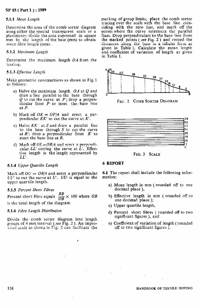
SP 15 ( Part 1 ) : 1989
5.1.1 Mean Length
Determine the area of the comb sorter diagram using either the special transparent scale or a planimeter; divide the area mm by the length of the
expressed in square base (mm) to obtain
mean fibre length (mm-!.
5.1.2 _kfaximunt Length
Determine the maximum tracing.
51.3 Effective Length
length OA from the
Make geometric constructions as shown in Fig. 1 as follows:
4
b)
C)
4
Halve the maximum length OA at Q and draw a line parallel to the base through Q to cut the curve at P’; drop a perpen- dicular from P to meet the: base line at P.
Mark off OK = OP/4 and erect a per- pendicular KK’ to cut the curve at K’.
Halve KK’ at Sand draw a parallel line to the base through S to cut the curve at R’; drop a perpendicular from R’ to meet the base line at R.
Mark off OL=OR/4 and erect a perpendi- cular LL’ cutting the curve at L’. .Effec- tive length is the length represented by LL’.
5.1.4 Upper Quartile Length
Mark off OU = OB/4 and erect a perpendicular Uu’ to cut the curve at U’. UUf is equal to the upper quartile length.
5.1.5 Percent Short Fibres
Percent short fibre equals $ x 100 where OB
is the total length of the diagram.
5.1.6 Fibre Length Distribution
Divide the comb sorter diagram into length groups of 4 mm interval (see Fig. 2). An impro- ;ised scale as shown in Fig. 3 can facilitate the
marking of group limits; place the comb sorter tracing over the scale with the base line coin- ciding with the zero line, and mark off the points where the curve intersects the parallel lines. Drop perpendicularsto the base line from the marked points ( see Fig. 2 ) and record the distances along the base in a tabular form as given in Table 1. Calculate the mean length and coefficient of variation of length as given in Table 1.
FIG. 2 COMB SORTERDIAGRAM
pzz!! FIG.~ SCALE
6 REPORT
6.1 The report shall include the following infor- mation: .
a)
b)
4 4’
Mean length in mm ( rounded off to one decimal place ),
Effective length in mm ( rounded off to one decimal place ); Upper quartile length,
Percent short fibres ( rounded off to two significant figures ), and
e) Coefficient of variation of length (rounded off to two significant figures ).
138 HANDBOOK OFTEXTILE TESTING

.
SP 15 ( Part 1 ) : 1989
Table 1 Length Frequency Data from Comb Sorter Diagram
(Clause 5.1.6 )
Lower Group Limit
(1) (2) (3) mm mm mm 48 50 1 44 46 6 40 42 29 36 38 58 32 34 82 28 30 103 24 ’ 26 11s 20 22 127 16 IS 135 12 14 144
8 10 158 4 6 171 0 2 179
Group
LeYh
Distance Along Base
Relative Group
Freqzncy3
(4)
Percentage Group
Frequency, fl
(5)
1 5
23 29 24 21 15 9
-
9 14 13
8
0’6 30’0 1 500’0 2’8 128’8 5 924’8
12’8 537’6 22 579’2 16’2 615’6 23 392’8 13’4 455’6 15 490’4 11’7 351’0 10 530’0 8’4 218’4 5 qs.4 5’0 110’0 2 420’0 4’5 81’0 1 458’0 5’0 70’0 980’0 7’8 78’0 780’0 7’3 43’8 262’8 4’5 9’0 18’0
fi Ii
(‘3 (7)
fi ii2
179 100’0 2 728’8 91 014’4 Zfi’ Xfi Zfi ri Zfi Ii’
Zf ill 2 728’8 Mean length = _ =- = 27’3 mm Cfi 100
Xfl 1is - ( Efi Ii Y
Variance = - =fi =fi
= 91 014’4 - 74 463’5 = 165.5 100
Standard deviation ( 0) = l/variance = j//165.5 = 12’9
Coefficient of variation ( CV) = & X 100 = * X 100 = 47’2
length
PART 1, SECTION D/8-1 139

As in the Original Standard, this Page is Intentionally Left Blank
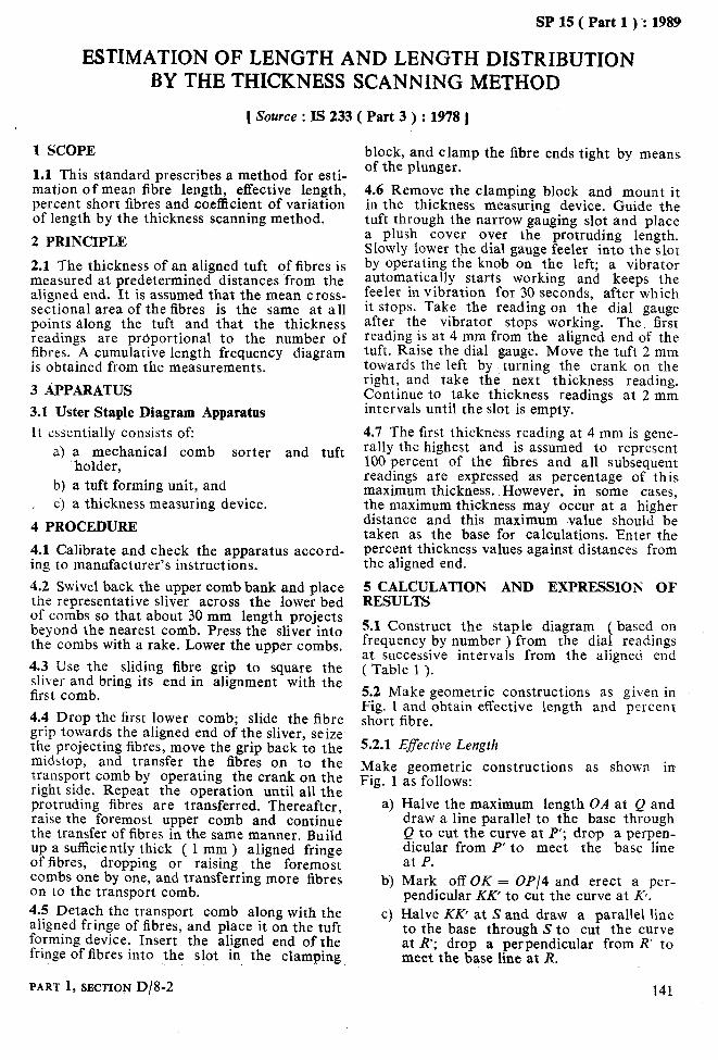
SP 15 ( Part 1 ) -: 1989
ESTIMATION OF LENGTH AND LENGTH DISTRIBUTION BY THE THICKNESS SCANNING METHOD
[ Source : IS 233 ( Part 3 ) : 1978 )
1 SCOPE
1.1 This standard prescribes a method for esti- mation of mean fibre length, effective length, percent short fibres and coefficient of variation of length by the thickness scanning method.
2 PRINCIPLE
2.1 The thickness of an aligned tuft of fibres is measured at predetermined distances from the aligned end. It is assumed that the mean cross- sectional area of the fibres is the same at all points along the tuft and that the thickness readings are proportional to the number of fibres. A cumulative length frequency diagram is obtained from the measurements.
3 APPARATUS
3.1 Uster Staple Diagram Apparatus
It essentially consists of: a) a mechanical comb sorter and tuft
‘holder,
b) a tuft forming unit, and , c) a thickness measuring device.
4 PROCEDURE
4.1 Calibrate and check the apparatus accord- ing to manufacturer’s instructions. 4.2 Swivel back the upper comb bank and place the representative sliver across the lower bed of combs so that about 30 mm length projects beyond the nearest comb. Press the sliver into the combs with a rake. Lower the upper combs. 4.3 Use the sliding fibre grip to square the sliver and bring its end in alignment with the first comb.
4.4 Drop the first lower comb; slide the fibre grip towards the aligned end of the sliver, seize the projecting fibres, move the grip back to the midstop, and transfer the fibres on to the transport comb by operating the crank on the right side. Repeat the operation until all the protruding fibres are transferred. Thereafter, raise the foremost upper comb and continue the transfer of fibres in the same manner. Build up a sufficiently thick ( 1 mm ) aligned fringe of fibres, dropping or raising the foremost combs one by one, and transferring more fibres on to the transport comb. 4.5 Detach the transport comb along with the aligned fringe of fibres, and place it on the tuft forming device. Insert the aligned end of the fringe of fibres into the slot in the clamping,
PART 1, SECTION D/8-2
block, and clamp the fibre ends tight by means of the plunger.
4.6 Remove the clamping block and mount it in the thickness measuring device. Guide the tuft through the narrow gauging slot and place a plush cover over the protruding length. Slowly lower the dial gauge feeler into the slot by operating the knob on the left; a vibrator automatically starts working and keeps the feeler in vibration for 30 seconds, after which it stops. Take the reading on the dial gauge after the vibrator stops working. The. first reading is at 4 mm from the aligned end of the tuft. Raise the dial gauge. Move the tuft 2 mm towards the left by turning the crank on the right, and take the next thickness reading. Continue to take thickness readings at 2 mm intervals until the slot is empty.
4.7 The first thickness reading at 4 mm is gene- rally the highest and is assumed to represent 100 percent of the fibres and all subsequent readings are expressed as percentage of this maximum thickness. However, in some cases, the maximum thickness may occur at a higher distance and this maximum -value should be taken as the base for calculations. Enter the percent thickness values against distances from the aligned end.
5 CALCULATION AND EXPRESSION OF RESULTS
5.1 Construct the staple diagram ( based on frequency by number ) from the dial readings at successive intervals from the aligned end ( Table 1 ). 5.2 Make geometric constructions as given in Fig. 1 and obtain effective length and percent short fibre.
5.2.1 Effective Length
Make geometric constructions as shown in Fig. 1 as follows:
a) Halve the maximum length OA at 0 and draw a line parallel to the base thyough Q to cut the curve at P’; drop a perpen- dicular from P’ to meet the base line at P.
b>
C)
Mark off OK = OP/4 and erect a per- pendicular KK’ to cut the curve at fi. Halve KK’ at S and draw a parallel line to the base through S to cut the curve at R’; drop a perpendicular from R’ to meet the base line at R.
141

SP 15 ( Part 1) ‘: 1989 .
d) Mark off OL=OR/4 and-erect a perpendi- cular LL’ cutting the- curve at L’. Effec-
5.3 Work out fibre length distribution, mean length and coe%sient of- variation of fibre
tive length is the length represented by length from the data as shown in Table 1, or LL’. from the staple diagram as detailed in 5.1.6 in
Section D/8-1. 5.2.2 Percent Short Fibres
RB 6 REP& Percent short fibre equals -oB x 100 where OB
is the total length of the diagram. 6.1 Report shall include the following infor- mation:
1; 0 KL U B
FIG. 1 COMB SORTER DIAGRAM
a) Mean fibre length in mm ( rounded off to one decimal place ),
b) Effective length in mm ( rounded off to one decimal place ),
c) Percent short fibres ( rounded off to two significant figures ), and
d) Coefficient of variation of length ( roun- ded off to two significant figures ).
Table 1 Length-Frequency Data from Tests with Uster Staple Diagram Apparatus ( Clauses 5.1 and 5.3 )
Group Length ( Distance from Aligned End 1, li
(11 mm
40
38
36
:r
32
30
28
26
24
22
20
18
16
14
12
10
8
6
4
Dial Reading
(2)
0 0
4 0’3
10 0’8
32 2’5
82 6’4
116 12’9
286 22’2
410 31’8
542 42’1
668 51’8
188 61’1
890 69’0
980 76’0
1 050 81’4
1 102 85’5
1 150 89’0
1 204 93’3
1 234 95’6
1 290 100
Cumulative Prewn;~ >
(3)
Percent Group
Freqzucy
(4)
0 0 0
0’3 11’4 433’2
0’5 18’0 648’0
1’7 57’8 1 965’2
3’9 124’8 3 993’6
6’5 195’0 5 850’0
9’3 260’4 7 291’2
9’6 249’6 6 489’6
10’3 247’2 5 932’8
9’7 213’4 4 694’8
9’3 186’0 3 720’0
7’9 142’2 2 559’6
7’0 112’0 1 792’0 5’4 75’6 1 055.4
4’1 49’2 590’4
3’5 35’0 350’0
3’3 26’4 211’2
2’3 13’8 82’8
4’4 17’6 70’4
fi Ii
(5) (6)
fi 112
100’0 2 035’4 47 733’2
Efi Zfi Ii Zfl 1P
2 035’4 Mean length ( lm ) = $!! = boo- = 20’4 mm
Variance -
Cfi I? - ( Zfifi )” Zfl
B.K_ *
47 733’2-44428’5 _ 63,047 100
Standard deviation ( U) = {Variance = 463’041 = 7’94
Coefficient of variation ( CP > ‘: 7’94
+&,x 100 = - 20’35
x 100 = 39 percent
142 HANDBOOK OF TEXTILB TBSTING

SP 15 ( Part 1 ) : 1989
ESTIMATION OF LENGTH AND LENGTH UNIFORMITY BY THE OPTICAL SCANNING METHOD
[ Source : IS 233 ( Part 4 ) : 1978 1
1 SCOPE
1.1 This standard prescribes a method for esti- mation of 2.5 percent span length, 50 percent span length and uniformity index of cotton fibres by optical scanning method.
2 PRINCIPLE
2.1 A randomly aligned tuft of cotton fibres is scanned by an optical device and the minimum length spanned by certain specified percentages of the fibres is determined. The ratio of lengths spanned at two percentages is considered as a measure of fibre length uniformity.
3 APPARATUS 3.1 Digital Fibrograph
It is an optical instrument which scans a randomly aligned tuft of fibres to estimate the length of specific portions of the length frequ- ency distribution, like 2.5 percent span length, 50 percent span length.
3.2 A Set of Hand Combs or a Fibro-Sampler
for preparation of tufts.
4 PROCEDURE
4.1 Preparation of Test Specimen
Prepare the test specimens from the laboratory sample by one of the following methods given in 4.1.1 or 4.1.2.
4.1.1 Hand Combing Method
Pick up a handful of cotton from the labora- tory sample and separate it into two parts by pulling so as to expose a fresh surface of pro- jecting fibres. Holding one of the hand combs in one hand and the opened lump of cotton in the other, transfer some of .the proj ecting fibres on to the comb. Pick fresh lumps of cotton, and proceed in the same manner so that a pair of combs is filled with sufficient quantity of fibres drawn from 8 to 10 randomly picked lumps. Hold one comb in each hand, and untangle and parallelize the projecting fibres by mutual combing. The pair of combed beards constitutes the test specimen.
4.1.2 Fibro-Sampler Method
Mount one of the fibro-sample combs in the comb holder of the Fibro sampler, with the
teeth uppermost. Place the laboratory sample in the cage and press it against the perforated surface. Maintain the pressure and rotate the sample holder round the drum counter- clockwise through 360”. Remove the loaded comb from the holder. Turn the sample in the cage to expose a fresh surface, and mount fibres in one more comb. Either one or a pair of combed beards constitute the test specimen depending upon the model of the instrument being used.
4.2 Optical Scanning of Test Specimens
4.2.1 Assure that the fibrograph is in proper operating condition; check calibration accord- ing to instruction manual.
4.2.2 Insert the loaded pair of combs into the comb holder, and brush the fibres downward carefully to remove loose fibres and straighten the rest.
NOTE - In some fibrograph models a single comb constitutes the test specimen.
4.2.3 Lower the light house; wait for the signal to indicate ‘balance’. See that the amount counter reading is within specified limits. If the quantity of fibres is too much or too less, reject the test specimens and prepare fresh ones.
4.2.4 Follow the procedure laid down for res- pective models and record the 50 percent and 2.5 percent span length values.
5 CALCULATION AND EXPRESSION OF RESULTS
5.1 Express 2.5 percent span length and 50 per- cent span-length correct to 0.1 mm. Calculate the uniformity index as follows:
6 REPORT
6.1 The report shall include the following. infor mation:
a) 50 percent span length, b) 2.5 percent span length, and c) Uniformity index ( rounded off to two
significant figures ).
PART 1, SECTION D/8-3 143

As in the Original Standard, this Page is Intentionally Left Blank
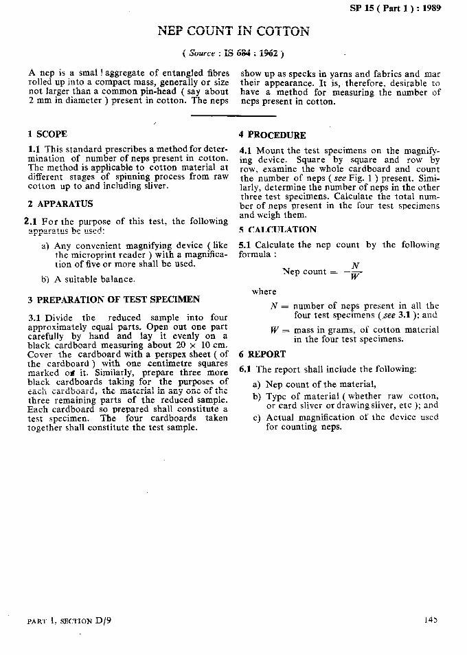
lu-_____
SP 15 ( Part 1) : 1989
NEPCOUNTINCOTTON
( Source : IS 684 : 1962 )
A nep is a small aggregate of entangled fibres rolled up into a compact mass, generally or size
show up as specks in yarns and fabrics and mar
not larger than a common pin-head ( say about their appearance. It is, therefore, desirable to
2 mm in diameter ) present in cotton. The neps have a method for measuring the number of neps present in cotton.
1 SCOPE
I
1.1 This standard prescribes a method for deter- mination of number of neps present in cotton. The method is applicable to cotton material at different stages of spinning process from raw cotton up to and including sliver.
2 APPARATUS
2.1 For the purpose of this test, the following apparatus be used:
a) Any convenient magnifying device ( like the microprint reader ) with a magnifica- tion of five or more shall be used.
b) A suitable balance.
3 PREPARATION OF TEST SPECIMEN
3.1 Divide the reduced sample into four approximately equal parts. Open out one part carefully by hand and lay it evenly on a black cardboard measuring about 20 x 10 cm. Cover the cardboard with a perspex sheet ( of the cardboard j with one centimetre squares marked od it. Similarly, prepare three more black cardboards taking for the purposes of each cardboard, the material in any one of the three remaining parts of the reduced sample. Each cardboard so prepared shall constitute a test specimen. The four cardboards taken together shall constitute the test sample.
4 PROCEDURE
4.1 Mount the test specimens on the magnify- ing device. Square by square and row by row, examine the whole cardboard and count the number of neps ( see Fig. 1 ) present. Simi- larly, determine the number of neps in the other three test specimens. Calculate the total num- ber of neps present in the four test specimens and weigh them.
5 CALCULATION
5.lCa~late the nep count by the following
Nep count = $
where
N=
w=
6 REPORT
number of neps present in all the four test specimens (see 3.1 ); and
mass in grams, of cotton material in the four test specimens.
6.1 The report shall include the following:
a) b)
C)
Nep count of the material, Type of material ( whether raw cotton, or card sliver or drawing sliver, etc ); and Actual magnification of the device used for counting neps.
PART 1, SECTION D/9 145

As in the Original Standard, this Page is Intentionally Left Blank

SP 15 ( Part 1 ) : 1989
PART 1, SECTION D/9
FIG.~ FULL SIZEPHOTOGRAPH ILLUSTRATING THBNEPS
149

As in the Original Standard, this Page is Intentionally Left Blank

SP 15 ( Part 1 ) : 1989
BUNDLE STRENGTH ( TENACITY ) OF COTTON FIBRES
( Source : IS 3675 : 1966 )
Strength of cotton fibre contributes substan- tially to the quality of cotton. The method of estimating the tenacity of cotton by testing individual fibres is tedious and time consuming. For both commercial and technical purposes, quicker methods have been developed which test the fibres in the form of bundles. This covers some such methods.
The bundles of fibres may be secured by clamps which are either in close contact ( zero gauge length ) or by clamps separated to give a finite
gauge length. Fibre strength testing at zero gauge length is a current commercial practice, although investigations indicate that tests at a finite gauge length of 3.175 mm ( or l/8 in) may be more closely related to the tenacity of many classes of cotton yarn.
International Calibration Cotton Standards have been established to enable different opera- tors to adjust their personal level of testing to an agreed common level.
1 SCOPE
1.1 This standard prescribes a method for deter- mination of strength of flat bundles of cotton fibres arranged in parallel manner; the method is applicable to fibres being tested either at zero gauge length or at 3.175 mm ( or l/8 in ) gauge length.
1.2 The method is applicable to fibres from raw cotton or to fibres from various stages in the manufacturing process or to fibres separated or extracted from manufactured cotton products.
1.3 This method is especially intended to be used with strength testing instruments which have been designed for specific use of testing flat bundles of cotton fibres (see Annexes A and B ).
2 PRINCIPLE
2.1 A flat bundle is fastened in a pair of clamps of prescribed size and the fibres protruding beyond the clamps are cut. Increasing force is applied to the specimen until it ruptures. The broken fibres are weighed and the ratio of the breaking load to the weight of fibres is deter- mined and the tenacity is calculated therefrom. The test may be carried out either at zero or at 3.175 mm ( or l/8 in ) gauge length.
3 APPARATUS
3.1 Balance
capable of weighing to an accuracy of f 0.01 mg.
NOTE - A balance of capacity 0 to 5 mg is sufficient for most fibre bundle strength tests. If test specimens are to be weighed collectively ( see Note 1 under 7.1.2 >, use a balance of capacity 0 to 10 mg or 0 to 20 mg capable of weighing to an accuracy of ~tO.02 mg.
3.2 Fibre Bundle Strength Tester
Two commercially available fibre bundle
PART 1, SECTION D/10
strength testers are described in Annexes A and B. Other strength testers may be used, if equipped with adapters to accommodate the fibre clamps of Pressley type. The strength tes- ter shall be equipped with the following accessories.
3.2.1 Specimen Clamps ( of Pressley Type )
A pair of clamps with a combined width of 11.81 mm ( 0.465 in ), while testing at finite gauge length, a suitable spacer, usually of 3.175 mm ( or l/8 in ) may be used between the clamps.
3.2.2 Clamp Vice
A jig equipped with a locking screw or cam for holding the clamps while,they are being loaded and unloaded. A vice equipped with an appro- priate construction to ensure the application of predetermined force when tightening the jaws of the clamps, may be preferred.
3.2.3 Devices
For preparation of specimens and removing them from the clamps:
a) Coarse comb -- with approximately 8
‘3
c>
d) e) fl
3.2.4
Such
teeth per 25 mm ( 1 in ). Fine comb - with approximately 52 teeth per 25 mm ( 1 in ). Wrench - for tightening the clamps. A torque wrench is needed, if the clamp vice is not equipped with a torque device. Shearing knife
Tweezers
AJine camel-hair brush
Checking Accessories
as stop-watch and spirit-level for initial checking of the strength testing instrument.
149

SP 35 ( Part 1) : 1989
4 ADJUSTMENT AND CALIBRATION OF THE INSTRUMENT
4.1 Adjustment of the Instrument
Adjust the instrument in accordance with the instructions given in Annexes A and B for specific instrument or with the manufacturer’s instructions.
4.2 Calibration
After the adjustment of the instrument, test the standard calibration cotton samples on the instrument. Ensure acceptable results on the standard samples before performing tests on test specimens. The results may be considered acceptable if they do not depart by more than + 5 percent from the standard values given for the calibration cottons. Repeat the tests on standard calibration cotton samples at regular intervals to ensure a constant level of testing.
4.2.1 When possible, use a standard calibration cotton sample which has an established tenacity similar to that of the cotton being tested.
4.2.2 When the observed value differs from the established value for the standard calibration cotton sample, re-check the apparatus and repeat the test after making necessary adjust- ments. If the difference still persists, the ratio of the established value to the observed value for the calibration samples shall be used as the multiplying factor for correcting the observed results on test specimens.
NOTE - International Calibration Cotton Standards ior tests made at zero gauge length are available from the Cotton Division, Consumers and Marketing Service, US Department of Agriculture, Memphis, Tennessee, USA. These cottons cover approximately the range of the tenacities of all commercial cottons grown in the world. Secondary Calibration Cotton Standards corresponding to the International Cali- bration Cotton Standards are proposed to be prepar- ed in India.
5 PREPARATION OF TEST SPECIMENS
5.0 Prepare the test specimens by one of the two methods prescribed below. Method A is preferable under tropical conditions.
5.1 Method A,
51.1 Place the conditioned sliver or mechani- cally blended sample across a set of parallel combs ( like a comb sorter ). Align one end of the sliver after removing the protruding fibres and draw a suitable tuft with the help of a tweezer. Gently comb four or five. times to remove the fibres not gripped by the tweezer. Grip the combed end with another tweezer at such a distance from the first tweezer so as to leave fibres having length at least equal to the width of the pair of clamps, along with the
spacer, if any. Release the first tweezer and comb the free end of the fibres gently. 5.1.2 Take the tuft offibres obtained as in 5.1.1 and form it into a flat bundle of 6 mm in width. The flat bundle thus obtained shall constitute a test specimen. 5.2 Method B
5.2.1 The test specimen shall consist of pinches taken from the test sample. Hold a tuft obtain- ed by placing pinches one on top of the other near the mid point in one hand between the thumb and the forefinger and comb with a special coarse hand comb. The initial combing stroke shall not be very deep, and shall be governed by the force necessary to pull the comb through the tuft. Each succeeding stroke shall be slightly deeper, until the teeth of the comb extend all the way through the tuft and the fibres have been combed close to the point held between the fingers.
5.2.2 Discard the fibres removed during comb- ing and pull away and discard the loose fibres from the end of the tuft. Reverse the tuft as held in the fingers and comb the other end of the tuft in a similar manner, making certain that the combs have passed several times be- tween fibres at the centre.
5.2.3 Condition the tuft of fibres to a state of moisture equilibrium in the standard atmos- phere. 5.2.4 Hold the prepared tuft between the thumb and forefinger of the left-hand about one- fourth the distance from the end of the tuft. Hold the other end in the same manner and pull out a portion of fibres in the flat bundle.
5.2.5 Hold the loose ends of fibres of the flat bundle with the left-hand in the same manner as before. With the right-hand, comb the bundle of the fibres with a fine comb so that all fibres not held between the fingers of the left-hand will be withdrawn during combing. Hold the fibre bundle again with both hands, with the bundle narrowed to 6 mm in width and pull the other end of the fibres through the comb with the right-hand. The flat bundle thus obtained shall constitute a test specimen.
6 TEST PROCEDURE 6.0 Make the necessary preliminary adjustments appropriate to the instruments used and carry out the test in Standard Atmosphere.
6.1 Mounting of Fibre Bundle on the Pressley Clamps ( Vice )
6.1.1 Using Pressley Type Vice
Take a test specimen and place it in the open fibre clamps at approximately the centre of the lower faces with the ends of the flat bundle pro- jecting approximately to an equal length on
150 HANDBOOK OF TEXTILE TESTING

each side of the clamp. Hold the bundle against the vice and lower the auxiliary clamp of the vice. Straighten the fibre by applying just enough tension., Then gradually lower the top jaws of the fibre clamps when the fibres are held under tension. Press the top jaws to lock the specimen. Tighten the jaws to a constant torque with the help of the torque wrench, tightening a little at a time, the screws on the two jaws in turn.
NOTE - The torque may be controlled by either a vice-mounted torque indicating attachment or by a friction disc wrench. A torque of about 9 kgf.cm (8 lhf. in > may be used.
6.1.2 Using Special Vice as in Stelometer
Grip the test specimen at one end with the sample clip. Comb out all fibres which are not held by the clip. Holding the clip with its flat site down, grip the other end of the test speci- men in the auxiliary clamp of the vice. Draw the clip through the open jaws of the fibre clamps until it clears the jaws and falls to the recessed section of the vice. Raise the hook on the pre- tension lever and position the sample clip so that the hook passes through the hole on the clip. Release the hook to make the clip hang loose!y. Close the jaws of the fibre clamps and tighten with the help of the torque wrench the jaw screws gradually till the vice starts to rotate.
NOTE - The torque may be controlled by either a vice-mounted torque indicating attachment or by a fricrion disc wrench. In order to ascertain that the elasticity of the spring remains the same, the vice- shall be checked now and then to see that it starts to rotate with the application of a torque of about 1’5 kgf.cm (8 Ibf. in ).
6.2 Remove the clamps from the vice and shear off the protruding ends of the fibres with the shearing knife, shearing downward and away from the movable face of the fibre clamps.
6.3 Adjust the instrument in accordance with the instructions given in Annexes A and B for specific instrument or with the manufacturer’s instructions.
6.4 Place the prepared clamps in the instru- ment, break the specimen and record the break- ing load.
6.5 Remove the clamps from the instrument, check to see that all fibres are broken and place the clamps in the vice. If all fibres are not broken, or broken irregularly, or if the breaking load is less than the required minimum for the instru- ment used, discard the specimen and make a new test. If the break is acceptable, open the clamps, collect all the broken fibres with forceps, or preferably with a fine camel hair brush and weigh them to the nearest 0.01 mg
SP 15 ( Part 1) : 1989
( see Note 1 under 7.1.2). Do not touch the fibres with, the fingers while collecting and weighing to avoid gain in weight from moisture pick up.
6.6 Perform the test on a total of at least 10 specimens.
7 CALCULATION
7.1 Breaking Tenacity
7.1.1 For test made at zero gauge length, based on a bundle length of 11.8 1 mm ( 0.465 in ), use the following formula:
a) For Pressley type instruments:
Breaking tenacity ( g per tex )
= Breaking load in lb x 5.36 Bundle weight in mg
b) For Stelometer type instruments:
Breaking tenacity ( g per tex ) = Breaking load in kg x 11.81
Bundle weight in mg
Calculate the mean of all the values and express it as bre&ng tenacity of the fibres.
7.1.2 For tests made at a jinite gauge length of 3.175 mm ( or l/8 in ) based on a bundle length of 15 mm ( O-590 in ), use the following for- mula:
a) For Pressley type instrument:
Breaking tenacity ( g per tex )
_ Breaking load in lbx6.80 Bundle weight in mg
b) For Stelometer type instruments:
Breaking tenacity ( g per tex )
Breaking load in kg x 15.00 = -‘-Bundle mass in mg
Calculate the mean of all values and express it as the breaking tenacity of the fibres.
NOTES 1 If the variation among the individual test results is not required, combine all tufts and find their weight to the nearest 0’02 mg. Calculate the breaking tena- city by the following formula:
a) For Pressley.type instruments:
Breaking tenacity CF ( 6 per tex ) =wxKl
b) For Stelometer type instruments:
Breaking tenacity ( g per tex ) = -=; x Kz
PART I, SECTION D/10 15I

SP 15 ( Part 1 ) : 1989
where 8 REPORT .ZF = sum of the values of the breaking load of
tufts, W = weight of all the tufts,
8.0 The test report shall include the following:
K1 = 5.36 for tests at zero gauge length and 6’80 for tests at finite gauge length, and
2C2 = 11’81 for tests at zero gauge length and 15’00 for tests at finite gauge length.
2 When the Pressley Index is found out, the indivi-
4
b) dual test values shall not have a significant difference of more than fl0 percent from the average of all the test values, 4
The average breaking tenacity (g per tex) correct to one decimal place,
Type of strength testing instrument used, and
Gauge length used.
ANNEX A
( Clauses 1.3, 3.2, 4.1 and 6.3 )
OPERATION OF THE PRESSLEY FIBRE STRENGTH TESTER
A-O DESCRIPTION OF APPARATUS
A-0.1 The Pressley strength tester is an inclined plane fibre strength tester, with a free rolling load carriage, designed to break flat bundles of cotton fibres and to indicate the load required to cause the rupture of the flat bundle. The beam scale is graduated in pound units.
A-l ADJUSTMENT OF THE INSTRUMENT
A-l.1 Place a thin metal strip in the clamps to prevent movement or separation and insert the clamps in the slots provided in the tester.
A-l.2 Level the instrument with the spirit-level on the carriage track by turning the adjustment screw on the base plate of the instrument. For older models, which are not equipped with the spirit-level, set the carriage track to an angle of 1.5 degrees.
A-l.3 Release the carriage and determine the time required by the carriage to travel from the 5-pound reading to the 20-pound reading. If properly adjusted, it shall take approximately one second.
A-2 OPERATION OF THE INSTRUMENT
A-2.1 Place the clamps, with the flat bundle prepared as in 6.1.1, 41.2 and 6.2, in the slots provided in the tester.
A-2.2 Release the carriage by gently raising its locking lever. After the carriage stops, record the breaking load from the position of the carriage on the beam scale to the nearest O-1 pound. If the observed breaking load does not lie between 7 pounds to 15 pounds, discard the specimen and make a new test.
ANNEX B
( CZauses 1.3, 3.2, 4.1 and 6.3 )
OPERATION OF THE STELOMETER FIBRE STRENGTH TESTER
B-O DESCRIPTION OF APPARATUS
B-0.1 The Stelometer’is a pendulum type, cons- tant-rate-of-loading strength testing instrument, designed to break a flat bundle of cotton fibres and to indicate the load required to rupture the specimen. The scale is graduated in kilograms. This instrument is also equipped with a device to indicate the percent fibre elongation for tests made at finite gauge lengths.
B-l ADJUSTMENT OF THE INSTRUMENT
B-l.1 Level the instrument with the spirit-level
by turning the screw immediately below the right handle.
B-l.2 Place a thin metal strip in the fibre clamps to prevent movement or separation and insert the clamps in the slots provided on the tester.
/
El.3 Release the pendulum by depressing the release trigger and determine the time required for the load indicator to advance from 0 to 7 kg. If necessary, adjust the small valve attached to the control cylinder as required to obtain a
152 HANDBOOK OF TEXTILE TBSTING
SP 15 ( Part 1) : 1989
rate of loading of 1 kg per second, that is, the B-2.2 Depress the release trigger to start the load indicator shall travel from 0 to 7 in 7 load indicator moving across the scale. After seconds. the bundle breaks and the indicator stops, B-2 OPERATION OF THE INSTRUMENT record the breaking load from the position of
the indicator on the scale to the nearest 0.05 B-2.1 Place the fibre clamps with the fibre bundles, prepared as in 6.1.1, 6.1.2 and 6.2, in
kg. If the observed breaking load is less than
the slots provided in the tester. 3 kg, discard the specimen and make a new test.
PART 1, SECTION D/l0 153

As in the Original Standard, this Page is Intentionally Left Blank
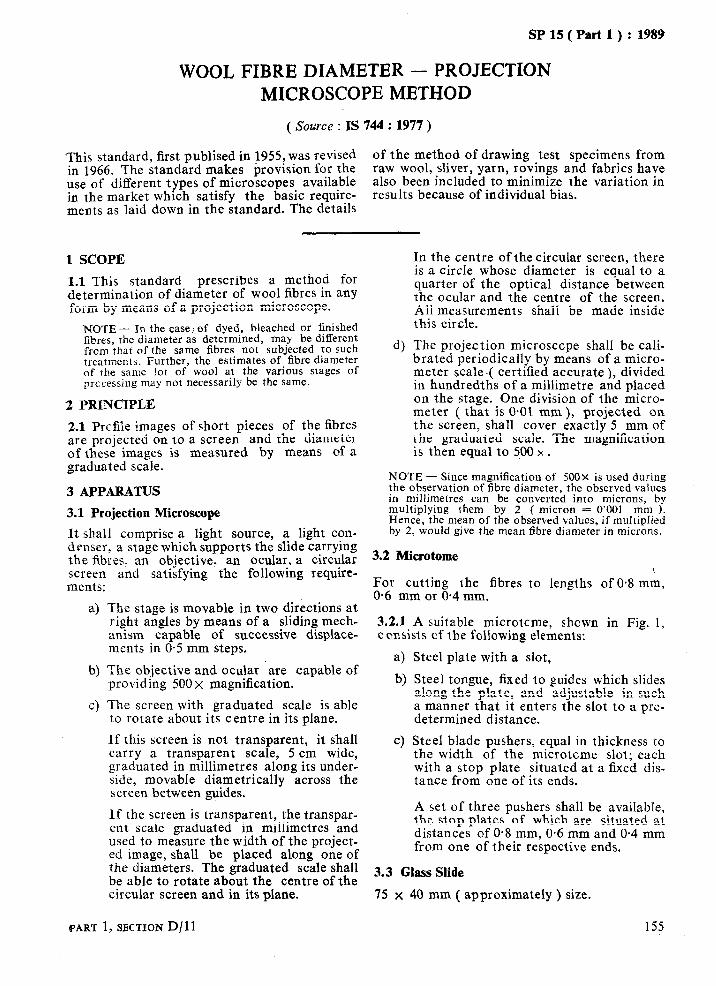
SP 15 ( Part 1 ) : 1989
WOOL FIBRE DIAMETER - PROJECTION MICROSCOPE METHOD
( Source : IS 744 : 1977 )
‘This standard, first publised in 1955, was revised of the method of drawing test specimens from in 1966. The standard makes hrovision for the raw wool, sliver, yarn, rovings and fabrics have use of different types of microscopes available also been included to minimize the variation in in the market which satisfy the basic require- results because of individual bias. meats as laid down in the standard. The details
1 SCOPE
1.1 This standard prescribes a method for determination of diameter of wool fibres in any form by means of a projection microscope.
NOTE - In the case; of dyed, bleached or finished fibres, the diameter as determined, may be different from that of the same fibres not subjected to such treatments. Further, the estimates of fibre diameter of the same lot of wool at the various stages of prccessing may not necessarily be the same.
2 PRINCIPLE
2.1 Prcfile images of short pieces of the fibres are projected on to a screen and the diameter of these images is measured by means of a graduated scale.
3 APPARATUS
3.1 Projection Microscope
It shall comprise a light source, a light con- denser, a stage which supports the slide carrying the fibres, an objective, an ocular,, a circular screen and satisfying the followmg require- ments:
a) The stage is movable in two directions at right angles by means of a sliding mech- anism capable of successive displace- ments in O-5 mm steps.
b) The objective and ocular are capable of providing 500 x magnification.
c) The screen with graduated scale is able to rotate about its centre in its plane.
If this screen is not transparent, it shall carry a transparent scale, 5 cm wide, graduated in millimetres along its under- side, movable diametrically across the screen between guides.
If the screen is transparent, the transpar- ent scale graduated in millimetres and used to measure the width of the project- ed image, shall be placed along one of the diameters. The graduated scale shall be able to rotate about the centre of the circular screen and in its plane.
4
In the centre of the circular screen, there is a circle whose diameter is equal to a quarter of the optical distance between the ocular and the centre of the screen. All measurements shall be made inside this circle.
The projection microscope shall be cali- brated periodically by means of a micro- meter scale-( certified accurate ), divided in hundredths of a millimetre and placed on the stage. One division of the micro- meter ( that is 0.01 mm ), projected on the screen, shall cover exactly 5 mm of the graduated scale. The magnification is then equal to 500 x .
NOTE - Since magnification of 500~ is used during the observation of fibre diameter, the observed values in millimetres can be converted into microns, by multiplying them by 2 ( micron = 0‘001 mm 1. Hence, the mean of the observed values, if multiplied by 2, would give the mean fibre diameter in microns.
3.2 Microtome
For cutting the fibres to lengths of 0.8 mm, 0.6 mm or 0.4 mm.
3.2.1 A suitable microtcme, shown in Fig. 1, consists cf the following elements:
4 b)
Cl
Steel plate with a slot,
Steel tongue, fixed to guides which slides along the plate, and adjustable in such a manner that it enters the slot to a pre- determined distance.
Steel blade pushers, equal in thickness to the width of the microtome slot; each with a stop plate situated at a fixed dis- tance from one of its ends.
A set of three pushers shall be available, the stop plates of which are situated at distances of 0.8 mm, 0.6 mm and 0.4 mm from one of their respective ends.
3.3 Glass Slide
75 x 40 mm ( approximately ) size.
PART 1, SECTION D/11 155
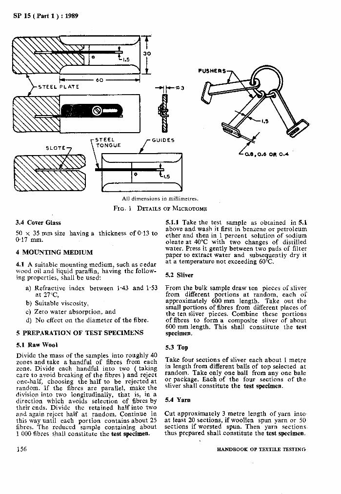
SP 15 ( Part 1) : 1989
All dimensions in millimetres.
FIG. 1 DETAILS OF MICROTOMB
3.4 Cover Glass
50 x 35 mm size having a thickness of 0.13 to 0.17 mm.
4 MOUNTING MEDIUM
4.1 A suitable mounting medium, such as cedar wood oil and liquid paraffin, having the follow- ing properties, shall be used:
a) Refractive index between l-43 and l-53 at 27”C,
b) Suitable viscosity, c) Zero water absorption, and d) No effect on the diameter of the fibre.
5 PREPARATION OF TEST SPECIMENS
5.1 Raw Wool
Divide the mass of the samples into roughly 40 zones and take a handful of fibres from each zone. Divide each handful into two ( taking care to avoid breaking of the fibres ) and reject one-half, choosing the half to be rejected at random. If the fibres are parallel, make the division into two longitudinally, that is, in a direction which avoids selection of fibres by their ends. Divide the retained half into two and again reject half at random. Continue in this way until each portion contains about 25 fibres. The reduced sample containing about 1 000 fibres shall constitute the test specimen.
156
5.1.1 Take the test sample as obtained in 5.1 above and wash it first in benzene or petroleum ether and then in 1 percent solution of sodium oleate at 40°C with two changes of distilled water. Press it gently between two pads of filter paper to extract water and subsequently dry it at a temperature not exceeding 60°C.
5.2 Sliver
From the bulk sample draw ten pieces of sliver from different portions at random, each of approximately 600 mm length. Take out the small portions of fibres from different places of the ten sliver pieces. Combine these portions of fibres to form a composite sliver of about 600 mm length. This shall constitute the test specimen.
5.3 Top
Take four sections of sliver each about 1 metre in length from different balls of top selected at random. Take only one ball from any one bale or package. Each of the four sections of the sliver shall constitute the test specimen.
5.4 Yam
Cut approximately 3 metre length of yarn into at least 20 sections, if woollen spun yarn or 50 sections if worsted spun. Then yarn sections thus prepared shall constitute the test specimen.
HANDBOOK OF TEXTILE TESTING-
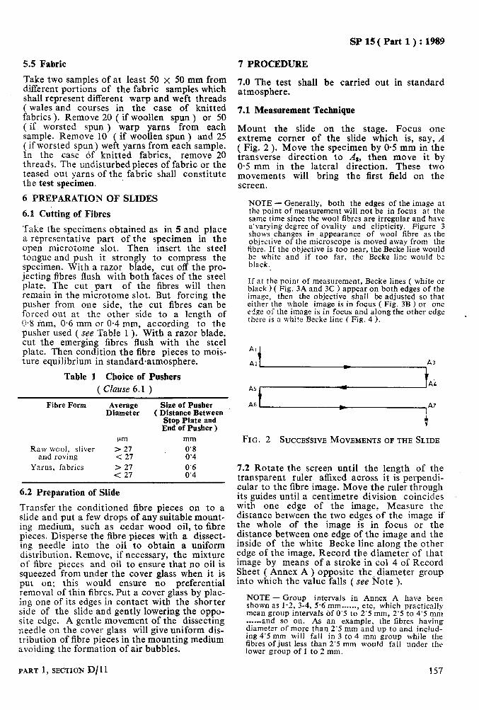
SP15(Pad1):1989
5.5 Fabric 7 PROCEDURE
Take two samples of at least 50 x 50 mm from different portions of the fabric samples which shall represent different warp and weft threads ( wales and courses in the case of knitted fabrics ). Remove 20 ( if woollen spun ) or 50 ( if worsted spun ) warp yarns from each sample. Remove 10 ( if woollen spun ) and 25 ( if worsted spun) weft yarns from each sample. In the case df knitted fabrics, remove 20 threads. The undisturbed pieces of fabric or the teased out yarns of the fabric shall constitute the test specimen.
6 PREPARATION OF SLIDES
6.X Cutting of Fibres
Take the specimens obtained as in 5 and place a representative part of the specimen in the open microtome slot. Then insert the steel tongue and push it strongly to compress the specimen. With a razor blade, cut off the pro- jecting fibres flush with both faces of the steel plate. The cut part of the fibres will then remain in the microtome slot. But forcing the pusher from one side, the cut fibres can be Forced out at the other side to a length of 0.8 inm, 0.6 mm or 0.4 mm, according to the pusher used ( see Table 1 ). With a razor blade, cut the emerging fibres flush with the steel plate. Then condition the fibre pieces to mois- ture equilibrium in standardaatmosphere.
Table 1 Choice of Pushers ( Clause 6.1 )
Fibre Form Average Size of Pusher Diameter ( Distance Between
Stop Plate and End of Pusher )
pm mm Raw wool, sliver > 27 0’8
and roving < 27 0’4 Yarns, fabrics > 27
< 27 8::
6.2 Preparation of Slide
Transfer the conditioned fibre pieces on to a slide and put a few drops of any suitable mount- ing medium, such as cedar wood oil, to fibre pieces. Disperse the fibre pieces with a dissect- ing needle into the oil to obtain a uniform distribution. Remove, if necessary, the mixture of fibre pieces and oil to ensure that no oil is squeezed from under the cover glass when it is put on; this would ensure no preferential removal of thin fibres. Put a cover glass by plac- ing one of its edges in contact with the shorter side of the slide and gently lowering the oppo- site edge. A gentle movement of the dissecting needle on the cover glass will give uniform dis- tribution of fibre pieces in the mounting medium avoiding the formation of air bubbles.
7.0 The test shall be carried out in standard atmosphere.
7.1 Measurement Technique
Mount the slide on the stage. Focus one extreme corner of the slide which is, say, A ( Fig. 2 ). Move the specimen by O-5 mm in the transverse direction to Al, then move it by 0.5 mm in the lateral direction. These two movements will bring the first field on the screen.
NOTE - Generally, both the edges of the image at the point of measurement will not be in focus at the same time since the wool fibres are irregular and have a’varying degree of ovality and elipticity. Figure 3 shows changes in appearance of wool fibre as the objective of the microscope is moved away from the fibre. If the objective is too near. the Becke line would be white and-if too far, the ‘Becke lint would be black.
If at the point of measurement, Becke lines ( white or black ) ( Fig. 3A and 3C ) appear on both edges of the image, then the objective shall be adjusted so that either the whole image is in focus ( Fig. 3B ) or one edge of the image is in focus and along the other edge there is a white Becke line ( Fig. 4 ).
Al i
A5
A6 A7
t
FIG. 2 SUCCESSIVE MOVEMENTS OF THE SLIDE
7.2 Rotate the screen until the length of the transparent ruler affixed across it is perpendi- cular to the fibre image. Move the ruler through its guides until a centimetre division coincides with one edge of the image, Measure the distance between the two edges of the image if the whole of the image is in focus or the distance between one edge of the image and the inside of the white Becke line along the other edge of the image. Record the diameter of that image by means of a stroke in co1 4 of Record Sheet ( Annex A) opposite the diameter group into which the value falls ( see Note ).
NOTE - Group intervals in Annex A have been shown as l-2, 3-4, 5-6 mm......, etc, which practically mean group intervals of 0’5 to 2’5 mm, 2’5 to 4’5 mm . . ..-and so on. As an example, the fibres having diameter of more than 2’5 mm and up to and includ- ing 4’5 mm will fall in 3 to 4 mm group while the fibres of just less than 2’5 mm would fall under the lower group of 1 to 2 mm.
PART 1, SECTION D/ 11 157

SP 15 ( Part 1) : 1989
A 6 C
A-Objective Too Near ( White Becke Lines 1 B-Fibre in Focus ( No Becke Lines )
C-Objective Too Far Away (Black Becke Lines )
FIG. 3 CHANGB IN APPEARANCE OF WOOL FIBRE [AS THE OBJECTIVE IS~~;ED AWAY FROM THE
Correct Incorrect
FIG. 4 CORRECTLY FOCUSED FIBRE WITH ONE SHARP EDGE AND WHITE BBCKE LINE, AND
INCORRECTLY FOCUSED FIBRE WITH BLACK BECKE LINE
7.3 Observe the following conventions in mea- suring the fibre diameter:
a) Measurement shall not be made:
1) at a point where fibre images cross one another.
2) if the extremities of the image do not project beyond the lengthwise edges of the transparent ruler,
3) if the length of the image appears to be less than the diameter of the circle on the screen,
4) if the image shows the fibre to be longitudinally damaged, and
5) if the image has more than half its width outside the circle on the screen.
NOTE - The stage shall remain stationary during the measurement in a given field. It may happen that in a field there will be no fibre at all or only one or two.
7.4 When the fibres have been measured in one field, move the slide 0.5 mm in the lateral direction, measure the fibres in the new field as in 7.2. Continue in this way along the whole length of the slide. Havingreached As, move the slide by 0.5 mm in the transverse direction to A4 and continue measuring laterally in 0.5 mm steps and so on. Cover the whole slide in this way, following the path A,, A,, As, Ad, A,, A6, A7......( see Fig. 2 ).
7.5 Repeat the process until at least 200 obser- vations have been made and recorded ( see Annex A ). Calculate the variance ( Si2 ).
7.6 The sample size required to obtain an esti- mate of mean fibre diameter within the desired limit with 95 percent probability level is given by the following formula:
ts s.a - -1
n=E’ where
II - number of observations, t = 1.96,
Sr’ = variance as calculated in 7.5, and E = desired limit in microns.
7.7 If the sample size so obtained is greater than 200, prepare another slide(s) to obtain the required number of observations (n) as obtained in 7.6.
7.8 Calculate the mean fibre diameter, the standard deviation and percent coefficient of variation of the sample to two decimal places as described in Annex B.
8 REPORT
8.1 Report shall include the following informa- tion:
a) Type of material, b) Mean fibre diameter, and cl Number of observations.
158 HANDBOOK OF TEXTILE TESTING

SP 15 ( Part 1 ) : 1989
SI NO.
(1)
1.
2.
3.
4.
5.
6.
7.
8.
Diameter
(2)
mm
l-2
3-4
5-6
7-8
9-10
II-12
13-14
15-16
Mid Values
(3)
mm
ANNEX A ( Clauses 7.2 and 7.5 )
RECORD SHEET
Observed Frequency f
(4) (5)
1
3
4
19
d fd fdr
(6) (7) (8)
-5 -5 25
-4 -12 48
-3 -12 36
-2 -38 76 _- 1 15*5 #flfccHGHHcIf#u#)cH 35 -35 35
9. 17-18 17.5 fWWfff#f!ffWffffi1111 39 0 0 0
10. 19-20 19.5 uWfffffWfufff/ff//ffuI 36 1 36 36
14. 21-22 21.5 ft))Wfu ffUfU+ 25 2 50 100
12. 23-24 23.5 fft) ff)) Ii 12 3 36 108
13. 25-26 25.5 ff# f# 10 4 40 160
14. 27-28 27.5 f/f# /i 7 5 35 175
15. 29-30 29.5 +ltt 5 6 30 180
16. 31-32 31.5 II 2 7 14 98 17. 33-34 33.5 I 1 8 8 64
18. 35-36 35.5 I 1 9 9 81
19. 37-38 37.5
n= cfd Zfd” Ef = 200 ~156 =l 222
ANNEX B ( Clause 7.8 )
METHOD OF CALCULATION OF MEAN FIBRE DIAMETER, VARIANCE, COEFFICIENT OF VARIATION AND NUMBER OF OBSERVATIONS
B-l PROCEDURE Note in co1 6 the deviation ‘d’ of each group
B-l.1 Fill in co1 5 of the Record Sheet value from the assumed origin ‘Do’ expressed in
( Annex A ) the total number of strokes against the unit of class interval ‘c’, prefixing ‘+’ or ‘ __,
each diameter group. sign, whichever is applicable. For example,
the assumed origin of the values recorded in
B-1.2 Find out diameter group with the highest Annex A ls 17’5 mm* frequency, and take the centre ( or mid-value ) of this diameter group as the assumed origin.
B-l.3 Derive the values of ‘fd’ and ‘fde’ from the values noted in co1 5 and 6 of the Record
PART 1, SECTION D/ 11 159
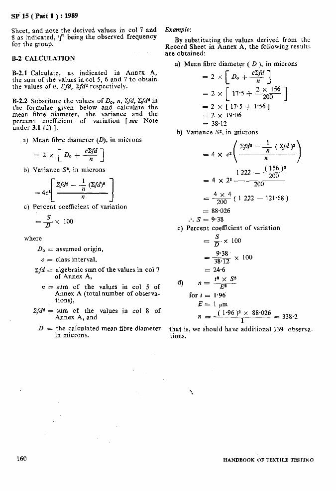
SP 15 ( Part 1) : 1989
Sheet, and note the derived values in co1 7 and Example: 8 as indicated, ‘f’ being the observed frequency for the group. By substituting the values derived from the
Record Sheet in Annex A, the following results
B-2 CALCULATION are obtained:
a) Mean fibre diameter ( D ), in microns B-2.1 Calculate, as indicated in Annex A, the sum of the values in co1 5, 6 and 7 to obtain the values of n, tlfd, 2fdY respectively.
B-2.2 Substitute the values of D,,, II, Zfd, Xfd* in the formulae given below and calculate the mean fibre diameter, the variance and the percent coefficient of variation [ see Note under 3.1 (d) 1:
a) Mean fibre diameter (D), in microns
=2x Doi-- c
cXfd 1 b) Variance St, in microns
c) Percent coefficient of variation
=4x 100
where
D, = assumed origin,
c = class interval,
zifd = algebraic sum of the values in co1 7 of Annex A,
n = sum of the values in co1 5 of Annex A (totalnumber of observa- tions),
2fd2 = sum of the values in co1 8 of Annex A, and
D = the calculated mean fibre diameter in microns.
160 HANDBOOK OF TEXTILE TESTING
=2x D,+Td [ 1
= 2 x ‘- 17.5 + 2 zoo156 t 3
= 2 x [ 17.5 + 1.56 ] = 2 x 19.06 = 38.12
b) Variance Ss, in microns
Efde - + ( xfd )” =4x c3
n
( 156)s 1222 - ___ =4x2a
200 200
= s ( 1 222 - 121.68 )
= 88.026 :. S = 9.38
c) Percent coefficient of variation
= &K 100
=gg x 100
= 24.6
4 ta x se
n=E’ for t = 1.96
E = 1 pm
n = ( 1.96 )’ X 88.026 1
E_ 338.2
that is, we should have additional 139 observa- tions.
.

SP 15 ( Part 1) : 1989
WOOL FIBRE DIAMETER BY AIRFLOW METHOD
( Source : IS 6919 : 1973 )
There is a close correlation between the air permeability of a uniformly arranged mass of
using airflow instruments. Owing to the speed
textile fibres and the specific area ( area/ and simplicity of the method, it is particularly
volume ). For fibres of circular or near circular suitable for quality control in the mills.
cross section and constant density, such as This method is in line with IS0 1136-1976 ‘Air unmedullated wool fibres, the surface area of permeability method for measuring the mean .a given mass of fibres is inversely proportional to the average fibre diameter. This relationship
diameter of wool fibres’ issued by the Interna- tional Organization for Standardization.
is used for determining the wool fibre diameter
1 SCOPE
1.1 This standard prescribes a method for determining the mean diameter of wool fibres using airflow instruments.
1.2 This method is applicable to clean un- medullated wool fibres dispersed in a uniform open state. It is particularly suitable for com- bed slivers. The method is also applicable to oil combed slivers without cleaning, if the oil content is constant and the apparatus suitably calibrated. It is not applicable to samples con- taining medullated fibres and fibres which are heterogeneous in diameter.
2 PRINCIPLE
2.1 A specified mass of fibres to be tested is compressed to a constant volume in a cylindri- cal chamber with perforated ends to which a flowmeter and a manometer are connected. The fibres are packed in such a way that they lie predominantly at right angles to the axis of the chamber. A regulated current of air is then passed through the compressed fibres and the average fibre diameter read off from a scale on the manometer or the flowmeter.
3 APPARATUS
3.1 Airflow Apparatus
Any of the two alternative forms of apparatus, namely, ‘Constant Flow’ and ‘Constant Pressure’ as described below may be used. Both forms of apparatus have the same arrangement of parts, as illustrated in Fig. 1:
a) Constant Flow Apparatus - utilizes a speci- men mass of 15 g, the flowmeter is adjusted to a lixed value and the mean fibre diameter is read off from the mano- meter scale. The scale is not linear since the successive intervals, corresponding to one micrometer ( micron ) decrease with the diameter.
b) Constant Pressure Apparatus - utilizes a specimen mass of 2.5 g, the manometer is adjusted to a fixed pressure and the
PART 1,SECTION D/12
mean fibre diameter is read off from the flowmeter. In practice this apparatus has been found to be somewhat more useful for routine work.
3.2 The apparatus consists of the following parts as shown in Fig. 1.
3.2.1 Air Value ( B)
giving sufficiently fine control of the air supply, such that the level of the flowmeter on mano- meter may be quickly adjusted to the working value.
‘UMP
FIG. 1 GENERAL ARRANGEMENT OF APPARATUS
3.2.2 Suction Pump
of a type providing a smooth output of at least 30 l/min at 200 mm head of water with mini- mal fluctuation of the float of the flowmeter. A filter to trap any loose fibres may be inserted between the pump and the air valve ( B).
3.2.3 Constant Volum+hamber ( A ) -7 .!
of brass, hardened steel, or any other suitable metal, suggested dimensions P;of which are given in Fig. 2. This comprises .three parts, namely, (a) the base into which the fibres are packed, (b) the plunger which compresses the
161
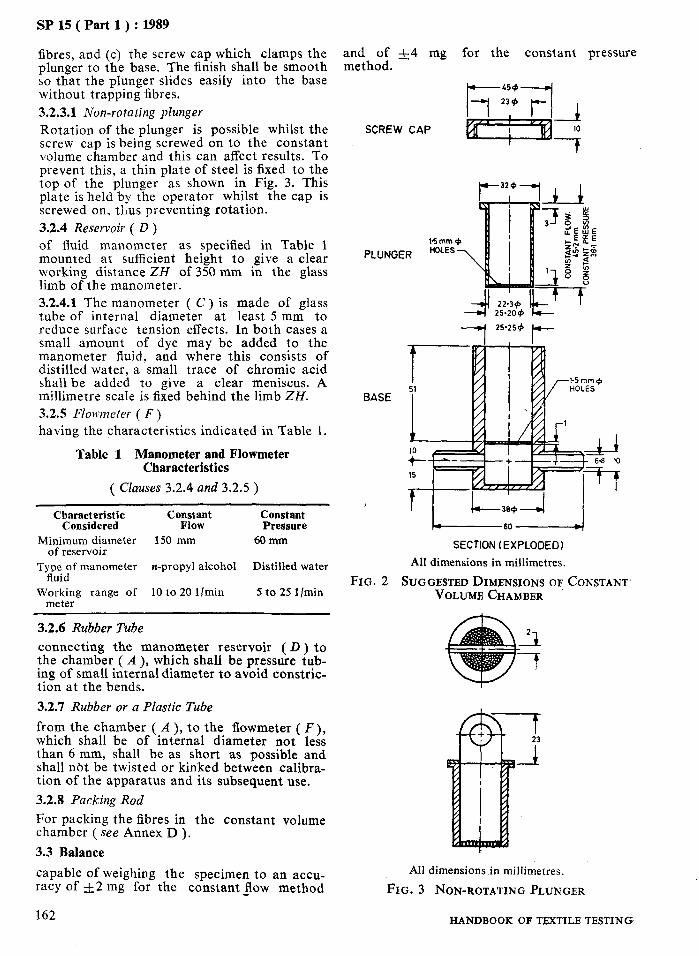
SP 15 ( Part 1) : 1989
fibres, and (c) the screw cap which clamps the plunger to the base. The finish shall be smooth so that the plunger slides easily into the base without trapping fibres. 3.2.3.1 Non-rotating plunger
Rotation of the plunger is possible whilst the screw cap is being screwed on to the constant volume chamber and this can affect results. To prevent this, a thin plate of steel is fixed to the top of the plunger as shown in Fig. 3. This plate is held by the operator whilst the cap is screwed on, thus preventing rotation. 3.2.4 Reservoir ( D )
and of f4 mg for the constant pressure method.
SCREW CAP
of fluid manometer as specified in Table 1 mounted at sufficient height to give a clear working distance ZH of 350 mm in the glass limb of the manometer. 3.2.4.1 The manometer ( C ) is made of glass tube of internal diameter at least 5 mm to reduce surface tension effects. In both cases a small amount of dye may be added to the manometer fluid, and where this consists of distilled water, a small trace of chromic acid shall be added to give a clear meniscus. A millimetre scale is fixed behind the limb ZH. 3.2.5 Flowmeter ( F)
having the characteristics indicated in Table 1.
PLUNGER
BASE
Table 1 Manometer and Flowmeter Characteristics
( Clauses 3.2.4 and 3.2.5 )
Characteristic Constant Constant Considered Flow Pressure
Minimum diameter 150 mm 60 mm of reservoir
Type of manometer n-propyl alcohol Distilled water fluid
Working range of 10 to 20 l/min meter
5 to 25 l/min
SECTION (EXPLODED)
All dimensions in millimetres.
FIG. 2 SUGGESTED DIMENSIONS OF CONSTANT. VOLUME CHAMBER
3.2.6 Rubber Tube
connecting the manometer reservoir ( D ) to the chamber ( A ), which shall be pressure tub- ing of small internal diameter to avoid constric- tion at the bends.
3.2.7 Rubber or a Plastic Tube
from the chamber ( A ), to the flowmeter ( F ), which shall be of internal diameter not less than 6 mm, shall be as short as possible and shall nbt be twisted or kinked between calibra- tion of the apparatus and its subsequent use. 3.2.8 Packing Rod
For packing the fibres in the constant volume chamber ( see Annex D ), 3.3 Balance
capable of weighing the specimen to an accu- All dimensions in millimetres.
racy of 3~2 mg for the constant Jlow method FIG. 3 NON-ROTATING PLUNGER
162 HANDBOOK OF TEXTILE TESTING

4 PREPARATION OF TEST SPECIMENS
4.1 Cleaning ’
The laboratory sample shall be about 8 g and shall first be degreased by rinsing well in the baths each of about 200 ml of petroleum ether before conditioning. If the laboratory sample is known to be dry-combed with fatty matter content below 1 percent, the test specimens may be taken from it without cleaning. If the laboratory sample is known to be oily with fatty matter content between 3 and 4 percent, the test specimens may be taken from it with- out cleaning provided the apparatus has been calibrated from oil-combed slivers.
4.2 Number of Specimens
Unless otherwise specified, test a minimum of two specimens for fibre diameter below 30 pm and a minimum of three specimens for fibre diameter above 30 ccm.
4.3 Selection of Specimens
Take the specimens from different places in the laboratory sample. In the case of balls of sliver, the laboratory sample should be made up of yFec;s.lyf sliver from both inside and outside of
4.4 Specimen Mass
For the constant flow method the specimen mass should be 1.5 g f 2 mg. For the constant pressure method the specimen mass should be 2.5 g f 4 mg.
4.5 Preparation
For slivers with cut ends, cut off with scissors a length to give as nearly as possible the speci- men mass, then make up to the exact mass by adding shorter cut lengths or portions. For slivers with pulled ends, remove and discard about live hand draws, then weigh out the specimens by taking several successive hand draws.
5 PROCEDURE
5.0 If tests are not carried out in the standard atmosphere for testing, condition the labora- tory’sample to moisture equilibrium near the apparatus.and note the relative humidity of the
’ atmosphere at the time of test, then correct the final results by the factors given in Annex B.
5.0.1 The readings of flowmeters are influenced to a small extent by variations in barometer pressure and temperature. Correction plugs ( see A-3.4 ) may be used if the variations in barometric pressure and temperature are .appre- ciable at the place of testing.
PART 1, SECTION D/12
SP 15 ( Part 1 ) : 1989
5.1 Ensure that the meniscus of the manometer is at the zero mark and, if required, carry out an orifice plate check as given in A-3.3.
5.2 Pull out the weighed test specimen into a long thin sliver and feed it evenly into the con- stant volume chamber ( A ), packing the fibres down with the packing rod from time to time. Insert the plunger and screw down the cap to the furthermost extent so that the lip of the plunger is in contact with the base.
5.3 Depending on the method to be used, adjust the air valve as follows:
a>
b)
For constant flow method adjust the air valve until the top of the float of the flowmeter coincides with the reference mark Y and note the fluid level of the manometer to the nearest millimetre or 0.1 pm ( see A-3.1 ). For constant pressure method adjust the air valve until the fluid level of the mano- meter coincides with the 18 cm reference mark H and note the position of the float of the flowmeter to the nearest millime- tre or O-1 micron ( see A-3.2 ).
5.4 Remove the specimen from the constant volume chamber, tease out the fibres by hand, repack in the constant volume chamber with- out loss of fibres, insert the plunger and screw down the cap, and note the reading again as before.
5.5 Repeat the operation 5.4 so that a total of three readings on each test specimen is obtained.
5.6 Similarly test the other test specimens as given above.
6 CALCULATIONS
6.1 Calculate the average of the three readings for each specimen and then average of the readings for all test specimens and express the result to the nearest 0.1 pm.
7 REPORT
7.1 The report shall include the following information:
4 b) cl 4
e) f 1
Type of material, Name of the apparatus used, Number of test specimens tested, Whether the specimen was tested after cleaning or without cleaning, Average fibre diameter, and Whether tested in standard atmosphere or correction applied for relative humi- dity.
163
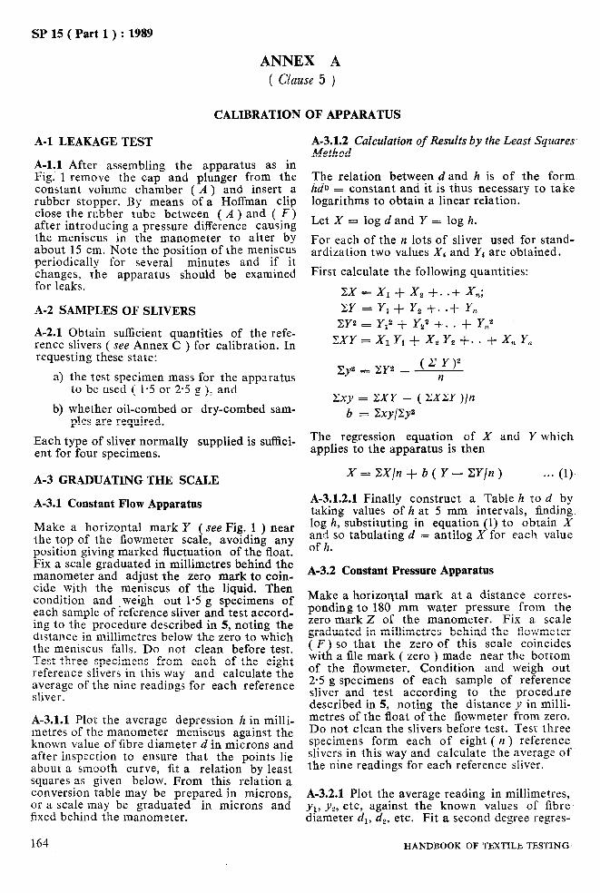
SP 15 ( Part 1) : 1989
ANNEX A ( Clause 5 )
CALIBRATION OF APPARATUS
A-l LEAKAGE TEST
A-l:1 After assembling the apparatus as in Fig. 1 remove the cap and plunger from the constant volume chamber ( A ) and insert a rubber stopper. By means of a Hoffman clip close the rubber tube between ( A ) and ( F) after introducing a pressure difference causing the meniscus in the manometer to alter by about 15 cm. Note the position of the meniscus periodically for several minutes and if it changes, the apparatus should be examined for leaks.
A-2 SAMPLES OF SLIVERS
A-2.1 Obtain sufficient quantities of the refe- rence slivers ( see Annex C ) for calibration. In requesting these state:
a) the test specimen mass for the apparatus to be used ( 1.5 or 2.5 g ), and
b) whether oil-combed or dry-combed sam- ples are required.
Each type of sliver normally supplied is suffici- ent for four specimens.
A-3 GRADUATING THE SCALE
A-3.1 Constant Flow Apparatus
Make a horizontal mark Y ( see Fig. 1 ) near the top of the flowmeter scale, avoiding any position giving marked fluctuation of the float. Fix a scale graduated in millimetres behind the manometer and adjust the zero mark to coin- cide with the meniscus of the liquid. Then condition and ,weigh out 1.5 g specimens of each sample of reference sliver and test accord- ing to the procedure described in 5, noting the distance in millimetres below the zero to which the meniscus falls. Do not clean before test. Test three specimens from each of the eight reference slivers in this way and calculate the average of the nine readings for each reference sliver.
A-3.1.1 Plot the average depression h in milli- metres of the manometer meniscus against the known value of fibre diameter d in microns and after inspection to ensure that the points lie about a smooth curve, fit a relation by least squares as given below. From this relation a conversion table may be prepared in microns, or a scale may be graduated in microns and fixed behind the manometer.
164
A-3.1.2 Calculation of Results by the Least Squares Method
The relation between d and h is of the form hdb = constant and it is thus necessary to take logarithms to obtain a linear relation.
Let X = log d and Y = log h.
For each of the n lots of sliver used for stand- ardization two values Xi and Y1 are obtained.
First calculate the following quantities:
zx=x,+x,+..+x,; ZY = Yi + Y, f. .+ Y,
CY2 = Yi’ i Ysa +. . + Y,2
zxY=x~Y*+x,Y*+..+x,Y,,
zy2 = BY2 - (zY)2 n
cxy = ZXY - ( ZXCY )/n b = %y/By2
The regression equation of X and Y which applies to the apparatus is then
X=X/n+b(Y--Y/n) *** (1)
A-3.1.2.1 Finally construct a Table h to d by taking values of h at 5 mm intervals, finding log h, substituting in equation (1) to obtain X and so tabulating d = antilog X for each value of h.
A-3.2 Constant Pressure Apparatus
Make a horizontal mark at a distance corres- ponding to 180 mm water pressure from the zero mark Z of the manometer. Fix a scale graduated in millimetres behind the flowmeter ( F) so that the zero of this scale coincides with a file mark ( zero ) made near the bottom of the flowmeter. Condition and weigh out 2.5 g specimens of each sample of reference sliver and test according to the procedure described in 5, noting the distance y in milli- metres of the float of the flowmeter from zero. Do not clean the slivers before test. Test three specimens form each of eight ( II ) reference slivers in this way and calculate the average of the nine readings for each reference sliver.
A-3.2.1 Plot the average reading in millimetres, yl, yl, etc, against the known values of fibre diameter dl, d,, etc. Fit a second degree regres-
HANDBOOK OF TBXTILE TISSTING
t

r ---- SF 15 ( Part 1 ) : 1989
sion line of y on d. This is done by finding the coefficients a, b, c, in the equation
Y = a + bd + cda . . . (2) by solving the equations :
Zy = na + bZd x cCdz
Zdy = aCd + bZd2 f cgd3
Zd”y = aBd2 + bZd3 + cZd4
The equation (2) is then used to graduate a scale in microns which may be fixed behind the flowmeter.
A-3.3 Orifice Plate Checks
To make regular daily checks that the appa- ratus is in good order the use of two orifice plates is recommended. These consist of alumi- nium discs of the same diameter as the inside of the constant volume chamber, each with a central hole. The discs have a rim which in use rests on the annular top of the constant volume chamber. The diameter of the central hole in one disc is chosen to give a reading of about one-third of the available scale on the mano- meter ( constant flow method ) of flowmeter ( constant pressure method ) when clamped and used in the apparatus under working condi- tions, with no fibres in the chamber. The dia- meter of the central hole ih the second disc is chosen to give a reading ef about two-thirds of the available scale, under the above described conditions.
A-3.3.1 At least once a dry orifice plates are clamped in the apparatus so that air enters through the central hole only and the readings are noted. Variations in the readings given by the scale should not exceed 2 mm and 4 mm respectively for the two orifice platesi This provides a useful and quick check on the func- tioning of the apparatus, particularly as regards the presence of air bubbles in the manometer system.
A-3.4 Correction Plugs
A combined correction for both temperature and barometric pressure may be made by the aid of a plug filled with non-hygroscopic fibre, for example, polyester. Details of the construc- tion are given in Fig. 4. The plug is filled with the correct mass* of non-hygroscopic fibre and
*The correct mass of non-hygroscopic fibre in grams is given by 1’5~11’31 for constant flow and 2’5p/1’31 for constant pressure where p = density of fibre and density of wool assumed to be 1’31. For polyester the correct mass will be 1’58 g for constant flow and 2’63 g for constant pressure.
the top of the plug sealed permanently with a resin which sets at sufficiently low temperature to avoid damaging the fibres ( for example, 100°C ). The plug is clamped in place of the metal plunger on the airflow apparatus and the instrument reading taken several times at 27°C when the barometric pressure is within 5 mm Hg of the pressure at calibration. Let the’ mean reading be C pm. During any series of subsequ- ent tests the plug is inserted .and a reading taken. Let this be T pm. Then the results of any tests are multiplied by the factor C/r.
NOTE -A thin rubber or plastic sealing ring of internal diameter 25’2 mm is placed under the rim .of the plug SO there is no edge leakage when clamped in position on the constant volume chamber.
PLAN
bSrnrn* HOLES
3-I )c32d- r0.7
CONSTANT FLOW 9-2mm *_l CONSTANT PRESSURE 17.3 mm
SECTIONAL FRONT
1.5 mm+ HOLES
BOTTOM VIEW
All dimensions in miilimetres.
FIG. 4 DIMENSIONS OF CORRECTION PLUG
A-3.4.1 With long usage of the plug, dirt depo- sits and the reading of the plug changes. It is advised, therefore, that after it has been used about 400 times ( 18 months if used once per day ) the non-hygroscopic fibre be replaced by clean fibre and a new standard reading for the plug be determined. Likewise the plug shall be kept in a protective container when not in use and should be discarded if it has been in con- tact with any liquid, powder, etc.
PART 1, SECTION D/12 165
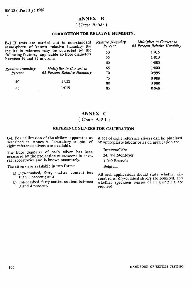
SP 15 ( Part 1) : 1989
ANNEX B ( Clause A-5.0 j
CORRECTION FOR RELATIVE HUMIDITYI
B-l If tests are carried out in non-standard atmosphere of known relative humidity the results in microns may be corrected by the following factors, applicable to fibre diameters between 19 and 37 microns:
Relative Humidity Multiplier to Convert to Percent 65 Percent Relative Humidity
40 1.022
45 1.019
Relative Humidity Multiplier to Convert to Percent 65 Percent Relative Humidity
50 l-015
55 1.010 60 1.005 65 l+NO 70 0.995 75 0.988 80 0.980 85 0.969
ANNEX C ( Clause A-2.1 )
REFERENCE SLIVERS FOR CALIBRATION
C-l For calibration of the airflow apparatus as described in Annex A, laboratory samples of
A set of eight reference slivers can be obtained
eight reference slivers are available. by appropriate laboratories on application to:
The fibre diameter of each sliver has been Interwoollabs
measured by the projection microscope in seve- 24, rue Montoyer ral laboratories and is known accurately. 1 040 Brussels The slivers are available in two forms: Belgium
a) Dry-combed, fatty matter content less than 1 percent; and All such applications should state whether oil-
b) Oil-combed, fatty matter content between combed or dry-combed slivers are required, and
3 and 4 percent. whether specimen masses of 1.5 g or 2.5 g are required.
166 HANDBOOK OF TEXTILE TESTING
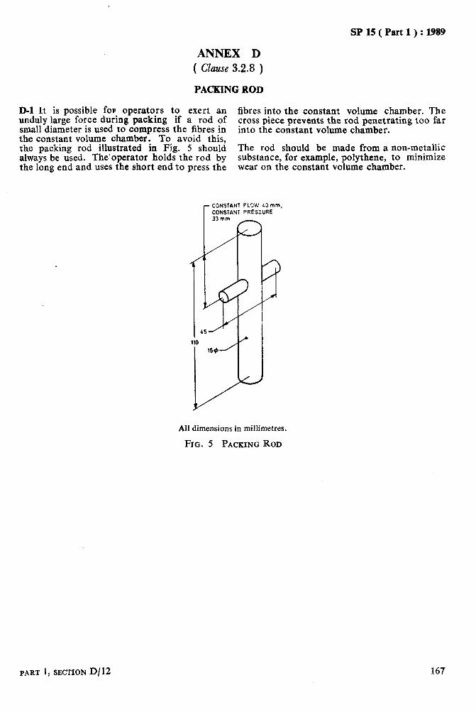
SP 15 ( Part 1 ) : 1989
ANNEX D ( Clause 3.2.8 )
PACKING ROD
D-l It is possible for operators to exert an fibres into the constant volume chamber. The unduly large force during packing if a rod of small diameter is used to compress the fibres in
cross piece prevents the rod penetrating too far into the constant volume chamber.
the constant volume chamber. To avoid this, the packing rod illustrated in Fig. 5 should The rod should be made from a non-metallic always be used. The’operator holds the rod by substance, for example, polythene, to minimize the long end and uses the short end to press the wear on the constant volume chamber.
All dimensions in millimetres.
FIG. 5 PACKING ROD
PART 1, SECTION D/12 167

As in the Original Standard, this Page is Intentionally Left Blank
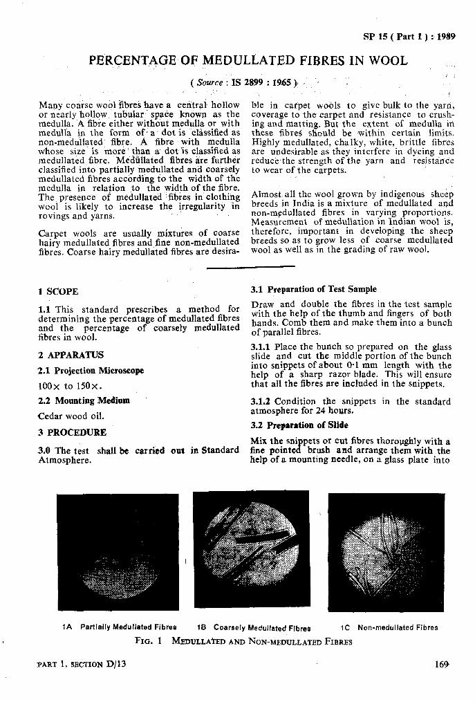
:, 1989 SP 15 ( Part 1 )
PERcEFJT,i)GE OF MEDULLATED FIBRES -IN WOOL
( Source : IS 2899 : 1965 )f , -, . . .
Many coarse wool $ibres have a celitrai hollow or nearly hollow, tubular spa&e known as the medulla. A fibie either without medulla or with medulla in the form of’ a dot is clirssified as non-medullated fibre. A fibre with medulla whose size iS niore than a dot ‘is classified as medullated fibre. Mediillated fibres are further classified i&o partially medullated and coarsely medullated fibres according io the width of the me,dulla in relation jo the, width of the fibre. The presence of medullated fibres in clothing wool is likely to increase the i,rregularity in rovings and yarns.
ble in catpet wobls to give bulk to the yarri, coverage to the carpet and resistance to crush- ing and matting. But the extent of medulla in these fibres: should be within certain limits. Highly medullated, chalky, white, brittle fibres are undesirable as they interfere in dyeing and 4
reduce the strength of the yarn and resistance to wear of the carpets.
Carpet wools are usually mixtures of coarse hairy medullated fibres and fine non-medullated fibres. Coarse hairy medullated fibres are desira-
Almost all the wool grown by indigenous sheep breeds in India is a mixture of medullated and non-mgdullated fibres in varying proportions. Measurement of medullation in Indian wool is, therefore, important in developing the sheep breeds so as to grow less of coarse medullated wool as well as in the grading of raw wool.
1 SCOPE
1.1 This standard prescribes a method for determining the percentage of medullated fibres and the percentage of coarsely medullated fibres in wool.
2 APPARATUS
2.1 Projection Microscope
100x to 150x.
2.2 Mounting Medium
Cedar wood oil.
3 PROCEDURE
3.0 The t&t shall be carried out in Standard Atmosphere.
3.1 Preparation of Test Sample
Draw and double the fibres in the test sample with the help of the thumb and fingers of both hands. Comb them and make them into a bunch of parallel fibres.
3.1.1 Place the bunch so prepared on the glass slide and cut the middle portion of the bunch into snippets of about 0.1 mm length with the help of a sharp razor blade. This will ensure that all the fibres are included in the snippets.
3.1.2 Condition the snippets in the standard atmosphere for 24 hours.
3.2 Preparation of Slide
Mix the sni fine pointe a
pets or cut fibres thoroughly with a brush and arrange them with the
help of a mounting needle, on a glass plate into
1A Partially Msdullded Fibres
FIG. 1 MEDTJLLA~ED AND NON-MEDULLATED FIBRES
PART 1, SECTION D/13 169
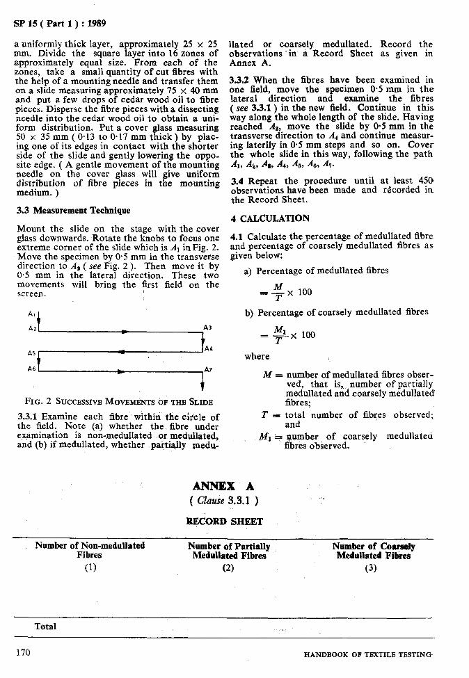
x SP 15 ( Part 1) : 1989
a uniformly thick layer, approximately 25 x 25 mm. Divide the square layer into 16 zones of approximately equal size. From each of the zones, take a small quantity of cut fibres with the help of a mounting needle and transfer them on a slide measuring approximately 75 x 40 mm and put a few drops of cedar wood oil to fibre pieces. Disperse the fibre pieces with a dissecting needle into the cedar wood oil to obtain a uni- form distribution. Put a cover glass measuring 50 x 35 mm ( 0.13 to O-17 mm thick) by plac- ing one of its edges in contact with the shorter side of the slide and gently lowering the oppo- site edge. ( A gentle movement of the mounting needle on the cover glass will give uniform distribution of fibre pieces in the mounting medium. )
3.3 Measurement Technique
Mount the slide on the stage with the cover glass downwards. Rotate the knobs to focus one extreme corner of the slide which is At inFig. 2. Move the specimen by 0.5 mm in the transverse direction to AB ( see Fig. 2 ). Then move it by 0.5 mm in the lateral direction. These two movements will bring the first field on the screen.
FIG. 2 SUCCESSIVE MOVEMENTS OF THE SLIDE
3.3.1 Examine each fibre within the circle of the field. Note (a) whether the fibre under examination is non-medullated or medullated, and (b) if medullated, whether paitially medu-
llated or coarsely medullated. Record the observations .in a Record Sheet as given in Annex A.
3.3.2 When the fibres have been examined in one field, move the specimen 0.5 mm in the lateral direction and examine the fibres ( see 3.3.1) in the new field. Continue in this way along the whole length of the slide. Having reached As, move the slide by 0.5 mm in the transverse direction to A, and continue measur- ing laterlly in 0.5 mm steps and so on. Cover the whole slide in this way, following the path AI, Al,, Aa, A,, & &, -47.
3.4 Repeat the procedure until at least 450 observations have been made and recorded in the Record Sheet.
4 CALCULATION
4.1 Calculate the percentage of medullated fibre and percentage of coarsely medullated fibres as given below:
a) Percentage of medullated fibres
=$x 100
b) Percentage of coarsely medullated fibres
= qx 100
where
M = number of medullated fibres obser- ved, that is, number of partially medullated and coarsely medullated fibres;
T = total number of fibres observed; and
: jtfl + number of coarsely medullated fibres observed.
ANNEX k ( czuml? 3.3.1 ) -”
RECORD SHEET
Number of Non-medullated Fibres
Number of Partially Medullated Fibres
(1) (2)
Namber of Coarsely Medullated Fibres
(3)
Total
170 HANDBOOK OF TEXTILE TESTING

SP 15 ( Part 1) : 1989
MEAN FIBRE LENGTH OF WOOL
( Source : IS 1377 : 1971)
Fibre length is one of the factors on which the wools not suitable for combing are spun into spinning quality of wool depends; generally speaking, longer wools are combed and spun
coarse woollen yarn. Wool fibre is not straight; its crimps and curls complicate measurement of
into comparatively fine worsted yarn and short length.
,
1 SCOPE
1.1 This standard prescribes a method for determining the mean fibre length of wool.
2 PREPARATION OF TEST SPECIMEN
2.1 Mix the gross sample thoroughly, spread out as evenly as possible, and mark it into zones by means of an adjustable sampling frame [ see 4.1 (a) 1. From the central portion of each zone and without disturbing the arrangements of fibres in a stable, draw a small quantity of wool, say about 5 mg, so as to yield a total of about 0.5 g. Without disturbing the arrange- ments of fibres in a staple, spread the wool so drawn evenly over a distance of about 8 cm along the length of a velvet board, keeping the root ends of fibres in the same direction. Cover the root ends of the fibres with a steel rule and draw a bunch of about 100 fibres from under each one of the middle three 2-cm markings of the rule. Each bunch so drawn shall constitute a test-specimen. The bunches taken together, shall constitute the test sample.
3 REAGENT
3.1 Methyl Ether or Benzene
’ 4 APPARATUS
4.1 For the purpose of this test, the following apparatus shall be used:
a) Sampling Frame - consisting of an adjus- table wooden or metal frame of suitable size and fitted with elastic cords along its length and width ( see Fig. 1 ).
b) Veher Board - of black or any other con- trasting colour.
c) Two Pairs of Forceps
d) Scale - graduated in centimetres and millimetres.
5 PROC!EDURE
5.0 The tests shall be carried out in standard atmosphere.
PART 1,SBCTION D/14
P!on Of Sampling Frame Showing
Edges of Wool Somple Evened upto Markers
i [Table -~ b%ol Sample
E?lcrged Section of One P.rlgie Oar 01 Sampiing Frome with Marker and
Wool Sample in Position
FIG. 1 SAMPLING FRAME
5.1 Degrease a test specimen either in 2 changes of methyl ether at room temperature or 3 changes of benzene warmed at 40°C. Draw the wool fibres by hand and form them into a bunch, with the root ends of fibres lying in one direction. Tie the bunch loosely near the root ends of the fibres and place it on the table. Cover the tip ends of fibres under light pressure to facilitate drawing out of fibres one by one.
171
SP 15 ( Part 1 ) : 1989
5.2 Draw one fibre from..the bunch and s&&h’- ,6&l Ifthe stanoard error of the mean is less ten it out by means of the pairs of forceps, than 5 percent of the mean, report correct to taking care not to stretch it but merely to remove its crime. Place it on the velvet board
the nearest millimetre, the mean fibre length
and measure iis length from end to end by obtained as in 6.1.
means of scale correct to one millimetre. Simi- 6.1.2 If the standard error, of the mean is equal I&ly measure the length of each fibre in the to or more than 5 percent of the mean, make at bunch. least 300 further observations.
7 REPORT 5.3 Test at least two more test specimens in a similar manner as in 5.1 and 5.2. 7.1 The report shall include the following
information:
6 CALCULATIONS
6.1 Calculate the mean fibre length, the stand- ard deviation, the coefficient of variation and the standard error of the mean of all the observed values.
a) Mean fibre length, b) Standard deviation, c) Coefficient of variation, d) Standard error of mean, and e) No. of observations.
’ I
172 HANDBOOK OF TEXTILE TESTING

SP 15 ( Part 1) : 1989
WOOL FIBRE LENGTH ( BARBE AND HAUTEUR ) USING A COMB SORTER
( Source : IS 8387 : 1977 )
This method is in line with ISO/R 920-1969 the International Organization for Standardi- ‘Method of test for wool fibre length ( barbe zation. and hauteur )’ using a comb sorter published by
1 SCOPE
1.1 This standard determination of
prescribes a method for the wool fibre length ( barbe and ._
hauteur ) and their coefficients of variation, by means of a comb sorter. This method is apph- cable to twistless combed wool slivers and to prepared wool slivers ( rovings ).
2 PRINCIPLE
2.1 A numerical sample of the fibres is taken and the fibres are classified by lengths. They are then divided into length groups and weighed.
3 TERMINOLOGY
3.0 For the purpose of this standard, the following definitions shall apply.
3.1 Barbe
The mean length of the fibres in a sliver or in a roving, calculated from the proportions by mass of the fibres in the sliver or the roving.
If
n,, IQ = represent the number of fibres in each length group,
L1, Ls, = represent the length of each group of fibres, expressed in millimetres,
al, a, = represent the linear density of fibres of each group,
Pl, Pe = represent the total mass of the fibres belonging to each length group,
then the barbe is equal to
nl a1 Lla+n, a, Ls2+ . . . . . . nl al L1 i-n2 a, L,+ . . . . . . . . .
PI L,+P, LIs_ . . . . . . . . * . . . . . . = P,-fP S........‘........‘......’
3.2 Hauteur
The mean length of the fibres in a sliver or in a roving, calculated from the proportions by titre of the fibres in the sliver or the roving.
PART 1, SECTION D/15 ’
If the same symbols are used as for the barbe, the hauteur is equal to
rzl a1 L1+n2 a, L,+ .. _ PI+P2+. ..... .-- nl al+n, a,+. ........ PI r + pe
1 1
4 APPARATUS
4.1 Comb Sorter
Consisting basically of a bed of combs whi’ch can be lowered successively and of which the spacings determine the classes of the fibre lengths. The apparatus shall permit the follow- ing operations:
4
b)
c>
Successive draws of several tufts of fibres at the squared-off end of a sliver or a roving.
The deposition of these tufts as they are drawn on to the comb bed so that the aligned ends of the combed fibres in each tuft are placed on the last comb.
The removal of the fibres which project beyond each comb by means of a draw- ing off system, starting with the longest fibres,
NOTE - A type of apparatus which performs these operations semi-automatically is described in Annex A.
4.2 Balance
capable of weighing to an accuracy of 1 mg.
5 PREPARATION OF TEST SPECIMENS
5.1 From each sliver or roving to be tested, a test piece of 1 metre in length should be taken. It should be twisted ( approximately. 20 twists ), and its two ends placed side by side and held in the hand, so that the folded sliver or roving then twists slightly upon itself. This slight twist- ing is intended to prevent the test piece from losing fibres or from becoming distorted during its exposure to the standard atmosphere.
173
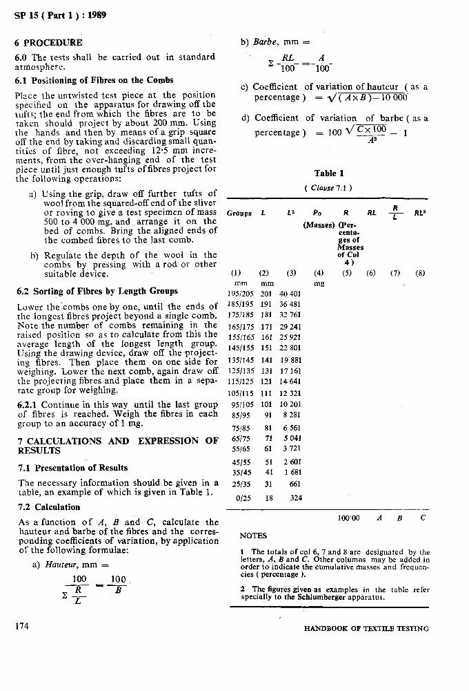
SP 15 ( Part 1) : 1989
6 PROCEDURE
6.0 The tests shall be carried out in standard atmosphere. 6.1 Positioning of Fibres on the Combs
Place the untwisted test piece at the position specified on the apparatus for drawing off the tufts; the end from which the fibres are to be taken should project by about 200 mm. Using the hands and then by means of a grip square off the end by taking and discarding small quan- tities of fibre, not exceeding 12.5 mm incre- ments, from the over-hanging end of the test piece until just enough tufts offibres project for the following operations:
a) Using the arip. draw off further tufts of woorfromthe’squared-off end of the sliver or roving to give a test specimen of mass 500 to 4 000 mg, and arrange it on the bed of combs. Bring the aligned ends of the combed fibres to the last comb.
Regulate the depth of the wool in the combs by pressing with a rod or other suitable device.
6.2 Sorting of Fibres by Length Groups
Lower the’combs one by one, until the ends of the longest fibres project beyond a single comb. pljote the number of combs remaining in the raised position so as to calculate from this the average length of the longest length group. Using the drawing device, draw off the project- ing fibres. Then place them on one side for weighing. Lower the next comb, again draw off the projicting fibres and place them in a sepa- rate group for weighing.
6.2.1 Continue in this way until the last group of fibres is reached. Weigh the fibres in each group to an accuracy of 1 mg.
7 CALCULATIONS AND EXPRESSION OF RESULTS
7.1 Presentation of Results
The necessary information should be given in a table, an example of which is given in Table 1.
7.2 Calculation
As a function of A, B and C, calculate the hauteur and barbe of the fibres and the corres- ponding coefficients of variation, by application of the following formulae:
a) Huuteur, mm =
100 100 --- z --- B
b) Barbe, mm =
RL A z -10s =-1oo-
c) Coefficient of variation of hauteur ( as a percentage ) = 2/(_4xB)-10000
d) Coefficient of variation of barbe ( as a
percentage ) = 100 d sA!?!? - 1
Table 1
( Clause 7.1 )
R Groups L L’J PO R RL r RL’
(Masses) (Per- centa. ges of Masses of co1
4) (1) (2) (3) (4) (5) (6) (7) (8) mm mm mg
1951205 201 40 401 185/195 191 36481 175/185 581 32 761
165/175 171 29 241 1551165 161 25921 145/155 151 22801
135/145 141 19 881 125/135 131 17 161 115/125 121 14641
105/115 111 12 321 951105 101 10 201 85/95 91 8 281
75/85 81 6 561 65175 71 5 041 55/65 61 3 721
45155 51 2601 35145 41 1 681
25135 31 661
O/25 18 324
100’00 A B c
NOTES
1 The totals of co1 6, 7 and 8 are designated by the letters, 4, B and C. Other columns may be added in order to indicate the cumulative masses and frequen- cies ( percentage ).
2 The figures given as examples in the table refer specially to the Schlumberger apparatus.
174 HANDBOOK OF TEXTILE TESTING

SPlS(Part1):1989
8 REPORT
8.1 The report shall include the following infor- mation:
a> b) C>
Type of material tested,
Type of apparatus used, and
Fibre length:
1) Hauteur, mm;
2) Barbe, mm;
3) Coefficient of variation of hauteur, percent; and
4) Coefficient of variation of barbe, percent.
9 ERROR OF THE METHOD ( REPRODUCI- BILITY OF METHOD )
9.1 Tests on six slivers of wool fibres, repeated three times, by six different laboratories gave
the results as given below: Error of Method
(see Note)
Hauteur Barbe Coefficient of
variation of hauteur
Coefficient of variation of barbe
O-86 mm O-70 mm 0.96 percent
O-63 percent
Maximum Interval of
Measurement, Percent
4.3
3.2
7.3
5.2
NOTE - The error of the method is defined as follows:
a) each lot measured obtains, in each laboratory, a mean value;
b) the means of the six laboratories make it possible to calculate an inter-laboratory mean which is distributed with a certain inter- laboratory standard deviation for each lot; and
c) the error of the method is the quadratic mean of these inter-laboratory standard deviations for all the lots.
ANNEX A
( Clause 4.1 )
SCHLUMBERGER COMB SORTER, TYPE M. A. E. FOR THE DETERMINATION OF WOOL FIBRE LENGTH*
A-l CHARACTERISTICS b)
A-l.1 The Schlumberger type M. A. E. comb sorter comprises a feed trough for the sliver which is driven to and fro, thus feeding the squared end of the sliver to a grip which lies above a bed of combs whose spacings determine the length groups of the fibres. This bed of combs may be moved laterally ( in a direction perpendicular to that of the fibres in the feed trough ), while the combs themselves can be lowered successively in a similar manner to a gill box used in spinning. A drawing-off system consisting of two endless leather belts is located at the front edge of the bed of combs and a circular brush collects the fibres drawn off.
cl
A-2 PROCEDURE
A-2.1 Arrangement of Wool on Combs
A-l.2 The sequence of operations carried out semi-automatically is as follows:
a) Movement of the feed trough towards the grip, thus taking successive draws of fibres of which the gripped ends are aligned,
A-2.1.1 Place the sliver in the feed trough of the comb sorter, projecting 2Oq mm towards the grip. The part of the sliver in the feed trough is under very slight tension.
A-2.1.2 Square off the sliver, first of all by hand up to approximately 10 mm from the comb being fed and then by twenty draws by means of the grip, forming a length of 20 x 4 mm=80 mm of sliver ( with the comb sorter operating and the comb bed removed ).
*The information ‘given on this apparatus is not intended to favour its use or to give a preference to the use of this apparatus.
PART 1, SECTION D/15 ,’
Deposition of tufts drawn, over the whole width of the bed of combs which moves laterally each time the feed trough moves. The aligned ends of the fibres are placed on the last comb.
Removal of the fibres projecting beyond each comb by means of a drawing-off system during the lateral movement of the bed of combs, starting with the long- est fibres.
175

SP 15 ( Part 1) : 1989
A-2.1.3 Verify that all the combs are at the same level, except for the last which should remain below the others and which will be raised later.
A-2.1.4 The combs are then covered with the wool automatically over the whole Iength of movement of the carriage. When this operation is completed, the last comb is raised to the level of the others.
A-2.1.5 Regulate the depth of wool in each spacing by pressing it down slightly with the rod designed for this purpose ( a rod curved at both ends ) and starting with the last spacing, that is. that of the shorter fibres. Carry out the operation a second time.
A-2.1.6 Place the retaining rod ( not the ends ) in the next to last space.
A-2.2 Length Sorting by Means Sorter
A-2.2.1 The comb bed comprises consecutive spacing of 10 mm.
of the Comb
a series of a
curved at
A-2.2.2 Depress the tist combs until the long- est fibres have their ends projecting beyond a single comb. It is essential here to evaluate correctly the first mean of the group under con- sideration. For this purpose, the number of remaining combs is taken as n, and the mean length of the group is taken as 10 ( p1 + 1 ), expressed in millimetres. The value is justified empirically. Thus the number of groups in existence can be seen.
A-2.2.3 The fibres are collected on the brush in the usual way by moving the carriage complete- ly in both directions for each space of 10 mm. These samplings per group are weighed sepa- rately on a balance giving an accuracy of 1 mg.
A-2.2.4 The last group to be taken should be specified. The next to last sampling is done mechanically with the two drawing off belts; it covers the groups of fibres projecting beyond the last three combs ( group with a mean length of 31 mm ). The antepenultimate comb is then lowered. The last sampling is done by hand on the fibres remaining at that point on the last two combs. This group has a mean length of 18 mm.
176 HANDBOBK OF TWTILB TESTING
SP 15 ( Part 1 ) : 1989
STAPLE LENGTH OF GREASY WOOL
( Source
I SCOPE
1.1 This standard prescribes a method for determina .tion of staple length of greasy ( clip- ped), pulled or limed wool.
2 APPARATUS
2.1 Velvet Board
of adequate and convenient size, such as 50 cmB; covered with velvet of black colour or any other colour in contrast with that of the wool.
2.2 Scale
graduated in centimetres and millimetres.
3 PREPARATION OF TEST SPECIMEN
3.1 The diameter of the staple shall be about 10 mm, if larger, it shall be reduced to this size.
4 PROCEDURE
4.1 Place the scale on the velvet board along the length of the board. Take a staple and place it along the scale on the velvet board. Gently straighten the staple if it is in a bent state. Remove the scale without disturbing the staple on the board and carefully adjust the zero mark
IS 6653 : 1972 )
of the scale with the base of the staple. Read the length of the staple to the nearest 5 mm. In case the staple does not have a clearly defined tip, that is, if it has tapering tip, take the read- ing from the base of the staple to the point on the tapering tip where the majority of the fibres end.
4.2 Similarly measure other test specimens. Test at least 100 test specimens.
5 CALCULATIONS
5.1 Calculate the average staple length from the individual measurements obtained as in 4.1 and 4.2 correct to 1 mm.
5.2 If required, calculate the standard deviation and coefficient of variation.
6 REPORT
6.1 The report shall include the following infor- mation:
a) Average staple length, and b) Number of observasions made.
FART 1, SECT& D/16 177

As in the Original Standard, this Page is Intentionally Left Blank

SP 15 ( Part 1 ) : 1989
CRIMP IN WOOL
( Source : IS 6124 : 1971)
The ‘waves’ or ‘curls’ present in wool fibre are , called ‘crimp’. Uniformity and abundance of
crimp are the indices of good quality wool. Usually the crimp is assessed either by counting the number of ‘waves’ or ‘curls’ present in the fibre and expressing it as the number of ‘waves’ or ‘curls’ per unit length or by measuring the difference in length of fibre between its unstret- ched and stretched condition and expressing it as a percentage of the fibre length in the
unstretched condition. Because the Indian wools do not possess well defined ‘waves’ or ‘curls’, this method is based on the later principle. The assessment of crimp, in wool fibre, is generally helpful to the sheep-breeder to judge the effects of pasture and cross-breeding on the quality of wool. Also the evaluation of crimp in wool fibre is essential for the purpose of grading wool on a rational and scientific basis.
1 SCOPE
1.1 This standard prescribes a method for deter- mination of crimp in wool fibres obtained from the bales, bags, heaps or fleece.
2 PREPARATION OF TEST SAMPLES
2.1 The gross sample drawn shall be thoroughly mixed. It shall then be spread out on a table in the form of an uniformly thick layer and divided in 16 zones. A tuft of about 100 to 200 g ( de- pending on the quality of wool ) shall be taken from each zone without disturbing the lock formation as far as possible.
2.2 Each tuft shall be divided into two approxi- mately equal parts, taking care to avoid break- ing of the fibres and one of the parts shall be discarded in each case. The other portion shall be again divided into two parts and one part of it again rejected. This process shall be repeated till about 60 fibres remain in each retained part. All the retained parts of fibre taken together shall constitute the test sample. The other parts which are to be discarded shall be collected together to constitute a duplicate test sample.
3 APPARATUS
3.1 For the purpose of this test, the following apparatus shall be used:
a) Velvet Board - of black or any other contrasting colour;
b) Flat Transparent Scale - graduated in centimetres and millimetres; and
c) Two Pairs of Forceps.
4 PROCEDURE
4.0 Tests shall be carried out in standard atmosphere.
PART 1, SECTION D/17
4.1 From the.conditioned sample draw at random at least 300 fibres. From these fibres take one fibre and lay it straight without stretching, on a velvet board. Place the scale over the fibre without disturbing it. Measure the unstretched length L correct to nearest millimetres, from end to end of the fibre. Take the same fibre and straighten it out by means of the pairs of for- ceps, taking care not to stretch it but merely to remove its crimp. Place it on the velvet board and measure straightened length L1 to nearest millimetre from end to end of the fibre as above.
4.2 Similarly determine the unstretched and stretched lengths of the remaining fibres, mak- ing a total of 300 observations.
5 CALCULATIONS
5.1 Calculate the crimp of each fibre by the following formula:
Crimp, percent = ____ L1 - L X 100 L
where
L1 = stretched length of fibre, and
L = unstretched length of the same fibre.
5.2 Calculate the mean crimp percentage, the standard deviation, the coefficient of variation and the standard error of the mean of all the observed values.
5.3 If the standard error of the mean so calcu- lated is less than 5 percent the mean crimp obtained as in 5.2 shall be reported and if the standard error of the mean SO calculated is equal to or more than 5 percent, determine the
179

SP 15 ( Part 1) : 1989
number of fibres required to make test at 5 per- cent level of significance, and test them follow-
a) ,Type of material,
ing the procedure given in 4.1. b) Crimp,
5.3.1 Calculate again, the mean crimp percen- c) Standard deviation, tage and report.
6 REPORT
6.1 The report shall include the following infor- mation:
d) Coefficient of variation,
e) Standard error of mean, and
f) Number of observations.
180 HANDBOOK OF TBXTILE TESTING
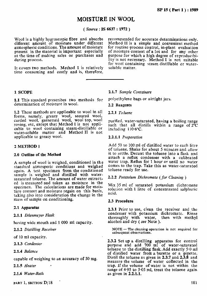
MOISTURE IN WOOL
SP 15 ( Part 1) : 1989
( Source : IS 6637 : 1972 )
Wool is a highly hygroscopic fibre and absorbs different amount of moisture under different
recommended for accurate determinations only.
atmospheric conditions. The amount of moisture Method II is a simple and convenient method
present in the material is important especially for routine process control, in-plant evaluation
at the time of making sales or purchases and of moisture content of a lot and for &y other purpose for which a high degree of remoducibi-
during process.
It covers two methods. Method I is time consuming and costly and is,
%tethgd I is noi suitable iity-is not necessary. for wool containing
relatively soluble matter. therefore,
steam distillable or water-
1 SCOPE
1.1 This standard prescribes t\ivo methods for determination of moisture in wool.
1.2 These methods are applicable to wool in all forms, namely, greasy wool, scoured wool, carded wool, garnetted wool, wool top, wool roving, etc, except that Method I is not appli- cable to wool containing steam-distillable or water-soluble matter and Method II is not appli’cable to greasy wool.
2 METHOD I
2.0 Outline of the Method
A sample of wool is weighed, conditioned in the standard atmosperic conditions and weighed again. A test specimen from the conditioned sample is weighed and distilled with water- saturated toluene. The amount of water extract- ed is measured and taken as moisture in the specimen. The calculations are made for mois- ture content and moisture regain on this basis, taking also into consideration the change in the mass of sample on conditioning.
2.1 Apparatus
2.1.1 Erlenmeyer Flask
having wide mouth and 1 000 ml capacity.
2.1.2 Distilling Receiver
of 10 ml capacity.
2.1.3 Condenser
2.1.4 Balance
capable of weighing to an accuracy of 50 mg.
2.1.5 Heater *
2.1.6 Water-Bath
PART 1, SECTION D/ 18 -
2.1.7 Sample Containers
polyethylene bags or airtight jars.
2.2 Reagents
2.2.1 Toluene
purified, water-saturated, having a boiling range such that all distills within a range of 2°C including 110.6%.
2.2.1.1 Preparation
Add 50 to 100ml of distilled water to each litre of toluene. Shake for about 5 minutes and allow it to settle. Decant the toluene into a flask and attach a reflux condenser with a calibrated water trap. Reflux for 1 hour or until no water comes to the trap. Take this as water-saturated toluene ready for use.
2.2.2 Potassium Dichromate (for Cleaning )
Mix 35 ml of saturated potassium dichromate solution with 1 litre of concentrated sulphuric acid.
2.3 Procedure
2.3.1 Prior to use, clean the receiver and the condenser with potassium dichromate. Rinse thoroughly with water, then with methyl alcohol and dry ( see Note ).
NOTE - The cleaning operation is not required for subsequent observations.
2.3.2 Set up a distilling apparatus for control purpose and add 700 ml of water-saturated toluene to the distilling flask. Add exactly 5.0 ml of distilled water from a burette or a pipette. Distil the toluene as given in 2.3.7 and 2.3.8 and measure the volume of water collected in the trap. If the volume of water is not within the range of 4.95 to 5.05 ml, treat the toluene again as given in 2.2.1.1.
181

k. -_ _-_-...
SP15(Partl): 1989
2.3.3 Draw a test sample and put it immediately in the sampling container and seal it. Deter- mine the mass of the container with sample and find out the net mass (MI) by deducting the tare from the total mass.
2.3.4 Condition the sample and determine its mass (Ma).
2.3.5 Take one test specimen from the condi- tioned sample, weighing about 50 to 70 g, and determine its mass (Ms) correct to 50 mg.
2.3.6 Transfer the test specimen immediately to the distilling flask and add 700 ml of toluene. Connect the flask, receiver and condenser and place the flask on the heater. Start the flow of cooling water through the condenser. Add more toluene through the top of the condenser until the receiver trap is full of toluene and it begins to flow to the flask.
2.3.7 Heat the toluene to boiling point and adjust the rate of distillation to 2 drops per second. When the rate of water accumulation becomes less than 0.1 ml per 15 minutes, increase the rate of distillation to 4 drops per second. Wash down the condenser by pouring toluene through the top of the condenser. Dislodge any visible drops of water with the help of a nylon brush saturated with toluene or with the help of a copper wire.
2.3.8 Continue distillation until there is no noticeable change in the level of meniscus for a period of 15 minutes. Separate the receiver containing water and toluene from the flask and condenser. Keep the receiver in the water- bath at room temperature for about 30 minutes and read the volume of water ( V) correct to 0.05 ml.,
-where
Ma = conditioned mass in g of the sample,
MI = original mass in g of the sample, V - volume in ml of the water collect-
ed, and MI = mass in g of the specimen taken.
NOTE - For calculation purpose, 1 ml of water = 1 g.
2.4.2 Calculate the average moisture content and average moisture regain of all the test specimens correct to one place of decimal.
2.4.3 For interconversion of moisture regain and moisture content values, the following equations may be used:
a) R - c
100 - c x loo R
b)c= lOO+R x 100
where
R = moisture regain, and C = moisture content.
3 METHOD II
3.0 Outline of the Method
A specimen of wool is weighed and then dried to constant mass in an oven at 105’C. The loss in mass of the specimen is taken as the loss of moisture and then calculations are made for moisture regain and moisture content on this basis.
3.1 Apparatus
2.3.9 Similarly test at least 6 more test speci- 3*1*1 Drying Oven mens. preferably of ventilated type, capable of main-
2.4 Calculations taining an inside temperature of 105 to 110°C and preferably fitted with weighing balance
2.4.1 Calculate the moisture content and mois- capable of weighing to an accuracy of 50 mg.
ture regain by the following formulae: 3.1.2 Specimen Containers
a) Moisture content, percent of perforated metal if the weighing is to be carried out inside the drying oven, or capable
= [S; (& - 1) + l] x 100 of being sealed if the specimen is to be cooled in a desiccator before weighing.
b) Mositure regain, percent 3.1.3 Sample Containers
polyethylene bags or airtight jars.
=cM, clM1 ;s ) - !jx loo 3.1.4 Balance .
capable of weighing to an accuracy of 1 mg.
182 HANDBOOK OF TEXTILB TESTING
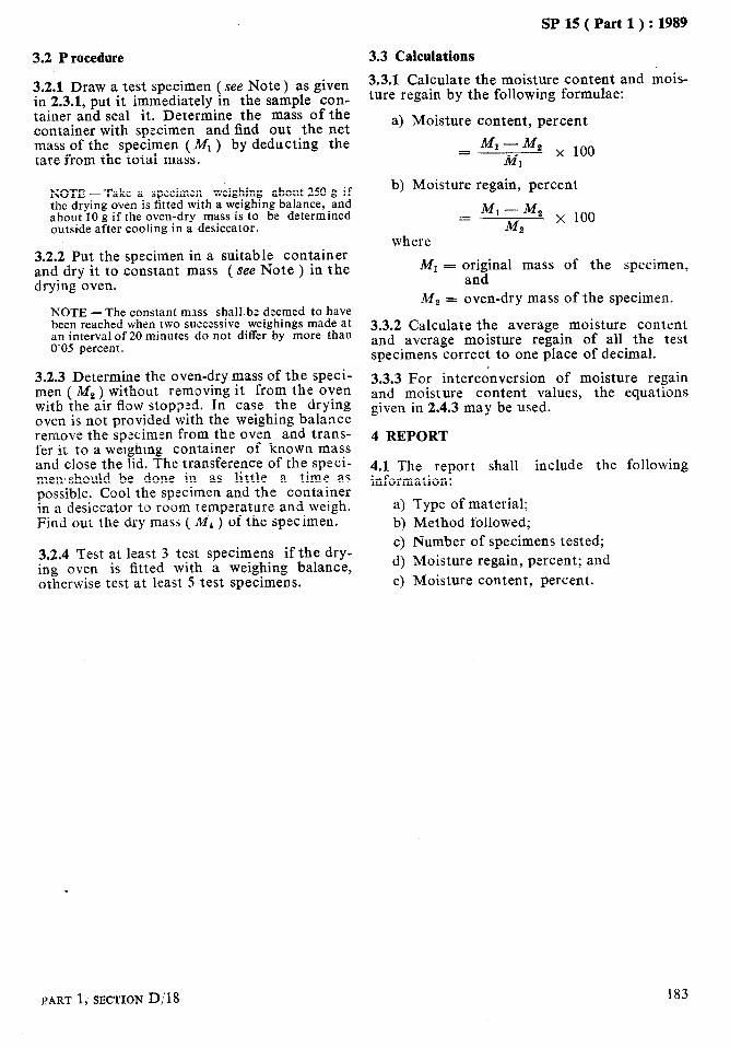
SP 15 ( Part 1) : 1989
3.2 P rocedure
3.2.1 Draw a test specimen (see Note) as given in 2.3.1, put it immediately in the sample con- tainer and seal it. Determine the mass of the container with specimen and find out the net mass of the specimen (Mr ) by deducting the tare from the total mass.
NOTE - Take a specimen weighing about 250 g if the drying oven is fitted with a weighing balance, and about 10 g if the oven-dry mass is to be determined outside after cooling in a desiccator.
3.2.2 Put the specimen in a suitable container and dry it to constant mass ( see Note ) in the drying oven.
NOTE -The constant mass shalLbe deemed to have been reached when two successive weighings made at an interval of 20 minutes do not differ by more than 0’05 percent.
3.2.3 Determine the oven-dry mass of the speci- men ( M, ) without removing it from the oven with the air flow stopped. In case the drying oven is not provided with the weighing balance remove the specimen from the oven and trans- fer it to a weighing container of known mass and close the lid. The transference of the speci- men,should be done in as little a time as possible. Cool the specimen and the container in a desiccator to room temperature and weigh. Find out the dry mass ( IvI1 ) of the specimen.
3.2.4 Test at least 3 test specimens if the dry- ing oven is fitted with a weighing balance, otherwise test at least 5 test specimens.
3.3 Calculations
3.3.1 Calculate the moisture content and mois- ture regain by the following formulae:
a) Moisture content, percent
= M1-M2 x 100 MI
b) Moisture regain, percent
= M1-M2 x 100 M!J
where
M, = original mass of the specimen, and
M2 = oven-dry mass of the specimen.
3.3.2 Calculate the average moisture content and average moisture regain of all the test specimens correct to one place of decimal.
3.3.3 For interconversion of moisture regain and moisture content values, the equations given in 2.4.3 may be used.
4 REPORT
4.1 The report shall include the following information:
4 Type of material;
b) Method followed;
4 Number of specimens tested;
4 Moisture regain, percent; and
4 Moisture content, percent.
PART 1, SECTION D(18 183

As in the Original Standard, this Page is Intentionally Left Blank
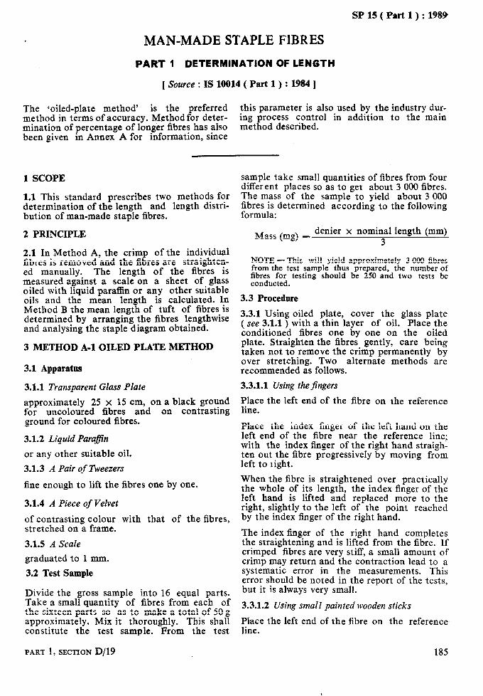
SP 15 ( Part 1) : 1989
MAN-MADE STAPLE FlBRES
PART 1 DETERMINATION OF LENGTH
[ Source : IS 10014 (. Part 1) : 1984 ]
The ‘oiled-plate method’ is the preferred this parameter is also used by the industry dur- method in terms of accuracy. Method for deter- ing process control in addition to the main mination of percentage of longer fibres has also method described. been given in Annex A for information, since
1 SCOPE
1.1 This standard prescribes two methods for determination of the length and length distri- bution of man-made staple fibres.
2 PRINCIPLE
2.1 In Method A, the crimp of the individual fibres is removed and the fibres are straighten- ed manually. The length of the fibres is measured against a scale on a sheet of glass oiled with liquid paraffin or any other suitable oils and the mean length is calculated. In Method B the mean length of tuft of fibres is determined by arranging the fibres lengthwise and analysing the staple diagram obtained.
3 METHOD A-l OILED PLATE METHOD
3.1 Apparatus
3.1.1 Transparent Glass Plate
approximately 25 x 15 cm, on a black ground for uncoloured fibres and on contrasting ground for coloured fibres.
3.1.2 Liquid ParaBn
or any other suitable oil.
3.1.3 A Pair of Tweezers
fine enough to lift the fibres one by one.
3.1.4 A Piece of Velvet
of contrasting colour with that of the fibres, stretched on a frame.
3.1.5 A Scale
graduated to 1 mm.
3.2 Test Sample
Divide the gross sample into 16 equal parts. Take a small quantity of fibres from each of the sixteen parts so as to make a total of 50 g approximately. Mix it thoroughly. This shall constitute the test sample. From the test
PART 1, SECTION D/19
sample take small quantities of fibres from four different places so as to get about 3 000 fibres. The mass of the sample to yield about 3 000 F:ibr;!s;; determined according to the following
Mass (mg) = denier x nominal length (mm) 3
NOTE -This will yield approximetely 3 000 fibres from the test sample thus prepared, the number of fibres for testing should be 250 and two tests be conducted.
3.3 Procedure
3.3.1 Using oiled plate, cover the glass plate ( see 3.1.1 ) with a thin layer of oil. Place the conditioned fibres one by one on the oiled plate. Straighten the fibres gently, care being taken not to remove the crimp permanently by over stretching. Two alternate methods are recommended as follows.
3.3.1.1 Using thejingers
Place the left end of the fibre on the reference line.
Place the index finger of the left hand on the left end of the fibre near the reference line; with the index finger of the right hand straigh- ten out the fibre progressively by moving from left to right.
When the fibre is straightened over practically the whole of its length, the index finger of the left hand is lifted and replaced more to the right, slightly to the left of the point reached by the index finger of the right hand.
The index finger of the right hand completes the straightening and is lifted from the fibre. If crimped fibres are very stiff, a small amount of crimp may return and the contraction lead to a systematic error in the measurements. This error should be noted in the report of the tests, but it is always very small.
3.3.1.2 Using small painted wooden sticks
Place the left end of the fibre on the reference line.
185
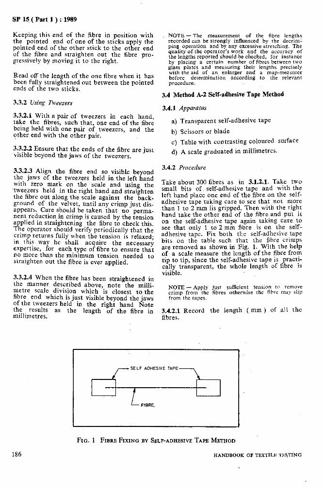
SP 15 ( Part 1) : ,1989
Keeping this end of the fibre in position with the pointed end of one of the sticks apply the pointed end of the other stick to the other end of the fibre and straighten out the fibre pro- gressively by moving it to the right.
Read off the length of the one fibre when it has been fully straightened out between the pointed ends of the two sticks.
3.3.2 Using Tweezers
3.3.2.1 With a pair of tweezers in each hand, take the fibres, such that, one end of the fibre being held with one pair of tweezers, and the other end with the other pair.
NOTE -The measurement of the fibre lengths recorded can be strongly influenced by the decriml ping operation and by any excessive stretching. The quality of the operator’s work and the accuracy of the lengths reported should be checked, for instance by placing a certain number of fibres between two glass plates and measuring their lengths precisely with the aid of an enlarger and a map-measurer before determination according to the relevant procedure.
3.4 Method A-2 Self-adhesive’ Tape Method
3.4.1 Apparatus
a) b)
Transparent self-adhesive tape
Scissors or blade
c> Table with contrasting coloured surface d) A scale graduated in millimetres. 3.3.2.2 Ensure that the ends of the fibre are just
visible beyond the jaws of the tweezers.
3.3.2.3 Align the fibre end so visible beyond the jaws of the tweezers held in the left hand with zero mark on the scale and using the tweezers held in the right hand and straighten the fibre out along the scale against the back- ground of the velvet, until any crimp just dis- appears. Care should be taken that no perma- nent reduction in crimp is caused by the tension applied in straightening the fibre to check this. The operator should verify periodically that the crimp returns fully when the tension is relaxed; in this way he shall acquire the necessary .expertise, for each type of fibre to ensure that no more than the minimum tension needed to straighten out the fibre is ever applied.
3.3.2.4 When the fibre has been straightened in the manner described above, note the milli- metre scale division which is closest to the fibre end which is just visible beyond the jaws of the tweezers held in the right hand Note the results as the length of the fibre in millimetres.
186
3.4.2 Procedure
Take about 300 fibres as in 3.1.2.1. Take two small bits of self-adhesive tape and with the left hand place one end of the fibre on the self- adhesive tape taking care to see that not more than 1 to 2 mm lis gripped. Then with the right hand take the other end of the fibre and put it on the self-adhesive tape again taking care to see that only 1 to 2 mm fibre is on the self- adhesive tape. Fix both the self-adhesive tape bits on the table such that the fibre crimps are removed as shown in Fig. 1. With the help of a scale measure the length of the fibre from tip to tip, since the self-adhesive tape is practi- cally transparent, the whole length of fibre is visible.
NOTE - Apply just sufficient tension to remove crimp from the fibres otherwise the fibre may slip from the tapes.
3.4.2.1 Record the length fibres.
SELF ADHESIVE TAPE
HANDBOOK
FIG. 1 FIBRE FIXING BY SELF-ADHESIVE TAPE METHOD
( mm ) of al! the
OF TEXTILE TESTING

3.5 Calculations
3.5.1 Mean Length, Standard Deviation and Coefficient of Variation
Group the individual length values in classes with class interval of 1 mm for a nominal length less than 45 mm, 2 mm for nominal length between 46 and 80 mm, and 5 mm for a nominal length above 80 mm. The middle point of the class interval, denoted by ( Li ) shall be taken to be the length of each fibres in that class. Let ni denote the number of fibres in the 1st class. The mean fibre length, standard deviation and- coefficient of variation shall be calculated by the following:
I k
1
I c 4 Li I i=l
Meanlength( 1 k i
i 1 ni I
I c 1 i-l 1
where k is number of classes.
21
k
c ni ( L&-L )”
Standard deviation i=l (a,)=
1 i n1 I : - 1
1 iZZ l 1
Coefficient of variation ( CV ) percent
X (
-$- x 100 >
3.5.2 Modal Length
Find out the class interval for which the number of fibres ni is maximum. The middle point of this class interval shall be taken as the modal length.
SP 15 ( Part 1) : 1989
3.5.3 Carry out two tests according to 3.3 and calculate parameters as per 3.4 for these tests. Determine average values of each parameters.
3.6 Report
3.6.1 The report shall include the following information:
4
b)
c)
4
Mean length ( mm j rounded off to one decimal p&e, ’
Standard deviation rounded off to two decimal places, Coefficient of variation rounded off to two decimal places, and Modal length rounded off to one decimal place.
4 METHOD B ARRAY METHOD
4.1 Apparatus
4.1.1 Sample Fibre Sorter and Accessories
4.1.2 Velvet Plus
4.1.3 Pair of Tweezers
4.2 Test Specimen
Take the specimen of about 200 to 500 mg depending on the denier.
4.3 Procedure
Weigh the specimen accurately and parallelize with a metal comb. Prepare the fibre array diagram of approximately 25 cm width with comb sorter as shown in Fig. 2.
4.4 Calculation
4.4.1 Method 1 - Staple Diagram Method
Divide the staple diagram prepared by the above procedure into 50 fibr e length groups, and mea- sure the fibre lengths on both the boundary
I J
VISCOSE STAPLE FIBRE (40 mm < 3% SHORT FIBRES )
FIG. 2 TYPICAL FIBRE ARRAY DIAGRAM
PART 1,SECTION D/19 187
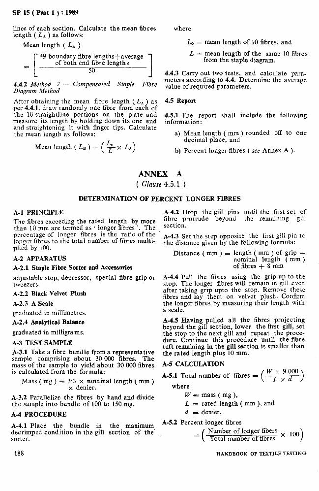
SP 15 ( Part 1) : 1989
lines of each section. Calculate the mean 6bres length ( LA ) as follows:
Mean length ( LA )
[
49 boundary fibre lengthsfaverage of both end fibre lengths =
50 I
44.2 Method 2 - Compensated Staple Fibre Diagram Method
After obtaining the mean fibre length ( L, ) as per 44.1, draw randomly one fibre from each of the 10 straightline portions on the plate and measure its length by holding down its one end and straightening it with finger tips. Calculate the mean length as follows:
Mean length ( LB ) = ( ce x LA)
where
LO = mean length of 10 fibres, and
L = mean length of the same 10 fibres from the staple diagram.
4.4.3 Carry out two tests, and calculate para- meters according to 4.4. Determine the average value of required parameters.
4.5 Report
4.5.1 The report shall include the following information:
a) Mean length ( mm ) rounded off to one decimal place, and
b) Percent longer fibres ( see Annex A ).
ANNEX A ( Clause 4.5.1 >
DETERMINATION OF PERCENT LONGER FIBRES
A-I PRINCIPLE The fibres exceeding the rated length by more than 10 mm are termed as ‘ longer fibres ‘. The percentage of longer fibres is the ratio of the longer fibres to the total number of fibres multi- plied by 100.
A-2 APPARATUS A-2.1 Staple Fibre Sorter and Accessories
adjustable stop, depressor, special fibre grip or tweezers. A-2.2 Black Velvet Plush
A-2.3 A Scale graduated in millimetres. A-2.4 Analytical Balance
graduated in milligrams.
A-3 TEST SAMPLE A-3.1 Take a fibre bundle from a representative sample comprising about 30 000 fibres. The mass of the sample to yield about 30 000 fibres is calculated from the formula:
Mass(mg)= 3;3d;ngminal length ( mm ) .
A-3.2 Parallelize the fibres by hand and divide the sample into bundle of 100 to 150 mg.
A-4.2 Drop the gill pins until the first set of fibre protrude beyond the remaining gill section.
A-4.3 Set the step opposite the first gill pin to the distance given by the following formula:
Distance ( mm ) = length ( mm ) of grip + nominal length ( mm ) of fibres + 8 mm
A-4.4 Pull the fibres using the grip up to the stop. The longer fibres will remain in gill even after taking grip upto the stop. Remove these fibres and lay them on velvet plush. Confirm the longer fibres by measuring their length with a scale.
A-4.5 Having pulled all the fibres projecting beyond the gill section, lower the first gill, set the stop to the next gill and repeat the proce- dure. Continue this procedure until the fibre tuft remaining in the gill section is smaller than the rated length plus 10 mm.
A-5 CALCULATION
A-5.1 Total number of fibres = ( w x 9 000
Lxd > where
W = mass ( mg ), L = rated length ( mm ), and
A-4 PROCEDURE d - denier.
A-4.1 Place the bundle in the maximum A-5.2 Percent longer fibres
decrimped condition in the gill section of the’ I Number of longer fibers x loo sorter. Total number of fibres >
188 HANDBOOK OF TEXTILE TESTING

SP 15 ( Part 1) : 1989
MAN-MADE STAPLE FIBRES
PART 2 DETERMINATION OF LINEAR DENSITY
\ Source : IS 10014 ( Part 2 ) : 19811
1 SCOPE
1.1 This prescribes two methods for the deter- mination of average linear density of staple fibres. One method applies to fibres cut to a definite length and the other to whole fibres. This standard is not suitable for blends having different, nominal linear densities.
1.2 The methods may not give sufficiently accurate estimation of the linear density if the fibres are highly crimped.
2 PRINCIPLE
2.1 In both the methods, the length and mass of conditioned fibres are determined and the linear density is calculated from these values.
3 METHOD A (APPLICABLE TO CUT FIBRE BUNDLES )
3.1 Apparatus
3.1.1 Means for cutting a fibre bundle to an accurately known length.
NOTE - A convenient cutter contists of two sharp razor blades set parallel 20 mm apart in a holder.
3.1.2 Forceps-
for collecting the fibres.
3.1.3 Black Velvet Pad
3.1.4 Microbalance
suitable for weighing an accuracy of 0*005 mg.
3.1.5 A Steel Comb
having about 12 needles per centimetre.
3.1.6 Magnifying Glass
3.1.1 Glass Slide
3.2 Procedure
Select five tufts from a well spread out sample. Parallelize them thoroughly by gently combing both sides alternately. Clamp one end of a tuft and again parallelize them. Apply a suitable tension sufficient to remove the crimp in the fibres and grip the free end of the tuft. Ensure that all the fibres are caught at both the grips.
PART ,I, SECTION D/20
Using the cutter cut the middle portion. Collect the fibres and place on the velvet pad. ( see Note 1 ). Cover it with a glass slide. Collect 100 fibres and weigh in the micro- balance to an accuracy of 0005 mg. Repeat the procedure with the remaininb four tufts.
NOTES
1 The operation of combing of tufts, parallelization, cutting, etc, are done prior to preconditioning and conditionining of the test specimens; this will ensure that the fibres are not handled after conditioning. 2 A magnifying glass will help to avoid miscounting the fibres while collecting. 3 Cutting should be carried out in such a way that there is no lateral movement of the fibres while cutt- ing. This can be ensured by placing the fibre bundle under tension over a rigid base with the fibres lying straight on the base. 4 Tension to be applied is texl2 or denier/l8 which may be obtained by preliminary test.
3.3 Calculation
3.3.1 Calculate the linear density millitex or denier using the following equation:
mtex ( millitex ) = -+ x loa
OR
d ( denier) -+JX9000
where
m - mass, in mg, of the bundle of fibres,
n = i;rber of fibres ( 50 in this case ),
1 = cut length, in mm.
3.3.2 Calculate the linear density of the remain- ing four tufts.
3.3.3 Calculate the average of the five readings and report the average value and the coefficient of variation.
NOTE - The coefficient of variation value shall be calculated as follows:
Coefficient of variation (CV), percent = q X 100
where
ad = d: + d; +d;-v
4
189

SPlS(Part1): 1989
4 METHOD B ( APPLICAB&E TO WHOLE FIBRES )
4.1 Apparatus
4.1.1 Velvet Pad
4.1.2 Forceps
4.1.3 A Fine Steel Comb
4.1.4 A Scale
graduated to 0.5 mm.
4.1.5 Microbbl&fnce
suitable for weighing to an accuracy of 0.005 mg.
4.1.6 Glass Plate
4.1.7 Liquid Para@% or Petroleum Jelly
4.1.8 Magnifying Glass
4.1.9 Glass Slide
4.2 Procedure
4.2.1 Select five tufts at random, from a well spread out sample. Parallelize them well by gently combing both sides. Place them on the velvet pad,( see Note 1 under 3.2 ). Cover the tuft with a glass slide.
4.2.2 Pick out one fibre after another and thus collect fibres from parallelized tufi. Weigh in the microbalance to an accuracy of 0.005 mg. Record the mass. Place them on the clean portion of the velvet pad. Pickout one fibre and place it on the glass plate smeared with paraffin or petroleum jelly. Gently straighten the fibre using the forefingers to remove all the crimp.
190
Measure ‘the length of the straightened fibre to an accuracy cf 0.5 mm. Measure all the remain- ing 49 fibres and record the length. Repeat the above procedure of weighing and measuring length for all the remaining 4 tufts.
4.3 Calculation
4.3.1 Calculate the linear density millitex or denier as follows:
m mtex ( millitex ) = 5. x I x 106
OR
d ( denier ) = 5OmxI xgo00
where m = mass, in mg, of 50 fibres, and 1 = is the length, in mm, of a fibre.
4.3.2 Calculate the linear density of the remaining 4 tufts.
4.3.3 Calculate the average of the 5 values and report the average value and coefficient of variation value.
NOTE - The coefficient of variation shall be calcula- . ted bjl using formula given in Note under 3.3.3.
5 REPORT
5.1 The test report shall include the following:
a) The method used; b) The cut length ( in the case of method
A); c) The average linear density in ‘millitex or
denier; and d) The coefficient of variation value.
. .
HANDBOOK OF TEXTILE TESTING
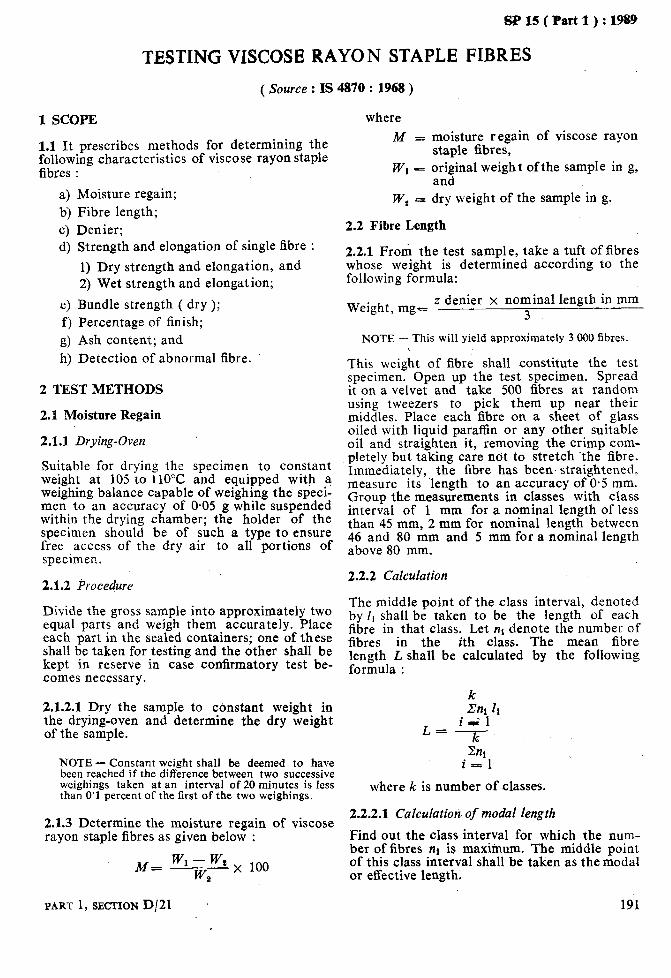
sP15(Part1):1989
TESTING VISCOSE RAYON STAPLE FIBRES
( Source : IS 4870 : 1968 )
1 SCOPE
1.1 It prescribes methods for determining the following characteristics of viscose rayon staple fibres :
4 b> 4 d)
e) f ) g> h)
Moisture regain; Fibre length; Denier; Strength and elongation of single fibre :
1) Dry strength and elongation, and 2) Wet strength and elongation;
Bundle strength ( dry ); Percentage of finish; Ash content; and Detection of abnormal fibre.
2 TEST METHODS
2.1 Moisture Regain
2.1.1 Drying-Oven ’
Suitable for drying the specimen to constant weight at 105 to ilOX! and equipped with a weighing balance capable of weighing the speci- men to an accuracy of 0.05 g while suspended within the drying chamber; the holder of the specimen should be of such a type to ensure free access of the dry air to all portions of specimen.
2.1.2 Procedure
Divide the gross sample into approximately two equal parts and weigh them accurately. Place each part in the sealed containers; one of these shall be taken for testing and the other shall be kept in reserve in case confirmatory test be- comes necessary.
2.1.2.1 Dry the sample to constant weight in the drying-oven and determine the dry weight of the sample.
NOTE - Constant weight shall be deemed to have been reached if the difference between two successive weighings taken at an interval of 20 minutes is less than 0’1 percent of the first of the two weighings.
2.1.3 Determine the moisture regain of viscose rayon staple fibres as given below :
M= w w1 - wa x 100 a
PART 1, SECTION D/21
where M -_ moisture regain of viscose rayon
staple fibres, WI - original weight of the sample in g,
and W, = dry weight of the sample in g.
2.2 Fibre Length
2.2.1 From the test sample, take a tuft of fibres whose weight is determined according to the following formula:
Weight, mg- z denier x nominal length in mm 3
NOTE - This will yield approximately 3 000 fibres.
This weight of fibre shall constitute the test
specimen. Open up the test specimen. Spread it on a velvet and take 500 fibres at random using tweezers to pick them up near their middles. Place each fibre on a sheet of glass oiled with liquid paraffin or any other suitable oil and straighten it, removing the crimp com- pletely but taking care not to stretch the fibre. Immediately, the fibre has been. straightened, measure its ‘length to an accuracy of 0.5 mm. Group the measurements in classes with class interval of 1 mm for a nominal length of less than 45 mm, 2 mm for nominal length between 46 and 80 mm and 5 mm for a nominal length above 80 mm.
2.2.2 Calculation
The middle point of the class interval, denoted by I, shall be taken to be the length of each fibre in that class. Let nt denote the number of fibres in the ith class. The mean fibre E$$l,L shall be calculated by the following
k .m 4
L_ i&l -- k
Zn1 i = 1
where k is number of classes.
2.2.2.1 Calculation’ of modal length
Find out the class interval for which the num- ber of fibres nl is maximum. The middle point of this class interval shall be taken as the modal or effective length.
191

SP 15 ( Part 1) : 1989
2.3 Denier
2.3.1 Take 10 tufts each of a few milligrams from the test sample. Parallelize and carefully clean by hand each tuft of fibre. Straighten the fibres by gently combing the fibres in oppo- site directions by turn. Holding one end of the tuft, apply a tension [ equivalent to tex/2 ( or denier/l8 ) ] to remove the crimp. Cut an accu- rately known length from the middle taking care that no fibre ends protrude anywhere except at the cut ends of the tuft. Place 10 cut bundles on a dark coloured surface and fix them loosely. Draw the fibres from each of the 10 prepared bundles so that all the fibres drawn and put together form a bundle of 50 fibres. Prepare, 10 such bundles in this way. Condition and weigh these bundles separately and deter- mine the mean weight weighing to an accuracy of O-5 ,g for a 1 cm cut length and 1.0 pg for a 2 cm cut length.
2.3.2 Determine the denier of the viscose rayon staple fibre as given below :
D’= q x 180
where \
D = denier of viscose rayon staple fibre,
T - mean tenacity of single fibre; m - mean breaking load, in g, of the
single fibre; and d = denier.
2.4.2 Wet Strength and Elongation
2.4.2.1 Apparatus W = weight of 50 fibres in mg, and L -c bundle length in mm.
2.4 Single Fibre Strength and Elongation
2.4.1 Dry Strength and Elongation
The apparatus and other related details such as gauge length, recording accuracy of results, etc, shall be the same as for the dry strength, ( see 2.4.1.1 to 2.4.1.3 ).
2.4.2.2 Procedure 2.4.1.1 Apparatus
A constant-rate-of-load type machine shall pre- ferably be used for the test. Alternatively, a constant-rate-of-traverse or constant-rate-of- extension type machine may also be used. 2.4.1.2 The time of break shall be so adjusted that the specimen breaks after 20 f 2 seconds of the commencement of the test. Any test result in which the specimen breaks at the clamps or whose rupture occurs within 10 per- cent or above 90 percent of the scale of the apparatus shalt be discarded.
2.4.1.3 Accuracy of the “measurement of test results shall be as follows :
Follow the same procedure as in 2.4.1.4, except that the test shall be carried out with the fibre immersed in water. A convenient method to perform the test is to fix the dry fibre in the upper grip of the testing machine, immerse it in water, and then fix it in the lower grip. The fibre must remain immersed in water throughout the test but the water must not be al owed to reach the upper grip.
2.4.2.3 Calculation
Same as in 2.4.1.5.
Breaking load ( in g ) Extension ( in mm )
2.4.1.4 Procedure
1 percent O-1 mm
2.4.3 Ratio of Wet Strength to Dry Strength
2.4.3.1 The ratio of wet strength to dry strength shall be calculated by the following formula :
W R=-
D
Take sufficient number of conditioned single fibres such that at least 50 tests are made. Mount a single fibre in the testing machine keeping the distance between the clamps to 10 mm. Apply an initial tension on the fibre to
where R = ratio of wet strength to dry
strength, W = wet strength ( see 2.4.2.3 ), and D = dry strength ( see 2.4.1.5 ).
192 HANDEOOIi OF TEXTILE TESTING
remove the slack. ,The tension to be applied on the specimens shall be as follows :
d g l-5 or less 0.1 Above 1.5 up to 3 0.2 Above 3 up to 7 0.3 Above 7 0.5
Operate the machine until the specimen rup- tures. Record the breaking load in grams and the extension in millimetres. Carry out 49 more tests. Calculate the mean breaking load and elongation of the 50 fibres thus broken.
2.4.1.5 Calculation
Calculate the mean tenacity of the fibre in grams per denier as follows :
where

SP 15( Part 1):1989
2.5 Bundle Strength ( Dry )
The bundle strength of the fibres shall be deter- mined by the method prescribed for cotton fibres.
2.6 Percentage of Finish
2.6.1 Apparatus
2.6.1.1 Sqxhlet extractor
2.6.1.2 Conical flask
2.6.2 Reagents
2.6.2.0 Quality of reagents
Unless specified otherwise, pure chemicals shall be employed in tests and distilled water shall be used where the use of water or distilled water as a reagent is intended.
NOTE - ‘Pure chemicals’ shall mean chemicals that do not contain impurities which affect the test results.
2.6.2.1 Benzene alcohol mixture
1 : 1.
2.6.3 Procedure
2.6.3.1 Take about 10 g of fibres and weigh them accurately. Transfer the 6bres into a muslin bag which has previously been extracted with the solvent. Transfer the bag along with the fibres to the soxhlet extractor. Weigh the empty flask of the assembly. Introduce into the flask a quantity of benzene alcohol mixture equal to twice the volume of the soxhlet extrac- tor up to the level of the top of the syphon tube. Keep the assembly on a water-bath. Continue the extraction for 8 hours keeping rate of the syphon at 6 cycles per hour.
2.6.3.2 Take out the muslin bag along with the fibres from the extractor. Distil off the solvent. Ensure that no solvent vapour remains in the flask. Remove the flask and clean the outer surface. Dry it in a hot oven at a temperature of 150 to 110°C to constant weight for nearly 10 minutes. Cool the flask and weigh the con- tents to an accuracy of 0.1 mg ( W, ).
2.6.3.3 Determine separately the moisture content of the sample under test and from it calculate the dry weight of the test specimen (W%). 2.6.3.4 Calculate the percentage of finish by the following formula :
Fe +- x 100 2
where F = finish in percent, w, = weight of residue ( see 2.6.3.2 ), and WS = weight of dry fibres ( see 2.6.3.3 ).
2.7 Ash Content
2.7.1 Procedure
Take about 5 g of fibres and weigh accurately. Transfer these fibres to a tared silica dish. Heat it over a Bunsen burner. After the 6bres are carbonized, transfer them to a muffle furnace and keep them there (about 30 minutes ) at 7OO”C, until a white ash is obtained. Cool the dish and weigh accurately the contents.
2.7.2 Determine separately the moisture con- tent present in the sample under test and from it determine the dry weight of the test speci- men.
2.7.3 Calculate the ash content by the following formula:
A = -$- x 100 a
where
A = ash content, percent; WI c weight of residue ( see 2.7.1);
and W, = weight of dry sample ( see 2.7.2 ).
2.8 Detection of Abnormal Fibres and Other Matters
2.8.1 Weigh accurately 500 g of fibres from the gross sample. Examine them for any abnormal fibres and other matters and isolate them. Weigh the abnormal fibres and other matters so collec- ted. Express this weight as a percentage of the weight of fibre in the sample taken ( 500 g). This shall be the percentage of abnormal fibre and other matters in the sample. It is advisable to process the sample through a Shirley Analyser and then sort out the droppings by hand for abnormal fibres and other matters.
3 REPORT
3.1 The Report shall include the following in- formation :
a) Type of material tested; b) Moisture regain; c) Fibre length; d) Denier; e) Strength and elongation of single fibre :
1) Dry strength and elongation, and 2) Wet strength and elongation;
f) Bundle strength ( dry ); g) Percentage of finish; h) Ash content; and j) Abnormal fibre, percent.
PART 1, SECTION D/21 193

As in the Original Standard, this Page is Intentionally Left Blank
SP 15 ( Part 1) : 1989
UNCUT INDIAN JUTE, MESTA AND BIMLZ
( Source : IS 7032 : 1986 )
This is aimed at obtaining instrumental measures for characteristics of jute, MESTA and BIMLI
minimum of efforts and where scoring could be possible, have been selected after survey of the
fibres for the purpose of grading. To achieve this aim only those methods, which are simple
work done by research institutions, the publish-
and could be adopted by the graders with the ed literature and also keeping in view the type of instruments available with the industry.
PART 1, SECTION D/22 195

As in the Original Standard, this Page is Intentionally Left Blank
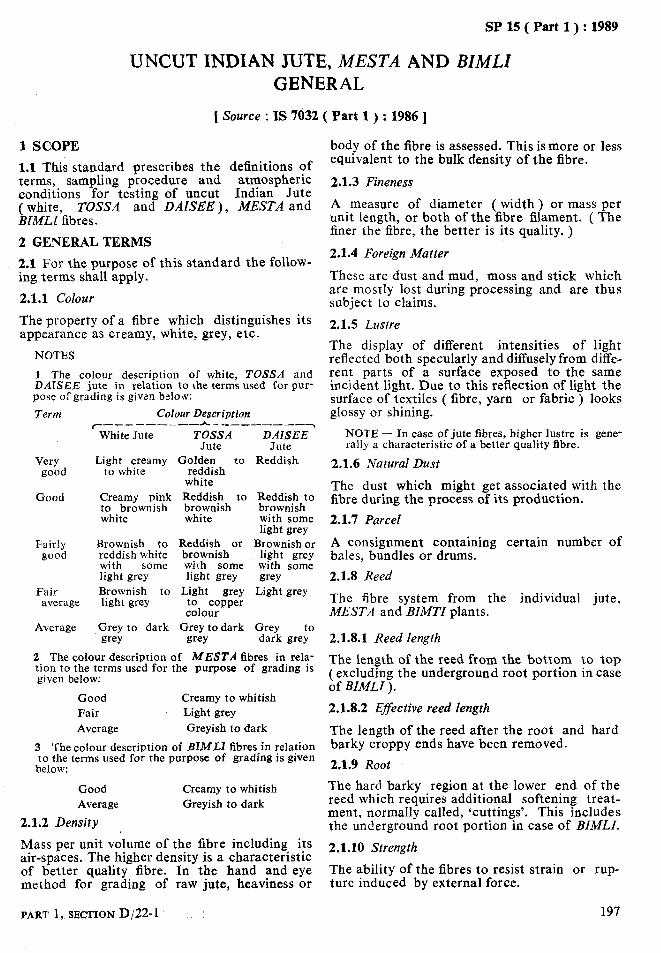
SP 15 ( Part 1) : 1989
UNCUT INDIAN JUTE, MISTA AND BIMLI GENERAL
1 Source : IS 7032 ( Part 1) : 1986 ]
1 SCOPE
1.1 This standard prescribes the definitions of terms, sampling procedure and atmospheric conditions for testing of uncut Indian Jute
$&%?fibres. TOSSA and DAlSEE ), MESTA and
2 GENERAL TERMS
2.1 For the purpose of this standard the follow- ing terms shall apply.
2.1.1 Colour
The property of a fibre which distinguishes its appearance as creamy, white, grey, etc.
NOTES
1 The colour description of white, TOSSA and DAISEE jute in relation to the terms used for pur- pose of grading is given below:
Term Colour Description r--------- * _ _________~
White Jute TOSSA DAISEE Jute Jute
Very Light creamy Golden to Reddish good to white reddish
white Good Creamy pink Reddish to Reddish to
to brownish brownish brownish white white with some
light grey Fairly Brownish to Reddish or Brownishor
good reddish white brownish light grey with some with some with some light grey light grey grey
Fair Brownish to Light grey Light grey average light grey to copper
colour Average Grey to dark Grey todark Grey
grey grey dark gre;
2 The colour description of MESTA fibres in rela- tion to the terms used for the purpose of grading is given below:
Good Creamy to whitish Fair Light grey Average Greyish to dark
3 The colour description of BIMLI fibres in relation to the terms used for the purpose of grading is given
below:
Good Average
2.1.2 Density
Creamy to whitish Greyish to dark
Mass per unit volume of the fibre including its air-spaces. The higher density is a characteristic of better quality fibre. In the hand and eye method for grading of raw jute, heaviness or
body of the fibre is assessed. This ismore or less equivalent to the bulk density of the fibre.
2.1.3 Fineness
A measure of diameter ( width) or mass per unit length, or both of the fibre filament. ( The finer the fibre, the better is its quality, )
2.1.4 Foreign Matter
These are dust and mud, moss and stick which are mostly lost during processing and are thus subject to claims.
2.1.5 Lustre
The display of different intensities of light reflected both specularly and diffusely from diffe- rent parts of a surface exposed to the same incident light. Due to this reflection of light the surface of textiles ( fibre, yarn or fabric ) looks glossy or shining.
NOTE - In case of jute fibres, higher lustre is gene- rally a characteristic of a better quality fibre.
2.1.6 Natural Dust
The dust which might get associated with the fibre during the process of its production.
2.1.7 Parcel
A consignment containing certain number of bales, bundles or drums.
2.1.8 Reed
The fibre system from the individual jute, MESTA and BIMTI plants.
2.1.8.1 Reed length
The length of the reed from the bottom to top (excluding the underground root portion in case of BIMLI ).
2.1.8.2 Effective reed length
The length of the reed after the root and hard barky crappy ends have been removed.
2.1.9 Root
The hard barky region at the lower end of the reed which requires additional softening treat- ment, normally called, ‘cuttings’. This includes the underground root portion in case of BIMLI.
2.1.10 Strength
The ability of the fibres to resist strain or rup- ture induced by external force.
PART 1, SBCTION D/22-1 197
SP 15 ( Part 1) : 1989
2.1.10.1 The strength aspect of the fibres is classified depending upon their tenacity.
NOTES
1 Tenacity is the breaking load of a material under test divided by .the linear density of the unstrained material, expressed as grams per tex.
2 Linear density is the mass per unit length; the quotient obtained by dividing the mass of fibre or yarn by its length. When the mass is expressed in grams and the length in kilometres, the resulting value, that is, the quotient, is expressed as tex.
2.2 Defects
a) Major - Entangled crappy end fibre, centre root, dazed and over-retted fibres, mossy fibre, runners, knots, entangled sticks and hunka.
b) Minor - Croppy fibre, weak crappy fibre, gummy fibre, loose sticks, specks, leaf and loose leaf.
2.2.1 Centre Root ( BUK CHHAL )
The hard barky region in the middle part of the reed which requires additional softening treat- ment.
2.2.2 Croppy Fibre
Fibre with, top ends rough and hard ( but not barky ) caused by careless retting.
2.2.2.1 Weak croppyfibre
Fibre which has become unusually weak over a length of about 30 cm at the top end.
2.2.2.2 Entangled crappy end$3re
Fibre with unusually entangled crappy end.
2.2.3 Dazed Fibre
Fibre which is weak in strength and dull in appearance, due to usually being stored in moist condition.
2.2.4 Gummy Fibre
Fibres held together by undissolved pectinous matter.
2.2.5 Hunka .
The very hard barky fibre running continuously from the lower end to almost the tip of the reed.
2.2.6 Knots
Stiff barky spots in the body of the reed which break the continuity of the fibres when opened.
2.2.1 Leaf and Loose Leaf
It is the dark grey leafy or paper like substance ( remnant of the skin of the plant ) appearing on the strand. Loose leaves are those that lie loosely on the fibre and are easily removable.
2.2.0 Mossy Fibre
A type of vegetation which sometimes gets attached to the plant. Its portions may remain on the fibre even after retting and washing. It can be separated by hand.
2.2.9 Over-Retted Fibre
Fibre which has lost its strength and brightness on decomposition due to prolonged retting.
2.2.10 Runners
Hard barky fibre running from the lower end to the middle region, more or less continuously.
2.2.11 Specks
Soft barky spots in the body where fibres can be separated with some effort without breaking their continuity, though they may remain as weak spots.
2.2.12 Sticks, Entangled Sticks and Loose Sticks
Sticks are remnants of woody part of jute, MESTA and BIMLI plant over which fibre sheath is formed. Entangled sticks are broken sticks which are linked with fibre mass and are not easily removable. Loose sticks are broken sticks easily removable by shaking.
198 HANDBOOK OF TEXTILE TESTING
SP 15 ( Part 1) : 1989
UNCUT INDIAN JUTE, MESZ’A AND BZMZ,Z REED LENGTH
[ Source : IS 7032 ( Part 2 ) : 1986 ]
1 SCOPE
1.1 This standard prescribes a method for the determination of reed length of jute, MESTA and BIMLI fibre strands.
2 EQUIPMENT
2.1 The following equipment are required:
a) A smooth platform or floor, b) Measuring tape, and c) A pair of scissors.
3 PROCEDURE
3.1 Reed Length
Lay the fibre strand on a smooth horizontal platform or floor. Remove any kinks or bends with minimum tension without unduly stretch- ing the fibre strand. Measure the length of the
strand from one end to the other with the help of a tape correct to 05 cm ( L ).
3.2 Effective Reed Length
Measure the length of the root ( Ll) and crappy end portion ( LI ) correct to 0.5 cm. Determine the effective reed length by the following formula:
Effective reed length = L - ( L1 + L, )
3.3 Repeat the test with the remaining test specimens and determine the average of all the values.
4 REPORT
4.1 The report shall include the following information:
a) Average reed length,
b) Average effective reed length, and c) Size of the sample ( strands ).
PART 1, SECTION D/22-2 199

As in the Original Standard, this Page is Intentionally Left Blank
SP 15 ( Part 1) : 1989
UNCUT INDIAN JUTE, MESTA AND BIMLZ ROOT CONTENT
[ Source : IS 7032 ( Part 3 ) : 1986 ]
1 SCOPE 3.3 Repeat the test with the remaining test
1.1 This standard prescribes a method for the specimens’ determination of root content of jute, MESTA and BIMLI fibre strands.
4 CALCULATIONS
2 EQUIPMENT
2.1 The following equipment are required:
a) Weighing balance, and b) A pair of scissors.
3 PROCEDURE
3.1 Take a test specimen consisting of full length reeds. Weigh it in a balance correct to 1 g(W1). 3.2 Cut off the bottom root portion frbm each individual strand so that the cut fibres do not contain any root. Weigh the root portion correct to 1 g ( W, ).
4.1 Calculate the root content of the individual test specimens as follows:
Root content W, = w x 100 1
4.2 Calculate the average of all the values obtained in 4.1.
5 REPORT
5.1 The report shall include the following information:
a) Average root content, percent; and b) Size of the sample ( strands ).
PART 1, SECTION D/22-3 201

As in the Original Standard, this Page is Intentionally Left Blank
SP 15 ( Part 1) : 1989
UNCUT INDIAN JUTE, MESTA AND BIJiLI DEFECTS
[Source : IS 7032 ( Part 4 ) : 1986 ]
1 SCOPE 4 CALCULATIONS
I.1 This standard prescribes a method for the 4.1 Calulate the percentage of centre-root, determination of defects ( centre root, crop- crop-end, runner and hunka of the individual end, runners and hunka ) in the jute, MESTA test specimens as folloWs: and BIMLI fibre strands.
2 EQUIPMENT ~
2.1 The following equipment are required:
a) Weighing balance, and b) A pair of scissors.
3 PROCEDURES
a) Centre-root, Pr = Wl 7 x 100
b) Crop-end, P, W2 = 7 x 100
c) Runner, P3 = E;- x 100
d) Hunka, P4 W, = TX 100
3.1 Take a test specimen consisting of full 4.2 Determine the percentage of total defects length reeds and determine its mass to an accuracy of 1 g ( W).
by adding P1, Pz, Ps and Pg.
3.2 Cut the centre-root and crop-end portions 4.3 Determine the average of all the values.
and keep them separately. Determine the mass 5 REPORT of the centre-root ( W, ) and crop-end ( W,) to an accuracy of 1 g. 5.1 The report shall include the following
information:
3.3 Separate out the runners from the cut fibres, if any, determine its mass to an accuracy Of18(W3)*
a) Average percentage of: 1) centre-root, 2) crop-end,
3.4 Remove the hunka from the cut fibres, and 3) runner, and determine its mass correct to 1 g ( W,). 4) hunka;
3.5 Repeat the test with the remaining test b) Average total defects: and specimens. c) Size of the sample ( strands ).
PART 1, SECTION D/22-4 203

As in the Original Standard, this Page is Intentionally Left Blank
SP 15 ( Part 1) : 1989
UNCUT INDIAN JUTE, MESTA AND BZMZJ FOREIGN MATTER
[ Source : IS 7032 ( Part 5 ) : 1986 ]
1 SCOPE
1.1 This standard prescribes a method for the determination of foreign matter ( dust, mud, moss and stick ) of the jute, MESTA and BIMLI fibre strands.
3.2 Repeat the test with the remaining test specimens.
4 CALCULATIONS
2 EQUIPMENT 4.1 Calculate the percentage of foreign matter of the individual test specimen as follows:
2.1 Weighing Balance
3 PROCEDURES Foreign matter, percent 0 WI - w, x I()()
Wl
3.1 Take a test specimen and weigh it to an accuracy of 1 g ( WI ). Beat the fibre strand against a hard surface and shake to remove dust, mud and other foreign matter. Continue beating until the mass becomes reasonably constant. Separate out by hand the mass and sticks, if any, from the strand. Then determine the final mass of the strand to an accuracy of 1 g(W,).
4.2 Calculate the average of all the values.
5 REPORT
5.1 The report shall include the following information:
4 Average amount of foreign matter, per- cent; and
b) Size of the sample ( strands ).
PART 1, SECTION D/22-5 205

As in the Original Standard, this Page is Intentionally Left Blank
SP15(Part1):1989
UNCUT INDIAN JUTE, MESTA AND BZMLZ BULK DENSITY
1 SCOPE and note down the volume of the fibres from
1.1 This standard determination of and BIMLI fibres.
prescribes a method for the the scale of the instrument.
bulk density of jute, MESTA NOTE - The samples may be tested in the prevailing atmospheric conditions. However, in case of dispute, the sample shall be conditioned and tested in stand- . . .._-
[ Source : IS 7032 ( Part 6 ) : 1986 1
2 PREPARATION OF TEST SPECIMEN arfl atmospneric conanIons.
2.1 Take clean portions of 100 mm length at 4.2 Similarly, test other two test specimens.
random from the middle region of the reeds 5 CALCULATIONS ( that is, leaving aside rooty bottom, croppy- end and defects ). Adjust the sample ‘size’ so 5.1 Calculate the bulk density by the following
that the mass of each sample is 40 g. Prepare at formula:
least 3 such samples. D=$ 3 APPARATUS
3.1 Metallic Plates where
D of 100 x 25 mm with suitable arrangements for
= bulk density,
bringing them close by applying pressure in the M = mass of fibres compressed in g,
form of dead weight. An outline sketch of an and
apparatus suitable for this purpose is given in V = volume of fibres under compresion Annex A. in ml.
3.2 Weighing Balance 6 REPORT \
4 ‘PROCEDURE 6.1 The report shall include the following information:
4.1 Take a sample as laid down in 2.1 and place it in between the two metallic plates keeping the gadget flat on the table. Suspend the instru- ment from the handle. Apply a load of 10 kg
a) Type of fibre, b) Number of test specimens tested, and c) Bulk density.
PART 1, SECTION D/22-6
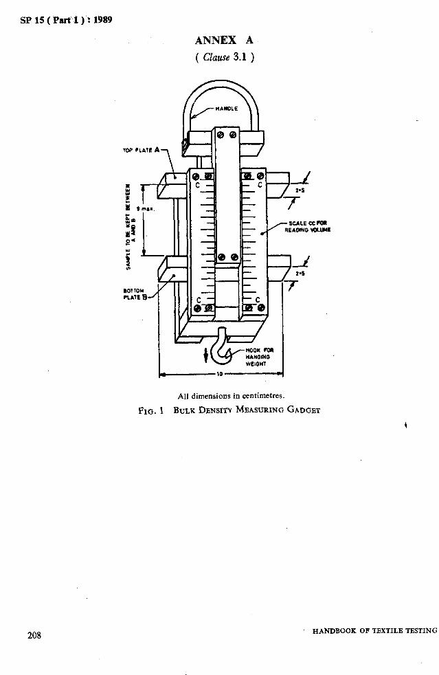
SP 15 ( Part 1 )‘:‘lW
ANNEX A
( Clause 3.1 )
- -
-
IF’ --- r- -9 / 29s I‘ 7
All dimensions in centimetres.
FIG. 1 BULK DENSITY MEASURING GADGET
208 HANDBOOK OF TBXTILB TBSTING

I--
1 SCOPE -
SP 15 ( Part 1) : i989
UNCUT INDIAN JUTE, MESTA AND BZMLZ BUNDLE STRENGTH
[ Source : IS 7032 ( Part 7 ) : 1986 ]
1.1 This standard prescribes a method for test- ing bundle strength of jute, MESTA and BIMLI fibres by tensile testing machines, working at constant rate of loading ( CRL ), constant rate of elongation ( CRE ) and constant rate of traverse ( CRT ).
load. The machines shall be provided with the following arrangements:
a) Two clamps with the following provisions to grip the specimens:
2 PRINCIPLE
2.1 A bundle of fibres of l-5 to 3.0 kilotex is gripped between two suitable clamps and their breaking load is determined on tensile testing machines. Then tenacity is calculated by divid- ing the breaking load by the mass of the fibres held between the clamps.
1) Each clamp shall be such that at least 10 mm of fibre length is gripped. There should be no slippage of fibres during test. To prevent slippage the inside of the clamps should preferably be lined with leather or rubber padding.
2) The clamps shall be capable of being adjusted on to 50 mm test length.
bj A scale or dial for recording the load in kilograms.
5 PROCEDURE
3 PREPARATION OF TEST SPECIMEN 5.1 Mounting the Test Specimen
3.1 Take clean portion of 200 mm in length at random from the middle region of the reeds ( leaving aside rooty bottom, crappy end and defects). Cut out sufficient length from each portion to cover fully both the clamps. The mass of each portion should be approximately 300 to 600 mg; heavier ones shall be thinned out from the side and to the lighter ones another reed or a portion of a reed shall be added. Make this adjustment simply by feel. Take 5 portions con- stituting 5 test specimens ( bundles).
Place the two clamps 50 mm apart. Put the fibre bundle in one of the clamps and tighten it. Straighten the fibres, putting a small tension and tighten it in the other clamp. If the clamps are detachable, these can be taken out of the machine, placed on a platform, separated 50 mm apart and the fibre bundle fixed as above. The clamps can then be inserted into the clamp holders on the machine. The fibre bundle should be parallel to the axis of the machine.
3.2 Similarly prepare at least 2 more sets of 5 specimens as in 3.1.
4 APPARATUS
5.2 With the help of preliminary specimen, set the machine so that the specimen breaks within 20 + 5 seconds. In the case of constant rate of traverse type machine set it at a rate of traverse so that the time of break exceeds the inertial period of the instrument.
4.1 Testing Machine
Tensile strength testing machine with a capa- city of 100 kgf or a little more working on one of the following principles:
5.3 Operate the machine and carry the test to rupture and record the breaking load of the specimen. If the specimen slips in the jaws the test shall be discarded but noted, and another test taken in view thereof.
a) Constant rate of traverse ( CRT ), b) Constant rate of load ( CRL ), or c) Constant rate of extension ( CRE ).
The specimens shall break within 20 -& 5 seconds. In case of constant rate of traverse machine the time of break shall exceed the inertial period of the instrument. The load range of the machine shall be such that the observed values would be between 10 and 90 percent of the full scale load. The permissible error in the machine at any point in this range shall not exceed fl percent of the maximum
NOTE - Even if a test value is isolated on account of break near the jaw, the value shall be noted but not taken into account in calculations. If such breaks exceed 10 percent of the number of specimens tested, suitable corrective action on the machine may have to be taken.
5.4 With a knife or sharp razor blade cut the fibres fiush at the inner edges of the two clamps and collect the tufts of fibres thus obtained. Test the other test specimens in similar manner.
5.4.1 Weigh the broken tufts of fibres for the 5 specimens together.
PART 1. SECTIQN D/22-7 I
209
BP 15 ( Part 1) : 1989
5.5 Test at least 3 groups of 5 specimens each in similar manner.
6 CORRECTION FACTORS
6.1 In case standard atmospheric conditions are not available, the samples may be condi- tioned and tested at the prevailing atmospheric conditions and the prevailing relative humidity shall be noted and correction applied for mass and breaking load as given below:
a) Correction for mass -~ Convert the mass
b>
of fibre bundles as obtained in 5.4.1 to equivalent mass at 65 percent relative humidity. For this purpose, the equili- brium moisture regain for jute corres- ponding to prevailing RH, will require to be determined from the regain humidity curve for jute or by using a suitable moisture regain meter. For example, if the moisture regain at the prevailing RH is R the corrected mass at 12 percent moisture regain corresponding to 65 per- cent RH will be given by the formula
Mx (100-c 12) 100 + R
( 12 is the approximate moisture regain of jute at 65 percent relative humidity ). Correction for breaking load - Convert the breaking load values obtained in 5.3 for the difference in relative humidity to breaking load at 65 precent relative humidity by multiplying with the appli- cable correction factor as given in Annex A. However, if the relative humidity is
between 35 to 75 nrecent, the correction for breaking load ;alne is. small and may be ignored.
The corrected values of mass and break- ing load shall be used in the formula given in 7.1.
_ 7 CALCULATION
7.1 Calculate the tenacity of the fibre by the following formula:
Tenacity ( in g/tex ), S = 50* x T
M
where
T = sum of the breaking load values of 5 bundles ,of fibres in kgf, and
M = total mass of all the bundles in milligrams.
7.2 Determine the average value of tenacity S from at least 3 sets of readings.
NOTE - When the difference between any two values of tenacity (S ) exceeds 15 percent of the mean, another value for S should be obtained and the average of four readings shall be reported.
8 REPORT
8.1 The report shall include the following information:
a) Type of machine, b) Number of test specimens tested, and c) Tenacity.
*This has been obtained by multiplying length by 10. The length indicated in 4.1 [ a ( 2 ) I is 5 cm.
210 HANDBOOK OF TBXTILB TESTING

SP 15 ( Part 1) : 1989
ANNEX A
[ Clause 6.1 (b) ]
FACTORS FOR CORRECTING BUNDLE STRENGTH OF JUTE AT DIFFERENT RELATIVE HUMIDITIES ( OR MOISTURE REGAINS ) TO STRENGTH AT 65 PERCENT RH
( 12.4 PERCENT MOISTURE REGAIN )
Equilibrium Moisture Crrrec tion Related Humidity Regain Factor
Percent Pert ent ( Multiply by )
10 3-o 1.35
15 3.9 1.21
20 4.8 l-13
25 5.7 l-08
30 6.5 l-05
35 7.0 1.03
40 8.0 1.01
45 8.7 I
50 9.5 1
55 10.5 : 1-o
60 11.5 !
65 12.4 1
70 13.5 l-01
72 14.0 1.02
75 15.0 l-03
80 16.5 1.06
85 18.8 l-09
90 22-o l-15
95 26.8 l-24
NOTE - No correction is necessary when the relative humidity of the testing atmosphere ranges between 35 and 75 percent.
PART 1, SECMON D/22-7 211

As in the Original Standard, this Page is Intentionally Left Blank
SP 15 ( Part I ) : 1989
UNCUT INDIAN JUT& MliX!‘A AND BZMLZ FINENESS
[ Source : IS 7032 ( Part 8 ) : 1986 ]
1 SCOPE
1.1 This standard prescribes a method for deter- mination of fineness of jute, MESTA and BIMLI fibres by air flow method.
2 PRINCIPLE
2.1 A specified mass of fibres is compressed to a constant volume in a cylindrical chamber with open ends to which a flowmeter and a manometer are connected. A regulated current of air is then passed through the compressed fibres and the average fibre fineness read from the scale. 3 APPARATUS
3.1 Air Flow Apparatus
It shall consist of the following principal parts: a) Constant Volume Chamber - for taking a
known mass of fibres and compressing it to a fixed known volume. It generally
. comprises: 1) a plug cell into which the fibres are
packed, 2) ;$Junger which dompresses the fibres,
3) a screw cap which clamps the plunger to the base.
b) Means for Air Regulation - for regulating and controlling the flow of air through or air pressure difference across the speci- men. It shall give sufficiently fine control of air supply so that the level of the flowmeter or manometer may be quickly adjusted to the working valve.
c) Means for Producing Air Flow - Capable of producing the required air pressure applied to the specimen or the required pressure difference across the specimen.
d) Means for Measuring the Resistance of Specimen to Air Flow or the Air Pressure D$erence Across the Specimen - The combination of manometer for maintain- ing the air pressure applied to the speci- men and a flowmeter for indicating the rate of air flow through the specimen may be used. Flowmeter or manometer shall be calibrated to directly read the fineness in tex or denier.
NOTE - Two suitable instruments developed by: (a) Ahmedabad Textile Industry’s Research Association, Ahmadabad (modified by Indian Jute Industries’ Research Association, Calcutta 1, and (b) Jute Technological Research Laboratories (ICAR ), Calcutta, are described in Annexes A and B.
PART 1, SECTION D/22-8 ’
3.2 Balance capable of weighing the specimen to an accu- racy of *5 mg. 3.3 Device for Fibre Cutting fibre cutter or a pair of scissors.
4 PREPARATION OF TEST SPECIMEN
4.1 Take a suitable portion at random from the middle regions ( leaving aside the rooty bottom and under-retted crop ends ) of several reeds, covering the full range of the sample. Clean each portion so as to free it from barky, specky and knotty spots, hard gummy fibres as well as other extraneous materials. If necessary the cut fibre reeds shall be lightly struck against a hard surface to shake off the adherent dirt and dust. Cut the fibre bundles to a specified length and take the’ mass of the fibres as requi- red by the instrument used (see Annexes A and B ).
5 PROCEDURE
5.0 Make the necessary preliminary adjust- ments appropriate to the instrument used. Ensure that the meniscus of the manometer is at the zero mark. 5.1 Place the test specinem in the fibre com- pression cylinder, taking care that all the fibres are placed inside. Adjust the machine as recommended by the instruction manual of the instrument ( see Annexes A and B ). 5.2 Cause the air to flow through the specimen and read the air flow or the difference in press- ures on the scale to an accuracy of half a divi- sion of the scale. 5.3 Remove the test specimen from the fibre compression cylinder and take one or two more readings on the same specimen as recommend- ed by the instruction manual of the instrument. 5.4 Take the other test specimens and deter- mine the test values in the manner set out in 5.1 to 5.3.
6 CALCULATIONS /
6.1 Calculate the average of all the values taken for all test specimens.
7 REPORT
7.1 The report shall include the following information:
4 The instrument used; b) Number of the specimens; and c> Fibre fineness in tex, or denier.
213
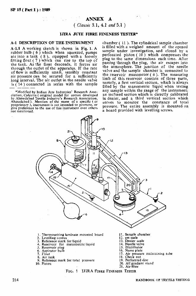
SP15(Partl):1989
ANNEX A ( Clauses 3.1, 4.1 and 5.1 )
IJIRA JUTE FIBRE FINENESS TESTER*
chamber ( 11 ). The cylindrical sample chamber is filled with a weighed amount of the opened sample under investigation, and closed by a perforated piston ( 10 ) which compresses the plug to the same dimensions each time. After passing through the plug, the air escapes into the atmosphere. The junction of the needle valve and the sample chamber is connected to the reservoir manometer ( 4 ). The measuring limb of this reservoir consists of three parts, namely, a first vertical section, which is always filled by the manometric liquid when testing any sample within the range of the instrument; an inclined section which is directly calibrated in denier, and a third vertical section which serves to monitor the constancy of total pressure. The entire assembly is mounted on a board provided with levelling screws.
A-l DESCRIPTION OF THE INSTRUMENT
A-l.1 A working sketch is shown in Fig. 1. A rubber bulb ( 6 ) which when squeezed, pumps air into a tank ( 8 ), equipped with a loosely fitting float ( 7 ) which can rise to the top of the tank. As the float descends, it forces air through the outlet of the apparatus. If the rate of flow is sufficiently small, sensibly constant air pressure can be secured for a sufficiently long interval. The air outlet in the needle valve is ( 14 ) connected in series with the sample
*Modified by Indian Jute Industries’ Research ASSO- ciation, Calcutta ( original model for cotton developed by Ahmedabad Textile Industry’s Research Association, Ahmadabad 1. Mention of the name of a specific ( or proprietary 1, instrument is not intended to promote, or give preference to the use of this instrument over others not mentioned.
Thermosetting laminate mounted board 11. Sample chamber Levelling screws 12. cm scale Reference mark for liquid 13. Denier scale Reservoir for manometric liquid 14. Needle valve Reservoir plug 15. Distributor Aspirator bulb 16. Name plate Float 17. Air pressure maintaining tube Air tank 18. Check nut Reference mark for total pressure 19. Perforated disc Piston 20. All gradient stand
21. Air filter FIG. 1 IJIRA FIBRB FINE.NBSS TESTER
214 HANDBOOK OF TBXTILB TESTING
SP 15 ( Part,1 ) : 1989
A-1.1.1 The calibrated section of the msnome- ter is inclined ( horizontal gradient 1 in 5 ) in order to increase the sensitivity and spread out the scale.
A-2 OPERATING PROCEDURE
A-2.1 Level the instrument with the help of the levelling screws and a spirit level.
A-2.2 Collect about 40 g of raw jute after pro- per sampling. Cut the fibre to approximately 1 cm pieces. Mix the cut fibres thoroughly and tease out by hand.
A-2.3 Divide the cut sample into 3 sub-samples. Weigh one specimen of 8.65 g from each sub - sample.
A-2.4 Pack the weighed sp:cim:ns into the sample chamber and close the chamber by piston ( 10 ).
A-2.5 Squeeze the aspirator bulb ( 6 ) a numb: r of times as that the float in thz tank ( 8 ) rises
to the top. Stop squeezing and the float will start descending. Observe the position of manometer liquid. At a certain point the manometer reading will remain steady for a while. Note the denier reading corresponding to this position of the manometer liquid.
A-2.6 Remove the specimen, Buff it out and repeat for a repeat test.
A-2.7 Repeat as in A-2.6. Altogether take 3 readings for each specimen.
A-2.8 Repeat the test for the other two speci- mens as in A-2.3 to A-2.7.
A-2.9 Find the average of the 9 readings.
A-3 CHECKING
A-3.1 In order to check from time to time that the instrument is performing satisfact-orily, readings should be taken on the calibration sample provided.
ANNEX B
( Clauses 3.1, 4.1 and 5.1 )
JTRL JUTE FIBRE FINENESS TESTER*
B-l DESCRIPTION OF THE INSTRUMENT
B-l.1 Air Flow Pr&ction Arrangement
The aspirator ( I in Fig. 2 ) is a wide flat tank T1 of 400 cm2 area with a narrow outlet O1 of 6 mm diameter. The tank is raised to suitable height ( 40 to 50 cm ) by a stand the outlet at O2 being extended below by a rubber tube E. This provides for a higher water head without having to handle a large quantity of water.
B-1.1.1 To maintain a constant water head, the top level drop has been neutralized by pulling down the end of the outlet rubber tube to some extent, such that the difference in water head ( H ) between the water level in the tank and the tip of the outlet 0, remains constant. This has been achieved by a simple device. The end 0, of the outlet rubber tube is attached to the top opening of the receiver T, hung from a spring. The spring is so adjusted that the weight of liquid being drained into the receiver is suffi- cient to extend the spring by an amount equal to the drop in the liquid level in the Tl. The constant level difference thus maintained ensures constant rate of flow.
*Mention of the name of a specific ( or proprietary ) instrument is not intended to promote, or give prefer- ence to the use of that instrument over others not mentioned.
PART 1, SECTION D/22-8
B-1.1.2 For refilling the tank Tl the receiver T, is hung upside down from a hook N above the tank Tl into which the receiver empties itself through the same rubber tube E. The tank T, has two openings, II and Ia, at the top, I1 having a tap, and one outlet with a tap at the bottom. The inlet tube I, is connected to the regulating valve Y and the other parts of the instrument, through it air is sucked in as water flows out of the tank. The tap I, provides an opening to the atmosphere during refilling. In the receiver T, also the side opening B maintains a connection between the inside and the outside atmosphere. The specification of the flow system are such that a maximum flow rate of about 15 ml per second can be mentioned for 25 seconds.
El.2 Flow Gauge!
The flow gauge ( II in Fig. 2 ) is essentially a manometer ( F1, F2 ), attached tb the two ends of a glass wool plug, or an equivalent glass or brass capillary tube Win a glass tube. For a particular flow rate through the plug, a diffe- rence of pressure develops between the ends of the plug and is indicated in this manometer. This manometer is calibrated in terms of flow rate, since pressure difference is proportional to the flow rate. The packing of the glass wool plug may be altered for different ranges of flow rate.
215

SP 15 ( Part 1) : 1989
FIBRE IN CELL
I n
I Aspirator 1, Tap II Flowmeter II Inlet tube
III Plug chamber J Stand IV Manometer N Hook
B Side opening ‘01 Narrow outlet C Chamber 02 End of the rubber tube
C1 Plug cell CI Centre open screw cap
PI, PI Pressure gauge T1 Tank
E Rubber tube Ta Receiver F1, Fz Manometer W Glass wool plug
H Water head Y Regulating valve
FIG. 2 INSTRUMENT FOR FIBRB FINENESS DETBRMINATION
B-1.2.1 To increase the sensitivity of the flow gauge manometer, the area of limb F, is made much larger than that of the other, such that the depression in the wider limb is negligible in comparison to the elevation of the liquid in the narrow limb, and further, the narrow limb is kept inclined at 60” to the vertical. A sliding scale is placed beside the narrow limb. The zero of the scale is made to coincide with the liquid meniscus before starting the test. If the meniscus level falls below a mark, some liquid may be added into the wider limb. The glass wool plug is so adjusted that the flow gauge manometer reading is changed from 0 to 26 cm with increase in flow rate from 0 to 15 ml per second.
El.3 Fibre Plug and the Chamber
A plug is formed of parallel fibre bundles. Such a plug is introduced longitudinally into a cylin- drical cell C1 of 1.25 cm diameter and 5 cm length ( 111 in Fig. 2 ). At one end, the cell has a flange which can be pressed air-tight on the rubber ring over the rim of a wider chamber C by a centre open screw cap 2.
B-1.3.1 The chamber is thus open to the atmos- phere at the top, and a small tube at the bottom
216
connects the chamber to the manometer and the other parts of the instrument.
B-l.4 Pressure Gauge
The pressure gauge P1, Pz ( IV in Fig. 2 ) is a manometer used for registering the difference of pressure between the two ends of the fibre plug. One end of the manometer as well as the fibre plug is open to the atmosphere. The design of the gauge is exactly similar to that of the mano- meter used for the flow gauge. The zero of the scale always set at the liquid meniscus before the experiment is started. B-2 FIBRE CUTTER
B-2.1 For a 5-cm plug cell, the fibre bundle has to be cut to 5 cm length. Fibre cutter ( Fig. 3 ) consists of a channel of rectangular cross section with a closely fitting plunger both cut exactly to 5 cm length. The fibre is placed longitudinally in the channel with ends project- ing on both sides. The plunger is then pressed by a crew, from the top. The projecting ends of the fibres are then cut flash with the channel ends by a chisel and hammer. The rota- table rectangular frame through which the crew works can be turned aside when the fibre is put
HANDBOOK OF TBXTILB TESTING

SP 15 ( Part 1 ) : 1989
in the channel. The plunger is provided with a projection ( not shown in Fig. 3 ) across the length to prevent tilting.
B-3 OPERATION OF THE INSTRUMENT
B-3.1 A group of raw jute fibre samples is cut to 5 cm length by the cutter and exactly 3 g are weighed out of it to form the test bundle. This mass is found suitable for the size of the plug cell used and is also specific for a particular calibration. The bundle is wrapped tightly in a paper strip and introduced into the plug cell Cl. The paper is then taken out or torn off by pushing the bundle gently either way, keeping the fibre ends flush with the cell ends. The cell is then fitted air-tight onto the chamber C.
B-3.1.1 The tank T, is filled with water and the top tap I, is closed. With the receiver on the spring S, the outlet tap 0,. is opened. The regu- lating valve Y is then manipulated to attain a fixed difference of pressure indicated on the pressure indicated on the pressure gauge. Imme- diately the flow gauge reading is taken.
RECTANGULAR
FJG. 3 FIBRB CUTTER
B-4 CALIBRATION OF ThE INSTRUMENT
B-4.1 Calibration of the Pressure Gauge Mano- meter
B-4.1.1 The fibre plug chamber C is disconnect- ed and the instrument connected to a vertically mounted U-tube manometer through the leg of a T-tube. One end of the head piece of the T-tube is connected to the U-tube manometer and the other end closed air-tight by means of a screw clip on a rubber tubing.
B-4.1.2 The water aspiration system is replaced by a suction pump which is connected to the regulating valve Y. The suction pump is run on and the regulating valve Y opened slowly to obtain a steady pressure difference in the U- tube manometer. The two liquid columns in the U-tube may be made level again by letting in air through the screw clip on the T-tube.
B-4.1.3 The steady pressure difference in the U-tube manometer is 9 cm with a manometric liquid ( kerosene oil ) of specific gravity O-82. The corresponding pressure gauge reading on the instrument is then marked on a scale placed beside it. For subsequent reading of the flow gauge, the air suction through the valve Y should be controlled so as to give this particu- lar valve of steady pressure on the pressure gauge manometer of the instrument.
B-4.2 Calibration of the Flow Gauge Manometer
B-4.2.1 Take a vertically mounted rotameter ( a flowmeter having a rotating indicator of air- flow ) and conne,ct a rubber tubing at the lower end. Clamp on the rubber tubing a screw clip to regulate Bir flow through the rotameter.
B-4.2.2 Disconnect the U-tube manometer and connect the upper end of the rotameter to this point. Run on the suction pump. Adjust the control valve Y and the screw clip of the rubber tubing attached to the rotameter alternately so as to have different flow rates at the particular steady pressure indicated by the pressure gauge manometer of the instrument (corresponding to a pressure head of 9 cm in the U-tube mano- meter referred to ).
B-4.2.3 Note down the rate of air flow in the rotameter, and mark this flow on the scale beside the flow gauge manometer of the instru- ment. A number of flow rates all at the steady pressure difference, are thus marked on the flow gauge scale. A calibration curve is drawn relating flow rates (ml/s ) and scale length ( cm ) of the flow gauge. This calibration curve is used to find out the different ‘tex’ values corresponding to the different flow rates by using the formula, tex =;i O-283 x flow in ml/s. The flow gauge scale is then calibrated directly in terms of tex values.
B-5 SENSITIVITY OF THE INSTRUMENT
B-5.1 Since both the pressure and the flow gauges are sensitive enough to detect a change of 1 mm in reading, the approximately error of observation is not likely to excceed 2 percent, when the pressure gauge stands at 18.0 cm and the flow gauge between 6-O and 26-O cm. Consi- dering the variation within a sample: this order of sensitivity seems to be sufficient for textile fibres. A 3-g bundle may be made to represent as many regions as possible, to minimize the variation between readings.
217 PART 1, SECTION D/22-8

As in the Original Standard, this Page is Intentionally Left Blank
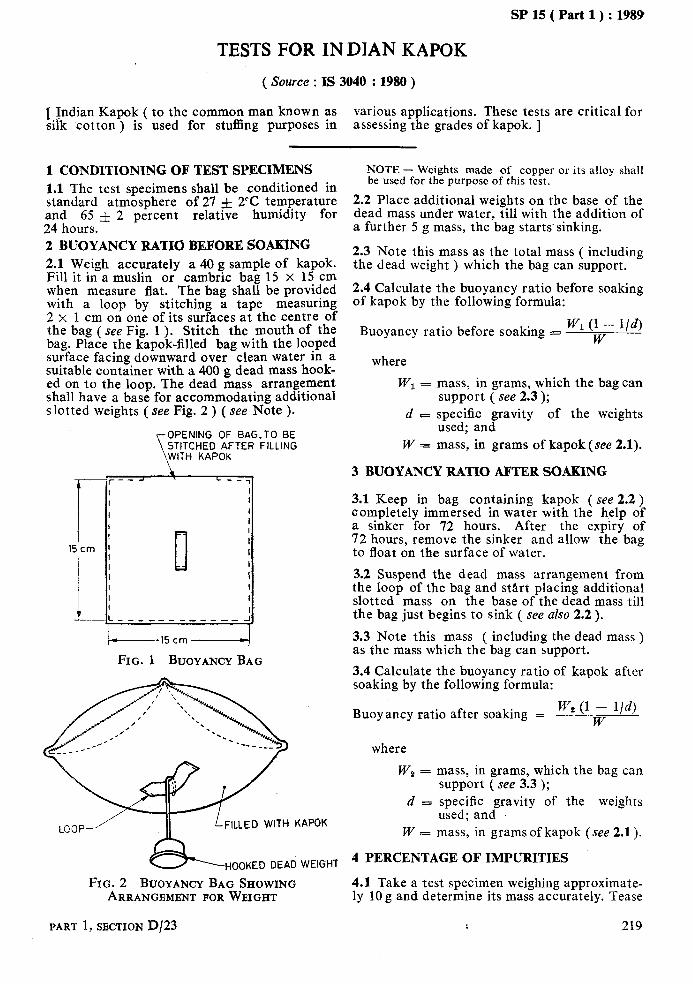
SP lS(Part1):1989
TESTS FOR INDIAN KAPOK
(Source : IS 3040 :1980)
1 Indian Kapok ( to the common man known as silk ‘cotton ) is used for stuffing purposes in
various applications. These tests are critical for assessing the grades of kapok. ]
1 CONDITIONING OF TEST SPECIMENS 1.1 The test specimens shall be conditioned in standard atmosphere of 27 f 2% temperature and 65 f 2 percent relative humidity for 24 hours. 2 BUOYANCY RATIO BEFORE SOAKING 2.1 Weigh accurately a 40 g sample of kapok. Fill it in a muslin or cambric bag 15 x 15 cm when measure flat. The bag shall be provided with a loop by stitching a tape measuring 2 x 1 cm on one of its surfaces at the centre of the bag ( see Fig. 1 ). Stitch the mouth of the bag. Place the kapok-filled bag with the looped surface facing downward over clean water in a suitable container with a 400 g dead mass hook- ed on to the loop. The dead mass arrangement shall have a base for accommodating additional slotted weights ( see Fig. 2 ) ( see Note ).
OPENING OF BAG.TO BE STITCHED AFTER FILLING
c r--_ L ---I
I I
I I
I I
I I
I
15cm 1 0 I I
I I I I
L\--__-__-____I 15 cm
FIG. 1 BUOYANCY BAG
FILLED WITH KAPOK
HOOKED DEAD WEIGHT
FIG. 2 BUOYANCY BAG SHOWING 4.1 Take a test specimen weighing approximate- ARRANGBMBNT FOR WEIGHT ly 10 g and determine its mass accurately. Tease
NOTE - Weights made of copper or its alloy shall be used for the purpose of this test.
2.2 Place additional weights on the base of the dead mass under water, till with the addition of a further 5 g mass, the bag starts’ sinking.
,
2.3 Note this mass as the total mass ( including the dead weight ) which the bag can support.
2.4 Calculate the buoyancy ratio before soaking of kapok by the following formula:
Buoyancy ratio before soaking = Wl(1 - l/d) w
where
W, = mass, in grams, which the bag can support ( see 2.3 );
d s specific gravity of the weights used; and
W = mass, in grams of kapok (see 2.1).
3 BUOYANCY RATIO AFTER SOAKING
3.1 Keep in bag containing kapok ( see 2.2 ) completely immersed in water with the help of a sinker for 72 hours. After the expiry of 72 hours, remove the sinker and allow the bag to float on the surface of water.
3.2 Suspend the dead mass arrangement from the loop of the bag and start placing additional slotted mass on the base of the dead mass till the bag just begins to sink ( see also 2.2 ).
3.3 Note this mass ( including the dead mass ) as the mass which the bag can support.
3.4 Calculate the buoyancy ratio of kapok after soaking by the following formula:
Buoyancy ratio after soaking = W, (1 - l/d) W
where
W:, = mass, in grams, which the bag can support ( see 3.3 );
d = specific gravity of the weights used; and
W = mass, in grams of kapok (see 2.1).
4 PERCENTAGE OF IMPURITIES
PART 1, SBCTION D/23 1 219

I SP 15 ( Part 1 ) : 1989
the specimen thoroughly by hand to clean put where seeds, seed coat particles, leafy bits, dust and dirt, etc. The impurities thus separated shall be W 1= mass of test specimen, and weighed accurately. Determine the percentage W = mass of impurities. of impurities by the following formula: 4.2 Repeat the test on two more test specimens
Impurities, percent = w, x 100 and determine the average impurities percentage w of three test specimens.
220 HANDBOOK OF TEXTILE TESTING
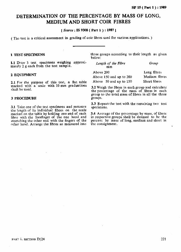
SP 15 ( Part 1) : 1989
DETERMINATION OF THE PERCENTAGE BY MASS OF LONG, MEDIUM AND SHORT COIR FIBRES
[ Source : IS 9308 ( Part 1 ) : 1987 1
( The test is a critical assessment in grading of coir fibres used for various applications. )
1 TEST SPECIMENS three groups according to their length as given below:
1.1 Draw 3 test specimens weighing approxi- mately 2 g each from the test sample.
Length of the Fibre mm
2 EQUIPMENT
2.1 For the purpose of this test, a flat table marked with a scale with 10 mm graduations shall be used.
3 PROCEDURE
Above 200 Long fibres Above 150 and up to 200 Medium fibres Above 50 and up to 150 Short fibres
3.2 Weigh the fibres in each group and calculate the percentage of the mass of fibres in each group to the total mass of fibres in all the three groups.
3.1 Take one of the test specimens and measure the length of its individual fibres on the scale marked on the table by holding one end of each fibre with the forefinger of the one hand and stretching the other end with the fingers of the other hand. Arrange the fibres so measured into
3.3 Repeatdthe test with the remaining two test specimens.
3.4 Average of the percentage by mass, of fibres in respective groups shall be deemed to be the percent by mass of long, medium and short in the consignment.
Group
PART 1,SECTION D/24 221

As in the Original Standard, this Page is Intentionally Left Blank
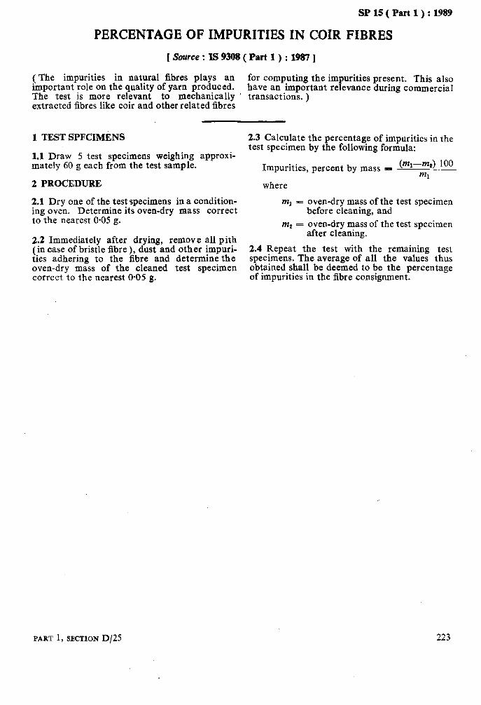
SP 15( Part 1):1989
PERCENTAGE OF IMPURITIES IN COIR FIBRES
[ Source : IS 9308 ( Part 1 ) : 1987 ]
(The impurities in natural fibres plays an important role on the quality of yarn produced.
for computing the impurities present. This also have an important relevance during commercial
The test is more relevant to mechanically ’ transactions. ) extracted fibres like coir and other related fibres
1 TEST SPFCIMENS 2.3 Calculate the percentage of impurities in the
1.1 Draw 5 test specimens weighing approxi- test specimen by the following formula:
I
mately 60 g each from the test sample. Impurities, percent by mass = (mi-m~) 100 ml
2 PROCEDURE where
2.1 Dry one of the test specimens in a condition- ml - oven-dry mass of the test specimen ing oven. Determine its oven-dry mass correct before cleaning, and to the nearest O-05 g. m2 = oven-dry mass of the test specimen
2.2 Immediately after drying, remove all pith after cleaning.
(in case of bristle fibre 1. dust and other imnuri- 2.4 ReDeat the test with the remaining test &es adhering to the &bre and determine the specimens. The average of all the values thus oven-dry mass of the cleaned test specimen obtained shall be deemed to be the percentage correct to the nearest 0.05 g. of impurities in the fibre consignment.
PART 1, SECTION D/25 223

As in the Original Standard, this Page is Intentionally Left Blank
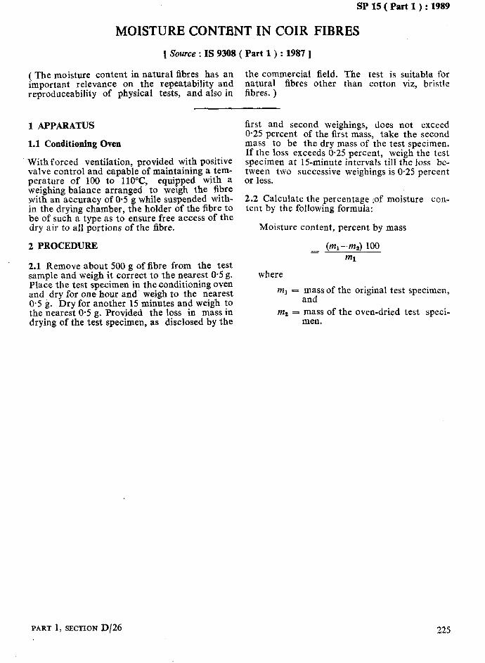
.
SP 15 ( Part 1 ) : 1989
MOISTURE CONTENT IN COIR FIBRES
[ Source : IS 9308 ( Part 1) : 1987 J
( The moisture content in natural fibres has an the commercial field. The test is suitable for important relevance on the repeatability and natural fibres other than cotton viz, bristle reproduceability of physical tests, and also in fibres. )
1 APPARATUS
1.1 Conditioning Oven
With forced ventilation, provided with positive valve control and capable of maintaining a tem- perature of 100 to llO”C, equipped with a weighing balance arranged to weigh the fibre pith an accuracy of 05 g while suspended with- m the drying chamber, the holder of the fibre to be of such a type as to ensure free access of the dry air to all portions of the fibre.
2 PROCEDURE
2.1 Remove about 500 g of fibre from the test sample and weigh it correct to the nearest 0.5 g. Place the test specimen in the conditioning oven and dry for one hour and weigh to the nearest 0.5 g. Dry for another 15 minutes and weigh to the nearest O-5 g. Provided the loss in mass in drying of the test specimen, as disclosed by the
first and second weighings, does not exceed 0.25 percent of the first mass, take the second mass to be the dry mass of the test specimen. If the loss exceeds 0.25 percent, weigh the test specimen at 15-minute intervals till the loss be- tween two successive weighings is 0.25 percent or less.
2.2 Calculate the percentage :of moisture con- tent by the following formula:
Moisture content, percent by mass
where
ml = mass of the original test specimen, and
m2 = mass of the oven-dried test speci- men.
PART 1, SECTION D/26 225

As in the Original Standard, this Page is Intentionally Left Blank
SECTION E
CHEMICALTESTSFORTEXTILEFIBRES

As in the Original Standard, this Page is Intentionally Left Blank

SP 15 ( P-t i ) : 1989
ESTIMATION OF CARBOXYLIC ACID GROUPS IN CELLULOSIC TEXTILE MATERIALS - IODOMETRIC METHOD ’
[Sowce:IS156O(Part1):1974]
In the cellulosic textile industry, cellulose in the form of fibres, yarn and fabric comes in con-
tent of carboxylic acid groups. The absorption of metallic ions from aqueous solutions of their
tact with different oxidizing agents during the salts is an outstanding property of oxycelluloses. various chemical processing treatments. The This property in celluloses and oxycelluloses is action of these oxidizing agents on cellulose may result in the formati0.n of oxycelluloses of
due to the presence of carboxylic acid groups in
acidic character attributable to the introduction them. The estimation of carboxylic acid groups present in cellulosic textile materials is a
of carboxyl groups into the cellulose chain molecule. Purified cotton cellulose, not subject-
method of determining the extent of this type of
ed to any treatment with oxidizing agents, also oxidation of cellulose. This is a useful supple-
behaves as though it possesses a very small con- mentary test to other tests such as copper number and fluidity tests.
1 SCOPE
1.1 This standard prescribes the iodometric method for estimation of carboxylic acid groups in cellulosic textile materials.
2 PRINCIPLE
2.1 Cation-free cellulosic material is suspended in potassium iodide-potassium iodate-sodium chloride solution to which sodium thiosulphate is added to prevent the loss of iodine due to side reactions and vaporization as also to facilitate the completion of the reaction by removal of th.e iodine liberated from the sphere of reaction. At the end of the requisite period, the excess of thiosulphate is titrated back with standard iodine solution, and the amount of thiosulphate consumed indicates the extent of carboxyl content.
3 PREPARATION OF TEST SPECIMENS
3.1 Cut the sample under test into small pieces. Mix all the pieces thoroughly and draw at least two specimens, each weighing about 2 g.
4 APPARATUS
4.1 Automatic Burette
of 50 ml capacity.
4.2 Erlenmeyer Flask
of Pyrex glass ( or similar heat-resistant glass ) , fitted with a glass-stopper and of 250 ml capa- city.
4.3 Small Compressor; Vacuum Pump or Water Jet Pump
for blowing air; capable of producing a pressure sufficient to stir the liquid in the flask during titration.
PART 1, SECTION E/l-l
5 REAGENTS
5.1 Quality of Reagents
5.1.1 Unless specified otherwise, pure chemicals shall be employed in the test and distilled water shall be used where the use of water as reagent is intended.
NOTE - ‘Pure chemicals’ shall mean chemicals that do not contain impurities which affect the test results.
5.1.2 All reagents shall be prepared using carbon dioxide-free distilled water which may be obtained by the method prescribed in Annex A. All reagents shall be stored in containers with sodalime traps in order to protect the reagents from coming into contact with atmospheric carbon dioxide.
5.2 The reagents required for the test shall be as given below.
5.2.1 Potassium Iodide-Potassium Iodate-Sodium - Chloride Solution
Prepare the solution by dissolving the following reagents in the quantities indicated against each in carbon dioxide-free distilled water to make 2 litres:
g Potassium iodide ( analytical grade ) 83.0 Potassium iodate ( analytical grade ) 21.0 Sodium chloride ( analytical grade ) 50.0 Sodium thiosulphate ( analytical grade) 5.0
5.2.2 Standard Sodium Thiosulphate Solution
0.02 N.
5.2.3 Iodine Solution
0.02 N. Dissolve 2.6 g of iodine and 4 g of pota- ssium iodide in about 25 ml of water by warm- ing gently. Dilute the solution to 1 litre.
229

SPlS(Part1):1989
Standardize against standard thiosulphate salution.
5.2.4 Starch Solution
0.2 percent (m/v).
5.2.5 Hydrochloric Acid Solution
approximately 0.5 N.
6 PROCEDURE
calculate the oven-dry mass of the cation-free specimen taken for the test ( see 6.2 ). 6.5 Repeat the test with the remaining test specimen(s). ,
7 CALCULATION
6.1 Take one test specimen and steep it for 2 hours in 0.5 N hydrochloric acid at room tem- perature, keeping the material to liquor ratio as 1 : 50. Wash the specimen on a suction filter thoroughly with distilled water till the washings are neutral ( as indicated by bromocresol pur- ple ). Dry the specimen in air.
7.1 Calculate the carboxylic acid group content of each specimen, in mill&equivalents of COOH per 100 g, of the sample, by the follow- ing formula:
Carboxylic acid group content, expressed as milli-equivalents of COOH per 100 g of
NOTE - The above treatment renders the specimen cation-free.
sample
=
where vr =
6.2 Transfer from the automatic burrette 50 ml of the solution prepared as in 5.2.1 to the Erlenmeyer flask. Weigh accurately 0.5 to 1.0 g of air-dry cation-free specimen ( see 6.1) and transfer it to the flask. Stopper the flask, shake it gently to mix the contents thoroughly and immerse it in a water-bath maintained at 60 f 1°C for 1 hour. Cool the flask quickly and titrate the excess of thiosulphate solution against 0.02 N iodine solution using starch as indicator. Bubble by means of a compressor or a vacuum pump or a water jet pump carbon dioxide-free air through the mixture throughout the titration.
7.2 Calculate the average of the values obtained as in 6.1.
8 REPORT 6.3 Carry out a blank titration following the same procedure ( see 6.2 ) but without the test specimen. 6.4 Determine the moisture content of the cation-free material ( see 6.1) separately and
ANNEX A ( Clause 5.1.2 )
The report shall include the following: a) Type of material, b) Carboxylic acid group content, and c) Number of specimens tested.
,
v, =
N= M=
(V, - V,) x N x 100 M
quantity in millimetres of iodine solution required for the blank ( see 6.3 ), quantity in millimetres of iodine solution required for aftual test ( see 6.2 ), normality of iodine solution, and oven-dry mass in gram of the cation-free specimen taken for the test ( see 6.4 ).
METHOD FOR PREPARATION OF CARBON DIOXIDE-FREE DISTILLED WATER
A-l APPARATUS A-l.1 Flask of hard glass, fitted with a stopper and of required capacity. A-l.2 Nessler Tube .
of thin colourless glass, with flat bottom, about 25 mm in diameter and about 150 mm in length.
A-2 REAGENT
A-3.2 Transfer 25 ml of the boiled distilled water to the Nessler tube. Add to it 25 ml of saturated calcium hydroxide solution and mix well. After 5 minutes, observe whether there is any turbidity of precipitate.
A-3.3 Take the distilled water to be free from carbon dioxide if no turbidity or precipitate is observed ( see A-3.4 ). Stopper the flask and cool the content.
A-2.1 Saturated Calcium Hydroxide Solution
A-3 PROCEDURE A-3.1 Boil the required amount of distilled water in the flask for about 5 minutes.
A-3.4 If, however, turbidity or precipitate is observed, repeat as many times as may be necessary the procedure prescribed in A-3.1 and A-3.2.
230 HANDBOOK OF TKXTILE TESTING,
Sl?l5(Part1):1989
ESTIMATION OF CARBOXYLIC ACID GROUPS Il’yI CELLULOSIC TEXTILE’ MATERIALS: SODIUM CHLORIDE-SODIUM
BICARBONATE METHOD
[ Source : IS 1560 ( Part 2 ) : 1974 1
1 SCOPE 5.2.2 Hydrochloric Acid
1.1 This standard prescribes the sodium chlo- ride-sodium bicarbonate method for estimation of carboxyl acid group content of cellulose textile materials.
1 : 99. Dilute 1 volume of concentrated hydro- chloric acid ( sp gr 1.19 ) with 99 volumes of water.
5.2.3 Methyl Red Indicator Solution
2 PRINCIPLE
2.1 Sample is de-ashed with hydrochloric acid, washed, soaked in sodium chloride-sodium bicarbonate solution and then filtered off. An aliquot of the filterate is titrated with O-01 N hydrochloric acid to a methyl red end point. The amount of the sodium chloride-sodium bicarbonate solution consumed is a measure of the ion-exchange capacity of the cellulose and indicates the extent of carboxyl content.
5.2.4 Sodium Chloride - Sodium Bicarbonate Solu- tion
Dissolve 5.85 g of sodium chloride and 0.84 g of sodium bicarbonate in water and dilute to 1 litre.
5.2.5 Sodium Hydroxide Solution
0.4 g/l.
5.2.6 Water Saturated with Carbon Dioxide
3 PREPARATION OF TEST SPECIMENS 6 PROCEDURE
3.1 Condition the sample under test in the pre- vailing atmosphere for at least 20 minutes and cut it into small pieces. Mix all the pieces thoroughly and draw at least 2 test specimens, each weighing about 2-5 g. At the same time draw specimens for moisture content determi- nation.
4 APPARATUS
4.1 Fritted Glass Funnels
4.2 Erlenmeyer Flask
of Pyrex glass ( or similar heat-resistant glass ), fitted with a glass stopper and of 250 ml capa- city.
5 REAGENTS
5.1 Quality of Reagents
Unless specified otherwise, pure chemicals shall be employed in the test and distilled water shall be used where the use of water as reagent is intended.
6.1 Weigh one test specimen accurately, disin- tegrate it in water and filter through a fritted glass funnel. Disperse the disintegrated speci- men to about 1 percent consistency in hydro- chloric acid (1 : 99) at room temperature. After 2 hours collect the specimen on a fritted glass funnel and wash with water saturated with carbon dioxide. Continue washing until the filtrate, after boiling does not require more than two drops of sodium hydroxide solution to give an alkaline colour ( yellow ) with methyl red.
6.2 Weigh the wet pulp pad, transfer it to an Erlenmeyer flask, and 5 ml of the sodium chloride-sodium bicarbonate solution with a pipette and shake to obtain a homogeneous slurry ( see Note ). Allow the mixture to stand for 1 hour at room temperature. Filter through a clean, dry fritted glass funnel. Pipette 25 mI aliquot of the filtrate into an Erlenmeyer flask and titrate with 0.01 N hydrochloric acid using methyl red indicator. When the first change in colour occurs, boil the solution for about 1 minute to expel carbon dioxide and continue the titration to a sharp end point.
NOTE - ‘Pure chemicals’ shall mean chemicals that do not contain impurities which affect the test results.
5.2 The reagents required for the test shall be as given below.
5.2.1 Hydrochloric Acid
0.01 N.
NOTE - If the cation exchange capacity is very low, use a solution containing about 5’85 g of sodium chloride and 0’42 g of sodium bicarbonate per litre. It is important that the excess of sodium bicarbonate should be large enough so that the pH does not fall below 7’0.
6.3 Blank
Pipette 25 ml of sodium chloride-sodium bicar- bonate solution into an Erlenmeyer flask and titrate as in 6.2.
PART 1, SECTION E/1-2
.
231

SPlS(Partl):l!XN
6.4 Determine the moisture content of the sample using the specimens taken for the pur- pose ( see 3.1) and calculate the oven-dry mass of the specimen taken for the test ( see 6.1 ).
6.5 Similarly test other test specimen(s).
7 CALCULATION
7.1 Calculate the carboxylic acid group content of each specimen, in milli-equivalents of - COOH per 100 g of the specimen, by the follow- ing formula:
Carboxylic acid group content, as milli-equivalents of-COOH per 100 g of specimen
= ( v, - v, - V*rn 2 50
> -J-g
where VI = quantity in millimetres of 0.01 N
hydrochloric acid consumed in the blank ( see 6.3 ),
vz = quantity in millimetres of 0.01 N hydrochloric acid consumed in the actual test ( see 6.2 ),
m = mass in grams of water in the wet pulp pad, and
M- oven-dry mass in grams of test specimen ( see 6.4 ).
7.2 Calculate the average of the values obtained as in 7.1.
8 REPORT
The report shall include the following: a) Type of material, b) Carboxylic acid group content, and c) Number of specimens tested.
.
232 HANDBOOK OF TEXTILE TESTING
SP 15 ( Part 1) : -1989
DETERMINATION OF ACETIC ACID CONTENT OF ACETATE OR TRIACETATE FIBRE MATERIALS
( Source : IS 12135 : 1987 )
Acetic acid content of acetate or triacetate lose and is useful in ascertaining chemicai fibres is an important parameter for controlling damage to acetate or triacetate fibres during the degree of acetylation of regenerated cellu- processing by cuprammonium fluidity test.
l SCOPE
1.1 This standard prescribes a method for determination of acetic acid content of acetate ,or triacetate fibre materials.
1.2 The method prescribed in this standard is not applicable to acetate and triacetate fibre materials containing sizing and finishing subs- tances such as polyvinyl acetate, polyacrylic or polymethacrylic acid, cellulose ether, carbonic acid, etc, the presence of which may falsify the results of titration.
1.3 While testing dyed or printed specimens, there is a possibility that the dye may get dissolved and hence make it difficult to recog- nize the colour change during titration. In such a case, the titration should be carried out electrometrically.
2 PRINCIPLE
2.1 The acetate fibres are saponified with alcoho- lic potash lye. The acetic acid content is deter- mined by the amount of alkaliused to reach the end point, titrimetrically.
3 APPARATUS
3.1 Weighing Glass
3.2 Desiccator with Blue Gel Filling
3.3 Analytical Balance with an Img
accuracy up to
3.4 Air Drying Oven Capable of 105 &- 2°C
Maintaining at
3.5 1 000 ml Measuring Flask
3.6 200 ml Erlenmeyer Flask Stopper
with Ground
3.7 50 m4 Pipette
3.8 Burette
3.9 1 000 ml Erlenmeyer Flask
4 REAGENTS
4.0 Quality of Reagents Unless specified otherwise, pure chemicals shall be employed in tests and distilled water shall be used.
NOTE - ‘Pure chemicals’ shall mean chemicals that do not contain impurities which affect the test results.
4.1 Alcoholic Potash Lye
1 M, potassium hydroxide ( free of carbonate ) in tablet form dissolved in ethanol.
4.2 Hydrochloric Acid
1 M.
4.3 Caustic Soda Lye
1 M.
4.4 Phenolphathelein Solution
1 g phenolphathelein dissolved in 95 ml of ethanol and 5 ml distilled water.
5 PREPARATION OF TEST SPECIMEN
5.1 From the test sample after removing size and finish draw a representative specimen weighing 20 f 0.1 g. Cut test specimen into pieces of approximately 25 mm length. Take at least two such test specimens.
6 PROCEDURE
6.1 Dry the test specimen ( 5.1) in the weighing glass at 105 f 2°C temperature in a drying oven to constant mass. The mass shall be taken as constant when the difference between two successive weighings at an interval of 20 minutes does not exceed 0.1 percent. Cool the dried test specimen in the desiccator and weigh it correct to 1 mg.
6.2 Transfer the weighed test specimen ( 6.1 ) into a 200 ml Erlenmeyer flask. Add to it 50.0 ml of 1 M alcoholic potash lye, close the flask and leave it for 48 hours at room tempe- rature. Then add to it 50.0 ml of 1 M hydro- chloric acid, shake the flask thoroughly for 5 minutes and leave it for one more hour at room temperature.
6.3 Wash the contents of the Eilenmeyer flask with about 500 ml of distilled water in the 1 000 ml Erlenmeyer flask.
4.4 Titrate the contents of the flask ( 6.3 ), after addition of three drops of phenolphathe- lein solution with 1 M of caustic soda lye.
PART 1, SECTION E/‘2 233
,kP 15 ( Part 1) : 1989
6.5 Find out the amount of caustic soda lye used in ml. 6.6 Repeat the procedure from 6.1 to 6.5 with other test specimens and find the amount of caustic soda lye consumed, in ml, for each test specimen. 7 CALCULATION 7.1 Calculate the acetic acid content of all the test specimens separately with reference to dried fibre material by the formula:
Acetic acid content, percent = -+ x 100
where Q = the amount of 1 M caustic soda
lye in ml ( see 6.5 and 6.6 ), and
E- the weighed amount of; the dried f&re material in g as obtained in
. . I
7.2 Find out the average acetic acid content, percent of the fibre material.
8 REPORT
The test report shall indicate the following:
a>
b)
Type and quality of the textile material tested, and
Acetic acid content, percent, rounded to three significant figures ( individual values and the mean value separate ).
234 HANDBOOK OF TEXTILE TESTING

4 SP 15 ( Part 1) : 1989
DAMAGE IN COTTON FIBRES DUE TO MICRO-ORGANISMS
( Source : IS
Cotton fibres are liable to be attacked and damaged by micro-organisms, such as bacteria and fungi at three stages (i) during cultivation as cotton bolls on plants, (ii) after harvest as KAPAS in the farm storage, and (iii) as lint during transit and storage in godown. The deterioration is promoted by climatic condi- tions prevalent in tropical and subtropical countries.
Moisture is essential for the development and growth of micro-organisms, the amount of mois- ture required being dependent upon the type of organisms. Thus, fungi usually develop when the relative humidity of the environment appro- aches about 75 percent and the growth is rapid when the relative humidity is above 85 percent. Bacteria, on the other hand, are active only when the substrate on which they are present is itself wet.
During cultivation the cotton plants and parti-
2964 : 1964 )
cularly the cotton bolls suffer microbial attack by micro-organisms from soil or environment. The extent of damage is governed by the micro- climate and the type of plant.
Fungi may appear as fine downy growth or as dark spots or stains causing discolouration of fibres and forming fibrelocks in cotton bolls. Mould growth may affect bunch of fibres in limited and isolated regions with no tendering in between two such regions. But if the fibres had been in contact with soil or contaminated with it and then exposed to dampness, the entire fibre or whole of fibrelocks may show uniform tendering.
The degree of growth of micro-organisms as well as their tendering effect may differ widely from fibre to fibre and within a fibreitself. It is, therefore, not necessary to submit the results of tests prescribed in this method to statistical analysis.
1 SCOPE
1.1 This standard prescribes methods for the detection and estimation of damage in cotton fibres due to micro-organisms.
1.1.1 The methods are applicable to cotton fibres in boll stage and also during storage and transit from the farm to the industry.
2 TEST SPECIMENS AND CONTROL SPECIMENS
2.1 From the test sample draw at random 15 specimens each weighing about 5 g; these shall constitute the test specimens for the purpose of 4.2.1, 4.2.2., 4.2.4, 4.3.1, 4.3.2 and 5.1.1.
2.2 From that portion of the sample from which test sample has been separated, draw at random six specimens each weighing about 5, g; these shall constitute the control specimens for the purpose of 5.2.3, 5.2.5 and 6.1.3.
3 REAGENTS
3.0 Quality of Reagents
Unless specified otherwise, pure chemicals shall be employed in tests and distilled water shall be used where the use of water or distilled water as a reagent is intended.
NOTE - ‘Pure chemicals’ shall mean chemicals that do not contain impurities which affect the experimen- tal results.
3.1 Balloon Test Reagents
Prepared by dissolving 15 g o caustic soda in 85 ml of water and mixing equal parts of this solution and carbon disulphide.
3.2 Lactophenol Solution
Prepared by dissolving 100 g of phenol in 100 ml of water and adding to the solution 100 ml each of glycerine and lactic acid.
3.3 Cotton Blue Solution
Prepared by making a saturated solution ( about 25 ml ) of cotton blue ( Colour Index No. 51190 ) in 95 per cent alcohol and adding to 10 ml of this solution 10 ml of glycerine and 80 ml of water.
3.4 Cotton Blue-Lactophenol Solution
Prepared by mixing equal volumes of cotton blue and lactophenol solutions.
3.5 Congo Red Solution
Prepared by making a 2 percent solution of Congo red ( Colour Index No. 22120 ) in water.
3.6 Caustic Soda Solutions
(i) Prepared by dissolving 11 g of caustic soda in 89 ml of water, and (ii) prepared by dissolv- ing 18 g of caustic soda in 82 ml of water.
PART 1, SECTION E/3 235
SP 15 ( Part 1) : 1989
4 DETECTION OF DAMAGE
4.1 Apparatus
The following apparatus shall be used:
a) Electrical pH meter or Lovibond compa- rator, and
b) Microscope with a magnification range of 50 to 900.
4.2 Procedure
4.2.1 Draw about one gram of the fibres from one of the specimens drawn as in 2.1, place it in a clean, dry, wide-mouthed glass-stoppered bottle ( 50 ml capacity ) and leave it at room temperature ( temperature range 25-28°C ) for three hours. Remove the stopper and smell the contents of the bottle, taking a deep breath.
NOTE - The presence of characteristic musty odour is indicative of the growth and attack of micro-orga- nisms. If the test samples are damp, the odour will be dominant.
4.2.2 From another test specimen drawn as in 2.1, take about one gram of the fibres and cut them into small bits. Take a wide-mouthed conical flask and rinse it thoroughly with dis- tilled water. Place the bits in the flask, add 10 ml of distilled water and boil for half an hour. Take the supernatant liquid and deter- mine its pH value with the pH meter or Lovi- bond comparator, noting down the temperature of the supernatant liquid.
4.2.3 Determine the pH value of the aqueous extract of the control specimen drawn as in 2.2, following the procedure prescribed in 4.2.2.
NOTE - With fungal attack the pH value generally shifts towards the acid side, whereas with bacterial attack it generally shifts towards the alkaline side.
4.2.4 Take about 50 to 60 fibres from the test specimen drawn as in 2.1, mount them parallel on a glass side, cover them with a cover plate and treat them with balloon test reagent. Examine the fibres under microscope after 30 minutes.
4.2.5 Treat similarly the fibres from a control specimen drawn as in 2.2 and examine them under microscope.
NOTE - Undamaged fibres will show formation of balloons or beads (see Fig. 1 ) whereas damaged fibres will not show formation of any balloons or beads (see Fig. 2).
4.3 Detection of Fungal or Bacterial Damage 4.3.1 From four test specimens take few fibres from the stained portions, mount them on a glass slide and irrigate them with a few drops of lactophenol solution. Cover the fibres with a cover plate and examine them under micro- scope.
NOTE - The presence of spores, fungal fructifica- tions and hyphae indicate damage due to fungi ( see Fig. 3 ).
4.3.2 Take a sufficient number of fibres from four test specimens and place them in a watch- glass. Treat the fibres with a few drops of cotton blue-lactophenol solution for 1 to 2 minutes. Remove the colour from the surface of the fibres by treating them with lactophenol solution. Mount these fibres on a number of glass slides in lactophenol and examine them under the microscope.
NOTE -A magnification of 50 to 500, should be used for deiection of damage due to fungal attack and a magnification of 500 to 900 should be used for detection of damage due to bacterial attack.
4.3.3 If, under a magnification of 50 to 500, the slides prepared as in 4.3.2 ( see Fig. 4, 5 and 6 ) show, as compared to undamaged fibre ( see Fig. 7 ).
a) incisions or cracks on the cuticle of the fibre, and/or
b) damage to primary and secondary walls of the fibre from the cuticle inwards, and/or
c) hyphae within the lumen. report the lot to have been damaged by fungal attack. If, under a magnification of 500 to 900, the slides prepared as in 4.3.2 ( see Fig. 8 and 9, and Note 1 ) show, as compared to undamaged fibre (see Fig. 7 > indentations or serrations of the fibres from the cuticle inwards, that is towards the lumen, report the lot to have been damaged by bacterial attack ( see Note 2 ).
NOTES
1 The extent of indentations or serrations is a eood indication of the intensitv of bacterial damaae. yhough in the case of fungal attack the primary a>d the secondary walls of the fibres are damaged, in the case of bacterial attack, the secondary wall and the primary wall immediately next to it do not usually indicate damage except in the case of highly affected fibres.
2 The larger the number of incisions or cracks on the cuticle of the fibres, the larger the quantity of hyphae within the lumen, and the greater the degree of damage of the primary and the secondary walls of the fibres from the cuticle inwards, the greater the damage by fungi.
5 ESTIMATION OF DAMAGE
5.1 Degree of Damage ( Damage Count Test )
5.1.1 Procedure
Take about 0.1 g of fibres frcm four test speci- mens drawn as in 2.1 and place them in 50-ml beaker. Immerse the fibres in 11 percent caustic soda solution [ see 3.6 (i) ] for three minutes and wash them thoroughly with dis- tilled water. Treat the fibres with Congo red solution for 10 minutes. Rinse the fibres with
236 HANDBOOK OF TEXTILE TKSTING
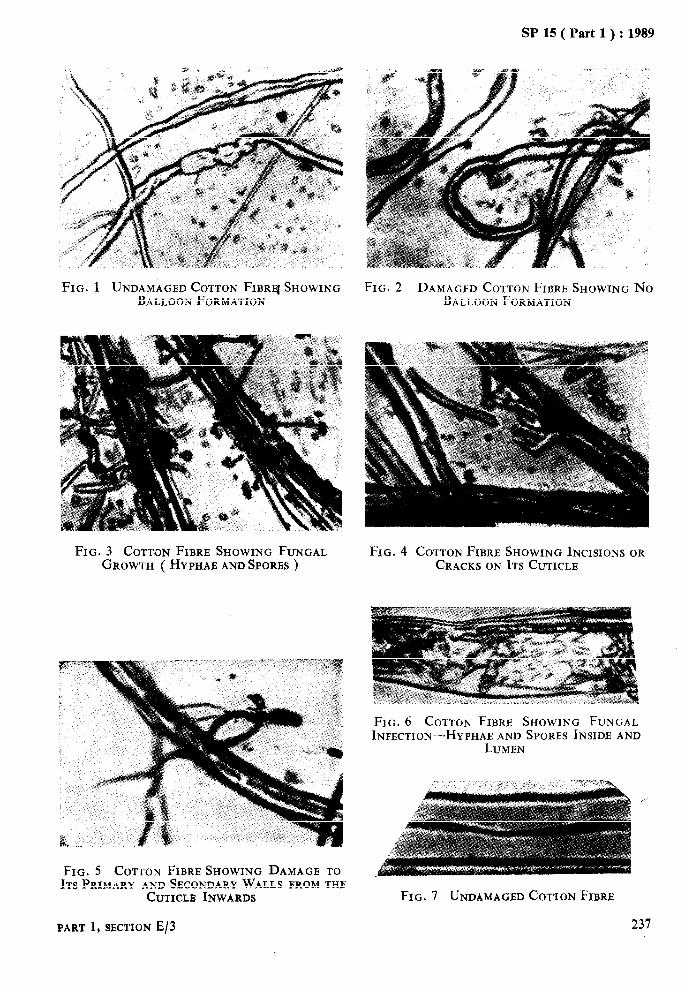
SP 15 ( Part 1 ) : 1989
FIG. 1 UNDAMAGED COTTON FIBREJ SHOWING FIG. 2 DAMAGED COTTON FIBRE SHOWING No BALLOON FORMATION BALLOON FORMATION
FIG. 3 COTTON FIBRE SHOWING FUNGAL FIG. 4 COTTON FIBRE SHOWING INCISIONS OR GROWTH ( HYPHAB AND SPORES ) CRACKS ON JTS CUTICLE
FIG. 5 COTTON FIBRE SHOWING DAMAGE TO ITS PRIMARY AND SECONDARY WALLS FROM THE
CUTIC~_,B INWARDS
FIG. 6 COTTON FIBRE SHOWING FUNGAL INFECTION-HY PHAE AND SPORES INSIDE AND
LUMEN
FIG. 7 UNDAMAGED COTTON FIBRE
PART 1, SJXTfON E/3 237

SP 15 ( Part 1 ) : 1989
FIG. 8 COTTON FIBRE SHOWING MODERATE BACTERIAL DAMAGE
FIG. 9 COTTON FIBRE SHOWING SEVERE BACTERIAL DAMAGE
FIG. 10 UNDAMAGED COTTON FIBRE ( AFTER CONGO-RED TEST >
FIG. 12 COTTON FIBRE SHOWING SEVERE FUNGAL DAMAGE
FIG. 11 COTTON FIBRE SHOWING MODERATE FUNGAL DAMAGE
FIG. 13 COTTON FIBRE SHOWING SEVERE BACTERIAL DAMAGE
238 HANDBOOK OF TEXTILE TESTING
SP 15 ( Part 1 ) : 1989
distilled water to remove the excess of stain. Mount the stained fibres on glass slides and treat them with 18 percent caustic soda solu- tion [ see 3.6 (ii) ] for one minute. Cover the fibres with cover plates and examine them under the microscope with a magnification of 200. Examine five slides and about 500 fibres.
NOTES
1 Damaged fibres will show irregular stain patches, spiral staining and cracks. Severe bacterial damage is indicated by fluffy or fuzzy appearance of the fibres ( see Fig. 10, 11,12and 13 ).
2 Undamaged fibres will show three types of stains depending upon the maturity of the fibres. Immature fibres will show convolutions and pink stains. Half- mature fibres will become faintly red and highly mature fibres will show rupture due to swelling and reveal regular red stain spirals, which should not be mistaken for damaged fibres.
5.1.2 Count separately the number of damaged and undamaged fibres on the slides. Calculate the damage count of the fibres as follows:
Damage count = -.a- x 100 a+b
where a = number of damaged fibres, and b = number of undamaged fibres.
5.1.3 Repeat the procedure prescribed in 5.1.1 and 5.1.2 to determine the damage count of fibres taken from four control specimens drawn as in 2.2.
5.1.4 Compare the damage count values obtain- ed as in 5.1.2 and 5.1.3.
NOTE - Control specimens should have the lower damage count values than the test specimen.
PART 1, SECTION E/3 239

As in the Original Standard, this Page is Intentionally Left Blank

Fc $5 ( Part 1) : 1989
DEa&&MINATION Or KEMP CONTENT’ OF RAW SWBL
( Sozfrce : IS 1348 : 1971 )
Most of the sheep, except the merino and other varies considerably from breed to breed and highly developed breeds, carry two distinct hairy part contains kemp which are opaque, do coats: the outercoat of long, coarse and,wavy not absorb dyes and show very clearly in the hair, and the undercoat of fine crimpy fibres finished fabric. called ‘wool’. The proportion of hair and wool \
1 SCOPE
1.1 This standard prescribes a method for deter- mining the kemp content of raw wool.
2 QUALITY OF REAGENTS
2.1 Unless specified otherwise, pure chemicals shall be used for the purpose of this test and where water is intended to be used as a reagent in this test, only distilled water shall be used.
NOTE - ‘Pure chemicals’ shall mean chemicals that do not contain impurities which affect the test results.
then dry it at a low temperature not exceeding 60°C.
5.2 Condition the test specimen ( see 4.1) and determine the weight correct to one milligram.
5.3 Place the specimen on the velvet board and open it out, bit by bit, using forceps and dissect- ing needle. Separate the kemp fibres. Condition the kemp-free portion to moisture equilibrium ( see 4.1 ) and note its weight correct to one milligram.
3 REAGENTS
3.1 For the purpose of this test, the following reagents shall be used:
a) Benzene or petroleum ether, and b) Sodium oleate solution - 1 percent (w/v).
4 APPARATUS
4.1 For the purpose of this test the following apparatus shall be used:
a) Sampling Frame-Consisting of an adjust- able wooden or metal frame of suitable size and fitted with elastic cords along its length and width ( see Fig. 1 ).
b) Velvet Board - of black or any toher contrasting colour.
c) Pair of Forceps
d) Dissecting Needle
Plan of Sampling Frame Showing
Edges of Wool Sample Evened upto Markers
e) Balance - capable of weighing correct to one milligram.
5 PROCEDURE
5.0 The test shall be carried out in standard atmosphere.
5.1 Take one of the test specimens constituting the test sample and degrease it by treating with benzene or petroleum ether. Evaporate the solvent, treat the specimen in the sodium oleate solution at 40’C for 3 minutes and wash it twice with water. Press the specimen gently between two pads of filter paper to remove water and
I I Table WOOI sompee
Enlarged Section of One Angle Bar of Sampling Frama with Marker and
Wool Sample in Position
FIG. 1 SAMPLING FRAME
PART 1, SECTION E/4 241
1
SP 15 ( Part 1‘ ) : 1989 .j.~ I
6 CALCULATIONS ‘-
6.1 Calculate the kemp content, percent by weight, of the specimen by the following formula:
Kemp content, percent by weight = WI--W, W 1
where ,
W1 c original weight in grams of the specimen ( see 5.2 ), and
i W, - weight in grams of the kemp-free
specimen ( see 5.3 ).
6.2 Take at least two more readings and deter- mine the average of all the values.
7 REPORT
7.1 The test report shall include the following information:,
a) Kemp content, percent b) Number of tests.
242 HANDBOOK OF TEXTILE TESTING

SP ts ( Part 1 ) : 1989
DETERMINATION OF CLEAN FIBRE AND VEGETABLE MATTER CONTENT AND SCOURING YIELD OF RAW WOOL
( Source : IS
Raw wool, that is, wool as shorn from the sheep or wool which is pulled, limed or ginned and carded, contains varying amount of impurities like sand, grease, suint, vegetable mltter, tags
1349 : 1964)
and dung. It: is, therefore, purchased on the basis of either laboratory scoured yield or clean wool fibre content.
1 SCOPE
1.1 This standard prescribes methods for deter- mination of clean wool fibre content and laboratory scouring yield of raw wool.
2 QUALITY OF REAGENTS
2.~ Unless otherwise specified, pure chemicals shall be used for the purpose of this test.
NOTE - ‘Pure chemicals’ shall mean chemicals that do not contain impurities which affect the test results.
3 REAGENTS
3.1 Scouring Solution
3.1.1 Standard Scouring Solution
containing 3 g of anhydrous sodium carbonate and one gram of neutral soap per litre of water ( see Note ).
OR
3.1.2 Except in case of dispute any of the com- tiercially available wool-scouring solution of ihe soda-ash plus-nonionic synthetic detergent type may be used.
NOTE - Soft water having hardness not more t3an 60 parts per million should bz used.
3.2 Neutral Alcohol
95 percent.
3.3 Sodium Hydroxide Solution
10 percent ( W/Y ).
3.4 Dilute Acetic Acid
0.1 percent ( v/v).
4 APPARATUS
4.1 Tubs
minimum 4, each of at least 50 litres capacity.
4.2 Basket
made of copper or stainless steel with the bottom made of wire cloth of the kind prescrib- ed to be used for l-00-mm IS Sieve,
PART 1, SECTION E/5
4.3 Wringer or Hydroextractor
4.4 Balance
capable of weighing to an accuracy of O-5 g.
4.5 Drying Oven
ventilated type, capable of maintaining an inside temperature of 105 & 2°C and provided with a balance capable of weighing to an accuracy of 0.5 g; the balance shall have one of its pans in
#the form of wire-cage suspended within the oven.
4.6 Soxhlet Extractor
4.7 Muffle Furnace
capable of maintaining an inside temperature of 700 f 20°C.
5 PROCEDURE 5.1 Take a sealed container. If its label indicates the original weight of the test specimen contain- ed therein, take-the test specimen out and note its original weight ( W, ). If the label of the container does not indicate the weight of the specimen contained therein, weigh the sealed container, remove the test specimen out of it, re-weigh the container, and from the difference between the two weighings, determine the origi- nal weight ( W1 ) of the test specimen. Open out the specimen either by hand or by mechanicai means and free it from impurities like dirt, dung, strings, etc, avoiding any loss of fibre and vegetable matter. Heat the scouring solution to 52 f 5°C and fill three tubs with it. Ratio of wool weight to volume of solution used for scouring bath shall be less than 15 g per litre. Agitate the specimen (enclosed ina 40 mesh net bag ) in the basket for 3 to 5 minutes with hands. Use rubber glov& ( alkali proof) for agitation. Remove the’mesh bag,with the speci- men and squeeze between the rollers of wringers before it is passed on to the next tub. Treat the specimen ( see Note ) similarly in the second and third tub. Fill the fourth tub with soft water and heat to 52 f 5°C and rinse the speci- men in it. Remove the specimen and spray it with a strong stream of warm water so as to flush out, as much as possible, sand and other soil, pass the specimen through the rollers of
243

wringers and centrifuge for five minutes to remove the excess of water. Dry the specimen in drying oven at 105 & 2°C to constant weight. Note the oven-dry weight ( W2 ) of the specimen accurately. Preserve the oven-dry specimen.
NOTE - After scouring in each bowl, recover the fibre lost during scouring by floatation and add the recovered fibres to the original sample before drying.
5.1.1 Repeat the procedure with the remaining specimens.
5.2 Alcohol Extractable Matter
Determine the alcohol extractable matter con- tent of the oven-dry scoured specimen by the following method.
5.2.1 Take about 10 g of scoured oven-dry specimen ( see 5.1). Re-dry it in a drying oven at 105 &- 2°C cool in a desiccator and weigh. Extract it with neutral alcohol in a Soxhlet extractor by heating on a water-bath for 20 extractions. Cool and disconnect the extraction flask. Recover bulk of the alcohol by distilla: tion and evaporate the residue to dryness by drying it to constant weight in the drying oven at 105 f 2°C.
NOTE - Owing to the slight volatility of certain constituents of the extract and to other causes, abso- iute constancy of weight is seldom attained. Prolong- ed heating is, therefore, uudesirable. The weight may usually be regarded as constant if the loss between the two successive weighings taken at an interval of 30 minutes does not exceed 0’1 percent of the first of the two values.
5.2.2 Calculate the per&ntage of alcohol extractable matter content by the following formula:
IOOU X=-
where
X = alcohol extractable matter content, percent, by weight;
a = weight, in g, of the residue; and b i: weight, in g, of the oven-dry speci-
men taken.
5.3 Ash Content
Determine the.ash content of scoured oven-dry specimen by the following method.
5.3.1 Take at least 5 g of scoured oven-dry specimen (see 5.1). Place it in a .tared vitreous silica dish and re-dry it in a drying oven at 105 &- 2°C. Cool in a desiccator and weigh. Slowly ignite the specimen in the dish over a bunsen burner till the specimen gets charred and ceases to produce volatile matter. Transfer the dish to a muffle furnace, maintained at 700 -L 2O”C!, ash the charred specimen and keep it wzhin the furnace for one hour or more till it attains constant weight.
5.3.2 Calculate the percentage of ash content by the following formula:
100a z- 7
where
z = ash content, percent, by weight; a = weight, in g, of ash; and b = weight, in g, of the oven-dry speci-
men taken.
5.4 Vegetable Matter Content
Determine the vegetable matter content of the oven-dry scoured specimen by the following method.
5.4.1 From each of the scoured oven-dry speci- mens ( see 5.1) take approximately equal quan- tities of wool, so as to make about 40 g. Re-dry it in the drying oven at 105 f 2°C for such period till two consecutive weighings do not differ by more than 0.1 percent.
5.4.2 Take 400 ml of sodium hydroxide solution of 10 percent concentration in a beaker and bring it to the boil. Transfer the oven-dried wool to the beaker and boil for 3 minutes stirring the contents all the time. Allow to settle and decant through a 125-micron IS Sieve. Add 100 ml of cold water to the beaker and transfer the residue to the sieve. Wash the residue thoroughly with distilled water and rinse with dilute acetic acid to remove last traces of alkali. Wash finally with distilled water until the filtrate is neutral to litmus paper. Remove with the help of a tweezer, all vegetable fibres and tag material from the residue. Transfer the residue to a porcelain dish or cr_udble and dry it at 105 f 2°C for such period till two consecutive weighings do not differ by more than 0.1 percent.
5.4.3 Calculate the vegetable matter content, percent, in the sample by the following formula:
V = axFx100
b where
V-
Q=
F X
b=
vegetable matter content, percent, of the oven-dry scoured specimen; oven-dry weight, in g, of the resi- due; the correction factor taken to be equal to 1.1; and oven-dry weight, in g, of the speci- men ( see 5.4.1 ).
5.5 Calculation
5.5.1 Calculate the clean wool fibre content of the sample by the following formula:
FA WBX[ loo-(X+Z+V)]
0.842 WI
244 HANDBOOK OF TEXTILE TESTING

SP 15 ( Part 1) : 1989
where
F = clean wool fibre content, percent, of the sample;
Ws = oven-dry weight., in g, of the speci- men after scouring ( see 5.1);
x= alcohol extractable matter content, percent, of the scoured oven-dry specimen ( see 5.2 );
2 = ash content, percent, of the scour- ed oven-dry specimen ( see 5.3 );
V = vegetable matter content, percent, of the scoured oven-dry specimen ( see 5.4 ); and
WI = original weight, in g, of the speci- men ( see 5.1 ).
5.5.2 Calculate the vegetable matter content, percent, in the sample by the following formula:
wzxv VI = 0.842 WI
where
VI - vegetable matter content, percent, in the sample adjusted to standard condition ( see Note );
w2. = oven-dry weight, in g, of the speci- men after scouring ( see 5.1);
V = vegetable matter content, percent, of the scoured oven-dry specimen ( see 5.4 ); and
w, = original weight, in g, of the speci- men ( see 5.1).
NOTE - The standard condition for wool shall be a moisture content of 13’8 percent, an alcohol extract- able matter content of 1’5 percent, and an ash content of 0’5 percent.
5.5.3 Calculate the laboratory scouring yield of the sample by the following formula:
L=F+V,
where
L = laboratory scouring yield, percent, of the sample;
F = clean wool fibre content, percent, of the sample ( see 5.5.1 ); and
v, = vegetable matter content, percent, in the sample adjusted to standard condition ( see 5.5.2 ).
5.6 Calculate in a similar manner ( see 5.5.1, 5.5.2 and 5.5.3 ) the clean wool fibre content, percent, and the laboratory scouring yield, percent, of the remaining test specimens. If the difference between any two of the three values for each characteristic exceeds 2.5 percent, draw fresh specimens in lieu thereof and test them. Calculate the respective mean of the values, separately for clean wool fibre content, percent, and laboratory scouring yield content.
6 REPORT
The report shall include the following informa- tion:
a) b) c)
Clean wool fibre content, percent; Laboratory scoured yield, percent; and Vegetable matter content, percent.
PART 1, SBCTION E/5 245

As in the Original Standard, this Page is Intentionally Left Blank
SP 15 ( Part 1) : 1989
DETERMINATION OF SOLUBILITY OF WOOL IN ALKALI
’ ( Source : IS
The solubility of wool in alkali provides a useful index of the extent of the change in its chemi- cal properties brought about by certain agencies. Wool, when treated with acids, oxidi- zing or reducing agents, or when exposed to heat or light, increases in solubility, whereas when treated with mild alkali, which IS normally used in processing, or when treated with cross- linking agents, decreases in solubility. The solubility of wool depends on the severity of the treatment. This methcd of test is most useful
3429 : 1966 )
when an untreated control sample is available and when the nature of treatment of the sample under test is known. This method is useful as a control in processing. When the sample has been treated by two different agencies having opposite effects on the solubility, the interpreta- tion of the results, even when an untreated control sample is available, is difficult and other tests are necessary to supplement the information.
1 SCOPE 4.2 Acetic Acid Solution
1.1 This standard prescribes a method for deter- mining the solubility of wool in alkali, applica- ble to all-wool textiles in any form such as fibr’ e,
prepared by dissolving 10 ml of glacial acetic acid in sufficient amount of water and made up to 1 litre.
yarn and fabrics.
2 PRINCIPLE
2.1 A sample is immersed in 0.1 N sodium hydroxide solution under specified conditions of time, temperature and volume. The loss in weight is determined as the difference between the dry weights of the sample before and after treatment.
3 APPARATUS
3.1 Water-Bath
capable of maintaining a temperature of 66 f 05°C.
3.2 Stoppered Conical Flasks
of 250 ml capacity.
3.3 Sintered-Glass Filtering Crucibles
of 30 ml capacity with a pore size of 90 to ‘150 microns and provided with ground-glass stop- pers. If stopper is not available, the crucible should be covered with a watch-glass during cooling and weighing.
4 REAGENTS
4.0 Quality of Reagents
Unless specified otherwise, pure chemicals shall be employed in tests and distilled water shall be used wherever the use of water as a reagent is intended.
NOTE - ‘Pure chemicals’ shall mean chemicals that do not contain impurities which affect the experi- mental results.
4.1 Sodium Hydroxide Solution
0.1 N.
PART 1, SECTION E/6
4.3 Light Petroleum
boiling range between 40 and 60°C.
5 PREPARATION OF TEST SPECIMENS
5.1 From the test sample, take a representative sample ( about 10 g ) sufficient to provide fat and burr-free wool for the following test speci- mens:
a) One test specimen weighing 1-O g for determining the dry weight ( see 6.1 );
b) Two test specimens, each weighing 1-O g, for the solub ility test (see 6.2.1 and 6.3 ); and
c) Two test specimens each weighing 2-O g for determining the acid content ( see A-2.1 ).
NOTE - The representative samole should be disin- tegrated and &t into shorter Ikgths of one centi- metre. The sample should be brought to room tem- perature.
5.2 Extract the representative sample in a Soxhlet apparatus with light petroleum for one hour at a minimum rate of six extractions per hour. Allow the petroleum to evaporate and remove the vegetable and other foreign matter by hand picking.
6 PROCEDURE
6.1 From the extracted representative sample, take one test specimen weighing 1.0 g. Dry it in a weighing bottle at 105 f 3°C for three hours. Stopper the bottle and cool it in a desic- cator and weigh. Remove the test specimen and weigh the weighing bottle and calculale the dry weight of the test specimen.
247

SP 15 ( Pa@ 1) : 1989
6.2 Pour 100 ml of sodium hydroxide solution into a flask. Stopper it loosely and fix it in the water-bath by any suitable means, so that the level of the water outside the flask is at least 2 cm higher than the level of the solution inside.
NOTE - This procedure is essential for precise con- trol of temperature.
6.2.1 When the temperature of the sodium hydroxide solution reaches 65 I, 0*5”C, intro- duce carefully one test specimen ‘weighing 1.0 g into the flask. Replace the stopper tightly. Shake the flask gently to ensure complete wetting of the specimen and replace it in the water-bath. Again shake the flask gently after 15, 30 and 45 minutes, the time of shaking not to exceed 5 minutes. Continue the reaction for 60 minutes. Transfer the contents of the flask to a weighed filtering crucible, at the same time drain the crucible by suction. Wash the flask with distilled water and collect the washings in the filtering crucible. Wash the residue in the crucible six times with water, draining comple- tely between each wash. Fill the crucible twice successively with acetic acid solution. Allow it to stand for one minute and drain the crucible by suction. Wash the residue six times with distilled water draining completely between each wash. Dry the crucible and the contents at 105 f 3°C for three hours. Stopper the crucible or cover it with a watch glass. Cool it in a desiccator and weigh. Repeat the operations of drying and weighing until constant weight is obtained.
6.3 Repeat the procedure prescribed in 6.2 and 6.2.1 with one more test specimen weighing 1.0 g.
6.4 From the representative sample ( see 5.1) take about 1 g of test specimen. Extract it with cold water with a liquor to material ratio of 50 : 1 for half an hour shaking the flask occasi- onally and determine the pH of the extract. If the pH of the water extract is less than 4.0, determine the acid content by the method given in Annex A.
7 CALCULATION
7.1 Calculate the alkali solubility of wool as the loss in weight of the test specimen, expressed
as a percentage of its calculated dry, fat and acid free weight by the formula given in 7.1.1 or 7.1.2.
7.1.1 If the sample does not contain acid ( that is, if the pH is 4-O or greater than 4.0 ) calculate the alkali solubility of each test specimen by the following formula:
s= !!y!L x 100 I
where
S E solubility in alkali, percent;
W, = dry weight of the test specimen ( see 6.1 ); and
w, - dry weight of the residue ( see 6.2.1 ).
7.1.1.1 Calculate the average of the two results obtained as in 7.1.1.
7.1.2 If the sample contains acid ( that is, if pH is less than 4.0 ), calculate the alkali solubi- lii;m;[aeach test specimen by the following
S- 100 100 W’&W - a)
( 100 - Q
where
s = solubility in alkali, percent:
WI = dry weight of the test specimen ( see 6.1);
We = dry weight of the residue ( see 6.2.1); and
a = percentage of acid ( see A-3.2 ).
7.1.2.1 Calculate the average of the two results obtained as in 7.1.2.
8 REPORT
The report shall include the following infor- mation:
a) Type of material, and
b) Alkali solubility, percent.
248 HANDBOOK OF TEXTILE TESTING

SP 15 ( Part 1 ) : 1989
ANNEX A ( Clause 6.4 )
METHOD FOR DETERMINING THE ACID CONTENT
A-l REAGENTS
A-l.1 Pyridine Solution
prepared by dissolving 5 g of pyridine in one litre of distilled water.
A-l.2 Sodium Hydroxide Solution
0.1 N.
NOTE- This solution should be standardized by titration with standard potassium hydrogen phthalate solution.
A-I.3 Phenolphthalein Indicator
prepared by dissolving 0.5 g of in 95 ml of ethyl alcohol and water..
J
A-2 PROCEDURE
phenolphthalein 5 ml of distilled
A-2.1 Place two test specimens each weighing 2 g in separate glass-stoppered conical flasks. Pour 100 ml of pyridine solution into each flask. Stopper the flasks and shake mechanically for one hour or allow the flasks to stand overnight after initial shaking to ensure complete wetting of the specimens. Decant the liquid from the wool, filtering through a plug of glass wool to retain fibrous material. Pipette out 50 ml of each filtrate in separate conical flasks. Add three drops of phenolphthalein indicator to each flask and titrate separately with 0.1 N
sodium hydroxide till a faint or a light pink colour appears.
A-3 CALCULATIONS
A-3.1 Calculate the weight of acid as the per- centage of the dry weight of each specimen by the following formula:
vxkxn a=
Wl
where
a E
,’ =
k =
n E
acid content, percent; volume, in ml, of O-1 N sodium hydroxide solution required to neutralize 50 ml of pyridine extract; .
constant ( see Note ); normality of the sodium hydro- xide solution; and
W, = dry weight of 1 g specimen ( see 6.1 ).
NOTE - The constant has the following values:
Acid Value Sulphuric acid 4’9 Formic acid 4’6 Acetic acid 6’0
A-3.2 Calculate the average of the values obtained as in A-3.1.
PART 1, SECTION E/6 249

As in the Original Standard, this Page is Intentionally Left Blank
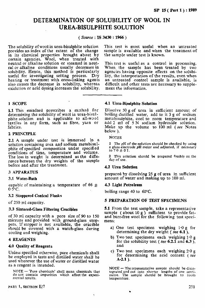
SP 15 ( Part 1) : 1989
DETERM1NATION OF SOLUBILITY OF WOOL IN UREA-BISULPHITE SOLUTION
( Source : IS 3430 : 1966 )
The solubility of wool in urea-bisulphite solution provides an index of the extent of the change in its chemical properties brought about by certain agencies. Wool, when treated with neutral or alkaline solution or steamed in neut- ral or alkaline conditions usually decreases in solubility. Hence, this method is particularly useful for investigating setting process. Dry heating or treatment with cross-linking agents also causes the decrease in solubility, whereas oxidation or acid dyeing increases the solubility.
This test is most useful when an untreated sample is available and when the treatment of the sample under test is known.
This test is useful as a control in processing. When the sample has been treated by two agencies having opposite effects on the solubi- lity, the interpretation of the results, even when an untreated control sample is available, is difficult and other tests are necessary to supple- ment the information.
1 SCOPE
1.1 This standard prescribes a method for determining the solubility of wool in urea-bisul- phite solut~n and is applicable to all-wool textiles in any form, such as fibre, yarn or fabrics.
2 PRINCIPLE
2.1 A sample under test is immersed in a solution containing urea and sodium metabisul- phite of specified composition under specified conditions of time, temperature and volume. The loss in weight is determined as the diffe- rence between the dry weights of the sample before and after the treatment.
3 APPARATUS
3.1 Water-Bath
capable of maintaining a temperature of 66 f 0.5%.
3.2 Stoppered Conical Flasks
of 250 ml capacity.
3.3 Sintered-Glass Filtering Crucibles
of 30 ml capacity with a pore size of 90 to 150 microns and provided with ground-glass stop- pers. If stopper is not available, the crucible should be covered with a watch-glass during cooling and weighing.
4 REAGENTS
4.0 Quality of Reagents
Unless specified otherwise, pure chemicals shall be employed in tests and distilled water shall be used wherever the use of water or distilled water as a reagent is intended.
NOTE - ‘Pure chemicals’ shall mean chemicals that do not contain impurities which affect the experi- mental results.
PART 1, SECTION E/7
4.1 Urea-Bisulphite Solution
Dissolve 50 g of urea in sufficient amount of boiling distilled water, add to it 3 g of sodium metabisulphite, cool to room temperature and add 2 ml of 5 N sodium hydroxide solution. Make up the volume to 100 ml (see Notes below ).
EMOTES
1 The pH of the solution should be checked by using a glass electrode pH meter and adjusted, if necessary to 7’0 f 0’1.
2 This solution should be prepared freshly on the day of use.
4.2 Urea Solution
prepared by dissolving 25 g of urea in suflicient amount of water and making up to 100 ml.
4.3 Light Petroleum
boiling range 40 to 60°C.
5 PREPARATION OF TEST SPECIMENS
5.1 From the test sample, take a representative sample ( about 10 g ) su&ient to provide fat- and burr-free wool for the following test speci- mens:
4
‘3
c)
One test specimen weighing 1-O g for determining the dry weight ( see 6.1), Two test spe$mens each weighing 1-O g fidthe solubllrty test ( see 6.2.1 and 6.3 ),
Two test specimens each weighing 2-O g for determining the acid content ( see A-2.1 ).
NOTE - The representative sample should be disin- tegrated and cut into shorter lengths of one centi- metre. The sample should be brought to room temperature.
251 .

SP 15 ( Part 1) : 1989
5.2 Extract the representative sample in a Soxhlet apparatus with light petroleum for one hour at a minimum rate of six extractions per hour. Allow the petroleum to evaporate and remove the vegetable and other ~foreign matter by hand picking.
6 PROCEDURE
6.1 From the extracted representative sample, take one test specimen weighing 1-O g. Dry it in a weighing bottle at 105 f 3°C for three hours. Stopper the bottle and cool it in a desiccator and weigh. Remove the test specimen, weigh the weighing bottle and calculate the dry weight of the test specimen.
6.2 Pour 100 ml of urea-bisulphite solution into a flask. Stopper loosely and fix the flask in the water-bath by any suitable means so that the level of the water outside the flask is at least 2 cm higher than the level of the solution inside.
NOTE - This procedure is essential for precise COD trol of temperature.
6.2.1 When the temperature of urea-bisulphite solution reaches 65 f 0*5”C, introduce one test specimen weighing 1.0 g into the flask. Replace the stopper tightly and shake the flask gently to ensure complete wetting of the test specimen and replace it in the water-bath. Again shake the flask gently after l5, 30 and 45 minutes, the time of shaking not to exceed 5 minutes. Continue the reaction for 60 minutes. Transfer the contents of the flask to a weighed filtering crucible and drain the crucible by suction. Wash any fibrous material remaining in the Aask into the crucible. Wash the residue in the crucible three times with urea solution ( 10 ml each time) and afterwards six times with distill- ed water, every-time allowing the liquid to stand in contact with the residue for about 15 seconds before applying suction to drain com- pletely. Dry the crucible and the contents at 105 f 3°C for three hours. Stopper the crucible or cover it with a watch-glass. Cool it in a desiccator and weigh. Repeat the operation of drying and weighing until constant weight is obtained.
6.3 Repeat the procedure prescribed in 6.2 and 6.2.1 with one more test specimen weighing 1.0 g.
6.4 From the representative sample ( see 5.1) take about 1 g of test specimen. Extract it with cold water with a liquor to material ratio of 50 : 1 for half an hour shaking the flask occa- sionally and determine the pH of the extract. If
the pH of the water extract is less than 4.0, determine the acid content by the method given in Annex A.
7 CALCULATION
7.1 Calculate the urea-bisulphite solubility of wool as the loss in weight of the test specimen, expressed as a percentage of its calculated dry, fat and acid free weight by the formula given in 7.1.1 or 7.1.2.
7.1.1 If the sample does not contain acid ( that is if the pH is 4-O or greater than 4-O ) calculate the urea-bisulphite solubility of each test speci- men by the following formula:
where
S - solubility in urea-bisulphite, per- cent;
WI = dry weight of the specimen ( see 6.1 ); and
w, - dry weight of the residue ( see 6.2.1 ).
7.1.1.1 Calculate the average of the two results obtained as in 7.1.1.
7.1.2 If the sample contains acid ( that is if yH is less than 4.0 ), calculate the urea-bisulphite solubility of each test specimen by the following formula:
S= 100 (100 w,wwz -u)
( 100 -“, )
where
S = solubility in urea-bisulphite, per- cent;
w1 - dry weight of the specimen ( see 8.1);
W 2 = dry weight of the residue (see 6.2.1);
a content of acid, percent (see = A-3.2 ).
7.1.2.1 Calculate the average of the two results obtained as in 7.1.2.
8 -REPORT
The report shall include the following information:
a) Type of material, and b) Urea-bisulphite solubility, percent.
252 HANDBOOK OF TEXTILE TESTING
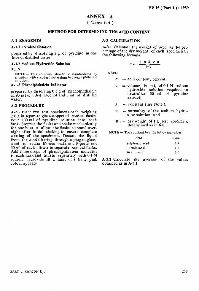
SP 15 ( Part 1 ) : 1989
ANNEX A ( Clause 6.4 )
METHOD FOR DETERMINING THE ACID CONTENT
A-l REAGENTS
A-l.1 Pyridine Solution
prepared by dissolving 5 g of pyridine in one litre of distilled water.
A-l.2 Sodium Hydroxide Solution 0.1 N.
NOTE -This solution should be standardized by titration with standard potassium hydrogen phthalate solution.
A-l.3 Phenolphthalein Indicator
prepared by dissolving 0.5 g of phenolphthalein in 95 ml of ethyl alcohol and 5 ml of distilled water.
A-2 PROCEDURE
A-2.1 Place two test specimens each weighing 2.0 g in separate glass-stoppered conical flasks. Pour 100 ml of pyridine solution into each flask. Stopper the flasks and shake mechanically for one hour or allow the flasks to stand over- night after initial shaking to ensure complete wetting of the specimens. Decant the liquid from the wool filtering through a plug of glass- wool to retain fibrous material. Pipette out 50 ml of each filtrate in separate conical flasks. Add three drops of phenolphthalein indicator to each flask and titrate separately with 0.1 N sodium hydroxide till a faint or a light pink colour appears.
A-3 CALCULATION -
A-3.1 Calculate the weight of acid as the per- centage of the dry weight of each specimen by the following formula:
vxkxn U=
WI
where
a 5
V 5
k =
n =
w, =
acid content, percent;
volume! in ml, of @l N sodium hydroxide solution required to neutralize 50 ml of pyridine extract;
constant ( see Note );
normality of the sodium hydro- xide solution; and
dry weight of 1 g test specimen, determined as in 6.1.
NOTE - The constant has the following values:
Acid Value
Sulphuric acid 4’9 Formic acid 4’6 Acetic acid 6’0
A-3.2 Calculate the average of the values obtained as in A-3.1.
PART 1, SECTION E/7 253

As in the Original Standard, this Page is Intentionally Left Blank

SPlS(Part1):1989
DETERMINATION OF WOOL CONTENT IN WOOLLEN TEXTILE MATERIALS
(Source: IS 8476:1977)
This method determines the total protein con- A reference to IS : 1793-1973 ‘Guide for mark- tent in the woollen textiles materials. However, ing textile materials made of wool (first it does not necessarily mean that the protein content so determined is ‘all wool’. It may also
revision )’ may be made for definitions of textile
contain other protein fibres besides ‘wool’. materials containing wool.
1 SCOPE
1.1 This standard prescribes a method for determination of percentage of wool in all-wool textiles in any form, such as fibre, yarn, fabrics, druggets and carpets.
2 PRINCIPLE
2.1 A pretreated specimen of known oven-dry mass is dissolved in sodium or potassium hydro- xide. The non-wool content, including burrs, seeds, etc, is oven-dried and weighed, and percentage of wool content is calculated there- from.
3 APPARATUS
3.1 Sorhlet Apparatus
3.2 Sintered Glass Crucible No. 1
3.3 Desiccator
3.4 Weighing Balance
capable of weighing to an accuracy of 10 mg.
3.5 Drying Oven
capable of maintaining 105 f 3°C and preferably balance.
4 REAGENTS
4.0 Quality of Reagents
a temperature of fitted with weighing
Unless specified otherwise pure chemicals shall be employed in test and distilled water shall be used wherever the use of water as a reagent is intended.
NOTE - ‘Pure chemicals’ shall mean chemicals that do not contain impurities which affect the test results.
4.1 Sodium or Potassium Hydroxide Solution
5 percent ( m/v ).
4.2 Benzene-Methyl Alcohol Mixture
(3:2).
4.3 Acetic Acid Solution
3 percent ( v/v ).
PART 1, SECTION E/8
5 PREPARATION OF TEST SAMPLE
5.1 Take the sample cut it into pieces, if
weighing about 30 g and necessary. Put it in the
Soxhlet apparatus and extract with benzene- methyl alcohol mixture for two hours at a minimum rate of six cycles per hour. Allow the solvent to evaporate and then wash the sample in water ( about 500 ml ) at 50°C for 30 minutes.
6 PROCEDURE 6.1 Take a representative specimen weighing about 5 g from the prepared sample and place it in a suitable container. Place the specimen in the drying oven maintained at a temperature of 105 f 3°C and dry it to a constant mass.
NOTE - The mass shall be taken as constant when the difference between the two successive weighings made at intervals of 20 minutes is less than 0’05 percent.
6.2 Determine the mass of the specimen with- out removing it from the oven. In case the drying oven is not provided with the weighing balance, remove the specimen from the oven and transfer it to a weighing container of known mass provided with a tight lid. The transference of the specimen shall be done in as less a time as possible. Cool the specimen and the container in a desiccator to room tem- perature before weighing. Weigh the container and determine the mass of the specimen to an accuracy of 10 mg. 6.3 Put the specimen in a beaker together with 500 ml of 5 percent sodium or potassium hydro- xide solution and boil slowly until the wool fibres dissolve. After 10 minutes of boiling, filter through a sintered glass crucible. Wash the residue first with warm water, then with acetic acid solution and finally with hot water. Dry the residue at 105 1 3°C.
6.4 Examine carefully the residue and the pores of the crucible for incompletely dissolved wool. If it is present dissolve it by pouring sodium or potassium hydroxide solution. Rinse and dry the residue at 105 & 3°C to constant mass ( see Note under 6.1) and weigh it to an accuracy of 10 mg.
255
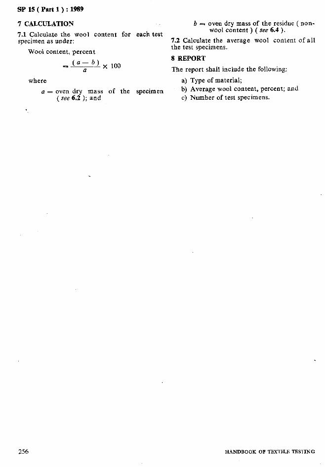
SP 15 ( Part 1) : 1989
7 CALCULATION
7.1 Calculate the wool content for each test specimen as under:
Wool content, percent
_ (a--b) a
where
x 100
a = oven dry mass of the specimen ( see 6.2 ); and
b E oven dry mass of the residue ( non- wool content ) ( see 6.4 ).
7.2 Calculate the average wool content of all the test specimens.
8 REPORT
The report shall include the following:
a) Type of material; b) Average wool content, percent; and c) Number of test specimens.
256 HANDBOOK OF TEXTILE TESTING
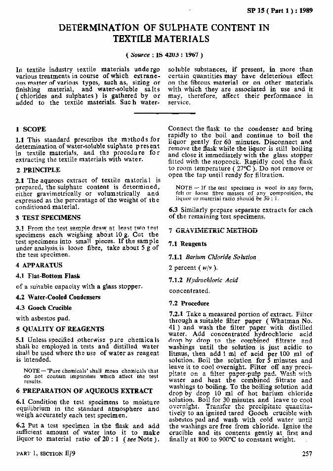
SP 15 ( Part 1) : 1989
DETERMINATION OF SULPHATE CONTENT IN TEXTILE MATERIALS
( Source : IS
In textile industry textile materials undergo various treatments in course of which extrane- ous matter of various types, such as, sizing or finishing material, and water-soluble sa Its ( chlorides and sulphates ) is gathered by or added to the textile materials. Sue h water-
4203 : 1967 )
soluble substances, if present, in more than certain quantities may have deleterious effect on the fibrous material or on other materials with which they are associated in use and it may, therefore, affect their performance in service.
1 SCOPE
1.1 This standard prescribes the methods for determination of water-soluble sulphate present in textile materials, and the procedure for extracting the textile materials with water.
2 PRINCIPLE
2.1 The aqueous extract of textile material is prepared, the sulphate content is determined, either gravimetrically or volum:trically and expressed as the percentage of the weight of the conditioned material.
3 TEST’SPECIMENS
3.1 From the test sample draw at least two test specimens each weighing about 10 g. Cut the test specimens into small pieces. If the sample under analysis,is loose fibre, take about 5 g of the test specimen.
4 APPARATUS
4.31 Flat-Bottom Flask
of a suitable capacity with a glass stopper.
4.2 Water-Cooled Condensers
4.3 Gooch Crucible
with asbestos pad.
5 QUALITY OF REAGENTS
5.1 Unless specified *otherwise plre chemica 1s shall be employed in tests and distilled water shall be used where the use of water as reagent is intended.
NOTE - ‘Pure chemicals’ shall msan chemicals that :‘,“,,Et contain impurities which affect the test
6 PREPARATION OF AQUEOUS EXTRACT
6.1 Condition the test specimens to moisture equilibrium in the standard atmosphere and weigh accurately each test specimen.
6.2 Put a test specimen in the flask and add sufficient amount of water into it to make liquor to material ratio of 20 : 1 ( see Note ) ,
PART 1, SECTION E/9
Connect the flask to the condenser and bring rapidly to the boil and continue to boil the liquor gently for 60 minutes. Disconnect and remove the flask while the liquor is still boiling and close it immediately with the glass stopper fitted with the stopcock. Rapidly cool the flask to room temperature ( 27°C ). Do not remove or open the tap until ready for filtration.
NOTE - If the test specimen is wool in any form, felt or loose fibre masses of any composition, the liquor to material ratio should be 50 : 1.
6.3 Similarly prepare separate extracts for each of the remaining test specimens.
7 GRAVIMETRIC METHOD
7.1 Reagents
7.1.1 Barium Chloride Solution
2 percent ( w/v ).
7.1.2 Hydrochloric Acid
concentrated.
7.2 Procedure
7.2.1 Take a measured portion of extract. Filter through a suitable filter paper ( Whatman No. 41 ) and wash the filter paper with distilled water. Add concentrated hydrochloric acid drop by drop to the combined filtrate and washings until the solution is just acidic to litmus, then add 1 ml of acid per 100 ml of solution. Boil the solution for 5 minutes and leave it to cool overnight. Filter off any preci- pitate on a filter paper-pulp pad. Wash with water and heat the combined filtrate and washings to boiling. To the boiling solution add drop by drop 10 ml of hot barium chloride solution. Boil for 30 minutes and leave to cool overnight. Transfer the precipitate quantita- tively to an ignited tared Gooch crucible with asbestos pad and wash with cold water until the washings are free from chloride. Ignite the crucible and its contents gently at first and finally at 800 to 900°C to constant weight.
257

7.2.2 Carry out the blank determination.
7.2.3 Calculate the percentage of water-soluble sulphate by either of the following formulae:
a) For all materials in yarn and fabric form other than wool ( see Note 1 ):
P_ 823 x (a-b) - V
b) For wool in any textile form and for felts and loose fibre masses of any composition ( see Note 2 ):
p= 2058 x (a--bj
V
where
P = percentage, by weight, of water- soluble sulphates as sulphate ion;
a = weight, in g, of the precipitate obtained in the test ( see 7.2.1 );
b = weight, in g, of the precipitate ;r;ined as in blank ( see 7.2.2 );
V = volume, in ml, of extract taken for the test.
NOTES
1 100 ml of extract are equivalent to 5’0 g of condi- tioned test specimen.
2 100 ml of extract are equivalent to 2’0 g of condi- tioned test specimen.
7.2.4 Repeat the test with the extracts of the remaining test specimens and calculate the per- centage of water-soluble sulphate in each test specimen.
7.2.5 Calculate the average of the , values obtained as in 7.2.3 and 7.2.4.
8 VOLUMETRIC METHOD
8.1 Reagents
8.1.1 Benzidine Hydrochloride Solution
prepared as follows:
Dissolve 5 g of benzidine hydrochloride in 40 ml of 1 N hydrochloric acid and dilute the solution to 250 ml with 50 percent aqueous ethanol ( v/v ). Heat the solution to boil, cool, filter if necessary, and store in a dark glass stoppered bottle.
8.1.2 Alcohol
95 percent ( v/v )
8.1.3 Standard Sodium Hydroxide Solution
O-02 N.
8.1.4 Standard Sulphuric Acid
O-02 N.
8.1.5 Phenol Red Indicator
O-25 percent ( w/v ) prepared in 25 percent ethanol ( v/v ).
8.2 Procedure
8.2.1 Take a measured portion of extract ( see 6.2 ) and concentrate it to 20 ml. Add to this 20 ml of alcohol followed by 20 ml of benzidine hydrochloride solution. Allow the solution to stand for 30 minutes. Filter the solution under low suction through a suitable filter paper ( Whatman N’o. 42 ). Wash the precipitate with 5 ml of alcohol and repeat the wasliing 4 times more. After the test washing transfer the precipitate and filter paper to 250- ml conical flask and add 25 ml of distilled water. Add few drops of phenol red indicator. Heat the solution to boiling and cool. Add a known volume of standard sodium hydroxide solution to the contents of the flask, shake thoroughly to dissolve all the precipitate, add more phenol red indicator as required and back titrate the excess of sodium hydroxide with standard sulphuric acid.
NOTE - The accuracy of the above method may be checked by determining the sulphur content in 2 ml of sodium sulphate solution of known strength. 2 ml of sodium sulphate solution is taken in a beaker and 8 ml of alcohol is added. To this 4 ml of benzidine hydrochloride is added. The solution is allowed to stand for 30minutes. The precipitate is filtered and titrated against 0’02 N sodium hydroxide as above.
8.2.2 Calculate the percentage of water-soluble sulphates by either of the following formulae:
a>
b)
For all materials in yarn and fabric form, other than wool ( see Note 1 ):
P = A x B x 4.8 x 2. V
For wool in any textile form, and for felts and loose fibre masses of any com- position ( see Note 2 ):
P ~ A x B x 4.8 x 5.
V
where
P = percentage, by weight, of water- soluble sulphate as sulphate ion;
A = volume, in ml, of standard sodium hydroxide solution;
B 5 normality of sodium hydroxide solution; and
V = volume, in ml, of the extract.
NOTES
1 100 ml of extract are equivalent to 5’0 g of condi- tioned test specimen.
258 HANDBOOK OF TBXTILB TESTING

SP 15 ( Part 1) : 1989
2 100 ml of the extract are equivalent to 2’0 g of 9 REPORT conditioned test specimen.
9.1 The report shall include the following 8.2.3 Repeat the test with the remaining test information: specimens and calculate the percentage of water-soluble sulphate in each test specimen. a) Type of material, , 8.2.4 Calculate the average of the values obtai- b) Sulphate content ( as sulphate ions ), and ned as in 8.2.2 and 8.2.3. c) Method followed.
PART 1, SECTION E/9 259

As in the Original Standard, this Page is Intentionally Left Blank

SP 15 ( Part 1) : 1989
SECTION F
GRADING OF TEXTILE FIBRES

As in the Original Standard, this Page is Intentionally Left Blank
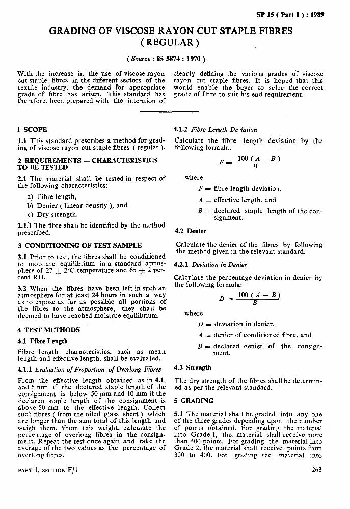
SP IS ( Part 1) : 1989
GRADING OF VISCOSE RAYON CUT STAPLE FIBRES ( REGULAR )
( Source : IS 5874 : 1970 )
With the increase in the use of viscose rayon cut staple fibres in the different sectors of the
clearly defining the various grades of viscose
textile industry, the demand for appropriate rayon cut staple fibres. It is hoped that this
grade of fibre has arisen. This standard has would enable the buyer to select the correct
therefore, been prepared with the intention of grade of iibre to suit his end requirement.
1 SCOPE
1.1 This standard prescribes a method for grad- ing of viscose rayon cut staple fibres ( regular ).
2 REQUIREMENTS - CHARACTERISTICS TO BE TESTED
2.1 The material shall be tested in respect of the following characteristics:
a) Fibre length, b) Denier ( linear density ), and c) Dry strength.
2.1;1 The fibre shall be identified by the method prescribed.
3 CONDITIONING OF TEST SAMPLE
3.1 Prior to test, the fibres shall be conditioned to moisture equilibrium in a standard atmos- phere of 27 f 2°C temperature and 65 f 2 per- cent RH.
3.2 When the fibres have been left in such an atmosphere for at least 24 hours in such a way as to expose as far as possible all portions of the fibres to the atmosphere, they shall be deemed to have reached moisture equilibrium.
4 TEST METHODS
4.1 Fibre Length
Fibre length characteristics, such as mean length and effective length, shall be evaluated.
4.1.1 Evaluation of Proportion of Overlong Fibres
From the effective length obtained as in 4.1, add 5 mm if the declared staple length of the consignment is below 50 mm and 10 mm if the declared staple length of the consignment is above 50 mm to the effective length. Collect such fibres ( from the oiled glass sheet ) which are longer than the sum total of this length and weigh them. From this weight, calculate the percentage of overlong fibres in the consign- ment. Repeat the test once again and take the average of the two values as the percentage of overlong fibres.
PART 1, SECTION F/ 1
4.1.2 Fibre Length Deviation
Calculate the fibre length deviation by the following formula:
F = lOO(A-B)
B
where
F = fibre length deviation,
A = effective length, and
B = declared staple length of the con- signment.
4.2 Denier
Calculate the denier of the fibres by following the method given in the relevant standard.
4.2.1 Deviation in Denier
Calculate the percentage deviation in denier by the following formula:
D = lOO(A-B)
B
where
D = deviation in denier,
A = denier of conditioned fibre, and
B = declared denier of the consign- ment.
4.3 Strength
The dry strength of the fibres shall be determin- ed as per the relevant standard.
5 GRADING
5.1 The material shall be graded into any one of the three grades depending upon the number of points obtained. For grading the material into Grade 1, the material shall receive more than 400 points. For grading the material into Grade 2, the material shall receive points from 300 to 400. For grading the material into
263

SP 15 ( Part 1) : 1989
Grade 3, the material shall receive points less than 300.
6 METHOD FOR AWARDING POINTS
6.1 The material shall be awarded points for the individual characteristics based on the details given in Table 1.
7 BASIS FOR ALLOCATION OF POINTS
7.1 Fibre length being the most important characteristic among all the characteristics from the point of view of spinning, it has been allotted the maximum number of points. Other characteristics have been allotted points in the order of their importance.
Table 1 Method of Awarding Points
( Clause 6.1 )
A.
B.
Characteristic (1)
When the Declared Denier is Below 2: Extra long fibre,
percent Fi;;z )length (. effec-
devlatlon, percent
Denier deviation, percent
Dry strength on single fibre tester ( g/d )
When the Declared Denier is Above 2: Extra long fibre,
percent F;;;t ygth ! efrec-
devlatlon, percent
Denier deviation, percent
Dry strength on single fibre tester (g/d 1
Points (2)
150 if 6’0 or below
150 if f6’0 and below
100 if up to and including -+lO’O
100 if above 2’3
150 if 6’0 or below
lSEe lizw~6’0 and
100 if up to and including f10
100 if above 2’0
Points
(3)
120 if between 8’0 and 6’0
l;m;f,b;tl;reen f8’0
8zOi; ;e$en f12’0 6::: bz;yp f14’0 40 if beyond &14’0
80 if betwean 2’15 60 if between 1’9 40 if below 1’9 and 2’3 (including) and 2’15 (including)
12id ‘kf obe t ween 8’0
l;z;flegyn f8’0
80 if between &12 and &lo
80 if between 1’8 and 2’0
Points
(4)
Points
(5)
9in28b;tween 12’0 60 if beyond 12
9::: b;;wF f10’0 60 if beyond MO’0
ginif k$tween 12’0 60 if beyond 12’0
9ijib$wy MO’0 60 if beyond f10.0,
6O,,‘df i;;ween f14 40 if beyond ~tl4
60,,:1 bgetween 1’6 40 if below 1’6
264 HANDBOOK OF TBXTILE TESTING*
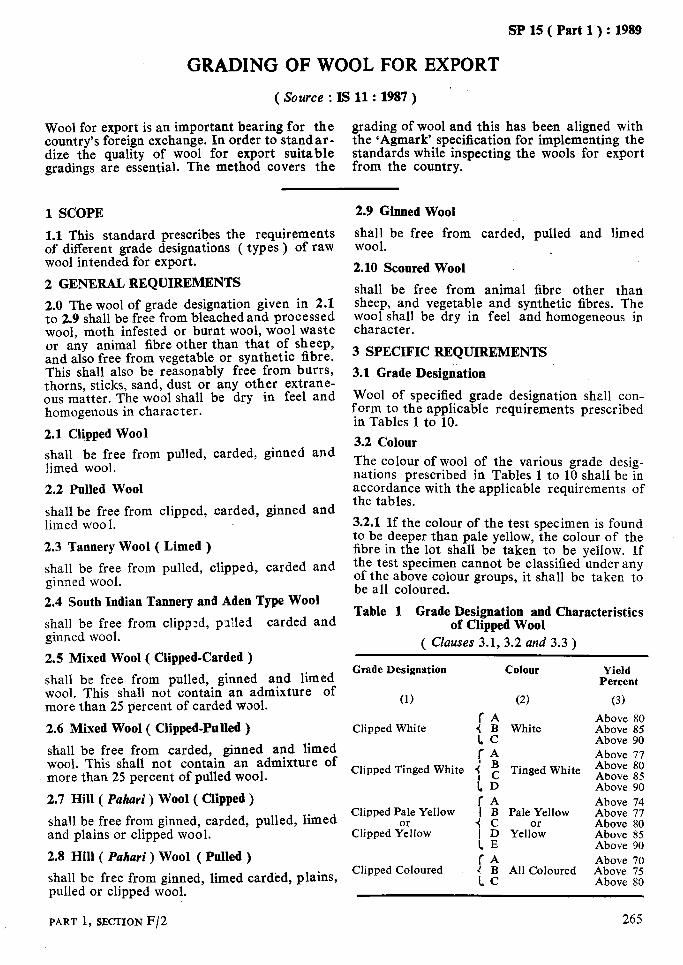
!3P 15( Part 1):1989
GRADING OF WOOL FOR EXPORT
(Source : I!3 11:1987)
Wool for export is an important bearing for the grading of wool and this has been aligned with country’s foreign exchange. In order to stand ar- the ‘Agmark’ specification for implementing the dize the quality of wool for export suitable standards while inspecting the wools for export gradings are essential. The method covers the from the country.
1 SCOPE 2.9 Ginned Wool
1.1 This standard prescribes the requirements of different grade designations ( types ) of raw wool intended for export.
2 GENERAL REQUIREMENTS
2.0 The wool of grade designation given in 2.1 to 2.9 shall be free from bleached and processed wool, moth infested or burnt wool, wool waste or any animal fibre other than that of sheep, and also free from vegetable or synthetic fibre. This shall also be reasonably free from burrs, thorns, sticks, sand, dust or any other extrane- ous matter. The wool shall be dry in feel and homogenous in character.
2.1 Clipped Wool
shall be free from carded, pulled and limed wool. *
2.10 Scoured Wool
shall be free from animal fibre other than sheep, and vegetable and synthetic fibres. The wool shall be dry in feel and homogeneous in character.
3 SPECIFIC REQUIREMENTS
3.1 Grade Designation
shall be free from pulled, carded, ginned and limed wool.
Wool of specified grade designation shall con- form to the applicable requirements prescribed in Tables 1 to 10.
3.2 Colour
2.2 Pulled Wool
shall be free from clipped, carded, ginned and limed woo 1.
The colour of wool of the various grade desig- nations prescribed in Tables 1 to 10 shall be in accordance with the applicable requirements of the tables.
2.3 Tannery Wool ( Limed )
shall be free from pulled, clipped, carded and ginned wool.
3.2.1 If the colour of the test specimen is found to be deeper than pale yellow, the colour of the fibre in the lot shall be taken to be yellow. If the test specimen cannot be classified under any of the above colour groups, it shall be taken to be all coloured.
2.4 South Indian Tannery and Aden Type Wool
shall be free from clipp:d, pzlled carded and ginned wool.
2.5 Mixed Wool ( Clipped-Carded )
shall be free from pulled, ginned and limed wool. This shall not contain an admixture of more than 25 percent of carded wool.
2.6 Mixed Wool ( Clipped-PoRed )
shall be free from carded, ginned and limed wool. This shall not contain an admixture of more than 25 percent of pulled wool.
2.7 Hill ( Puhari ) Wool ( Clipped )
shall be free from ginned, carded, pulled, limed and plains or clipped wool.
2.8 Hill ( Puhari ) Wool ( Pulled )
shall be free from ginned, limed carded, plains, pulled or clipped wool.
Table 1 Grade Designation and Characteristics of Clipped Wool
( Clauses 3.1, 3.2 and 3.3 )
Grade Designation
(1) (2)
Clipped White [ t White
:: Clipped Tinged White { g Tinged White
1D fA
Clipped Pale Yellow I B Pale Yellow
Clipped $lllow 4 c ( D Yellodw 1B IA
Clipped Coloured i BC All Coloured
Colour Yield Percent
(31
Above 80 Above 85 Above 90
2s: ;; Above 85 Above 90 Above 74 Above 77
22: :: Above 90 Above 70 Above 75 Above 80
PART 1, SECTION F/2 265
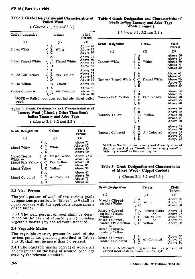
SPlS(Part1:):1969
Table 2 Grade Designatian’and’ Characteristics of Pulled Wool
( Clauses 3.1, 3.2 and 3.3 )
Grade Designation Colollr Yield Percent
(1) (2) (3) !-A
Pulled White I : White
%z :: Above 90
(A Above 77 Pulled Tinged White < g Tinged White 2::: it
iD Above 90 IA Above 74
Pulled Pale Yellow i; Pale Yellow Above 77
iD Above 80 Above 85
Pulled Yellow A Yellow Above 90 Above 70
Pulled Coloured { : All Coloured Above 75 Above 80
tzo:E - Pulled wool does not include limed pulled
Table 3 Grade Designation and Characteristics of Tannery Wool ( Limed ) Other Than South
Indian Tannery and Aden Type ( Clauses 3.1, 3.2 and 3.3 ) ~
Grade Designation Colour Yield Percent
(1) (2) (3)
f-A Above 75
Limed White i: White Above 80 Above 85
ID Above 90 Lirl;z Frnged [ i Tinged White ii4;~ Ti.5
Limed Pale Yellow 1 g Pale y&OW Above 80
Limed %llow 1 E YellowOr Above 85 Above 90
IA Above 65
Limed Coloured i g All Coloured Above 70 Above 75
iD Above 80
3.3 Yield Percent
The yield percent of wool of the various grade designations prescribed in Tables 1 to 9 shall be in accordance with the applicable requirements of the tables.
3.3.1 The yield percent of wool shall be deter- mined on the basis of scoured yield ( including vegetable matter ) by the relevant standard.
3.4 Vegetable Matter The vegetable. matter, present in wool of the various grade designations prescribed in Tables 1 to 10, shall not be more than 5-O percent.
3.4.1 The vegetable matter percent of wool shall be determined on the basis of scoured bone dry mass by the relevant standard.
Table 4 Grade Desigscltion and Characteristics of South Indian Tannery and Aden Type
Wools ( Limed )
( Cluures 3.1, 3.2 and 3.3 )
Grade Designation
(1)
Tannery White
Colour
(2)
[BA j C White
I:
Yield Percent
(3)
2t::z 2: _4bove 70 Above 75 Above 80
Tannery Tinged White 4, g Tinged White
1E
fk Tannery Pale Yellow 1 g Pale Yellow
CE f-4
Tannery Yellow !: Bc Yellow
Above 60 Above 65 Above 70 Above 75 Above 80
Above 60 Above 65 Above 70 Above 75 Above 80
Above 60 Above 65 Abave 70 Above 75 Above 80
IBA Above 55 Above 60
Tannery Coloured 4 C All Coloured Above 65
“,,“:: ;:
NOTE - South Indian tannery and Aden type wool shall be marked as ‘South Indian tannery wool’ or ‘Aden type wool’ as the case may be.
Table 5 Grade Designation and Characteristics of Mixed Wool ( Clipped-Carded)
( Clauses 3.1, 3.2 and 3.3 )
Grade Designation
(1)
Mixed ( Clipped- carded ) White
Colour
(2)
{ E White
Yield Percent
(3) Above 80 Above 85 Above 90
Mixed ( Clipped- c$hf;tirTlnged
r A Tinged White Above 74 I B or Above 77
4 C Pale Yellow Above 80 Mixed ( Clipped- I D or Above 85 carded ) Pale Yellow 1 E Yellow Above 90
Mixed &lipped- carded ) Yellow
Mixed ( Clipped- A Above 70 carded ) Coloured B All Coloured Above 75
1c Above 80
NOTE - A lot containing more than 25 percent of carded wool shall be marked as ‘Carded’.
266 HANDBOOK OF TBlffaB TBSTING

Table
SP 15 ( Part 1) : 1989
6 Grade Designation and Characteristics of Mixed Wool ( Clipped-Pulled )
Table 8 Grade Designation and Characteristics of Indian Hill ( Puhtwi ) Wool ( Pulled )
( Clauses 3.1, 3.2 and 3.3 )
Grade Designation Coloot
(1) (2)
( Clauses 3.1, 3.2 and 3.3 )
Colour Grade Designation
(1) (2)
Mixed ( Clipped- pulled ) White
Mixed ( Clipped- pulled ) Tinged White or
Mixed ( Clipped- pulled ) Pale Yellow
or Mixed (Clipped- pulled ) Yellow
White
Tinged White
Yield Percent
(3) Above 80 Above 85 Above 90 Above 74 Above 77
%: :: Above 90
Pulled Hill White
Pulled HiTTinged White
Yield Percent
(3)
White or Tinged White
Above 60 Above 65 Above 70 Above 75
Pale YZlow or
Yellow Pulled Hill Coloured All Coloured
Above 55 Above 60 Above 65 Above 70
Mixed ( Clipped- Above 70 pulled ) Coloured { $ All Coloured Above 7.5
Above 80 NOTES
Table 9 Grade Designation and Characteristics of Ginned Wool
1 Pulled wool excludes limed pulled wool. 2 A lot containing more than 25 percent of pulled
( Clauses 3.1, 3.2 and 3.3 )
wool shall be marked as ‘Pulled’. Grade Designation Colour Yield
Percent Table 7 Grade Designation and Characteristics
of Indian Hill ( Pahari ) Wool ( Clipped ) (1) (2) (3) Above 80
( Clauses 3.1, 3.2 and 3.3 ) Ginned White { i White Above 85 Above 90
Grade Designation
(1)
Colour
(2)
Yield IA Above 77
Percent Ginned Tinged White { z Tinged White AA:::: :: (3) ID Above 90
fA Above 60 Hill White or I B White or
Above 74 Above 65
Hill Tinged White i g Tmged White Above 77
Above 70 Ginned Pale Yellow j C Pale Yellow Above 80 Above 75
is Above 55 1:
Above 85 Above 90
HilllColoured , c All Coloured Above 60 rA Above 70
iD Above 65 Ginned Coloured Above 70
XL BC All Coloured Above 75 Above 80
Table 10 Grade Designation and Characteristics of Scoured Wool
( Clauses 3.1 and 3.2 )
Grade Designation Colour CorrePc;ffe;tass,
(1) (2) (3) Scoured White White Above 95 Scoured Tinged White Tinged White Above 95 Scoured Pale Yellow Pale Yellow Above 95 Scoured Yellow Yellow Above 95 Scoured Coloured All Coloured Above 95
NOTE - The corrected mass of raw wool shall be obtained by adding 17 percent of its oven dry mass.
PART 1, SECTION F/2 267

As in the Original Standard, this Page is Intentionally Left Blank
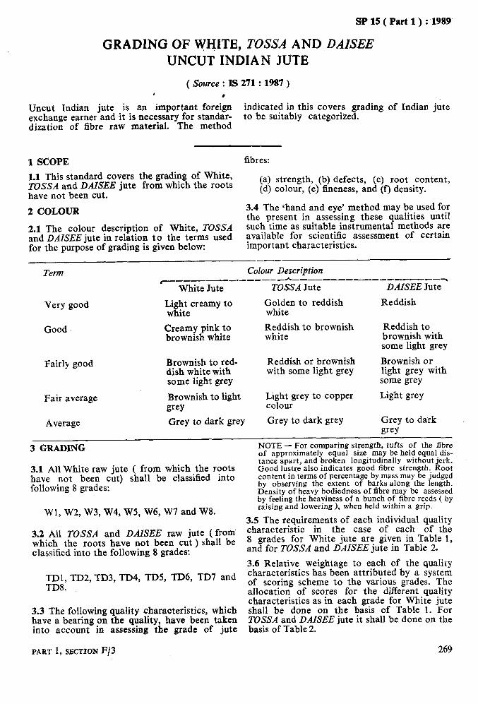
sPlS(Part1’):1989
GRADING OF WHITE, TOSSA AND DAZSEE UNCUT INDIAN JUTE
( Source : IS 271 : 1987 ) 1 .
Uncut Indian jute is an important foreign indicated in this covers grading of Indian jute exchange earner and it is necessary for standar- to be suitably categorized. dization of fibre raw material. The method
1 SCOPE fibres: ,
1.1 This standard covers the grading of White, TOSSA and DAISEE jute from which the roots have not been cut.
(a) strength, (b) defects, (c) root content, (d) colour, (e) fineness, and (f) density.
2 COLOUR 3.4 The ‘hand and eye’ method may be used for the present in assessing these qualities until
2.1 The colour description of White, TOSSA such time as suitable instrumental methods are and DAISEE jute in relation to the terms used available for scientific assessment of certain for the purpose of grading is given below: important characteristics.
Term Colour Description c--c- -________~____________________~
White Jute TOSSA Jute DAISEE Jute
Very good
Good
Light creamy to Golden to reddish white white
Creamy pink to Reddish to brownish brownish white white
Reddish
Reddish to brownish with some light grey
Fairly good
Fair average
Average
Brownish to red- dish white with some light grey
Brownish to light grey Grey to dark grey
Reddish or brownish with some light grey
Light grey to copper colour
Grey to dark grey
Brownish or light grey with some grey
Light grey
Grey to dark wy
3 GRADING
3.1 All White raw jute ( from which the roots have not been cut) shall be classified into following 8 grades:
Wl, W2, W3, W4, W5, W6, WI and W8.
3.2 All TOSSA and DAISEE raw jute ( from which the roots have not been cut ) shall be classified into the following 8 grades:
NOTE - For comparing strength, tufts of the hbre of approximately equal size may be held equal dis- tance apart, and broken longitudinally without jerk. Good lustre also indicates good fibre strength. Root content in terms of percentage by mass may be judged by observing the extent of barks along the length. Density of heavy bodiedness of fibre may be assessed by feeling the heaviness of a bunch of fibre reeds ( by raising and lowering ), when held within a grip.
3.5 The requirements of each individual quality characteristic in the case of each of the 8 grades for White jute are given in Table 1, and for TOSSA and DAISEE jute in Table 2.
3.6 Relative weightage to each of the quality
TDl, TD2, TD3, TD4, TD5, TD6, TD7 and characteristics has been attributed by a system
TD8. of scoring scheme to the various grades. The allocation of scores for the different quality characteristics as in each grade for White jute
3.3 The following quality characteristics, which shall be done on the basis of Table 1. For have a bearing on the quality, have been taken TOSSA and DAISEE jute it shall be done on the into account in assessing the grade of jute basis of Table 2.
PART 1, SECTION F/3 269
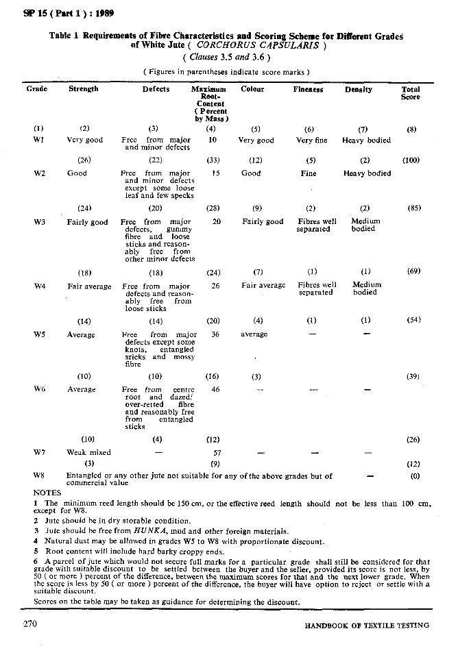
SPl5(Part1):1989
Table 1 Requirements of Fibre Characteristics and Scoring Scheme for Different Grades of White Jute ( CORCHORUS CAPSULARIS )
( Clauses 3.5 and 3.6 )
( Figures in parentheses indicate score marks )
Grade Strength
(1) Wl
w2
w3
W4
W5
W6
W7
W8
(2)
Very good
(26)
Good
(24)
Fairly good
(18)
Fair average
(14)
Average
(10)
Average
(10)
Weak mixed
(31 Entangled or any other jute not suitable for any of the above grades but of commercial value
Defects Maximum Root-
Content ( Percent by Mass 1
(3) Free from major
and minor defects
(22)
Free from major and minor defects except some loose leaf and few specks
(4) 10
(33)
15
(20)
FTe;eckom major
fibre &d gyzyJ sticks and reason- ably free from other minor defects
(18)
Free from major defects and re;asz;- ably free loose sticks
(14)
Free from major defects except some knots, entangled sricks and mossy fibre
(101
Free from centre root and dazed/ over-retted fibre and reasonably free from entangled sticks
(4) -
(28)
20
(24)
26
(20)
36
(16)
46
(12)
57
(9)
Colour
(5) Very good
(12)
Good
(9)
Fairly good
(7)
Fair average
(4)
average
(3) -
Fineness Density Total Score
(‘5) Very fine
(7) Heavy bodied
(8)
(5)
Fine
(2)
Fibres well separated
(1) Fibres well separated
(1) -
-
(2) wo)
Heavy bodied
(1)
-
(85)
(69)
(54)
(39)
(26) -
(121 - (0)
NOTES 1 The minimum reed length should be 150 cm, or the effective reed length should not be less than 100 cm, except for W8. 2 Jute should be in dry storable condition. 3 Jute should be free from HUNKA, mud and other foreign materials. 4 Natural dust may be allowed in grades W5 to W8 with proportionate discount. 5 Root content will include hard barky crappy ends. 6 A parcel of jute which would not secure full marks for a particular grade shall still be considered for that grade with suitable discount to be settled between the buyer and the seller, provided its score is not less, by 50 ( or more 1 percent of the difference, between the maximum scores for that and the next lower grade. When the score is less by 50 ( or more ) percent of the difference, the buyer will have option to reject or settle with a suitable discount. Scores on the table may be taken as guidance for determining the discount.
270 HANDBOOK OF TEXTILE TESTING
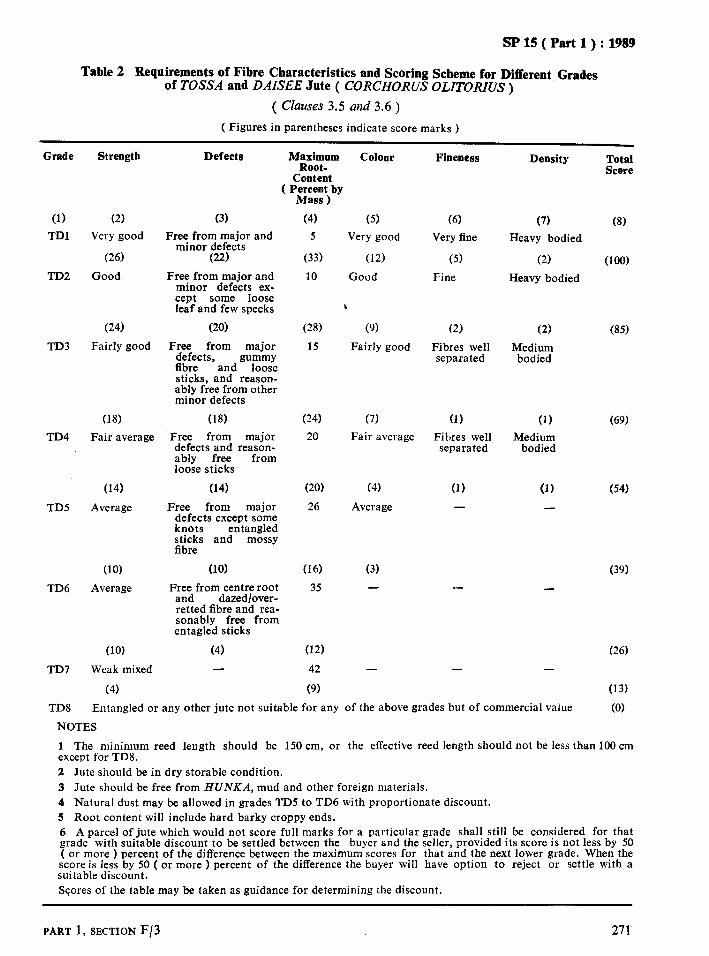
SP 15 ( Part 1) : 1989
Table 2 Requirements of Fibre Characteristics and Scoring Scheme for Different Grades of TOSSA and DAISEE hte ( CORCHORUS OLITORIUS )
( Clauses 3.5 and 3.6 )
( Figures in parentheses indicate score marks )
Grade Strength
(1)
TDl
TD2
(2)
Very good
(26)
Good
TD3
(24)
Fairly good
TD4
(18)
Fair average
TDS
(14)
Average
TD6
(10)
Average
TD7
TD8
(10)
Weak mixed
(4)
Defects Maximum Colour Root-
Content ( Percent by
(3)
Free from major and minor defects
(22)
Free from major and minor defects ex- cept some loose leaf and few specks
(20)
Free from major defects, gummy fibre and loose sticks, and reason- ably free from other minor defects
(18)
Free from major defects and reason- ably free from loose sticks
(14)
Free from major defects except some knots entangled sticks and mossy fibre
(10)
Free from centre root and dazed/over- retted fibre and rea- sonably free from entagled sticks
(4) -
Mass 1
(4)
5
(33)
10
(28)
15
(24)
20
(20)
26
(16)
35
(12)
42
(9)
(5) Very good
(12)
Good
\
(9)
Fairly good
(7)
Fair average
(4)
Average
(3) -
Fineness
(6)
Very fine
(5)
Fine
(2)
Fi bres well separated
(1)
Fibres well separated
(1) -
-
-
Density Total Score
(7)
Heavy bodied
(2)
Heavy bodied
(8)
(100)
(1) Medium
bodied
(1)
(85)
(69)
(54)
(39)
(26) -
(13)
Entangled or any other jute not suitable for any of the above grades but of commercial value (0)
NOTES
1 The minimum reed length should be 150 cm, or the effective reed length should not be less than 100 cm except for TD8. 2 Jute should be in dry storable condition. 3 Jute should be free from HUNKA, mud and other foreign materials. 4 Natural dust may be allowed in grades TD5 to TD6 with proportionate discount. 5 Root content will include hard barky crappy ends. 6 A parcel of jute which would not score full marks for a particular grade shall still be considered for that grade with suitable discount to be settled between the buyer and the seller, provided its score is not less by 50 ( or more ) percent of the difference between the maximum scores for that and the next lower grade. When the score is less by 50 ( or more ) percent of the difference the buyer will have option to reject or settle with a suitable discount. Scores of the table may be taken as guidance for determining the discount.
PART 1, SECTION F/3 271

As in the Original Standard, this Page is Intentionally Left Blank

SP 15 ( Part 1) : 1989
GRADING OF UNCUT INDIAN BIMLI
( Source : IS 11596 : 1986 )
Uncut Indian ‘Bimli is an important foreign exchange earner and it is necessary for standar-
indicated in this covers grading
dization of fibre raw material. The method ‘Bimli’ to be suitably categorized,
1 SCOPE 3 GRADING
1.1 This standard covers grading of Bimli fibres from which roots have not been cut.
1.2 The strength aspect of the fibres is classi- fied depending upon their tenacity. The terms used for the purpose of grading are ‘Good’, ‘Fair’ ‘Average’ and <Weak mixed’.
NOTES
1 Tenacity is the breaking load of a material under test divided by the linear density of the unstrained material, expressed as grams per tex.
2 Linear density is the mass per unit length, the quotient obtained by dividing the mass of the fibre or yarn by its length- When ihe mass is expressed in grams and the length in kilometres, the resulting value’, that is, the quotient, is expressed as tex.
2 COLOUR
2.1 The colour description of fibres in relation to the terms used for the purpose of grading is given below:
Good
Aver age
Creamy to whitish
Greyish to dark
of Indian
3.1 The Bimli fibre ( from which roots have not been cut ) shall be classified into 4 grades as given in Table 1. 3.2 The ‘hand and eye’ method may be used for assessing these qualities as is presently in vogue in trade but in case of ?ny dispute, the corresponding test method applicable for jute, mesta and Bimli as mentioned in the table may also be followed for correct assessment on scientific basis.
NOTE - According to the trade practice for compa- ring strength, the tufts of fibres of approximately equal size held equal distance apart, are broken longitudinally without jerk. Good listre indicates good fibre strength. Root content in terms of per- centage by mass is judged by observing the extent of foots along the length. Light or heavy bodiedness of the fibre is assessed bv feeling the lightness or heavi- ness of a bunch of fibre ree& (by raising and lower- ing ) when held within a grip.
3.3 Relative weightage to each of the quality characteristics is attributed by a system of scoring for various grades by ‘hand and eye’ method for routine grading. The marks allocat- ed are on the basis of the objective assessment of the different quality characteristics and as such shall be used for the purpose of grading on the basis as given in Table 1.
PART 1, SECTION F/4 213

SP 15 ( Part 1 ) : 1989
Table 1 Requirements of Fibre Characteristics and Scoring Scheme for Different Grades of Uncut Indian Bimli
( Clauses 3.1 and 3.3 )
(1) (2) B-l Good
B-2
( 25 I
Fair
( 18 1
B-3 Average
(IO)
B-4
Grade Strength
NOTES
Defects
(3)
Free from major defects and crappy fibre and reasonably free from leaves and specks
( 30 1
Substantially free from major defects except some knots and entan- ;Jh& sti;vakbut free
crappy ends
(24 1
Fyfd from centre roots reasonably free
from overretted fibres and runners
(15 1
All other Bimli not con- forming to any of the above grades but of commercial value. It mav contain Habi Jabi
h$;im;m Root Colour t Per-
cent bi Mass ( Weight )
(4)
10
(5)
Good
( 30 )
(18)
(6) Average
Fineness
(6) Fine, well
segregated fibre reeds
Heaviness/ Total Lightness Score
(7) (8)
Heavy
(3) (6) 100
Coarse Average
( 22 )
( 25 1
(151
bui not Feswa (101
(2) (1) - -
1 The minimum reed length should be 150 cm or the effective reed length should not except for grade B-4. The root content includes hard barky crappy ends. 2 The fibre should be in dry storable condition. 3 The fibre should be free from mud and other foreign materials. 4 Natural dust may be allowed in Grade B-2, B-3 and B-4 with proportionate discount.
(31 -
70
40
be less than 1Oe cm
5 A parcel of Bimli which would not score full marks for a particular grade shall still be considered for that grade with suitable discount to be settled between the buyer and the seller provided its score is not less by 50 ( or more > percent of the difference between the maximum scores for that and the next lower grade. When the score is less by 50 ( or more I percent of the difference, the buyer will have the option to reject or settle with a suitable discount. 6 Scores in the table may be taken as guidance for determining the discount.
274 HANDBOOK OE TEXTILE TESTING

SP 15 ( Part 1) : 1989
GRADING OF UNCUT INDIAN Mli’S”A
( Source : IS 9846 : 1981)
Uncut Indian ‘Mesta’ is an important foreign exchange earner and it is necessary for stand-
indicated in this covers grading
ardization of fibre raw material. The method ‘Mesta’ to be suitably categorized.
1 SCOPE 3 GRADING
1.1 This standard covers grading of MESTA fibres from which the roots have not been cut.
1.2 The strength aspect of the fibres is classified depending upon their tenacity. The terms used ?;6;ie purpose of grading are ‘Very good’,
9
mixed’: ‘Fairly good’, ‘Average’ and ‘Weak
NOTES
1 Tenacity is the breaking load of material under test divided by the linear density of the unstrained material, expressed as grams per tex. 2 Linear density is the mass per unit length; the quotient obtained by dividing the mass of fibre or yarn by its length. When the mass is expressed in grams and the length in kilometres, the resulting value, that is, quotient, is expressed as tex.
2 COLOUR
2.1 The colour description of fibres in relation to the terms used for the purpose of grading is given below:
Good Creamy to whitish
Fair average Light grey
Average Greyish to dark
of Indian
3.1 The MESTA fibre ( from which roots have not been cut ) shall be classified into 6 grades as given in Table 1.
3.2 The ‘hand and eye’ method may be used in assessing these qualities as is presently in vogue in the trade but in the case of dispute, the corresponding test method applicable for jute as mentioned in the table may also be followed for correct assessment on scientific basis.
NOTE - According to the trade practice for compar- ing strength, the tufts of fibres of aouroximatelv equal size held equal distance apart,- ire broken longitudinally without jerk. Good lustre indicates good fibre strength. Root content in terms of percen- tage by mass is judged by observing the extent OF roots along the length. Light or heavy bodiedness of the fibre is assessed by feeling the lightness or heavi- ness of a bunch of fibre reeds ( by raising and lower- ing ) when held within a grip.
3.3 Relative weightage to each of the quality characteristics is attributed by a system of scoring for various grades by the ‘hand and eye’ method for routine grading. The marks alloca- ted are on the basis of the objective assessment of the different quality characteristics and as such shall be used for the purpose of grading on the basis as given in Table 1.
PART 1, SECTION F/5 275

SP 15 ( Part 1) : 1989
Table 1 Requirements of Fibre Characteristics and Scoring Scheme for Different Grades of Uncut Indian MESTA ( Clauses 3.1 and 3.3 )
Grade Strength Defects
(1) (2) MESTA 1 Very Good
(25) MESTA 2 Good
(3)
Fr,e,efrc;; major and minor except brown
leaves and appreciably free from specks
(25) Free from major defects and
loose sticks; substantially free from knots and gummy and crappy fibres
(21)
MESI’A 3 Fairly Good
(17)
MESTA 4 Average
(21)
Free from major defects except knots
(17)
Free from centre roots, dazed and over-retted- fibres and reasonably free z;cTsrunners and entangled
(13)
Reasonably free from runners
(13)
MESTA 5 Weak mixed
(5)
Ma&m;m Colour
Content, Percent
by Mass ( Weight 1
Fineness
(5)
(4)
12
(27)
20
(22)
30
(17)
40
(14)
50
(10)
(5) (6)
Good Finer with fibre reeds well segre- gated
(15) (5)
Fair Fine, with average fibre well
segregated
(11) (3)
Average Coarse
(7) (1)
Heaviness Total
LigZiess Score
(7) (8) Very heavy, with thinner reeds
(3)
Heavy, with broader thicker reeds
loo
(2)
Medium bodied
(1)
80
60
40
20
MESTA 6 All MESTA not conforming to any of the above grades but of commercial value.
NOTES
1 The minimum reed length should be 150 cm, or the effective reed length should be not less than 100 cm except for MESTA 6. 2 The fibre should be in dry storable condition. 3 The fibre should be free from HUNKA, mud and other foreign materials. 4 Natural dust may be allowed in grades MESTA 4, MESTA 5 and MESTA 6 with proportionate discount. 5 Root content will include hard barky crappy ends. 6 A parcel of MESTA which would not score full marks for a particular grade shall still be considered for that grade with suitable discount to be settled between the buyer and the seller, provided its score is not less by 50 ( or more 1 percent of the difference between the maximum scores for that and the next lower grade. When the score is less by 50 ( or more ) percent of the difference the buyer will have option to reject or settle with a suitable discount. 7 Scores in the table may be taken as guidance for determining the discount.
276 HANDBOOK OF TEXTILE TESTING

SP 15 ( Part 1) : 1989
FINENESS GRADES OF WOOL
( Source : Is 5910 : 1977 )
The fineness grades of wool fibre has an impor- tant bearing in the classification of grades. The
to assess the wool fibre, for various grades.
method covers grading of fineness of wool fibre, Assessment of the fineness grades is on the basis of average micron value and standard deviation
both for imported and indigenous wool, in order of fibre fineness.
1 SCOPE
1.1 This standard covers the classification of fitieness grades of the fibres in raw wool.
1.2 This is also applicable to $001 yarns and fabrics processed on the woollen system. How- ever, the test results obtainedon the wool fibres removed from yarns and fabrics may not meet the specifications as given in the standard which are for raw wool. If these meet the speci- fications of the next coarser grade, the same shall be considered as satisfying requirements.
2 GRADES
2.1 The specifications for various grades of imported and indigenous wool are given in Table 1.
3 METHOD OF TEST
3.1 Determine the diameter of wool fibres by the relevant method. The number of observa- tions to be made for this purpose shall be such as to obtain confidence limits of the mean with- in &l-O pm at a probability level of 95 per- cent.
3.1.1 The number of fibres to be observed in order to attain the above stated confidence limits of the mean shall be determined by the following formula, which, however, shall not exceed 1 000:
to s n=
( > -z- where
n = number of fibres; t = probability factor ( 1.96 for 95 per-
cent probability level ); 0 = standard deviation of fibre dia-
meter; and E = desired precision of the mean, that
is, f 1-O pm.
NOTE - An example illustrating the calculation of the total number of observations, is given below:
On observing the diameter of 200 fibres, the standard deviation is found to be 14’25 microns. The number (n) of fibres to be tested shall be:
PART 1, SECTION F/6
3.2 Calculate the average fibre diameter and standard deviation.
4 ASSIGNMENT OF GRADE
4.1 Compare the average fibre diameter and standard deviation in fibre diameter as deter- mined in 3.2, with the specifications for various grades given in Table 1. Assign to the wool the grade that corresponds to the observed average fibre diameter and standard deviation. If the measured average fibre diameter and standard deviation correspond to a single grade, assign that grade to the wool. If the standard devia- tion exceeds the maximum specified for the grade to which the observed average fibre diameter corresponds, assign to the wool the next coarser grade.
4.1.1 A few examples illustrating the assignment of grade are given below:
Imported Wool
Example 1:
Average fibre diameter 24.24 pm Standard deviation’ 6.21 pm Assigned grade 60s
Example 2:
Average fibre diameter 31.23 pm Standard deviation 8-72 Pm Assigned grade 48s
Example 3:
Average fibre diameter 31.23 pm Standard deviation 9.30 pm Assigned grade 46s
Indigenous Wool
Example 4:
Average fibre diameter 34.15 pm Standard deviation 13.12 pm Assigned grade 48s
277

SP 15 ( Part 1) : 1989
Example 5:
Average fibre diameter Standard deviation Assigned grade
34.15 pm 14.23 pm 44s
Example 6:
Average fibre diameter Standard deviation Assigned grade
37.23 pm 15.91 pm 40s
Table 1 Specifications for Grades of Wool
( Clauses 2.1 and 4.1 )
Grade Imported Wool ~-------2.--__--___~ Range for Average
Fibre Diameter
. (1) (2)
Standard Dev$Fxn,
(3)
wn
3’59
4’09
4’59
5.19
5’89
6’49
7’09
7’59
8’19,
8’69
9’09
9’59
10’09
10’69
11’19
Finer than 80s
80s
10s
64s
62s
60s
58s
56s
54s
50s
4%
46s
44s
40s
36s
Coarser than 36s
Under 17’70
17’70 to 19’14
19’15 ,, 20’59
20’60 ,, 2.2’04
22’05 ,, 23’49
23’50 ,, 24’94
24’95 ,, 26’39
26’40 ,, 27’84
27’85 ,, 29’29
29’30 ,, 30’99
31’00 ,, 32’69
32’70 ,) 34’39
34.40 ,, 36’19
36’20 ,, 38’09
38’10 ,, 40’20
Over 40’20 -
Indigenous Wool ~_---__-h--_____~
Range for Average Fibre Diameter
Standard Deviation,
Max
(5)
Pm
-
-
(4)
iLm
-
-
-
-
-
-
-
-
-
-
Under 34’40
-
34’41 to 36’20
36’21 ,, 38’60
38’61 ,, 40’80
Over 40’81
-
-
-
-
-
-
-
-
13’50
-
14’75
16’25
15’00
-
HANDBOOK OF TEXTILE TE.STING
-
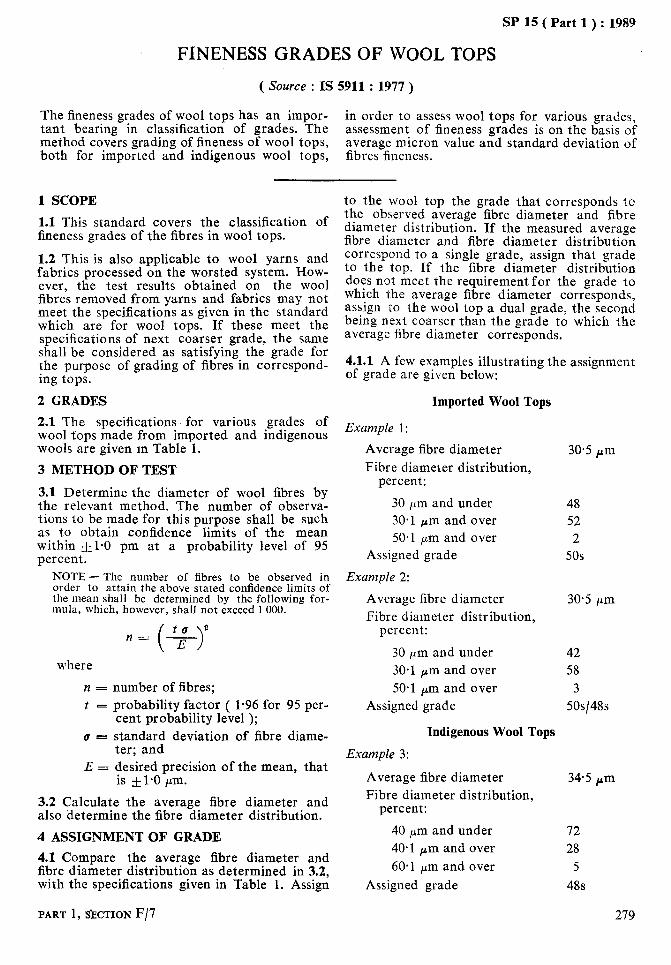
SP 15 ( Part 1 ) : 1989
FINENESS GRADES OF WOOL TOPS
( Source : IS 5911 : 1977 )
The fineness grades of wool tops has an impor- tant bearing in classification of grades. The
in order to assess wool tops for various grades,
method covers grading of fineness of wool tops, assessment of fineness grades is on the basis of average micron value and standard deviation of
both for imported and indigenous wool tops, fibres fineness.
1 SCOPE
1.1 This standard covers the classification of fineness grades of the fibres in wool tops.
1.2 This is also applicable to wool yarns and fabrics processed on the worsted system. How- ever, the test results obtained on the wool fibres removed from yarns and fabrics may not meet the specifications as given in the standard which are for wool tops. If these meet the specifications of next coarser grade, the same shall be considered as satisfying the grade for the purpose of grading of fibres in correspond- ing tops.
2 GRADES
2.1 The specifications for various grades of wool fops made from imported and indigenous wools are given m Table 1.
3 METHOD OF TEST
3.1 Determine the diameter of wool fibres by the relevant method. The number of observa- tions to be made for this purpose shall be such as to obtain confidence limits of the mean within -+1-O pm at a probability level of 95 percent.
NOTE - The number of fibres to be observed in order to attain the above stated confidence limits of the mean shall be determined by the following for- mula, which, however, shall not exceed 1000.
to 2 n= - ( ) E
where
n = number of fibres; t = probability factor ( l-96 for 95 per-
cent probability level ); u = standard deviation of fibre diame-
ter; and E = desired precision of the mean, that
is fl-0 pm.
3.2 Calculate the average fibre diameter and also determine the fibre diameter distribution.
4 ASSIGNMENT OF GRADE
4.1 Compare the average fibre diameter and fibre diameter distribution as determined in 3.2, with the specifications given in Table 1. Assign
to the wool top the grade that corresponds to the observed average fibre diameter and fibre diameter distribution. If the measured average fibre diameter and fibre diameter distribution correspond to a single grade, assign that grade to the top. If the fibre diameter distribution does not meet the requirement for the grade to which the average fibre diameter corresponds, assign to the wool top a dual grade, the second being next coarser than the grade to which the average fibre diameter corresponds.
4.1.1 A few examples illustrating the assignment of grade are given below:
Imported Wool Tops
Example 1:
Average fibre diameter 30.5 Pm Fibre diameter distribution,
percent:
30 E&m and under 48 30.1 pm and over 52 50.1 pm and over 2
Assigned grade 50s
Example 2:
Average fibre diameter 30.5 pm Fibre diameter distribution,
percent:
30 pm and under 42 30.1 pm and over 58 50.1 Pm and over 3
Assigned grade 5Os/48s
Indigenous Wool Tops
Example 3:
Average fibre diameter 34.5 Pm Fibre diameter distribution,
percent:
40 pm and under 72 40.1 Pm and over 28 60.1 Pm and over 5
Assigned grade 48s
PART ~,SECTION F/7 279
SP 15 ( Part 1) : 1989
Example 4:
Average fibre diameter Fibre diameter distribution,
percent:
40 pm and under 40-l pm and over 60-l pm and over
Assigned grade
34.5 pm
63 37
6 48~144s
Example 5:
Average fibre diameter Fibre diameter distribution,
percent:
40 and under pm 40-l and over pm 60.1 and over pm
Assigned grade
39.5 C”m
54 46 7
40s
iS0 HANDBOOK OF TEXTILE TESTING
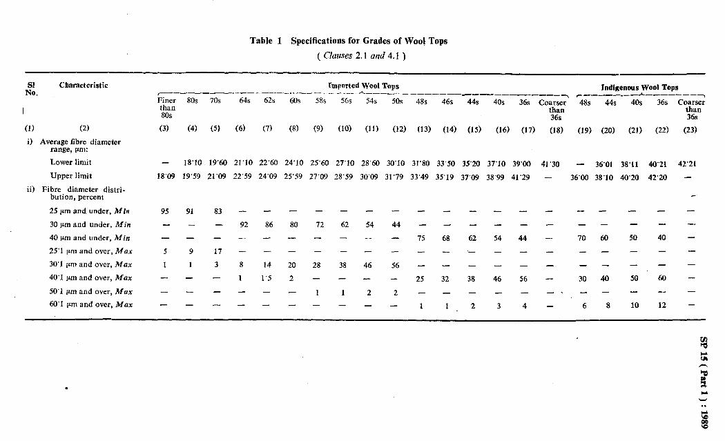
Table 1 Specifications for Grades of Woo! Tops
( Clauses 2.1 and 4.1 )
Sl No.
Characteristic
I
(1) (2)
i) Average fibre diameter range, pm:
Lower limit
Upper limit
ii) Fibre diameter distri- bution, percent
25 pm and under, Min
30 pm and under, Min
40 pm and under, Min
25’1 pm and over, Max
30’1 pm and over, Max
40’1 pm and over, Max
50’1 pm and over, Max
60’1 pm and over, Max
Imported Wool Tops _--_-___----_---------~----~ Indigeneus Wool Tops
----- ______ --_--_-_____ . __-_____-*_-_--------\ Finer than 80s
(3)
80s 70s 64s 62s
(4) (5) (6) (7)
60s
(8)
58s
(9)
56s 54s 50s 48s 46s 44s 40s 36s Co;gnr ’ .48s 44s 40s 36s Cysz’
36s 36s
(10) (11) (12) (13) (14) (15) (16) (17) (18) (19) (20) (21) (22) (23)
-
18’09
18’10 19’60 21’10 22’60
19’59 21’09 22’59
95
-
-
5
1 -
-
-
91 83
- -
- -
9 17
1 3
- -
-- -
- -
-
92
-
-
8
1
-
24’09
86
-
14
1’5
-
-
24’10 25’60 27’10 28’60 30’10 31’80 33’50 35’20 37’10 39’00 41’30 - 36’01 38’11 40’21 42’21
25’59 27’09 28’59 30’09 31’79 33’49 35’19 37’09 38’99 41’29 - 36’00 38’10 40’20 42’20 -
-
80 -
-
20
2
-
-
72 -
-
28
-
1 -
-
62 -
-
38
-
1 -
- -
54 44 - -
- -
46 56
- -
2 2 - -
- - - - - - - -
- - - - - - - - -.
75 62 54 44 - 70 60 50 40 - ‘- - - - - - - - -
-
25
-
1
68
-
-
32
- -- - - - - -
38 46 56 - 30 40 JO 60 - - - _ - -- - - - -
1 2 3 4 - 6 8 10 12 -
.

As in the Original Standard, this Page is Intentionally Left Blank
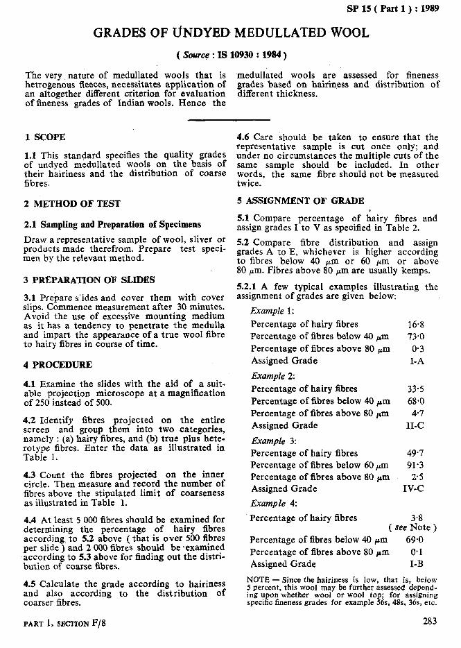
SP 15 ( Part 1) : 1989
GRADES OF UNDYED MEDULLATED WOOL
The very nature of medullated wools that is medullated wools are assessed for fineness hetrogenous fleeces, necessitates application of grades based on hairiness and distribution of an altogether different criterion for evaluation different thickness. of fineness grades of Indian wools. Hence the
1 SCOPE
1.1 This standard specifies the aualitv grades of undyed medullated wools on’ the -b&is of their hairiness and the distribution of coarse fibres.
2 METHOD OF TEST
2.1 Sampling and Preparation of Specimens
Draw a representative sample of wool, sliver or products made therefrom. Prepare test speci- men by the relevant method.
3 PREPARATION OF SLIDES
3.1 Prepare sides and cover them with cover slips. Commence measurement after 30 minutes. Avoid the use of excessive mounting medium as it has a tendency to penetrate the medulla and impart the appearance of a true wool fibre to hairy fibres in course of time.
4 PROCEDURE
4.1 Examine the slides with the aid of a suit- able projection microscope at a magnification of 250 instead of 500.
4.2 Identify fibres projected on the entire screen and group them into two categories, namely : (a) hairy fibres, and (b) true plus hete- rotype fibres. Enter the data as illustrated in Table 1.
4.3 Count the fibres projected on the inner circle. Then measure and record the number of fibres above the stipulated limit of coarseness as illustrated in Table 1.
4.4 At least 5 000 fibres should be examined for determining the percentage of hairy fibres according to 5.2 above ( that is over 500 fibres per slide ) and 2 000 fibres should be *examined according to 5.3 above for finding out the distri- bution of coarse fibres.
4.5 Calculate the grade according to hairiness and also according to the distribution of coarser fibres.
4.6 Care should be taken to ensure that the representative sample is cut once only; and under no circumstances the multiple cuts of the same sample should be included. In other words, the same fibre should not be measured twice.
5 ASSIGNMENT OF GRADE
5.1 Compare percentage of hairy fibres and assign grades I to V as specified in Table 2.
5.2 Compare fibre distribution and assign grades A to E, whichever is higher according to fibres below 40 pm or 60 pm or above 80 pm. Fibres above 80 I*m are usually kemps.
5.2.1 A few typical examples illustrating the assignment of grades are given below:
Example 1:
Percentage of hairy fibres Percentage of fibres below 40 pm Percentage of fibres above 80 fLm Assigned Grade
Example 2:
16.8 73.0 O-3 I-A
Percentage of hairy fibres Percentage of fibres below 40 pm Percentage of fibres above 80 pm Assigned Grade
Example 3:
33.5 68.0 4.7
II-C
Percentage of hairy fibres 49.7 Percentage of fibres below 60 rm 91.3 Percentage of fibres above 80 pm 25 Assigned Grade IV-C
Example 4:
Percentage of hairy fibres 3.8 ( see Note )
Percentage of fibres below 40 pm 69.0 Percentage of fibres above 80 pm 0.1 Assigned Grade I-B
NOTE - Since the hairiness is low, that is, below 5 percent, this wool may be further assessed depend- ing upon whether wool or wool top; for assigning specific fineness grades for example 56s, 48s, 36s, etc.
PART 1, SECTION F/8 283
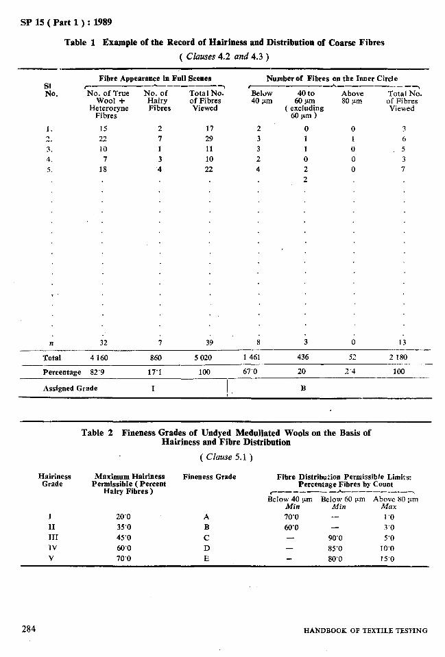
SP 15 ( Part 1) : 1989
Table 1 Example of the Record of Hairiness and Distribution of Coarse Fibres
( Clauses 4.2 and 4.3 )
SI No.
1.
2.
3. 4.
5.
Fibre Appearance in Full Scenes r_-_-.__A---_---_~ No. of True No. of Total No.
Wool + Hairy of Fibres H;ybTe;yne Fibres Viewed
15 2 17 22 7 29 10 1 11
7 3 10 18 4 22
n j2 ; 39
Number of Fibres on the Inner Circle #mm---- -----_h,_--_-_--__~
BelOW 40 to Above Total No. 40 pm 6Orm 80 pm of Fibres
( excluding Viewed 60pm)
2 0 0 3 3 1 1 6 3 1 0 5 2 0 0 3 4 2 0 7
2
s j d 13
Total 4 160 860 5 020 1 461 436 52 2 180
Percentage 82’9 17’1 100 67’0 20 2’4 100
Assigned Grade I B
Table 2 Fineness Grades of Undyed Medullated Wools on the Basis of Hairiness and Fibre Distribution
( Clause 5.1 )
Hairiness Grade
I II
III IV V
Maximum Hairiness Fineness Grade Fibre Distribution Permissible Limits: Permissible ( Percent
Hairy Fibres ) Percentage Fibres by Count
c-------- L-___-___-~ BelowM$ pm Below 60 pm Abzaex80 pm
Min 20’0 A 70’0 - 1‘0 35’0 B 60’0 - 3’0
45’0 C 90’0 5’0 60’0 D - 85’0 10’0 70’0 E 80’0 15’0
284 HANDBOOK OF TEXTILB TES’FING
-
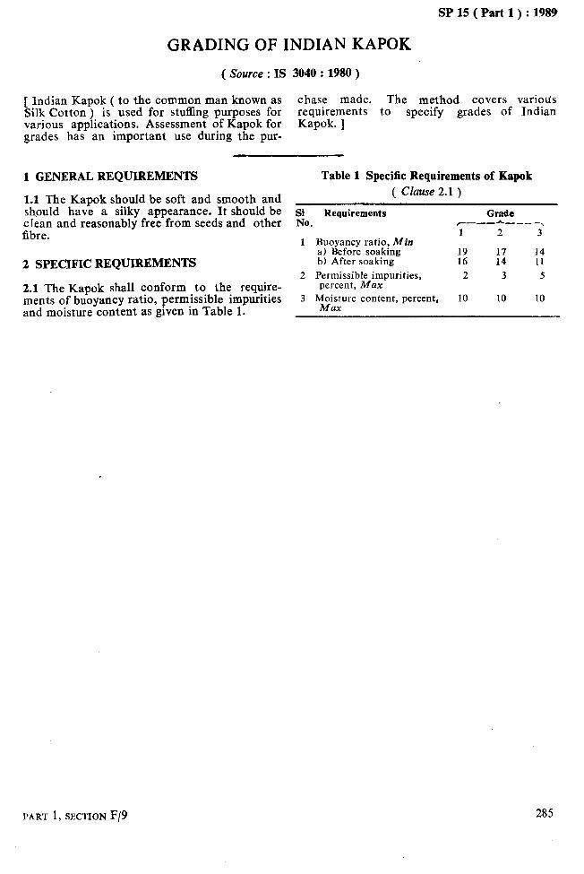
SP 15 ( Part 1) : 1989
GRADING OF INDIAN KAPOK
( Source : IS 3040 : 1980 )
[ Indian Kapok ( to the common man known as chase made. The method covers variods Silk Cotton ) is used for stuffing purposes for requirements to specify grades of Indian various applications. Assessment of Kapok for Kapok. ] grades has an important use during the pur-
1 GENERAL REQUIREMENTS Table 1 Specific Requirements of Kapok
1.1 The Kapok should be soft and smooth and should have a silky appearance. It should be clean and reasonably free from seeds and other fibre.
2 SPECIFIC REQUIREMENTS
2.1 The Kapok shall conform to the require- ments of buoyancy ratio, permissible impurities and moisture content as given in Table 1.
( Clause 2.1 )
Sl Requirements Grade No. C---h--_~
1 2 3 1 Buoyancy ratio, Min
a) Before soaking 14 b) After soaking :z :I 11
2 Permissible impurities, 2 3 5 percent, Max
3 M$;zre content, percent, 10 10 10
PART 1, SECTION F/9 285
--

As in the Original Standard, this Page is Intentionally Left Blank
I
SP 15 ( Part 1 ) : 1989
SECTION G
INDEX TO INDIAN STANDARDS COVERED IN THIS HANDBOOK

As in the Original Standard, this Page is Intentionally Left Blank

IS No.
2 : 1960 11 : 1987 199 : 1988
23316;;ts 1 & 2 ) :
234 : 1973
235 : 1989
236 : 1968
271 : 1987 667 : 1981 684 : 1962 744 : 1977
1348 : 1971 1349 : 1964 1377 :, 1971
SIP 15 ( Part 1 ) : 1989
LIST OF INDIAN STANDARDS REFERRED
Title
Rules for rounding off numerical values ( revised )
Grading of wool for export (second revision )
Methods for estimation of moisture, total size or finish, ash and fatty matter in grey and finished cotton textile materials ( third revision)
Methods for determination of length parameters of cotton fibres .( first revision )
Methods for determination of linear density of textile fibres ( gravi- metric method ) (first revision )
Methods for determination of tensile characteristics of individual textile fibres ($rst revision )
Methods for determination of cottonfibre maturity ( by sodium hydroxide swelling method ) (first revision )
Grading of White, TOSSA and DAIS&X uncut Indian jute ( third revision )
Methods for identification of textile fibres (first revision )
Method for determination of nep count in cotton Method for determination of wool fibre diameter - Projection micro-
scope method ( second rev ision ) Method for determination of kemp content of rawwool ( jirst revision )
Methods for determination of wool fibre content of raw wool ( revised )
Methods for determination of mean fibre length of wool (first revision )
1560 I Parts 1 8z 2 ‘I : Method for estimation of carboxvlic acid zrouns in cellulosic textile 1974
I
1564 : 1988
1611 : 1960 1793 : 1973 1889 ( Parts 1 & 2 )
1976 1889 (Parts 3 & 4)
1979 2005 : 1988
2006 : 1988
2176 : 1988
2177 : 1988
2727 : 1964
2899 : 1965 2964 : 1964
3040 : 1980 3416 : 1988
3421 : 1988
PAkT 1, SECTION G/l
s ” *
materials ( jirst revision ) Methods for quantitative chemical analysis of binary mixtures of cellulose
triacetate and certain other fibres (first revision ) Method for cotton fibre immaturity count-polarized light method Guide for marking textile materials made of wool (first revision )
Method for quantitative chemical analysis of binary mixtures of regener- ated cellulose fibres and cotton (first revision )
Method for quantitative chemical analysis of binary mixtures of regener- ated cellulose fibres and cotton (first revision )
Method for quantitative chemical analysis of binary mixtures of polya- mide fibres and certain other fibres (first revision )
Method fqr quantitative chemical analysis of binary mixtures of protein fibre with certain other non-protein fibres ( second revision )
Method for quantitative chemical analysis of binary mixtures of secondary cellulose acetate and certain other fibres (first revision )
Method for quantitative chemical analysis of mixtures of cellulose triacet- ate and secondary cellulose acetate fibres (first revision )
Method for quantitative chemical analysis of binary mixture of manila and sisal fibres
Method for determination of percentage of medullated fibres in wool Methods for detection and estimation of damage in cotton fibres due to
micro-organisms Grading of Indian Kapok (Jirst revision )
Method for quantitative chemical analysis of mixtures of polyester fibres with cotton or regenerated cellulose ( second revision )
Method for quantitative chemical analysis of binary mixtures of acrylic and certain other fibres (first revision )
289

SPlS(Part1):1989
IS No. 3429 : 1966 3430 : 1966 3674 : 1966 3675 : 1966 4203 : 1967 4807 : 1968 4871 : 1968
4902 ; 1981
5874 : 1970 5910 : 1977 5911 : 1977 6124 : 1971 6359 : 1971 6503 : 1988
6504 : 1979
6570 : 1972
6637 : 1972 6653 : 1972 6919 : 1973 7032(&arts 1 to 8 )
8387 : 1977
8476 : 1977 9022 : 1979
9068 : 1979
9308 ( Part 1 ) : 1987 9846 : 1981 9889 : 1988
9896 : 1981
10014 ( Part 1 ) : 1984
10014 ( Part 2 ) : 1981
10930 : 1984 11596 : 1986 11870: 1986
12135 : 1987
SP 11 : 1973 Recommended SI units for textiles
Title
Method for determination of solubility of wool in alkali Method for determination of solubility of wool in urea-bisulphite solution Method for determination of micronaire value of cotton fibres Method for determination of bundle strength ( tenacity ) of cotton fibres Method for determination of sulphate content in textile materials Methods of testing viscose rayon staple fibres Method for determination of lint and trash content of cotton by means of
mechanical pneumatic machines Method for determination of correct invoice weight of all wool materials
( Jirst revision )
Grading of viscose rayon cutstaple fibres ( regular ) Fineness grades of wool (Jirst revision )
Fineness grades of wool tops ($rst revision >
Method for determination of crimps in wool Methods for conditioning of textiles Method for quantitative chemical analysis of ternary mixtures of protein
fibres, nylon 6 or nylon 6.6, and certain other fibres (Jirst revision )
Method for quantitative chemical analysis of ternary mixtures of viscose rayon, cotton and protein fibres (first revision )
Method for quantitative chemical analysis. of binary mixtures of jute and animal fibres
Methods for determination of moisture in wool Methods for determination of staple length of greasy wool Methods for determination of wool fibre diameter by airflow method Physical methods of test for uncut Indian jute MESTA and BIMLI (first
revision )
Method of test for wool fibre length ( barbe and hauteur ) using a comb sorter
Method for determination of wool content in woollen textile-materials Methods for preparation of laboratory test samples and test specimens of
textile materials for chemical testing Recommended methods for the removal of non-fibrous matter prior to
quantitative analysis of fibre mixtures Birstle coir fibre (first revision )
Grading of uncut Indian MESTA Method for quantitative chemical analysis of binary mixtures of silk
and wool or hair ( jirst revision )
Method ‘for quantitative chemical analysis of mixtures of polyolefin fibres and other fibres
Methods of test for man-made staple fibres: Part 1 Determination of length
Methods of test for man-made staple fibres: Part 2 Determination of linear density
Quality grades of undyed medullated wool Grading of uncut Indian BIMLI Method for quantitative chemical analysis of binary mixtures of polypro-
pylene and polyethlene .
Method for determination of acetic acid coutent of acetate or triacetate fibre materials
290 HANDBOOK OF TEXTILE TBSTING