sp : ri hand-book - civil samuraiz | the professional …6 (4)-1969 high tensile friction grip bolts...
TRANSCRIPT

SP : 6 (4) 1969 ( Hcaflirnd 1995 )
RI HAND-BOOK FOR
STRUCTURAL E-NGINEERS
4. USE OF HIGH STRENGTH FRICTION GRIP BOLTS
BUREAU OF INDIAN STANDARDS

ISI STRUCTURAL ENGINEERS’ HANDBOOK
No. 4
.

As in the Original Standard, this Page is Intentionally Left Blank

ISI HANDBOOK
FOR
STRUCTU~RAL ENGI~NEERS
4. USE OF HIGH STRENGTH FRICTION GRIP BOLTS
BUREAU OF INDIAN STANDARDS MANAK BHAVAN, 9 BAHADUR SHAH ZAFAR MARG
NEW DELHI 110002
Gr. 11 Novembek pi> 0

BUREAU OF INDIAN STANDARDS
0 BUREAU OF INDIAN STANDARDS, 1970
Edlilon : 1st 1969
Sixth Reprint MAY 1999
UDC 621.882.2 : 624 014.2:693.81 SP : 6 (4) - 1969
Published by Bureau of Indian Standards New Delhi 110002, India

SP:6 (4)-1969
CONTENTS
FOREWORD .........
1. INTR~D~OTI~N .........
1.1 History ............
1.2 General Principles .........
1.3 Advantages of High Strength Bolts ...
1.4 Code of Practice ... ......
2. DESIGN OF JOINTS ...... ...
2.1 General ......... ...
2.2 Shear Connections .........
2.3 External Tension ...... ...
2.4 Combined Tension and Shear ... ...
2.5 Aloment Connections ... ...
2.6 Repeated \‘nriatiorl of Forces ......
3. FABRI( :ATION ......... ...
3.1 General ............
3.2 Torque Control hlethod _ ......
3.3 Part ‘1‘11~ hIethod .........
3.4 Recent Developments in High Strength Bolts
3.5 Asseml~ly ofJoints .........
3.6 Preparation of Surfaces ......
3.7 Procedure for Tightening ......
3.8 Inspection .........
3.9 Sampling .........
. . .
. . .
. .
. . .
. . .
. . .
. . .
. . .
. . .
. . .
. .
,..
. . .
. . .
. . .
. . .
. . .
. . .
. . .
. . .
. . .
. . .
. . .
r\pp~ymx A COMWM,I-ION OF STRUCTURAL ENGINEERING SECTIONAL CC)MM~TTEE [ SMBDC 7 ), AND OF PANEL FOR CODE OF PRACTICE FOR USE OF HIGH TENSJLE FRICTION GRIP FAWENERS (SMBDC 7/P 12) . . . I.. . . . . . . . . .
A~I_‘E.UDIX B TNDIAN STANDARDS AND OTHER PUBLICATIONS OF ISI REI.ATING TO STRUCTURAL ENGINEERING . . . . .
.A~~EN~DIX C USE OF DIGITAL COMPUTERS FOR DESIGN OF JOINTS
5
PAGE
7
9
9
9
10
15
15
15
15
24
28
35
35
36
36
37
43
44
45
49
50
50
51
52
54
56
.

As in the Original Standard, this Page is Intentionally Left Blank

SP:6 (4)-1969
FOREWORD
This handbook, which has been processed by the Structural Engineer- ing Sectional Committee, SMBDC 7, the composition of which is given in Appendix A, had been approved for publication by the Structural and Metals Division Council and the Civil Engineering Division Council of ISI.
Steel, which is a very important basic raw material for industrializ- ation, had been receiving attention from the Planning Commission, even from the very early stages of the country’s First Five Year Plan period. The Planning Commission not only envisaged an increase in production capacity in the country, but also considered the question of even greater importance, namely, the taking of urgent measures for the conservation of available resources. Its expert committees came to the conclusion that a good proportion of the steel consumed by the structural steel industry in India could be saved if higher efficiency procedures were adopted in the production and use of steel. The Planning Commission, therefore, recommended to the Government of India that the Indian Standards Institution should take up a Steel Economy Project and prepare a series of Indian Standard specifications and codes of practice in the field of steel production and utilization.
Over sixteen years of continuous study in India and abroad, and the deliberations at numerous sittings of committees, panels and study groups, have resulted in the formulation of a number of Indian Standards in the field of steel production, design and use, a list of which is given in Appendix B.
In order to guide the engineers in the use of various Indian Standard codes of practice, IS1 undertook preparation of a number of handbooks, This handbook, which is the fourth in the series, relates to the use of high tensile friction grip bolts. The first one on structural steel sections was published in 1959. The second and third covering beams and columns respectively were published in 1962.
This handbook 1s intended to present the important principles and as- sumptions involved in the use of high tensile friction grip bolts in structural fabrication and other engineering purposes and to provide illustrative examples to guide the designers in the analysis of practical design problems.
T

SP:6 (4)-1969
High tensile friction grip bolts are comparatively a recent develop- ment. Though the information on high tensile friction grip bolts published in the scientific and technical journals is voluminous, there was not,.a single publication giving all the information about their use. Necessity was, therefore, felt for a handbook to serve as a guide for design engineers.
The subject is introduced by considering the various limits and use- fulness of high tensile friction grip bolts. Their advantages over the ordinary bolts have been explained.
The design of joints carrying different types of forces has been dealt with in 2. The advantages of high tensile friction grip bolts in resisting dynamic forces and fluctuating stresses are described. D,esign examples have been included to make the different concepts clear.
Different methods of fabrication using high tensile friction grip bolts have been described in 3. The inspection requirements of joints and colrnections have also been dealt with. Appendix C describes the typical flow diagram for computer programme to solve problems connected with high tensile friction grip bolts.
This handbook is based on and requires reference to the following publications issued by ISI:
IS : 3757-1967 Specification for high tensile friction grip fasteners for structural engineering purposes
IS : 4000- 1967 Code of practice for assembly of structural .joints using high tensile friction grip fasteners
In the preparation of this handbook, the technical committee has derived valuable assistance from Prof P.V. Pawar, M.Sc (Engg j, London, DIC of College of Military Engineering, Poona. Prof Pawar prepared the preliminary draft of this handbook. This assistance was made available to ISI by the Government of Maharashtra when he was serving in the Maharashtra Engineering Research Institute, Department of Irrigation and Power, Government of Maharashtra.
The illustrations in Fig. 2, 3, 4, 5 and 12 have been provided through the courtesy of Messrs Guest, Keen, Williams Ltd, Howrah and those in Pig. 7 to 11 through the courtesy of the North Bar Tool Co Ltd, Bombay ( Oxon 1. &Ifbksrs Cooper and Turner Ltd, Vulkan Works, Sheffield, UK, have furnished I:ig. 13.
No handbook of this kind can be made complete for all times to come at the very first attempt. As designers and engineers begin to use it, they will be able to suggest modifications and additions for improving its utility. They are requested to send such valuable suggestions to IS1 which will be received with appreciation and gratitude.

SP: 6 (4)-1969
1. INTRODUCTION
1.1 History-Rivets have been used in the fabrication from the very beginning of the history of structures. In their use, it was common to notice a clamping force between the joint whidh generated as tje rivets cooled down. This clamping force tended to produce a better performance of the joint in the prevention of slip due to the load applied. From a study of riveted and bolted joints, it was found that the riveted joints showed better fatigue resistance. The cause for this behaviour could not be detected in the early stages.
After the 1Vorlcl War I, the high strength bolts manufactured from quenched and drawn carbon steel came to be used as fitting up bolts when
the parts to be bolted were brought together by tightening the high strength bolts. Further to this, these bolts were used in the same manner in steel fabrication. The concept of tightening the high strength bolts to proof load was, however, not developed at the time.
The first Iaboratory tests on hish strength bolts were conducted in USA by W. Wilson and F.P. Thomas at the University of Illinois in 1938. They concluded that the fatigue strength of high strength bolts with diameter appreciably smaller than that of the holes in the plates was as great as that of a well-driven rivet if the nuts were tightened to induce a high tension in the bolts.
Further developments took place by the work of Maney, Lenzen and others in USA. The Anlerican Society of Civil Engineers formed a research council on riveted and bolted structural joints in 1947. A series of tests were conducted on bolted joints having bolt tension much more than that used previously. It was found that such joints exhibited better fatigue strength. Detailed studies of the stresses and strains in the vicinity of the hole’s were conducted. They showed that the reduction in the stress concentration due to lack of bearing of bolts on plates was a p’imary cause of better fatigue strength.
Based on the above studies the use of high strength bolts \vas first made on an ore bridge in 1948. In 1949 t.he American Society for Testing and Materials issued a specification, ASTM A325 for high strength carbon steel bolts for joints, including su.itable nuts and plain hardened washers. It was subsequently revised in 1951.
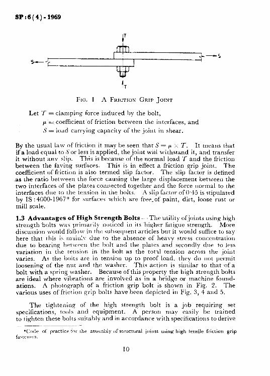
1.2 General Principles - In an ordinary bolted joint the force from one side is transferred to the other side through the interlocking and bearing ot the bolts. In a friction grip joint, however, the force is transferred by virtue of the friction between the interfaces. TO develop this friction a normal load is applied to the joint by using high strength bolts tightened to proof load. A study of Fig. 1 will make the point clear.
9
SP:6(4)-1969
-5
FIG. 1 A FRICTION GRIP hJ~~~~
Let T = clamping force induced by the bolt,
p = coefficient of friction between the interfaces, and
S = load carrying capacity of the joint in shear.
By the usual law of friction it may be seen that S = CL x 7. It means that if a load equal to S or less is applied, the joint will withstand it, and transfer it without any slip. This is because of the normal load T and the friction between the faying surfaces. This is in effect a friction grip joint. The coefficient of friction is also termed slip factor. The slip factor is defined
has the ratio between the force causing the large displacement between the two interfaces of the plates connected together and the force normal to the interfaces due to the tension in the bolts. ii slip factor of 0.45 is stipulated by IS :4000-1967” for surfaces which are free-of paint, dirt, loose rust or mill scale.
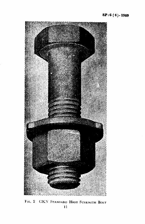
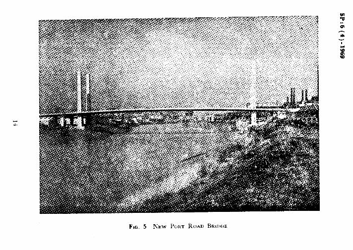
1.3 Advantages of High Strength Bolts-The utility ofjoints using high strength bolts was primarily noticed in its higher fatigue strength. More discussion lvould follow in the subseyuent articles but it wottld suffice to say here that this ir m:Cnlv due to the absence of heavy stress concentration due to bearing between the bolt and the plates and secondly due to less variation in the tension in the bolt as the total tension across the joiiit varies. As the bolts are in tension up to proof load, they do not permit loosening of the nut and the washer. This action is similar to that of a bolt with a spring washer. Because of this property the high strength bolts are ideal where vibrations are involved as in a bridge or machine found- ations. A photograph of a friction grip bolt is shown in Fig. 2. The various uses of friction grip ~bolts have been depicted in Fig. 3, 4 and 5.
The tightening of the hiah strength bolt is a job requiring set specifications, tonls and equipment. A person may easily be trained to tighten these bolts suitably and in accordance with specifications toderive
*C:ode 01‘ practice for the aswrnbly of structural ,joints using high tensile friction grip I-artCIlt’l s.
10
SP:6 (4)-]g6g
FIG. 2 GKN STANDARD HIGH STRENGTH BOLT
11

SP:6(4 )-1969
FIO. 3 DETAILS OF A JOINT IN A GOLIATH CRANK

SP:6 (4)-1969

SP:6 (4)-1969
a uniform performance. Because of the checks, calibrations, etc, there is very little chance to make an error. No special equipment like furnaces is needed on site. In the absence of sparks, fire hazards are totally eliminated. The noise level is very low ( as no hammers are needed ) which is of special importance in residential areas. The joints are permanent for all purposes and exhibit characteristics similar to riveted joints. The friction grip joint may be dismantled with ease. The fabrication is also faster as the tolerances between the diameter of holes and the bolt sizes may be larger. This is because the strength of the joint is derived from the friction and not from the bearing which calls for closer tolerances. The inspection of these ,join:s involves whether the surfaces have been cleaned suitably and whether the bolts have been tightened to the desired tension. This may be checked easily and corrections may be made simply by replacing the defective bolts.
1.4 Code of Practice - The provisions of IS: 8OO-1962” are generally applicable for the desi,qn nf ,joints with high tensile fi-iction grip bolts. The special provisions for the use of these bolts are covered in IS: 4000-19677.
2. DESXGN OF JOINTS
2.1 General - In the early stages of the development of the friction grip .joints, it was normal to design the joints by assuming the use of ordinary bolts or rivets and substitute them by high tensile bolts. Because of this practice all the inherent advantages of the bolts could not be fully utilized. However, in competitive spheres this was not much welcomed because of the higher cost of the high strength bolts. During this time, the research and development work was progressing. It lead to the formulation of the codes of practice.
The special l’eatllrcs of lligh tensile bolts are their frictional properties ill the joint by the virtue of applied preload in the form of tension in the bolts. ‘This fcatllrc: has made possible the use of fewer number of high tcansile l)olts than that of rivets or ordinary bolts.
2.2 Shear Connections-The formula S = p x 7 was established in 1.2 indicating the relationship between the shear carrying capacity and the normal load 011 the .joint. If there are Jv interfaces, the formula becomes S = AL/L x 7. Dividitrg this by a safety factor, we get the formula as give11 ill 4.3 of IS : 4000- 1967:.
*Code of plarticc> for llsc 01 sll~uctlllal steel in ( reuisad )
general building construction
fCotle of pmcticr fir the assembly of structural joints using high tensile friction grip fastemrs.
$Code of practicr &jr assembly Of structural joints using high tensile friction grip fastrnPrs.
15
SP:6 (4)-1969
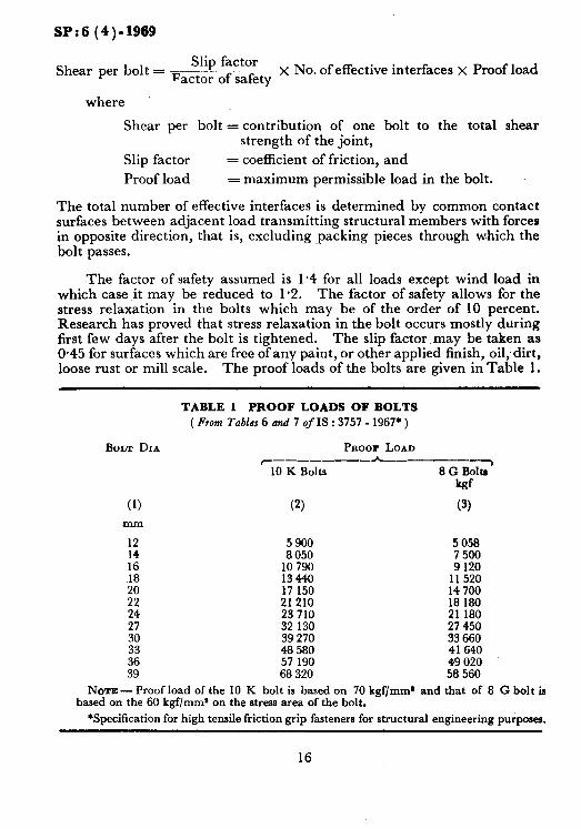
Shear per bolt = ~~ Slip factor
Factor of safety x No. of effective interfaces x Proof load
where
Shear per bolt = contribution of one bolt to the total shear strength of the joint,
Slip factor = coefficient of friction, and
Proof load = maximum permissible load in the bolt.
The total number of effective interfaces is determined by common contact surfaces between adjacent load transmitting structural members with forces in opposite direction, that is, excluding -packing pieces through w~hich the bolt passes.
The factor of safety assumed is I.4 for all loads except wind load in which case it may be reduced to l-2. The factor of safety allows for the stress relaxation in the bolts which may be of the order of 10 percent. Research has proved that stress relaxation in the bolt occurs mostly during first few days after the bolt is tightened. The slip factor, may be taken as O-45 for surfaces which are free of any paint, or other applied finish, oil;dirt, loose rust or mill scale. The proof loads of the bolts are given in Table 1.
BOLT DIA
(1) mm
12 14 16 18
;: 24
:;:
:: 39
TABLE 1 PROOF LOADS OF BOLTS ( From Tables 6 and 7 of IS : 3757 - 1967’ )
P~oor LOAD c------- *----_')
10 K Bolts 8 G Bolts kgf
(2) (3)
5 900 5 058 8 050 7 500
10 790 9 120 i3440 11520 17 150 14 700 21210 18 180 23 710 21 180
~32 130 27 450 39 270 33 660 48 580 41640 57 190 49 020 68 320 58 560
NOTE - Proof load of the 10 K bolt is based on 70 kgf/mm* and that of 8 G bolt is based on the 60 kgf/mms on the stress area of the bolt.
*Specification for high tensile friction grip fasteners for structural engineering purposes.
16
!%I’:6 (4)-1969
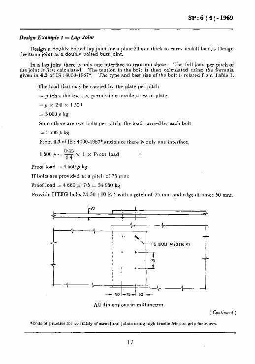
Design Example I - Lap Joint
Design a doubly bolted lap joint for a plate 20 mm thick to carry its full load. . . Design the same joint as a doubly bolted butt joint.
In a lap joint there is only one interface to transmit shear. The full load per pitch of the joint is first calculated. The tension in the bolt is then calculated using the formula given in 4.3 of IS : 4000-1967*. The type and best size of the bolt is related from Table 1.
The load that may be carried by the plate per pitch
= pitch x thickness x permissible tensile stress in plate
=p x 2.0 %, 1 500
= 3 000 p kg
Since there are two bolts per pitch, the load carried by each bolt
= 1 500 /I kg
From 4.3 ofIS : 4000-1967* and since there is only one interface,
0.45 1 500 /, = R x 1 x Proot load
Proof load = 4 660 p kg
If bolts are provided at a pitch of 75 mm:
Proof load = 4 660 x 7.5 = 34 950 kg
Provide HTFG bolts M 30 ( 10 K ) with a pitch of 75 mm and edge distance 50 mm.
,
n 1 All dimensions in millimetres.
( Cmlinued )
*Code ot practice for assembly of structural juinbs using high tensile friction grip fmtruera.
17

SP:6 (4)-1969
Design Example I- Lap Joint - Contd
The design of a double bolted butt joint is similar to the design of a lap joint except that there will be two interfaces to transmit the shear.
1 500 p = “;:‘~ x 2 x Proof load
Proof load = 2 330 p kg
If the bolts are provided with a pitch of 40 mm:
Proof load = 2 330 2: 4.0 =- 9 320 kg-
Provide HTFG bolts M 16 ( 10 K ) at a pitch of 40 mm.
I ,
+ Cl t I
-cd 40 _+ + ; + + .“-FG BOLT M16(10K)
c--t + ; + + -9-
A
All dimensions in millimetres.
18

SP:6 (4)-1969
Design Example 2 - Column Base Connections
A colrnnn f ICLR 200 ) carries a load of 25 000 kg. Design the base connection assuming chat the column end is not machined and the whole load is being transferred to ihr base by flano,e anel?s..
12 ,500 Load per cm of plate s 30-- = 416 kg
Bending moment in the gusset at the edge of flange of ISLB 200
416x 9.52 1 --
2~ = 18 800 kg.cm
18800 >lodulus of section required = m = 11.4 cm*
The depth of plate is fixed as 160 mm to accommodate the bolts.
Thickness of plate required = -i6r 11.4 x 6 _ 2.68 mm
Provide a plate of thickness 5 mm.
Maximum vertical shear in the gusset = 416 x 9.5 = 3 940 kg
Shear cm at the le\ cl 3940 0.75 7.25 x 12
per of base angle = I__--. x ----- x -. - -.---~~-- 0.5 x 9.33
= 63 kg/cm2
Total horizontal shear = 63 x 9.5 = 600 kg
Since the bolts are in single shear:
Proof load = ‘v = 1 860 kg
Provide HTFG bolts 12 M ( 8 G ) 2 in number on either side.
19

SP:6 (4)-1969
Design Example 3 - Moment Connection
Design a suitable moment connection to transfer a moment of 45 000 cm.kg from the top column to the column below.
,.---&3000 cm.kg
Assuming that the direct load is transferred to the lower colmnn by the Deb conncc- tions, the flange connections should be designed to transfrr the bending nlomrnt.
Shear on the bolts at each flange = c3te : 1 287 kg
The bolts are in single shear and the picking material does not ha\e any structural function.
0.45 :. ,-e x Proof load = 1 287
Proof load : 4 000 kg
Select HTFG bolts M 1’2 ( 8 G ) 4 in number at each flange.
20

SY<6(4)-1969
Design Example 4 - FIange Bolts of n Plate Girder
Total shear = 125 000 kg
Moment of inertia of the plate girder = 1 323 000 ems
The longitudinal shear ( q ) per unit cm of the-girder is given by the formula:
P .4 Y q = - kg:cm
I
where
P = -l’otal shrar in kg,
‘4 = Area of the element to be connected in ems,
1’~ Distance between the neutral axis of the section and the centre of gravity
of rhr element to be connected in cm,
I = Moment of inertia of the entire section in cm’,
125000 x 270 x 95 :.q= 1 323 000
= 2 420 kg’rm
Try HTFG bolt 51 22 ( 10 K ). Proof load = 21210 kg.
Shear carrying capacity of a pair of bolts
0.45 zzz 2 X - X 212io
1.4
5 13635 kg
p’tr), = !3635 = j.(; cm 1 2 420
Provide the bolts at a pitch of55 mm.
FG BOLT M22flOK) a55
All dimensions in millimetres.
21

SP:6 (4)-1969
Desim EXiW?Ude 5 - Column Bracket A bracket to a column is supporting a gantiy girder, as shown in the figure. The
reaction from the gantry girder is 28 000 kg at 350 mm from the centre of the column. Design the bolted connection for the bracket.
28 000 kg
ISMB 250
All dimensions in millimetres.
Assume the bolt pattern as shown in the figure. The bolts are in shear. In an arrangement like this it is possible to show that shear in each bolt
M _ z(x”+J’,
XT
where M = Bending moment,
x, y = Ordinates of bolts from the centre of gravity of the bolt groups, and r = Distance of the bolt in question from the centre of the bolt group.
( Continued )
22

SP:6 (4)-1969
Design Example 5 - Column Bracket - Contd
It is evident from this formula that the bolt furthermost from cg of the bolt group carries the maximum shear.
C ( xs +_ys ) = 4 ( 3.252 + 7s + 3.25s + 14s + 3.25’ + 21’) + 2 (3.25)’ = 2 890 cm’
Maximum shear = 14000 X 35 x 21.2
2 890 = 3900 kg
~ECCENTRICITI 350+ r-l
BOLT POSITION
All dimensions in millimetres.
The vertical of this shear 3 900 x 3.25
component = 21.2
= 600 kg
The horizontal component of the shear = 3900 x 21
21.2 = 3870kg
In addition to the shear due to the bending moment the bolts also carry the normal load.
14 000 Normal load on each bolt = 14 = 1OOOkg
Total vertical component of theirhear = 1 000 + 600 = 1600 kg
The resultant shear = 2/ ( 1600s + 3 870s ) = 4200 kg
From 4.3 of IS : WOO-1967*,
we have ‘2 x Proof load
:. Proof lb: = 42;.,x, la4
= 4 200
= 13 100 kg
Use HTFG bolts M 20 ( 10 K)
.&de Of DE3CtiCC for assembly of structural joints uslug high tensile Rlction grip tirsteners.
23

SP:6 (4)-1969
2.3 External Tension
2.3.1 The strength of a joint with high tensile friction grip (HTFG) bolts is developed as a result of th e clamping force induced in the joint. This clamping force is cattscd by the tension in the shank of the bolt tightened to its proof load.
In certain types ofjoints the external load acting parallel to the shank of the bolts increases tension in the bolts thtts reduces the clamping force. An example of such a loading is in the case of the dead erld ot a pressure vessel. When there is no internal pressure, the clampinri_ 1brc.e between the flange and the Ilange plate is fully effective. .As the internal pressure increases, the flange plate is pushed a\t:ay from tile flange introducing an additional tension on the bnlt shank. This tension, kno\<n as the external tension, reduces the ciamping fierce.
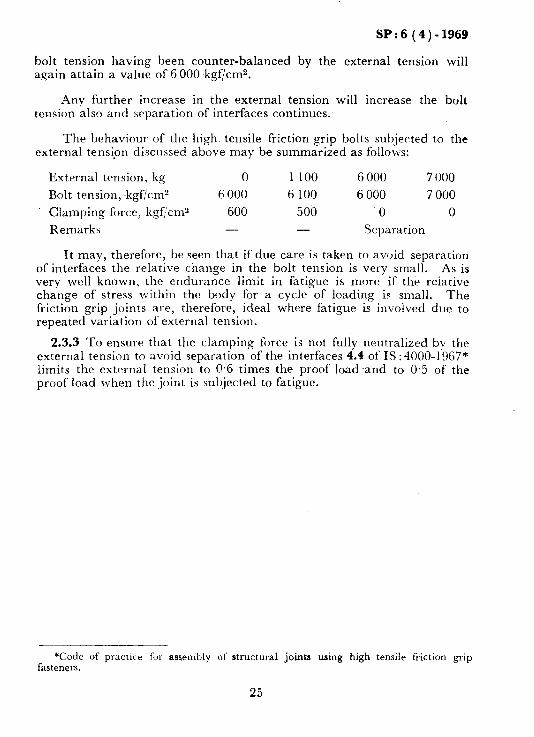
2.3.2 The behaviour of a joint subjected to external tension is intrrest- ing. Consider the joint in Fig. 6. The bolt is tightened to a pre-load of 6 000 kgf. Assuming the contact area of the plates per bolt to be 10 cm2
6 000 clamping force in the interface = -..- = 600 kgf/cm2
10
If the joint is subjected to an external tension of 1 t 00 kgf, reduc:tic,tt irt 1 100
the clamping force = - = II
100 kg/cm? (the area comprises IO cm2 con-
tact area and I cm’ bolt area). There will also be an itrcreaxe it1 ttte bolt tension by 100 kgl;‘cm2 to 6 100 kgf/cn?. reduced by 100 kgcc.m” to 500 kgf/cm?.
The clampitlg force u ill tjc
If, however, the external tension is increased to 6 000 kgf, tlte c.latrtpirlg force is completely neutralized causing separation of the interfaces. 1‘11(.
24
SP:6 (4)-1969
bolt tension having been counter-balanced by the external tension will again attain a value of 6 000 kgf/cm2.
Any further increase in the external tension will increase the bolt tension also and separation of interfaces continues.
The behaviour of the high tensile friction grip bolts subjected to the external tensipn discllcsed above may be summarized as follows:
External tension, kg 0 1 100 6 000 7 000
Bolt tension, kgf/cm’ 6 000 6 100 6 000 7 000
Clamping force, kgf,‘cm” 600 500 0 0
Remarks - - Separation
It may, therefore, be seen that ifdue care is taken to avoid separation of interfaces the relative change in the bolt tension is very small. As is very well known, the endurance limit in fatigue is more if the reiative change of stress within the body for a cycle of loading is small. The friction grip joints are, therefore, ideal where fatigue is involved due to repeated variation of external tension.
2.3.3 To ensure that the clamping force is not fully neutralized by the external tension to avoid separation of the interfaces 4.4 of IS :4000-1967* limits the external tension to 0.6 times the proof load and to 0.5 of the proof load when the joint is subjected to fatigue.
*Code of practice fur assembly ol’ structural joints using high tensile friction grip fasteners.
25

SP:6 (4).1969
Design Example 6 - Column Bracket
A bracket as shown in the figure carries a load of 20 tonnes. By resplying the force triangle it will be found that the horizontal member carries a load of ‘2&t thereby sub- jecting the bolts connecting it to the column flange to pure tension. It is required to design these bolts.
4
A V
20 000 e2
- 1500 ISMB 150
SECTION Ab
All dimensions in millimetres.
Providing an end plate and four bolts:
Tension per bolt = ‘2:s = 5 000 kg
The bolts are to carry external tension which is not repetitive. :. 0.6 x Proof load = external tension
Proof load = F-1 58yikkgg
Provide HTFG bolts Ml6 ( 8 G ) - 4 numbers.
26

SP:6 (4)-1969
Design Example 7 - Flange of a Gas Cylinder
The pressure in a gas cylinder of internal diameter 100 cm varies between 4.5 kgf/cm’ and 6 kgf/cma. It is required to design the flange connection.
BOLT M16(10K),9OFF
All dimensions in millimetres.
Total maximum pressure of gas on the flange
= Area of flange x Pressure
7T X 1002 =
4 x 6.0
= 47 000 kg
The bolts are in tension which is fluctuating between 4.5 and 6.0 kgf/cm*. The maximum permissible external tension should, therefore, be limited to 0.5 times the proof load according to 4.4 of IS : 4000-1967*.
0.5 x Total proof load = 47 000 kg
:. Total proof load = 94000 kg
Provide HTFG bolts M 16 ( 10 K) with proof load of 10 790 kg,
number of bolts required = 1. 790 !?e!??_g
*Code of practice for asembly of dnvzturd joiuts using high tensile friction grip fasteners.
27

SP:6 (4)-1969
~2.4 Combined Tension and Shear
2.4.1 General--Considerable research work has been carried out on the behaviour of high tensile friction grip bolts in joints subjected to a combi- nation of tension and shear. Such combination may be formed in joints connecting columns and beams, brackets, stringer beams to floor beams etc.
Experiments conducted for various combinations of tension and shear indicate that the curve for the relationship between shear and tension at failure is elliptical of the nature:
x = ratio of calculated shear on the bolt to the shear at failure,
“Y = ratio of the calculated tension on the bolt to the tension at failure, and
k = a constant dependent on the strength of bolt.
\‘alue of k is found to be 0.83 if the bolts fail in shank and 0.64 if they fail in threads.
2.4.2 The ultimate strength of the bolt given bv this formula increases with the grip of the bolt as the effect of shear loadmg on the shank bend- ing becomes predominant. Also, the formula indicates the behaviour of bolts at failure and, therefore, is not easily applicable to the normal design purposes. A simpler formula has, therefore, been specified in 4.5 of IS : 4000-1967* which reads as follows:
Calculated shear _ ___--. Slip-factor x No. of interfaces
$ Calculated tension x F
Proof load Factor of sarety
F= 1.2 when the tension is non-repetitive, or
= 1.43 wllfn the tension is repetitive.
*Code of practice fol. assmbly of structural joints using high tensile friction grip fasteners.
28

SP:6 (4)-1969
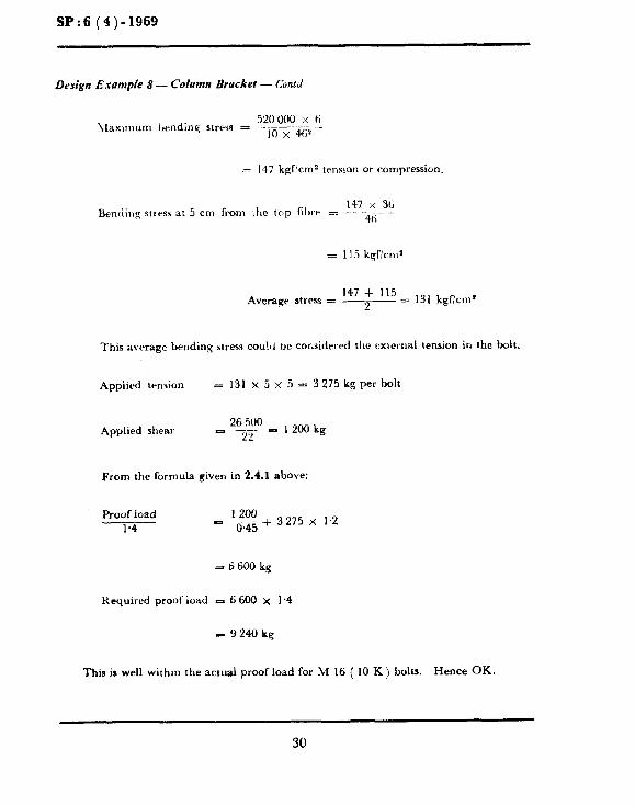
Design Example 8 - Column Bracket
A gantry girder transfers a load of 26.5 tonnes through a bracket with an eccentri- city of 19.5 cm. Design the bracket.
26.5 T
FG BOLT M16(lOK)
MS PLATE 10 mm THICK
All dimensions in millimetres.
Bending moment = 26.5 x 19.5
= 520 cm.t
Try HTFG bolts hf.16 ( 10 K ), 22 in number.
When there is no load on the bracket it is held on to the column by compression between the surfaces covered due to the bolt tension. This phenomenon, continues even when the load of 26.5 t, 1s applied since the joint will be designed for no separation criteria. The interface could, therefore, be considered as a plane in a monolithic beam of cross-section 10 x 46 cm.
( Confinued j
29
SP:6 (43-1969
Design Example 8 - Column Bracket - Conld
520000 x ti \Iaximum bending stress = .-
10 x 46%
;1 117 kgf’cms tension or compression.
147 x 36 Bending stress at 5 cm from Che trip filer z _ ---- --
46
z= 115 kgficn?’
Average stress = zl> = 131 kgficm’
This average bending stress cou!~l tie cor.sidelcd the external tension in the bolt.
Applied tension = 131 x5~5=3275kgperbolt
Applied shear 26 WO
- 717 B 1200 kg
From the formula given in 2.4.1 above:
Proof load 1.4
1200 - F45+ 3275 x 1.2
s 6 600 kg
Required proof load - 6 600 x 1.4
-924Okg
This is well within the actual proof load for M 16 ( 10 K) bolts. Hence OK.
30
,SP:6 (4)-1969
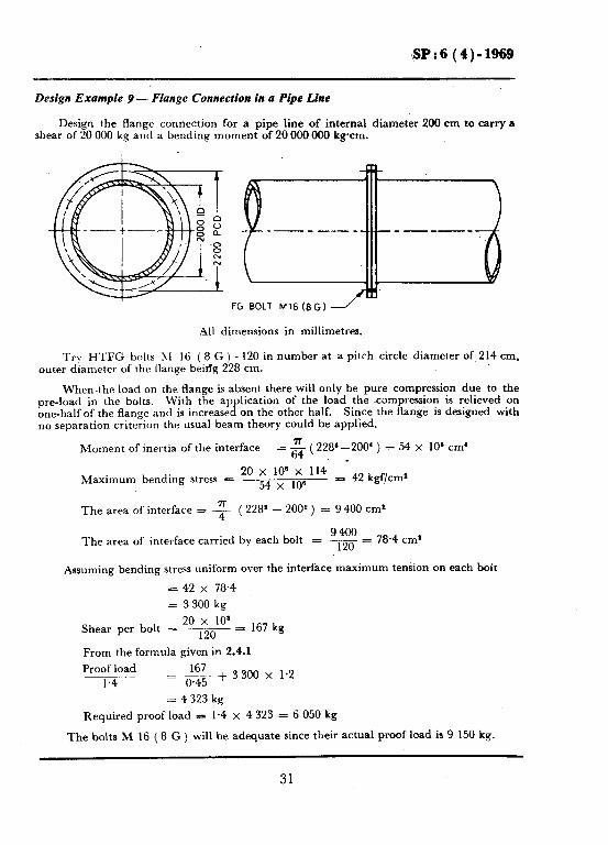
Design Example 9 - Flange Connection in a Pipe Line
Design the flange connection for a pipe line of internal diameter 200 cm to carry a shear of 20 000 kg and a bending moment of 20 000 000 krcm.
FG BOLT M16(8G)
All dimensions in millimetres.
Trv HTFG bolts ;\I 16 ( 8 G ) - 120 in number at a pitrh circle diameter of 214 cm, outer diameter of the flange beirfg 228 cm.
When the load on the flange is absent there will only be pure compression due to the pre-load in the bolts. With the application of the load the compression is relieved on one-half of the flange and is increased on the other half. Since the flange is designed with no separation criterton the usual beam theory could be applied.
Moment of inertia of the interface = & ( 228‘-200’ ) = 54 X 10’ cm’
Maximum bending stress = 20 x 10’ x 114
54 x 10’ = 42 kgf/cms
The area of interface = -F ( 228s - 200* ) = 9 400 cm*
9400 The area of interface carried by each bolt = 120 = 78.4 cm’
Assuming bending stress uniform over the interface maximum tension on each bolt
= 42 x 78.4
= 3 300 kg
20 x 10’ Shear per bolt = .--~ - = 120
167 kg
From the formula given in 2.4.1
Proof load -_ .- ‘?
1.4 = F45 + 3300 x 1.2
= 4 323 kg
Required proof load = 1.4 x 4323 = 6 050 kg
The bolts M 16 ( 8 G ) will be adequate since their actual proof load is 9 150 kg.
31

SP:6 (4)-1969
Design Example IO - Stringer Seam Connection
Two stringers. ISLB 250 and ISLB 350, are connected through cleats to thr \vrb of III,, main beam IS-LB 500. ISLl% 230 transmits a shear of 4 500 kg and a moment of 75 OW kgcm while a shear of 12 000 kg and moment of 350 000 kg.cm is transmitted bv 1SI.H 350. Design the connection.
The bolts may he divided into three groups, namely, A, B and C:. as shown in tile sketch.
Polar moment of inertia of the bolt group
= 4 ( 22 + 22 + 2* ) + 4 ( 22 +- 62 + lo2 !
= 608 cm* Distance of the farthrst bolt from the centre of gravity of the bolt group.
= 2/(22+1@,
= 10.2 cm
hlaximum shear in the bolt due to the moment = 350 on0 ” IO,:!
__- do8
= 5 870 kg
The horizontal 5870 x 10
component = IO.2
= 5 750 kg
5870 x 2 Vertical component = -,r = 1 150 kg
12 000 Vertical load carried by each bolt = -12 = I 000 kg
Total vertical shear =.= 1 150 + 1000 = 2 150 kg
Resultant shear = d (-~7~<2~1502) = 6 130 kg
32

SP:6 (4)-1969
Design Example 10 - Stringer Beam Connection - Contd
5750 kg
The bolts
From 4.3 0.45 xx2
are subjected to double shear.
of IS : 4000-19t57*,
x proof load = 6 130 kg.
:. Required proof load = 9 550 kg.
Provide HTFG bolts M 16 ( i0 K), 12 in number.
All dimensions in millimetres.
The bolt group B may similarly be designed to resist a shear of 45 000 kg and a bend- ing moment of 7.5 000 cm.kg. It will be found HTFG bolts M 16 (8 G) - 4 in number would be suitable. But for the sake of uniformity for both A and B groups M 16 ( 10 K) bolts may be provided.
Design of bolt group C:
The bolt group is to resist shear forces and bending moments acting on either side of the main beam ISLB 500. The moment from one stringer beam reduces the clamping force on its side and increases clamping force on the other side. The interface should also not slip due to the vertical shear. The worst case for the joint is, therefore, the applied
*Code of practice for as~emblv of structural joints using hightensile friction grip fasteners.
( Continued ) ---
33

SP:6 (4)-1969
Design Example 10 - Stringer Beam Connections - Contd
t
All dimensions in millirnetres.
bending moment and shear force on each interface. There will, however, be an increase in the tension in hllf the number of bolts when the moment is applied on both the sides. Since the external tension in the bolts is limited to 0.6 times the proof load and since the percent increase in the bolt tension is very small its effect may be neglected:
Bolts on the ISLB 250 side:
Shear = 45 000 kg Bending moment = 75 000 kg.cm.
Following the procedure given in Design Example 9,
75000 x 6 Maximum stress at the bolt = ___-
25x 16a -70 kg/cm*
Total tension in the bolt = 70 x 4 x 6.25 = 1 750 kg
4 500 Shear in each bolt = 16 = 280 kg
From formula given in 2.4.1, Proof load 280 ~~ ___
1.4 = W + 1 750 x 1.2 = 2 720 kg
Required proof load = 3 820 kg
Bolts on the ISLB 250 side,
Shear = 12000kg
Bending hloment
1 = 350 000 kg
The bolts may be designed adopting the same procedure as for the bolts on the ISLB 250 side.
Required proof load = 11 760 kg
from Taking into account the fact that the pre-load would increase because of moments
both sides and, HTFG bolts M 16-10 K (actual proof load 10 790 kg) may be used even though they are overstressed by 970 kg.
34

SP:6 (4)-1969
2.5 Moment Connections
2.5.1 Moment connections are characterized by their response to rotation to the applied moment. Rigid joints have very slight rotation due to applied load whereas flexible joints have more rotation for the same amount of applied moment. The flexibility of the joint depends on the total number of bolts used, type of the cleat and separation or otherwise between the cleat and the column in the tension zone.
The friction grip joint in bending is always designed so that there is no separation of the interface while being stressed. the bolt tension to 0.6 of the proof load.
This is done by limiting Thus, a friction grip joint exhibits
a joint more rigid than the ordinary bolted or riveted joints. However, this should be accompanied by a good design of connection cleats, which should be rigid enough to distribute the moment effectively over the bolt group without excessive deformation.
2.5.2 The Steel Structures Research Committee (UK) have conducted research work on the behaviour of various moment connections. Their recommendations for semi-rigid design draft rules for design are given in Appendix A of IS : 800-1962”. Table XXII of this appendix gives sizes of high strength bolts for various classes of moment connections.
2.5.3 The moment may induce either. tension or shear depending on the \<ay the bolts are placed. If there is only shear one should check that there is adequate factor of safety against slip. For this, the formula in 4.3 of IS: +OOO-1967t needs to be apphed. If the bolts are such as to induce tension in them due to moment, the tension on the bolt should first be calculated assuming that there is no separation at the interface. This tension should then be limited to 0.6 of the proof load to ensure that no separation takes place. M’here a shear is existing in addition to tension, the combined effect should he considered as shown in Design Examples 7, 8, 9 and IO.
2.6 Repeated Variation of Forces
2.6.1 The reduction of the strength of the structural joint and a member which is subjected to a cyclical loading depends very much, interalia, on the probable zone of higher stress concentration and the range of the induced stresses. The friction grip joint possesses special properties by virtue of its mechanism whereby the zone of higher stress concentrations are eliminated and the range of variation of the stress within the bolt and joint material is reduced for any given applied load cycle.
*Code of practice for use of structural steel in general building construction (revised). tcode of practice for assembly of structural joints using high tensile friction grip
fasteners.
35

SP:6 (4)-1969
2.6.2 In friction grip joint, the bolt does not bear against the holes in the plates to react the applied load. This avoids the heavy stress concentration that occur in ordinary bolt and rivet due to slip and bearing against plates. Further, as all the load is transferred by friction; shear, brarlng or bending stresses are not present in the bolt. Slight variation in the axial stress may exist due to Poisson’s effect but this effect will be comparatively small. As detailed in 2.3 on joints subjected to external tension the actual variation of the axial stress of the bnlt is much smaller than the variation of the external tension expressed as percentage. This is because the whole of the~joint acts monolithically to react the tension. Also, the high clamping force tends to distribute the applied load over a relatively large area there- by reducing the range of the induced stresses. Furthermore, repeated variation offorces tends to loosen the ordihary nuts. In a high tensile bolt the nuts are held in position by the reaction against threads Lvhich are similar in effect to a bolt tightened using a spring washer.
2.6.3 It will be thus seen that high strength bolts are especially suitable for the conditions where repeated reversals of load are encountered as in roadand railway bridges, gantry girders, machine foundations, etc. A great deal of research has been done on this property of the friction grip bolts. It has been shown that the fatigue strength of the friction grip joint is about 25 percent greater than that of the ordinary riveted joint. It i-s for this reason that IS : 4000-1967* does not reduce the working stresses for joints subjected to repeated variation of loads except the connections subjected to external tension. In such a case there will be sliaht lrariation in the axial stress, and the maximum permissible external tension on any bolt is limited to 0.5 of the proof load.
3. FABRICA-ilON
3.1 General-As indicated elsewhere, the characteristic of the friction grip joint depends on the proper clamping force induced by the high tensile bolts. This should correspond to the proof load according to the grade and the stress area of the bolt and should be within the permissible limits of variations. The permissible limits have not been specified in IS : 4000- 1967* as the measurement of the tension in all the bolts by direct method is not feasible on site. Instead, it specifies t\vo well-known methods, th0uF.h indirect, of achieving the desired effect and details the methods of quality control.
The indirect methods are:
a) torque control method, and
b) part turn method.
*Code of practice for assembly of structural joints using high tensile friction <lip fasteners.

SP:6 (4)-1969
These methods will achieve the desired effect with a variation of i 15 to 30 percent. A greater variation due to these methods, however, may contribute to the factor of safety against slip as the zero setting is invariably kept on the higher side.
Recently somewhat direct methods have been introduced. They are:
a) load indicating bolt, and
b) load indicating washer.
These two methods give results within f 6 percent.
The qualitv control on site is effected by the regular calibration of the torque spanner ‘in case it is used. Subsequent to that there is no visual check or inspection possible except that some bolts may be checked by re- tightening with the help of a calibrated spanner. Other methods visually indicate the final state of the bolt or the nut thus making the inspection much easier. Apart from these methods of introducing the desired preload in the bolts, it is necessary to control the coefficient of friction of the interfaces. In IS :4000-1967* the coefficient of friction is assumed to be 0.45 and a suitable criterion is laid down to achieve this.
In the subsequent articles the methods of tightening the bolts and the assembly of the joint will be described in detail.
3.2 Torque Control Method
3.2.1 General-The method is based on the linear relationship between the torque necessary to turn the bolt and induced tension in the bolt up to the proof load. After the proof-load, there is very little increase in the tension with the applied torque.
The relationship between the torque and the tension may be expressed as:
M=K-TD
where
M = applied torque,
ir = proof load,
D = nominal diameter of the bolt, and
K = a non-dimensional torque coefficient.
The constant K is a function of the inclination of the threads, co- efficient of friction at the threads and also at the nut and the washer. The value of K may be taken as 0.1~5 if the bolt is slightly lubricated and as 0.25 if it is rusty.
*Code of practice !;JY assembly of structural joints using high tensile friction grip fasteners.

SP:6 (4)-1969
Spanners called ‘Torque Limiting Spanners’ or the hand wrenches and impact wrenches working on the air pressure are used to apply the predetermined torque to the bolt. They are so designe$ that they are unable to apply any more torque than the preset value.,..This limiting value is set by the use of the formula and then calibrated to give a more precise setting. ‘rhis is done by tightening a sample bolt against a load cell or similar apparatlls (see 3.2.2 J. Tile load cell is designed to sho\L’ the direct tension induced in the bolt. The torque spanner is ad.justed to produce a tension 10 percent higher than the proof load of the bolt. The bolt used for calibration is not to be used elsetvhere as a friction grip bolt.
Such calibration is made once or more per shift depending on the 1vnr.k load, It is also necessary when the condition of the bolt, size, length, grade, etc, are changed. It may, therefore, be necessary to keep differently calibrated equipment ready for speedy work.
The inspection of the bolt tightened by this method is done by select- ing suitable sample of bolts and finding the torque required to retighten them further by using a hand wrench or an impact wrench. If the torque required is found to be below the requirement, every bolt in the hatch sholrld be examined and further tightened. The quality control also incltldes frequent dalibration of the tool used.
The advantages and disadvantages of the method may be summarized as follows:
a) b)
The limit of variation is between & 15 to 30 percent.
Re-calibration is necessary for different sizes and grades of tile bolts.
cl On a job whew different grades and sizes of the bolts are used tile method becomes unwieldly.
d) There is no visual check on the completion of the joI>.
e) Special tools are necessary which may not be easily available.
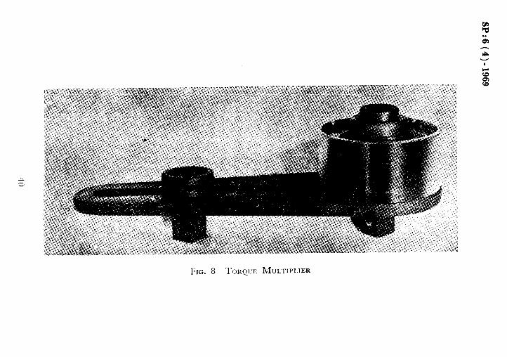
3.2.2 E+prn~~t- The torque control method requires a torqlte spanner (.SeP Fig. 7). The torque spanner is adjusted to predetermined torque at the handle end. The spanner works up to this set torque and collapses if torque to he reacted exceeds. The collapse of the spanner is both seen and felt. \Vhen every large bolt sizes are used it is necessary to apply heavy torques. It may lead to the danger of straining or slipping of the personnel. This difficulty is avoided by using torque multipliers (see Fig. 8) to give a mechanical advantage up to 25 : 1.
38

7 TORQUE SPAI
39
SP:6(4) -1969
VNER

SP:6 (a)-1969
The calibration needed may be determined by the use of the following meters:
a) Static torque meter (see Fig. 9). This checks the accuracy of the setting of the predetermined torque on the torque spanner;
b)
FIG. 9 STATIC TORQUE METER
Torque tension meter. This instrument enables the torque/tension ratio of many standard fasteners to be quickly obtained and easily read from two dials; the variables that may prevent accurate calculation of the bolt tension are automatically accounted for in this calculation; and
41

SP:6 (4)-1969
c) Bolt load meter ( s&e Fig. 10 ). This equipment is designed to measure the bolt load only, which enables nut runners, impact wrenches or torque spanners to be calibrated directly to give the desired tension in the bolt. Torque measurement, which is an intermediate step, may be eliminated. Where torque recommend- ations are still required to be satisfied, a sample of six fasteners may be selected at random and the torque to which they have been tightened found out by retightening them by a calibrated spanner. Use of torque spanner and torque multiplier is shown in Fig. 11.
FIG. 10 BOLT LOAD METER

SP:m6 (4)-1969
3.3 Part Turn Method-- \l’hat is essentially required in a friction grip joint is preload in the bolt and the accompanying clongatiou of the bolt. This may be achirvcd bv turnin, m the nut after the I)olt is made just tight. The method based on tl;is principle is called ‘ Part Turn Method’.
In this method the illterfaces are cleaned of all dirt, l>urrs, loose mill- scale, etc, by using suitable tools. The membrrs fornG,lg the joint are then carefully broIlgIlt toqrthcxr lvithout using ally forccx or making llndue deformation. The irLtrrfaces are again inspected to see whether any loose particles like that of sand, metal, etc, are lodged lvithin or not. ‘l’he LoIts are then introduccad and subjected to preliminary tightenin,g so that they are just tight and it becomes impossil)le to turn -them any further l)y fixlgcrs. If power operated wrenches are used, they are set to 5 percent of the total torque as required by the torque control method. This ci percent is taken as ‘a just tight bolt condition’ before giving the final turn as specified.
After this mark is made on the nut and the protruding thread portion of the bolt to record the initial position, the nut is tightened SO that the
relative turn corresponds to that specified in Table 2.

SPr6 (4)-1969
TABLE 2 FINAL TIGHTENING OF BOLTS
( Clause 3.3 )
All dimensions in millimetres.
NONINAL DIAMETER GRIP OR BOLT FOR ROTATION OF THE NUT OF BOLT ( RELATIVE TO THE BOLT SHANK )
---------- -A--------_--_~
Not Less Than l/2 Turn Not Less Than 314 Turn
(1) (2) (3)
M 16 up to 114
M 20 $3 ,, 114 Over 114 to 216
M 22 114 114 280 1. >, ,, ,,
M 24 16.5 165 360 >, 1, ,, ,,
M 27 165 165 360 9, ,, ,, ,,
M 33 165 165 360 ,, ,. ,, ,,
As will be seen, this method does not require any sophisticated tools to achieve a preload as ordinary spanners may be used for tightening. The method gives freedom to engineers on site to choose any lubricant or the condition of the bolt without affecting the final result. The inspection is also made easy as this need.s to check the final position of the marks previously made on the nuts and the bolts. However, the efficiency of this method very much depends on the initial condition of the joint before giving the final turn.
Tightening the bolts by a torque wrench set to 5 percent of the total torque is to some extent satisfactory. In addition to this, one should make sure that there is no extraneous matter within the joint which would break or yield plastically as further load is applied. In spite of this, the final preload depends on the condition of the surface and gaps between the components. Therefore, this method tends to give the percentage variation in the induced load somewhat greater than the torque control method.
3.4 Recent Developments in High Strength Bolts
3.4.1 General -The methods described in 3.2 and 3.3 are indirect methods of achieving the bolt tension. They require some form of supervision and special tools as in the case of a torque control method. With this basis, the variation in the results achieved is between 15 to 30 percent.
With this background, GKN Bolts and Nuts Ltd, UK; Cooper and Turner Ltd, UK; and others developed suitable bolts and washers to ensure a correct tension with little variation.
44

SP:6 (4)~1969
3.4.2 Load Indicating Bolt-This is developed by GKN Bolts and Nuts Ltd, UK. The head of the load indicating bolt is so shaped that before tightening it makes contacts with the steel with its four corners only. This leaves a gap between the steel and the underside of the bolt head. As the bolt is tightened, the part of the bolt head yields and causes a gradual closure of this gap. These experiments show that to ensure a correct bolt load it would only be necessary in practice to make sure that the widths of the gaps under the head were reduced to less than 0.8 mm. This may be done visually or by using a simple feeler gauge ( see Fig. 12 ).
3.4.3 Load Zndicnting ll’asher-This special washer is developed by Cooper And Turner Ltd, UK (see Fig. 13). The washer has protrusions on its surface. When it is fitted under the bolt head, there is left a gap between the general surface of this washer and the underside of the bolt head. The bolt is then tightened until the gap is reduced to an average of 0.4 mm as measured hv a feeler gauge. If the gap is inadvertantly closed to less than that ‘it is to be allowed to remain so and on no account adjusted by slackening the mkt.
3.4.4 Apart from the above mentioned methods GKN Bolts and Nuts Ltd, have developed a torshear bolt. The correct tension is achieved by a grooved extension machined to a calculated depth which shears off when the correct tension is applied preventing further tightening. This ensures that the correct tension is automatically applied and makes inspection easy and visual. The bolt needs a special tool for tightening.
3.5 Assembly of Join-
3.5.1 Bolt ,~izrs-Once the bolt diameter has been decided upon it is necessary to calculate the length of the bolt for ordering the material from the suppliers. The length of the bolt is given by the following formula:
1=Grip+m+t+3@
where
I= required length of the bolt,
m = thickness of friction grip nut based on ‘S’ grade finish as defined in IS : 3757-1966*,
t = the value of maximum negative tolerance on bolt length applicable for individual diameters, and
p = thread pitch (3p is meant to cover bolt end pointing).
*High-tensile friction grip fasteners for structural engineering purposes.
45

SP:6 (4)-1969
Fm. 12 GKN LOAD INIXATING BOLT
46

SP:6 (4).1969
Preferred length ~ tliarllc~~er ~r,:lll)il~tions are given in Tal,le 3. The t’ollo\vitl,q taI)Ie qivt,s t11c: lerlgth to be added to the grip length to
get the overall length of thr bolt. ‘I’his table can be used instead of the I~orrnula give11 almve. Tlris does 11ot provide for thickness of washers. ‘I’hickness of \vashers if’ used should he included in the grip length. The tal)le does not al 101~ for the \.ariation in the grip lengrh.
Bolt Size .4tld to (:ril, bolt ,Si.:e z lrld to Grif)
12 17 27 34 16 ( ‘1
:s 30 38
20 33 40 22 29 36 44 24 31 3)) 46
‘I’o be preclsc one should allow for both positive and negative tolerance in the plates in the grip of the joint. It1 order to allow this, the grip
47

SP:6 (4)-1969
length should be increased. by the positive tolerance and the threaded length should be increased by the difference between the negative and positive tolerance. However, in practice it is rare that a joint would consist of all members with the tolerance on one side only. As such the sum of the thickness of each member would neutralize the positive and negative tolerances giving the grip with much less variation. If in any special case the structural members are having tolerances on one side only, the designer will have to order the bolts as specials having longer threads.
TABLE 3 PREFERRED LENGTH DIAMETER COMBINATIONS FOR BOLTS
( Clause 3.5.1 )
LENGTII E (J17) Ml2 Ml6 M20 M22 M24 M27
MU
30 31.0 29.0 x
35 36.5 34.0 x
I.0 41.5 39.0 x
45 46.5 44.0 x
50 51.5 49.0 x
55 56.5 53.5 x
60 61.5 58.5 x
65 66.5 63.5 X
70 71.5 68.5 Y
75 76’5 73.5 --
80 81.5 78.5 -
90 92.0 88.5 -
100 102.0 98.5 -
110 112.0 108.5 -
120 122.0 128~0 -
130 131.0 128.5 -
140 142.0 138.0 -
150 152 0 148.0 -
160 162.0 158.0 -
170 172.0 168.0 -
180 182-O 178.0 -
I’:0 192.0 187.5 -
200 202-5 197.5 -
- - - -
x -
x -
x -
X X
x X
X X
X X
X X
X X
X X
X X
- X
- X
- X
- -
- -
- -
- -
.- -
- -
- - - - - -
X
X
X
X
X
X
:<
X
x
x -
-
-
-
-
- - - - - - -
X
x
X
X
X
X
X
X
X
X
X
-
-
-
-
-
- - - - - - - -
X
X
X
X
X
X
x
X
X
X
X
-
-
-
-
M30 h433 IL136 M39
- - .- - - - -- - - -- - - -- - - __ - - - - __
* - -- x - --
X X x x
X X x x
X X X x
x X x x X x X x X X A x X X x x
- X x x - X x x - X x x - X x x
3.5.2 Holes in Members- In IS :4000-1967* it is specified that all the holes shall be drilled and burrs removed. Where the number of plies in the
---- *Code of practice for assembly of structural joints uing high tensile friction grip
fasteners.
48

grip does not exceed three, the diameter of the hole shall be 16 mm larger than that of the bolt. Where the number of plies exceed three, the diameter of the holes in the outer two plies shall be as above and the diameters of the holes in the inner plies shall be not less than 1.6 mm and not more than 3.2 mm larger than those of the bolts.
SP:6 (4)-1969
If it is necessary to drift the holes, it shall be done so as to prevent distortion of the metal. If the holes need enlargement it shall be done by reaming provided the requirement of the maximum diameter is adhered to. If the holes are badly matched the members shall be rejected. But in no case the bolts shall be driven.
3.6 Preparation of Surfaces -TO develop the desired friction, the interface should I)e fret from all millscale, oil, paint, lacquer, galvaniz- ing or aluminizing rir similar finishes. In addition to this, there should be no gasket or similar material sandwiched between the plates. This will enstIre that the desired coefficient of friction is developed and that there is no comparatively weak material which would deform by sliding or get com- pressed under the load. It may be noted that IS : 4000-1967” does not allow for painting even for protection against corrosion. If the steelworks need to be supplied painted in shop, the contact surfaces should be masked. In USA, research work is in progress to evaluate the performance of the con- tact surfaces to lvhich a thin primer is applied immediately after grit blasting. It is learnt that the primer does not lower the coefficient of friction.
Therefore, the only way to protect the steelworks is to clean the inter- face and bolt them tightly, wirebrush the completed assembly and apply the paint.
It is obvious that cleaning the interface improves the efficiency and reliability of the joint. This may be done by:
aj removing traces of oil, chemically, if necessary;
b) stripping the paint; and
c) wirebrushing or grit blasting the surface to remove all loose material.
Among these, grit blasting improves the coefficient of friction of all the interfaces and eilectively remove a!1 the traces of oil and paint if still persistent after stripping. It consists of blasting the surface with abrasive material accelerated to a high velocity by the pressure of air or a rotating wheel. In some cases, a suspension of the abrasive in water is used which IS then accelerated by using high pressure air.
*Code of practice for assembly of structural joints using high tensile friction grip fasteners.
49

SP:6 (a)-1969
Preliminary tests lx-ere conducted by Aletallisation Ltd (UK), on sprayed friction grip joints. The tests indicated that:
a)
b)
c)
Galvanizing and ~painting should be avoided,
Freshly sprayed coating of zinc and aluminium increased slip factor well above the level normally required, and
In a second series of tests the structural members were subjected to weathering for three months. The tests indicated that slip factor does not fall helo\\ the desired level after lveathering.
3.7 Procedure for Tightening - If due care is taken in the lvorkmanship while manufacturin= the members, it should be easy to assemble the joints. Such a joint may be held in position using a few ordinary or high strength kJlt.% If lligil strength bolts ;YC used, they should not be included in the final assembly. After this temporary assembly, the bolts should be replaced by high strength bolts. \Yashcrs are introduced under the nut or the bolt head lvhichever is being turrlc-cl, if tightening is done by torque control method. Bcvellccl ~vashcrs are used to compensate for the lack of parallelism if the slope is more than 1 : 20. The bolts are tightened using a suitable method from the ceiitre of the bolt group outwards.
If high strength bolts get slackened off for any reason they should be cliscarded. If, however, load indicating bolts or washers are used, they may be re-tightened to the desired gap.
On no account the bolts should be slackened purposely, that is, if the desised tension is exceeded or if the gap was closed too much.
3.8 Inspection
3.8.1 Bolts, Nuts and Washers-Samples of the bolts are taken and tested for proof load in accordance with IS : 3757-1966*.
3.8.2 Interfaces of Structural Members -The holes should be carefully checked for burrs, tolerances and physical damage. The interface should be checked to see that it is according to requirement, that is, free from oil, paint, etc. In partial assembly there should be no gaskets, grit or other weak material.
3.8.3 Equipment - The torque limiting spanner should be checked for calibration. The method adopted for calibration itself should be checked,
3.8.4 Inspection after Tightening the Bolts-The mode of inspection varies according to the method of tightening and the type of the bolt used.
*Specification for high tensile friction grip fasteners for structural engineering purposes.
50

SP:6 (~4)-1969
3.8.4.1 Torque control Inethod--Sample bolts should be tried for re- tightening to see whether they are undertorqued.
3.8.4.2 Part turn method- The inspection will include checking the final turn as indicated by the displacement of the original marks on the nut and the bolt shank.
3.8.4.3 Torshear bolt-The bolt shank should be broken off at the pre- determined location on the shank.
3.8.4.4 Load indicating bolt or a washer-The desired gap should be checked by using feeler gauges.
3.9 Sampling - If the number of joints is too large it is not convenient to check all of them. It is, therefore, necessary to select some.of them at random from each batch. The batch means the group of joints with identical conditions regarding tightening. Therefore, the batch should consist of the amount of work done by one gang of men using the same tool with single calibration and done in one unit time, say, a day. Out of such a batch the inspector should select at least one-third joints at random. If each joint is numbered, he may take the help of the tables of random numbers to select them. It is unlikely that the total number of joints in a sample will constitute a large amount of work for inspection. However, if it is found to be so because of a consistantly large volume of batch, it will be useful to use double sampling technique wherein the preliminary sample is small and the result of which guides the inspector to reject all the batch as below standard,or take a further sample, if necessary.
51

SP:6(4)-1969
COMPOSITION
APPENDIX A ( see Foreword )
OF STRUCTURAL ENGINEERINti SECTIONAL COMMITTEE ( SMBDC 7 ), AND OF PANEL FOR CODE OF PRACTICE FOR USE OF HIGH TENSILE FRICTION GRIP
FASTENERS ( SMBDC 7/P 12 )
Structural Engineering Sectidnal Committee, SMBDC 7 .
Chaitman Rtprasanting Drnsrczo~ STANDAEDS ( CIVIL ) Ministry of Railways
SHRI L. N. A~RAWAL Industrial Fasteners Association of India, Calcutta SHBI M. M. MUEAXKA ( Altanatc )
Saar B. D. AEUJA SH~I P. C. JAIN (Rltematc )
National Buildings Organization, New Delhi
SEBI P. C. BEA~IN Ministry of Transport & Communication, Department
SEBI S. R. CH~KBAVABTY
of Transport ( Road Wing ) Central Engineering and Design Bureau, Hindustan
Steel Ltd, Ranchi SEBI P. D. DFIABWABKAB ( Altmutr )
SERX D. P. CHATTERJEE Inspection Wing, Directorate General of Supplies & Disposals ( Ministry of Supply, Technical Dcve-
Dn P. N. CEATTEII JEE lopmmt of Materials Planning )
DB P. K. CROU~HURI Government of West Bengal Bridge & Roof Co ( India ) Ltd, Howrah
SHRI A. SEN Gnpra ( Altemstc ) DR P. DAYARATNAM
SHBI D. S. Dssnr Indian Institute of ‘1 CChnology, Kanpur
SEXI M. DIXAR M; N. Dastur & Co Private Ltd, Calcutta Braithwaite & Co ( India ) Ltd. Calcutta
D~ECTOR ( DAIUS I ) Central Water & Power Commission ( Water Wing ), Nrw Delhi _._.. -- __._
SERI B. T. A. Snoax ( Alternote ) Soar M. A. D’souza
SHRI J. S. PINTO ( Aftemntc ) Bombay Municipal Corporation, Bombay
EXECUTIVE ENOINEEI:. ( CENTRAL Central Public Works Department, New Delhi STORES DN No. II )
SHRI W. FEWANDES Sam P. V. NAIK ( Alttmatc )
Richardson & Cruddas Ltd, Bombay
SERI SAILAPATI Gnpri ’ Public Works Department, Government of West
Smr G. S. IYER Da 0. P. JAIN JOINT DIRECTOR STANDARDS
(B&S) DEPUTY DIRECTOR STAND-
Bengal The Hindustan Construction Co Ltd, Bombay Institution of Engineers ( India ), Calcutta Ministry of Railways
ARDB’ ( B & S )-II ( .~ttefm.?tc ) Sam Oar KHOSI.A
Sanr S. N. SINOJI ( Alternate ) Electrical Manutacturing Co Ltd, Calcutta
( ~onrmurd on pop 53 )
52

SP:6 (4)-1969
21 funbers ~Refiresenting
Pr:or: K. D. MAFIATAX Engineer-in-Chief’s Branch, Ministry of Defence Pnoa P. V. P.+w \I1 ( ‘Iltenlnie)
SIIHT P. K. M ~J,LICI( Burn & Co Ltd, Howrah Snnr A. P. KhYAT. ( Allrmnte)
Suu1 A. Ii. MlTl:4 Hindustan Steel Ltd, Durgapur SHRI K. V. Bn.ssr;s1! RAO
PAXTCT.V ( .4//WlZ& ) sirnr II. G. r‘\l,arlc Irrigation & Power Department, Government of
Maharashtra SARI B. K. PANTHARY Indian Roads Congress, New Delhi
SNRI B. BALWANT RAO ( Al/ernate) Pnor G. S. RAMASWA~IY Structural Engineering Research Centre ( CSIR ),
Roorkee Dn s. Nnrra111 R.&o (.4/fernate)
Dn B. R. SEN Indian Institute of Technology, Kharagpur Smnr P. SFN GUPTA Stewarts & Lloyds of India Pvt Ltd, Calcutta
SHI~I M. M. GHOSJ~ ( Alt~mate) SfrIu I;. 1’. SWTTY Central Mechanical Engineering Research Institute
( CSIR ), Durgapur Srrnr S. K. GHOST ( Alternnte)
PROF P. K. sosl Jadavpur University, Calcutta SL?PERlNrENDINa ENQINBER Government of Tamil Nadu
( PT,~SNINQ & Dxsrcv CIRCLE ) EXWUTIVE ENQINEWI< (BUIL-
DNO CWTRE Drvlsros) (.Ilternate) MAJ R. P. E. VAZIF~AR Bombay Port Trust, Bombay SHR~ M. N. V~NKATICSAN Central Water & Power Commission (Power Wing),
New Delhi SHRI P. V. N. IYzNGAR (z‘!hrnnte)
ST~RI R. K. SRIVASTAVA, Deputy Director ( Strut & XIet )
Director General, IS1 ( Ex-qf&io Member )
SHRI 11. s. NAQ.4R.4J
Assistant Director ( Strut & Met ), IS1
Panel fcr Code of Practice for use of High Tensile Friction Grip Fasteners, SMBDC 7/P12
Convener
SHRI P. K. MALLICK Burn & Co Ltd. Howrah
Members
SHRI J. CIIATTERJEE JOINT DIRECTOR STANDARDS
(B&S)
Braithwaite & Co Pvt Ltd, Calcutta Ministry of Railways
SIIRI V. KAPOOR PKOF P. V. PAWAR PROF G. S. RAMASWAMY SHRI C. H. SHAH
Guest, Keen, Williams, Ltd, Calcutta Engineer-in-chief’s Branch, Ministry of Defence Structural Engineering Research Institute, Roorkee Garlick & Co Pvt Ltd, Bombay

BP:6 (4).1969
APPENDIX B ( see Foreword )
INDIAN STANDARDS AND OTHER PUBLICATIONS OF ISI RELATING TO STRUCTURAL ENGINEERING
ISI has so far issued the following Indian Standards in the field of production, design and utilization of steel:
Structural Sections:
IS : 808 - 1964 Rolled steel beam, channel and angle section ( revised)
IS : 811- 1965 Cold formed light gauge structural steel sections (revised)
IS: 1153-1967
IS: 1252- 1958
KS: 1730- 1961
IS: 1731 - 1961
IS: 1732: 1961
IS : 1852 - 1967
IS: 1863- 1961’
IS: 1864- 1963
IS: 2314- 1963
IS:2713- 1964
IS: 3443- 1966
IS : 3908- 1966
!S : 3909 - 1966
‘S: 3921- 1966
S:3954- 1966
S:3964- 1967
S:5384-1969
Hot rolled and slit steel tee bars (revised)
Rolled steel sections bulb angles
Dimensions for steel plate, sheet and strip for structural and general engineering purposes
Dimensions for steel flats for structural and general engi- neering purposes
Dimensions for round and square steel bars for structural and general engineering purposes
Rolling and cutting tolerances for hot-rolled steel products ( revised )
Dimensions for rolled steel bulb plates
Dimensions for angle sections with legs of unequal width and thickness
Steel sheet piling sections
Tubular steel poles for overhead power lines
Crane rail sections
Aluminium equal leg angles
Aluminium unequal leg angles
Aluminium channels
Hot rolled steel channel sections for general engineering purposes
Light rails
Aluminium I-Beams
54

SF’:6 (4j-1969
Codes of Practice:
IS: 800- 1962 Use of structural steel in general building construction ( ?Wiscn )
IS : 801- 1958 Use of cold formed light gauge steel structural members in general building construction
IS : 802 ( Part I ) - 1967 Use of structural steel in overhead transtCssion line towers : Part I Loads and permissible stresses
IS: 803- 1962 Design, fabrication and erection of vertical mild steel cylindrical welded oil storage tanks
IS : 805 - 1969 Use of steel in gravity water tanks IS : 806 - 1968 Use of steel tubes in general building construction ( revised) IS : 807 - 1963 Design, manufacture, erection and testing (structural
portion ) of cranes hoists IS : 3177 - 1965 Design of overhead travelling cranes and gantry cranes
other than steel work cranes IS: 4000- 1967 Assembly of structural joints using high tensile friction
grip fasteners IS : 4014 - ( Part I ) - 1967 Steel tubular scaffolding : Part I Definitions and
materials IS : 4014 (Part II ) - 1967 Steel tubular scaffolding: Part II Safety regu-
lations for scaffolding IS : 4137 - 1967 Heavy duty electric overhead travelling cranes including
special service machines for use in steel works
Handbooks
Handbook for structural engineers : 1 Structural steel sections Handbook for structural engineers : 2 Steel beams and plate girders Handbook for structural engineers z, 3 Steel’columns and struts
General
IS: 804- 1967 Rectangular pressed steel tnnks (/cc&i)
SP:6 (4) -1969
APPENDIX C
( see Foreword )
USE OF DIGITAL COMPUT-ERS FOR DESIGN OF JOINTS
The use of computers wil! Freatly simplify the procedure if the joints to be designed are of the repetitive nature. For example, in a multi-storey building most of the joints will be of column-to-beam type with applied moment and shear. Such joints would occur in multitude and would recluire too much of time in the design offices.
The use will of course introduce some form of restriction of the trivial nature like the total number, maximum size and general arrangement of the bolts. For example, the restriction may be a maxinitim of 16 bolts, M 3@size and an arrangement of two rows with the minimum pitch.
A’flocv diagram (see Fi?. 14) is sltggested herewith. Accordingly, the computer is fed with the mltial data, that is, the bolt diameter, pitch, end distance and prooi‘ load. The computer then reads the forces and the moments actin? on a particular joint. Additional information, that is, fatigue, number of shear faces, grades of bolts, is then fed to it. Now, the computer is ready to design a particular joint. It assumes a low bolt size and their numbers, calculates the polar moment of inertia based on the prcconceivtd no:ion of arrangement of bolts. A combined effect of all forces and moments is worked out by using well-known expressions. The result is checked. 1-f it is not satisfactory or if the resultant load on a bolt becomrs greater than the prrof load, the computer increases the number of bolts and tries again until the conditions are satisfied. If dur- ing this operation the total number of bolts becomes larger than the stipulated number, the computer takes the next larger bolt size and tries all over again. Even after this if no result is possible the computer will print out a ‘NIL’ report and proceed to the next joint. The designer may pick these unsolved joints and use his better skills to designer such joints and .if possible improve the programme so that a solution is available next time.
It may be seen that a reiterative procedure has been adopted which probably is the easiest method for computers. It is estimated that one joint should not take more than I*5 seconds for solution.
The suggested flow diagrah map be put into a computer programme by any body with a knowledge of the computer language and the design methods of friction grip joints.
56

Sf:6(4)-1969
ASSUME THE SM
+ EAO ADDITIONAL DATA REGARDIN JOINT,THAT IS,FATIGUE.SHEAR INTERFACES,GRAOES OF BOLTS
ALLESf BOLT SIZE NO
[ ASSUME THE LOWEST NO. OF BOLT5 NO-
4 CALCULATE POLAR MOMENT OF INERTIA, MAXIMUM DISTANCE OF BOLT GROUP
i FIND EFFECT OF COMBINED FORCES
NO
-NO-
I YES
(READ INITIAL DATA)
i READ JOINT DESIGNATION, SHEAR,TENSION.MOMENT
CAUSING TENSION I
STOP v FIG. 14 TYPICAL FLOW DIAGRAM FOR COMPUTER PROGRAMME FOR
SOLVING PROBLEMS CONNECTED WITH FRICTION GRIP BOLTS
57

BUREAU OF INDIAN STANDARDS
Headauaflers. Manak Bhavan, 9 Bahadur Shah Zafar Marg, NEW DELHI 110002 Telephones: 323 0131,323 3375,323 9402 Fax :+ 91 011 3234062,3239399, 3239382 E - mail : [email protected]. Internet : http://wwwdel.vsnl.net.in/bis.org
Central Laboratory :
Plot No. 20/9, Site IV, Sahibabad Industrial Area, Sahibabad 201010
Regional Offices:
Central : Manak Bhavan, 9 Bahadur Shah Zafar Marg, NEW DELHI 110002
,, *Eastern : l/l 4 CIT Scheme VII, V.I.P. Road, Kankurgachi, CALCUTTA 700054
Northern : SC0 335336, Sector 34-A, CHANDIGARH 160022
Southern : C.I.T. Campus, IV Cross Road, CHENNAI 600113
tWestern : Manakalaya, E9, MIDC, Behind Marol Telephone Exchange, Andher! (East), MUMBAI 400093
Branch Offices:
‘Pushpak’, Nurmohamed Shaikh Marg, Khanpur, AHMEDABAD 380001
SPeenya Industrial Area, 1 st Stage, Bangalore-Tumkur Road, BANGALORE 560058
Commercial-cum-Office Complex, Opp. Dushera Maidan, E=5 Arera Colony, Bittan Market, BHOPAL 462016
62/63, Ganga Nagar, Unit VI, BHUBANESWAR 751001
t Kalai Kathir Building, 670 Avinashi Road, COIMBATORE 641037
Telephone
77 00 32
32376 17
337 86 62
60 38 43
235 23 15
832 92 95
550 !3 48
839 49 55
72 34 52
40 36 27
21 01 41
Plot No. 43, Sector 16 A, Mathura Road, FARIDABAD 121001 28 88 01
Savitri Complex, 116 G.T. Road, GHAZIABAD 201001 71 1998
5315 Ward No.29, R.G. Barua Road, 5th By-lane, GUWAHATI 781003 541137
5-8-56C, L.N. Gupta Marg, Nampally Station Road, HYDERABAD 500001 320 1084
E-52, Chitranjan Marg, C- Scheme, JAIPUR 302001 37 38 79
117/418 B, Sarvodaya Nagar, KANPUR 208005 21 68 76
Seth Bhawan. 2nd Floor, Behind Leela Cinema, Naval Kishore Road, 21 89 23 LUCKNOW 226001
NIT Building, Second Floor, Gokulpat Market, NAGPUR 440010 52 51 71
Patliputra Industrial Estate, PATNA 800013 26 28 08
. Institution of Engineers (India) Building, 1332 Shivaji Nagar, PUNE 411005 32 36 35
Sahajanand House’ 3rd Floor, Bhaktinagar Circle, 80 Feet Road, 36 85 86 RAJKOT 360002
T.C. No. 1411421, University P. 0. Palayam, THIRUVANANTHAPURAM 695034 32 21 04
*Sales Cffice is at 5 Chowringhee Approach, P.O. Princep Street, CALCUTTA 700072
tSales Cffice is at Novelty Chambers, Grant Road, MUMBAI 400007
*Sales Office is at ‘F’ Block, Unity Building, Narashimaraja Square, BANGALORE 560002
27 1085
309 65 28
222 39 71
Dee Kay Printers, New Delhi, India