sp i, sp 2012 73 4. kinematics and dynamics of electrons
TRANSCRIPT

SP I, sp 2012 73
4. Kinematics and dynamics of electronsand holes in energy bands
The valence electrons are responsible of the charge carrier generation, too, and in case ofintrinsic semiconductors, in particular. Electrons are excited from the valence band toconduction band leaving the holes behind.The charge carrier properties, however, follow from the band structure, as discussed below.
SP I, sp 2012 74

4.1. Group velocityTo consider electrons as spatially localized charge carriers moving in the crystal from onelocation to another we define the concept wave packet (aaltopaketti). The wave packet canbe created as a superposition
(4.1)of the time-dependent Bloch functions
(4.2)The Enk is the eigenenergy of the Bloch state.
SP I, sp 2012 75
fnk0(r, t) = ankψ nk (r, t) dk∫ ,
ψ nk (r, t) = eik irunk (r) e− i(Enk / ) t .
SP I, sp 2012 76

4.2. Inverse effective mass tensor
SP I, sp 2012 77
4.3. Force equation
SP I, sp 2012 78

4.4. Dynamics of electronsAssume an external electric field E with a force
F = – e E (4.17)on the electron. Thus, the crystal momentum or wave vector is changing in time
dp/dt = m* dvg/dt = h dk/dt = = – e E.(4.18–4.19)Deceleration due to scattering of the accelerating electrons leads to a dynamical balance ofcharge carrier flow or electrical current.
SP I, sp 2012 79
4.5. Dynamics of holesFor the holes in valence band we infer:
SP I, sp 2012 80

4.6. Experimental determination of effective masses: cyclotron resonance in semiconductors
SP I, sp 2012 81
4.7. Experimental determination of carrier charge and concentration: Hall effect
Consider DC current in a bar (in x-direction). Due tothe Lorentz force
F = q (E + v×B), (4.55)where B = Bz k̂, there is a force componentFy = q(Ey – vx Bz) on the charge carriers. Therefore,
Ey = vx Bz (4.57)and VH = Ey w. Suppose the charge carriers areholes, in which case Jx = qp0vx and
Ey = Jx/qp0 Bz = RH Jx Bz , where RH = 1/qp0 . (4.58–59)RH is Hall coefficient (Hall-vakio). Thus, measurement of Hall coefficient gives both thecharge carrier concentration and charge of the carriers (including sign) from
p0 = 1 / qRH = JxBz / qEy.Measurement of the resistivity ρ = Rwt/L = 1/σ, too, allows evaluation of the mobility
µp = σ / qp0
in case there is only one type of charge carriers.
SP I, sp 2012 82

SP I, sp 2012 83
5. Electronic effects of impurities
By doping with impurities the electronic properties of semiconductors can be controlled ortuned as desired. Impurities are one type of defects, whose electronic states we considernext. In general, defects can be either useful or harmful.
5.1. Qualitative aspects of impuritiesThe most general defects are point defects (pistevika), line defects (viivavika) and complexes(kertymä).Classification of point defects:- vacancy (vakanssi) VA- interstitial (välikköatomi) IA- substitutional (korvaus-) CA- antisite BA- Frenkel defect pair VA–IA
SP I, sp 2012 84
B A B A B A B A B
A B A B B A B A
AB A B A B A B A B
A B B B C B A B A
B A B A B A B A B

Impurities like CA involving foreign atoms are extrinsic defects, whereas the others are nativeor intrinsic.Donorsacceptorsdouble donorsdouble acceptorsisovalent substitutional
5.2. Effective mass theoryImpurities whose electrons can be treated by s.c. "effective mass approximation" are calledshallow (matala) and the others are called deep (syvä). The effective mass approximation ortheory is based on simplifying assumptions:1. The impurity potential is weak, because the impurity is strongly screened by the highdielectric constant of a typical semiconductor crystal.2. The impurity potential is slowly varying over the crystal lattice constant.3. The impurity state is very spread out and only wave vectors near the band extremum (Γ-point) are essential to consider.
SP I, sp 2012 85
Thus, consider a donor with a weakly bound electron, e.g. PSi@Si. Describe the electronicstate with a hydrogen like orbital in the potential
Vi(r) = – Ze2 / (4πε0 ε r), (5.6)where the dielectric constant ε takes intoaccount the screening of the medium and Z isthe charge of the impurity.Thus, for the donor state ψi(r) we solve theSchrödinger equation
(H0 + Vi(r)) ψi(r) = Ei ψi(r), (5.1)where H0 is the one-electron hamiltonian ofthe perfect crystal.Let us expand the solution in terms ofLuttinger–Kohn functions (see the text book)or localized Wannier functions
ψi(r) = N–1/2 Σni Fn(Ri) wn(r – Ri), (5.3)where the coefficients Fn(Ri) can be regardedas amplitudes of the contributing Wannierfunctions, or the envelope wave function.
SP I, sp 2012 86

By substituting (5.3) into (5.1) and assuming isotropic, nondegenerate and parabolic lowestconduction band
Ec(k) = Ec(0) + h 2k2/2m* (5.7)we are left with an equation for the envelope function
(5.8)
which is similar to the Schrödinger equation of a particle with mass m* in a potential Vi(R),whose reference (zero) energy is Ec(0). This is the effective mass approximation for the do-nor state (envelope wave function) or the charge carrier with effective mass m* in mediumdescribed by the dielectric function ε.The variable R in (5.8) assumes the discrete values of lattice vectors, only. However, in therange of tens or hundreds of Ångströms we can consider R continuous or quasi-continuous.As the potential Vi(R) is essentially that of the point charge with effective ε, the solution F(R)is the hydrogen atom wave function for a particle with effective mass m*. There are bothdiscrete bound eigenstates and continuum states with a continuous energy spectrumavailable for the charge carrier.By denoting the states with principal quantum number N, angular momentum quantumnumber L (and ML and MS) we obtain the bound Rydberg states or levels
EN = Ec(0) – R / N2, (5.11)where N = 1, 2, 3, ...; and R is the donor Rydberg constant.
SP I, sp 2012 87
−2
2m *∇2 + Vi (R),
-.
/
01F(R) = E − Ec (0)( )F(R),
The donor Rydberg constant is
The donor Bohr radius is
(5.9)
and the lowest energy wave function (1S)
Thus, a simplified description of the shallow donor wavefunction is
ψi(r) = u0(r) F(r).
SP I, sp 2012 88
R =
m *m0
1ε2 RH =
m *m0
1ε2
e4m0
4πε0( )2 22.
a* = ε m0m*
a0 = ε m0m*
(4πε0) h2
e2m0
C1S(R) = 1πa*3
exp –Ra*
.

5.3. Donor impurities in Si and Ge
SP I, sp 2012 89
5.4. Donor impurities in III–V semiconductors
5.5. Acceptor impurities
SP I, sp 2012 90

5.6. Deep centers (syvät tilat)The shallow impurity states extend over many primitive cells and need only a few Bloch functions to form the descriptive Wannier function. The deep center levels are characterizedby much stronger localization and need of several Bloch functions (k) from several bands (n)for the description.The deep levels often relate to the lattice distortion (or relaxation), which takes energy ED. Ashallow level conversion to a deep level of energy E0 is favorable and minimizes the total en-ergy, if |E0| > ED.SiGa in GaAs is a shallow hydrogenic donor, but in GaAlAs with more than 25% of Al it con-verts to a deep center with E0 ≈ 0.4 eV. Such deep donor is called a DX center.
SP I, sp 2012 91
5.7. Impurity bandsAt high impurity concentrations, nI ≥ 1018 cm–3, the neighboring impurities are close enoughto interact and form impurity bands. This may lead to high enough charge carrierconcentration to screen the donor Coulomb potential to the form
V(r) = – e2 / (4πε0 r) e–qsr, (5.16)where qs is the inverse screening length specified by qs = 4 (3nI / π)1/3 / a*. This binds theelectron only if qs < 1.19 / a* or
nI1/3 a* < 0.36. (5.17)
SP I, sp 2012 92

SP I, sp 2012 93
6. Semiconductor statistics
6.1. Intrinsic semiconductors
SP I, sp 2012 94

6.2. Extrinsic semiconductors
SP I, sp 2012 95
SP I, sp 2012 96

SP I, sp 2012 97
7. Lattice vibrations in semiconductors
The atoms in any crystal vibrate around their equlibrium positions, that leads to severalimportant phenomena. Vibration breaks the ideal and exact lattice symmetry leading tocoupling with electrons and electrical resistivity. Vibration is also the main mechanismbehind the thermal phenomena: heat capacity and thermal conductance. Acoustics in solidsare described with one type of vibrations and one class of optical properties with anothertype.The quantized lattice vibrations are called phonons.
7.1. Equations of motionThe most direct approach to vibration dynamics is based on the Born–Oppenheimer approxi-mation for evaluation of the potential energy hypersurface (PES), where the adiabatic ioncore quantum dynamics is solved. Such PES can be obtained from theoretical total enegycalculations or by fitting observed phonon frequencies to suitably parameterized model offunctional form. The simplest approximation is the collective or coupled harmonic oscillatormodel or harmonic approximation (not capable of explaining the thermal expansion).
SP I, sp 2012 98

It should be emphasized that the adiabatic Born–Oppenheimer dynamics does not includethe electron–phonon interaction or scattering, which is an essential feature in transportphenomena.With the position vector of an atom
u = R – R(0) (7.2)The calssical equation of motion of the atomk with mass Mk is
Mk u··k = – ∇Φ
or Mk u··kα = – "Φ/"ukα , (7.5)
where Φ is the PES, defined above.In the quantum mechanical approach weconsider the hamiltonian in a unit cell l .Again, if ukl is the displacement of the atomfrom its equilibrium, in the harmonic approxi-mation we write
H'(ukl ) = 1/2 Mk u· kl 2 + 1/2 Σk'l ' ukl · Φ(kl ,k'l ') · uk'l ' ,where Φ is the harmonic force constants (matrix).
SP I, sp 2012 99
7.2. Monatomic linear chainBy setting the force constant of the harmonic force field to be Φ = 2 σ, the equation of motionbecomes now in form
Mk u··k = (7.22)whose solution is
SP I, sp 2012 100

7.3. Diatomic linear chainConsider two different atoms in the unit cell, where the reduced mass of internal dynamics Mrelates to the two atomic masses M1 and M2 as
M–1 = M1–1 + M2
–1. (7.32)The simplest procedure to find the main features of the phonon band is doubling the unit cellof the previous monatomic chain leading to halfing the 1. Brillouin zone:
SP I, sp 2012 101
7.4. Three-dimensional crystalsAs an extension to the 1-dimensional case, now, the dynamics of atoms is coupled tocollective normal modes, which assume the form of Bloch waves
ukl (q,ω) = uk0 exp[i (q·Rl – ωt)], (7.13)where q is the wave vector, ω is the frequency and Rl are lattice vectors.As above, since Rl are lattice vectors, two phonons whose wave vectors differ by a recipro-cal lattice vector are equivalent. In other words, the unit cell or interatomic distance sets lim-its to the shortest wavelength. Thus, the phonon dispersion ω(q) is the same in all Brillouinzones.As diamond and zinc-blende structureshave two atoms in the primitive cell, thereare six phonon bands: 3 acoustic and 3optical. In high symmetry directionsthese can be classified to 4 transverseand 2 longitudinal
SP I, sp 2012 102

7.5. Lattice dynamical models for semiconductorsThe quantized normal modesare phonons. The phonondispersion curves can bemeasured by inelastic neutronscattering and inelastic x-rayscattering experiments.Phonon creation is calledStokes process and annihilationcorrespondingly anti-Stokesprocess. Thus, the energy andmomentum conservation lawscan be written
SP I, sp 2012 103
7.6. Normal coordinate transformation
7.7. Vibrational specific heat
7.8. Anharmonic effects
SP I, sp 2012 104
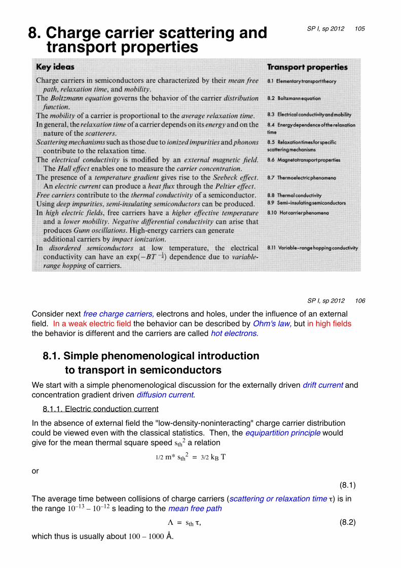
8. Charge carrier scattering andtransport properties
SP I, sp 2012 105
Consider next free charge carriers, electrons and holes, under the influence of an externalfield. In a weak electric field the behavior can be described by Ohm's law, but in high fieldsthe behavior is different and the carriers are called hot electrons.
8.1. Simple phenomenological introduction to transport in semiconductors
We start with a simple phenomenological discussion for the externally driven drift current andconcentration gradient driven diffusion current.
8.1.1. Electric conduction currentIn the absence of external field the "low-density-noninteracting" charge carrier distributioncould be viewed even with the classical statistics. Then, the equipartition principle wouldgive for the mean thermal square speed sth2 a relation
1/2 m* sth2 = 3/2 kB T
or(8.1)
The average time between collisions of charge carriers (scattering or relaxation time τ) is inthe range 10–13 – 10–12 s leading to the mean free path
Λ = sth τ, (8.2)which thus is usually about 100 – 1000 Å.
SP I, sp 2012 106

For the drift current we assume that all electrons (holes) experience the same weak externalfield E = – ∇Φ(r) of the slowly and linearly varying external potential Φ(r).By modeling "friction" due to the scattering of electrons by impurities and phonons with theabove defined relaxation time τ, the classical equation of motion of electrons becomes as
m* r̈ + (m*/τ) r· = – e E, (8.3)where the dot indicates time derivative.From the steady-state condition r̈ = 0 (and denoting more generally q = – e) we derive the driftvelocity of carriers
SP I, sp 2012 107
Define the carrier mobility µ byvd = µ E (8.10)
in the isotropic case leading toµ = qτ / m*. (8.11)
By adding the contributions of both electrons and holes we obtain for the conductivity σ = q (ne µe + nh µh). (8.14)
8.1.2. Conductivity effective mass
SP I, sp 2012 108

8.1.3. Diffusion current
8.1.4. Displacement current
SP I, sp 2012 109
8.2. Boltzmann equation and its solutionNext we consider a more general case, where the carriers are distributed according to atemperature dependent distribution function and the scattering time is charge carrier energydependent. This is also called the relaxation time approximation.The distribution function fk(T, r) gives the probability for the occupation of the band state Ek (at r) at temperature T. In the absence of the external field and thermal equilibrium this is theFermi–Dirac distribution
(8.72)
for fermions, like electrons, where µF is the chemical potential and kB is the Boltzmannconstant.In the presence of external perturbation the distribution function obeys the Boltzmannequation
(8.45)
The three terms on the right hand side include the effects from the external field, diffusion ofcharge carriers and scattering of carriers by phonons and impurities.
SP I, sp 2012 110
fk0 = 1
exp (Ek – µF)kBT
+ 1
dfkdt
= ∂fk∂t field
+ ∂fk∂t diff
+ ∂fk∂t scatt
.

Let us assume that diffusion is negligible and the applied field is weak enough that we canexpand the distribution function
fk = fk0 + gk(E),where gk(E) is the change induced by the external field E. Thus,
(8.46)
For the third term we write within the relaxation time approximation
(8.55)
which assumes the relaxation time to be k-dependent. Relaxation is due to scatteringprocesses, which we consider later. Note, that a transient perturbation gk decays away exponentially.
SP I, sp 2012 111
∂fk∂t scatt
= – gkτk
,
Now, in the steady state (e.g. in external field), from the Boltzmann equationSP I, sp 2012 112

SP I, sp 2012 113
9. Surface properties of semiconductors
Surface atomic structure
with the slab model:Pictures fromVille Arpiainen:Electronic structure andsimulated STM images ofGaAs cleavage surface(Master of ScienceThesis, TUT 2004).
SP I, sp 2012 114

9.1. Surface effects on electronic statesSP I, sp 2012 115
SP I, sp 2012 116