southern electric power distribution long term development
TRANSCRIPT

LONG TERM DEVELOPMENT STATEMENT FOR SOUTHERN ELECTRIC POWER DISTRIBUTION PLC'S
ELECTRICITY DISTRIBUTION SYSTEM
MAY 2021
Southern Electric Power Distribution is a trading name of: Scottish and Southern Energy Power Distribution Limited Registered in Scotland No. SC213459; Scottish Hydro
Electric Transmission plc Registered in Scotland No. SC213461; Scottish Hydro Electric Power Distribution plc Registered in Scotland No. SC213460; (all having their Registered Offices at Inveralmond House 200 Dunkeld Road Perth PH1 3AQ); and Southern Electric Power Distribution plc Registered in England & Wales No. 04094290
having its Registered Office at 1 Forbury Place, 43 Forbury Road, Reading, Berkshire, RG1 3JH which are members of the SSE Group www.ssen.co.uk
© Copyright: Southern Electric Power Distribution plc

Page 1 SEPD May 2021 LTDS
SOUTHERN ELECTRIC POWER DISTRIBUTION PLC LONG TERM DEVELOPMENT STATEMENT
FOREWORD Southern Electric Power Distribution plc (SEPD) is pleased to present this Long Term Development Statement (LTDS) for its electricity distribution network, both In-Area and Out-of-Area1. It is produced by Southern Electric Power Distribution plc in accordance with its Electricity Distribution Standard Licence Condition (SLC) 25. The statement covers the period 2020/21 to 2024/25. The main purpose of the LTDS is to assist our existing and prospective users in assessing opportunities available to them for making new or additional use of our distribution system. The assets referred to in this document are in the ownership of Southern Electric Power Distribution plc. They deliver electricity to about 3 million customers. Although all reasonable efforts have been made to ensure the accuracy of data, SEPD does not accept any liability for the accuracy of the information contained herein and in particular neither SEPD, nor its directors or employees, shall be under any liability for any errors. This document may not be reproduced, in whole or part, for any purpose, without the written consent of Southern Electric Power Distribution plc.
1 Out-of-Area are those SEPD owned networks not within the Southern Electric Power Distribution regional electricity company area.

Page 2 SEPD May 2021 LTDS
CONTENTS
INTRODUCTORY SECTION 3 1 PURPOSE OF STATEMENT 3 2 CONTENTS OF STATEMENT 3 3 CONTACT DETAILS 4 4 OTHER INFORMATION SOURCES 6
SUMMARY INFORMATION 8 1 GUIDING PRINCIPLES FOR PLANNING THE DISTRIBUTION SYSTEM 8 2 STANDARDS 8 3 DESIGN POLICIES 13 4 NETWORK CHARACTERISTICS 16 5 GEOGRAPHIC AND SCHEMATIC PLANS 25 6 SOURCES OF NETWORK AND CHARGING INFORMATION 25 7 NETWORK INTERFACES 26
DETAILED INFORMATION 28 8 OVERVIEW OF THE SYSTEM 28 9 NETWORK DEVELOPMENT PROPOSALS 30 10 FURTHER INFORMATION 30 APPENDIX 1 31 APPENDIX 2 33 APPENDIX 3 35

Page 3 SEPD May 2021 LTDS
INTRODUCTORY SECTION 1 PURPOSE OF STATEMENT This Long Term Development Statement (LTDS) is prepared in accordance with the direction given by the Authority (OFGEM) in compliance with paragraph 3 of SLC 25. The purpose of this statement is to:
Provide sufficient information which will assist existing and prospective new users who are contemplating entering into distribution arrangements with the licensee, to identify and evaluate opportunities.
Ensure the general availability of such information in the public domain.
Inform users of distribution network development proposals.
Provide users of the correct point of contact for specific enquiries. Users of the distribution system should also be aware that the main document which governs development and operation of the distribution system is the Distribution Code. This code covers all material technical aspects relating to connections to and the operation and use of the distribution systems of the Licensee. 2 CONTENTS OF STATEMENT 2.1 Summary Information The Summary Information section provides a brief overview of Southern Electric Power Distribution plc's distribution system in central southern England and its Out-of-Area networks, including high level information relating to the design and operation of all voltage levels of the distribution network. Small scale geographic plans providing an overview of the 132 kV and EHV networks and substations are also provided together with this document on the SSEN website. The statement contains a range of information associated with our EHV (132kV, 66kV, 33kV and 22kV) distribution system including the HV (11kV and 6.6kV) busbar of primary substations. More specific information relating to HV and LV systems is available on request. A price list for the provision of this data is included in Appendix 1. 2.2 Detailed Information
The Detailed Information section of the statement gives:
Information on the guiding principles for planning the distribution system, company internal standards, design policies and network characteristics.
Schematic and geographical plans showing the EHV system including location of EHV/EHV and EHV/HV substations.

Page 4 SEPD May 2021 LTDS
Details of embedded generation.
Planned network development proposals for which financial approvals have been given are shown in Appendix 3. They provide a summary of the work to be carried out, timescale and area of the network impacted by each proposal. These exclude like for like replacement (as this does not change system capability) and system developments for new or existing users.
Detailed information relating to:
Circuit Data, Part 2 Table 1
Transformer Data Part 2 Table 2
Demand Data Part 2 Table 3
Fault Level Data Part 2 Table 4a & 4b
Generation Part 2 Table 5
Connection Interest Part 2 Table 6 3 CONTACT DETAILS The LTDS is available free of charge by sending an email to:
or by making a request through the Southern Electric Power Distribution website:
http://www.ssen.co.uk/LTDS/ For further information relating to LTDS, or to provide feedback:
Head of Planning and Investment (South) Southern Electric Power Distribution plc
1 Forbury Place 43 Forbury Road
Reading RG1 3JH
E-mail: [email protected] Tel: 0118 9534664
Enquiries relating to new load connections or changes to existing load connections should be addressed to:
Connections and Engineering Customer Service Centre
Scottish and Southern Electricity Networks Walton Park, Walton Road
Cosham, Portsmouth PO6 1UJ
E-mail: [email protected] Tel: 0800 0483516

Page 5 SEPD May 2021 LTDS
Enquiries relating to connection of generators should be addressed to:
a. For enquiries involving greater than 50kW,
Major Connections Contracts (MCC) Scottish and Southern Electricity Networks
Perth Training Centre Ruthvenfield Way
Inveralmond Industrial Estate Perth
PH1 3AF E-mail: [email protected]
Tel: 0845 0724319
b. For enquiries involving less than 50kW,
Microgeneration Connections South
Scottish and Southern Electricity Networks Walton Park Walton Road Portsmouth PO6 1UJ
E-mail: [email protected] Tel: 03450786770
Enquiries relating to connection of generators should review the decision tree via the Southern Electric Power Distribution website or review the “My Generation” PDF for assistance: https://www.ssen.co.uk/GenerationConnectionsHome/ (The generation connection section can be found from the connection home page.) Guides are provided in this link to help you apply for your generator connection. Application forms are available through the Energy Networks Association resource library website: https://www.energynetworks.org/industry-hub/resource-library/ Alternatively, the various types of connection applications can be found here: http://www.ssen.co.uk/Offlineconnectionsapplications/.

Page 6 SEPD May 2021 LTDS
Enquiries relating to the provision of copies of the Statement of Charges for "Use of Distribution System" should be addressed to:
Distribution Pricing Team Scottish and Southern Electricity Networks
Inveralmond House 200 Dunkeld Road
Perth PH1 3AQ
Email: [email protected] Enquiries relating to the provision of copies of the “Statement of Methodology and Charges for Connection to the Distribution System" should be addressed to:
Connections Policy Team Scottish and Southern Electricity Networks
Inveralmond House 200 Dunkeld Road
Perth PH1 3AQ
Email: [email protected] The Connection and Use of System charging statements can be viewed on our website. Our Connection charging statements are revised from time to time and our Use of System charging statements are revised at least annually. Revised Use of System charges normally take effect from 1 April of each year. The latest documents can be viewed via the link below: http://www.ssen.co.uk/Library/ChargingStatements/SEPD/
4 OTHER INFORMATION SOURCES Distributed Generation Connection Guide The ENA produces connection guides to help users as an owner or developer of distributed generation to connect distributed generation to the UK’s electricity distribution networks. The guides can be viewed by searching for the guide in the ENA resource library at the link below: https://www.energynetworks.org/industry-hub/resource-library/ Guaranteed Standards All network operators have to achieve Ofgem's standards of performance for network connection services and meet strict deadlines. Ofgem recognise that not all jobs are equal, so the deadlines vary from five working days to 65 working days. If a network operator fails to meet a deadline, they have to pay compensation.

Page 7 SEPD May 2021 LTDS
The Guaranteed Standards of performance can be downloaded here: https://www.legislation.gov.uk/uksi/2015/698/made
Process to Request Additional Network Data Enquiries relating to the provision of additional network data to that contained in the LTDS should be sent to:

Page 8 SEPD May 2021 LTDS
SUMMARY INFORMATION
1 GUIDING PRINCIPLES FOR PLANNING THE DISTRIBUTION SYSTEM
The following standards are the guiding principles which underpin the policy for planning and designing the distribution network in Southern Electric Power Distribution plc:
Licence Conditions
Distribution Code
Electricity Safety, Quality and Continuity Regulations
Environmental Standards
Company Internal Standards 2 STANDARDS 2.1 Licence Conditions 2.1.1 Pursuant to a licensing scheme made by the Secretary of State, under part II of Schedule 7 to the Utilities Act 2000, Southern Electric Power Distribution plc has been granted a licence under section 6(1) (c) of the Electricity Act 1989 authorising it to distribute electricity for the purpose of giving a supply to any premises in the area specified in Schedule 1 of the Act. 2.1.2 Standard Licence Condition (SLC24) (para 1) - Distribution System Planning Standard and Quality of Supply - requires the licensee to plan and develop the distribution system in accordance with a standard not less than that set out in Engineering Recommendation (ER) P2/7. In accordance with SLC 24 (para 4) the Authority (Office of Gas and Electricity Markets - OFGEM) may, following consultation with the licensee, issue directions relieving the licensee of its obligation under para 1 (as stated in the above paragraph) in respect of the licensee's distribution system and to such extent as may be specified in the directions. In order to meet the above standard our policy is to plan networks at the most economic cost. To achieve this, we have taken two approaches:
For high volume works where point of connection is low voltage (230 and 400 V) or high voltage (11 or 6.6 kV) we have standard connection arrangements which ensure compliance with ER P2/7.
For lower volume, high cost developments, principally at EHV, i.e. 132, 66, 33 and 22 kV, we will tailor development to meet standards on an individual basis to optimise cost-benefit and customer requirements.

Page 9 SEPD May 2021 LTDS
2.1.3 Under SLC 12 - Requirement to Offer Terms for Use of System and Connection - the licensee shall, on application, offer to enter into an agreement (Connection Agreement) for use of system. Where the licensee makes an offer to enter into a connection agreement, the licensee shall, in making the offer, make detailed provision regarding:
The carrying out of the works required to connect the licensee's distribution system to any other system for distribution of electricity.
The carrying out of works in connection with the extension or reinforcement of licensee's distribution system rendered appropriate by reasons of making the connection.
The installation of appropriate meters required to enable the licensee to measure electricity being accepted into the licensee's distribution system at the specified entry point or leaving such systems at the specified exit point.
Installation of such switchgear or other apparatus (if any) as may be required for the interruption of supply where the person seeking connection or modification of an existing connection does not require the provision of top-up or standby.
The charges to be paid in respect of services required. For the purpose of determining an appropriate proportion of the costs directly or indirectly incurred the licensee shall have regard to the benefit to be obtained or likely in the future to be obtained.
In determining the costs of connection of demand and generation, the licensee shall apply the charging principles set out in the annual charging statements including, where applicable, application of:
Cost apportionment of any necessary reinforcement for the Connection; and,
Distributed Generation Incentives. The statements which set out the basis of charges for "Use of System" and "Connection to the Distribution System" are entitled:
Statement of charges for use of Southern Electric Power Distribution plc’s distribution system;
Statement of charging methodology for use of Southern Electric Power Distribution plc’s distribution system.
Statement of charging methodology for connection to Southern Electric Power Distribution plc’s distribution system.
(All the above as amended from time to time.) All the above statements are available on our website www.ssen.co.uk or by sending an email to [email protected]
Page 10 SEPD May 2021 LTDS
2.2 Distribution Code Under SLC 20 of the Licence the licensee shall prepare and at all times have in force and shall implement and comply with the Distribution Code. The Distribution Code covers all material technical aspects relating to connections to and the operation and use of the licensee's distribution system or the operation of electric lines and electrical plant connected to the licensee's distribution system. It requires the licensee's distribution system to be designed so as to permit the development, maintenance and operation of an efficient, co-ordinated and economical system and to facilitate competition in the generation and supply of electricity. The Distribution Code includes:
A distribution planning and connection code containing:
Connection conditions specifying the technical, design and operational criteria to be complied with by any person connected or seeking connection to the licensee's distribution system; and
Planning conditions specifying the technical and design criteria and procedures to be applied by the licensee in the planning and development of the licensee's distribution system and to be taken into account by persons connected or seeking connection with the licensee's distribution system in the planning and development of their own plant and system; and
A distribution operating code specifying the conditions under which the licensee shall operate the licensee's distribution system and under which persons shall operate their plant and/or distribution systems in relation to the licensee's distribution system, in so far as necessary to protect the security and quality of supply and safe operation of the licensee's distribution system under both normal and abnormal conditions.
It contains references to the following Electricity Supply Industry publications which provide guidance on planning and design criteria:
Engineering Recommendation G5/5 Planning levels for harmonic voltage distortion and the connection of non-linear equipment to transmission and distribution systems in the United Kingdom.
Engineering Recommendation G12/4 Requirements for the application of protective multiple earthing to low voltage networks.
Engineering Recommendation G99 Requirements for the Connection of generation equipment in parallel with public distribution networks on or after 27 April 2019.
Engineering Recommendation P2/7 Security of Supply.
Engineering Recommendation P14 Preferred switchgear ratings.
Engineering Recommendation P24 AC traction supplies to British Rail.

Page 11 SEPD May 2021 LTDS
Engineering Recommendation P25
The short circuit characteristics of electricity boards low voltage distribution networks and the co-ordination of overcurrent protective devices on 230V single phase supplies up to 100A.
Engineering Recommendation P26/1 The estimation of the maximum prospective short circuit current for three phase 415V supplies.
Engineering Recommendation P28 Planning limits for voltage fluctuations caused by industrial, commercial and domestic equipment in the United Kingdom.
Engineering Recommendation P29 Planning limits for voltage unbalance in the United Kingdom for 132kV and below.
Technical Specification 41-24 November 2009 Guidance for the design, installation, testing and maintenance of main earthing systems in substations.
Engineering Recommendation S34 A guide for assessing the rise of earth potential at substation sites.
Engineering Recommendation G98 Requirements for the connection of Fully Type Tested Micro-generators (up to and including 16 A per phase) in parallel with public Low Voltage Distribution Networks on or after 27 April 2019 Engineering Recommendation G81 Framework for design and planning, materials specification and installation and record for Greenfield low voltage housing estate installations and associated, new, HV/LV distribution substations. (Related SEPD specifications are detailed on our website.) https://www.ssen.co.uk/connections/usefuldocuments/ DTI Publication - Technical Guide to Connection of Embedded Generators to the Distribution Network (KEL 000318).
See Section 7 for enquiries relating to the Distribution Code. 2.3 Electricity Safety, Quality and Continuity Regulations The Secretary of State issued The Electricity Safety, Quality and Continuity Regulations in 2002 in order to:
Ensure that the electricity supplies are regular and efficient.
Protect the public from dangers arising from distribution of electricity, use of electricity supplied or from installation, maintenance or use of any electricity line or electrical plant.
Eliminate or reduce the risks of personal injury or damage to property or interference with its use.
Regulation 27 gives permitted variations at all low voltage customers' terminals of +10% and -6% of the declared voltage of 230 V single phase or 400 V three phase. For higher voltages below 132 kV the permitted variations are between +6% and -6%
Page 12 SEPD May 2021 LTDS
of the declared voltage, and at 132 kV or above they are between +10% and -10% of the declared voltage. It is therefore necessary to hold the system voltage within these ranges on all systems to which customers are connected, i.e. all low voltage systems, most HV systems and some EHV systems. 2.4 Environmental Standards Schedule 9 of the Electricity Act 1989 requires SEPD to consider the effect of its work on the amenity and fisheries and to mitigate the effects where reasonable. In planning, designing and operating the distribution system our policy is to pay due regard to environmental matters and, in particular, noise, visual amenity and pollution. We seek Planning Authority and Department of Trade and Industry approval to build new lines. We also endeavour to meet the requirements of other bodies, such as Natural England and the Environmental Agency, in protected areas such as Areas of Outstanding Natural Beauty. We will seek to avoid disturbance or detriment to such areas as far as reasonably practicable consistent with the economic and reliability impact on our distribution network and on customers' costs. 2.5 Company Internal Standards In addition to meeting the above standards, SEPD has internal standards to improve quality of supply and reduce duration of supply interruptions. 2.5.1 General The targets for duration of supply interruption, customer minutes lost (CMLs) per customer per year, and number of customer interruptions (CIs) are agreed with OFGEM. These standards are in addition to the Guaranteed Standards set by OFGEM. In planning, designing and operating the distribution system the systematic use of automation, mobile generation and targeted investment for refurbishment of the distribution system is designed to deliver these targets. To meet the individual needs of customers, we will agree standards of connection whether in excess or lower than the appropriate levels as stated in the relevant network standard. In these cases, we will agree special commercial terms. 2.5.2 Capacity Planning To ensure that the distribution system has adequate capacity to meet system demand, voltage and current flows are regularly monitored and adequacy of the network is checked. Capacity is benchmarked to estimated loads. Where there is a shortfall in network capacity we will seek appropriate solutions. These will usually involve network reinforcement but could involve alternative solutions. 2.5.3 System Voltage Control
Page 13 SEPD May 2021 LTDS
The total full load volt drop for the transfer of power from the high voltage distribution system to the low voltage supply system is approximately 30%. Therefore, voltage correction must be applied in the appropriate places to comply with Regulation 27 of the Electricity Safety, Quality and Continuity Regulations 2002. This is carried out as follows:
In higher voltage system by:
Control of reactive power flows. This includes switching in or out lightly loaded circuits, shunt capacitors and reactors, use of synchronous compensators, operation of "tap-stagger" and use of voltage above or below nominal.
Auto/manually controlled on-load tap changers on 400/132kV and 275/132 kV transformers).
Central control by despatch of reactive power from synchronous generators.
Automatic voltage control on synchronous generators.
In the lower voltage systems by:
Automatically controlled on-load tap changers fitted to 132/33 kV and 33/11 kV transformers;
Line drop compensation on most 11 kV systems;
Reactive compensation (shunt reactors and capacitors);
Off load tap changers fitted to 33 kV/LV and 11 kV/LV transformers;
Voltage regulators on the LV system. 3 DESIGN POLICIES 3.1 General When planning and designing an electricity distribution system it is necessary to consider all alternative options to achieve an optimum solution based on technical and economical considerations. The Company's distribution system has been standardised at 132 kV, 66 kV, 33 kV and 22 kV (called EHV), 11 kV and 6.6 kV (called HV) and 230/400 V (called LV). Demand forecast methodology is formulated around a combination of important contributing factors impacting demand. Historic growth rates for each primary substation are calculated before being banded into four growth trends of Zero, Low, Medium or High. Individual future growth rates are based on the calculated historic trend and key drivers including committed connections, geographic economic factors derived from local authority development plans and demand forecast from large users with knowledge of major changes in connected load. The key assumptions included in the demand forecast are as follows:
The average cold spell (ACS) forecast assumed system peak demand is adjusted so the annual forecast references to a common temperature base. A

Page 14 SEPD May 2021 LTDS
weighted average temperature, where ambient temperature is considered over a three-day period, is used in the calculation and appropriate adjustments are made to demand readings to produce the ACS values, which is what the demand would have been if the ambient temperature had been 0° C.
The forecast includes contributions (power export) from embedded distributed generators (DG) running at the time of system peak. The projection includes an annual average of 8% contribution from DG.
Consistent running arrangement and system configurations are considered. Recorded substation peak demands are normalised to account for abnormal running arrangement to ensure the forecast is consistent with previous years running arrangement.
Individual demand forecast submissions from large consumers are factored into forecasts.
Committed new loads and new connections are assumed to materialise in the manner predicted i.e. user timing and usage is assumed to occur as advised/requested by customer.
SEPD will undertake further assessments to determine whether intervention is required where the calculated planning fault levels, identified in Table 4, exceed 95% of the circuit breaker fault level rating. The additional assessments undertaken by SEPD include, but are not limited to, site specific protection settings analysis and circuit breaker trip testing. If further assessments confirm that intervention is required SEPD will determine the most economic, efficient and cost-effective solution to reduce the overall fault level. Possible mitigation works include, but are not limited to, opening the bus-section circuit breaker, reconfiguring the network, installing fast response automation and extending circuit breaker trip times. Fault level information is published for planning purposes only. It should not be used for operational purposes and does not necessarily reflect current operational circumstances. 3.2 132 and 33 kV System Design 132 kV and 33 kV networks from 400/132 kV and 132/33 kV substations (or equivalent 66 kV and 22 kV networks) normally run either radially or as open or closed rings. However, some networks run in parallel with those from other sources where technically acceptable and economically advantageous. Additions to or reinforcements of these networks are considered individually and tailored to the existing network arrangements. The most economic investment is determined in line with any long-term proposals and having regard to network complexity, operational requirements and flexibility. Studies are completed to ensure acceptable voltage conditions, compliance with security of supply standards for first and second circuit outages in accordance with

Page 15 SEPD May 2021 LTDS
Engineering Recommendation P2/7 and that circuit and plant ratings are not exceeded. Additionally, for generation, studies are completed to identify any locations where increased fault currents exceed switchgear ratings. For larger sets, or where there is likely to be interaction with existing customers with large motor drives, steady state and transient stability studies are needed to:
Ensure generation and the networks remain stable following circuit switching or a network fault.
Check interaction with other nearby generation.
Predict any possible loss of synchronism and the corresponding need for additional protection to avoid damage to the generator or unacceptable voltage or power swings.
3.3 Supplies from Primary (typically 33/11 kV) Substation The maximum number of 11 kV circuits from a 33/11 kV substation is determined on the basis of network configuration and maximum utilisation, e.g. for a substation with 2 x 15/30 MVA transformer capacity, the normal maximum number of 11 kV feeders would be 8. Interconnecting feeders, where practical, would emanate from separate sections of busbar consistent with minimising initial switchgear requirements and allowing for future extensions. New feeders will be controlled by automatic circuit breakers of 630 A nominal load rating. 3.4 HV Network Configurations The HV network is normally configured to achieve maximum utilisation whilst maintaining security of supply standards at a minimum cost. The HV urban network is normally configured as a "loop-tee-loop" arrangement in an open "ring" formation. However, where an individual customer requires more or less security of supply standard, then the connection to that customer will be designed to meet specific needs. The HV rural network is normally configured as an open "ring" with pole mounted HV/LV transformers directly connected. However, where group demand is below 1 MVA the network configuration may be radial feed with no backfeed facility. Furthermore, there may be lengthy spurs (single and three phase), in particularly remote locations, served by overhead line circuits. 3.5 Low Voltage Network Configuration The feeding arrangement on the low voltage network is normally radial with no interconnection. There is existing interconnected LV network which operates as radial

Page 16 SEPD May 2021 LTDS
and is configured as an "open" ring. The layout of distributors is optimised in relation to services to be supplied. Distributors are normally laid in footways.
4 NETWORK CHARACTERISTICS 4.1 Standard Plant and Equipment sizes Various types of plant and equipment exist on the EHV and HV systems. Typical details are given below. 4.1.1 132 and 66 kV System
Bulk Supply Point Transformers
Voltage Ratio 132/33 kV Vector Group YD1, YD11 Rating 90, 60, 45, 30 MVA Tapping Range -10% to +20% and -10% to +10% (on load)
Voltage Ratio 132/22 kV Vector Group YD1 Rating 60, 45 MVA Tapping Range -10% to +20% and -10% to +10% (on load)
Voltage Ratio 132/11 kV Vector Group YD1, YD11, YY1, YY11 Rating 45, 30, 20, 15 MVA Tapping Range -10% to +20% and -10% to +10% (on load)
Voltage Ratio 66/22 and 66/11 kV Vector Group YY6 Rating 60, 40, 30, 20 MVA Tapping Range -10% to +20% and -5% to +15% (on load)
Switchgear
132 kV CBs Current Rating 800, 1200, 2000, 3150 Amps Fault rating 18.4, 25, 31.5, 40 kA
66 kV CBs Current Rating 800, 1200, 2000, 3150 Amps Fault rating 21.9, 25.0, 40 kA
4.1.2 33 and 22 kV System
Primary Transformers
Voltage Ratio 33/11 and 33/6.6 kV Vector Group DY1, YY0, DY11 Rating 3, 5, 7.5, 7.5/15, 10, 15, 12/24,15/30, 20/40 MVA Tapping Range -5% to +15%, -10% to +10% (on load)
Voltage Ratio 22/11 and 22/6.6 kV Vector Group DY1

Page 17 SEPD May 2021 LTDS
Rating 5, 10, 12.5, 14 MVA Tapping Range -5% to +15%, -10% to +10% (on load)
Voltage Ratio 33 kV/LV (433 V) Rating 300 kVA and less Tapping Range -5% to +5% (off load)
Switchgear
33 kV Circuit Breakers Current Rating 400, 800, 1200, 2000, 2200 Amps Fault rating 13.1, 17.5, 20, 25 kA
22 kV Circuit Breakers Current Rating 400, 800, 1200, 2000 Amps Fault rating 13.1, 17.5, 25 kA
4.1.3 11 & 6.6 kV System
Distribution Transformers Vector Group DY11 Voltage Ratio 11 or 6.6 kV/LV (433 V, 500 V or 250 V) Rating 1000, 500, 315, 200 kVA and less Tapping Range -5% to +5% (off load)
Switchgear (11kV and below) Current Rating: 400, 630, 800, 1250 A Fault rating: 250 MVA or 350 MVA - some pole mounted switchgear may be rated below 250 MVA.
4.1.4 Telecontrol Normally all 22 kV or higher voltage switchgear is equipped with telecontrol. Use of telecontrol at 11 kV is considered according to the situation and location. 4.1.5 Batteries SEPD will normally provide its own battery systems for substation protection and control equipment where needed. However, shared use is considered if appropriate. 4.2 Power Quality 4.2.1 Harmonics Engineering Recommendation G5/5 sets the planning levels for harmonic voltage distortion to be used for the connection of non-linear equipment. These levels should not normally be exceeded when considering the connection of non-linear loads and generating plant to the distribution networks under the Distribution Code. The table below gives a summary of Total Harmonic Distortion (THD) planning levels:
System Voltage at point of common coupling
THD Limit
LV ( 400 V) 5% HV (< 20 kV) 4% EHV (< 400 kV) 3%
The assessment procedure for non-linear equipment uses three stages:

Page 18 SEPD May 2021 LTDS
Stage 1 – connection of equipment of limited size to LV networks without individual assessment.
Stage 2 – connection of larger equipment than the maximum in Stage 1 to all systems less than 33 kV. Measurements may be necessary. Predicted levels need to be less than specified levels.
Stage 3 – connection at 33 kV and above or loads not acceptable under Stage 2. Measurement of existing harmonic distortion will be necessary.
The objective is to balance the degree of detail with degree of risk that the connection of the particular equipment will result on the supply system. 4.2.2 Voltage Fluctuations Engineering Recommendation P28 sets the planning limits of voltage fluctuations caused by industrial, commercial and domestic equipment. Allowable limits vary with the interval between fluctuations and are based on the likelihood of customer complaints. Normally acceptable values are 3 % and below. 4.2.3 Unbalance Engineering Recommendation P29 sets the limits of voltage unbalance on networks up to 132 kV. Normally acceptable values are 2 % and below. 4.2.4 Investigations There are no areas in SEPD where harmonic levels, voltage fluctuations or unbalance are known to be an issue. However, we will investigate and take measurements in response to customer requests. If the harmonic level is found to be unacceptable, we will seek an appropriate solution. 4.3 Method of Earthing 4.3.1 132 kV systems These systems normally use multiple direct neutral point earthing. 4.3.2 High Voltage System The methods currently employed to earth the neutral of High Voltage networks at EHV/EHV and EHV/HV substations are:
Direct Earthing
The only impedance between the transformer lower voltage winding star point (neutral) and earth consists of the earthing conductor and the resistance between the earth mat and earth.
Resistance Earthing
Use is made of an earthing resistor between the transformer lower voltage winding star point (neutral) and earth to limit the earth fault current.
Earthing Transformers
In instances where the transformer lower voltage winding is delta connected a neutral point is derived artificially by inclusion of an earthing transformer. This neutral point is then appropriately earthed.

Page 19 SEPD May 2021 LTDS
4.3.3 Distribution Substations Earthing is provided for HV metal work, LV neutral and extraneous metal work not associated with the power system e.g. fences etc. Where the overall resistance to earth does not exceed 1 ohm the HV metal work, LV neutral earth and fence metal work (within 2 metres of HV metal work) are combined together. Where the overall resistance to earth exceeds 1 ohm HV metal work earth, LV neutral and fence metal work earths are kept separate and resistance to earth of each separate earth electrode must not exceed 40 ohms. 4.3.4 Low Voltage System The method applied to earth the LV system of most new networks and many existing networks is Protective Multiple Earthing (PME). This refers to the use of the supply neutral conductor of the LV network to provide earthing facilities for customers. There is also use of Continuous Earth Wire, Separate Neutral and Earth and Protective Neutral Bonding systems. The general requirements that must be fulfilled are:
The supply neutral conductor will be connected to an earth electrode at or near the transformer star point.
The supply neutral conductor will not contain a fusible cutout, circuit breaker or switch.
The value of the transformer neutral earth electrode will not exceed 40 ohms.
The overall resistance to earth of the supply neutral conductor will not exceed 20 ohms.
In addition to the neutral earth at or near the transformer star point, the supply neutral conductor will be connected to other points either to earth electrodes or supply neutral conductor of another distributing main. 4.4 Protection Systems 4.4.1 General Protection equipment is used to recognise, locate and initiate removal of a fault or abnormal condition from the power system, normally by operation of a switching device. Circuit breakers and relays are normally used at higher voltages, but fuses are employed where relays are not economically justified. To avoid unnecessary damage to plant and equipment and to minimise disconnection of healthy plant, it is essential that the protection systems employed on the distribution system are reliable, selective, fast and sensitive. 4.4.2 LV Feeders In most cases low voltage feeders are protected by fuses. These provide short circuit protection to the main feeder and connected services. The fuses are rated to provide discrimination with HV protection. 4.4.3 11 kV/LV Transformers (Ground Mounted)
Page 20 SEPD May 2021 LTDS
Ground mounted 11 kV / LV transformers are normally protected by HV fuse switches. The fuses provide protection for faults on the HV cable to the transformer, faults within the transformer and faults on the LV connections. 4.4.4 11 kV/LV Transformers (Pole Mounted) Pole mounted 11 kV / LV transformers receive protection from either feeder circuit breaker, pole mounted auto reclosers / sectionalisers or pole mounted HV fuses. 4.4.5 11 kV Feeders 11 kV feeders are normally protected by circuit breakers with the following protections and typical clearance times:
Predominantly underground circuits:
IDMT overcurrent and earth fault protection - up to 1 s, but possibly up to 3 s depending on fault type and location.
Predominantly overhead line circuits:
Instantaneous high set overcurrent - 150 ms.
Time delayed overcurrent and earth fault - 400 ms.
IDMT overcurrent and earth fault - 50 ms – 3 s
Time delayed sensitive earth fault - 7 s.
Auto-reclosing as para. 4.6 Additional pole mounted auto reclosers are strategically located on the overhead network to limit the number of supply interruptions to customers for transient and permanent faults. 4.4.6 33/11 kV Transformers 33/11 kV transformers typically have the following protection and clearance times:
High set overcurrent, instantaneous earth fault and restricted earth fault – 150 ms.
3 stage standby earth fault - 1.4 s, 2.1 s and 2.9 s.
IDMT overcurrent and earth fault - up to 3 s.
Neutral voltage displacement protection - 3 – 10 s.
Buchholz and winding / oil temperature relays.
Intertripping or fault throwing switch if needed to trip remote circuit breaker – 300 ms or operating time of remote protection.
4.4.7 33 kV Feeders and Transformer Feeders 33 kV feeders are normally protected by circuit breakers fitted with protection dependent upon feeder type (overhead or underground cable). Typical protection provided (and clearance time) is a selection from:
Unit protection - 150 ms.
Distance protection - 150 ms zone 1, 500 ms zone 2, 1.3 s zone 3.
IDMT overcurrent and earth fault - up to 3s.

Page 21 SEPD May 2021 LTDS
Auto-reclosing as para. 4.6 for predominately overhead circuits. Additional protection is needed if remote transformers are connected, typically:
High set overcurrent - 150 ms.
Instantaneous earth fault - 150 ms.
Intertripping over pilot cable or fault throwing switch. 4.4.8 132/33 kV Transformers 132/33 kV transformers typically have the following protection and clearance times:
Overall biased differential, high set overcurrent, instantaneous earth fault and restricted earth fault protections - 150 ms.
3 stage standby earth fault protection - up to several seconds.
Buchholz and winding / oil temperature relays.
Intertripping or fault throwing switch if needed to trip remote circuit breaker - 300 ms.
4.4.9 132 and 66 kV Busbars 132 and 66 kV busbars are normally protected by busbar protection to provide discrimination and to isolate the faulted section of busbar. Typical clearance time is 150 ms. 4.4.10 132 and 66 kV Feeders and Transformer Feeders 132 and 66 kV feeders are normally protected by circuit breakers fitted with protection dependent upon feeder type (overhead or underground cable). Typical protection provided and clearance times are:
A single main protection, either unit protection - 150 ms, or distance protection - 150 ms zone 1 or 500 ms zone 2. Additionally, if a transformer is remotely connected:
High set overcurrent - 150 ms.
High set earth fault - 150 ms.
Intertripping may be installed.
Back up protection to cater for failure of the main protection, normally IDMT overcurrent and earth fault - 1.1 s and 1.2 s, or distance protection zone 3 - 0.9 s.
Auto-reclosing as para. 4.6 for predominately overhead circuits. 4.5 Network Automation In order to minimise customer minutes lost and customer interruptions due to outages, where economically viable, opportunity is taken to automate the HV distribution system by installing in-line circuit breakers or actuators. 4.6 Auto Reclosers The majority of faults on overhead lines are of transient nature (e.g. insulator flash over) generally caused by wind borne materials. These faults are normally cleared by opening of the source circuit breaker or pole mounted recloser and do not recur when reclosed. Auto-reclosing is therefore applied to most predominantly overhead circuits.

Page 22 SEPD May 2021 LTDS
Typical or preferred settings, where relays permit, are:
11 kV source circuit breaker:
Trip 1 - Instantaneous high set overcurrent or time delayed overcurrent or earth fault or sensitive earth fault.
10 s dead time.
Trip 2 - IDMT overcurrent or earth fault or time delayed sensitive earth fault.
90 - 120 s dead time (or lock-out if sensitive earth fault).
Trip 3 - IDMT overcurrent or earth fault to lock-out.
Reclaim time 5 s.
11 kV pole-mounted circuit breakers:
Settings to co-ordinate with the above.
Final dead time 90 or 120 s.
33 kV circuit:
Single shot.
90 s dead time.
5 s reclaim time.
132 kV circuit
Single shot.
15 s dead time.
5 s reclaim time. 4.7 Operating Voltages The company's distribution system operates at nominal voltages such as 132, 66, 33, 22, 11, 6.6 kV and 230/400 V. 4.7.1 General Voltage control is applied at various voltage levels to ensure that statutory levels are maintained at customers' supply terminals as below. 4.7.2 Voltage Control of HV (11 and 6.6 kV) and LV system Automatic control of the 11 kV source voltage is obtained by the on-load tapchanger on the 132/11, 66/11 and 33/11 kV transformers. The interval between taps is typically 1.25% or 1.43%. Line drop compensation is normally applied to rural 33/11 kV transformer tapchanger control schemes to arrange an automatic increase in the 11 kV source voltage with increase in demand. Typical settings are 1.05 p.u. at full load and 0.985 p.u. at no load. The 11 kV system is typically designed to accommodate 6% volt drop. The low voltage system is typically designed so that the aggregate volt drop in the low voltage distributor and service does not exceed 7% with normally less than 2% in the service.

Page 23 SEPD May 2021 LTDS
4.7.3 Voltage Control of EHV (33 and 22 kV) System The voltage at the 33 kV source is set to the highest permissible value, typically 1.03 p.u., in order to permit maximum design volt drop in the 33 kV system. It is also chosen to ensure that the required 11 kV and LV busbar voltages at both nearby and remote substations can be achieved. 4.7.4 Voltage Control of 132 kV System The 132 kV voltage at a 400/132 kV Grid Supply Point is maintained by National Grid plc at a mutually agreed level and is usually between 1.00 and 1.05 p.u. Each part of the system is studied in detail taking in to account normal and abnormal conditions, circuit configuration, tap ranges, impedances, demand and voltage required at the 33 kV busbars. 4.8 Generation Connection Policy The principal duty placed on the Authority is to protect the interest of consumers having regard to the need to secure that all reasonable demands for electricity are met. This duty is devolved to the licensee to develop the distribution systems in an economical manner whilst maintaining defined planning standards. The implications are that whereas demand for electricity must be met year-round, generators will not always be able to simultaneously generate at their authorised capacity since the supply and demand for electricity must be balanced at all times. Therefore, it is necessary that, before any offer for connection is made, detailed network analysis is carried out to ascertain the impact of generation so that the quality of supply to connected consumers is not compromised. Generators connected to the LV, HV or EHV distribution system must comply with the general principles specified in Engineering Recommendation G99 and associated Engineering Technical Report no.113 or G98 as applicable. Where appropriate, the requirements of the Distribution Code and Grid Code must be met. It is a requirement that Neutral Voltage Displacement will be fitted to all generators where the size of the generator or group of generators on the same connection point exceeds 200kVA. This is to ensure that the risks of back-energising the 11kV network from an LV generator is small. 4.9 Load Management Areas In compliance with the Grid Code and on receipt of instructions from NGC, voltage reduction may be applied to reduce demand and maintain system frequency. There are no load management areas in SEPD. 4.10 Network Constraints and Opportunities There are constraint areas for accepting new generation or load. However, background fault levels at most voltages are generally high. This is due to a higher fault infeed from the 400 kV transmission system and the lower impedance of the distribution system. There is currently about 3380 MW of embedded generation connected to the distribution system at various voltages across the whole area served by SEPD.
Page 24 SEPD May 2021 LTDS
Approximately 500 MW is concentrated around the areas supplied by Fawley and Nursling 400/132kV substations. The continued growth in generation connecting at distribution voltages is driving ongoing improvements in how SEPD seeks to provide information and assistance to customers wishing to connect to its network. The current trend of growth in generation connections has reinforced the importance of SEPD continuing to develop and recognise its responsibility to provide information and assistance. This is coupled with the ongoing need for strong customer interaction and support to potential distributed generation customers. It is essential that prospective generation developers work with SEPD to ensure correctly located and well-matched generation is incorporated into its network to the mutual benefit of both customers and SEPD. Key areas that need to be discussed and monitored are the impacts of the generation on the network and the impacts of the network on the generation. The addition of generation to the network impacts the system fault levels, which in turn can lead to network reinforcement works being necessary to support the connection. The power flows experienced by the modified network, if not accurately analysed, monitored and controlled, could cause system overload, over and under voltage, system frequency variations and reduce system power factors. All of these are undesirable on the distribution network. All are points that must be considered when designing and developing a generation connection. Networks may well have to be redesigned in order to best adapt to the generation connection requirement. This will add both cost and time to the connection project and should be considered and remembered when submitting any such connection enquiry or request. There are benefits to the network. Connection of well sited and adaptable generation could provide network support and reduce network losses. The development must supplement SEPD’s responsibility to deliver a safe, secure and reliable network and be in keeping with our ethos to “deliver energy in a safe and sustainable way”. When considering connecting new load or generation to the network, it must be thoroughly planned and designed to meet the requirements set out in the Distribution Code, and in line with the information contained within this LTDS document. Depending upon connection size and type, an application may need to be made to National Grid for a “Statement of Works” OR “Modification Application”. This can be discussed at the point of request for information or during the initial scoping of any connection enquiry. There may be charges associated with these applications. The following short guide may assist users who wish to complete initial investigations and assessments of proposed connections to SEPD’s network. Key Milestones in the investigation process.
Page 25 SEPD May 2021 LTDS
Fill out a generation connection form, available from the ENA Resource Library website and submit this to SSEN: https://www.energynetworks.org/industry-hub/resource-library/
This will commence dialog with the company in relation to the connection request.
Identify your new Connection, Generation or Load. State the capacity and type of generation to connect; Wind, Solar, Hydro, combined Heat and
Power systems, Bio-mass or other. Unless a specific location is required, select an area on the LTDS geographic map or select a
substation local to the desired connection area. Using the information available in the LTDS investigate that the selected substation’s capacity,
demand, forecast demand and fault level could support the new connection. Collect technical data from LTDS and perform self study
o Carry out study of the impact of new generation on the existing network parameters including;
o Fault level contribution of connecting new generator
o Clean or dirty load giving rise to System harmonics
o Impedance of the unit, how will this alter fault level?
o What is the effect under 1st circuit outage conditions?
Connection charges will vary with the location and size of the proposed connection. At the point of connection request or enquiry, costings will be advised in line with the Southern Electric Power Distribution Statement of Methodology and Charges for Connection to Southern Electric Power Distribution’ Electricity Distribution System. http://www.ssen.co.uk/Library/ChargingStatements/SEPD/
Applications for connection of generation are evaluated on an individual basis. Information on generation connections and applications can be found in Table 5 and Table 6 of this statement’s data section which summarises larger embedded generation installations in SEPD’s area. 5 GEOGRAPHIC AND SCHEMATIC PLANS The following are shown separately on maps provided with the main LTDS document:
Schematic plans for the EHV system showing the electrical connectivity of the system.
Geographic maps showing routes of EHV circuits and the location of EHV/EHV and EHV/HV substations.
Maps of larger scale for EHV, HV and LV systems for a particular area are available on request. A price list for these is included in Appendix 1. 6 SOURCES OF NETWORK AND CHARGING INFORMATION As described in Summary Information Section 2.1.3, the statements which set out the basis of the "Use of System" and "Connection to the Distribution System" charges are as follows:

Page 26 SEPD May 2021 LTDS
Statement of charges for use of Southern Electric Power Distribution plc’s distribution system;
Statement of charging methodology for use of Southern Electric Power Distribution plc’s distribution system.
Statement of charging methodology for connection to Southern Electric Power Distribution plc’s distribution system.
All the above statements are available on the SSEN website at www.ssen.co.uk or by sending an email to [email protected] 7 NETWORK INTERFACES The Distribution Code (http://www.dcode.org.uk/) specifies the process for managing network development at interface point with users, which includes other Network Operators. It also describes the interface with the National Electricity Transmission System. SEPD's distribution system above 11 kV interconnects with:
The transmission system of National Grid plc at the following locations:
Acton Lane 66/22 kV substation (this also supplies UK Power Networks plc (UKPN) distribution system),
Amersham 400/132 kV substation (this also supplies UKPN’s system),
Axminster 400/132 kV substation (this also supplies WPD's system),
Botley Wood 400/132 kV substation,
Bramley 400/132 kV substation,
Chickerell 400/132 kV substation,
Cowley 400/132 kV substation,
Ealing 275/66 kV substation,
Fawley 400/132 kV substation,
Fleet 400/132 kV substation,
Iver 275/132/66 kV substation,
Laleham 275/132 kV substation (this also supplies UKPN’s distribution system),
Lovedean 400/132 kV substation,
Mannington 400/132 kV substation,
Melksham 400/132 kV substation,
Minety 400/132 kV substation,
North Hyde 275/66 kV substation,
Nursling 400/132 kV substation,
Willesden 275/66 kV substation (this also supplies UKPN’s distribution system),
Tynemouth 275/11kV substation.

Page 27 SEPD May 2021 LTDS
Western Power Distribution (South West)'s distribution system at:
Yeovil 132/33 kV substation,
Winterborne Abbas 33 kV substation,
Melksham 132 kV substation.
Contact details for these companies are:
UK Power Networks
Fore Hamlet Ipswich IP3 8AA
National Grid plc
NGT House Warwick Technology Park
Gallows Hill Warwick
CV34 6DA
Western Power Distribution (South West) plc Avonbank
Feeder Road Bristol
BS2 0TB
Page 28 SEPD May 2021 LTDS
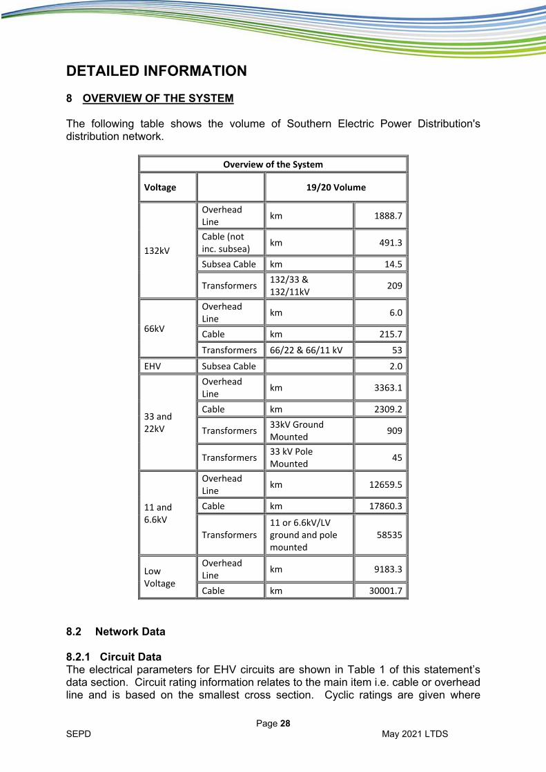
DETAILED INFORMATION 8 OVERVIEW OF THE SYSTEM The following table shows the volume of Southern Electric Power Distribution's distribution network.
Overview of the System
Voltage 19/20 Volume
132kV
Overhead Line
km 1888.7
Cable (not inc. subsea)
km 491.3
Subsea Cable km 14.5
Transformers 132/33 & 132/11kV
209
66kV
Overhead Line
km 6.0
Cable km 215.7
Transformers 66/22 & 66/11 kV 53
EHV Subsea Cable 2.0
33 and 22kV
Overhead Line
km 3363.1
Cable km 2309.2
Transformers 33kV Ground Mounted
909
Transformers 33 kV Pole Mounted
45
11 and 6.6kV
Overhead Line
km 12659.5
Cable km 17860.3
Transformers 11 or 6.6kV/LV ground and pole mounted
58535
Low Voltage
Overhead Line
km 9183.3
Cable km 30001.7
8.2 Network Data 8.2.1 Circuit Data The electrical parameters for EHV circuits are shown in Table 1 of this statement’s data section. Circuit rating information relates to the main item i.e. cable or overhead line and is based on the smallest cross section. Cyclic ratings are given where
Page 29 SEPD May 2021 LTDS
appropriate. In practice other items such as current transformers, protection equipment and isolators may restrict the circuit rating. The information is intended to illustrate the basic circuit capability. The vast majority of circuits operate at their construction voltage. 8.2.2 Transformer Data EHV/EHV and EHV/HV transformer data is shown in Table 2. A site-specific analysis can be carried out to ascertain the reverse power capability of each transformer. 8.2.3 Demand Data The maximum demand recorded at the substation during the previous twelve months is shown in MVA and power factor in Table 3. The forecast demand is normally based on the historical growth trend plus any large known development. Firm capacity for multiple transformer sites relates to the remaining capacity under n-1 (largest unit loss), although higher loads can often be supplied by using load transfers or mobile or local generation. Note that limitations in the higher voltage network may restrict spare capacity. For single transformer sites the demand will normally be secured by use of interconnection, mobile generation or combination of both. The minimum load scaling factor is the ratio of minimum to maximum demand. Appendix 2 shows typical substation load profiles. 8.2.4 Fault Level Data Calculated three phase fault level (plus single phase fault levels for 132 kV) data under normal running arrangements is shown in Table 4A (132 kV) and Table 4B (6.6, 11, 22, 33 and 66 kV). Normally there will be more than one circuit breaker at a substation site; the make and break ratings shown relate to the existing circuit breakers. At most sites, not all circuit breakers would be subject to the fault currents given. Fault currents given include contributions from all transmission and distribution networks and generation included in our study model. The break current will be dependent on the break time. Break current values given in this statement are decremented RMS values at 50 ms. This decay time is a conservative assumption and may vary for some sites. Make values include contributions from induction motors as per Engineering Recommendation G74. Normally break and make fault currents will not be allowed to exceed switchgear ratings. 8.2.5 Connected Generation Table 5 details the substation and connection voltage of various types of generation connected to the network. All listed units are greater than 1 MW generation capacity. 8.2.6 Interest in a connection Table 6 details the recent interest in connection of various load and generation connections by substation. The table presents the number of formal and budget enquiries, the number of accepted applications and the total cumulative capacity of all applications. 8.2.7 Busbar and node codes

Page 30 SEPD May 2021 LTDS
Table 7 details the busbar and node codes used in the Tables. There are also diagrams that show how the various busbars interconnect. These can be found separately on the Long Term Development Statement webpage. 8.3 Other Information Additional information is available on request:
Circuits e.g. zero sequence impedance.
Transformers e.g. earthing details, hot sites.
Demand e.g. limitation on firm capacity, demand duration profiles.
Fault Level e.g. contributions to fault current at each node, decremented break fault currents, details of limitations and indicative cost to relieve.
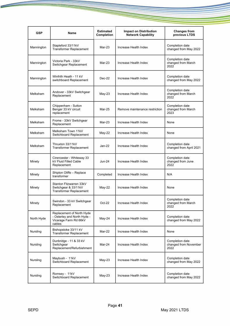
A price list for provision of such additional information is included in Appendix 1; contact details are in Part 1 Section 3. 9 NETWORK DEVELOPMENT PROPOSALS Appendix 3 lists financially approved distribution system reinforcement proposals. These schemes are either under construction or are in the design stage. 10 FURTHER INFORMATION 10.1 Distribution Code
See: www.dcode.org.uk 10.2 Electricity Ten Year Statement
See: http://www.nationalgrid.com/uk 10.3 Engineering Recommendations Copies of National Engineering Recommendations and Technical Specifications are available from:
Energy Networks Association 6th Floor
Dean Bradley House 52 Horseferry Road
London SW1P 2AF
Tel: 020 7706 5100
Email: [email protected]
or
www.energynetworks.org

Page 31 SEPD May 2021 LTDS
APPENDIX 1
NETWORK INFORMATION PRICE LIST SEPD will be able to provide additional and/or site-specific network information on request. The price list given below is for general data which is normally available but will require time and effort to collect. The person making the request should define the specific areas of interest including details of the substation group and the substation or busbar node names. For some site-specific enquiries and for those items which are not included in the list below, it may be necessary to carry out network analysis, site checks and in some cases shut down of the network to obtain information. A quotation will be provided to the customer before work is undertaken. Network Data a) Reliability Data Typical reliability data for EHV, HV and LV system £25 per voltage Specific circuit reliability data £100 per circuit b) Demand Data Specific demand (maximum and minimum) data - normal £100 per circuit running for EHV and HV circuits c) Impedance Data Specific 11 kV circuit impedance data £50 per circuit Specific EHV circuit data additional to LTDS standard data £50 per circuit d) Plant Data Rating, fault levels rating and protection details without site £100 per site visit. (Where site visit is required, price will be provided on request) Any request for the above information should be sent in writing (see Part 1 Section 3 for contact details) accompanied with a cheque payable to Southern Electric Power Distribution plc. Under normal situations return of information will be within 15 working days. Geographic Mapping Information Maps and network plans are available on request from our Mapping Services department. One set of specific EHV system map with OS background £50 per set One set of specific EHV schematic diagrams £50 per set One set of specific HV system map with OS background £50 per set One set of specific HV schematic diagrams Price on request One set of specific LV schematic diagrams Price on request “One set of specific system mapping” Is defined as a 2km area centred as requested by the customer. This can be produced in either paper format or as a digital shape file or PDF.
Page 32 SEPD May 2021 LTDS
Mapping Services can offer access to our GIS mapping system information via the internet. This would allow repeated access at user’s convenience. Requests for this service should be made directly to Mapping Services via email: [email protected] This service may be subject to access and set up fees. Any request for the above information should be sent in writing accompanied with a cheque payable to Southern Electric Power Distribution plc to;
Mapping Services Daneshill Depot Faraday Road Basingstoke Hampshire RG27 8QQ
Email: [email protected]
OR
Connections and Engineering
Customer Service Centre Southern Electric Power Distribution
Walton Park Walton Road
Cosham Portsmouth PO6 1UJ
Email: [email protected]
All prices are subject to VAT at current rates
In some cases, it will be necessary to obtain information from manufacturers or suppliers. Southern Electric Power Distribution will use its best endeavours to obtain this but cannot be held responsible for non-provision or delayed provision of such information. Any additional cost to provide such information will be advised.
Page 33 SEPD May 2021 LTDS
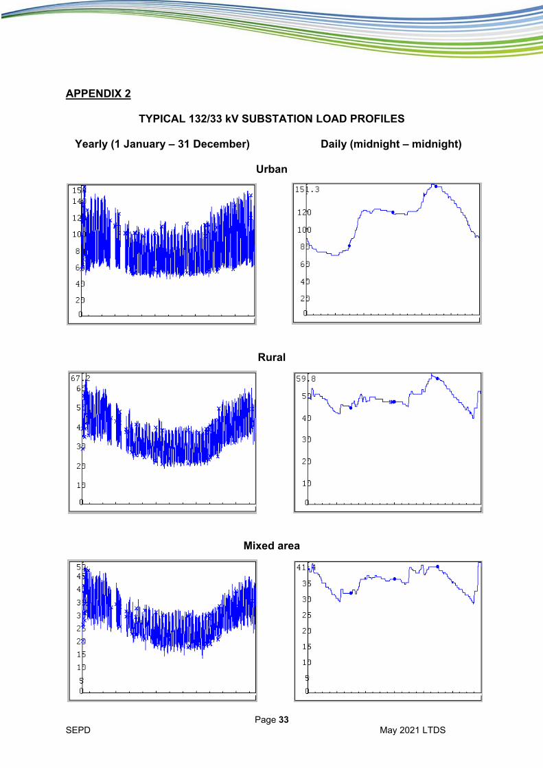
APPENDIX 2
TYPICAL 132/33 kV SUBSTATION LOAD PROFILES Yearly (1 January – 31 December) Daily (midnight – midnight)
Urban
Rural
Mixed area
Page 34 SEPD May 2021 LTDS
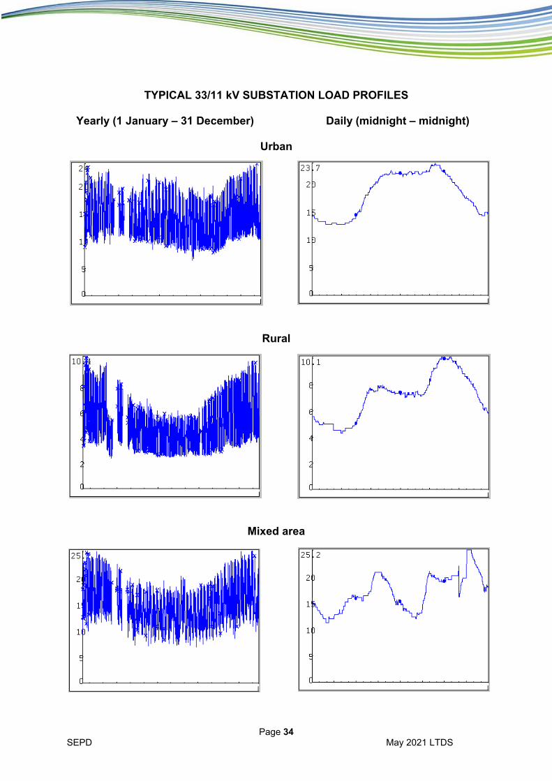
TYPICAL 33/11 kV SUBSTATION LOAD PROFILES Yearly (1 January – 31 December) Daily (midnight – midnight)
Urban
Rural
Mixed area

Page 35 SEPD May 2021 LTDS
APPENDIX 3
NETWORK DEVELOPMENT PROPOSALS
Network Reinforcement Projects
GSP Name Estimated
Completion Impact on Distribution
Network Capability Changes from previous LTDS
Amersham Denham 132/22KV Network - Reinforcement
Mar-22 Provide alternative connection to Denham (PSSE Node Number: 14610) for double circuit outages
None
Bramley Andover/Amesbury 132 kV reinforcement
Aug-22
Carry out 132 kV buswork at Andover (10710) substation to effectively swap Amesbury and Andover BSPs so that Andover is now supplied from Melksham and Amesbury is supplied from Bramley.
None
Bramley Reading to Little Hungerford to Arborfield - 33kV circuit reinforcement
Mar-22
Upgrade the circuits between Reading (21930), Little Hungerford (86804) and Arborfield (87101) to increase capacity and reconfigure the auto-changeover arrangement
Completion date changed from January 2021
Bramley Thatcham - Ashford Hill 132 kV circuit reinforcement
Mar-22
Install a new 132 kV dual circuit from Ashford Hill tee point to Thatcham 132 kV (24110) to maintain security of supply.
Completion date changed from December 2022
Chickerell Dorchester -Dorchester Town 33/11kV Substation Redevelopment
Sep-21
Reinforcement of the existing transformers with higher rated assets to increase the substation firm capacity at Dorchester Town primary (90002)
None
Cowley Bicester North Grid substation / East Claydon (NG substation)
Mar-22
Establish a new 132/33 kV substation at Bicester supplied from East Claydon GSP (55511) and transfer the Bicester (95310), Upper Heyford and Cottisford substation loads from Headington 132/33 kV. This will increase capacity on the 132 kV circuits from Cowley
None
Ealing Southfield Road 66/11 kV Transformer Replacement
Apr-23
Reinforcement of the existing transformers with higher rated assets to increase the substation firm capacity at Southfield Road primary (93003 and 93004)
None
Fawley Fawley South - 132kV Cable Reinforcement Fawley South
Sep-21
Overlay the section of 132kV underground cable on the Fawley North (15510) to Fawley South 1 (15608) circuit so that the thermal ratings match that of the overhead line
Completion date changed from April 2021

Page 36 SEPD May 2021 LTDS
GSP Name Estimated
Completion Impact on Distribution
Network Capability Changes from previous LTDS
Fleet Aldershot 132/33 kV substation / Fault Level Mitigation works
Oct-22 Fault Level Reinforcement - Replace fifteen 33kV CBs - 85100
None
Fleet Aldershot - Farnham 33 kV rutter pole replacement
Dec-24
Install two new 33 kV circuits between Aldershot (10130) and Farnham (87005, 87006) substations.
New project
Fleet Bordon and Alton/Fernhurst 33 kV reinforcement
Oct-22
Install a new 33 kV circuit between Bordon and Budds Lane, new switchgear at Bordon 33 kV (12130-12132) and split the Alton/Fernhurst BSPs
None
Fleet Camberley - Sandhurst 33 kV
Jun-21
Install two new 33kV cable circuits between Camberley (12730) and Sandhurst (87313) to replace the existing Rutter pole overhead line circuits.
Completion date changed from March 2021
Fleet Coxmoor Wood – Crookham rutter pole replacement
Aug-22
Install two new 33kV circuits between Coxmoor Wood (14130) and Crookham (87400) substations to mitigate an outage issue
None
Fleet Coxmoor Wood / Wrecclesham Rutter pole replacement
Dec-24
Install a new 33kV circuit between Coxmoor Wood (14130) and Wrecclesham (87406) substations to mitigate an outage issue
Completion date changed from December 2021
Fleet
Fernhurst - Five Oaks - Plaistow - overlay existing 33kV OHL and upgrade Plaistow Transformers
Feb-23
Install a new 33kV circuit between Fernhurst (87214) and Five Oaks (15830) substations to mitigate an outage issue as well as installing a new 33/11 kV transformer at Plaistow (87215)
Completion date changed from March 2022
Fleet Fernhurst - Plaistow 33kV reinforcement
Jun-21
Establish a new 33 kV, 15 km circuit from Fernhurst (15730) – Plaistow (21130). This will mitigate the low voltage issue and improve the quality of supply to our customers.
Completion date changed from January 2021
Fleet Fernhurst / Five Oaks Rutter pole replacement
Dec-22
Install a new 33kV circuit between Fernhurst (15730) and Five Oaks (15830) substations to mitigate an outage issue
Completion date changed from December 2021
Fleet Petersfield 33 kV reinforcement. Alton - Fernhurst split
Jun-22
Reconfigure and reinforce the 33 kV network between Petersfield 33 kV (21030), Alton 33 kV (10330) and Fernhurst 33 kV (15730) substations
Completion date changed from March 2021
Iver Slough 33 kV auto-close scheme
Sep-21 Install an auto-close scheme at Slough South 33 kV (23520) to maintain security of supply
Completion date changed from March 2021

Page 37 SEPD May 2021 LTDS
GSP Name Estimated
Completion Impact on Distribution
Network Capability Changes from previous LTDS
Lovedean Havant - Horndean / Waterlooville - Horndean Rutter pole replacement
Sep-24
Install a new 33kV circuit between Havant (16930) and Waterlooville (87803) and Horndean (88002) substations to mitigate an outage issue
Completion date changed from October 2021
Lovedean Hunston / Birdham / Selsey Rutter pole replacement
Jan-25
Install a new 33kV circuit between Hunston (17530), Birdham (11630) and Selsey (22930) substations to mitigate an outage issue
Completion date changed from December 2021
Lovedean Rose Green - Hunston rutter pole replacement
Jun-24
Install two new 33kV circuits between Rose Green (22330) and Hunston (17530) substations to mitigate an outage issue
Completion date changed from January 2022
Lovedean Shripney - Argyle Road - South Bersted - Under Grounding 33kV Circuits
Mar-22
Install four new 33kV circuits between Shripney (25430) and Argyle Road (10830) and between Shripney and South Bersted (22730) substations to mitigate an outage issue
Completion date changed from December 2020
Lovedean Shripney - Bilsham OHL rutter pole overlay
Sep-22
Install a new 33kV circuit between Shripney (23430) and Bilsham (11530) substations to mitigate an outage issue
Completion date changed from December 2020
Mannington Mannington 132/33 kV substation - Mill Lane 33/11 kV substation
Jul-24 Replacement of 400 A 33 kV isolators at Mannington (89250) and Mill Lane (89202)
Completion date changed from June 2023
Mannington Salisbury/Amesbury 132 kV Network Improvements
Dec-23
Installation of a 132 kV isolator at Amesbury 132 kV substation (10510-10513) and connection on to Salisbury/Amesbury tee 132 kV circuit 2.
Completion date changed from March 2024
Nursling Rownhams - North Baddesley 33 kV
Jun-23
Replacement of 1.5 km of dual circuit overhead line and 0.1 km of 33 kV cable between Rownhams (22430) and North Baddesley (88513 and 88514) substation
Completion date changed from June 2022
Nursling Velmore- Bishopstoke- Netley Common 33kV Cable circuit reinforcement
Dec-21
Install an additional circuit to supply Bishopstoke (24730) and Hedge End (88205) from Velmore (20230) and establish a normally open point for the circuit from Netley Common to Hedge End. This will increase the firm capacity at in the group and increase the transfer capacity between the two BSPs.
Completion date changed from September 2021

Page 38 SEPD May 2021 LTDS
GSP Name Estimated
Completion Impact on Distribution
Network Capability Changes from previous LTDS
Willesden Canal Bank 22/6.6kV System Reinforcement
Jan-24
Install two new 66 kV cables from Willesden to Canal Bank (92011) substation, two 66/11 kV 40 MVA transformers and a new 11 kV switchboard. It will also include a load transfer from Park Royal. This will create sufficient capacity for local development and improve security of supply in the area.
Completion date changed from September 2023
Willesden Leamington Park Substation - Uprate 6.6kV Network to 11kV
Dec-22 Install two 22/11 kV, 24 MVA transformers and new 11 kV switchgear (92128)
None
Willesden Willesden to Perivale 66kV cable scheme
Sep-22
Install a new 66/11 kV transformer connecting into the existing 66 kV Willesden (26860) – Greenford 2 circuit. This will increase the firm capacity at Perivale (92004) and improve the quality of supply to our customers.
Completion date changed from November 2021
Asset Replacement Projects
GSP Name Estimated
Completion Impact on Distribution
Network Capability Changes from previous LTDS
Amersham Loudwater 132/33 kV – Replace earthing transformers and LER
Oct-22 Increase Health Index Completion date changed from April 2021
Axminster Axminster 132kV Substation Replace 132kV Circuit Breakers
May-21 Increase Health Index Completion date changed from March 2021
Axminster Pulham – 11 kV switchgear replacement
Completed Increase Health Index N/A
Axminster Sherborne 33kV Switchgear & 33/11kV Transformer Replacement
Mar-23 Increase Health Index Completion date changed from May 2022
Axminster Wareham Town – 11 kV switchgear replacement
Jul-22 Increase Health Index None
Axminster Yeovil 33/11 kV Transformer Replacement
Jul-22 Increase Health Index Completion date changed from April 2022
Botley Wood Netley Common 132/33kV Substation - Replace A1MT, A2MT
Jun-23 Increase Health Index Completion date changed from June 2022
Bramley Barton Stacey 33/11 kV – Replace switchgear and transformer
Mar-22 Increase Health Index Completion date changed from May 2021

Page 39 SEPD May 2021 LTDS
GSP Name Estimated
Completion Impact on Distribution
Network Capability Changes from previous LTDS
Bramley Beenham - 33kV Switchgear Replacement
Jan-24 Increase Health Index Completion date changed from July 2022
Chickerell Cerne Abbas 33kV & 11kV Switchgear & 33/11kV Transformer Replacement
May-24 Increase Health Index Completion date changed from May 2022
Cowley Berinsfield 33 kV Switchgear Replacement
Jun-21 Increase Health Index None
Cowley Burford - 33kV Switchgear Replacement
Nov-22 Increase Health Index Completion date changed from February 2023
Cowley Cholsey 33/11kV Transformer Replacement
Mar-23 Increase Health Index Completion date changed from February 2022
Cowley Frenchay Road - 33 kV switchgear Replacement
Jun-21 Increase Health Index None
Cowley Harwell 132 kV – Replace isolators
Nov-21 Increase Health Index Completion date changed from April 2021
Cowley Sutton Courtenay - 33kV Switchgear Replacement
Jan-24 Increase Health Index Completion date changed from July 2022
Fawley Cowes 132kV Substation Replace 132kV CBs
Jun-21 Increase Health Index Completion date changed from March 2021
Fawley Fawley North - 11kV Switchgear Replacement
Mar-23 Increase Health Index Completion date changed from March 2022
Fawley Isle of Wight – Isolator replacement
Nov-22 Increase Health Index Completion date changed from December 2021
Fawley Lynes Common - 11kV Switchboard Replacement
Nov-22 Increase Health Index Completion date changed from October 2021
Fawley Lynes Common – Replace isolators
Nov-22 Increase Health Index Completion date changed from October 2021
Fawley Wootton Common 33kV Switchgear replacement
Oct-21 Increase Health Index None
Fleet Bordon 33 kV switchgear replacement
Completed Increase Health Index N/A
Fleet Reading - Reading Town 132kV Fluid Filled cable overlay
Feb-22 Increase Health Index Completion date changed from June 2021
Iver Grassingham Road 22/11/6.6 kV – Replace switchgear and transformer
Dec-23 Increase Health Index Completion date changed from December 2022
Page 40 SEPD May 2021 LTDS
GSP Name Estimated
Completion Impact on Distribution
Network Capability Changes from previous LTDS
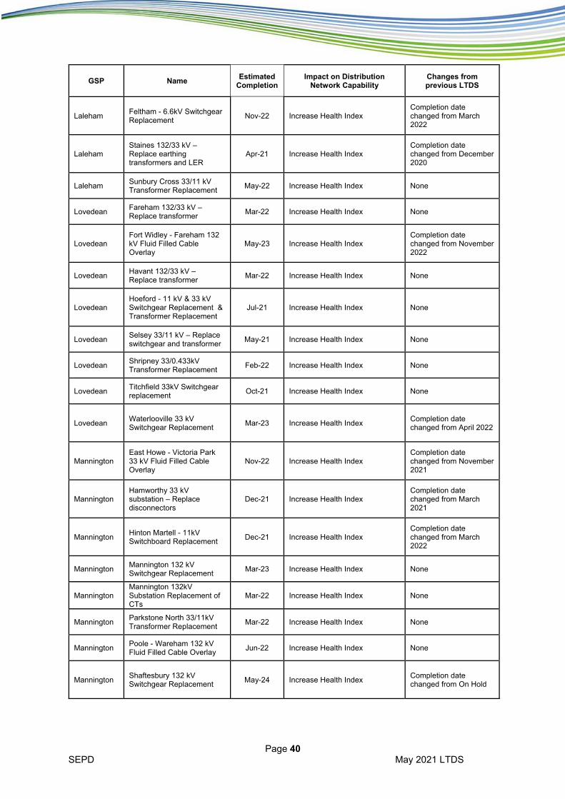
Laleham Feltham - 6.6kV Switchgear Replacement
Nov-22 Increase Health Index Completion date changed from March 2022
Laleham Staines 132/33 kV – Replace earthing transformers and LER
Apr-21 Increase Health Index Completion date changed from December 2020
Laleham Sunbury Cross 33/11 kV Transformer Replacement
May-22 Increase Health Index None
Lovedean Fareham 132/33 kV – Replace transformer
Mar-22 Increase Health Index None
Lovedean Fort Widley - Fareham 132 kV Fluid Filled Cable Overlay
May-23 Increase Health Index Completion date changed from November 2022
Lovedean Havant 132/33 kV – Replace transformer
Mar-22 Increase Health Index None
Lovedean Hoeford - 11 kV & 33 kV Switchgear Replacement & Transformer Replacement
Jul-21 Increase Health Index None
Lovedean Selsey 33/11 kV – Replace switchgear and transformer
May-21 Increase Health Index None
Lovedean Shripney 33/0.433kV Transformer Replacement
Feb-22 Increase Health Index None
Lovedean Titchfield 33kV Switchgear replacement
Oct-21 Increase Health Index None
Lovedean Waterlooville 33 kV Switchgear Replacement
Mar-23 Increase Health Index Completion date changed from April 2022
Mannington East Howe - Victoria Park 33 kV Fluid Filled Cable Overlay
Nov-22 Increase Health Index Completion date changed from November 2021
Mannington Hamworthy 33 kV substation – Replace disconnectors
Dec-21 Increase Health Index Completion date changed from March 2021
Mannington Hinton Martell - 11kV Switchboard Replacement
Dec-21 Increase Health Index Completion date changed from March 2022
Mannington Mannington 132 kV Switchgear Replacement
Mar-23 Increase Health Index None
Mannington Mannington 132kV Substation Replacement of CTs
Mar-22 Increase Health Index None
Mannington Parkstone North 33/11kV Transformer Replacement
Mar-22 Increase Health Index None
Mannington Poole - Wareham 132 kV Fluid Filled Cable Overlay
Jun-22 Increase Health Index None
Mannington Shaftesbury 132 kV Switchgear Replacement
May-24 Increase Health Index Completion date changed from On Hold
Page 41 SEPD May 2021 LTDS
GSP Name Estimated
Completion Impact on Distribution
Network Capability Changes from previous LTDS
Mannington Stapleford 33/11kV Transformer Replacement
Mar-23 Increase Health Index Completion date changed from May 2022
Mannington Victoria Park - 33kV Switchgear Replacement
Mar-23 Increase Health Index Completion date changed from March 2022
Mannington Winfrith Heath - 11 kV switchboard Replacement
Dec-22 Increase Health Index Completion date changed from May 2022
Melksham Andover - 33kV Switchgear Replacement
May-23 Increase Health Index Completion date changed from March 2022
Melksham Chippenham - Sutton Benger 33 kV circuit replacement
Mar-25 Remove maintenance restriction Completion date changed from March 2023
Melksham Frome - 33kV Switchgear Replacement
Mar-23 Increase Health Index None
Melksham Melksham Town 11kV Switchboard Replacement
May-22 Increase Health Index None
Melksham Thruxton 33/11kV Transformer Replacement
Jan-22 Increase Health Index Completion date changed from April 2021
Minety Cirencester - Whiteway 33 kV Fluid Filled Cable Replacement
Jun-24 Increase Health Index Completion date changed from June 2022
Minety Shipton Oliffe – Replace transformer
Completed Increase Health Index N/A
Minety Stanton Fitzwarren 33kV Switchgear & 33/11kV Transformer Replacement
May-22 Increase Health Index None
Minety Swindon - 33 kV Switchgear Replacement
Oct-22 Increase Health Index Completion date changed from March 2022
North Hyde
Replacement of North Hyde - Osterley and North Hyde - Vicarage Farm Rd 66kV cables
May-24 Increase Health Index Completion date changed from May 2022
Nursling Bishopstoke 33/11 kV Transformer Replacement
Mar-22 Increase Health Index None
Nursling Dunbridge - 11 & 33 kV Switchgear Replacement/Refurbishment
Mar-24 Increase Health Index Completion date changed from November 2022
Nursling Maybush - 11kV Switchboard Replacement
May-23 Increase Health Index Completion date changed from May 2022
Nursling Romsey - 11kV Switchboard Replacement
May-23 Increase Health Index Completion date changed from May 2022

Page 42 SEPD May 2021 LTDS
GSP Name Estimated
Completion Impact on Distribution
Network Capability Changes from previous LTDS
Nursling Rownhams 132 kV Substation - Switchgear replacement
Jul-21 Increase Health Index Completion date changed from March 2021
Nursling Southampton - Woodmill Lane - Regents Park 33kV Fluid Filled Cable Overlay
Feb-27 Increase Health Index Completion date changed from March 2023
Nursling St Cross 11kV Switchgear & 33/11kV Transformer Replacement
May-23 Increase Health Index Completion date changed from May 2022
Nursling St. Cross - Gordon Road 33kV Fluid Filled Cable Replacement
Dec-21 Increase Health Index None

Page 43 SEPD May 2021 LTDS
Assets Decommissioned
GSP Name Asset Type From PSSE Bus To PSSE Bus
Cowley Oxford (Osney)
33 kV Switchgear 20920 N/A
Fawley Cowes 132 kV Switchgear 13910, 13920 N/A
Lovedean Fareham 132/33 kV Transformer A2MTA 15312 15330
Lovedean Havant 132/33 kV Transformer A2MTB 16911 16930
Lovedean Havant 33 kV Switchgear 16930 N/A
Lovedean Wymering 132/33 kV Transformer A4MT 26113 26130
Melksham Amesbury 132/33 kV Transformer A1MTA 10511 10530