sorting of product based on color and rfidkavediasir.yolasite.com/resources/sorting of...
TRANSCRIPT

Sorting of Product based on Color and RFID
What is RFID?
RFID is simply Radio Frequency Identification.
“Radio Frequency Identification is an automatic identification method, relying on storing and remotely retrieving data using devices called tags.”
RFID is similar to bar code technology but uses radio waves to capture data from tags, rather than optically scanning the barcodes on a label. RFID does not require the tag or label to “in line of sight” to read — that's one of the key characteristics of an RFID system.
How does an RFID system work?
For RFID systems to work the following components are essential: -
Tag (Passive, semi passive or active) Reader (also known as an antenna or integrator) Software (also known as middleware)
Information is sent to and read from RFID tags by a reader using radio waves. In passive systems, which are the most common, an RFID reader transmits an energy field that “wakes up” the tag and provides the power for the tag to respond to the reader. In active systems, a battery in the tag is used to boost the effective operating range of the tag and to support additional features over passive tags, such as temperature sensing. Data collected from tags is then passed through communication interfaces (cable or wireless) to host computer systems in the same manner that data scanned from bar code labels is captured and passed to computer systems for interpretation, storage, and action.
What is an RFID Tag?
RFID tags come in many shapes and sizes each suited to a specific application, but all RFID tags can be generally grouped into two main categories, regardless if they are encased, a sticky label or just a solid button like tag.
RFID tags are either “passive” (no battery) or “active” (self-powered by a battery). RFID tags also can be read-only (stored data can be read but not changed), read/write (stored data can be altered or rewritten), or a combination,

in which some data is permanently stored while other memory is left accessible for later encoding and updates.
Passive RFID Tags
Passive RFID tags have no internal power supply. An electrical current induced in the antenna by the incoming radio frequency signal provides just enough power for the integrated circuit (IC) in the RFID tag to power up and transmit a response.
RFID tags communicate in various ways with the RFID reader. The aerial (antenna) has to be designed to both collect power from the incoming signal and also to transmit the outbound signal.
Lack of an onboard power supply means that the passive RFID tag can be quite small: commercially available products exist that can be embedded under the skin. As of 2006, the smallest passive RFID tag measured 0.15 mm × 0.15 mm, and are thinner than a sheet of paper (7.5 micrometers).
Passive RFID tags have practical read distances ranging from about 10 cm (4 in.) (ISO 14443) up to a few meters (EPC and ISO 18000-6) depending on the chosen radio frequency and antenna design/size.
Due to their simplicity in design they are also suitable for manufacture with a printing process for the antennas. Passive RFID tags do not require batteries and can be much smaller, and have an unlimited life span. Simple laboratory printed polymer tags operating at 13.56 MHz were demonstrated in 2005 by both PolyIC (Germany) and Philips (The Netherlands). If successfully commercialized, polymer tags will be roll printable, like a magazine, and much less expensive than silicon-based tags. The end game for most item level tagging over the next few decades is that RFID tags will be wholly printed - the same way a barcode is today - and be virtually free, like a barcode.
Active RFID Tags
Unlike passive RFID tags, active RFID tags have their own internal power source which is used to power any intergrated circuits that generate the outgoing signal. Active RFID tags are typically much more reliable than passive tags due to the ability for active tags to conduct a "session" with a reader.

Active RFID tags, due to their onboard power supply, also transmit at higher power levels than passive tags, allowing them to be more effective in "Radio Frequency challenged" environments like water (including humans/cattle, which are mostly water), metal (shipping containers, vehicles), or at longer distances. Many active tags have practical ranges of hundreds of meters, and a battery life of up to 10 years. Some active RFID tags include sensors such as temperature logging which have been used in concrete maturity monitoring or to monitor the temperature of perishable goods. Other sensors that have been married with active RFID include humidity, shock/vibration, light, radiation, temperature and atmospherics like ethylene.
Active tags typically have a much longer range (approximately 300 feet) and larger memories than passive tags, as well as the ability to store additional information sent by the transceiver.
What is an RFID Reader?
An RFID reader is basically a radio frequency (RF) transmitter and receiver, controlled by a microprocessor or digital signal processor (DSP). The RFID reader, using an attached antenna, captures data from RFID tags, and then passes the data to a computer for processing. As with tags, readers come in a wide range of sizes and offer different features. Readers can be affixed in a stationary position (for example, beside a conveyor belt in a factory or dock doors in a warehouse), portable (integrated into a mobile computer that also might be used for scanning bar codes), or even embedded in electronic equipment such as print-on-demand label printers.

What is RFID Software (middleware)?
So far your RFID system is communicating in radio waves, so software is used to decipher the radio waves into logical terms.
This software can either be separate from your RFID Reader and be stored on a PC or laptop, or it may be integrated into the RFID Reader as with portable devices such as the Datalogic Jet.
This software is like any other piece of software and variations are limitless.
What RFID Frequency should I use?
The RFID frequency you should use for a particular RFID application purly depends on the application and the environment in which the RFID
Low Frequency (LF) - Low Frequency range 70 – 150khz
Animal tracking/husbandry
High Frequency (HF) - High Frequency 13.56MHz
Tote trackng conveying systems
Ultra High Frequency (UHF) - Ultra High Frequency 866Mhz
Logistics supply chain
Call us and we will be able to advise which RFID frequency would be best suited to your application requirements.
What can RFID systems be used for?The full potential of RFID as not yet been explored, typically RFID systems are used to:
Supply chain management Membership admission/access control Work in Progress (WIP) Vehicle Tracking Asset Tracking
RFID can be also used in the following areas: -

RFID Systems in Manufacturing
Keeping track of any production process is key in the manufacturing industry. Whether tracking car bodies in a production plant, monitoring an engine build, or simply adding ingredients in food production.
RFID is well established in the manufacturing industry, and as a result, a wide range of tags are available, specifically designed for high temperature applications, washing facilities and encapsulation into plastics enable them to work in the harshest environments found in the manufacturing industries.
In addition all the major industrial bus networks are available for interface purposes enabling you to seamlessly integrate RFID technology into your processes.
RFID can help with: -
Pallet tracking Part Traceability Production line processing Robot Cells and Automation Systems
RFID Tracking Systems in logistics/distribution
Having the ability to securely track and trace documents, parcels and products throughout the world has become more significant.
Postal and courier companies operate within highly complex distribution chains on a daily basis and face increasing pressure to improve efficiencies. Manufacturers are demanding more effective tracking of their reusable assets such as trays, pallets, roll-cages, totes and kegs in order to reduce cost and improve return on the investment for those assets. RFID can help!
RFID enables Postal and courier companies to accurately pinpoint which consignments have passed through which depots and when, enabling them to easily produce reports for their customers.
RFID can help with: -
Roll cage consolidation Parcel tracking Reusable asset tracking Inventory Control

RFID Tracking Systems in the supply chain
Accurate identification and tracking of goods is essential in today's highly competitive retail market.
More than ever before, there is pressure on manufacturers, distributors and retailers to maximise efficiency, minimise cost and provide the best possible value for the end-consumer. Whether it’s tracking wooden or plastic pallets, or simply monitoring the flow of parcels through a distribution hub.
RFID can help with: -
Parcel Consignment Pallet tracking Mobile RFID Solutions Proof of Delivery
RFID Systems in the office
In today’s fast moving world “time is money” and efficiency is the key. In many companies asset tracking is a very important part of the day-to-day running of an office. Knowing where assets, such as people, furniture, documentation, telephones and IT equipment, are can be crucial in an efficient office environment.
Using RFID can help with managing the control of the assets complete with historical information on here the assets have been etc. on the “tagged” part.
Tags are available in a variety designs for specific applications.
RFID can help with: -
Asset Tracking & Management Tracking legal documents Access entry systems Library Applications
RFID increases visibility in the value chain
RFID tags can be attached to almost anything today and registrations placed at strategic processing points can provide visibility throughout the logistics chain. RFID can be used to provide:
Real-time information about when the trailer has left a hub and when it is scheduled to arrive at a sorting centre or the actual time of arrival

Volume forecasts right down to each vehicle and precise feedback to transport planning systems. This can cut transport expenses and provides a total overview of the utilization of the transport systems
Automatic stock control of load carriers loaded and unloaded at customer locations, automatically generating valuable PoC and PoD documentation.
Automatic real-time tracking of large customer shipments for dedicated visibility and performance services to key customers, e.g. high-value items
Color SensorThe TCS3200 and TCS3210
programmable color light-to-frequency converters that combine configurable silicon photodiodes and a current-to-frequency converter on a single monolithic CMOS integrated circuit. The output is a square wave (50% duty cycle) with frequency directly proportional to light intensity (irradiance). The full-scale output frequency can be scaled by one of three preset values via two control input pins. Digital inputs and digital output allow direct interface to a microcontroller or other logic circuitry.
Output enable (OE) places the output in the high-impedance state for multiple-unit sharing of a microcontroller input line. In the TCS3200, the light-to-frequency converter reads an 8 x 8 array of photodiodes. Sixteen photodiodes have blue filters, 16 photodiodes have green filters, 16 photodiodes have red filters, and 16 photodiodes are clear with no filters. In the TCS3210, the light-to-frequency converter reads a 4 x 6 array of photodiodes. Six photodiodes have blue filters, 6 photodiodes have green filters, 6 photodiodes have red filters, and 6 photodiodes are clear with no filters.
The four types (colors) of photodiodes are interdigitated to minimize the effect of non-uniformity of incident irradiance. All photodiodes of the same color are connected in parallel. Pins S2 and S3 are used to select which group of photodiodes (red, green, blue, clear) are active. Photodiodes are 110 μm x 110 μm in size and are on 134-μm centers


APPLICATION INFORMATIONPower supply considerations:
Power-supply lines must be decoupled by a 0.01-μF to 0.1-μF capacitor with short leads mounted close to the device package.
Input interface:A low-impedance electrical connection between the device OE pin and the
device GND pin is required for improved noise immunity. All input pins must be either driven by a logic signal or connected to VDD or GND should not be left unconnected (floating).
Output interface:The output of the device is designed to drive a standard TTL or CMOS
logic input over short distances. If lines greater than 12 inches are used on the output, a buffer or line driver is recommended. A high state on Output Enable (OE) places the output in a high-impedance state for multiple-unit sharing of a microcontroller input line.
Power downPowering down the sensor using S0/S1 (L/L) will cause the output to be
held in a high-impedance state. This is similar to the behavior of the output enable pin, however powering down the sensor saves significantly more power than disabling the sensor with the output enable pin. Photodiode type (color) selection The type of photodiode (blue, green, red, or clear) used by the device is controlled by two logic inputs, S2 and S3
Output frequency scaling:Output-frequency scaling is controlled by two logic inputs, S0 and S1. The
internal light-to-frequency converter generates a fixed-pulse width pulse train. Scaling is accomplished by internally connecting the pulse-train output of the converter to a series of frequency dividers. Divided outputs are 50%-duty cycle square waves with relative frequency values of 100%, 20%, and 2%. Because division of the output frequency is accomplished by counting pulses of the principal internal frequency, the final-output period represents an average of the multiple periods of the principle frequency.
The output-scaling counter registers are cleared upon the next pulse of the principal frequency after any transition of the S0, S1, S2, S3, and OE lines. The output goes high upon the next subsequent pulse of the principal frequency, beginning a new valid period. This minimizes the time delay between a change on the input lines and the resulting new output period. The response time to an input programming change or to an irradiance step change is one period of new frequency plus 1 μs. The scaled output changes both the full-scale frequency and the dark frequency by the selected scale factor. The frequency-scaling function allows the output range to be optimized for a variety of measurement techniques. The scaled-down outputs may be used where only a slower

frequency counter is available, such as low-cost microcontroller, or where period measurement techniques are used.
Measuring the frequency:The choice of interface and measurement technique depends on the
desired resolution and data acquisition rate. For maximum data-acquisition rate, period-measurement techniques are used. Output data can be collected at a rate of twice the output frequency or one data point every microsecond for full-scale output. Period measurement requires the use of a fast reference clock with available resolution directly related to reference clock rate. Output scaling can be used to increase the resolution for a given clock rate or to maximize resolution as the light input changes. Period measurement is used to measure rapidly varying light levels or to make a very fast measurement of a constant light source.
Maximum resolution and accuracy may be obtained using frequency-measurement, pulse-accumulation, or integration techniques. Frequency measurements provide the added benefit of averaging out random- or high-frequency variations (jitter) resulting from noise in the light signal. Resolution is limited mainly by available counter registers and allowable measurement time. Frequency measurement is well suited for slowly varying or constant light levels and for reading average light levels over short periods of time. Integration (the accumulation of pulses over a very long period of time) can be used to measure exposure, the amount of light present in an area over a given time period.


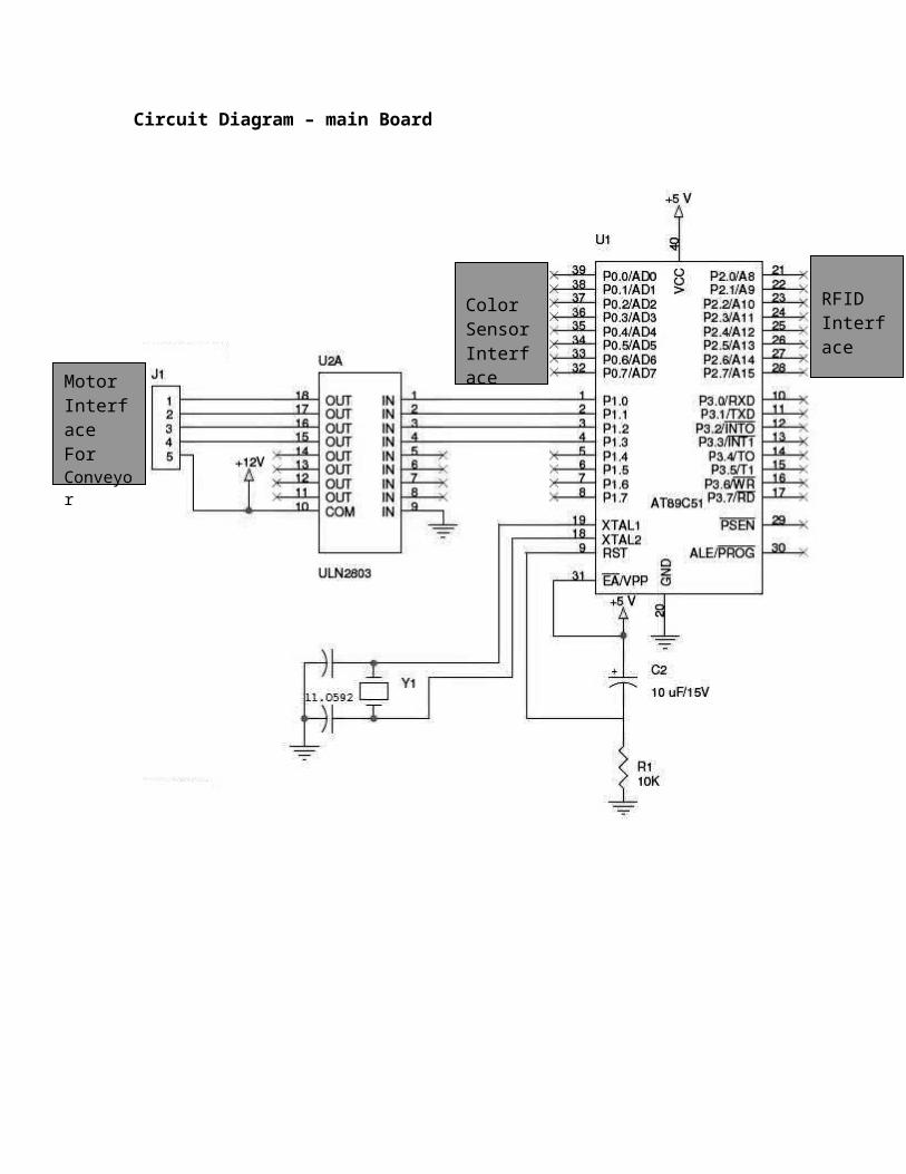
Circuit Diagram – main Board
Color SensorInterface
RFIDInterface
MotorInterfaceForConveyor

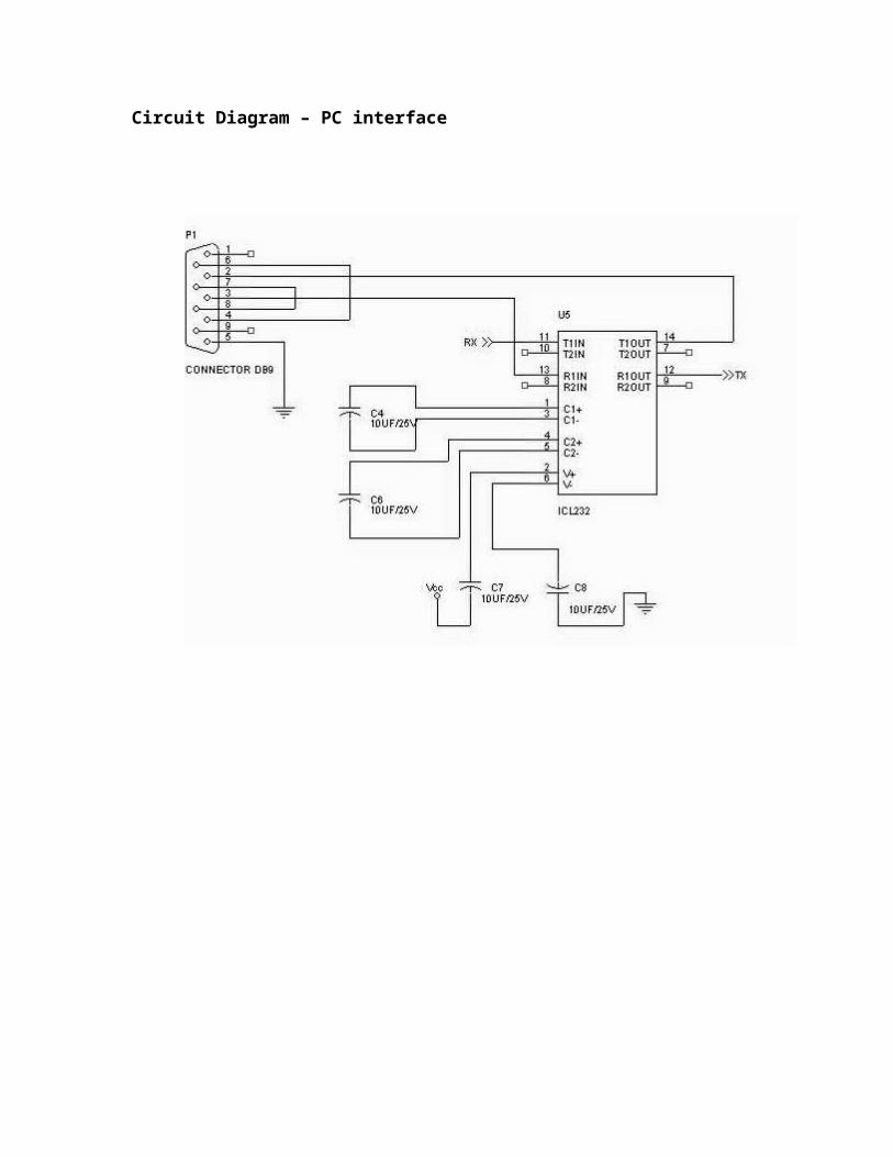
Circuit Diagram – PC interface

Circuit Diagram _ Color Sensor Interface
P0.0P0.1
P0.2
P0.3
P0.4P0.5
Connected to Port P0 of the port 0 of 89c51
Circuit Diagram – RFID Interface
P1.0P1.0
P1.1
P1.2
P1.3
Connected to Port P1 of the port 0 of 89c51
Assembly for Sorting of Parcel

Hardware and Software Requirement1.Pentium-4 Based System2.1GB RAM3.100MB of HardDisk4.System Hardware5.LCD/CRT color Monitor
Software1.Windows XP 2.Visual Basic 6.03.DataBase Software (MS-Acess)4.Drivers of RFID interface 5.Side 51 / keil / EDSim51 any 8051 editor
Component ListSrno Component Quantity
1 89c51 22 10k resistor Network 63 40pin socket 34 Max232 25 16pin socket 46 20 pin socket1 27 14pin socket 28 RFID reader 19 RFID Tags 510 Main Board OCB 311 Motor 30RPM geared 612 10uF capacitor 1213 9 pin male Female Connector 214 Regulator 7805 315 Bridge Rectifier 316 IN4001 1217 11.0593Mhz Crystal 318 Transformer (0-9v , 1Amp) 219 100-uf Capacitor 320 0.1uf capacitor 621 ULN2803 322 Relimate connector 9pin 12

Benefit and Application of RFID and Color Sorting
As a conclusion we can state that tagging mail and mailboxes would result in:
Overall reduced rate of mail delivery error Less human errors -> more efficient working hours in sorting and
deliveries Satisfied customers who trust the system Less money spent on investigating lost mail Less money spent on insurances for lost mai Real-time up-to-date database 100% exact mail traceability service for customers Less vandalism of mailboxes Reduced handling costs for customers -> increased competitiveness More efficient and flexible operations -> shorter delivery times Enhanced security and safety Cheaper return package costs (for online shopping)