sorin draghici, dept. of computer science, wayne state ...sod/ijns1997.pdf · a neural network...
TRANSCRIPT

A neural network based artificial vision system for licence plate recognition
Sorin Draghici, Dept. of Computer Science, Wayne State University,
Abstract
This paper presents a neural network based artificial vision system able to analyse the image of a car given
by a camera, locate the registration plate and recognise the registration number of the car. The paper
describes in detail various practical problems encountered in implementing this particular application and
the solutions used to solve them.
The main features of the system presented are: controlled stability-plasticity behaviour, controlled reliability
threshold, both off-line and on-line learning, self assessment of the output reliability and high reliability
based on high level multiple feedback.
The system has been designed using a modular approach which allows easy upgrading and/or substituting of
various sub-modules thus making it potentially suitable in a large range of vision applications.
The OCR engine was designed as an interchangeable plug-in module. This allows the user to choose an
OCR engine which is suited to the particular application and to upgrade it easily in the future. At present,
there are several versions of this OCR engine. One of them is based on a fully connected feedforward
artificial neural network with sigmoidal activation functions. This network can be trained with various
training algorithms such as error backpropagation. An alternative OCR engine is based on the constraint
based decomposition (CBD) training architecture.
The system has showed the following performances (on average) on real-world data: successful plate
location and segmentation about 99%, successful character recognition about 98% and successful
recognition of complete registration plates about 80%.
Keywords: vision, OCR, neural networks, car licence plate, real-world application

A neural network based artificial vision system for licence plate recognition
Sorin Draghici1, Dept. of Computer Science, Wayne State University,
1. Introduction
This paper presents a neural network based artificial vision system -Visicar - and its applications. The
system is able to analyse the image of a car given by a camera, locate the registration plate and recognise
the registration number of the car. The paper describes in details various practical problems encountered in
implementing this particular application and the methods used to solve them.
The paper is structured as follows. Section 2 presents some problems which create the need for such a
system. Section 3 describes the system and is divided into two sub-sections. Section 3.1 presents the
structure of the system whereas section 3.2 gives a detailed description of the processing performed by the
system. Section 4 describes briefly the performances achieved by the system and section 5 presents some
conclusions.
2. Security problems which create the need for such a system
This section describes briefly some situations in which non-trivial security problems can be solved by using
such an artificial vision system.
Parking areas with no special security requirements. It might seem that such areas do not require any
security system. In reality, fraudulent practice is rather common and brings important losses to companies
which manage parking areas and garages.
A common fraudulent practice is to use two cars in order to occupy permanently a space in a parking lot.
One can enter in the car park with a car A (a Ferrari for instance) and obtain a ticket TA stamped with the
time of entrance T1. At any later date, the same person can enter with a car B (an old Mini for instance) and
1 This research was supported in part by Eurotronic srl, Rome, Italy. Most experiments in the field were
performed using installations and equipment kindly made available by Autostrade spa. The author wishes to
thank Dott. Giovanni Mazza, managing director of Eurotronic srl for his help and encouragement and
Stefano Capello, technical manager of Comerson for his technical support for the video equipment.

obtain a ticket TB stamped with the time of entrance T2. Then, the person can leave car B in the car park,
and leave the car park at time T2+ε with car A and ticket TB, paying just the minimum amount due for the
time ε. Later on, car A will be deposited again in the car park with a ticket TA’ which will be used to exit
the car park with car B (paying again just a minimum fee). The process is then repeated, always swapping
cars and exiting the car park with the most recent ticket. Thus, an expensive Ferrari can be kept in a safe car
park for unlimited lengths of time, almost free, with huge losses for the car park company.
Another typical situation is that of a car theft. A thief can enter a car park with their own car A obtaining a
ticket TA, steal a very expensive car B and leave quietly with the stolen car and the ticket TA. This type of
fraud brings huge losses for car park companies materialised in high insurance costs.
One can imagine a system which recognises automatically the car number plate when the car enters the
parking area and stores somehow the registration number on the ticket. Later, when the car leaves the
parking lot, the system can check the correspondence between the information on the ticket and the
registration number of the car. It is easy to appreciate that such a system would eliminate completely both
fraud situations described above or at least, reduce their number.
Parking areas with security requirements. In these situations, such a system adds a further level of security
by granting entrance only to registered vehicles.
Toll payment. A system able to recognise registration plates can be used to identify vehicles which transit
through the toll gates. Such a system can be used to achieve two types of goals. Firstly, the system can be
used in conjunction with a database containing registration data and owners’ information in order to debit
the amount due directly into the car owner’s account. This can greatly reduce the running costs of the toll
bridge or motorway by reducing or eliminating the need for a human presence.
Secondly, such a system can be used as a back-up system which deals only with fraudulent vehicles. For
instance, in Italy, the motorway system is run by a private company called “Autostrade spa”. This company
has perfected a remote sensing system called “Telepass” which is able to identify certain vehicles which are
fitted with a special device. Those vehicles are allowed to transit without stopping through certain dedicated
channels at the toll gates, thus eliminating queuing. However, fraudulent users can transit those dedicated

channels without having the device fitted to their cars thus trying to avoid paying the toll. In such cases, a
Visicar-like system can be triggered. The system would automatically identify the car and, in conjunction
with a database, can identify the owner of the car and even issue a fine.
Restricted access areas. The system can be used to identify the abuses in any situation in which the traffic is
restricted. For instance, the historical centres of cities like Rome, Florence, etc. are closed to the public
traffic. Nonetheless, many people just ignore this and transit the respective areas. Reinforcing the law is
very difficult due to the great number of points of access in such areas. Theoretically, each such point would
necessitate a traffic warden. A Visicar-like system can substitute a human presence and still detect any
instances of breaking the law.
Railway traffic control and management. Artificial vision systems placed in various strategic positions can
yield important data which can be important for the control of the railway traffic.
3. Description of the system
3.1 The structure of the system
The system is composed of a camera, a frame grabber, a general purpose computing device (such as an
IBM-PC compatible computer, a workstation, etc.) and software for image analysis and character
recognition. Most of the software was written in C/C++ and is portable2. The system is triggered by an
external signal (such as that coming from a suitably positioned infra-red barrier or other sensors), it acquires
and stores the image of the car (which is presumably in front of the camera) and analyses the image with the
purpose of finding and recognising the car number plate. A possible set-up for a parking lot is shown in Fig.
1. Some examples of the images captured by the system are presented in Fig. 2 and the block structure of
the software system is presented in Fig. 3.
3.2 The functioning of the system
The main steps of the processing are: image acquisition and enhancement, plate location and segmentation,
character segmentation, character recognition, character validation and registration number validation (see
Fig. 3). Each of these steps will be described in detail in the following.
2 The software was compiled on various platforms including AIX, Unix, Linux, Dos, etc with compilers
from Microsoft, Borland, GNU, etc.

in Camera
Barrier
Infrared sensor
Fig. 1 The system setup for a parking lot
Fig. 2 Some examples of images captured by the system in various external conditions. The first three images (starting from the top left) were captured during daytime. The last three were captured during the night. Picture #2 has a strong back lighting, picture #3 contains a plate with the last character obscured by dirt (7?, Y?, 1?) and picture #6 has a very strong luminance gradient on the horizontal direction.

3.2.1 Plate location
3.2.1.1 Approach
The approach used for the plate location was to scan the image horizontally looking for repeating contrast
changes on a scale of 15 pixels3 and more. This approach uses the assumptions that the contrast between the
characters and the background of the plate is sufficiently good, that there are at least 3-4 characters on a
plate and that the characters have a minimum vertical size of about 15 pixels (note that this can always be
achieved by adjusting the optics of the camera).
Fig. 3 The block structure of the system
3 The particular value of 15 pixels is determined by the resolution of the camera/frame grabber, the optics
used for the camera, the average distance from the camera to the car and the real size of the characters. The
average distance from the camera to the car is determined by the range of car speeds for which the system
should work properly and the time delay introduced by the triggering device, camera and frame grabber.
Modifying this value is a part of the adjustment the software has to undergo for use with different
hardware. This value can also be determined empirically by analyzing several images for different car
speeds.

3.2.1.2 Processing
A gaussian blur filter is applied to eliminate the fine grain noise. Then, the system calculates the histogram
of the image and stretches the histogram with:
new_pixel=pixel*gamma + beta
where gamma and beta are calculated so that the stretched histogram will extend on the entire range of grey
levels available (from 0 to 255).
Subsequently, the program scans the image looking for areas with high contrast gradients at the given scale
of about 15 pixels. The resulting image is scanned again looking for concentrations of such high contrast
gradient areas. Any concentration of such areas which can be approximated by a rectangle will be signalled
as an interest zone. All subsequent processing will be performed in turn on each interest zone.
The first step performed on an interest zone is an image enhancement through another histogram stretching.
Fig. 4 shows the results of this first enahancement on 4 different interest zones.
Fig. 4 Some processing of 4 interest areas. The first image in each group shows the interest zone in the original image (resampled). The second one shows the same area after histogram analysis and enhancement.
3.2.2 Plate segmentation
3.2.2.1 Approach
The plate segmentation is performed using a differential gradient edge detection approach. The processing
speed is improved by approximating the magnitude of the local edge with the maximum of the absolute
values of the gradients on the x and y directions [Abdou, 1979; Foglein, 1983; Davies, 1990]. The
reliability is improved by gaussian filtering the edge image and averaging over different edge sensitivities.

This approach made the assumptions that the area of the interest zone which actually contains the characters
is characterised by a high spatial gradient of intensity (i.e. many character edges). Furthermore, it was
assumed that the characters are distributed on one or more rows which are more or less horizontal (see Fig.
6) and the horizontal distribution of the characters is more or less uniform (e.g. one does not have
intercharacter spaces larger than two characters).
3.2.2.2 Processing
First, the system performs a sobel operation with average preserving templates for vertical and horizontal
edges. The result of this operation is binarised with a given threshold4 and filtered with a gaussian filter.
The result is binarised again. Lateral histograms are calculated by projecting vertically and horizontally the
resulting binary image. These two lateral histograms will show the number of white pixels (corresponding to
edges in the original image) for each vertical and horizontal co-ordinate.
The above steps are repeated a given number of times using different thresholds in the binarisation step, and
average horizontal and vertical histograms are calculated. These histograms are smoothed with a one-
dimensional gaussian filtering. The averaging will increase the signal/noise ratio eliminating a lot of noise
and preserving only those edges coming from salient features of the image. Usually, the system performs
between 9 and 16 sobel-gauss-threshold cycles. Experiments showed that this averaged sobel-gauss-
thresholding combination is essential and it is able to eliminate many problems like non-uniform
illumination, reflections, dirt, etc. The exact number of cycles is decided by the system on an ad-hoc basis
depending on the quality of the image and the results obtained.
Next, the system will determine the probable limits of the plate by analysing the horizontal and vertical
histograms.
Note that one can always take into consideration the real size of the characters and adjust (once!) the
distance camera-target and the optics in such a way that characters are reasonably large on the image. As
one of the consequences, the inherent errors introduced by the edge detection mechanism are typically
bellow 5% (1-2 pixels for a character size of 40x100 pixels) and therefore not significant for the subsequent
processing.
3.2.3 Character segmentation
3.2.3.1 Approach
The character segmentation is performed in the following two steps:
4 This threshold can be calculated from the histogram of the sobel-filtered image or can be fixed (set
empirically for a better speed).

• Find the number and location of the horizontal group(s) using binarisation and lateral histogram
analysis.
• For each horizontal group, find the number and location of the characters which form the group using
lateral histogram analysis.
The lateral histogram analysis approach was considered the most suitable for this particular application
because the edges of the characters can be blurred, noise of various types can partially cover characters or
make connections between different characters and/or characters and borders (see Fig. 5). In all these
situations, classical methods based on morphological analysis of the characters (dilate, erode, closure,
skeleton analysis, etc.) and edge detection [Davies, 1990; Marr, 1980] showed to be rather unreliable.
Fig. 5 Examples of plates with partially occluded characters. Note that in the second plate, the dirt connects two characters with the border.
This approach makes the following assumptions. Firstly, it is assumed that the characters which form the
registration number are grouped together in one or two horizontal groups. If there are two horizontal
groups, their heights do not overlap (see Fig. 6). There is no restriction for the number of characters and
nor are these characters supposed to respect a specific format.
Fig. 6 Hypothesis used in the character segmentation stage. The first two images are acceptable. The last one is not.
3.2.3.2 Processing steps
3.2.3.2.1 Binarisation of the interest zone.
Theoretically, the interest zone contains a number of characters of one colour (e.g. black) on a background
of a different colour (e.g. white). However, the colours are not known and can vary from one plate to
another. Furthermore, usually there are gradients of colour and/or intensity both on the characters and in the
background. In order to ease the burden of subsequent character segmentation and recognition, it is useful
to normalise the interest zone transforming it into a standard binary image with (say) white characters on a
black background.
In an ideal case, the histogram of the gray level image of the interest zone is bimodal, having a peak which
corresponds to the background colour and another peak for the foreground (character) colour. If a
significant minimum is found in-between the two peaks, it can be chosen as the required threshold value.
Usually, it is known whether the objects of interest are dark on a light background or light on a dark
background. However, in this particular application, this information is not available and further analysis is
necessary to decide whether an inversion of the image is necessary.
It is well known [Davies, 1990; Weska, 1978] that the thresholding technique can be subject to major
difficulties such as:
• The valley might be very broad which leads to uncertainty regarding the appropriate value of the
threshold
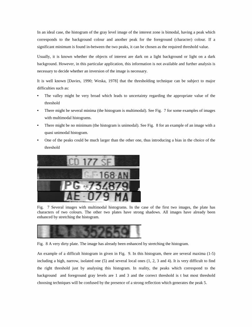
• There might be several minima (the histogram is multimodal). See Fig. 7 for some examples of images
with multimodal histograms.
• There might be no minimum (the histogram is unimodal). See Fig. 8 for an example of an image with a
quasi unimodal histogram.
• One of the peaks could be much larger than the other one, thus introducing a bias in the choice of the
threshold
Fig. 7 Several images with multimodal histograms. In the case of the first two images, the plate has characters of two colours. The other two plates have strong shadows. All images have already been enhanced by stretching the histogram.
Fig. 8 A very dirty plate. The image has already been enhanced by stretching the histogram.
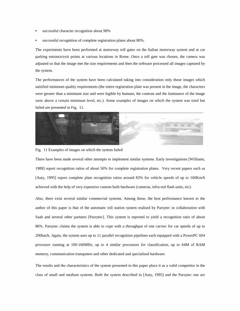
An example of a difficult histogram in given in Fig. 9. In this histogram, there are several maxima (1-5)
including a high, narrow, isolated one (5) and several local ones (1, 2, 3 and 4). It is very difficult to find
the right threshold just by analysing this histogram. In reality, the peaks which correspond to the
background and foreground gray levels are 1 and 3 and the correct threshold is t but most threshold
choosing techniques will be confused by the presence of a strong reflection which generates the peak 5.
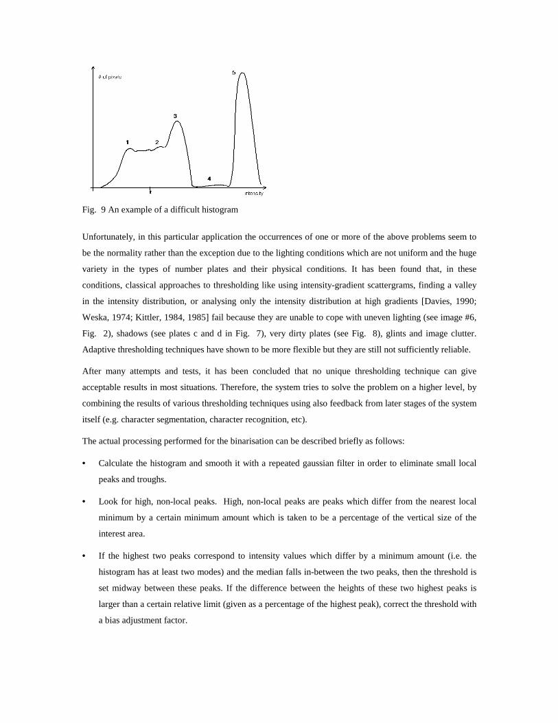
Fig. 9 An example of a difficult histogram
Unfortunately, in this particular application the occurrences of one or more of the above problems seem to
be the normality rather than the exception due to the lighting conditions which are not uniform and the huge
variety in the types of number plates and their physical conditions. It has been found that, in these
conditions, classical approaches to thresholding like using intensity-gradient scattergrams, finding a valley
in the intensity distribution, or analysing only the intensity distribution at high gradients [Davies, 1990;
Weska, 1974; Kittler, 1984, 1985] fail because they are unable to cope with uneven lighting (see image #6,
Fig. 2), shadows (see plates c and d in Fig. 7), very dirty plates (see Fig. 8), glints and image clutter.
Adaptive thresholding techniques have shown to be more flexible but they are still not sufficiently reliable.
After many attempts and tests, it has been concluded that no unique thresholding technique can give
acceptable results in most situations. Therefore, the system tries to solve the problem on a higher level, by
combining the results of various thresholding techniques using also feedback from later stages of the system
itself (e.g. character segmentation, character recognition, etc).
The actual processing performed for the binarisation can be described briefly as follows:
• Calculate the histogram and smooth it with a repeated gaussian filter in order to eliminate small local
peaks and troughs.
• Look for high, non-local peaks. High, non-local peaks are peaks which differ from the nearest local
minimum by a certain minimum amount which is taken to be a percentage of the vertical size of the
interest area.
• If the highest two peaks correspond to intensity values which differ by a minimum amount (i.e. the
histogram has at least two modes) and the median falls in-between the two peaks, then the threshold is
set midway between these peaks. If the difference between the heights of these two highest peaks is
larger than a certain relative limit (given as a percentage of the highest peak), correct the threshold with
a bias adjustment factor.

• If the highest two peaks correspond to intensity values which are closer than the minimum amount (they
belong to the same mode), or if the median does not fall in-between the two peaks, ignore the second
highest peak and try to find another one which satisfies the condition. If such a peak is found, proceed
as before. If such a peak is not found (the histogram is unimodal), scan the histogram from its peak
down until the width becomes sufficient (say 75% of the 0-255 range.; recall the fact that the histogram
has been stretched so that it covers the whole range). Take the threshold at half the width and check
whether this value is close to the median. If yes, accept this value as the threshold. If no, reject this
value and rely on the adaptive binarisation.
• In a first approximation, it is considered that there are more background pixels than character pixels in
the area of interest. Use this assumption and the position of the chosen threshold with respect to the
median to decide whether the plate contains light characters on a dark background or dark characters
on a light background. If the assumption is wrong, the recognition will fail later on. However, due to
the feedback connection implemented in the system, this failure will determine the reversal of the
colours and a second attempt at recognition.
• Perform another binarisation, adaptively. For each pixel, take into consideration a small neighbourhood
(say 4 by 4) and calculate a local range. Set the local threshold in the middle of this local range. During
this operation, also compute an average threshold and the number of black/white pixels resulted from
this adaptive binarisation. The results of the adaptive binarisation are correlated with the results of the
previous binarisation and with the feedback given by the segmentation and recognition modules.
After obtaining this binary image of the interest zone, the system performs the following steps:
• Find the number and location of the horizontal group(s) by projecting horizontally (one horizontal line
is projected to a unique value) the binary image and analysing the resulting lateral histogram.
• For each horizontal group, find the number and location of the characters by projecting vertically (one
vertical line is projected to a unique value) the binarised image of the interest zone.
• Any failure will be reported back to the previous module which can re-adjust the binarisation and the
plate segmentation.
The result of this stage is a number of character positions described by the co-ordinates and sizes of the
character boxes. These co-ordinates will be used by the system to feed the character recognition module
with the appropriate areas of the original image.
3.2.4 Character recognition
3.2.4.1 Processing
No particular assumptions have been made for the character recognition stage. This stage uses a trainable
recognition engine based on a neural network.

Each character area is divided into 8x16 smaller rectangles. For each such rectangle, an average intensity
value is calculated and this value will be fed to one input of the OCR engine.
The OCR engine was designed as an inter-changeable plug-in module. This allows the user to choose an
OCR engine which is suited to their particular application and to upgrade it easily in the future. At present,
there are several versions of this OCR engine. One of them is based on a fully connected feedforward
artificial neural network with sigmoidal activation functions. This network can be trained off -line with
various training algorithms such as error backpropagation [Rumelhart, 1986]. The standard
backpropagation network used had an architecture with 3 layers and 129, 20 and 36 neurons on the input,
hidden and output layers respectively.
An alternative OCR engine is based on the constraint based decomposition (CBD) training architecture.
CBD is a variation of the “divide and conquer” method. CBD is a constructive algorithm composed of a
weight updating rule (any algorithm able to train a single layer net), a pattern presentation algorithm and a
method for constructing the network. CBD finds an architecture able to solve the problem and trains it at the
same time. The search for the solution is performed by reducing the dimensionality of the weight space and
that of the training set. The training is performed on subnets with subgoals and the weights found in one
subgoal training will be conserved and will form a part of the final solution. The training is performed
exclusively on the simplest possible type of net: one layer, one neuron and though the resulting net is as
powerful as a multil ayer perceptron. The pattern subsets contain always n-1 correctly classified and one
misclassified pattern. The computation involved is very simple. No derivatives are calculated and no pre-
processing is needed. Redundancy elimination checks are performed and the redundant units are eliminated
during the training. Thus, the final architecture will be already pruned. The basic algorithm for a
classification task for a problem with only two classes is given in Fig. 10. More details and a comparison
between CBD and other constructive algorithms can be found in [Draghici, 1994; 1995].

The CBD algorithm
separate ( region, C1=set of patterns in C1, C2=set of patterns in C2, factor ) is
Build a subgoal S with patterns x1C1and x1C2 taken at random from C1 and C2. Delete x1C1and x1C2 from C1 and C2.
Add a hidden unit and train it to separate x1C1and x1C2. Let h be the hyperplane which separates them.
For each pattern p in C1 U C2.
Add p to the current subgoal S
Save h in h_copy
Train with the current subgoal S
if not success then
Restore h from h_copy
Remove p from S
For each pattern p in C1 U C2 /* this is the check for global redundancy */
For each old_hyperplane in old_hp_set (the set of hyperplanes already positioned)
if p is classified differently by old_hyperplane and h then
/* the hyperplanes h and old_hyperplane are not redundant */
remove old_hyperplane from old_hp_set
if old_hp_set is not empty then
/* any of the hyperplanes in old_hp_set is redundant with h; pick up any of them */
h = any of the elements of old_hp_set
Let new_factor = factor and (h,’+’ )
If the positive half-space determined by new_factor contains only patterns in the same class Cj then
Classify new_factor as Cj
else
Delete from C1 and C2 all the patterns which are not in h+. Store the result in new_C1 and new_C2.
Separate( h+, new_C1, new_C2, new_factor )
Let new_factor = factor and (h,’ -‘ )
If the negative half-space determined by new_factor contains only patterns in the same class Cj then
Classify new_factor as Cj
else
Delete from C1 and C2 all the patterns which are not in h-. Store the result in new_C1 and new_C2.
Separate( h-, new_C1, new_C2, new_factor )
Fig. 10 The constraint based decomposition algorithm.

One of the advantages of using the CBD is that the system can perform on-line training and adjust the
architecture of the neural network as required by the new information brought in by recently encountered
patterns.
3.2.4.2 The main features of the neural network based OCR engine are:
• Controlled stability-plasticity behaviour
• Controlled reliability threshold
• Both off-line and on-line learning
• Self assessment of the output reliability
• High reliability based on multiple feedback
The controlled stability-plasticity behaviour of the system is regulated through certain parameters which
instruct the system what to do in the case a character is near the validation threshold. (i.e. there are doubts
about its meaning). The user can choose a more stable behaviour when such patterns are just rejected or are
recognised with a low confidence level or a more plastic behaviour when such patterns are incorporated
through further training in the body of knowledge of the system. It is desirable to have a system which is
more plastic at the beginning and more stable afterwards.
Another important feature of the system is the fact that the reliability threshold can be controlled by the
user. Thus, it is the user who decides how to settle the inherent trade-off between reliability and recognition
rate. This trade-off is always present because, for any system and any degree of training, there will always
be characters which are close to something known but yet not quite like it. For those characters the system
has to decide whether to report them as recognised or simply reject them and it is important that this
decision be taken by the user in accordance with the requirements of the particular application.
If the optional supervision signal (see Fig. 3) is active, the system can learn on-line, adding the current
pattern (and the correct output provided by the supervisor) to the training set. If the chosen training
algorithm is the backpropagation, the recognition engine will change only the weight state. If the chosen
algorithm is CBD or other constructive algorithm, the system will be able to change both the weight state
and the architecture of the network if necessary.

The system uses a character database which is just a collection of all training patterns used during the
training. This database is stored in a file in the secondary memory of the computer system used. During the
recognition phase, the system does not access this database but uses the information conveniently stored in a
compact form in the weight state of the neural network. The database is accessed only if a new pattern is
added and the on-line trained is required.
Finally, the system gives a self-assessment of its performance for each character and each plate. This can be
used subsequently to decide how to use the results of the recognition. This self-assessment is given by the
character and plate validation modules.
The reliability is achieved by using feedback connections at various stages in the system (see Fig. 3). The
intention was to shift the important decisions regarding various aspects (like segmentation for instance)
from the low and medium level processing to a higher level. This approach was considered closer to the
processing done by the real brain which uses frequently high level information to solve lower level
segmentation or interpretation tasks5.
3.2.5 Character validation
3.2.5.1 Approach
The approach used for the validation of the recognition stage was to reject those patterns which are very
different from anything known (far in input space from any trained pattern) and those patterns which fall
near the boundary zones between different classes.
Such an approach uses the implicit assumption that the samples used in the training set are uniformly
distributed in the input space i.e. there is no large region containing valid patterns which is not represented
in the training set. In other words, it was assumed that the training set has been chosen properly and it is
representative for the problem.
5 See [Dennet, 1991] for an example in which subjects perceive a certain frequency as distinct in a white
noise if the presentation of the white noise is preceded and followed by the presentation of the given
frequency. Also, [Rumelhart, 1986] gives examples of partially occluded letters which are given different
interpretations by the brain in function of the context in which they appear.

3.2.5.2 Processing
Each time a character is submitted to the recognition engine, the result of the recognition is fed into a
validation module which has the task to decide whether the recognition is sufficiently reliable. This decision
is based on a validation threshold which is fed to the system as a parameter. Thus, the user can decide how
the system should behave. A lower validation threshold means that the system would rather reject a
character whose recognition is not sufficiently reliable. A higher validation threshold means that the
validation module would accept more easily the decisions of the recognition module. The validation
threshold in conjunction with the optional supervision signal can adjust both the reliability and the
stability-plasticity behaviour of the system to the needs of any particular application.
The validation module can signal back to the character recognition module and even further back to the
character segmentation module if the degree of confidence of the recognition is low (with respect to the
given validation threshold). If this happens, a different segmentation can be tried which can lead to a
recognition with a higher degree of confidence. These feedback connections and the iterative process they
allow can be particularly useful in those (very frequent) cases in which the plate is dirty or damaged or
when the image quality is low due to poor atmospheric conditions.
The implementation of the validation mechanism depends on the chosen OCR engine. It can also be
integrated in the OCR engine.
3.2.6 Registration number validation
After all characters segmented have been recognised, this information is fed to the registration validation
module. The role of this module is to check whether the recognised plate satisfies known a priori conditions
about the structure of the registration number (such as the number of letters, the number of digits, their
order, etc.). If the recognised plate does not satisfy these requirements, the information is passed back to the
plate segmentation module which can decide to choose an alternative segmentation and the process can be
re-iterated.
If the registration number recognised by the system satisfies the known a priori conditions, the system can
use the individual character recognition confidence values together with the registration number confidence
value to calculate a global confidence value. If the recognition is successful, the output of the system will be
the recognised registration number, a global confidence value and individual character confidence values.
These values can be taken into consideration by other applications with which the Visicar system can be
interfaced.
3.3 Other considerations related to the use in a real world application
One of the most difficult problems encountered was the image quality. A first set of causes of poor image
quality was related to various settings of the camera: the position (which introduces optical distortions),
aperture, focal length, focus, sensitivity, gain, etc. The use of a camera with various automatic controls

allowed the system to acquire a satisfactory image in most situations. However, due to the fact that the
system works in outdoor conditions and the diversity of illumination situations is huge, no image acquisition
system can give always good images. Specific problems were posed by images with specular reflections,
high gradients of luminance and contrast across the image, etc. As discussed, the histogram of such images
can be unimodal, bimodal or multimodal, with various high peaks due to reflections, etc. These phenomena
make segmentation very difficult. However, the binarisation and segmentation procedures described above
have been shown to be able to cope with most of these problems, most of the time.
Another difficulty was caused by the extremely poor quality of some plates. Such plates can have holes, can
be dirty, can have other signs attached on their surface, etc. This means that valid characters can be
connected with borders or between themselves and can be partially cover by spurious elements. Due to
these causes, any one-step segmentation method can fail. As discussed, classical methods based on
morphological analysis of the characters (dilate, erode, closure, skeleton analysis, etc.) and edge detection
[Davies, 1990; Marr, 1980] showed to be rather unreliable. The theoretical approach used to solve this
problem was a feedback link from the recognition module to the segmentation module. This makes the
recognition an iterative process in which the quality of the results (assessed through validation) can control
the segmentation. Furthermore, the validation threshold is variable and the validation results are given as a
part of the output of the system. This, together with the optional external supervision gives the system a
flexible stability-plasticity control and a variable reliability. Both elements are fundamental for a real-world
system and allows Visicar to be adjusted for the needs of a large variety of situations.
Another problem which can be extremely important for some applications is the speed of the recognition. In
tackling this problem, one can use various approaches which can range from using a more powerful
computing platform through digital hardware implementations and up to using cellular neural networks
chips. The choice depends only on the requirements of the particular application and, of course, on the
funds available.
4. Performances achieved by the system
Experiments were performed on an Intel 486/66MHz fitted with an Imaging Technology OFG VP1100-
768-E-AT frame grabber and a Comerson TC135 b/w camera. The camera features 752x582 photosensitive
elements and automatic gain and sensitivity control. Other experiments used the same software run on an
IBM RISC 6000 platform with images captured by a third party system. The performances of the camera
and the frame grabber allows the system to cope with car speeds of up to 180Km/h. A typical recognition
process for one image takes about 15s on the base platform which was a 486 PC compatible equipped with
8M of RAM memory and running at 66MHz. The speed of the recognition process increases dramatically if
a more powerful hardware platform is used.
The system has shown the following performances on average:
• successful plate location and segmentation about 99%
• successful character recognition about 98%
• successful recognition of complete registration plates about 80%.
The experiments have been performed at motorway toll gates on the Italian motorway system and at car
parking entrance/exit points at various locations in Rome. Once a toll gate was chosen, the camera was
adjusted so that the image met the size requirements and then the software processed all images captured by
the system.
The performances of the system have been calculated taking into consideration only those images which
satisfied minimum quality requirements (the entire registration plate was present in the image, the characters
were greater than a minimum size and were legible by humans, the contrast and the luminance of the image
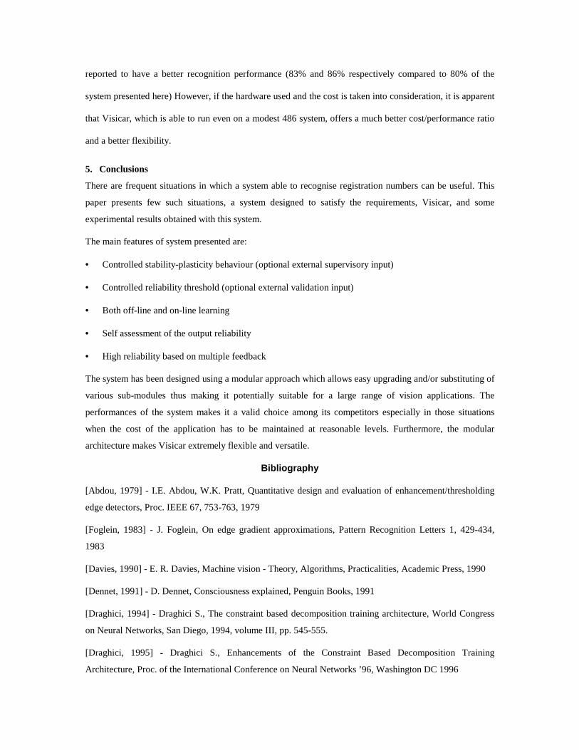
were above a certain minimum level, etc.). Some examples of images on which the system was tried but
failed are presented in Fig. 11.
Fig. 11 Examples of images on which the system failed
There have been made several other attempts to implement similar systems. Early investigations [Williams,
1989] report recognition ratios of about 50% for complete registration plates. Very recent papers such as
[Auty, 1995] report complete plate recognition ratios around 83% for vehicle speeds of up to 160Km/h
achieved with the help of very expensive custom built hardware (cameras, infra-red flash units, etc).
Also, there exist several similar commercial systems. Among those, the best performance known to the
author of this paper is that of the automatic toll station system realised by Parsytec in collaboration with
Saab and several other partners [Parsytec]. This system is reported to yield a recognition ratio of about
86%. Parsytec claims the system is able to cope with a throughput of one car/sec for car speeds of up to
200km/h. Again, the system uses up to 11 parallel recognition pipelines each equipped with a PowerPC 604
processor running at 100-166MHz, up to 4 similar processors for classification, up to 64M of RAM
memory, communication transputers and other dedicated and specialised hardware.
The results and the characteristics of the system presented in this paper place it as a valid competitor in the
class of small and medium systems. Both the system described in [Auty, 1995] and the Parsytec one are
reported to have a better recognition performance (83% and 86% respectively compared to 80% of the
system presented here) However, if the hardware used and the cost is taken into consideration, it is apparent
that Visicar, which is able to run even on a modest 486 system, offers a much better cost/performance ratio
and a better flexibilit y.
5. Conclusions
There are frequent situations in which a system able to recognise registration numbers can be useful. This
paper presents few such situations, a system designed to satisfy the requirements, Visicar, and some
experimental results obtained with this system.
The main features of system presented are:
• Controlled stabilit y-plasticity behaviour (optional external supervisory input)
• Controlled reliabilit y threshold (optional external validation input)
• Both off -line and on-line learning
• Self assessment of the output reliabilit y
• High reliabilit y based on multiple feedback
The system has been designed using a modular approach which allows easy upgrading and/or substituting of
various sub-modules thus making it potentially suitable for a large range of vision applications. The
performances of the system makes it a valid choice among its competitors especially in those situations
when the cost of the application has to be maintained at reasonable levels. Furthermore, the modular
architecture makes Visicar extremely flexible and versatile.
Bibliography
[Abdou, 1979] - I.E. Abdou, W.K. Pratt, Quantitative design and evaluation of enhancement/thresholding
edge detectors, Proc. IEEE 67, 753-763, 1979
[Foglein, 1983] - J. Foglein, On edge gradient approximations, Pattern Recognition Letters 1, 429-434,
1983
[Davies, 1990] - E. R. Davies, Machine vision - Theory, Algorithms, Practicaliti es, Academic Press, 1990
[Dennet, 1991] - D. Dennet, Consciousness explained, Penguin Books, 1991
[Draghici, 1994] - Draghici S., The constraint based decomposition training architecture, World Congress
on Neural Networks, San Diego, 1994, volume III , pp. 545-555.
[Draghici, 1995] - Draghici S., Enhancements of the Constraint Based Decomposition Training
Architecture, Proc. of the International Conference on Neural Networks ’96, Washington DC 1996

[Kittler, 1984] - J. Kittler, J. Illingworth, J. Foglein, K. Paler, An automatic thresholding algorithm and its
performance, Proc. &th Int. Conf. on Pattern Recogn., Montreal (30 July-2 August), pp. 287-289, 1984
[Kittler, 1985] - J. Kittler, J. Illingworth, J. Foglein, Threshold selection based on a simple image statistic.
Comp. Vision Graph. Image Process. 30, 125-147, 1985
[Marr, 1980] - D. Marr, E. Hildreth, Theory of edge detection, Proc.R.Soc. (London) B207, pp. 187-217
[Parsytec] - see http://www.parsytec.de/solutions/saab.html
[Rumelhart, 1986] - D.E. Rumelhart, J.L. McClelland and the PDP research group, Parallel Distributed
Processing, Explorations in the Microstructure of Cognition, The MIT Press, 1986
[Weska, 1974] - J. S. Weska, R. N. Nagel, A. Rosenfeld, A threshold selection technique, IEEE Trans.
Comput. 23, 1322-1326, 1974
[Weska, 1978] - J. S. Weska, A survey of threshold selection techniques, Comput. Graph. Image Process. 7,
259-265, 1979
[Williams, 1989] - P.G. Williams et.al., Evaluation of video recognition equipment for number plate
matching, IEE International Conference on Road Traffic Monitoring, pp. 89-93, February 1989, London