sonnox oxford inflator user guide -...
TRANSCRIPT

Contents
1 Introduction 3
2 Operation 42.1 Input Clipping . . . . . . . . . . . . . . . . . . . . . . . . . . . . . . . . . . . . 42.2 Direct and Band Splitting Modes . . . . . . . . . . . . . . . . . . . . . . . . . 52.3 Basic Loudness Enhancement Procedure . . . . . . . . . . . . . . . . . . . . 62.4 Metering and Overload Indication . . . . . . . . . . . . . . . . . . . . . . . . 72.5 Curve Modification . . . . . . . . . . . . . . . . . . . . . . . . . . . . . . . . . 72.6 Mixing with the Oxford Inflator . . . . . . . . . . . . . . . . . . . . . . . . . . 82.7 Distortion Generation . . . . . . . . . . . . . . . . . . . . . . . . . . . . . . . 9
3 DescriptionofControls 103.1 Input Section . . . . . . . . . . . . . . . . . . . . . . . . . . . . . . . . . . . . 103.2 Effect Section . . . . . . . . . . . . . . . . . . . . . . . . . . . . . . . . . . . . 113.3 Output Section . . . . . . . . . . . . . . . . . . . . . . . . . . . . . . . . . . . 12
4 Specifications 124.1 Pro Tools | HDX – Instances per chip . . . . . . . . . . . . . . . . . . . . . . . 13
5 PresetManagerToolbar 14
6 SupportedPlatforms 15
7 SystemRequirements 15
8 CopyrightandAcknowledgements 16

1 INTRODUCTION
1 Introduction
The Sonnox Oxford Inflator plug-in is designed to address the current preference toproduce the maximum apparent loudness from popular music mixes. Many processes arealready in use, which are variously reliant on compression and limiting to producemaximum modulation and try to give an impression of excitement to the sound of theprogramme. The Inflator plug-in goes further than these methods and can increase theloudness of almost any programme material, regardless of the levels of prior compressionor remaining dynamic range. It will even make full level white noise sound louder! TheInflator plug-in can also be used to create much of the warmth, character and dynamicexcitement of analogue systems within the digital domain.
The Inflator process functions by changing the relative probability of samples in theprogramme material such that there is a greater probability of larger values than theoriginal signal. The Inflator does not employ signal compression, so there is no ‘pumping’,dynamic level change, loss of presence or flattening of percussive attacks. The fulldynamic information of the music content is largely preserved despite the increase inaverage modulation density.
In addition to loudness enhancement, the Inflator can create a harmonic profile in thesignal spectrum that not only increases the apparent dynamic impact of instruments andperformances, but also provides ’warmth’ to the programme, reminiscent of good valvesystems. When used in this way, the Inflator even has the ability of good valve systems toproduce great sounding programme when significantly overdriven, and can therefore beused as an artistic enhancement tool on single performances within a mix.
www.sonnox.com 3 Gotocontents

2 OPERATION
2 Operation
2.1 InputClipping
The Inflator process develops internal signal levels thatare notionally greater than digital maximum. For instance, withthe EFFECT level at maximum and the Clip0dBr off, signal peaksabove notional digital maximum can be accommodated, andmuch of their harmonic information can be included in the outputsignal, even though the peak output level will not rise above digitalmaximum. The presence of this extra signal range is displayedon the upper sections of the INPUT level meter, and representsa range of up to +6dBr of useable overdrive before hard clippingoccurs.
The CLIP 0dBr function suppresses this extra range and restricts the Inflator process tothe normal digital maximum range. Therefore, you will note that, with CLIP 0dBr selected,the input level meter will not rise above 0dB, however much input gain is employed.Because the potential applications of this process are so varied, you are encouraged toexperiment with CLIP 0dBr on and off, to obtain the best results depending on yourintentions. Here are some general guidelines:
Generally it is better to start by selecting CLIP 0dBr on (the default) for most loudnessenhancement purposes including direct mode (non-band split) since the control of peaklevels, settings and sound character is more readily achieved when a maximum referencelevel is imposed on signals before the Inflator process.
In certain cases better results may be obtained by de-selecting any input limiting. Inparticular, the extra useable range can then be used to accommodate short-termovershoot sounds produced by compression functions, where they are generated toenhance attack and presence. Since these peaks are mostly short duration, they canoften be accommodated effectively in the overdrive ranges without excessive reduction ofsound quality or loss of average modulation. Please note that in this case it is importantto ensure that the peaks from any prior compression are not clipped between plug-ins, bymaking sure that the output signal from the compressor does not quite hit peak levelsbefore applying it to the Inflator plug-in.
When using BAND SPLIT modes for loudness enhancement, using the Inflator with CLIP0dBr off may produce a reduction in unwanted intermodulation side effects when
www.sonnox.com 4 Gotocontents

2.2 DirectandBandSplittingModes 2 OPERATION
pushing for absolute maximum loudness, regardless of possible output clipping etc.
When using direct mode (without band splitting) for distortion generation, the results willbe quite different with or without input clipping, and may produce useful artistic effects ineither circumstance. The Inflator is able to soften clips that occur, either because of theCLIP 0dBr setting, or even those that happen before its own processing in prior plug-ins.Therefore overdriving the Inflator with the CLIP 0dBr function both on and off, or evenapplying the Inflator to the output of other plug-ins driven into overdrive, can produce avast range of artistic effects. To explore the full range of possibilities, the importance ofexperimentation cannot be overstressed.
2.2 DirectandBandSplittingModes
The Inflator application can run in either direct or band splitting modes. In normaloperation, the complete frequency range of the programme material is processedsimultaneously. This is usually the best way to run the process under most conditions.One significant advantage of using this mode is that the output relative peak level will notget larger than peak level, however much Effect is applied. Therefore more overallenhancement is possible before clipping the output, and louder more powerful results arepossible. Also, when used for distortion generation, the relative phase of the distortionharmonics are better preserved when band splitting is not used, so accurate clip roundingis possible, thus producing a much more pleasing effect.
The BAND SPLIT function is offered as an additional modethat may be useful under some specific conditions. When bandsplitting is selected, the processing is split into three frequencybands to avoid intermodulation distortion between partsof the programme signal spectrum. This mode is occasionallyadvantageous when going for maximum loudness enhancementwhere there is a significant predominance of specific frequencyranges in the programme content. However it should be notedthat, depending on programme and settings, operation in thismode produces output levels that are beyond the relative input peak level. This meansthat the signal is more likely to clip at the output, which may produce an increasedharshness to the sound. If this becomes obtrusive, reducing the input or output levels toavoid clipping will obviously somewhat negate the purpose of the exercise!
www.sonnox.com 5 Gotocontents
2.3 BasicLoudnessEnhancementProcedure 2 OPERATION
2.3 BasicLoudnessEnhancementProcedure
For basic loudness enhancement, the procedure is to get the programme up to maximumnormalised level at the input (0dBr) in order to fully benefit from the Inflator process, applythe Inflator processing to get the desired effect, and then adjust the output level tomaintain desired maximum modulation.
Start with the CLIP 0dBr function selected to limit the range of the Inflator to normaldigital maximum.
Using the INPUT level control and input meter, set the level such that the red 0db overindicator flashes occasionally to indicate the presence of max peak sample values.
Set the OUTPUT level control to maximum initially, so that the input and output metershave similar readings when the music is played.
Set the CURVE control initially to its mid position (default) and deselect the BAND SPLITbutton.
Start with the EFFECT level control at 100% to obtain the maximum increase in perceivedvolume without extra peak output level.
The object of the exercise is to get the input level as high as possible without excessivedistortion or deterioration in the sound. The type of programme material and taste willdetermine the extent of the enhancement that can be achieved. If it is found that theprogramme material is not significantly degraded at normal peak input levels, further gainin loudness may be achieved by de-selecting the CLIP 0dBr button and pushing the inputlevel into the Inflator overload region.
Note:Output overloads are entirely avoided only when the Effect level control is set tomaximum position (100%).
In general the best results are most likely to be obtained by operating the Inflator EFFECTlevel at maximum, and adjusting the INPUT level and CURVE control to produce the bestsonic compromise.
Further user modifications to the Inflator process can be invoked to gain either greaterloudness or different characteristics in sonic detail, as described below.
www.sonnox.com 6 Gotocontents

2.4 MeteringandOverloadIndication 2 OPERATION
2.4 MeteringandOverloadIndication
For most workstation applications, the metering overload warning indicator is intended tocorrespond to digital maximum modulation. Different software host applications (anddifferent versions of those applications) may present varying interpretations of what thisactually represents numerically. Because the Inflator requires a very accurate andindependent internal representation of numerical maximum, differences in overloadindication may arise between the Inflator and host applications. However since theInflator overload indication is set to respond to full level samples very precisely, it willproduce legal programme if overloads are not being recorded on the plug-in GUI, even ifoverload indications are being triggered within the host mixer application.
Further user modifications to the Inflator process can be invoked to either gain greaterloudness or different characteristics in sonic detail, as described below.
2.5 CurveModification
The CURVE modification control subtly affects the characteristic of the Inflator process toaffect both the perceived loudness and tonal character of the signal.
With the CURVE control set at its minimum position (-50), the Inflator produces the mostsubtle changes to the sound. Overall loudness enhancement is minimal but significantharmonic content is added to produce a richer overall sonic character. When applied tocomposite mixes, the predominantly loud parts of the mix will apparently be accentuatedover the background and reverberant parts of the programme, producing the effect ofdynamic expansion (without a time constant).
This setting is particularly useful when treating drums and percussion instruments, whenthe impression of dynamic presence needs to be enhanced, or the contribution to the mixneeds to be ‘tightened up’. This kind of setting is also useful when used on singleinstruments (such as acoustic guitars) where a softening of percussive aspects or ‘highs’is needed without loss of apparent dynamic range.
Settings of the curve control between -50 and around zero have varying degrees of thisbehaviour and style of overall impression, but with increasing ‘fatness’ and volume as thecurve control is advanced.
The CURVE control at its mid position (default zero) produces a special behaviour, whichin many respects may give the best results in most situations. The overall loudness of thesignal is considerably enhanced whilst retaining good dynamic balance between loud and
www.sonnox.com 7 Gotocontents
2.6 MixingwiththeOxfordInflator 2 OPERATION
soft portions of the programme, with a minimum of intermodulation effect. The soniccharacter has a much enhanced warmth and harmonic detail, adding presence andtexture to instruments, especially in the low frequency register. The highs and peaks inthe programme are softened in character without loss of apparent presence, attack or‘bite’. Occasional peak programme overloads are softened and become less intrusive andcan therefore be tolerated more readily. With the CURVE control in this position, theInflator produces a gentle and forgiving behaviour, which has many aspects in commonwith the character of good valve amplification systems, including a natural tolerance tooverload conditions. For example, when used in direct mode (band splitting de-selected)with CLIP 0dBr selected and the EFFECT level set to 100%, even clipped programmesignals can be rendered musical in nature. This can be used to produce artistic distortioneffects on single instruments within a mix or produce dynamic ‘breaking up’ effects, muchlike that possible with valve amplifiers. Or you may just want to obtain an overall valve-likecharacter and warmth to the sound.
At positions between 0 and +50 the CURVE control provides increasing ‘fatness’ andvolume enhancement at the partial expense of dynamic precision, producing the loudestand most exciting effects at +50. In this position the sound becomes most powerful witha harmonic profile reminiscent of systems under great stress and running to their verylimits. The music will take on an ‘in your face’ quality, creating the maximum excitementyet fine detail and subtleties within the mix will be retained. Despite rendering the signalsignificantly louder, the impression of considerable dynamic range is retained even thoughthe output peak level range is largely unchanged. The low level and background parts ofthe mix will become enhanced and more audible and extreme LF contributions frominstruments such as basses will stand out more readily on smaller reproduction systems.Programme treated with this process will produce louder sounds on all reproductionequipment, and in particular it will produce unsuspected volume and power from smalldomestic and portable systems.
2.6 MixingwiththeOxfordInflator
The Inflator can bring added benefit to the mixing process if it is inserted on the mainoutput buss throughout the mixing session. In this case it is possible to use the valve-likeharmonic characteristics and the extra overload area to greater advantage, because theseform part of the sound of the mix as it is built up. In some respects this process isreminiscent of analogue mixing where line-up operating levels may be breached bytransients without actual signal clipping, and the sonic character of the signal chain is to
www.sonnox.com 8 Gotocontents

2.7 DistortionGeneration 2 OPERATION
some degree dependent on balance and instrument contribution levels.
It is suggested that, in this case, the best initial settings are with the Inflator set to directmode (ie. not band split), with the CURVE control set to the mid position (0) and withCLIP 0dBr de-selected. The input gain should be set somewhat above unity (+6dB) toallow the mixer to operate without clipping overshoots prior to the Inflator, and the outputshould be set to max (0db) to provide full output modulation. These settings will establisha virtual operating level at –6dBr within the mixing environment, with a possible overloadarea provided by the Inflator process for short-term level peaks to be accommodatedwithout clipping. The Inflator input and output meters can then be used as main outputbuss level reference monitors during the mix session.
2.7 DistortionGeneration
For distortion generation, it is best to proceed initially with the EFFECT level set tomaximum so that the nature of any distortion can be assessed. The idea is to increase theinput level with the Inflator fully operational, and the OUTPUT control reduced somewhatto avoid output clipping, whilst listening to the results with various degrees of deliberateand significant signal overdrive. The CURVE control and CLIP 0dBr selector will bothaffect the sound of the results, depending on the programme material being processed.However, the best results are most likely to be obtained with the CURVE control set to itsmid (0) position, as this produces the least higher order harmonic levels and mostresembles the dynamics behaviour of valve systems. In general, it is best to avoidband-splitting mode if aiming for natural warmth and valve overdrive sounds. Inputclipping will dramatically change the nature of the distortion in overdrive situations andyou are encouraged to experiment with the CLIP 0dBr selector both on and off, andchanging the order of plug-ins in the signal path.
www.sonnox.com 9 Gotocontents
3 DESCRIPTION OF CONTROLS
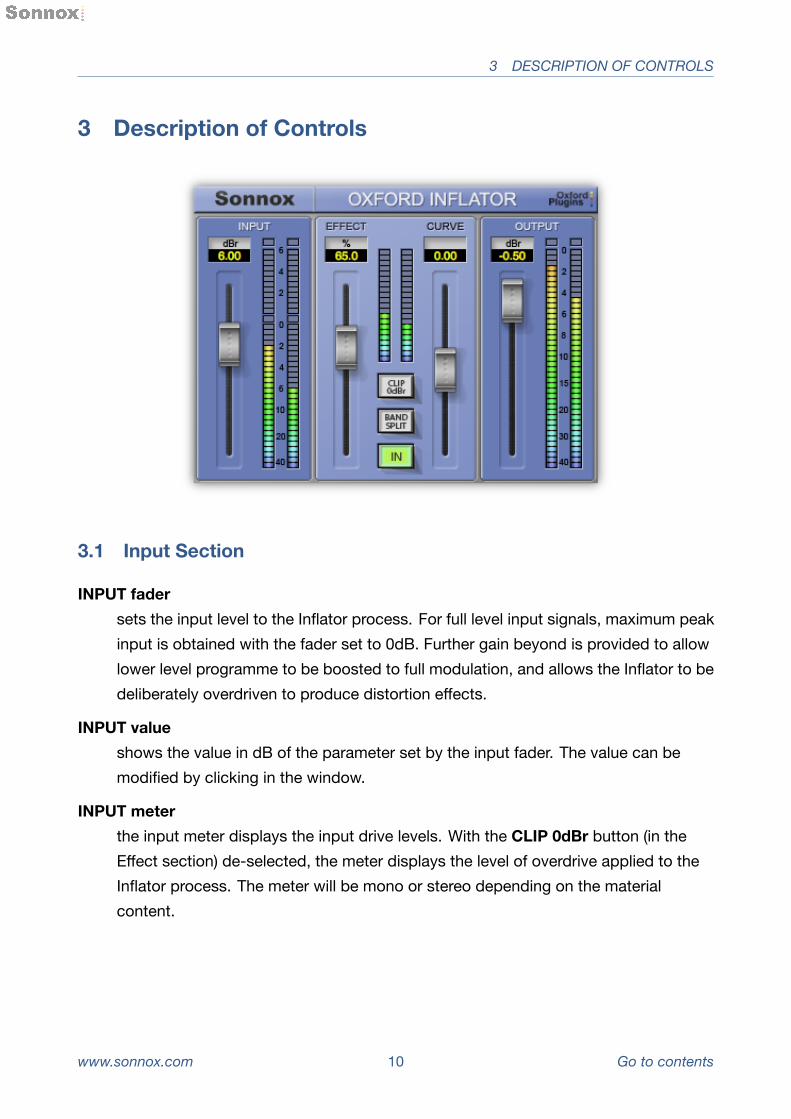
3 DescriptionofControls
3.1 InputSection
INPUT fadersets the input level to the Inflator process. For full level input signals, maximum peakinput is obtained with the fader set to 0dB. Further gain beyond is provided to allowlower level programme to be boosted to full modulation, and allows the Inflator to bedeliberately overdriven to produce distortion effects.
INPUT valueshows the value in dB of the parameter set by the input fader. The value can bemodified by clicking in the window.
INPUT meterthe input meter displays the input drive levels. With the CLIP 0dBr button (in theEffect section) de-selected, the meter displays the level of overdrive applied to theInflator process. The meter will be mono or stereo depending on the materialcontent.
www.sonnox.com 10 Gotocontents

3.2 EffectSection 3 DESCRIPTION OF CONTROLS
3.2 EffectSection
EFFECT fadersets the amount of the overall Inflator effect that is applied to the programme, from0% to 100%.
EFFECT valueshows the value in dB of the parameter set by the EFFECT fader. The value can bemodified by clicking in the window.
EFFECT meterindicates the degree of average signal modification in real time, depending onprogramme type and Inflator settings.
CURVE fadermodifies the processing characteristics and sonic effect of the Inflator.
CURVE valueshows the value in dB of the parameter set by the CURVE fader. The value can beedited by clicking in the window.
CLIP 0dBrwhen this button is selected, internal processing levels are restricted to theequivalent of normal digital maximum. When de-selected, internal processing maydevelop and process signals beyond the equivalent of digital maximum.
BAND SPLITselects processing on the direct full band signal or invokes a band splitting functionthat processes the signal separately in the LF, MF and HF spectral regions.
IN This switches the Inflator process in and out for comparison purposes.
www.sonnox.com 11 Gotocontents

3.3 OutputSection 4 SPECIFICATIONS
3.3 OutputSection
OUTPUT fadersets the output level to allow adjustment of the signal level after processing.
OUTPUT valuehows the value in dB of the parameter set by the output fader. The value can bemodified by clicking in the window.
OUTPUT meterthe output meter indicates 0.5 dB per segment for the top 10dB of dynamic range,and a smaller scale thereafter. The meter will be mono or stereo depending onprogramme content.
SonnoxMenuButton
Clicking the Sonnox button produces a drop-down options menu (see right).
ClipLightscan be set to hold for 2 seconds, 5 seconds, or Indefinitely.
EnableSonnoxToolbardisplays or hides the Preset Manager Toolbar.
ShowPresetNamePathdisplays or hides the preset name path in the Preset Manager Toolbar.
Aboutdisplays the date, version and build number of the plug-in.
4 Specifications
www.sonnox.com 12 Gotocontents

4.1 ProTools|HDX –Instancesperchip 4 SPECIFICATIONS
4.1 ProTools|HDX –Instancesperchip
Mode 48kHz 96kHz 192kHz
BandSplit Mono 26 12 6
Stereo 13 6 3
SinglePath(Direct) Mono 81 39 18
Stereo 41 20 9
www.sonnox.com 13 Gotocontents
5 PRESET MANAGER TOOLBAR
5 PresetManagerToolbar
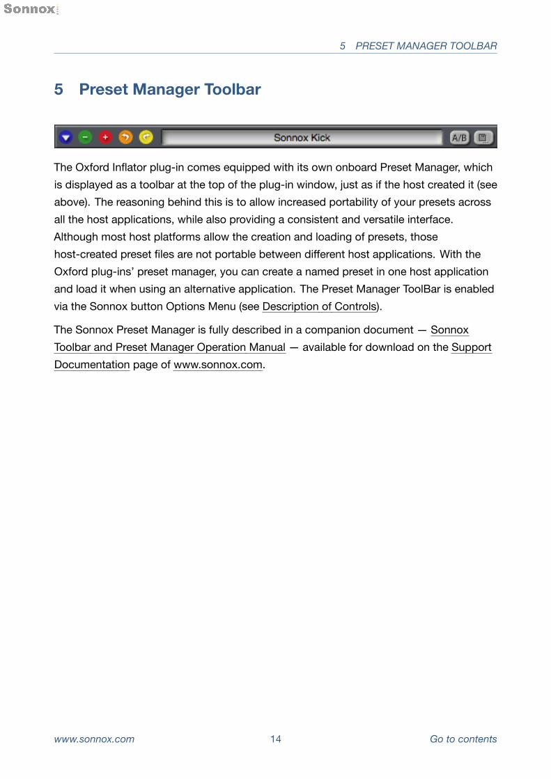
The Oxford Inflator plug-in comes equipped with its own onboard Preset Manager, whichis displayed as a toolbar at the top of the plug-in window, just as if the host created it (seeabove). The reasoning behind this is to allow increased portability of your presets acrossall the host applications, while also providing a consistent and versatile interface.Although most host platforms allow the creation and loading of presets, thosehost-created preset files are not portable between different host applications. With theOxford plug-ins’ preset manager, you can create a named preset in one host applicationand load it when using an alternative application. The Preset Manager ToolBar is enabledvia the Sonnox button Options Menu (see Description of Controls).
The Sonnox Preset Manager is fully described in a companion document — SonnoxToolbar and Preset Manager Operation Manual — available for download on the SupportDocumentation page of www.sonnox.com.
www.sonnox.com 14 Gotocontents

7 SYSTEM REQUIREMENTS
6 SupportedPlatforms
• Avid Pro Tools (AAX Native and DSP 32/64-bit)
• VST hosts (32/64-bit)
• AU hosts (32/64-bit)
• Mac Intel OSX 10.6 or higher
• Windows 7 and 8 (32/64-bit)
7 SystemRequirements
For latest System requirements, please visit www.sonnox.com.
Allversions
• Free iLok account
• Appropriate product licence
• iLok2
ProTools
• Approved Digidesign/Avid CPU and hardware configuration
• Pro Tools 10.3.5 (Native or HD), or higher
VST Native
• VST compliant host application (e.g. Cubase, Nuendo, etc.)
AudioUnits
• Approved Apple CPU and OSX 10.6 or higher
• Audio Unit Host application (e.g. Logic, Digital Performer, etc.)
www.sonnox.com 15 Gotocontents

8 COPYRIGHT AND ACKNOWLEDGEMENTS
8 CopyrightandAcknowledgements
Trademarks and content copyright © 2007-present Sonnox® Ltd. All rights reserved.
Sonnox® and the five dots logo are registered trademarks of Sonnox Ltd.
This product is manufactured and supplied by Sonnox Ltd. This product is protected byone or more European and/or US patents.
DIGIDESIGN, AVID and PRO TOOLS are trademarks or registered trademarks of AvidTechnology Inc.
VST is a trademark of Steinberg AG.
All other product and Company names are trademarks or registered trademarks of theirrespective holders.
www.sonnox.com 16 Gotocontents