sonic boom calculations for the n+2 configuration · conventional cae solution with grid ... 0 50...
TRANSCRIPT

Sonic Boom Calculations for the N+2 Configuration!
Mark D. Sanetrik NASA Langley Research Center \
Presented at ASE Summit NASA Ames Research Center
April 14, 2015
https://ntrs.nasa.gov/search.jsp?R=20160007032 2018-07-06T23:54:24+00:00Z

Outline
• Introduction • Requirements for Sonic Boom Calculations • Challenges of Sonic Boom Calculations • Sample Solutions • Sonic Boom Results
– Effect of Grid Resolution – Effect of Domain Extent – Effect of Near-Field Pressure Extraction Location – Effect of Static Aeroelastic Deflections – Effect of Engines
• Concluding Remarks and Future Work

Introduction
• Low sonic boom flight a major requirement for N+2 Program
• Extensive work done to optimize sonic boom signature
• Optimization done on a rigid structure
• Structure will deflect aeroelastically under aerodynamic loads
• How will static aeroelastic deflections change the sonic boom signature?

Requirements for Sonic Boom Calculations
• Conventional Static Aeroelastic domain is rectangular
• Body is defined at 0o angle of attack
• Same grid can be used for multiple flow conditions
• Sonic Boom domain must be shock aligned
• Conical-shaped domain with angle of cone dictated by Mach angle
• Body must be rotated to proper angle of attack
• Separate grid for each flow condition

CAE Computational Domain

CAE Computational Domain Detail
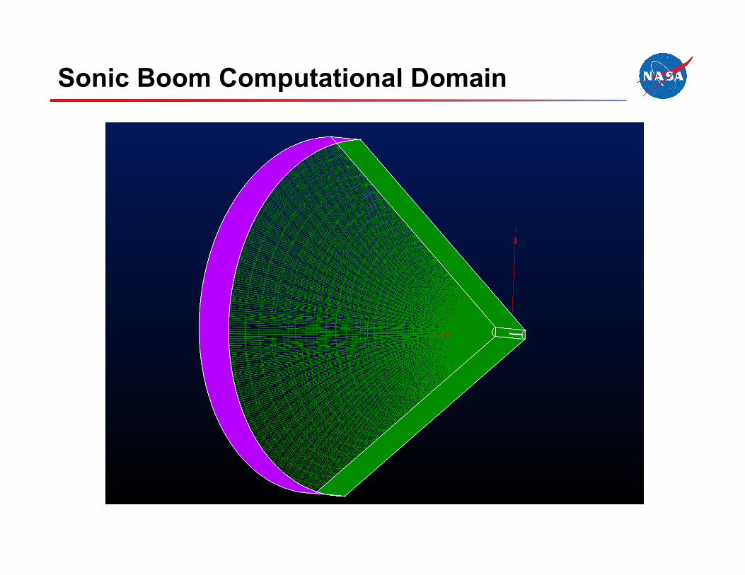
Sonic Boom Computational Domain

Sonic Boom Computational Domain

Challenges of Sonic Boom Calculations
• Separate grid for every flow condition
• Extremely fine near-field grid required
• Where to extract pressure signature?
– Too close and the pressure signature not fully developed
– Too far away and the pressure signature is dissipated
– Current practice is 3 body lengths
• Use of external program to propagate shock to ground level (sBOOM)
• Interpretation of ground signatures

Conventional CAE Solution Inviscid, No Engines, Mach = 1.70, α = 2.25ο
11.8 MGP, CL = 0.14343, CD = 0.09220

Conventional CAE Solution with Grid Inviscid, No Engines, Mach = 1.70, α = 2.25ο
11.8 MGP, CL = 0.14343, CD = 0.09220

Sonic Boom Coarse Solution Inviscid, No Engines, Mach = 1.70, α = 2.25ο
15.9 MGP, CL = 0.14342, CD = 0.09252

Sonic Boom Coarse Solution with Grid Inviscid, No Engines, Mach = 1.70, α = 2.25ο
115.9 MGP, CL = 0.14342, CD = 0.09252

Sonic Boom Medium Solution Inviscid, No Engines, Mach = 1.70, α = 2.25ο
46.5 MGP, CL = 0.14343, CD = 0.09251

Sonic Boom Medium Solution with Grid Inviscid, No Engines, Mach = 1.70, α = 2.25ο
46.5 MGP, CL = 0.14343, CD = 0.09251

Sonic Boom Fine Solution Inviscid, No Engines, Mach = 1.70, α = 2.25ο
89.9 MGP, CL = 0.14342, CD = 0.09256

Sonic Boom Fine Solution with Grid Inviscid, No Engines, Mach = 1.70, α = 2.25ο
89.9 MGP, CL = 0.14342, CD = 0.09256

Sonic Boom Grid Resolution Study
5000 6000 7000 8000 9000x (in.)
-0.03
-0.02
-0.01
0
0.01
0.02
0.03
Coarse GridMedium GridFine Grid
Near-field Pressure SignatureNo Engines, Undeformed, Mach = 1.7, Alpha = 2.25

Sonic Boom Grid Resolution Study (cont.)
0 50 100 150 200 250 300time, ms
-1
-0.5
0
0.5
1
1.5
Ove
rpre
ssur
e, p
sf
Coarse GridMedium GridFine Grid
Ground Level Boom SignatureNo Engines, Undeformed, Mach = 1.7, Alpha = 2.25

Sonic Boom Domain Size Study
5000 6000 7000 8000 9000 10000 11000x, inches
-0.03
-0.02
-0.01
0
0.01
0.02
0.03
dp/p
Coarse Grid Short DomainCoarse Grid Long DomainMedium Grid Short DomainMedium Grid Long Domain
Near-field Pressure SignatureNo Engines, Undeformed, Mach = 1.7, Alpha = 2.25

Sonic Boom Domain Size Study (cont.)
0 50 100 150 200 250 300time, ms
-1
-0.5
0
0.5
1
1.5
Ove
rpre
ssur
e, p
sf
Coarse Grid Short DomainCoarse Grid Long DomainMedium Grid Short DomainMedium Grid Long Domain
Ground Level Boom SignatureNo Engines, Undeformed, Mach = 1.7, Alpha = 2.25

Sonic Boom Extraction Position Study
2000 4000 6000 8000 10000x (in)
-0.04
-0.03
-0.02
-0.01
0
0.01
0.02
dp/p
1.00 Body Length1.38 Body Lengths2.00 Body Lengths3.00 Body Lengths
Near-field Pressure SignatureNo Engines, Meduim Grid, Undeformed, Mach = 1.7, Alpha = 2.25

Sonic Boom Extraction Position Study (cont.)
0 50 100 150 200 250 300Time (ms)
-1.0
-0.5
0.0
0.5
1.0
1.5
Ove
rpre
ssur
e (p
sf)
1.00 Body Length1.38 Body Lengths2.00 Boby Lengths3.00 Body Lengths
Ground Level Boom SignatureNo Engines, Medium Grid, Undeformed, Mach = 1.7, Alpa 2.25

Sonic Boom Effect of Deflections Study
5000 6000 7000 8000 9000x (in.)
-0.03
-0.02
-0.01
0
0.01
0.02
0.03
dp/p
UndeformedDeformed
Near-field Pressure SignatureNo Engines, Medium Grid, Mach = 1.7, Alpha = 2.25

Sonic Boom Effect of Deflections Study (cont.)
0 100 200 300Time (ms)
-1.0
-0.5
0.0
0.5
1.0
1.5
Ove
rpre
ssur
e (p
sf)
UndeformedDeformed
Ground Level Boom SignatureMedium Grid, No Engines, Mach = 1.7, Alpa 2.25

Sonic Boom Effect of Engines Study
5000 6000 7000 8000 9000x (in.)
-0.03
-0.02
-0.01
0
0.01
0.02
0.03
No EnginesEngines
Near-field Pressure SignatureMeduim Grid, Undeformed, Mach = 1.7, Alpha = 2.25

Sonic Boom Effect of Engines Study (cont.)
0 50 100 150 200 250 300Time (ms)
-1.5
-1.0
-0.5
0.0
0.5
1.0
1.5
Ove
rpre
ssur
e (p
sf)
No EnginesEngines
Ground Level Boom SignatureMedium Grid, Undeformed, Mach = 1.7, Alpa 2.25

Concluding Remarks
• Sonic boom signatures have been computed for the N+2 configuration • Still a work in progress; much learning to be done • Major questions to be answered
– Exactly what is the configuration are we analyzing? – What is the best procedure for static aeroelastic computations?
• Future Work – Additional computations with engines – More realistic engines? – Viscous Calculations
• A good start has been made in the investigation of the aeroelastic effects on the sonic boom signature
