sonia parvanova • georgi vasilev • petia dineva • frank wuttke manolis gd, beskos de (1987)...
TRANSCRIPT
Numerical Analysis and Modeling of 2D Soil-Structure Interaction Problems by Hybrid BEM-FEM Technique
Dynamic Analysis, Testing and Design of Infrastructure to
Environmental Loads - November 11-13, 2014, Thessaloniki
1
Numerical Analysis and Modeling of 2D Soil-Structure Interaction Problems by Hybrid BEM-FEM Technique
• Sonia Parvanova
• Georgi Vasilev
• Petia Dineva
• Frank Wuttke
Numerical Analysis and Modeling of 2D Soil-Structure Interaction Problems by Hybrid BEM-FEM Technique
Dynamic Analysis, Testing and Design of Infrastructure to
Environmental Loads - November 11-13, 2014, Thessaloniki
2
OUTLINE:
BEM-FEM coupling in frequency domain Algorithm
Numerical results
BEM-FEM coupling in time domain Standard convolution formula
Lubich convolution quadrature method
Validation tests
Numerical Analysis and Modeling of 2D Soil-Structure Interaction Problems by Hybrid BEM-FEM Technique
Dynamic Analysis, Testing and Design of Infrastructure to
Environmental Loads - November 11-13, 2014, Thessaloniki
3 3
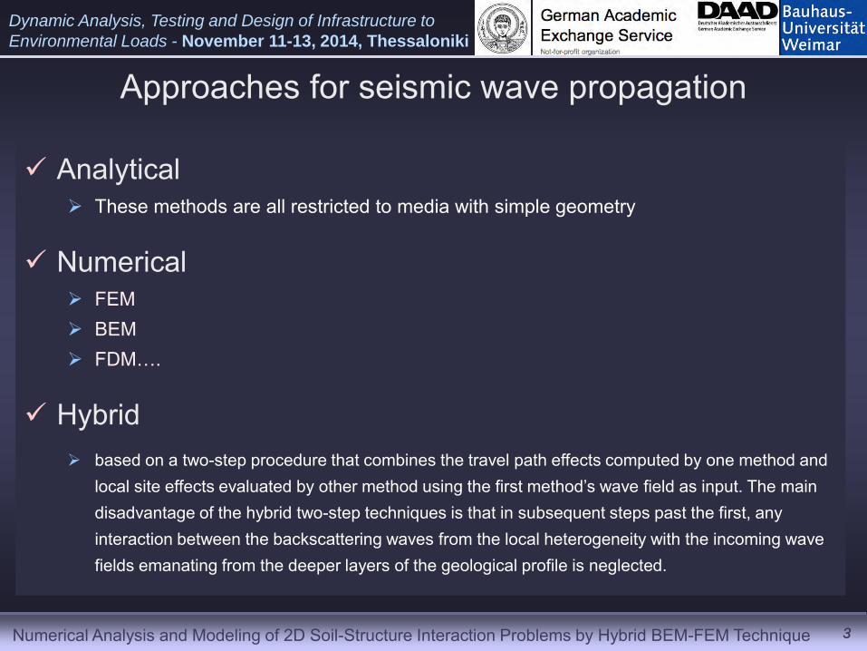
Approaches for seismic wave propagation
Analytical These methods are all restricted to media with simple geometry
Numerical FEM BEM FDM….
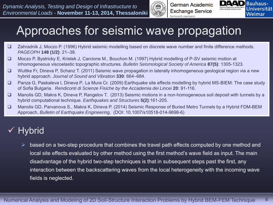
Hybrid based on a two-step procedure that combines the travel path effects computed by one method and
local site effects evaluated by other method using the first method’s wave field as input. The main disadvantage of the hybrid two-step techniques is that in subsequent steps past the first, any interaction between the backscattering waves from the local heterogeneity with the incoming wave fields emanating from the deeper layers of the geological profile is neglected.
Numerical Analysis and Modeling of 2D Soil-Structure Interaction Problems by Hybrid BEM-FEM Technique
Dynamic Analysis, Testing and Design of Infrastructure to
Environmental Loads - November 11-13, 2014, Thessaloniki
4 4
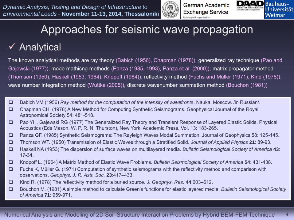
Analytical
Babich VM (1956) Ray method for the computation of the intensity of wavefronts. Nauka, Moscow. /in Russian/. Chapman CH. (1978) A New Method for Computing Synthetic Seismograms. Geophysical Journal of the Royal
Astronomical Society 54: 481-518. Pao YH, Gajewski RG (1977) The Generalized Ray Theory and Transient Response of Layered Elastic Solids. Physical
Acoustics (Eds Mason, W. P, R. N. Thurston), New York, Academic Press, Vol. 13: 183-265. Panza GF. (1985) Synthetic Seismograms: The Rayleigh Waves Modal Summation. Journal of Geophysics 58: 125-145. Thomson WT. (1950) Transmission of Elastic Waves through a Stratified Solid. Journal of Applied Physics 21: 89-93. Haskell NA (1953) The dispersion of surface waves on multilayered media. Bulletin Seismological Society of America 43:
17-34. Knopoff L. (1964) A Matrix Method of Elastic Wave Problems. Bulletin Seismological Society of America 54: 431-438. Fuchs K, Müller G. (1971) Computation of synthetic seismograms with the reflectivity method and comparison with
observations. Geophys. J. R. Astr. Soc. 23:417–433. Kind R. (1978) The reflectivity method for a buried source. J. Geophys. Res. 44:603–612. Bouchon M. (1981) A simple method to calculate Green's functions for elastic layered media. Bulletin Seismological Society
of America 71: 959-971.
Approaches for seismic wave propagation
The known analytical methods are ray theory (Babich (1956), Chapman (1978)), generalized ray technique (Pao and Gajewski (1977)), mode mathicng methods (Panza (1985, 1993), Panza et al. (2000)), matrix propagator method (Thomson (1950), Haskell (1953, 1964), Knopoff (1964)), reflectivity method (Fuchs and Müller (1971), Kind (1978)), wave number integration method (Wuttke (2005)), discrete wavenumber summation method (Bouchon (1981))

Numerical Analysis and Modeling of 2D Soil-Structure Interaction Problems by Hybrid BEM-FEM Technique
Dynamic Analysis, Testing and Design of Infrastructure to
Environmental Loads - November 11-13, 2014, Thessaloniki
5 5
Numerical FEM BEM FDM….
The numerical techniques as finite difference method (Moczo (1989)), finite element method (Gatmiri et al. (2008), Gatmiti and Arson (2008)), boundary integral equation method (Manolis and Beskos (1987), Dominguez (1993), Bouchon and Sánchez-Sesma (2007), Dineva et al. (1996)) are suitable for studying complex structures, but usually they require much CPU time and memory
Moczo P. (1989) Finite-difference technique for SH waves in 2-D media using irregular grids: application to the seismic response problem. Geophys.J. Int. 99: 321-329.
Gatmiri B, Arson C, Nguyen KV. (2008) Seismic site effects by an optimized 2D BE/FE method. I. Theory, numerical optimization and application to topographical irregularities. Soil Dynamics and
Earthquake Engineering 28 (8): 632–645. Manolis GD, Beskos DE (1987) Boundary Element Methods in Elastodynamics. Unwin and Allen,
London. Dominguez J. (1993) Boundary elements in dynamics. Computational Mechanics Publications,
Southampton. Bouchon M, Sánchez-Sesma FJ. (2007) Boundary integral equations and boundary elements
methods in elastodynamics. Adv. Geophys. 48: 157-189. Dineva P, Borejko P, Hadjikov L, Zigler F. (1996) Transient elastic waves in a half-space:
comparison of the DBIE - method with the method of generalized ray. Acta Mechanica 115: 203-211.
Parvanova, S., Dineva P., G. Manolis, Fr. Wuttke. (2014a) Seismic response of lined tunnels in the half-plane with surface topography, Bulletin of Earthquake Engineering 12: 981-1005.
Parvanova S, Dineva P, Manolis G, Kochev P. (2014b) Dynamic Response of a Solid with Multiple Inclusions under Anti-plane Strain Conditions by the BEM. Computers and Structures
139:65-83. Parvanova S, Dineva P, Manolis G (2014c) Elastic wave fields in a half-plane with free Surface
relief, tunnels and multiple buried inclusions. Acta Mechanica 225(7): 1843-1865.
Approaches for seismic wave propagation
Numerical Analysis and Modeling of 2D Soil-Structure Interaction Problems by Hybrid BEM-FEM Technique
Dynamic Analysis, Testing and Design of Infrastructure to
Environmental Loads - November 11-13, 2014, Thessaloniki
6 6
Approaches for seismic wave propagation
Hybrid based on a two-step procedure that combines the travel path effects computed by one method and
local site effects evaluated by other method using the first method’s wave field as input. The main disadvantage of the hybrid two-step techniques is that in subsequent steps past the first, any interaction between the backscattering waves from the local heterogeneity with the incoming wave fields is neglected.
Zahradnik J, Moczo P. (1996) Hybrid seismic modelling based on discrete wave number and finite difference methods. PAGEOPH 148 (1/2): 21–38.
Moczo P, Bystricky E, Kristek J, Carcione M., Bouchon M. (1997) Hybrid modelling of P-SV seismic motion at inhomogeneous viscoelastic topographic structures. Bulletin Seismological Society of America 87(5): 1305-1323.
Wuttke Fr, Dineva P, Schanz T. (2011) Seismic wave propagation in laterally inhomogeneous geological region via a new hybrid approach. Journal of Sound and Vibration 330: 664–684.
Panza G, Paskaleva I, Dineva P, La Mura Cr. (2009) Earthquake site effects modelling by hybrid MS-BIEM: The case study of Sofia Bulgaria. Rendiconti di Scienze Fisiche by the Accademia dei Lincei 20: 91-116.
Manolis GD, Makra K, Dineva P, Rangelov T. (2013) Seismic motions in a non-homogeneous soil deposit with tunnels by a hybrid computational technique. Earthquakes and Structures 5(2):161-205.
Manolis GD, Parvanova S., Makra K, Dineva P. (2014) Seismic Response of Buried Metro Tunnels by a Hybrid FDM-BEM Approach, Bulletin of Earthquake Engineering, (DOI: 10.1007/s10518-014-9698-6)
Numerical Analysis and Modeling of 2D Soil-Structure Interaction Problems by Hybrid BEM-FEM Technique
Dynamic Analysis, Testing and Design of Infrastructure to
Environmental Loads - November 11-13, 2014, Thessaloniki
7
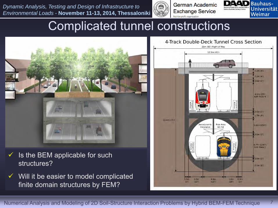
Complicated tunnel constructions
Is the BEM applicable for such structures?
Will it be easier to model complicated finite domain structures by FEM?
Numerical Analysis and Modeling of 2D Soil-Structure Interaction Problems by Hybrid BEM-FEM Technique
Dynamic Analysis, Testing and Design of Infrastructure to
Environmental Loads - November 11-13, 2014, Thessaloniki
8
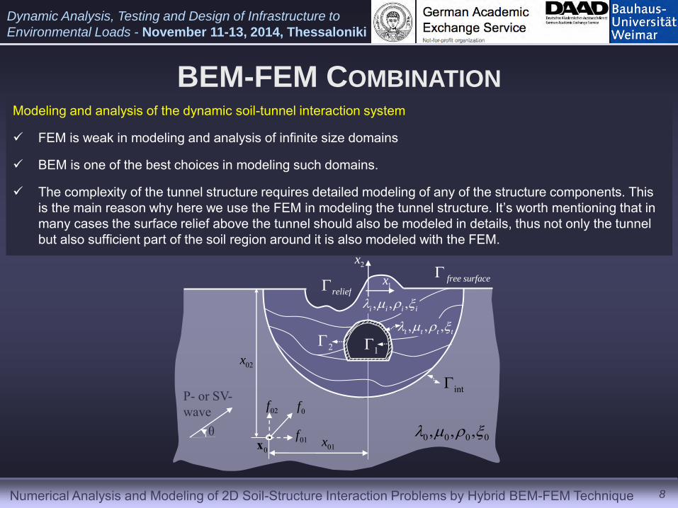
Modeling and analysis of the dynamic soil-tunnel interaction system
FEM is weak in modeling and analysis of infinite size domains
BEM is one of the best choices in modeling such domains.
The complexity of the tunnel structure requires detailed modeling of any of the structure components. This is the main reason why here we use the FEM in modeling the tunnel structure. It’s worth mentioning that in many cases the surface relief above the tunnel should also be modeled in details, thus not only the tunnel but also sufficient part of the soil region around it is also modeled with the FEM.
, , ,t t t t
P- or SV- wave
θ 0x
0f02f
01f01x
02x
0 0 0 0, , ,
12
, , ,i i i i
int
free surface1x
2x
relief
BEM-FEM COMBINATION
Numerical Analysis and Modeling of 2D Soil-Structure Interaction Problems by Hybrid BEM-FEM Technique
Dynamic Analysis, Testing and Design of Infrastructure to
Environmental Loads - November 11-13, 2014, Thessaloniki
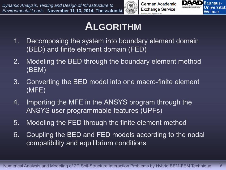
ALGORITHM 1. Decomposing the system into boundary element domain
(BED) and finite element domain (FED)
2. Modeling the BED through the boundary element method (BEM)
3. Converting the BED model into one macro-finite element (MFE)
4. Importing the MFE in the ANSYS program through the ANSYS user programmable features (UPFs)
5. Modeling the FED through the finite element method
6. Coupling the BED and FED models according to the nodal compatibility and equilibrium conditions
9
Numerical Analysis and Modeling of 2D Soil-Structure Interaction Problems by Hybrid BEM-FEM Technique
Dynamic Analysis, Testing and Design of Infrastructure to
Environmental Loads - November 11-13, 2014, Thessaloniki
10
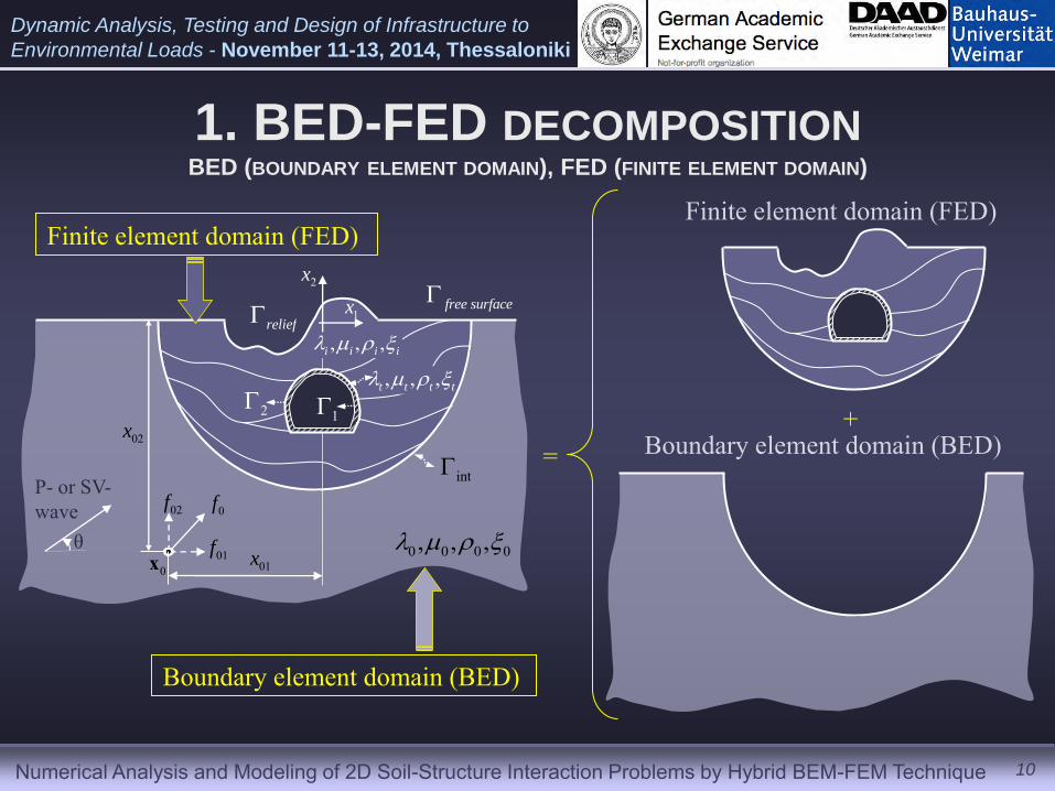
1. BED-FED DECOMPOSITION BED (BOUNDARY ELEMENT DOMAIN), FED (FINITE ELEMENT DOMAIN)
, , ,t t t t
P- or SV- wave
θ 0x
0f02f
01f01x
02x
0 0 0 0, , ,
12
, , ,i i i i
int
free surface1x
2x
relief
Finite element domain (FED)
Boundary element domain (BED)
Finite element domain (FED)
Boundary element domain (BED) = +
Numerical Analysis and Modeling of 2D Soil-Structure Interaction Problems by Hybrid BEM-FEM Technique
Dynamic Analysis, Testing and Design of Infrastructure to
Environmental Loads - November 11-13, 2014, Thessaloniki
11
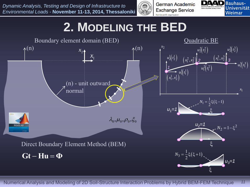
Boundary element domain (BED)
2. MODELING THE BED
1x2x
0 0 0 0, , ,
(n) - unit outward normal
(n) (n)
Direct Boundary Element Method (BEM)
1
2 3 1 12 2u t
1 11 1u t
2 22 2u t 3 3
2 2u t
3 31 1u t
2 21 1u t
1 11 2,x x
2 21 2,x x 3 3
1 2,x x
1x
2x
11 12
N
22 1N
31 12
N
u1=1
u2=1
u3=1
Quadratic BE
Gt Hu Φ

Numerical Analysis and Modeling of 2D Soil-Structure Interaction Problems by Hybrid BEM-FEM Technique
Dynamic Analysis, Testing and Design of Infrastructure to
Environmental Loads - November 11-13, 2014, Thessaloniki
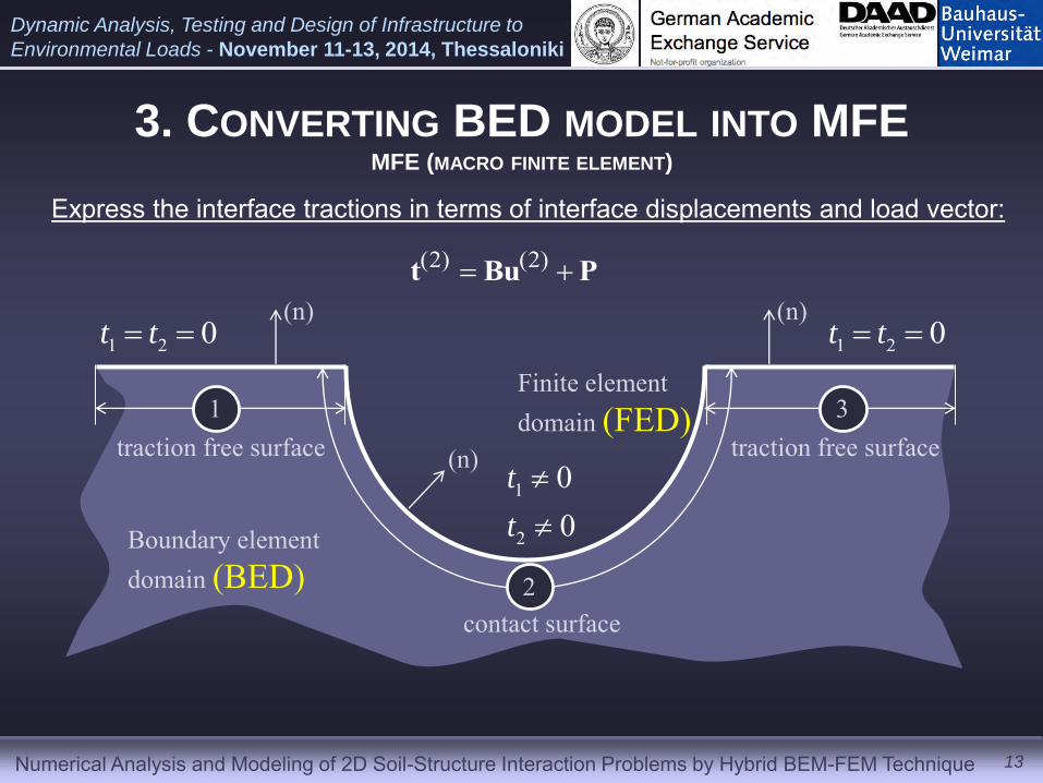
3. CONVERTING BED MODEL INTO MFE MFE (MACRO FINITE ELEMENT)
3.1. DOFs condensation at the BED-FED contact nodes
12
1
2
3 traction free surface traction free surface
contact surface
(n)
(n) (n)
1
2
00
t
t
1 2 0t t 1 2 0t t
Finite element domain (FED)
Boundary element domain (BED)
Numerical Analysis and Modeling of 2D Soil-Structure Interaction Problems by Hybrid BEM-FEM Technique
Dynamic Analysis, Testing and Design of Infrastructure to
Environmental Loads - November 11-13, 2014, Thessaloniki
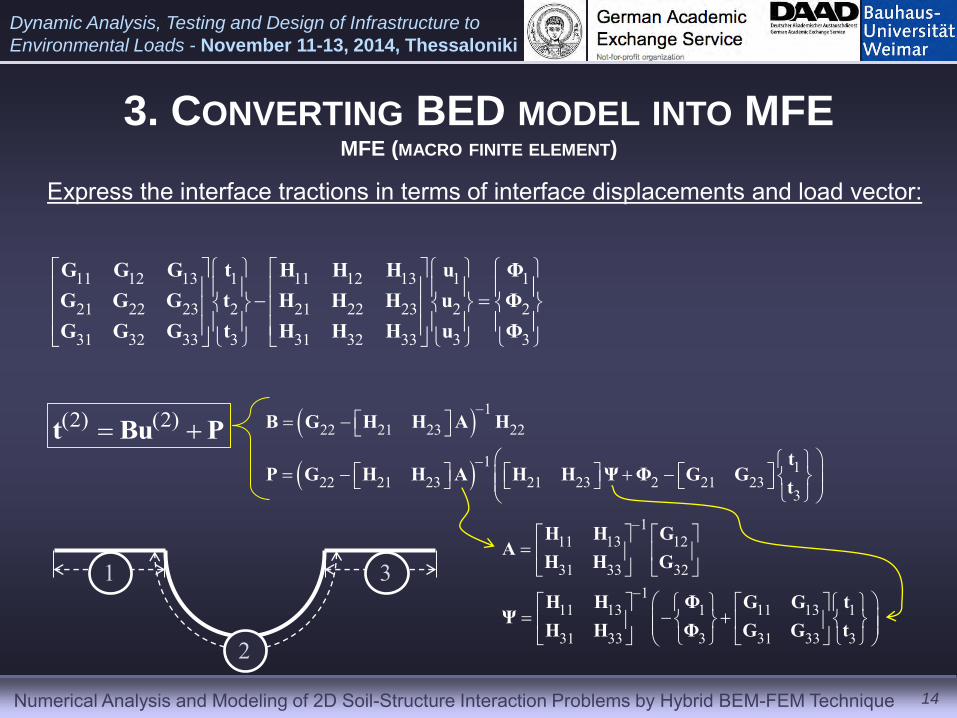
3. CONVERTING BED MODEL INTO MFE MFE (MACRO FINITE ELEMENT)
Express the interface tractions in terms of interface displacements and load vector:
13
traction free surface traction free surface
contact surface
(n)
(n) (n)
1
2
00
t
t
1 2 0t t 1 2 0t t
Finite element domain (FED)
Boundary element domain (BED)
1
2
3
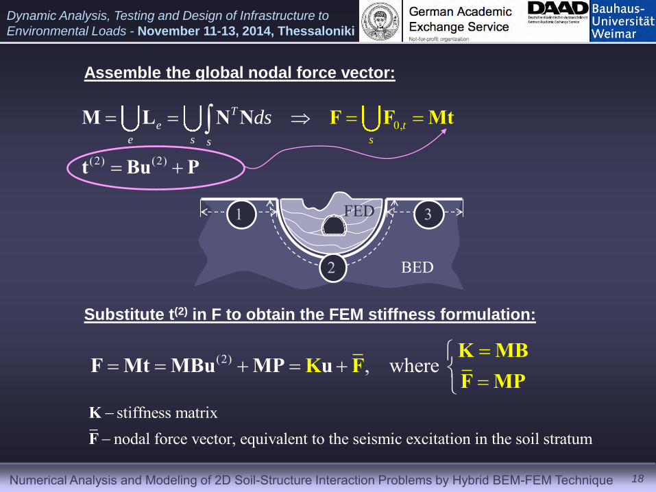
(2) (2) t Bu P
Numerical Analysis and Modeling of 2D Soil-Structure Interaction Problems by Hybrid BEM-FEM Technique
Dynamic Analysis, Testing and Design of Infrastructure to
Environmental Loads - November 11-13, 2014, Thessaloniki
3. CONVERTING BED MODEL INTO MFE MFE (MACRO FINITE ELEMENT)
Express the interface tractions in terms of interface displacements and load vector:
14
(2) (2) t Bu P
122 21 23 22
1 122 21 23 21 23 2 21 23
3
B G H H A H
tP G H H A H H Ψ Φ G G
t
11 12 13 1 11 12 13 1 1
21 22 23 2 21 22 23 2 2
31 32 33 3 31 32 33 3 3
G G G t H H H u ΦG G G t H H H u ΦG G G t H H H u Φ
111 13 12
31 33 321
11 13 1 11 13 1
31 33 3 31 33 3
H H GA
H H G
H H Φ G G tΨ
H H Φ G G t
1 3
2
Numerical Analysis and Modeling of 2D Soil-Structure Interaction Problems by Hybrid BEM-FEM Technique
Dynamic Analysis, Testing and Design of Infrastructure to
Environmental Loads - November 11-13, 2014, Thessaloniki
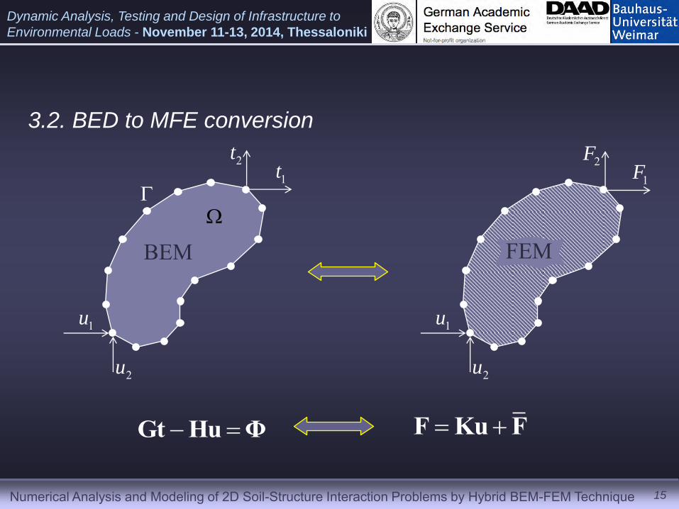
3.2. BED to MFE conversion
Gt Hu Φ F Ku F
15
FEM BEM
2t
1t
1u
2u
2F
1F
1u
2u
Numerical Analysis and Modeling of 2D Soil-Structure Interaction Problems by Hybrid BEM-FEM Technique
Dynamic Analysis, Testing and Design of Infrastructure to
Environmental Loads - November 11-13, 2014, Thessaloniki
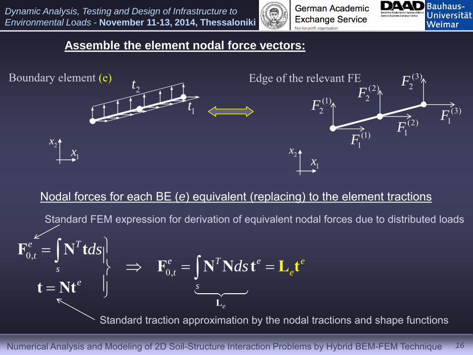
Assemble the element nodal force vectors:
16
1t
2tBoundary element (e)
(1)2F
(1)1F
(2)2F
(2)1F
(3)2F
(3)1F
Edge of the relevant FE
1x2x
1x2x
0,
0,
e
e T
te T e
s te s
e
e
dsds
L
F N tF N N
t Ntt
tL
Nodal forces for each BE (e) equivalent (replacing) to the element tractions
Standard traction approximation by the nodal tractions and shape functions
Standard FEM expression for derivation of equivalent nodal forces due to distributed loads
Numerical Analysis and Modeling of 2D Soil-Structure Interaction Problems by Hybrid BEM-FEM Technique
Dynamic Analysis, Testing and Design of Infrastructure to
Environmental Loads - November 11-13, 2014, Thessaloniki
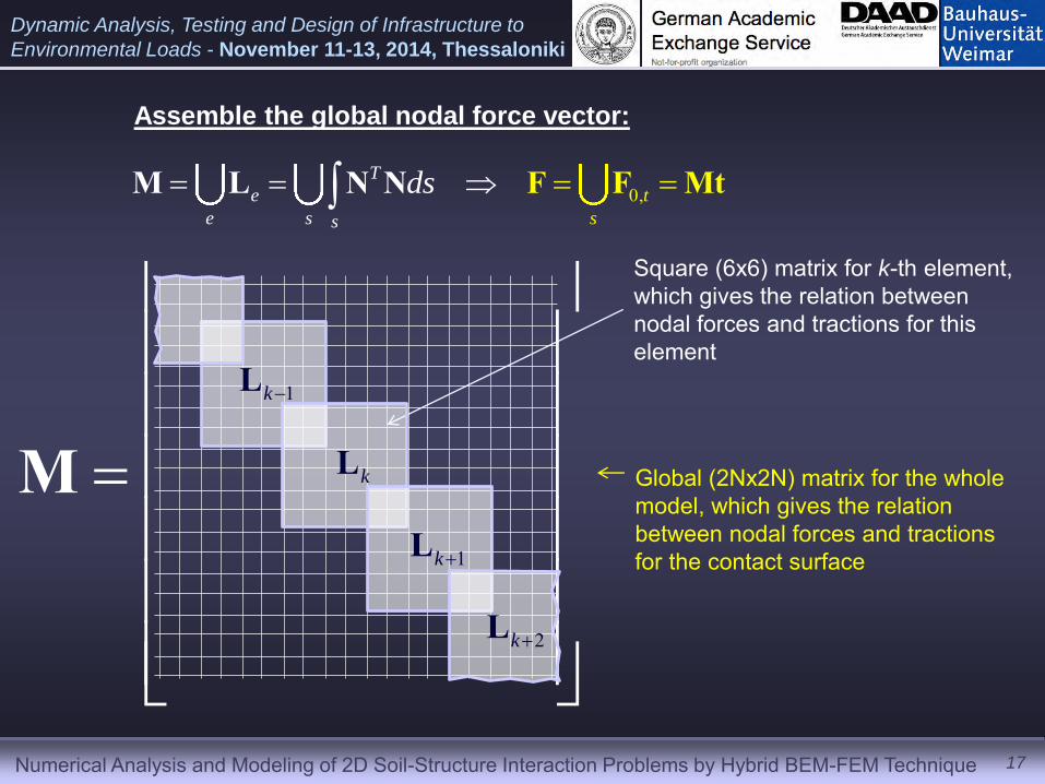
Assemble the global nodal force vector:
0,T
e
e s
t
s s
ds FN FM L N Mt
Square (6x6) matrix for k-th element, which gives the relation between nodal forces and tractions for this element
Global (2Nx2N) matrix for the whole model, which gives the relation between nodal forces and tractions for the contact surface
17
M1kL
kL
1kL
2kL
Numerical Analysis and Modeling of 2D Soil-Structure Interaction Problems by Hybrid BEM-FEM Technique
Dynamic Analysis, Testing and Design of Infrastructure to
Environmental Loads - November 11-13, 2014, Thessaloniki
0
(2) (2
,
)
T
e
e s s
t
s
ds
M L N N
t B
F F M
u P
t
(2) , where
K MBK FF Mt MB
Fu
MPMP u
Substitute t(2) in F to obtain the FEM stiffness formulation:
stiffness matrixnodal force vector, equivalent to the seismic excitation in the soil stratum
KF
18
Assemble the global nodal force vector:
1 3
2 BED
FED
Numerical Analysis and Modeling of 2D Soil-Structure Interaction Problems by Hybrid BEM-FEM Technique
Dynamic Analysis, Testing and Design of Infrastructure to
Environmental Loads - November 11-13, 2014, Thessaloniki
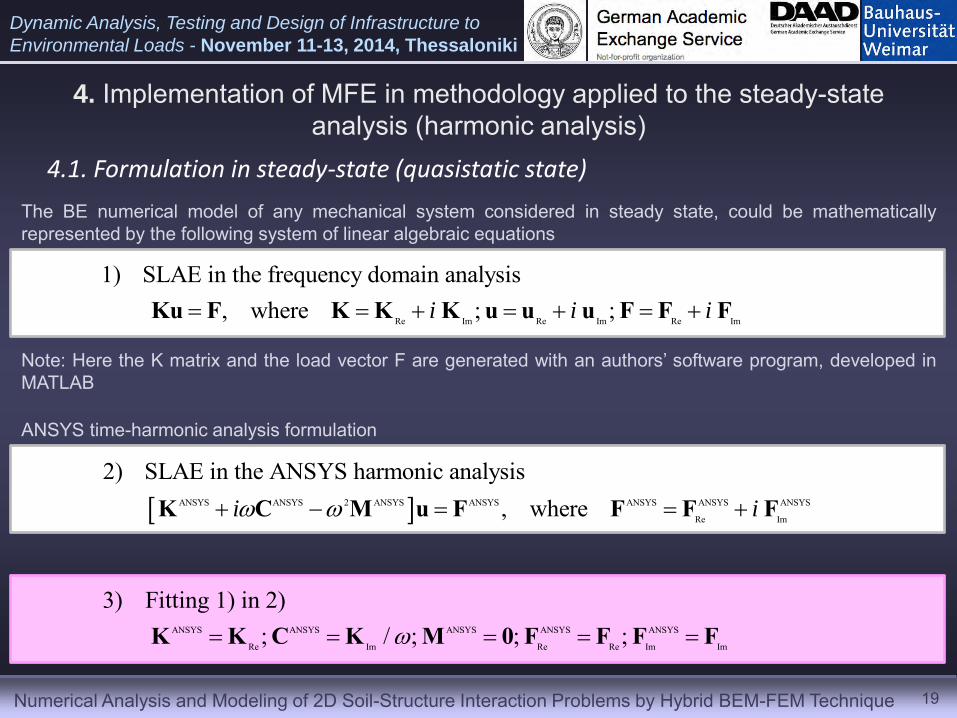
4. Implementation of MFE in methodology applied to the steady-state analysis (harmonic analysis)
4.1. Formulation in steady-state (quasistatic state)
19
The BE numerical model of any mechanical system considered in steady state, could be mathematically represented by the following system of linear algebraic equations
ANSYS time-harmonic analysis formulation
Re Im Re Im Re Im
1) SLAE in the frequency domain analysis, where ; ;i i i Ku F K K K u u u F F F
ANSYS ANSYS 2 ANSYS ANSYS ANSYS ANSYS ANSYS
Re Im
2) SLAE in the ANSYS harmonic analysis, wherei i K C M u F F F F
ANSYS ANSYS ANSYS ANSYS ANSYS
Re Im Re Re Im Im
3) Fitting 1) in 2); / ; ; ; K K C K M 0 F F F F
Note: Here the K matrix and the load vector F are generated with an authors’ software program, developed in MATLAB
Numerical Analysis and Modeling of 2D Soil-Structure Interaction Problems by Hybrid BEM-FEM Technique
Dynamic Analysis, Testing and Design of Infrastructure to
Environmental Loads - November 11-13, 2014, Thessaloniki
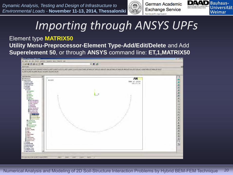
Importing through ANSYS UPFs
20
Element type MATRIX50
Utility Menu-Preprocessor-Element Type-Add/Edit/Delete and Add Superelement 50, or through ANSYS command line: ET,1,MATRIX50
Numerical Analysis and Modeling of 2D Soil-Structure Interaction Problems by Hybrid BEM-FEM Technique
Dynamic Analysis, Testing and Design of Infrastructure to
Environmental Loads - November 11-13, 2014, Thessaloniki
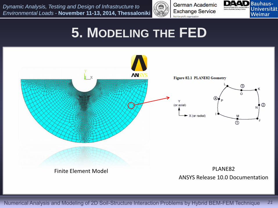
5. MODELING THE FED
Finite Element Model PLANE82
ANSYS Release 10.0 Documentation
21
Numerical Analysis and Modeling of 2D Soil-Structure Interaction Problems by Hybrid BEM-FEM Technique
Dynamic Analysis, Testing and Design of Infrastructure to
Environmental Loads - November 11-13, 2014, Thessaloniki
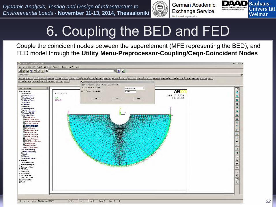
6. Coupling the BED and FED Couple the coincident nodes between the superelement (MFE representing the BED), and
FED model through the Utility Menu-Preprocessor-Coupling/Ceqn-Coincident Nodes
22
Numerical Analysis and Modeling of 2D Soil-Structure Interaction Problems by Hybrid BEM-FEM Technique
Dynamic Analysis, Testing and Design of Infrastructure to
Environmental Loads - November 11-13, 2014, Thessaloniki
Free surface Γff
P-, SV- wave
h x1
x2
φ a
Free surface Γff
P-, SV- wave
h x1
x2
φ a
23
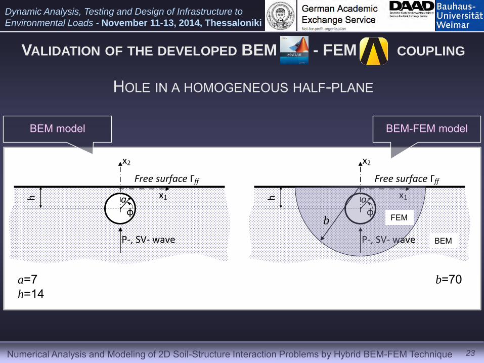
VALIDATION OF THE DEVELOPED BEM - FEM COUPLING
HOLE IN A HOMOGENEOUS HALF-PLANE
BEM model BEM-FEM model
a=7 h=14
b=70
b BEM
FEM
Numerical Analysis and Modeling of 2D Soil-Structure Interaction Problems by Hybrid BEM-FEM Technique
Dynamic Analysis, Testing and Design of Infrastructure to
Environmental Loads - November 11-13, 2014, Thessaloniki
24
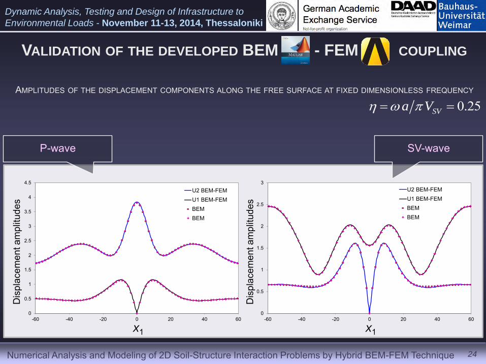
VALIDATION OF THE DEVELOPED BEM - FEM COUPLING
P-wave SV-wave
AMPLITUDES OF THE DISPLACEMENT COMPONENTS ALONG THE FREE SURFACE AT FIXED DIMENSIONLESS FREQUENCY
0.25SVa V
0
0.5
1
1.5
2
2.5
3
3.5
4
4.5
-60 -40 -20 0 20 40 60
U2 BEM-FEMU1 BEM-FEMBEMBEM
0
0.5
1
1.5
2
2.5
3
-60 -40 -20 0 20 40 60
U2 BEM-FEMU1 BEM-FEMBEMBEM
Dis
plac
emen
t am
plitu
des
Dis
plac
emen
t am
plitu
des
x1 x1
Numerical Analysis and Modeling of 2D Soil-Structure Interaction Problems by Hybrid BEM-FEM Technique
Dynamic Analysis, Testing and Design of Infrastructure to
Environmental Loads - November 11-13, 2014, Thessaloniki
0
0.5
1
1.5
2
2.5
3
-60 -40 -20 0 20 40 60
U2 BEM-FEMU1 BEM-FEMBEMBEM
0
0.5
1
1.5
2
2.5
-60 -40 -20 0 20 40 60
U2 BEM-FEMU1 BEM-FEMBEMBEM
25
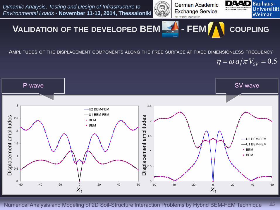
VALIDATION OF THE DEVELOPED BEM - FEM COUPLING
P-wave SV-wave
AMPLITUDES OF THE DISPLACEMENT COMPONENTS ALONG THE FREE SURFACE AT FIXED DIMENSIONLESS FREQUENCY
Dis
plac
emen
t am
plitu
des
Dis
plac
emen
t am
plitu
des
x1 x1
0.5SVa V

Numerical Analysis and Modeling of 2D Soil-Structure Interaction Problems by Hybrid BEM-FEM Technique
Dynamic Analysis, Testing and Design of Infrastructure to
Environmental Loads - November 11-13, 2014, Thessaloniki
26
NUMERICAL SIMULATION OF A PRACTICAL PROBLEM
7.4 4.77
5 4.
9
1.7
0.4
0.3
0.15
0.3
0.15 0.40
(a)
a=7
x1
x2
70
µ 1, ν1, ρ1, ζ1
µ 2, ν2, ρ2, ζ2
µ 3, ν3, ρ3, ζ3
µ 4, ν4, ρ4, ζ4
µ5, ν5, ρ5, ζ5
(b)
Tunnel construction Soil deposit
Numerical Analysis and Modeling of 2D Soil-Structure Interaction Problems by Hybrid BEM-FEM Technique
Dynamic Analysis, Testing and Design of Infrastructure to
Environmental Loads - November 11-13, 2014, Thessaloniki
27
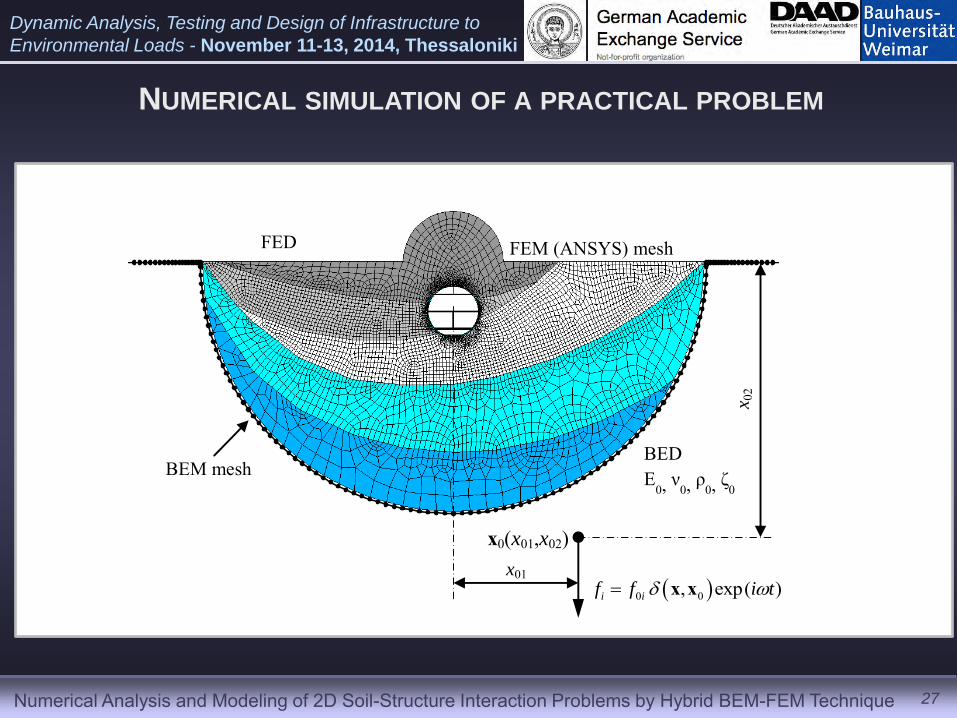
NUMERICAL SIMULATION OF A PRACTICAL PROBLEM
0 0, exp( )i if f i t x x
x0(x01,x02)
BED E
0, ν0, ρ0, ζ0
FEM (ANSYS) mesh FED
BEM mesh
x01
x 02
Numerical Analysis and Modeling of 2D Soil-Structure Interaction Problems by Hybrid BEM-FEM Technique
Dynamic Analysis, Testing and Design of Infrastructure to
Environmental Loads - November 11-13, 2014, Thessaloniki
0
1
2
3
4
5
6
7
8
9
0.05 0.15 0.25 0.35 0.45
|u2|-point 1
|u2|-point 2
|u2|-point 3
|u2|-point 4
0
0.5
1
1.5
2
2.5
3
0.1 0.15 0.2 0.25 0.3 0.35 0.4 0.45 0.5
|u2|-point 1
|u2|-point 2
|u2|-point 3
|u2|-point 4
SVa V
Dis
pla
cem
ent
amp
litu
des
|u
2|
0
0.5
1
1.5
2
2.5
3
3.5
0 0.1 0.2 0.3 0.4 0.5
|u2|-point 1
|u2|-point 2
|u2|-point 3
|u2|-point 4
Dis
pla
cem
ent
amp
litu
des
|u
2|
SVa V
0
1
2
3
4
5
6
7
8
0 0.1 0.2 0.3 0.4 0.5
|u1|-point 1
|u1|-point 2
|u1|-point 3
|u1|-point 4
Dis
pla
cem
ent
amp
litu
des
|u
1|
SVa V
1 2 3
4
a) b)
c) d)
Dis
pla
cem
ent
amp
litu
des
|u
2|
SVa V
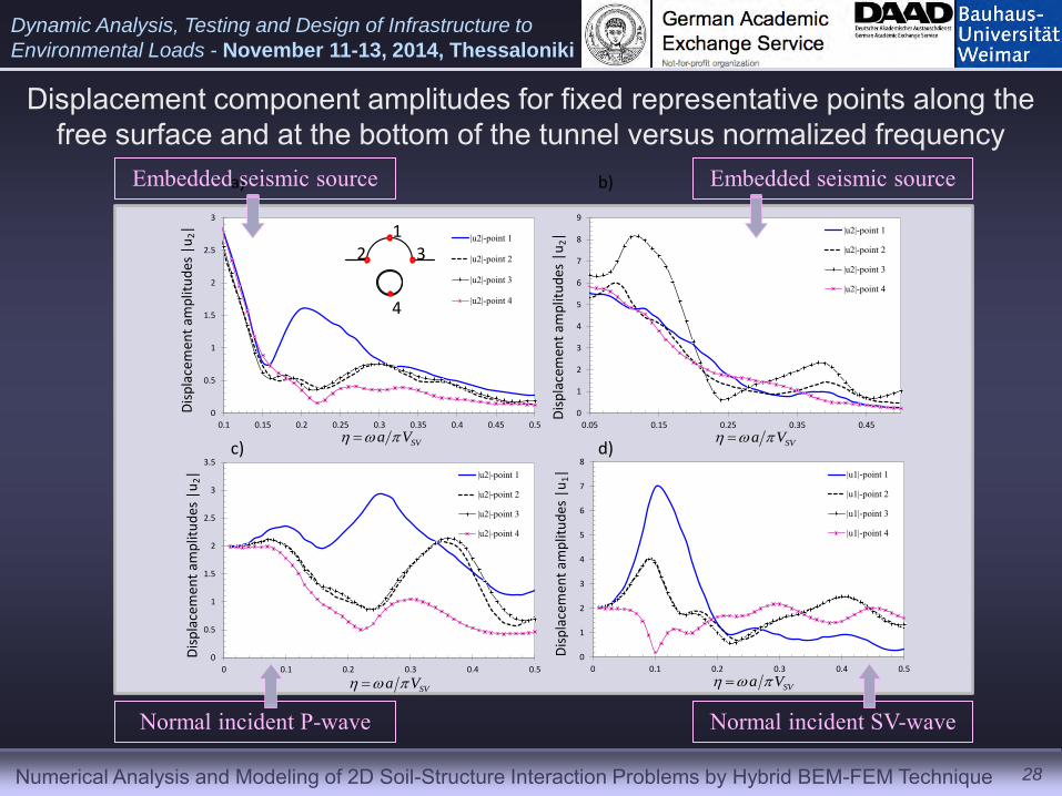
Displacement component amplitudes for fixed representative points along the free surface and at the bottom of the tunnel versus normalized frequency
28
Embedded seismic source
Normal incident SV-wave
Embedded seismic source
Normal incident P-wave
Numerical Analysis and Modeling of 2D Soil-Structure Interaction Problems by Hybrid BEM-FEM Technique
Dynamic Analysis, Testing and Design of Infrastructure to
Environmental Loads - November 11-13, 2014, Thessaloniki
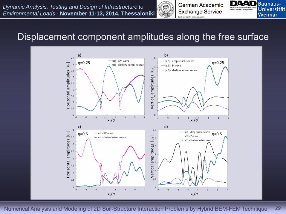
Displacement component amplitudes along the free surface
29
0
0.5
1
1.5
2
2.5
3
3.5
-7 -5 -3 -1 1 3 5 7
|u2| - deep seism. source|u2| - P-wave|u2| - shallow seism. source
0
0.5
1
1.5
2
2.5
3
3.5
4
-7 -5 -3 -1 1 3 5 7
|u1| - SV-wave
|u1| - shallow seism. source
0
1
2
3
4
5
6
-7 -5 -3 -1 1 3 5 7
|u2| - deep seism. source|u2| - P-wave|u2| - shallow seism. source
0
0.5
1
1.5
2
2.5
3
3.5
4
4.5
-7 -5 -3 -1 1 3 5 7
|u1| - SV-wave|u1| - shallow seism. source
a) b)
c) d)
η=0.25 η=0.25
x1/a x1/a
Ho
rizo
nta
l am
plit
ud
es |
u1|
Ver
tica
l am
plit
ud
es |
u2|
x1/a x1/a
η=0.5 η=0.5
Ho
rizo
nta
l am
plit
ud
es |
u1|
Ver
tica
l am
plit
ud
es |
u2|
Numerical Analysis and Modeling of 2D Soil-Structure Interaction Problems by Hybrid BEM-FEM Technique
Dynamic Analysis, Testing and Design of Infrastructure to
Environmental Loads - November 11-13, 2014, Thessaloniki
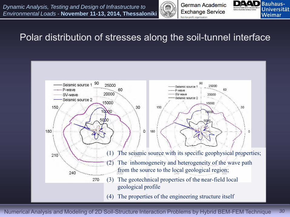
Polar distribution of stresses along the soil-tunnel interface
30
(1) The seismic source with its specific geophysical properties; (2) The inhomogeneity and heterogeneity of the wave path
from the source to the local geological region; (3) The geotechnical properties of the near-field local
geological profile (4) The properties of the engineering structure itself
Numerical Analysis and Modeling of 2D Soil-Structure Interaction Problems by Hybrid BEM-FEM Technique
Dynamic Analysis, Testing and Design of Infrastructure to
Environmental Loads - November 11-13, 2014, Thessaloniki
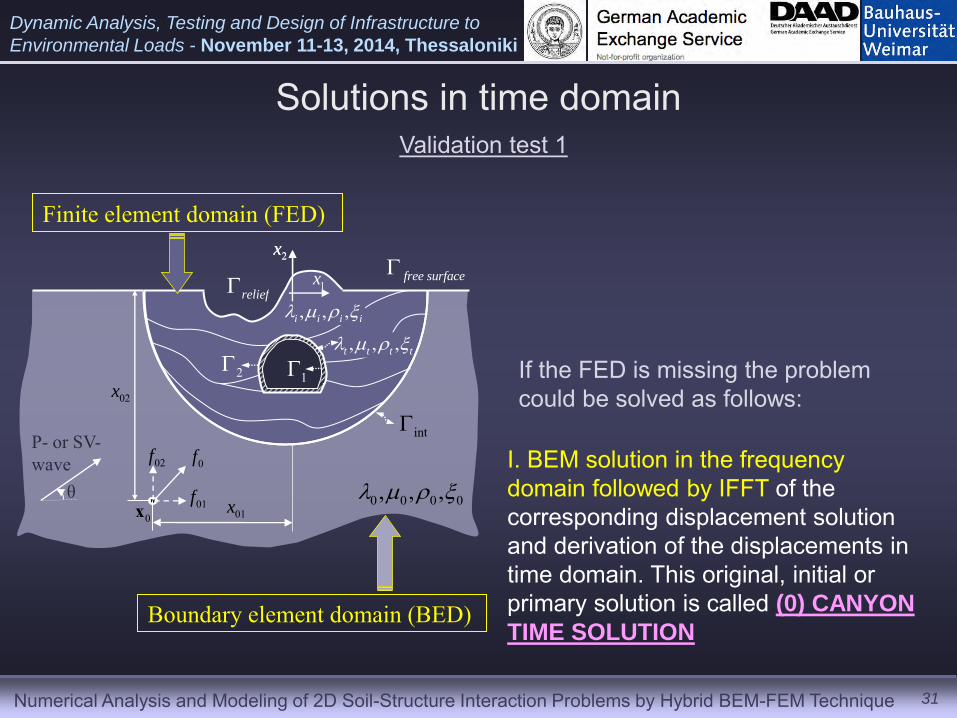
Solutions in time domain
31
P- or SV- wave
θ 0x
0f02f
01f01x 0 0 0 0, , ,
free surface
Boundary element domain (BED)
1x
2x
Validation test 1
If the FED is missing the problem could be solved as follows:
I. BEM solution in the frequency domain followed by IFFT of the corresponding displacement solution and derivation of the displacements in time domain. This original, initial or primary solution is called (0) CANYON
TIME SOLUTION
Finite element domain (FED)
02x
, , ,t t t t
12
, , ,i i i i
int
relief 1x
2x
Numerical Analysis and Modeling of 2D Soil-Structure Interaction Problems by Hybrid BEM-FEM Technique
Dynamic Analysis, Testing and Design of Infrastructure to
Environmental Loads - November 11-13, 2014, Thessaloniki
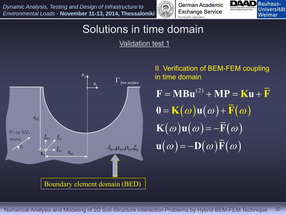
Solutions in time domain
32
P- or SV- wave
θ 0x
0f02f
01f01x
02x
0 0 0 0, , ,
free surface
Boundary element domain (BED)
1x
2x
Validation test 1
II. Verification of BEM-FEM coupling in time domain
(2)
F MBu MP u0 u
K FK
K
F
u F
u D F
Numerical Analysis and Modeling of 2D Soil-Structure Interaction Problems by Hybrid BEM-FEM Technique
Dynamic Analysis, Testing and Design of Infrastructure to
Environmental Loads - November 11-13, 2014, Thessaloniki
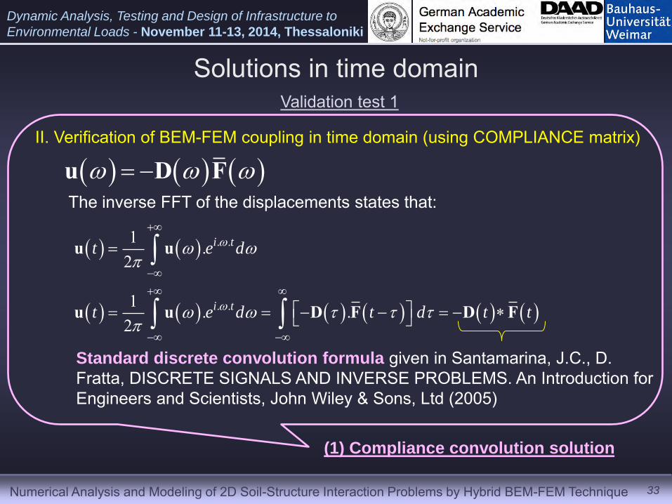
Solutions in time domain
33
Validation test 1
II. Verification of BEM-FEM coupling in time domain (using COMPLIANCE matrix)
u D FThe inverse FFT of the displacements states that:
. .
. .
1 .2
1 . .2
i t
i t
t e d
t e d t d t t
u u
u u D F D F
Standard discrete convolution formula given in Santamarina, J.C., D. Fratta, DISCRETE SIGNALS AND INVERSE PROBLEMS. An Introduction for Engineers and Scientists, John Wiley & Sons, Ltd (2005)
(1) Compliance convolution solution
Numerical Analysis and Modeling of 2D Soil-Structure Interaction Problems by Hybrid BEM-FEM Technique
Dynamic Analysis, Testing and Design of Infrastructure to
Environmental Loads - November 11-13, 2014, Thessaloniki
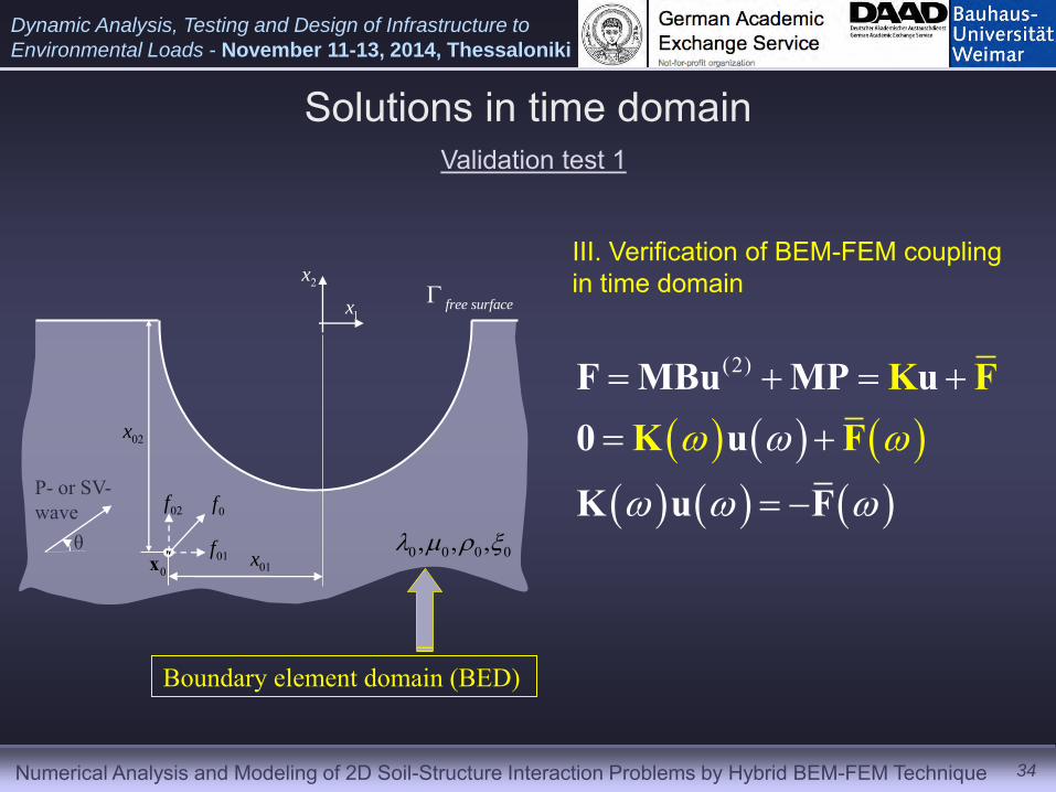
Solutions in time domain
34
P- or SV- wave
θ 0x
0f02f
01f01x
02x
0 0 0 0, , ,
free surface
Boundary element domain (BED)
1x
2x
Validation test 1
III. Verification of BEM-FEM coupling in time domain
(2)
F MBu MP u0
K
Fu
u
FK
F
K
Numerical Analysis and Modeling of 2D Soil-Structure Interaction Problems by Hybrid BEM-FEM Technique
Dynamic Analysis, Testing and Design of Infrastructure to
Environmental Loads - November 11-13, 2014, Thessaloniki
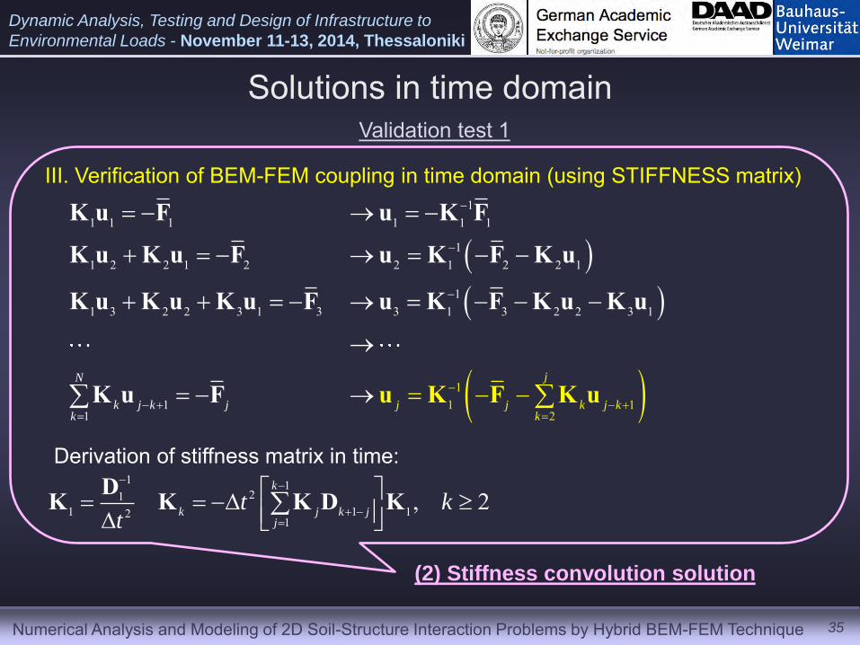
Solutions in time domain
35
Validation test 1
III. Verification of BEM-FEM coupling in time domain (using STIFFNESS matrix)
(2) Stiffness convolution solution
11 1 1 1 1 1
11 2 2 1 2 2 1 2 2 1
1
11 1
2
1 3 2 2 3 1 3 3 1 3 2 2 3 1
11
jN
k j j j kk
k jk
j k
K u F u K F
K u K u F u K F K u
K u K u K u F u K F K u K u
K u F u K F K u
1 121
1 1 121
, 2k
k j k jj
t kt
DK K K D K
Derivation of stiffness matrix in time:
Numerical Analysis and Modeling of 2D Soil-Structure Interaction Problems by Hybrid BEM-FEM Technique
Dynamic Analysis, Testing and Design of Infrastructure to
Environmental Loads - November 11-13, 2014, Thessaloniki
Solutions in time domain
36
Validation test 1
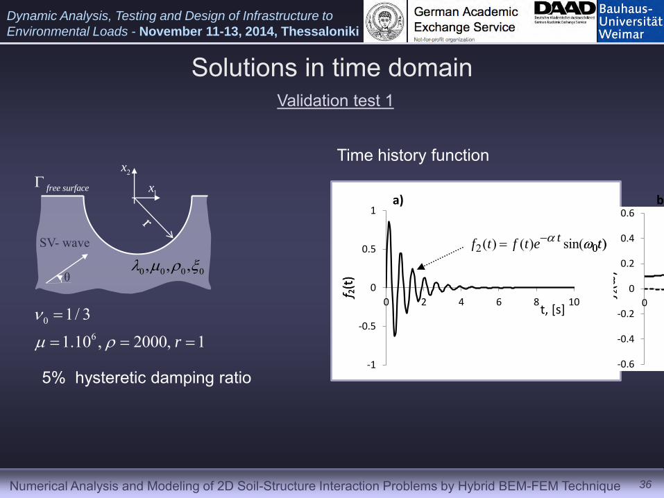
SV- wave
θ 0 0 0 0, , ,
free surface1x
2x
0
6
1/ 3
1.10 , 2000, 1r
5% hysteretic damping ratio
-1
-0.5
0
0.5
1
0 2 4 6 8 10
u(t)
-0.6
-0.4
-0.2
0
0.2
0.4
0.6
0 1 2 3 4 5
u(ω)
Re Im Abs
2 0( ) ( ) sin( )tf t f t e t
220
02 )()(
)(
if
f 2(t
)
f 2(ω
)
f, [Hz] t, [s]
-1
-0.5
0
0.5
1
0 2 4 6 8 10
u(t)
-0.6
-0.4
-0.2
0
0.2
0.4
0.6
0 1 2 3 4 5
u(ω)
Re Im Abs
a) b)
2 0( ) ( ) sin( )tf t f t e t
220
02 )()(
)(
if
f 2(t
)
f 2(ω
)
f, [Hz] t, [s]
Time history function

Numerical Analysis and Modeling of 2D Soil-Structure Interaction Problems by Hybrid BEM-FEM Technique
Dynamic Analysis, Testing and Design of Infrastructure to
Environmental Loads - November 11-13, 2014, Thessaloniki
Solutions in time domain
37
-1
-0.5
0
0.5
1
0 1 2 3 4 5 6
(0) canyon time solution
(1) compliance convolution solution
(2) stiffness convolution solution Nyquist frequency=5 Hz
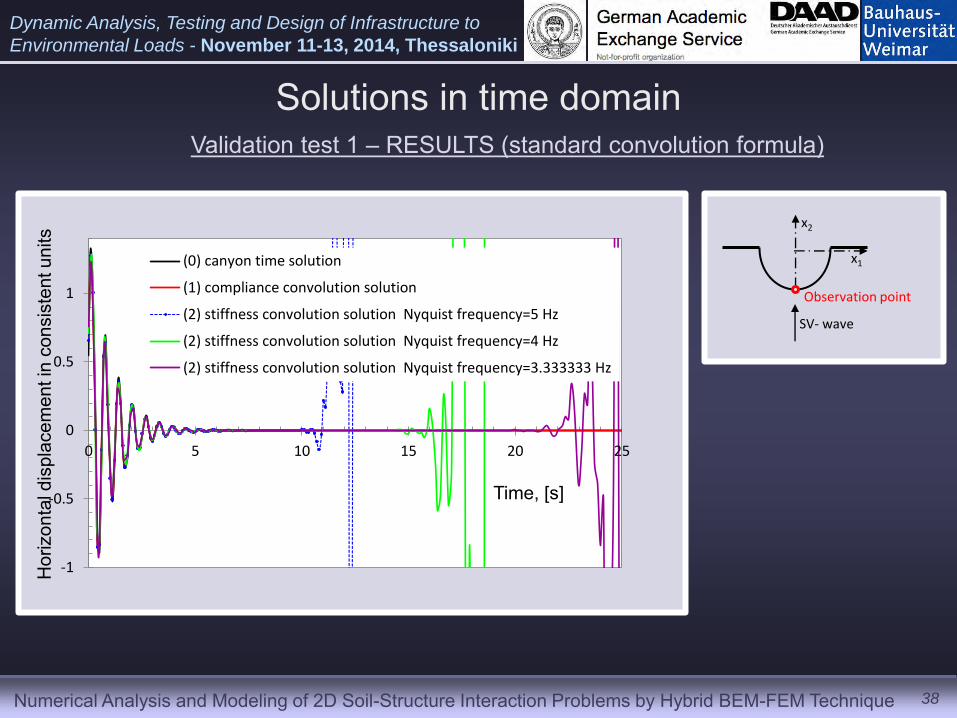
Validation test 1 – RESULTS (standard convolution formula)
x1
x2
SV- wave
Observation point
Time, [s]
Hor
izon
tal d
ispl
acem
ent i
n co
nsis
tent
uni
ts
Numerical Analysis and Modeling of 2D Soil-Structure Interaction Problems by Hybrid BEM-FEM Technique
Dynamic Analysis, Testing and Design of Infrastructure to
Environmental Loads - November 11-13, 2014, Thessaloniki
Solutions in time domain
38
x1
x2
SV- wave
Observation point
-1
-0.5
0
0.5
1
0 5 10 15 20 25
(0) canyon time solution
(1) compliance convolution solution
(2) stiffness convolution solution Nyquist frequency=5 Hz
(2) stiffness convolution solution Nyquist frequency=4 Hz
(2) stiffness convolution solution Nyquist frequency=3.333333 Hz
Time, [s]
Hor
izon
tal d
ispl
acem
ent i
n co
nsis
tent
uni
ts
Validation test 1 – RESULTS (standard convolution formula)

Numerical Analysis and Modeling of 2D Soil-Structure Interaction Problems by Hybrid BEM-FEM Technique
Dynamic Analysis, Testing and Design of Infrastructure to
Environmental Loads - November 11-13, 2014, Thessaloniki
-1
-0.5
0
0.5
1
0 1 2 3 4 5 6
(0) canyon time solution
(1) compliance convolution solution
(2) stiffness convolution solution Nyquist frequency=5 Hz
(4) ANSYS
Solutions in time domain
39
x1
x2
SV- wave
Observation point
Time, [s]
Hor
izon
tal d
ispl
acem
ent i
n co
nsis
tent
uni
ts
Validation test 1 – RESULTS (standard convolution formula)
Numerical Analysis and Modeling of 2D Soil-Structure Interaction Problems by Hybrid BEM-FEM Technique
Dynamic Analysis, Testing and Design of Infrastructure to
Environmental Loads - November 11-13, 2014, Thessaloniki
Solutions in time domain
40
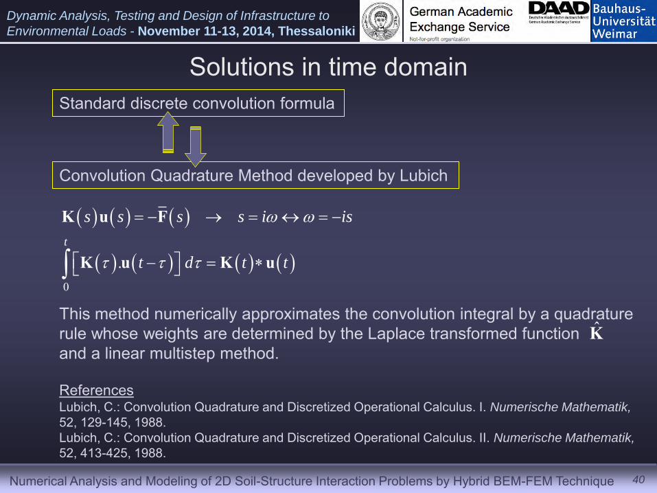
Standard discrete convolution formula
Convolution Quadrature Method developed by Lubich
0
.t
s s s s i is
t d t t
K u F
K u K u
This method numerically approximates the convolution integral by a quadrature rule whose weights are determined by the Laplace transformed function and a linear multistep method.
K̂
Lubich, C.: Convolution Quadrature and Discretized Operational Calculus. I. Numerische Mathematik,
52, 129-145, 1988. Lubich, C.: Convolution Quadrature and Discretized Operational Calculus. II. Numerische Mathematik,
52, 413-425, 1988.
References
Numerical Analysis and Modeling of 2D Soil-Structure Interaction Problems by Hybrid BEM-FEM Technique
Dynamic Analysis, Testing and Design of Infrastructure to
Environmental Loads - November 11-13, 2014, Thessaloniki
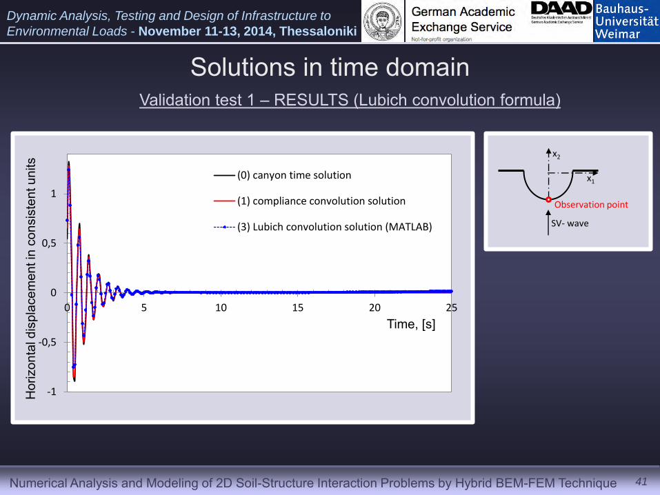
-1
-0,5
0
0,5
1
0 5 10 15 20 25
(0) canyon time solution
(1) compliance convolution solution
(3) Lubich convolution solution (MATLAB)
Solutions in time domain
41
x1
x2
SV- wave
Observation point
Time, [s]
Hor
izon
tal d
ispl
acem
ent i
n co
nsis
tent
uni
ts
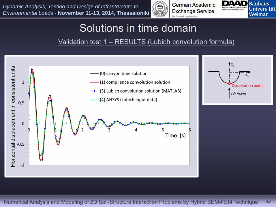
Validation test 1 – RESULTS (Lubich convolution formula)
Numerical Analysis and Modeling of 2D Soil-Structure Interaction Problems by Hybrid BEM-FEM Technique
Dynamic Analysis, Testing and Design of Infrastructure to
Environmental Loads - November 11-13, 2014, Thessaloniki
-1
-0,5
0
0,5
1
0 1 2 3 4 5 6
(0) canyon time solution
(1) compliance convolution solution
(3) Lubich convolution solution (MATLAB)
(4) ANSYS (Lubich input data)
Solutions in time domain
42
x1
x2
SV- wave
Observation point
Time, [s]
Hor
izon
tal d
ispl
acem
ent i
n co
nsis
tent
uni
ts
Validation test 1 – RESULTS (Lubich convolution formula)
Numerical Analysis and Modeling of 2D Soil-Structure Interaction Problems by Hybrid BEM-FEM Technique
Dynamic Analysis, Testing and Design of Infrastructure to
Environmental Loads - November 11-13, 2014, Thessaloniki
43
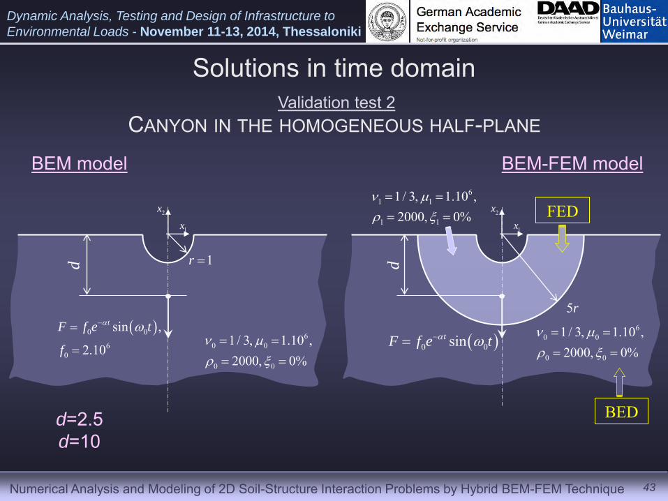
CANYON IN THE HOMOGENEOUS HALF-PLANE
60 0
0 0
1/ 3, 1.10 ,2000, 0%
0 0
60
sin ,
2.10
tF f e t
f
1r d
1x
2x
1x
2x
0 0sintF f e t 6
0 0
0 0
1/ 3, 1.10 ,2000, 0%
61 1
1 1
1/ 3, 1.10 ,2000, 0%
FED
BED
5r
BEM model BEM-FEM model
d
d=2.5 d=10
Solutions in time domain Validation test 2
Numerical Analysis and Modeling of 2D Soil-Structure Interaction Problems by Hybrid BEM-FEM Technique
Dynamic Analysis, Testing and Design of Infrastructure to
Environmental Loads - November 11-13, 2014, Thessaloniki
-0.8
-0.6
-0.4
-0.2
0
0.2
0.4
0 1 2 3 4 5 6
(0) canyon time solution
(4) ANSYS Lubich input
44
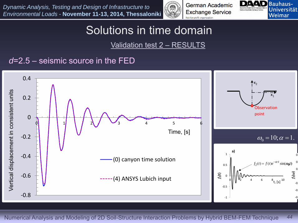
Solutions in time domain Validation test 2 – RESULTS
Time, [s]
Verti
cal d
ispl
acem
ent i
n co
nsis
tent
uni
ts
x1
x2
Observation
point
d=2.5 – seismic source in the FED
-1
-0.5
0
0.5
1
0 2 4 6 8 10
u(t)
-0.6
-0.4
-0.2
0
0.2
0.4
0.6
0 1 2 3 4 5
u(ω)
Re Im Abs
2 0( ) ( ) sin( )tf t f t e t
220
02 )()(
)(
if
f 2(t
)
f 2(ω
)
f, [Hz] t, [s]
-1
-0.5
0
0.5
1
0 2 4 6 8 10
u(t)
-0.6
-0.4
-0.2
0
0.2
0.4
0.6
0 1 2 3 4 5
u(ω)
Re Im Abs
a) b)
2 0( ) ( ) sin( )tf t f t e t
220
02 )()(
)(
if
f 2(t
)
f 2(ω
)
f, [Hz] t, [s]
0 10; 1.
Numerical Analysis and Modeling of 2D Soil-Structure Interaction Problems by Hybrid BEM-FEM Technique
Dynamic Analysis, Testing and Design of Infrastructure to
Environmental Loads - November 11-13, 2014, Thessaloniki
-0.4
-0.35
-0.3
-0.25
-0.2
-0.15
-0.1
-0.05
0
0.05
0.1
0 1 2 3 4 5 6
(0) canyon time solution
(4) ANSYS Lubich input
45
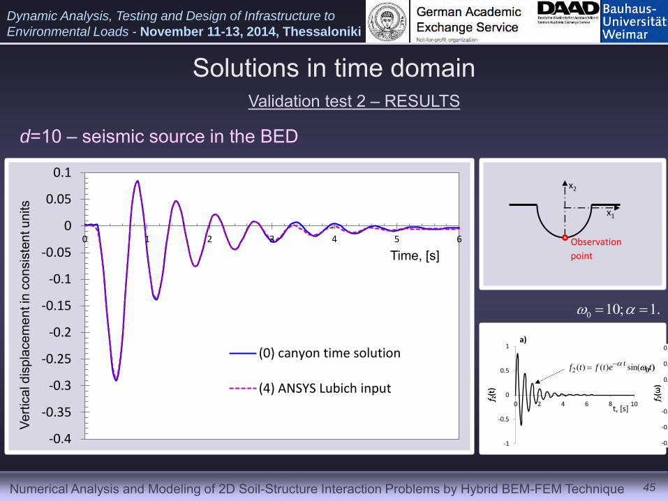
Solutions in time domain Validation test 2 – RESULTS
Time, [s]
Verti
cal d
ispl
acem
ent i
n co
nsis
tent
uni
ts
d=10 – seismic source in the BED
-1
-0.5
0
0.5
1
0 2 4 6 8 10
u(t)
-0.6
-0.4
-0.2
0
0.2
0.4
0.6
0 1 2 3 4 5
u(ω)
Re Im Abs
2 0( ) ( ) sin( )tf t f t e t
220
02 )()(
)(
if
f 2(t
)
f 2(ω
)
f, [Hz] t, [s]
-1
-0.5
0
0.5
1
0 2 4 6 8 10
u(t)
-0.6
-0.4
-0.2
0
0.2
0.4
0.6
0 1 2 3 4 5
u(ω)
Re Im Abs
a) b)
2 0( ) ( ) sin( )tf t f t e t
220
02 )()(
)(
if
f 2(t
)
f 2(ω
)
f, [Hz] t, [s]
0 10; 1.
x1
x2
Observation
point

Numerical Analysis and Modeling of 2D Soil-Structure Interaction Problems by Hybrid BEM-FEM Technique
Dynamic Analysis, Testing and Design of Infrastructure to
Environmental Loads - November 11-13, 2014, Thessaloniki
46
Solutions in time domain Validation test 2 – RESULTS
Time, [s]
Verti
cal d
ispl
acem
ent i
n co
nsis
tent
uni
ts
d=10 – seismic source in the BED
-1
-0.5
0
0.5
1
0 2 4 6 8 10
u(t)
-0.6
-0.4
-0.2
0
0.2
0.4
0.6
0 1 2 3 4 5
u(ω)
Re Im Abs
2 0( ) ( ) sin( )tf t f t e t
220
02 )()(
)(
if
f 2(t
)
f 2(ω
)
f, [Hz] t, [s]
-1
-0.5
0
0.5
1
0 2 4 6 8 10
u(t)
-0.6
-0.4
-0.2
0
0.2
0.4
0.6
0 1 2 3 4 5
u(ω)
Re Im Abs
a) b)
2 0( ) ( ) sin( )tf t f t e t
220
02 )()(
)(
if
f 2(t
)
f 2(ω
)
f, [Hz] t, [s]
0 10; 0.3
x1
x2
Observation
point
-0.4
-0.3
-0.2
-0.1
0
0.1
0.2
0 2 4 6 8 10 12 14
(0) canyon time solution
(4) ANSYS Lubich input