some thoughts on strategies for building block approach
TRANSCRIPT
PR
IVÉ
ET
CO
NF
IDE
NT
IEL
© B
om
bard
ier
Inc.
ou s
es f
iliale
s.
Tous d
roits r
éserv
és.
Some Thoughts on
Strategies for Building
Block Approach
Development
Eric Pomerleau
Isabelle Paris
FAA/Bombardier/TCCA/EASA/Industry
Composite Transport Damage Tolerance and
Maintenance Workshop
September 2015
PR
IVÉ
ET
CO
NF
IDE
NT
IEL
© B
om
bard
ier
Inc.
ou s
es f
iliale
s.
Tous d
roits r
éserv
és.
Summary
2
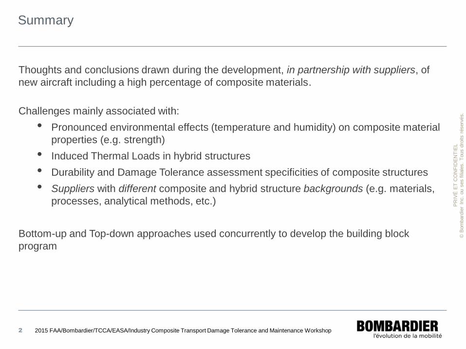
Thoughts and conclusions drawn during the development, in partnership with suppliers, of
new aircraft including a high percentage of composite materials.
Challenges mainly associated with:
• Pronounced environmental effects (temperature and humidity) on composite material
properties (e.g. strength)
• Induced Thermal Loads in hybrid structures
• Durability and Damage Tolerance assessment specificities of composite structures
• Suppliers with different composite and hybrid structure backgrounds (e.g. materials,
processes, analytical methods, etc.)
Bottom-up and Top-down approaches used concurrently to develop the building block
program
2015 FAA/Bombardier/TCCA/EASA/Industry Composite Transport Damage Tolerance and Maintenance Workshop
PR
IVÉ
ET
CO
NF
IDE
NT
IEL
© B
om
bard
ier
Inc.
ou s
es f
iliale
s.
Tous d
roits r
éserv
és.
Background (Building Block Pyramid)
3
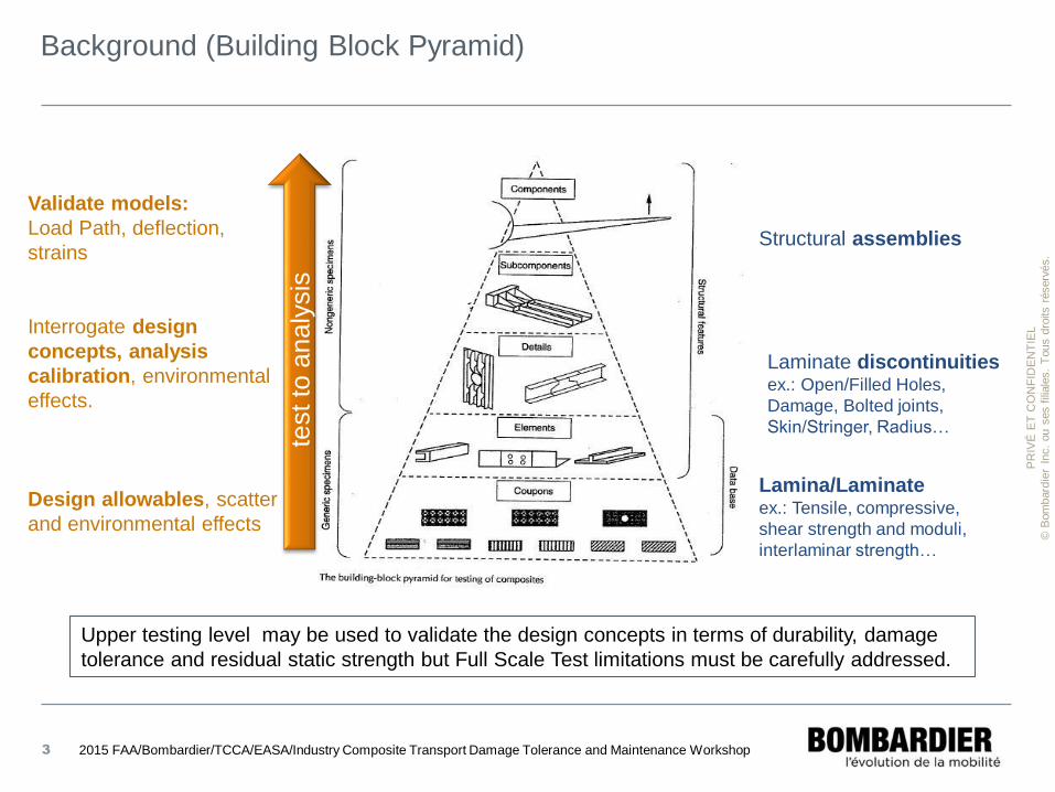
Validate models:
Load Path, deflection,
strains
Interrogate design
concepts, analysis
calibration, environmental
effects.
Design allowables, scatter
and environmental effects
Lamina/Laminate ex.: Tensile, compressive,
shear strength and moduli,
interlaminar strength…
Laminate discontinuities ex.: Open/Filled Holes,
Damage, Bolted joints,
Skin/Stringer, Radius…
Structural assemblies
test to
an
aly
sis
2015 FAA/Bombardier/TCCA/EASA/Industry Composite Transport Damage Tolerance and Maintenance Workshop
Upper testing level may be used to validate the design concepts in terms of durability, damage
tolerance and residual static strength but Full Scale Test limitations must be carefully addressed.
PR
IVÉ
ET
CO
NF
IDE
NT
IEL
© B
om
bard
ier
Inc.
ou s
es f
iliale
s.
Tous d
roits r
éserv
és.
Building Block development (Bottom-up)
4 2015 FAA/Bombardier/TCCA/EASA/Industry Composite Transport Damage Tolerance and Maintenance Workshop
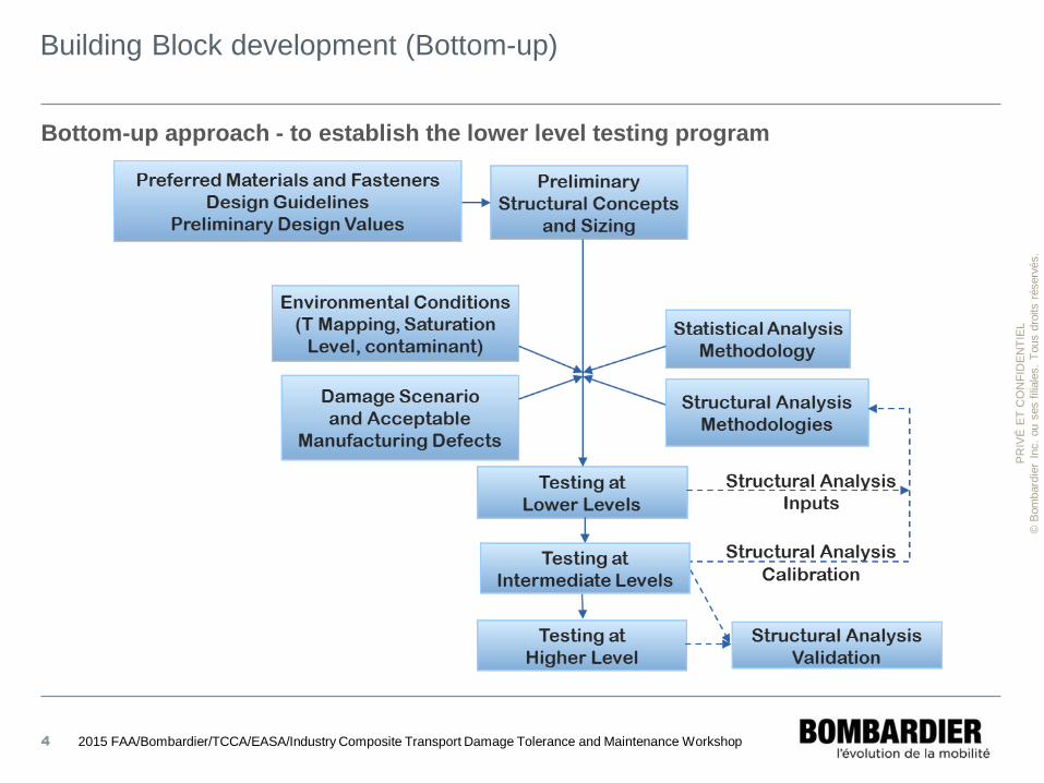
Bottom-up approach - to establish the lower level testing program
PR
IVÉ
ET
CO
NF
IDE
NT
IEL
© B
om
bard
ier
Inc.
ou s
es f
iliale
s.
Tous d
roits r
éserv
és.
Building Block development (Bottom-up)
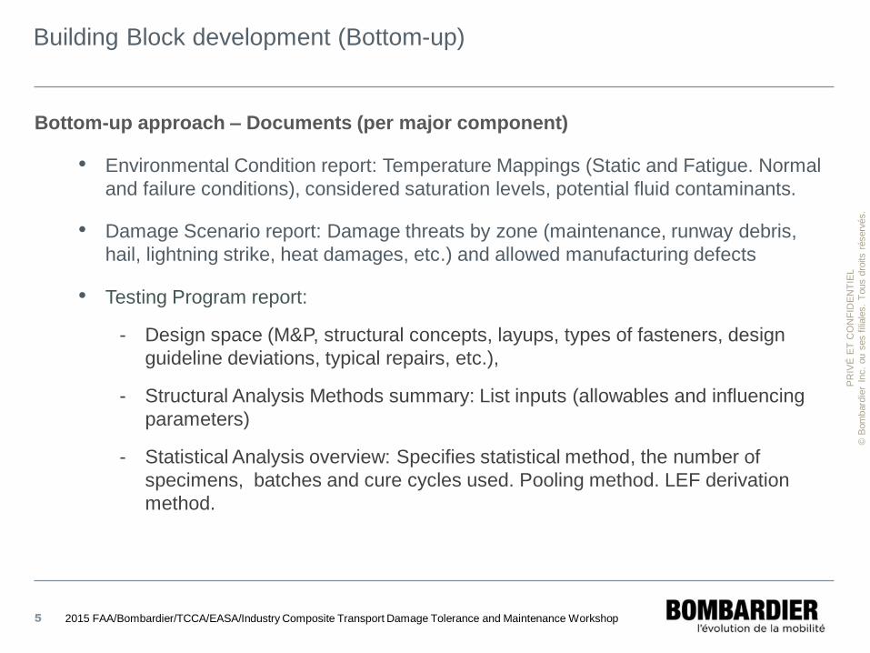
Bottom-up approach – Documents (per major component)
• Environmental Condition report: Temperature Mappings (Static and Fatigue. Normal
and failure conditions), considered saturation levels, potential fluid contaminants.
• Damage Scenario report: Damage threats by zone (maintenance, runway debris,
hail, lightning strike, heat damages, etc.) and allowed manufacturing defects
• Testing Program report:
- Design space (M&P, structural concepts, layups, types of fasteners, design
guideline deviations, typical repairs, etc.),
- Structural Analysis Methods summary: List inputs (allowables and influencing
parameters)
- Statistical Analysis overview: Specifies statistical method, the number of
specimens, batches and cure cycles used. Pooling method. LEF derivation
method.
5 2015 FAA/Bombardier/TCCA/EASA/Industry Composite Transport Damage Tolerance and Maintenance Workshop
PR
IVÉ
ET
CO
NF
IDE
NT
IEL
© B
om
bard
ier
Inc.
ou s
es f
iliale
s.
Tous d
roits r
éserv
és.
Building Block development (Bottom-up)
6
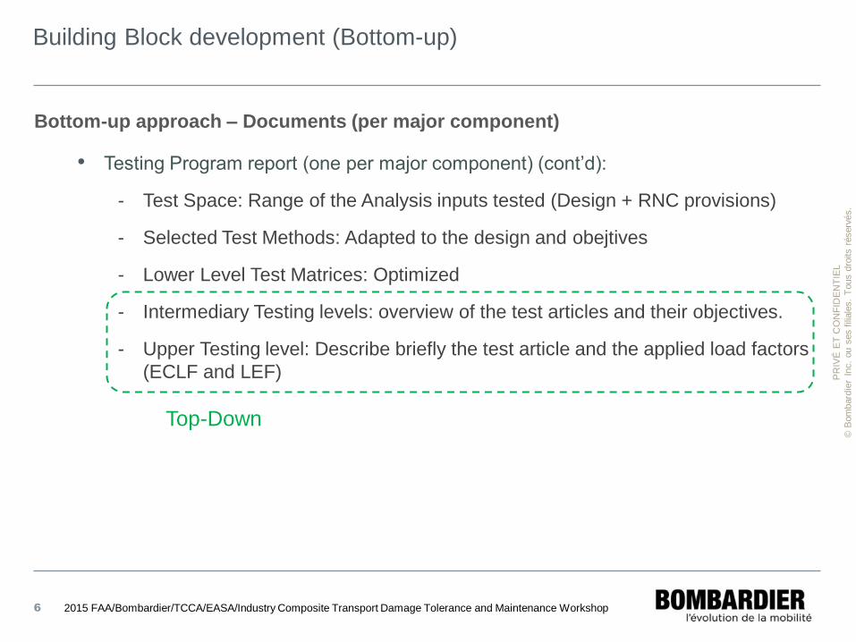
Bottom-up approach – Documents (per major component)
• Testing Program report (one per major component) (cont’d):
- Test Space: Range of the Analysis inputs tested (Design + RNC provisions)
- Selected Test Methods: Adapted to the design and obejtives
- Lower Level Test Matrices: Optimized
- Intermediary Testing levels: overview of the test articles and their objectives.
- Upper Testing level: Describe briefly the test article and the applied load factors
(ECLF and LEF)
2015 FAA/Bombardier/TCCA/EASA/Industry Composite Transport Damage Tolerance and Maintenance Workshop
Top-Down
PR
IVÉ
ET
CO
NF
IDE
NT
IEL
© B
om
bard
ier
Inc.
ou s
es f
iliale
s.
Tous d
roits r
éserv
és.
Building Block development (Bottom-up)
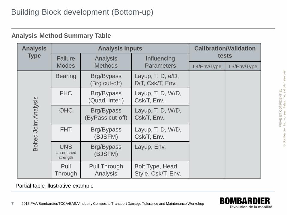
Partial table illustrative example
Analysis
Type
Analysis Inputs Calibration/Validation
tests Failure
Modes
Analysis
Methods
Influencing
Parameters L4/Env/Type L3/Env/Type
Bearing Brg/Bypass
(Brg cut-off)
Layup, T, D, e/D,
D/T, Csk/T, Env.
FHC Brg/Bypass
(Quad. Inter.)
Layup, T, D, W/D,
Csk/T, Env.
OHC Brg/Bypass
(ByPass cut-off)
Layup, T, D, W/D,
Csk/T, Env.
FHT Brg/Bypass
(BJSFM)
Layup, T, D, W/D,
Csk/T, Env.
UNS Un-notched
strength
Brg/Bypass
(BJSFM)
Layup, Env.
Pull
Through
Pull Through
Analysis
Bolt Type, Head
Style, Csk/T, Env.
7
Analysis Method Summary Table B
olted J
oin
t A
naly
sis
2015 FAA/Bombardier/TCCA/EASA/Industry Composite Transport Damage Tolerance and Maintenance Workshop
PR
IVÉ
ET
CO
NF
IDE
NT
IEL
© B
om
bard
ier
Inc.
ou s
es f
iliale
s.
Tous d
roits r
éserv
és.
Building Block development (Bottom-up)
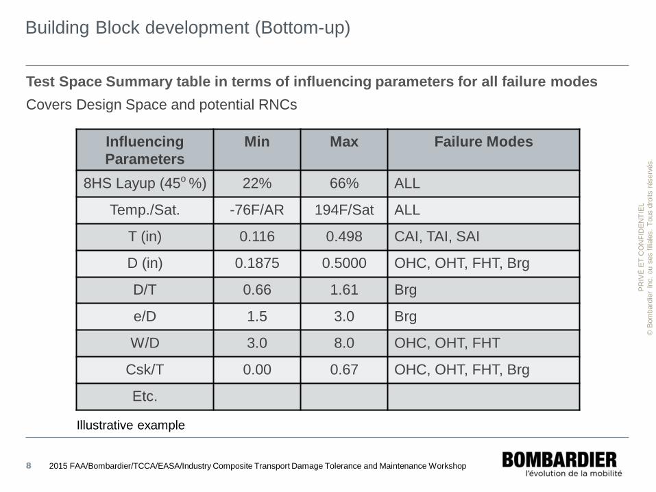
Test Space Summary table in terms of influencing parameters for all failure modes
Covers Design Space and potential RNCs
Influencing
Parameters
Min Max Failure Modes
8HS Layup (45o %) 22% 66% ALL
Temp./Sat. -76F/AR 194F/Sat ALL
T (in) 0.116 0.498 CAI, TAI, SAI
D (in) 0.1875 0.5000 OHC, OHT, FHT, Brg
D/T 0.66 1.61 Brg
e/D 1.5 3.0 Brg
W/D 3.0 8.0 OHC, OHT, FHT
Csk/T 0.00 0.67 OHC, OHT, FHT, Brg
Etc.
Illustrative example
8 2015 FAA/Bombardier/TCCA/EASA/Industry Composite Transport Damage Tolerance and Maintenance Workshop
PR
IVÉ
ET
CO
NF
IDE
NT
IEL
© B
om
bard
ier
Inc.
ou s
es f
iliale
s.
Tous d
roits r
éserv
és.
Building Block development (Top-down)
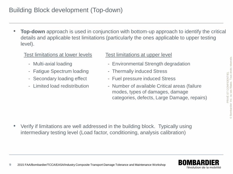
• Top-down approach is used in conjunction with bottom-up approach to identify the critical
details and applicable test limitations (particularly the ones applicable to upper testing
level).
9
Test limitations at lower levels
- Multi-axial loading
- Fatigue Spectrum loading
- Secondary loading effect
- Limited load redistribution
Test limitations at upper level
- Environmental Strength degradation
- Thermally induced Stress
- Fuel pressure induced Stress
- Number of available Critical areas (failure
modes, types of damages, damage
categories, defects, Large Damage, repairs)
• Verify if limitations are well addressed in the building block. Typically using
intermediary testing level (Load factor, conditioning, analysis calibration)
2015 FAA/Bombardier/TCCA/EASA/Industry Composite Transport Damage Tolerance and Maintenance Workshop
PR
IVÉ
ET
CO
NF
IDE
NT
IEL
© B
om
bard
ier
Inc.
ou s
es f
iliale
s.
Tous d
roits r
éserv
és.
Building Block development (Top-down)
10
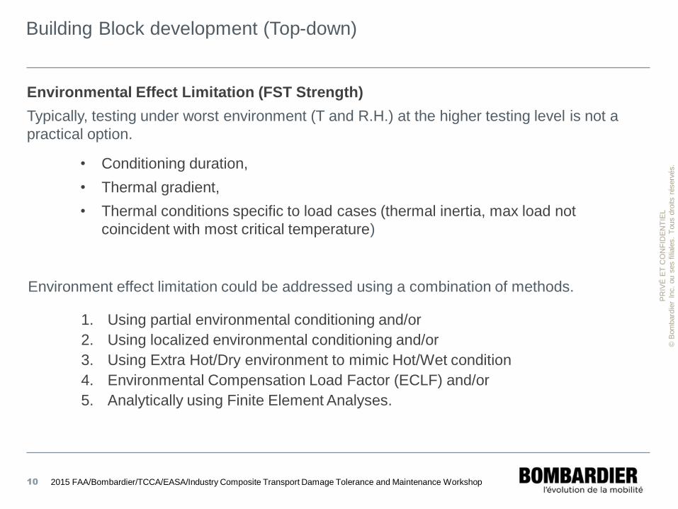
Environmental Effect Limitation (FST Strength)
Typically, testing under worst environment (T and R.H.) at the higher testing level is not a
practical option.
• Conditioning duration,
• Thermal gradient,
• Thermal conditions specific to load cases (thermal inertia, max load not
coincident with most critical temperature)
2015 FAA/Bombardier/TCCA/EASA/Industry Composite Transport Damage Tolerance and Maintenance Workshop
Environment effect limitation could be addressed using a combination of methods.
1. Using partial environmental conditioning and/or
2. Using localized environmental conditioning and/or
3. Using Extra Hot/Dry environment to mimic Hot/Wet condition
4. Environmental Compensation Load Factor (ECLF) and/or
5. Analytically using Finite Element Analyses.
PR
IVÉ
ET
CO
NF
IDE
NT
IEL
© B
om
bard
ier
Inc.
ou s
es f
iliale
s.
Tous d
roits r
éserv
és.
Building Block development (Top-down)
11
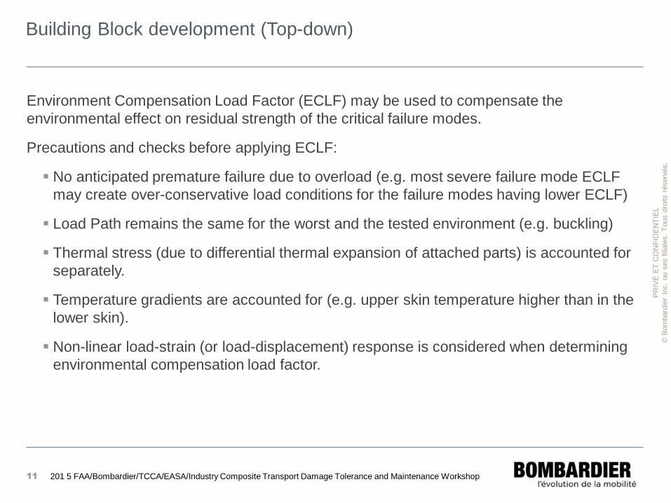
Environment Compensation Load Factor (ECLF) may be used to compensate the
environmental effect on residual strength of the critical failure modes.
Precautions and checks before applying ECLF:
No anticipated premature failure due to overload (e.g. most severe failure mode ECLF
may create over-conservative load conditions for the failure modes having lower ECLF)
Load Path remains the same for the worst and the tested environment (e.g. buckling)
Thermal stress (due to differential thermal expansion of attached parts) is accounted for
separately.
Temperature gradients are accounted for (e.g. upper skin temperature higher than in the
lower skin).
Non-linear load-strain (or load-displacement) response is considered when determining
environmental compensation load factor.
201 5 FAA/Bombardier/TCCA/EASA/Industry Composite Transport Damage Tolerance and Maintenance Workshop
PR
IVÉ
ET
CO
NF
IDE
NT
IEL
© B
om
bard
ier
Inc.
ou s
es f
iliale
s.
Tous d
roits r
éserv
és.
Building Block development (Top-down)
12
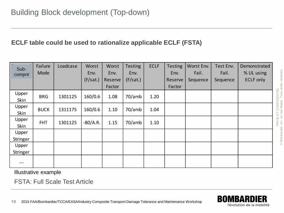
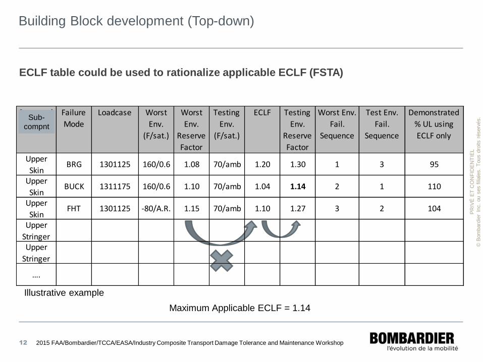
ECLF table could be used to rationalize applicable ECLF (FSTA)
Illustrative example
FSTA: Full Scale Test Article
Structural
Element
Failure
Mode
Loadcase Worst
Env.
(F/sat.)
Worst
Env.
Reserve
Factor
Testing
Env.
(F/sat.)
ECLF Testing
Env.
Reserve
Factor
Worst Env.
Fail.
Sequence
Test Env.
Fail.
Sequence
Demonstrated
% UL using
ECLF only
Upper
SkinBRG 1301125 160/0.6 1.08 70/amb 1.20
Upper
SkinBUCK 1311175 160/0.6 1.10 70/amb 1.04
Upper
SkinFHT 1301125 -80/A.R. 1.15 70/amb 1.10
Upper
StringerUpper
Stringer
….
2015 FAA/Bombardier/TCCA/EASA/Industry Composite Transport Damage Tolerance and Maintenance Workshop
Sub-
compnt
PR
IVÉ
ET
CO
NF
IDE
NT
IEL
© B
om
bard
ier
Inc.
ou s
es f
iliale
s.
Tous d
roits r
éserv
és.
Building Block development (Top-down)
12
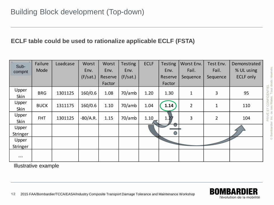
ECLF table could be used to rationalize applicable ECLF (FSTA)
Illustrative example
Maximum Applicable ECLF = 1.14
Structural
Element
Failure
Mode
Loadcase Worst
Env.
(F/sat.)
Worst
Env.
Reserve
Factor
Testing
Env.
(F/sat.)
ECLF Testing
Env.
Reserve
Factor
Worst Env.
Fail.
Sequence
Test Env.
Fail.
Sequence
Demonstrated
% UL using
ECLF only
Upper
SkinBRG 1301125 160/0.6 1.08 70/amb 1.20 1.30 1 3 95
Upper
SkinBUCK 1311175 160/0.6 1.10 70/amb 1.04 1.14 2 1 110
Upper
SkinFHT 1301125 -80/A.R. 1.15 70/amb 1.10 1.27 3 2 104
Upper
StringerUpper
Stringer
….
2015 FAA/Bombardier/TCCA/EASA/Industry Composite Transport Damage Tolerance and Maintenance Workshop
Sub-
compnt
PR
IVÉ
ET
CO
NF
IDE
NT
IEL
© B
om
bard
ier
Inc.
ou s
es f
iliale
s.
Tous d
roits r
éserv
és.
Building Block development (Top-down)
12
ECLF table could be used to rationalize applicable ECLF (FSTA)
Illustrative example
Structural
Element
Failure
Mode
Loadcase Worst
Env.
(F/sat.)
Worst
Env.
Reserve
Factor
Testing
Env.
(F/sat.)
ECLF Testing
Env.
Reserve
Factor
Worst Env.
Fail.
Sequence
Test Env.
Fail.
Sequence
Demonstrated
% UL using
ECLF only
Upper
SkinBRG 1301125 160/0.6 1.08 70/amb 1.20 1.30 1 3 95
Upper
SkinBUCK 1311175 160/0.6 1.10 70/amb 1.04 1.14 2 1 110
Upper
SkinFHT 1301125 -80/A.R. 1.15 70/amb 1.10 1.27 3 2 104
Upper
StringerUpper
Stringer
….
2015 FAA/Bombardier/TCCA/EASA/Industry Composite Transport Damage Tolerance and Maintenance Workshop
Sub-
compnt
PR
IVÉ
ET
CO
NF
IDE
NT
IEL
© B
om
bard
ier
Inc.
ou s
es f
iliale
s.
Tous d
roits r
éserv
és.
Building Block development (Top-down)
ECLF table may be used to determine:
• Changes in the Failure mode sequence between the tested environment and worst
environmental condition
• Zones where test environmental limitations (strength) apply (zones and failure
modes)
• Importance of existing gap (strength demo) if only ECLF is used
• Locations where special attention should be shown regarding the understanding of
load level (zones with limitations).
• Zones where the test limitations must be addressed analytically and/or by test at
intermediate testing level.
Note: ECLF table is less applicable in zones where thermal stress is relatively significant.
13 2015 FAA/Bombardier/TCCA/EASA/Industry Composite Transport Damage Tolerance and Maintenance Workshop
PR
IVÉ
ET
CO
NF
IDE
NT
IEL
© B
om
bard
ier
Inc.
ou s
es f
iliale
s.
Tous d
roits r
éserv
és.
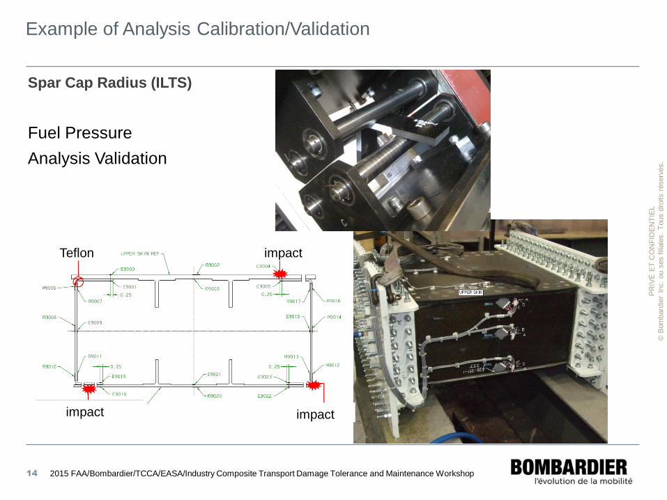
Example of Analysis Calibration/Validation
Spar Cap Radius (ILTS)
Fuel Pressure
Analysis Validation
14
Teflon
impact
impact
impact
2015 FAA/Bombardier/TCCA/EASA/Industry Composite Transport Damage Tolerance and Maintenance Workshop
PR
IVÉ
ET
CO
NF
IDE
NT
IEL
© B
om
bard
ier
Inc.
ou s
es f
iliale
s.
Tous d
roits r
éserv
és.
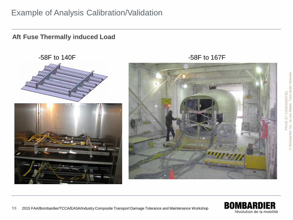
Example of Analysis Calibration/Validation
15
Aft Fuse Thermally induced Load
-58F to 140F -58F to 167F
2015 FAA/Bombardier/TCCA/EASA/Industry Composite Transport Damage Tolerance and Maintenance Workshop
PR
IVÉ
ET
CO
NF
IDE
NT
IEL
© B
om
bard
ier
Inc.
ou s
es f
iliale
s.
Tous d
roits r
éserv
és.
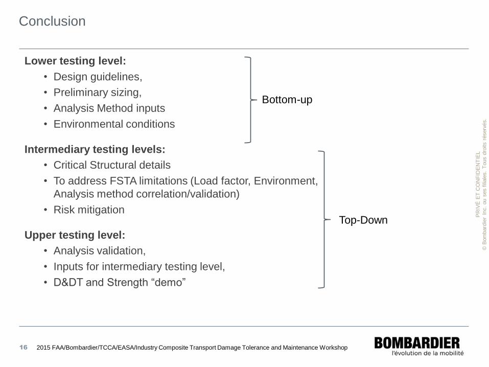
Conclusion
Lower testing level:
• Design guidelines,
• Preliminary sizing,
• Analysis Method inputs
• Environmental conditions
Intermediary testing levels:
• Critical Structural details
• To address FSTA limitations (Load factor, Environment,
Analysis method correlation/validation)
• Risk mitigation
Upper testing level:
• Analysis validation,
• Inputs for intermediary testing level,
• D&DT and Strength “demo”
16 2015 FAA/Bombardier/TCCA/EASA/Industry Composite Transport Damage Tolerance and Maintenance Workshop
Bottom-up
Top-Down