some results on digital chirp
TRANSCRIPT
1. Introduction
Some Results on Digital Chirp
S.C. IGLEHARTHughes Aircraft Company
Abstract
Generating chirp waveforms by means of phase coding yields a
simple, cost-effective mechanization. The coding process, however,
introduces phase errors whose effect must be included in the design.
An approximate analysis is presented, valid for moderate to high
compression ratios, which allows error effects on compressed pulse
amplitude and sidelobes to be calculated in a simple manner. The
anaylsis provides criteria for selecting the coding bit width (sample
rate), weighting network bandwidth, and phase-coder quantization
interval and transition times. Weighting functions for maximizing
the signal-to-noise ratio (SNR) or for producing desired close-in
sidelobe performance are derived, as is an exact expression for the
transmitted spectrum. Numerical results are presented for Gaussian
and the maximum-SNR weighting. The results indicate that per-
formance will be satisfactory for many applications.
Manuscript received 8, 1977; revised August 20, 1977.
Author's present address: 405 Strand, Santa Monica, CA 90405.
0018-9251/78/0100-0118 $00.75 1978 IEEE
The chirp waveform has enjoyed wide popularity due toits ease of mechanization and its Doppler insensitivity.Generating the chirp waveform, however, while straight-forward in principle, can be expensive. Generatinga polyphase coded waveform is frequently cheaper, lesscomplex, and provides better spectral purity. There is thuspotential advantage in generating the chirp waveform by ap-proximating its parabolic phase characteristic with a poly-phase code.
Given the phase-coded transmitted waveform, one cancompress it with a matched filter, whose impulse responseis also a phase-coded waveform (and might be implementeddigitally, or as an analog transversal filter), or one can re-gard the phase code as an approximation to the chirp wave-form and compress it using a dispersive delay line with acontinuous parabolic phase characteristic. We analyze thelatter method here. The potential advantages of using aconventional chirp compressive line, instead of a transver-sal filter, are twofold. The former avoids notches in theDoppler response, characteristic of polyphase codes. Inaddition, if surface acoustic wave techniques are used torealize the compression filter, the continuous filtqr yieldsa simpler and less critical metallization geometry than amatched transversal filter.
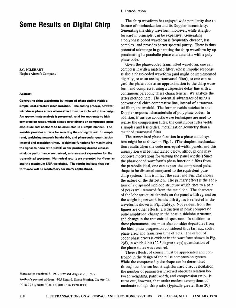
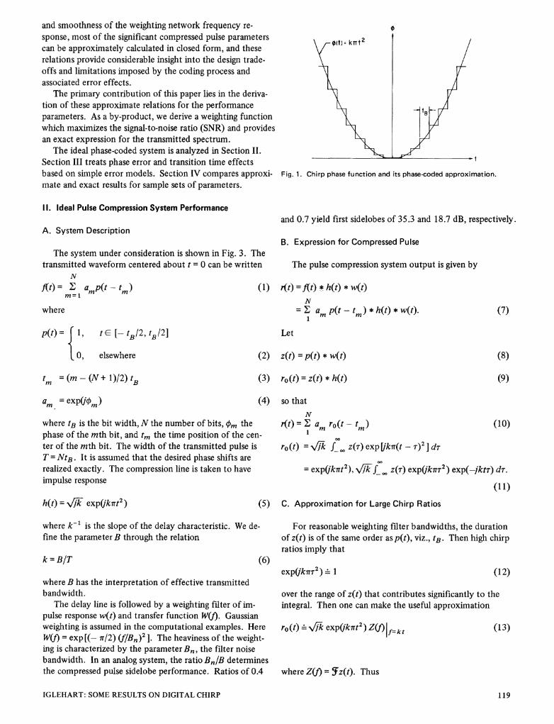
The transmitted phase function in a phase coded sys-tem might be as shown in Fig. 1. (The simplest mechaniza-tion results when the code uses equal-width panels, and thisassumption will be maintained below, although one mayconceive motivations for varying the panel widths.) Sincethe phase-coded waveform's phase function differs fromthe parabolic ideal, one can expect the compressed pulseshape to be distorted compared to the equivalent purechirp system. This is in fact the case, and Fig. 2(a) showsthe nature of the distortion. The primary effect is the addi-tion of a dispersed sidelobe structure which rises to a pairof peaks well removed from the mainlobe. The characterof the lobe structure depends on the panel width tB and onthe weighting network bandwidth Bn, as is reflected in thewaveforms shown in Fig. 2(a)(c). Not evident from thefigures are other effects: a reduction in peak compressedpulse amplitude, change in the near-in sidelobe structure,and change in the transmitted spectrum. In addition tothese phenomena, one must also consider departures fromthe ideal phase progression considered thus far, viz., coderphase error and transition time effects. The effect ofcoder phase errors is evident in the waveform shown in Fig.2(d), in which 4-bit (22.5-degree steps) quantization ofthe phase states was assumed.
These effects, of course, must be appreciated and con-trolled in the design of the pulse compression system.While the compressed pulse shape can be determinedthrough cumberson but straightforward direct calculation,the number of parameters involved obscures relation be-tween weighting, panel width, and compression ratio. Itturns out, however, that under modest assumptions ofmoderate-to-high chirp ratio (typically greater than 20)
IEEE TRANSACTIONS ON AEROSPACE AND ELECTRONIC SYSTEMS VOL. AES-14, NO. 1 JANUARY 1978118
and smoothness of the weighting network frequency re-sponse, most of the significant compressed pulse parameterscan be approximately calculated in closed form, and theserelations provide considerable insight into the design trade-offs and limitations imposed by the coding process andassociated error effects.
The primary contribution of this paper lies in the deriva-tion of these approximate relations for the performanceparameters. As a by-product, we derive a weighting functionwhich maximizes the signal-to-noise ratio (SNR) and providesan exact expression for the transmitted spectrum.
The ideal phase-coded system is analyzed in Section II.Section III treats phase error and transition time effectsbased on simple error models. Section IV compares approxi-mate and exact results for sample sets of parameters.
I. Ideal Pulse Compression System Performance
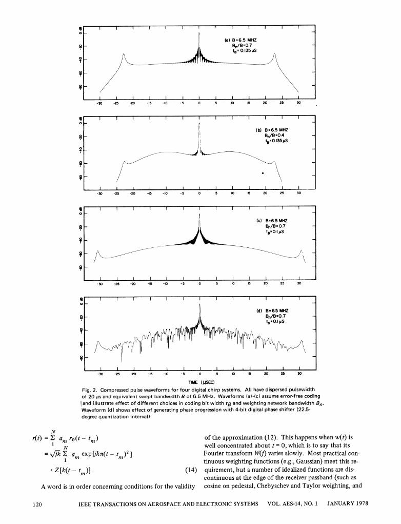
A. System Description
The system under consideration is shown in Fig. 3. Thetransmitted waveform centered about t = 0 can be written
N
fJt) = I amp(t-tm)m=
where
Fig. 1. Chirp phase function and its phase-coded approximation.
and 0.7 yield first sidelobes of 35.3 and 18.7 dB, respectively.
B. Expression for Compressed Pulse
The pulse compression system output is given by
(1) r(t) = f(t) * h(t) * w(t)N
= z am p(t - tm) * h(t) * w(t).I
Let
(7)
p(t)= II te[-stB/2,tBe/2
° elsewhere (2) z(t) = p(t) * w(t)
(3) ro(t) = z(t) * h(t)
am = exp(iUm) (4) so that
where tB is the bit width,N the number of bits, qm thephase of the mth bit, and tm the time position of the cen-
ter of the mth bit. The width of the transmitted pulse isT = NtB. It is assumed that the desired phase shifts are
realized exactly. The compression line is taken to haveimpulse response
h(t) = V/Y7 exp(fkrrt2) (c
N
r(t) = E am ro(t -tm )1
(10)
ro(t) = -, fk 0 z(r) exp [kir(t T)2 ] dr
exp(k7rt2), _f z(T) expQk7rr2) exp(-jktr) dr.
(1 1)
S) C. Approximation for Large Chirp Ratios
where k-' is the slope of the delay characteristic. We de-fine the parameter B through the relation
k = BIT
where B has the interpretation of effective transmittedbandwidth.
The delay line is followed by a weighting filter of im-pulse response w(t) and transfer function W(f). Gaussianweighting is assumed in the computational examples. HereW(f) = exp [(- 7r/2) (f/Bn)2 ]. The heaviness of the weight-ing is characterized by the parameter B,, the filter noisebandwidth. In an analog system, the ratio Bn/B determinesthe compressed pulse sidelobe performance. Ratios of 0.4
For reasonable weighting filter bandwidths, the durationof z(t) is of the same order as p(t), viz., tB. Then high chirpratios imply that
(6)exp(ik,rr2)_ 1 (12)
over the range of z(t) that contributes significantly to theintegral. Then one can make the useful approximation
ro (t) _Xk expQkirt2') Z(I) jf k t (13)
where Z(f) = -fz(t). Thus
IGLEHART: SOME RESULTS ON DIGITAL CHIRP
tm= (m (N + 1)/2) tB
(8)
(9)
119
I0
1 1
(b) B=6.5 MHZBe/BB0.4t -0.135)jS
~I I 1.-30 -25 -20 -IS -10 -5 0 10 20 25 30
o I
o (c) B=6.5 MHZBn/B= 0.7
-30 -25 -20 -15 -10 -5 0 5 10 I5 20 25 30
^.1 . . I
0I
(d) B - 6.5 MHZBn/B=0.7
\ ~~~~~~~to-O.i,uS
1r$S110 hA)
Il~j'
I I .I I-I0 -25 -20I. . . 0 ... . 2
-30 -25 -20 -15 -10 -5 0 S 10 5 20 25 30
TIME (JSEC)
Fig. 2. Compressed pulse waveforms for four digital chirp systems. All have dispersed pulsewidthof 20 Ms and equivalent swept bandwidth 8 of 6.5 MHz. Waveforms (a)-(c) assume error-free codingand illustrate effect of different choices in coding bit width tB and weighting network bandwidth Bn.Waveform (d) shows effect of generating phase progression with 4-bit digital phase shifter (22.5-degree quantization interval).
Nr(t) = I am ro(t - tmi) of the approximation (12). This happens when w(t) is
1 well concentrated about t = 0, which is to say that itsN
= NFk E am exp Ukr(t - tm )2j Fourier transform W(J) varies slowly. Most practical con-1 tinuous weighting functions (e.g., Gaussian) meet this re-
- Z[k(t - tm)I] (14) quirement, but a number of idealized functions are dis-continuous at the edge of the receiver passband (such as
A word is in order concerning conditions for the validity cosine on pedestal, Chebyschev and Taylor weighting, and
IEEE TRANSACTIONS ON AEROSPACE AND ELECTRONIC SYSTEMS VOL. AES-14, NO. 1 JANUARY 1978
-1 --I
(a) B 6.5 MHZBn/B=0.7
aI . W ~t, 0.135.uS
I I-30 -25 -20 -15 -10 - 5 0 5 10 IS 20 25 30
- 1- I I I I I II I~~~~~~~~~~~~~~~~~~~~~
120
i
MICRWA'E DIGITAL POWERSORE
- PHASEAMLFESlRE SHIFTER AMLFR
| CODE
|GENERATO)R|
TRANIMIIT F) SIGNALf t
m
C\j
TARGET RETURN | COMPRESSION WEIGHTING (MPRFSSED PULSETAGEETR DELAY LINE FILTER I(MRSE US
PULSFS H() W(f)|rI
Fig. 3. Pulse compression system block diagram.
a special weighting function to be developed subsequently).When discontinuities are present, a modification to thetheory is required. (In practice, of course, sharp discon-tinuities would be unlikely.) Since this modification ob-scures the insight that can be obtained from the simple re-lations (13) and (14), its development is deferred to theAppendix.
D. Choice of Phase Code
The phase weights can be chosen to maximize the com-pressed amplitude and hence the peak SNR. Under theassumptions that W(f) is real, positive, and even, and thattB < 2/B, Z [ktm ] is real and positive, so that r(O) ismaximized by taking
am = exp(- jk7rt2). (15
With this choice,N
t(t) - Xk exp(jkit2t) z exp(- j27rkttm)
EZP[k(tSin Lo * (16
E. Peak Signal Loss
) rP)U)0
-J
z(DU-)
wa-
02 04 0.6 0.8 1.0 1.2 14
Bt1
Fig. 4. Peak signal voltage loss for Gaussian weighting.
Fig. 4 shows PSVL as a function of the BtB product andthe weighting network bandwidth. The value at BtB = 0indicates the reduction in peak amplitude due to the
5) weighting network. The additional loss due to the steppedphase approximation is a fraction of a decibel for samplingabove the Nyquist rate (BtB = 1).
F. Peak SN R Loss
z) The signal-to-noise power ratio of a matched filter wouldbe SNR = TINo withNo the receiver noise power spectraldensity. The SNR of our system is defined as
At this point we can derive approximate relations for SNR = Ir(0) 12/Bn Nocertain quantities of interest. The peak amplitude of thecompressed pulse is given by where
N _r(O) = kV Z[k(- ttm)JI (17) B, =fL. IW(t)12df
Expressing the sum as a staircase approximation to an
integral yieldsB/2
r(0)- 3(N/B)f B/2 Z(f) df (18)
By way of contrast, the peak signal for an ideal unweightedchirp signal is V\BT. One can thus define a peak signalvoltage loss (PSVL) which reflects the effects of weightingand coding on the peak signal:
PSVL =Ir(O)I/BT (N/B7)LB/2Z(0)dfB/2~ ~ fB/B/2
= (1/B) B/2 W(f) SinC tBfdf
IGLEHART: SOME RESULTS ON DIGITAL CHIRP
is the weighting network noise bandwidth. The ratio ofthe two is the peak SNR loss (PSNRL):
PSNRL = Ir(O) 12/BnT. (22)
This can be written
PSNRL = (PSVL)2(B/Bn)
f-W() sinc tBfdf 12/Bf W()12 df.
(19) (23)
121
= X =f \ o<~~~~~~~~~Bn/B=I.00.9080.7 -
0.6
0.5
0.4
03
1 1 1
(20)
(21)

MOW' Dn/B =06a
cn 0.7,,(no~~~ ~ ~ ~~~~~~~<
C, o 005cr ~~~~~~~~~~~~~~~~~0
QtQ~~~~~t
0~
z 0Fg)5. P S l
Fig.6. Performance parameters fo matched weightingfunctionU).<~~~~~~~~~~~~~~~~~a--
Q U~~~~~~~~~~~~0
B t
Fig. 5. Peak SNR loss.
Fig. 6. Performance parameters for matched weighting function.
0 02 04 06 08 10 2
BtB
Fig. 7. Compressed pulse close-in sidelobe levels for Gaussianweighting.
matched weighting function.
H. Compressed Pulse Waveform in the Vicinity of theMainlobe
One may compute the sidelobe structure in the vicinityof the mainlobe by approximating the sum in (16) asfollows:
N
I exp [-j21Jk(t - tm)] Z [k(t - tm)]B/2
= (N/B) fB/2 exp(2irrtv) Z(kt - v) dv
=N f sinc B(t - r) z(t) exp(- j2irktr) dr.
For r < T/BtB, one has exp(- j27rktr) _ 1. The convolu-tion theorem and the definition of PSVL then yieldPSNRL is plotted in Fig. 5.
G. Choice of Weighting Function to Minimize SNR Loss
The "best" choice of weighting network transfer function,from the standpoint of maximizing SNR, maximizes (23).Clearly, one should set W(f) = 0 for If > B/2. The Cauchy-Schwarz inequality then yields
WM(f) = sinc tBf rect (f/B) (24)
as the minimizing function. This will be termed the matchedweighting function. Note the distinction between matchedweighting, in which only the receiver amplitude responseis optimized, and the matched filter, in which both ampli-tude and phase are optimized.
Fig. 6 shows PSVL, PSNRL, first sidelobe level (andother parameters to be discussed subsequently) for the
r(t)/r(O) (1 /PSVL) F1 {rect(f/B) W() sinc tBft I .
(26)
Fig. 7 shows the compressed pulse close-in sidelobe levelfor Gaussian weighting, computed using (26). Note thatphase coding improves the sidelobe performance, due tothe additional weighting provided by the sinc tBfterm in(26).
Equation (26) indicates that the envelope of the com-
pressed pulse, in the vicinity of the mainlobe, is approxi-mately the same as that in a passive chirp system withweighting function
WC(J)= W(f) sinc tBf. (27)
Thus one can obtain waveforms as produced by a classical
IEEE TRANSACTIONS ON AEROSPACE AND ELECTRONIC SYSTEMS VOL. AES-14, NO. 1 JANUARY 1978
BtB
00
0a)
0
CU
0.
0
0
0
Cn
C-Lco
(25)
am
122
band-limited weighting function W1(f) by taking
W(f) = Wc(I)/ sinc tBf. (28)
The zeros of sinc tBf must, of course, fall outside the re-ceiver passband.
1. Far-Out Sidelobe Peaks
The sidelobe structure corresponds to (26) close to themainlobe, but departs farther out. In particular, peaks areevident at t = ± N/B from the mainlobe. This occurs be-cause the relation
exp(Q27rktt ) = exp Uft(N + 1)]
oIC
> N
I C
<,
,r
>
D
C)J'
(29)
holds, and one can writeN
ir(±N/B)1 =B_T/ Z(± tB -ktm). (30)1
Approximating the sum by an integral then yields the side-lobe to mainlobe voltage ratio (SLVR):
SLVR = r(N/B)/r(O) = (I/PSVL) (1 B)±tB +B/2
_ -1I W() sinc tBfdf (31)±+tB -B/2
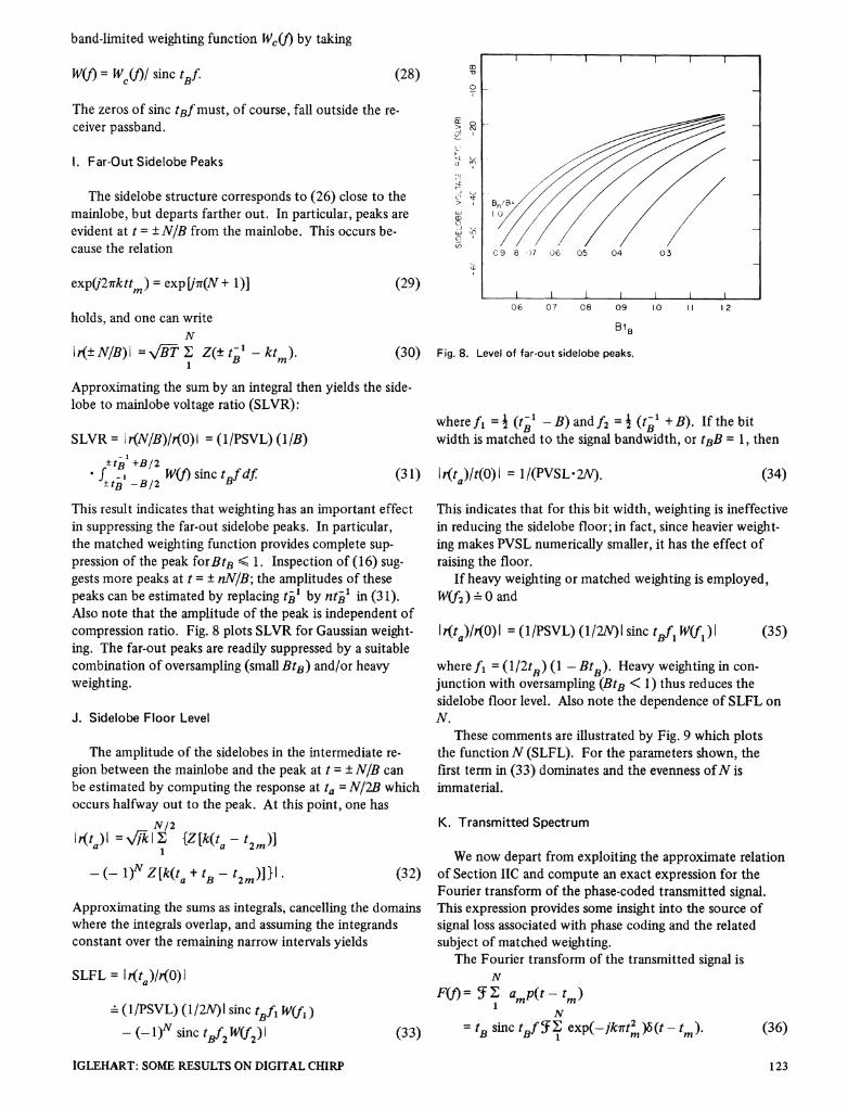
This result indicates that weighting has an important effectin suppressing the far-out sidelobe peaks. In particular,the matched weighting function provides complete sup-pression of the peak forBtB < 1. Inspection of (16) sug-gests more peaks at t = ± nN/B; the amplitudes of thesepeaks can be estimated by replacing tB1 by ntB1 in (31).Also note that the amplitude of the peak is independent ofcompression ratio. Fig. 8 plots SLVR for Gaussian weight-ing. The far-out peaks are readily suppressed by a suitablecombination of oversampling (small BtB) and/or heavyweighting.
J. Sidelobe Floor Level
The amplitude of the sidelobes in the intermediate re-gion between the mainlobe and the peak at t = ± N/B canbe estimated by computing the response at ta = N/2B whichoccurs halfway out to the peak. At this point, one has
N/2r{t ) = WlFk I{Z [k(t-a t2m)]- (-1 )N Z[k(ta + tB -t2m )]} - (32)
Approximating the sums as integrals, cancelling the domainswhere the integrals overlap, and assuming the integrandsconstant over the remaining narrow intervals yields
SLFL = I (ta)/r(O)_ (1/PSVL) (1/2N)I sinc tBfl W(f1 )
_ (- I)N sinc tBf2 W(f2) (33)
1-
Bn~~~~~~~/
C 9 8 -)7 06 05 04 03
IL IW I L06 07 08 09
BtB
1.0 1.1 1-2
Fig. 8. Level of far-out sidelobe peaks.
where fi = i (t-1 - B) and f2 = i (tB' + B). If the bitwidth is matched to the signal bandwidth, or tBB = 1, then
Ir(ta)/t(O)I = 1/(PVSL*2N). (34)
This indicates that for this bit width, weighting is ineffectivein reducing the sidelobe floor; in fact, since heavier weight-ing makes PVSL numerically smaller, it has the effect ofraising the floor.
If heavy weighting or matched weighting is employed,Wf2) _ O and
Ir(ta)/r(O)I = (1/PSVL) (1/2N)I sinc tBfi W(f1)I (35)
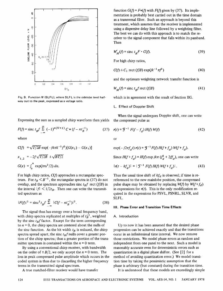
where f1 = (12tB) (1 -BtB). Heavy weighting in con-junction with oversampling (BtB < 1) thus reduces thesidelobe floor level. Also note the dependence of SLFL onN.
These comments are illustrated by Fig. 9 which plotsthe functionN (SLFL). For the parameters shown, thefirst term in (33) dominates and the evenness ofN isimmaterial.
K. Transmitted Spectrum
We now depart from exploiting the approximate relationof Section IIC and compute an exact expression for theFourier transform of the phase-coded transmitted signal.This expression provides some insight into the source ofsignal loss associated with phase coding and the relatedsubject of matched weighting.
The Fourier transform of the transmitted signal isN
F(f)= 5f I amp(t-tm)1
N= tB sinc tBf 5:Eexp(-jkirt' ff(t -tm ) (36)
IGLEHART: SOME RESULTS ON DIGITAL CHIRP 123
0
zx
N
-J
a)LJ
0
1
0 02 04 06 08 I0 2
EB
Fig. 9. Function N (SLFL), where SLFL is the sidelobe level half-way out to the peak, expressed as a voltage ratio.
Expressing the sum as a sampled chirp waveform then yields00
F(f =sinctBf z ( 1)n(N+l)C*(f-nt1)
where
Cf) =VT71exp(-jk7rk-'f2)[G(x2) -G(x1)
function G(f) = F*(f) with F(f) given by (37). Its imple-mentation is probably best carried out in the time domainas a transversal filter. Such an approach is beyond thistreatment, which assumes that the receiver is implementedusing a dispersive delay line followed by a weighting filter.The best we can do with this approach is to match the re-ceiver to the signal component that falls within its passband.Then
fV(j) = sinc tBF * C(f). (39)
For high chirp ratios,
C(f) - C1 rect (f/B) exp(klC 7rf2) (40)
and the optimum weighting network transfer function is
WM(Q) = sinc tBf rect (f/B) (41)
which is in agreement with the result of Section IIG.
L. Effect of Doppler Shift
When the signal undergoes Doppler shift, one can writethe compressed pulse as
(42)(37) -(t) = 5 - 1 F(f fd) H(Y) W(f)
or
exp(- i2ffdt) r(t) = 1 F(f)H(f+ fd) W(f+ fd).
x = -2fVTB +BT/2
G(x) = f exp t2 /2) dut.
For high chirp ratios, C(f) approaches a rectangular spec-
trum. For tB <B-1 , the rectangular spectra in (37) do notoverlap, and the spectrum approaches sinc tBf rect (f/B) inthe interval Ifl < 1I2tB. Then one can write the transmit-ted spectrum as
00
| )I= sinc tBf I C(f- ntB)1_ 00
(38)
The signal thus has energy over a broad frequency band,with chirp spectra replicated at multiples of tB1, weightedby the sinc tBf factor. Except for the term correspondingto n = 0, the chirp spectra are centered about the nulls ofthe sinc function. As the bit width tB is reduced, the chirpspectra spread apart; the sinc tBf nulls cover a greater por-
tion of the chirp spectra; thus a greater portion of the trans-mitter spectrum is contained within the n = 0 term.
By using a conventional chirp receiver, with bandwidthon the order of ± B/2, we only accept the n = 0 term. Theloss in peak compressed pulse amplitude which occurs in thecoded system is thus due to discarding the higher frequencyterms in the transmitted signal spectrum.A true matched-filter receiver would have transfer
Since H(f+ fd) = H(f) exp jkr (td + 2ffd), one can write
l1t- kfd)I = f-' FH(f)WH ffd). (43)
Thus the usual time shift of kfd is observed; if time is re-
referenced to the new mainlobe position, the compressedpulse shape may be obtained by replacing W(f) by W(f+fd)in expressions for r(t). This is the only modification re-
quired in the expressions for PSVL, PSNRL, SLVR, andSLFL.
111. Phase Error and Transition Time Effects
A. Introduction
Up to now it has been assumed that the desired phaseprogression can be achieved exactly and that the transitionsoccur in an infinitesimal time interval. We now remove
those restrictions. We model phase errors as random andindependent from one panel to the next. Such a model isreasonably accurate even for deterministic errors such as
quantization in a digital phase shifter. (See [2] for a
method of avoiding quantization error.) We model transi-tion time by taking the pessimistic assumption that thephase is arbitrary (but constant) during the transition time.
It is understood that these models are exceedingly simple
IEEE TRANSACTIONS ON AEROSPACE AND ELECTRONIC SYSTEMS VOL. AES-14, NO. 1 JANUARY 1978
Bn/B 07-
I I~~~~~~~~~~~~~~~~~~~~~~
0O
124
and probably do not reflect a given coder meChanizationvery accurately. Nonetheless, they provide some insight intothe nature of the error effects.
The derivations are performed for zero Doppler; modifi-cation to account for Doppler shift follows the reasoning ofSection II L and consists of replacing Wf) by W(f+ fd).
B. Phase Errors
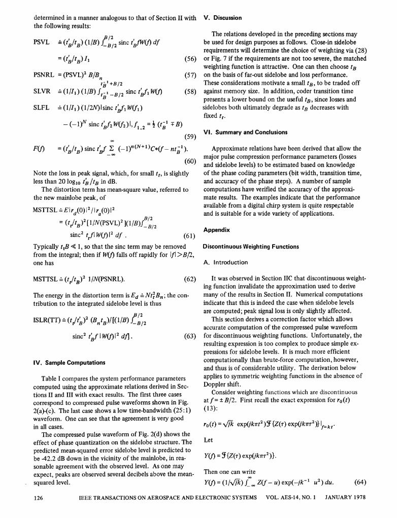
We assume that the phase shift of the mth panel (Am isgiven by Okm = 'om + em, where '° is the desired phaseshift, and em is a zero mean random variable with probabil-ity density function Pe(E), with variance a2, and with emindependent of e,n, m # n. Then one can write the mean-squared compressed pulse as
Elr(t)12 = 1y12 Ir (t)12 + (I -y12)Ird(t)12
0 0.2 0.4 0.6 08 10 12 14
BtB
Fig. 10. Plot of function used to compute mean-square error side-lobe level, in vicinity of mainlobe, due to error in phase progression.Gaussian weighting assumed.
ma
0
10
0
m
10
-o- O~o \
(44)
where rQ(t) is the compressed pulse in the absence of phaseerrors,
=tkt+B/2
ICtfIW()1df45ird(t) 12tB fkt-B/2 sinc" tBflW(f) d
and
(46)
For a uniform density of width q (the "quantization inter-val"),
00
ISLR(O) _Ed/Eu = BtB(1f sinc2 tBfI W(f) 2 df/
B/2 sinc2 tBflW(f)12 df
(47) and if the weighting function falls off rapidly for lfl > B/2,
For arbitrary density with a2 < 1, one has
12 = 2 (48)
with a' = q2/12 for the uniform density. The error effectsare thus twofold. A loss in peak signal of 10 log10 ky12 dBis incurred, and a distortion term appears. The latter isdispersed over a broad time interval; its mean-squaredamplitude relative to the mainlobe peak is, for a'2 < 1,
MSESL N(SVL)2 ](1/B) f_B12sinc)2 W(f)Idf
(49)
Note the dependence on N. Its total energy is
00
EdNBl-1712 sn2tBfl W(t) 12 df (50)
Consideration of the transmitted spectrum reveals thatfor large chirp ratios and tB <B-, the undistorted com-
pressed pulse has energy
= (T/B)f B/2 sinc2 tBfl W(I)12 df
ISLR(O) = Bt02 .B
C. Transition Times
Here we assume that, during the transition times, thetransmitted phase is constant, uniformly distributed over
[0, 27r] , and independent of the desired phase shifts andfrom one transition to the next. Then the transmitted pulsecan be written
N
f(t) = exp(jf ) p(t-tm; tB)
N
+ exp(Iem) p(t-tm -tB/2; tt)
(54)= fa(t) + fd(t)
where tt is the transition time, tg = tB - tt, and tm = (m(N + 1)/2) tB is as before; Em is a uniformly distributedrandom variable with Em independent of En, n A m. Thecompressed pulse may then also be written
(51)
it) ra(t) + rd(t)
The contribution of the distortion term to the integratedsidelobe ratio is, then, for u2 << 1,
(55)
with ra(t) a modified version of the desired waveform andrd(t) a distortion term. The features of ra(t) can be
(53)
IGLEHART: SOME RESULTS ON DIGITAL CHIRP
I I I I
Bn/B=090,80706
05
-\ 0 ~~4
032
_ MSESL= NT f(BtB)N I
y = fp.(x) exp(]x) dx.
,y 12= [(sin(q/2)/(q/2)]2.
(52)
0I
FC\M
f)r,
125
determined in a manner analogous to that of Section II withthe following results:
PSVL (IIt/B1B) IB/2 sinc tBA/fW) df
=(tB11tB) I' (5 6)
PSNRL = (PSVL)2 B/Bn (57)t1 +B/2
SLVR _(/)(1BStX B2sinc t>f1 WO (58)
SLFL (1/I1) (1/2N)I sinc tVfi W(fj)
-(-1)N sinc tf2W(f2)I,fl,2 = i(tGl TB)(59)
F(f) = (tb/tB) sinc tBf Z (_l)n(N+)C*(f - ntB').(61
Note the loss in peak signal, which, for small tt, is slightlyless than 20 log1o 4? /tB in dB.
The distortion term has mean-square value, referred tothe new mainlobe peak, of
MSTTSL -Eird(0)12/lra(0)12= (tYtB)2 [1/N(PSVL)2 ](J/B)f B/2
sinc2 ttfl W() 12 df.
V. Discussion
The relations developed in the preceding sections maybe used for design purposes as follows. Close-in sideloberequirements will determine the choice of weighting via (28)or Fig. 7 if the requirements are not too severe, the matchedweighting function is attractive. One can then choose tBon the basis of far-out sidelobe and loss performance.These considerations motivate a small tB, to be traded offagainst memory size. In addition, coder transition timepresents a lower bound on the useful tB, since losses andsidelobes both ultimately degrade as tB decreases withfixed tt.
VI. Summary and Conclusions
Approximate relations have been derived that allow themajor pulse compression performance parameters (losses
0) and sidelobe levels) to be estimated based on knowledgeof the phase coding parameters (bit width, transition time,and accuracy of the phase steps). A number of samplecomputations have verified the accuracy of the approxi-mate results. The examples indicate that the performanceavailable from a digital chirp system is quite respeptableand is suitable for a wide variety of applications.
(61)Typically ttB < 1, so that the sinc term may be removedfrom the integral; then if W(f) falls off rapidly for Ifl >B/2,one has
Appendix
Discontinuous Weighting Functions
A. Introduction
MSTTSL _(tt/tB)2 1/N(PSNRL). (62'
The energy in the distortion term is Ed - NttBn; the con-tribution to the integrated sidelobe level is thus
ISLR(TT)= (ti/tB)2 (BftB)I((lIB) B/2
sinc2 tBf I W(f)2 df. (63,
IV. Sample Computations
Table I compares the system performance parameterscomputed using the approximate relations derived in Sec-tions II and III with exact results. The first three casescorrespond to compressed pulse waveforms shown in Fig.2(a)-(c). The last case shows a low time-bandwidth (25:1)waveform. One can see that the agreement is very goodin all cases.
The compressed pulse waveform of Fig. 2(d) shows theeffect of phase quantization on the sidelobe structure. Thepredicted mean-squared error sidelobe level is predicted tobe 42.2 dB down in the vicinity of the mainlobe, in rea-sonable agreement with the observed level. As one mayexpect, peaks are observed several decibels above the mean-
squared level.
It was observed in Section IIC that discontinuous weight-ing function invalidate the approximation used to derivemany of the results in Section II. Numerical computationsindicate that this is indeed the case when sidelobe levelsare computed; peak signal loss is only slightly affected.
This section derives a correction factor which allowsaccurate computation of the compressed pulse waveformfor discontinuous weighting functions. Unfortunately, theresulting expression is too complex to produce simple ex-pressions for sidelobe levels. It is much more efficientcomputationally than brute-force computation, however,and thus is of considerable utility. The derivation belowapplies to symmetric weighting functions in the absence ofDoppler shift.
Consider weighting functions wlhich are discontinuousat f = ± B/2. First recall the exact expression for ro(t)(13):
ro(t) = v'Jki exp(kart2) SF{Z(r) exp(Qk7rr2 )} f=k t'
Let
Y(J) = f{Z(r) expik7Trr2)}.
Then one can write
Y(t) = (1/VFk) J. Z(f- u) exp(-jk-l U2) du. (64)
IEEE TRANSACTIONS ON AEROSPACE AND ELECTRONIC SYSTEMS VOL. AES-14, NO. 1 JANUARY 1978
00
126
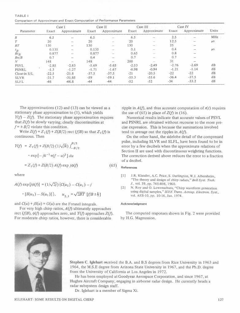
TABLE IComparison of Approximate and Exact Computation of Performance Parameters
Case I Case II Case III Case IVParameter Exact Approximnate Exact Approximate Exact Approximate Exact Approximate Units
B 6.5 - 6.5 - 6.5 - 2.5 - MHzT 20 - 20 - 20 - 12.5 - ,sBT 130 - 130 - 130 - 25 -tB 0.135 - 0.135 - 0.1 - 0.4 - AsBtB 0.877 - 0.877 - 0.65 - 0.8 -Bn/B 0.7 - 0.4 - 0.7 - 0.7 -
N 148 - 148 - 200 - 31 -PSVL -2.85 -2.83 -5.69 -5.65 -2.53 -2.49 -2.76 -2.69 dBPSNRL -1.3 -1.27 -1.71 -1.67 -0.98 -0.94 -1.21 -1.14 dBClose-in S/L -22.5 -21.8 -37.5 -37.5 -21 -20.5 -22 -22 dBSLVR -31.7 -31.85 -59 -59.1 -55.3 -55.6 -36.4 -37.5 dBSLFL -46 -46.8 -44 -44 -52 -52 -34 -33.2 dB
The approximations (12) and (13) can be viewed as astationary phase approximation to (1), which yieldsY(f) - Z(t). The stationary phase approximation requiresthat Z(f) be slowly varying; clearly discontinuities atf= ± B/2 violate this condition.
Write Z(f) = Z1 (t) + Z(B/2) rect (f/B) so that Z1 (t) iscontinuous. Then
= ~ ~ (,V-B/2YUt) = Zlf)+Z(B/2)(lIk) B/2
* exp [-jik- T(f U)21 du= Z1 (f) + Z(B/2)A (f) exp jO(t) (65)
where
A(f) exp[jp(f)] = (I/)j C(U2)-= U )-j
* [S(U2)- AU0)]}, U2,1 = 2T Lf/B±1]and C(u) + jS(u) = G(u) are the Fresnel integrals.
For very high chirp ratios, A(f) ultimately approachesrect (f/B), 0(t) approaches zero, and Y(t) approaches Z(f).For moderate chirp ratios, however, there is considerable
ripple in A(t), and thus accurate computation of r(t) requiresthe use of (65) in place ofZ(f) in (16).
Numerical results indicate that accurate values ofPSVLand PSNRL are obtained without recourse to the more pre-cise expression. This is because the summations involvedtend to average out the ripples inA(f).
On the other hand, the sidelobe detail of the compressedpulse, including SLVR and SLFL, have been found to be inerror by a few decibels when the approximate relations ofSection II are used with discontinuous weighting functions.The correction derived above reduces the error to a fractionof a decibel.
References
[11 J.R. Klauder, A.C. Price, S. Darlington, W.J. Albersheim,"The theory and design of chirp radars," Bell Syst. Tech.J., vol. 39, pp. 745-808, 1960.
[2] N. Roy and 0. Lowenschuss, "Chirp waveform generationusing digital samples," IEEE Trans. A erosp. Electron. Syst.,vol. AES-10, pp. 10-16, Jan. 1974.
Acknowledgment
The computed responses shown in Fig. 2 were providedby H.G. Magnussion.
Stephen C. Iglehart received the B.A. and B.S degrees from Rice University in 1963 and1964, the M.S.E degree from Arizona State University in 1967, and the Ph.D. degreefrom the University of California at Los Angeles in 1972.
He has been employed at Goodyear Aerospace Corporation, and since 1967, atHughes Aircraft Company, engaging in airborne radar design. He currently heads aradar subsystem design staff.
Dr. Iglehart is a member of Sigma Xi.
IGLEHART: SOME RESULTS ON DIGITAL CHIRP 127