solving spillway geometry for three-dimensional flow · the ogee profile continued throughout the...
TRANSCRIPT

Solving spillway geometry for three-dimensional flow
G.L. Coetzee University of Pretoria, Pretoria, The Republic of South Africa
Knight Piésold Consulting, Keetmanshoop, The Republic of Namibia
S.J. van Vuuren University of Pretoria, Pretoria, The Republic of South Africa
ABSTRACT: The Ogee profile is one of the most studied hydraulic relationships used in the de-sign of spillways. The high discharge efficiency and nappe-shaped profile ensure an effective hydraulic system, if applied under the correct conditions. However, in a recent study, the exist-ing Ogee profile relationship, formulated for two-dimensional flow conditions, proved to be in-sufficient for three-dimensional flow conditions. Data obtained from a detailed physical model study and extensive computational fluid dynamic simulations allowed for a qualitative and quantitative comparison of the bottom nappe of the fluid profile across an aerated sharp-crested weir. The study concluded in the derivation of the VC-Ogee relationship that estimates the Ogee profile under three-dimensional flow conditions. Four parameters A, B, C and D, were incorpo-rated to accommodate the effect of three-dimensional flow. A set of VC-Ogee design curves for these parameters, for an asymmetrical approach channel with side contraction of the spillway, is presented in this paper. Further design curves to accommodate symmetrical, contracted and un-contracted approach channels as well as combinations of these conditions, will be made availa-ble in future.
RÉSUMÉ: Le profil Ogee est l’une des relations hydrauliques les plus étudiées dans la concep-tion des déversoirs. La haute efficacité d’écoulement et le profil en forme de nappe assurent un système hydraulique efficace s’il est appliqué dans les conditions appropriées. Cependant, dans une étude récente, la relation de profil Ogee existante, formulée pour des conditions d’écoulement bidimensionnelles, s’est avérée insuffisante pour des conditions d’écoulement tri-dimensionnelles. Les données obtenues à partir d’une étude de modèle physique détaillée et de simulations informatiques exhaustives de la dynamique des fluides ont permis une comparaison qualitative et quantitative de la nappe inférieure du profil de fluide à travers un déversoir élevé à crête pointue aéré. Ces études ont permis de dériver la relation « Ogee VC » qui comprend des déversoirs droits et courbes, des canaux d’approche symétriques et asymétriques, ainsi que des déversoirs contractés et non contractés. Quatre paramètres A, B, C et D ont été incorporés pour tenir compte de l’effet du débit tridimensionnel. Cet article présente un ensemble de courbes de conception VC-Ogee pour ces paramètres, pour un canal d'approche asymétrique avec contrac-tion latérale du déversoir. D'autres courbes de conception permettant d'adapter des canaux d'ap-proche symétriques, contractés et non contractés, ainsi que des combinaisons de ces conditions, seront disponibles à l'avenir.

1 INTRODUCTION
The Ogee profile is one of the most studied hydraulic relationships used for the design of spill-ways throughout the world (Savage & Johnson, 2001). Advances of the relationship to describe the Ogee profile continued throughout the 20th century by means of physical modelling and ap-plying empirical and mathematical relations to approximate the profile. The Ogee profile is used for spillway design because it minimises the occurrence of sub-atmospheric pressures forming on the surface of the spillway.
The original approximation of the profile was determined by the first principles of projectile movement (Chow, 1959). The trajectory of the lower nappe for an aerated free-falling jet of wa-ter flowing over a sharp-crested weir (SCW) was determined. Many improvements and altera-tions were incorporated since the original trajectory’s formula had been determined.
Unfortunately, these numerical relationships only considered two-dimensional flow charac-teristics of the approach channel, namely: the available energy (i.e. depth and velocity of water flowing over the spillway crest); the angle of inclination of the upstream wall face; and the height of the spillway above the natural ground level (pool depth).
When considering an Ogee spillway, designed using a two-dimensional flow relationship with an asymmetrical and/or oblique approach channel, three-dimensional flow across the Ogee spillway will be present (Coetzee, 2012). If the flow rate is further increased, a sub-atmospheric pressure region is generated that could lead to cavitation (Momber, 2000; Savage & Johnson, 2001). Cavitation on the spillway may occur when hydrostatic pressure on the surface of the spillway reduces to sub-atmospheric pressure, normally at regions along the spillway where the unit discharge is a maximum. The long-term exposure to extensive sub-atmospheric conditions may cause failure of the spillway structure.
2 ADAPTATIONS REQUIRED FOR THE OGEE SPILLWAY RELATIONSHIP TO ACCOMMODATE THREE-DIMENSIONAL FLOW
The current design relationships for Ogee spillways were derived with the assumption that only two-dimensional, parallel flow conditions are present in the upstream approach channel. Three-dimensional flow upstream of a spillway causes separation of the lower nappe of water flowing over the spillway, adversely influencing the pressure distribution on the crest of the spillway. Sub-atmospheric pressures on the surface of the spillway may cause cavitation and spillway erosion. Catastrophic failure of the structure may occur during high flood events if these three-dimensional flow parameters are not given due consideration during the design of the spillway.
In 2011 Van Vuuren et al. postulated that, based on the observations made from the physical modeling of the Neckartal Dam (constructed in the Fish River, Namibia), three-dimensional flow conditions should be incorporated in the design of Ogee spillways. It was conjectured that the following parameters influence the Ogee relationship as well as the unit discharge:
• the symmetry of the upstream approach channel;
• the orientation of the spillway and dam wall relative to the direction of flow in
the upstream approach channel; and
• the radius/curvature of the dam wall and spillway. In 2012, Coetzee confirmed the hypothesis of Van Vuuren et al. (2011), concluding that the
symmetry of the upstream approach channel and the orientation of flow relative to the spillway, do indeed influence the shape of the Ogee profile. Van Vuuren and Coetzee (2015) then under-took a study with the Water Research Commission (WRC) of South Africa to investigate the ef-fects of three-dimensional flow caused by asymmetry of the upstream approach channel and curvature of the dam wall. Experimental tests were conducted on a sharp-crested weir (SCW) (ISO 1438, 2008) for which the lower nappe, known as the Ogee profile, was measured. The measured profiles were compared to the various relationships currently available in literature, namely: Chow (1959); Knapp, et al. (1970); Melsheimer & Murphy (1970); Ministry of Science and Technology (2007); Murphy (1973); USACE (a) (1987); USACE (b) (1987); USBR (1987); Wahl, et al. (2008); Hager (1987).

A baseline/symmetrical approach channel was modelled physically and numerically using Next Limit’s XFlow and CD-Adapco’s STAR-CCM+ Computational Fluid Dynamics (CFD) software. The assessment compared the results of the CFD modeling with the results obtained from the physical model research. With the required numerical refinements and mesh independ-ence studies, the numerical results were found to be within the equitable accuracy of the physi-cal model (Van Vuuren & Coetzee, 2015a; 2015b).
These findings indicated the need to include three-dimensional flow parameters for the nu-merical approximation of the Ogee profile and reflected the shortcomings of the current mathe-matical relationships used for the design of conventional Ogee spillways. A new numerical rela-tionship for the Ogee profile was subsequently developed to include the upstream flow parameters that contribute to three-dimensional flow and was referred to as the VC-Ogee rela-tionship derived from the surnames of Van Vuuren and Coetzee (Van Vuuren & Coetzee, 2016). The new relationship improves the Ogee profile’s geometry, resulting in a significantly more ef-fective and safer dam wall.
3 THE DERIVATION OF THE NEW VC-OGEE RELATIONSHIP
The development of the VC-Ogee relationship was based on the relationships by Hager (1987) for the upstream quadrant, and the WES procedure for the downstream quadrant of the Ogee profile (USBR, 1987). These relationships were extended to incorporate the three-dimensional flow conditions referred to above.
Hager (1987) had derived a relationship for a continuous Ogee profile based on the com-
pound curve formulation by the USBR (Chapter 9: Spillways, 1987). A continuous profile,
without any abrupt changes in curvature, ensures that breakaway from the surface of the spill-
way is prevented, thereby ensuring a safer spillway design. The relationship by Hager (Equa-
tion 1) utilises a unitised coordinate system, viz.; X=x
He and Z=
z
He . The variables for the VC-
Ogee relationship are defined in Figure 1.
Figure 1. Definition sketch of VC-Ogee relationship
The relationship by Hager:
Z*= -X* ln X* valid for X*>-0.2818 (1)
with
X*= 1.3055∙(X+0.2818) (2) and
Z*= 2.7050∙(Z+0.1360) (3)

Using substitution, Equation 1 is re-written in the format shown in Equation 4.
z = -He((1.3055∙(
x
He+0.2818)∙ ln(1.3055∙(
x
He+0.2818))
2.7050) +0.1360) (4)
By combing constants, re-arranging and applying mathematical manipulation by dividing
with Euler's number (e), Equation 5 was obtained. The objective was to derive a relationship which contains parameters that can be used to change the ordinates of the Ogee geometry in the vertical and horizontal directions, independently.
z = -He∙B((x
He∙A+
1
e) ∙ ln (
x
He∙A+
1
e)+
1
e) (5)
The coefficients A and B are used to alter the horizontal and vertical geometry of the Ogee
profile, respectively. The default values of these coefficients in the VC-relationship, to duplicate
the Ogee profile suggested by Hager, are A = 0.766 and B = 0.3697. Equation 5 accommodates
the definition of the vertical asymptote (the start of the VC-Ogee’s upstream quadrant profile)
by the inclusion of the term ln (x
He∙A+
1
e) > 0. Depending on the slope of the upstream wall, this
term may be used to determine a tangent point on the upstream side of the Ogee profile. A
smoother transfer of the curvature from the upstream wall to the Ogee profile is thus achieved.
To independently modify the up- and downstream quadrants of the VC-Ogee profile, a sec-
ond equation was investigated. To ensure a smooth, uniform transfer of the curvature, without
any discontinuities, the upstream and downstream quadrants had to intercept at dz
dx = 0. The
downstream quadrant of the Ogee profile was defined by using a modified version of the WES
power function (Equation 6). This was similar to the approach followed by the USBR (1987)
and USACE (1970).
z =xC
D∙He(C-1) (6)
The default values of these coefficients in the VC-Ogee relationship, to duplicate the two-
dimensional Ogee profile, suggested by USBR (1987), are C = 1.85 and D = 2. Depending on the extent of the three-dimensional flow, the values of C and D must be changed. The coeffi-cient C can be used to adjust the curvature of the downstream quadrant, while D defines the magnitude of the profile.
The proposed VC-Ogee relationship, in Macaulay notation, is reflected in Equation 7.
VC-Ogee=
{
z = -He∙B((x
He∙A+
1
e) ∙ ln (
x
He∙A+
1
e)+
1
e) for the upstream quadrant
z =xC
D∙He(C-1) for the downstream quadrant
(7) The four parameters A, B, C and D in Equation 7, denotes the horizontal spread (A), vertical
elongation (B), curvature (bulging effect) (C) and magnitude (D) of the Ogee profile and were adjusted to find the best fit. The exaggerated illustrations of the influence of the different pa-rameters were shown in Table 1. Optimal selection of the parameters A, B, C, and D ensures a functional spillway profile and preventing breakaway during three-dimensional flow conditions.
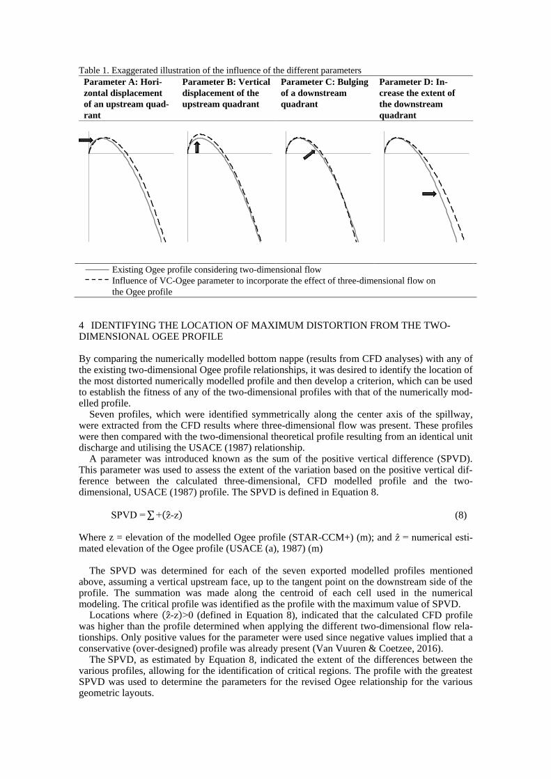
Table 1. Exaggerated illustration of the influence of the different parameters
Parameter A: Hori-
zontal displacement
of an upstream quad-
rant
Parameter B: Vertical
displacement of the
upstream quadrant
Parameter C: Bulging
of a downstream
quadrant
Parameter D: In-
crease the extent of
the downstream
quadrant
Existing Ogee profile considering two-dimensional flow
Influence of VC-Ogee parameter to incorporate the effect of three-dimensional flow on
the Ogee profile
4 IDENTIFYING THE LOCATION OF MAXIMUM DISTORTION FROM THE TWO-DIMENSIONAL OGEE PROFILE
By comparing the numerically modelled bottom nappe (results from CFD analyses) with any of the existing two-dimensional Ogee profile relationships, it was desired to identify the location of the most distorted numerically modelled profile and then develop a criterion, which can be used to establish the fitness of any of the two-dimensional profiles with that of the numerically mod-elled profile.
Seven profiles, which were identified symmetrically along the center axis of the spillway, were extracted from the CFD results where three-dimensional flow was present. These profiles were then compared with the two-dimensional theoretical profile resulting from an identical unit discharge and utilising the USACE (1987) relationship.
A parameter was introduced known as the sum of the positive vertical difference (SPVD). This parameter was used to assess the extent of the variation based on the positive vertical dif-ference between the calculated three-dimensional, CFD modelled profile and the two-dimensional, USACE (1987) profile. The SPVD is defined in Equation 8.
SPVD =∑+(z-z) (8)
Where z = elevation of the modelled Ogee profile (STAR-CCM+) (m); and ẑ = numerical esti-mated elevation of the Ogee profile (USACE (a), 1987) (m)
The SPVD was determined for each of the seven exported modelled profiles mentioned above, assuming a vertical upstream face, up to the tangent point on the downstream side of the profile. The summation was made along the centroid of each cell used in the numerical modeling. The critical profile was identified as the profile with the maximum value of SPVD.
Locations where (z-z)>0 (defined in Equation 8), indicated that the calculated CFD profile was higher than the profile determined when applying the different two-dimensional flow rela-tionships. Only positive values for the parameter were used since negative values implied that a conservative (over-designed) profile was already present (Van Vuuren & Coetzee, 2016).
The SPVD, as estimated by Equation 8, indicated the extent of the differences between the various profiles, allowing for the identification of critical regions. The profile with the greatest SPVD was used to determine the parameters for the revised Ogee relationship for the various geometric layouts.

A threshold value, SPVD/He, was introduced for the comparison of the fitness of the Ogee-relationship with the CFD modelled profile. Van Vuuren and Coetzee (2016) initially recom-mended a threshold of 1%, which resulted in some cases to the over-designing of the Ogee pro-file. Subsequently the criteria, SPVD/He, was relaxed to ≈< 5%. The vertical difference of the Ogee profiles is illustrated in Figure 2.
Figure 2. Definition of the vertical difference of the Ogee profiles
The formal design curves for a contracted, asymmetrical approach channel, with a straight
weir for the VC-Ogee relationship are discussed below.
5 CONTRACTED ASYMMETRICAL APPROACH CHANNEL WITH A STRAIGHT WEIR
The typical layout for a contracted asymmetrical approach channel with a straight weir is shown in Figure 3.
Figure 3. Typical layout of a contracted asymmetrical approach channel with a straight weir
The calculated parameters (A, B, C & D) for contracted asymmetrical approach channels with
straight weirs were also split into two groups namely, layouts with P/Hd < 6, and layouts with P/Hd ≥ 6 where Hd is defined as the design head (m) equivalent to the total energy head, He, de-picted in Figure 1; and P is the upstream pool depth (m). The inclination of the sidewall influ-ences the contraction of flow for asymmetrical approach channels. The results obtained from the different layouts were applied to calculate contour plots that can be used as design curves for
Description Notation Status
Permanent Cannel - - Adjustable side wall C ✓ Inclination of the side wall
BB° 45°, 60° & 90°
Crest of the SCW - Straight weir Angle of approach chan-nel
EE.EE° 0° → 25°
Adjustable side wall C ✓

contracted, asymmetrical approach channels, with straight weirs, as depicted in Figure 4, for layouts with P/Hd < 6, and in Figure 5 for layouts with P/Hd ≥ 6. To apply these design curves effectively to new Ogee spillway designs, the inclination of the sidewalls and the angle of flow in the approach channel (vertical axis) must be known (measured in degrees). The intercept of these two values gives the unknown parameters A, B, C or D to be used as input values for the VC-Ogee relationship.
Figure 4. Design curves for symmetrical, contracted approach channels with straight weirs for layouts
with P/Hd < 6 (AS-CO-S – P/Hd < 6)
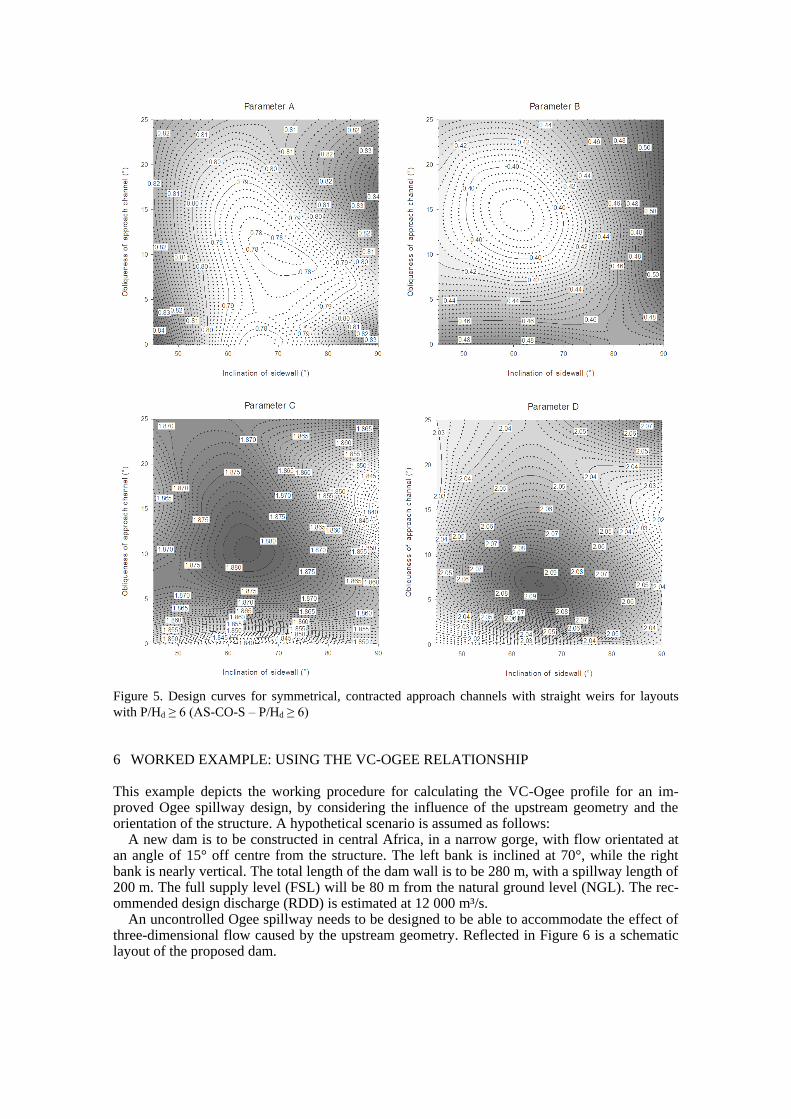
Figure 5. Design curves for symmetrical, contracted approach channels with straight weirs for layouts
with P/Hd ≥ 6 (AS-CO-S – P/Hd ≥ 6)
6 WORKED EXAMPLE: USING THE VC-OGEE RELATIONSHIP
This example depicts the working procedure for calculating the VC-Ogee profile for an im-proved Ogee spillway design, by considering the influence of the upstream geometry and the orientation of the structure. A hypothetical scenario is assumed as follows:
A new dam is to be constructed in central Africa, in a narrow gorge, with flow orientated at an angle of 15° off centre from the structure. The left bank is inclined at 70°, while the right bank is nearly vertical. The total length of the dam wall is to be 280 m, with a spillway length of 200 m. The full supply level (FSL) will be 80 m from the natural ground level (NGL). The rec-ommended design discharge (RDD) is estimated at 12 000 m³/s.
An uncontrolled Ogee spillway needs to be designed to be able to accommodate the effect of three-dimensional flow caused by the upstream geometry. Reflected in Figure 6 is a schematic layout of the proposed dam.

Figure 6. Section view, with left and right bank, downstream isometric views of the worked example
Solution: Left bank inclination = 70° Right bank inclination = 90° Obliqueness of approach channel = 15° Upstream depth (P) = FSL – NGL = 80 m Unit discharge rate of spillway (Qogee) = 12 000 m³/s / 200 m = 60 m³/s/m Discharge calculation:
Qogee
= √2g∙Cd∙Hd
3
2 (9)
Assume P/Hd > 3 m/m Therefore, the discharge coefficient (USBR, 1987) can be calculated by:
Cd = 2
3∙√3∙ (1+
4
9+5)=0.495 (10)
Calculate the equivalent design head from Equation (9):
60 = √2∙9.81∙0.495∙Hd
32
Hd = (60
√2∙9.81∙0.495)
23
=9.081 m
Check the assumption P/Hd = 80/9.081 = 8.8 The assumption is acceptable; therefore, proceed to the design curves. The approach channel is asymmetrical, with an obliqueness of 15°. The P/Hd ratio is greater than 6. Thus, design curve AS-CO-S – P/Hd ≥ 6, as denoted in Figure 5 must be used.

Figure 5 (copy). Design curves for asymmetrical, contracted approach channels with straight weirs for
layouts with P/Hd ≥ 6 (AS-CO-S – P/Hd ≥ 6)
Interpolating from the contours the following parameter values are estimated (see figure above): Parameter A = 0.787 Parameter B = 0.402 Parameter C = 1.873 Parameter D = 2.057 Substitute the estimated parameter values into Equation 7, with the calculated design head, the Ogee profile may be plotted as shown in Figure 6.
Parameter A
= 0.787 Parameter B
= 0.402
Parameter C
= 1.873 Parameter D
= 2.057

VC-Ogee =
{
z = -Hd∙B((
x
Hd∙A+
1
e) ∙ ln (
x
Hd∙A+
1
e)+
1
e) for the upstream quadrant
z =xC
D∙Hd(C-1)
for the downstream quadrant
(7)
VC-Ogee =
{
z = -9.081∙0.402((
x
9.081∙0.787+
1
e) ∙ ln (
x
9.081∙0.787+
1
e)+
1
e)
z =x1.873
2.057∙9.081(1.873-1)
Figure 6 compares the VC-Ogee, USBR (1987) and USACE (1987) profiles for equivalent
design heads (Hd). Note that the VC-Ogee depicts a profile that is vertically and horizontally increased on the upstream side (the profile starts at a lower coordinate (-2,629 m; -1,343 m) compared to the two-dimensional relationships starting at approximately (-2,579 m; -1.153 m)). Similarly, on the downstream side, the overall size is increased. When plotted from the maxi-mum crest positions (0,000; 0,000), the offset in the vertical elevation, measured in millimeter, and along the horizontal axis, measured in meter, between the VC-Ogee relationship and USACE (1987) and USBR compound (1987) Ogee curve are depicted in Figure 7.
Figure 6. Calculated VC-Ogee profile as compared with USBR (1987) and USACE (1987)
Figure 7 demonstrates that the maximum offset between the VC-Ogee Relationship and the
two-dimensional Ogee relationships (USACE (1987) and USBR compound (1987)) are in the order of 50 mm, at the upstream quadrant. The vertical difference between the Ogee profiles increases to approximately 300 mm for the compound USBR (1987) relationship and 200 mm for the USACE (1987) relationship at the downstream quadrant. The abrupt change in curvature of the existing two-dimensional relationships can be observed by the undulations and offsets where arcs are joined together to make-up the Ogee profile. The VC-Ogee profile reduces pos-sible breakaway by excluding these arcs and by having a smooth curvature. This contributes to the overall safety of the design.
-20
-19
-18
-17
-16
-15
-14
-13
-12
-11
-10
-9
-8
-7
-6
-5
-4
-3
-2
-1
0
1
-5 -4 -3 -2 -1 0 1 2 3 4 5 6 7 8 9 10 11 12 13 14 15 16 17 18 19 20
Ele
va
tio
n, Z
(m
)
Horizontal distance, X (m)
VC-OGEE USBR (1987) USACE (1987)
-1.50
-1.25
-1.00
-0.75
-0.50
-0.25
0.00
0.25
0.50
-3.00 -2.00 -1.00 0.00 1.00 2.00 3.00 4.00
Ele
va
tion
, Z
(m
)
Horizontal distance, X (m)
Crest region
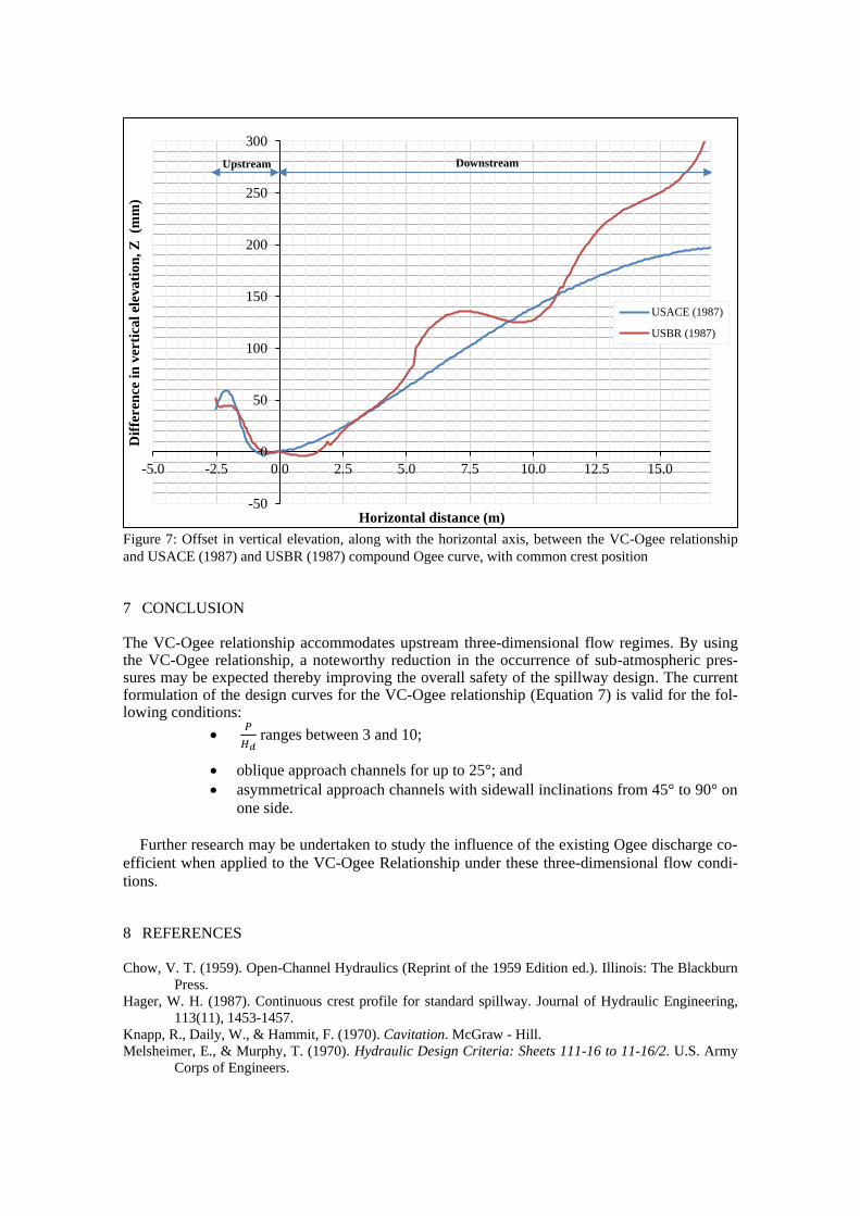
Figure 7: Offset in vertical elevation, along with the horizontal axis, between the VC-Ogee relationship
and USACE (1987) and USBR (1987) compound Ogee curve, with common crest position
7 CONCLUSION
The VC-Ogee relationship accommodates upstream three-dimensional flow regimes. By using the VC-Ogee relationship, a noteworthy reduction in the occurrence of sub-atmospheric pres-sures may be expected thereby improving the overall safety of the spillway design. The current formulation of the design curves for the VC-Ogee relationship (Equation 7) is valid for the fol-lowing conditions:
• 𝑃
𝐻𝑑 ranges between 3 and 10;
• oblique approach channels for up to 25°; and
• asymmetrical approach channels with sidewall inclinations from 45° to 90° on
one side.
Further research may be undertaken to study the influence of the existing Ogee discharge co-
efficient when applied to the VC-Ogee Relationship under these three-dimensional flow condi-
tions.
8 REFERENCES
Chow, V. T. (1959). Open-Channel Hydraulics (Reprint of the 1959 Edition ed.). Illinois: The Blackburn
Press.
Hager, W. H. (1987). Continuous crest profile for standard spillway. Journal of Hydraulic Engineering,
113(11), 1453-1457.
Knapp, R., Daily, W., & Hammit, F. (1970). Cavitation. McGraw - Hill.
Melsheimer, E., & Murphy, T. (1970). Hydraulic Design Criteria: Sheets 111-16 to 11-16/2. U.S. Army
Corps of Engineers.
-50
0
50
100
150
200
250
300
-5.0 -2.5 0.0 2.5 5.0 7.5 10.0 12.5 15.0
Dif
fere
nce
in
ver
tica
l el
eva
tio
n, Z
(m
m)
Horizontal distance (m)
USACE (1987)
USBR (1987)
Upstream Downstream

Ministry of Science and Technology. (2007). CE-05016 Design of Hydraulic Structures. Myanmar: De-
partment of Technical and Vocational Education. Retrieved July 18, 2012, from
http://www.most.gov.mm/techuni/media/CE_05016_ch1.pdf
Murphy, T. E. (1973). Spillway Crest Design. Vicksburg: US Army Engineer Waterways Experiment Sta-
tion.
USACE (a). (1987). Hydraulic Design Criteria: Overflow Spillway Crest. Vicksburg, Mississippi: U.S.
Army Engineers Waterways Experiment Station.
USACE (b). (1987). Hydraulic Design Criteria: Elliptical Crest Spillway Co-ordinates. Vicksburg, Mis-
sissippi: U.S. Army Engineer Waterways Experiment Station.
USACE. (1970). Hydraulic Design Criteria. Vicksburg, MI: Army Waterways Experiment Station.
USBR. (1987). Chapter 9: Spillways. In Design of Small Dams (3rd ed., pp. 339-434). Washington: U.S.
Government Printing Office.
Van Vuuren, S. J., & Coetzee, G. L. (2015). WRC Report No. 2253/1/15: Additional parameters for the
design of straight Ogee spillways. Pretoria: Water Research Commission. Retrieved from
www.wrc.org.za
Van Vuuren, S. J., & Coetzee, G. L. (2015a). Comparison between CFD analyses and physical modelling
of an Ogee profile. Dam safety, maintenance & rehabilitation of dams in Southern Africa. I, pp.
195-208. Cape Town, South Africa: SANCOLD.
Van Vuuren, S. J., & Coetzee, G. L. (2015b). Evaluation of the influence of 3-dimensional upstream flow
and geometric parameters when designing and Ogee spillway. Dam safety, maintenance & reha-
bilitation of dams in Southern Africa (pp. 209-222). Cape Town, South Africa: SANCOLD.
Van Vuuren, S. J., & Coetzee, G. L. (2016). The development of the VC-Ogee relation-ship which incor-
porates upstream 3-dimensional flow conditions. Sandton, Johannesburg: International Commis-
sion on Large Dams.
Wahl, T. L., Frizell, K. H., & Cohen, E. A. (2008). Computing the Trajectory of Free Jets. Journal of Hy-
draulic Engineering © ASCE, 10.1061(2), 256-260.