solution of nonlinear dynamic response-partii nonlinear dynamic response - part ii transparency 14-9...
TRANSCRIPT

Topic 14
Sections 9.3.1, 9.3.2, 9.3.3, 9.5.3, 8.2.4
9.6,9.7,9.8,9.11
Contents: •••••••••••
Mode superposition analysis in nonlinear dynamics
Substructuring in nonlinear dynamics, a schematicexample of a building on a flexible foundation
Study of analyses to demonstrate characteristics ofprocedures for nonlinear dynamic solutions
Example analysis: Wave propagation in a rod
Example analysis: Dynamic response of a three degree offreedom system using the central difference method
Example analysis: Ten-story tapered tower subjected toblast loading
Example analysis: Simple pendulum undergoing largedisplacements
Example analysis: Pipe whip solution
Example analysis: Control rod drive housing with lowersupport
Example analysis: Spherical cap under uniform pressureloading
Example analysis: Solution of fluid-structure interactionproblem
Solution ofNonlinearDynamicResponse-Part II
Textbook:
Examples:

14-2 Nonlinear Dynamic Response - Part II
References: The use of the nonlinear dynamic analysis techniques is described withexample solutions in
Bathe, K. J., "Finite Element Formulation, Modeling and Solution ofNonlinear Dynamic Problems," Chapter in Numerical Methodsjor Partial Differential Equations, (Parter, S. V., ed.), Academic Press, 1979.
Bathe, K. J., and S. Gracewski, "On Nonlinear Dynamic Analysis UsingSubstructuring and Mode Superposition," Computers & Structures, 13,699-707,1981.
Ishizaki, T., and K. J. Bathe, "On Finite Element Large Displacementand Elastic-Plastic Dynamic Analysis of Shell Structures," Computers& Structures, 12, 309-318, 1980.

TH E S OLV\T ION 0 F
TH E ']) 'YNAM Ie EQUlLJ B-
~IUH ElluATIONS CAN
'5£ ACHI£VE~ US1I'Jb
'DIR=,-T "I.NTE{;RATJON
Me-PtobS,
_ E,>£PL\C tT lNTE. 5R.
S~B'STR lACTu'R 11\15
w~ I)lSCUSS i~ESE l~H'
NIQuES ~'R'EFL'I I~ \t\\S
LEe.n,fi<.E
WAVE t'RO?A6A
IN A 1"01>
\Ex.,- 1':ESl'ONSE OF A
3 :).O.F. S'tS"TEP-1
\
E.)(,S ANAl.'1S1S OF
TE N ~To"R'I
IA'PE:'KEb TOWER
\
EX,4- AN!\L"ISI'i> O~
1>E N b\.A LtA M
\
EXS P\?E wlil?
'RES"PONS,c SOUA110N
Topic Fourteen 14-3
. A""AL't~IS OF CR.b
1-1011\'>11\1&
SOL-I.tTION OF "RE::C;?ONS~
OF S'PHE~llAL CAP
• At-IAL'ISI<;' OF FLU,J)
ST'RlA(.TI.t'RE III.1T~AC.:noN
"P1<:OJ3.LE t1 ('t:>1 i"E. lEST)
THE 1:>E:TAIL.'S, Of'
nlESE "?'R~~LEl'-\
S,bLuTICNc:. "~E
61\1E III 1 N THE
"f~'PE'RS SE.EI
STUb,! oLAlbE
Markerboard14-1

14-4 Nonlinear Dynamic Response - Part II
Transparency14-1
Mode superposition:
• The modes of vibration change due tothe nonlinearities, however we canemploy the modes at a particular timeas basis vectors (generalizeddisplacements) to express theresponse.
• This method is effective when, innonlinear analysis,
- the response lies in only a fewvibration modes (displacementpatterns)
- the system has only localnonlinearities
Transparency14-2
The governing equations in implicit timeintegration are (assuming no dampingmatrix)M HLltO(k) + TK ~U(k) = HLltR _ HLltF(k-1)- - -
Let now T = 0, hence the method ofsolution corresponds to the initial stressmethod.
Using
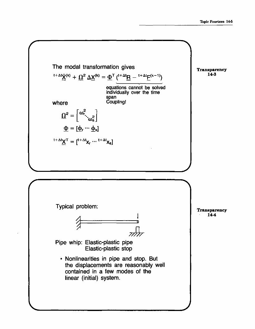
The modal transformation gives
H.:1tX(k) + 0 2 ax(k) = <I>T (H.:1tR _ H.:1tF(k-1»)
Topic Fourteen 14-5
Transparency14-3
where
n2 = [W~"W~]<I> = ~r ... ~s]
.equations cannot be solvedindividually over the timespanCoupling!
Typical problem:
~~========:::::::D!I~
Pipe whip: Elastic-plastic pipeElastic-plastic stop
• Nonlinearities in pipe and stop. Butthe displacements are reasonably wellcontained in a few modes of thelinear (initial) system.
Transparency14-4

1~ Nonlinear Dynamic Response - Part II
Transparency14-5
Substructuring
• Procedure is used with implicit timeintegration. All linear degrees offreedom can be condensed out priorto the incremental solution.
• Used for local nonlinearities:Contact problemsNonlinear support problems
p-0
_0
oSlip
Transparency14-6
Example:
Ten storybuilding Finite element
model
• -"master" node
• - substructureinternal node
Substructuremodel

/t A
K
master dot
substructureinternal dot
master dot
substructureinternal dot
master dot
Topic Fourteen 14-7
Transparency14-7
Here
tA
( 4) tK = K + Llt2 M + Knonlinear
~ toil mass~1I nonlinear stiffnessI matrix effectsall linearelement contributions
A tK + K nonlinear- -
Transparency14-8

14-8 Nonlinear Dynamic Response - Part II
Transparency14-9
Transparency14-10
After condensing out all substructureinternal degrees of freedom, we obtaina smaller system of equations:
~entries from condensed
1_.........7rUbstruclures
master dof
Major steps in solution:
• Prior to step-by-step solution,establish Bfor all mass and constantstiffness contributions. Staticallycondense out internal substructuredegrees of freedom to obtain Be.We note that
t A A t.!Sc = .!SC + .!Snonlinear
condensed i. all nonlinear effects7 A 4
from K= K+ .lt2 M
alllinearJ "-total mass matrixelement contributions
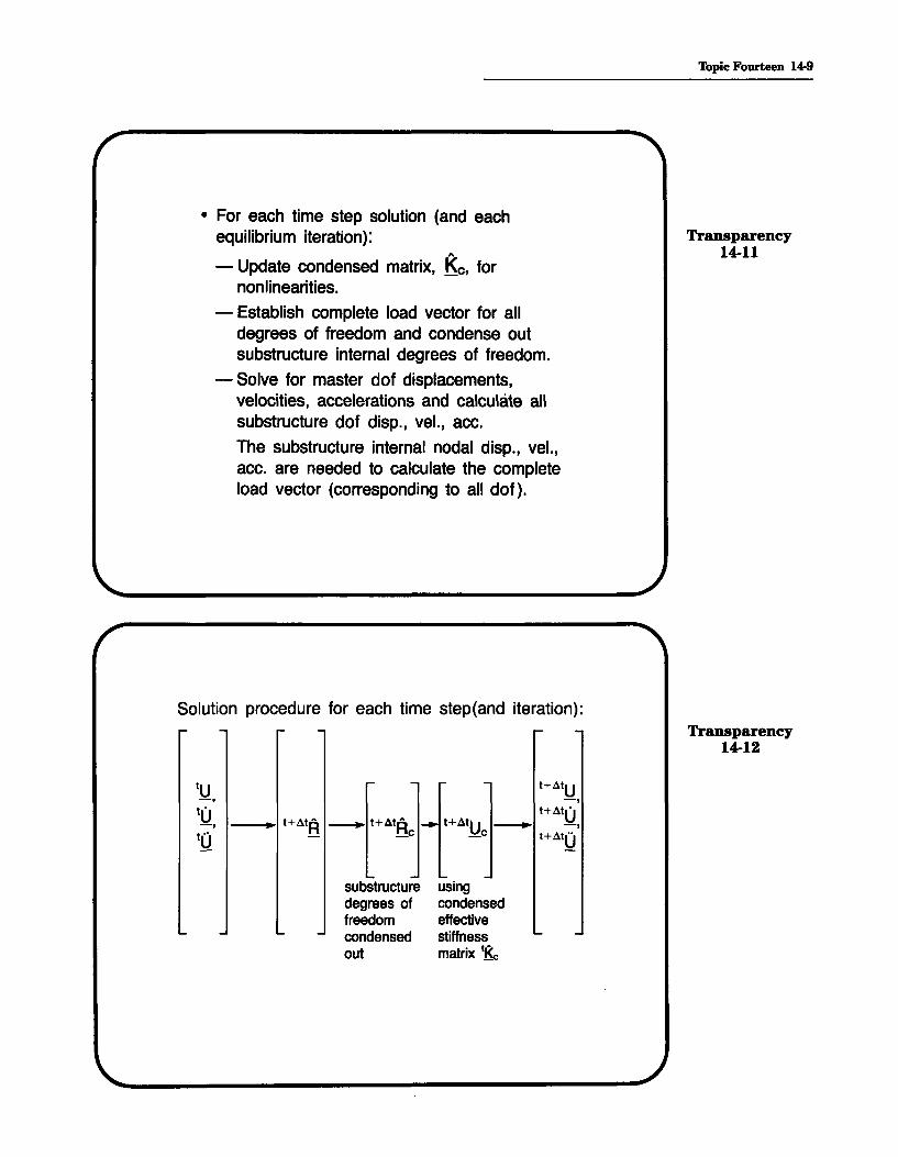
• For each time step solution (and eachequilibrium iteration):
- Update condensed matrix, Ke, fornonlinearities.
- Establish complete load vector for alldegrees of freedom and condense outsubstructure internal degrees of freedom.
- Solve for master dof displacements,velocities, accelerations and calculate allsubstructure dof disp., veL, ace.
The substructure internal nodal disp., veL,ace. are needed to calculate the completeload vector (corresponding to all dof).
Solution procedure for each time step(and iteration):
tu t+4tU-, -,tU' t+4t(j-, • t+4tRA _ t+4tRA _ t+41U _ -,.. _ _c _c t+4tU"tu
Topic Fourteen 14-9
Transparency14-11
Transparency14-12
substructuredegrees offreedomcondensedout
usingcondensedeffectivestiffnessmatrix tKe

14-10 Nonlinear Dynamic Response - Part II
Example: Wave propagation in a rodTransparency
14-13
R
Uniform, freely floating rod
/
R
1000 N+------
L = 1.0 mA = 0.01 m'Z.p = 1000 kg/m3
E = 2.0 x 10⁹ Pa
time
Transparency14-14
Consider the compressive force at apoint at the center of the rod:
-.B-1' .5 'I' .5 'I
t* = time for stress waveto travel throughthe rod1000 N
Compressiveforce
IA
The exact solution for the force atpoint A is shown below.
1....-_--+-__\--_-+-_--+__ time1/2 t* t* % t* 2 t*

We now use a finite element mesh often 2-node truss elements to obtainthe compressive force at point A.
All elements uniformly spaced
Topic Fourteen 14-11
Transparency14-15
R • •
Central difference method:
• The critical time step for this problem is
Llt = L Ic = t* ( 1 )cr e number of elements
Llt > Lltcr will produce an unstablesolution
• We need to use the inital conditionsas follows:
aMOO~=OR
~0·· _ °HUj -
mjj
Transparency14-16

14-12 Nonlinear Dynamic Response - Part II
exact
/
1500
• Using a time step equal to atcr• we obtainthe correct result: • For this special
case the exactsolution is obtained
Finite elements
~100QCompressiveforce (N) 500
Transparency14-17
t*
-500
Transparency14-18
• Using a time step equal to ! atcr , thesolution is stable, but highlyinaccurate.
Finite elements1500
1000Compressiveforce (N) 500..
-500.
time

1500
1000Compressiveforce (N) 500
Now consider the use of thetrapezoidal rule:
• A stable solution is obtained withany choice of at.
• Either a consistent or lumpedmass matrix may be used. Weemploy a lumped mass matrix inthis analysis.
Trapezoidal rule, dt = dterlcDM' .i.nitialconditions computed using MOU = OR.
- The solution is inaccurate.Finite element solution,
/"10 element meshAA/
AA exact solution
A A/A
Topic Fourteen 14-13
Transparency14-19
Transparency14-20
-500
t* 2t* timeAA
14-14 Nonlinear Dynamic Response - Part 11
1500
1000Compressiveforce (N)
500
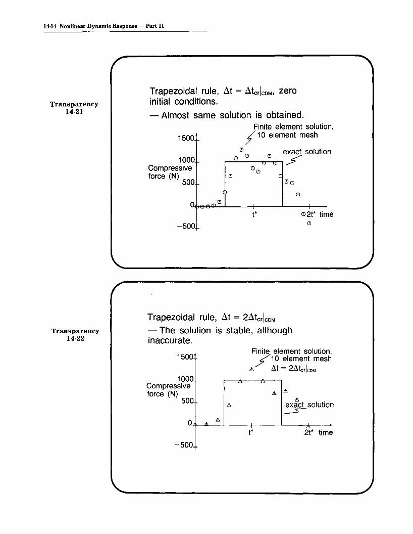
Transparency14-21
Trapezoidal rule, dt = dtcrlcDM' zeroinitial conditions.
- Almost same solution is obtained.Finite element solution,
/ 10 element mesh
(!) (!) (!) exact solution(!) '" ~ f
(!)(!)(!
(!)(!)
Transparency14-22
t*
-500
Trapezoidal rule, dt = 2dtcrlcDM- The solution is stable, althoughinaccurate.
(!)2t* time(!)
1500Finite element solution,/10 element mesh
.t> at = 2atcrlcDM1000
Compressiveforce (N)
500
o ....t>
-500
t*
.t>exact solution~
I!:>
2t* time

Topic Fourteen 14-15
Trapezoidal rule, at = ! atcrlCDMTransparency
14-23
~
~
~<b.
t* ~~ 2t* time~
Finite element solution,er10 element mesh
~ / exact solution~~ Ao.~~ ~~ ~ ~ ~ ~~
~ ~ ~
<~
Ol~",¢ll-~L~-L_--+-__--I._~....... _
1500
1000Compressiveforce (N) 500
-500
The same phenomena are observed whena mesh of one hundred 2-node trusselements is employed.- Here ~tcr = t*/100 exact solution; finite
Finite element element solution,solution, .::It = ! .::lte., .::It = .::ltc., central
1500 central diffefrJrwenMCMeWtMfWrM-.d~iff/erence methodmethod
1000
Compressiveforce (N) 500
Transparency14·24
O+-----J.:L---+---..JH-lMIlIAAi'\r---t*
-50

14-16 Nonlinear Dynamic Response - Part II
Transparency14-25
Transparency14-26
Trapezoidal rule, at = atcrlCDM
Finite element solution, 100 element mesh
1500 /
O,+-----"'-L-----t------'"t-++t-tt1Ht----time
-50
Now consider a two-dimensional modelof the rod: tz
1 0 element 5 L- y. m./>/ .
For this mesh, atcr =P t*/(10 elements)because the element width is less thanthe element length.

If At = t*/(10 elements) is used, the solutiondiverges
-In element 5,
IT 1>- (1000 N)zz 0.01 m2
at t = 1.9 t*
Example: Dynamic response of threedegree-of-freedom systemusing central difference method
Topic Fourteen 14-17
Transparency14-27
Transparency14-28
kL = 1 Ibf/ftm = 1 slug
°X1 = °X2 = °X3 = 0
°*1 = 0.555 ft/sec°*2 = 1.000 ft/sec°*3 = 1.247 ft/sec
FomeL{:0.95
Displacement Ix2 - x3 1
(~tcrit)linear = 1.11 sec(~terit)nonlinear = 0.14 sec

14-18 Nonlinear Dynamic Response - Part II
Transparency14-29
Results: Response of right mass
3
D' 2ISp.
(ft) 1
X1 0 HJ--:-':.-----i~:---___='::n--:--~-
t(sec)-1
-2
-3.: .:1t = 0.05 sec0: .:1t = 0.15 sec
Response of center mass:Transparency
14-30
.:1 =0.05 sec.
.:1 = 0.15 sec..:O'
2Disp.(ft) 1
X2 0 1--If....L-- ~-----J~--....I...--
t(sec)-1
-2

Response of left mass:
Disp.(ft)
X320'
~\,\:>,
.... 0--
t(sec)
Topic Fourteen 14-19
Transparency14-31
.: d=0.05 sec.0: d=0.15 sec.
Force (Ibf) in center truss:
TIME dt=0.05 dt=0.159.0 -0.666 -0.700
12.0 -0.804 -0.87715.0 0.504 0.50318.0 0.648 -0.10021.0 -0.132 -0.05924.0 -0.922 0.550
Transparency14-32

14-20 Nonlinear Dynamic Response - Part II
Transparency14-33
Example: 10 story tapered tower
3.2 m--1~
Pressureinducedbyblast
Applied load (blast):
32 m
Girder properties:E=2.07x 10¹¹ Pav=0.3A=0.01 m2
As =0.009 m2
1=8.33x 10⁻⁵ m4
p = 7800 kg/m3
Transparency14-34 2000
Forceperunitlength(N/m)
1000
o+---+-----+---+--~---o 50 100 150 200
time (milliseconds)

Purpose of analysis:
• Determine displacements,velocities at top of tower.
• Determine moments at base oftower.
We use the trapezoidal rule and alumped mass matrix in the followinganalysis.
We must make two decisions:
• Choose mesh (specifically thenumber of elements employed).
• Choose time step ~t.
These two choices are closely related:
The mesh and time step to be useddepend on the loading applied.
Topic Fourteen 14·21
Transparency14-35
Transparency14-36

14-22 Nonlinear Dynamic Response - Part II
Transparency14-37
Transparency14-38
Some observations:
• The choice of mesh determinesthe highest natural frequency (andcorresponding mode shape) that isaccurately represented in the finiteelement analysis.
• The choice of time step determines the highest frequency ofthe finite element mesh in whichthe response is accurately integrated during the time integration.
• Hence, it is most effective tochoose the mesh and time stepsuch that the highest frequencyaccurately "integrated" is equal tothe highest frequency accuratelyrepresented by the mesh.
• The applied loading can be represented as a Fourier series whichdisplays the important frequenciesto be accurately represented bythe mesh.

Force perunit length(N/m)
Consider the Fourier representation ofthe load function:
f(t) = ~o +I (ancos(2'ITfnt) +bnsin(2'ITfnt»n=1
Including terms up to
case 1: fn= 17 Hz
case 2: fn= 30 Hz
The loading function is represented asshown next.
Fourier approximation including termsup to 17 Hz:
/APPlied load
/FOUrier approximation
o 100 200time (milliseconds)
Thpic Fourteen 14-23
Transparency14-39
Transparency14-40

14-24 Nonlinear Dynamic Response - Part II
Transparency14-41
Transparency14-42
Fourier approximation including termsup to 30 Hz:
2000Force perunit length(N/m)
1000
100 200time (milliseconds)
• We choose a 30 element mesh,a 60 element mesh and a 120element mesh. All elements are2-node Hermitian beam elements.
30 elements 60 elements 120 elements

Thpic Fourteen 14-25
Determine "accurate" natural frequen- .cies represented by 30 element mesh:
From eigenvalue solutions of the 30and 60 element meshes, we find
Transparency14-43
rate
curate
mode natural frequencies (Hz)number 30 element mesh 60 element mesh
1 1.914 1.9142 4.815 4.828 accu3 8.416 8.480
14 12.38 12.585 16.79 17.276 21.45 22.47
17 26.18 28.088 30.56 29.80
inac
Calculate time step:
Tco = 117 Hz = .059 sec
~t= 21 Tco = .003 sec
• A smaller time step would accurately"integrate" frequencies, which are notaccurately represented by the mesh.
• A larger time time step would notaccurately "integrate" all frequencieswhich are accurately represented bythe mesh.
Transparency14-44

14-26 Nonlinear Dynamic Response - Part II
Transparency14-45
Determine "accurate" natural frequencies represented by 60 element mesh:
From eigenvalue solutions of the 60and 120 element meshes, we find
rate
ate
mode natural frequencies (Hz)number 60 element mesh 120 element mesh
5 17.27 17.286 22.47 22.49 accur
7 28.08 28.148 29.80 29.759 32.73 33.85
10 33.73 35.0611 36.30 38.96 inaccu
Calculate time step:Transparency
14-46 Teo = 31 Hz= .033 sec
Llt == 2~ Teo = .0017 sec
• The meshes chosen correspond tothe Fourier approximations discussedearlier:
30 element mesh _.---" Fourier approximationincluding terms upto 17 Hz.
60 element mesh _.-_a Fourier approximationincluding terms upto 30 Hz.

Pictorially, at time 200 milliseconds,we have (note that the displacementsare amplified for visibility):
Topic Fourteen 14-27
Transparency14-47
30 elements 60 elements
Pictorially, at time 400 milliseconds,we have (note that the displacementsare amplified for visibility):
Transparency14-48
30 elements 60 elements

14-28 Nonlinear Dynamic Response - Part II
Transparency14-49
Consider the moment reaction at thebase of the tower:
40
20
M(KN-m)
500250
time (milliseconds)
Ol-+----------if---+-------+--
- : 30 elements/VVV: 60 elements
-20
-40
Transparency14-50
Consider the horizontal displacementat the top of the tower:
~6IJ .lementsr u
.06 11.04u
30 .i.1s(m).02
0250 500
-.02 time (milliseconds)
-.04
-.06

Consider the horizontal velocity at thetop of the tower:
'Ibpic Fourteen 14·29
Transparency14-51
.6
V(m/s)
-.2
-.4
-.6
Comments:
IV
11
• The high-frequency oscillationobserved in the moment reactionfrom the 60 element mesh isprobably inaccurate. We note thatthe frequency of the oscillation isabout 110Hz (this can be seendirectly from the graph).
• The obtained solutions for thehorizontal displacement at the topof the tower are virtually identical.
Transparency14-52

14-30 Nonlinear Dynamic Response - Part II
Transparency14-53
Example: Simple pendulum undergoinglarge displacements
~ length = 304.43 cm
tip/"mass = 10 kg
g = 980 cm/sec2
1Initial conditions:
°0 = 900
°0 = 0
One truss element with tip concentratedmass is employed.
Transparency14-54
Calculation of dynamic response:
• The trapezoidal rule is used tointegrate the time response.
• Full Newton iterations are used toreestablish equilibrium during everytime step.
• Convergence tolerance:ETOL= 10- 7
(a tight tolerance)

Topic Fourteen 14-31
Choose Llt = 0.1 sec. The followingresponse is obtained: Transparency
14-55
6 time (sec)
last obtained solutionSolution procedurefailed during next
'i~ep90
-90
-45
e 45
(degrees)o+---!'r--+---P--+----.:::I---+---
The strain in the truss is plotted:
• An instability is observed.Transparency
14-56
time(sec)
2
5x10~5
strain
-10x10- 5

14-32 Nonlinear Dynamic Response - Part II
Transparency14-57
Transparency14-58
• The instability is unchanged whenwe tighten our convergence tolerances.
• The instability is also observedwhen the BFGS algorithm isemployed.
• Recall that the trapezoidal rule isunconditionally stable only in linearanalysis.
Choose at = 0.025 sec, using theoriginal tolerance and the full Newtonalgorithm (without line searches).
• The analysis runs to completion.
pFinite element solution
6 4(degrees)
0time
-45 (sec)
-9

Topic Fourteen 14-33
The strain in the truss is stable: Transparency14-59
strain
3x10- 6
2x 10⁻⁶
finite element solution,At=.025 sec
1
4o+----!IL..-----+l~---lL-_fL_-><--___t_>''----
8 12 time (sec)
1 X 10⁻⁶
It is important that equilibrium be accuratelysatisfied at the end of each time step: Transparency
14·60Finite element solution, at = .025 sec.,equilibrium iterations used asdescribed above.
f90
-45
-90
6 45(degrees) time (sec)
O-l---lf--~"'I=-b-==+-~+=-+=I=:---12"\Finite element solution,at = .025 sec., noequilibrium iterationsused.

14-34 Nonlinear Dynamic Response - Part II
5x10- 5
Transparency14-61
Although the solution obtained withoutequilibrium iterations is highlyinaccurate, the solution is stable:
Finite element solution, At=O.025 sec.,
10 x 10- 5 no equilibrium iterations used.
strain f Finite element solution, 8t=O.025 sec.,equilibrium iterations used asdescribed above.
4 8 12 time (sec)
Transparency14-62
Example: Pipe whip analysis:
360 P=6.57x 10⁵ Ib
~ 2775
=~OxJ30~~-z-diameter
not drawn restraint 5.75to scale
all dimensions in inches
• Determine the transient responsewhen a step load P is suddenlyapplied.

Finite element model:
Six Hermitian beam elements
~>---".--••-----<._--4.l---".-~ ~~~ent
• The truss element incorporates a3 inch gap.
Material properties:Pipe: E = 2.698 x 10⁷ psi
v=0.3CTy=2.914x 10⁴ psi
~~8~2 x 10- 3 S.IU39 = 7.18 x 10- 4 Ibf~S~C2
In In
Restraint: E = 2.99 x 10⁷ psiCTy= 3 .80 x 104 psiET=O
Topic Fourteen 14-35
Transparency14-63
Transparency14-64

14-36 Nonlinear Dynamic Response - Part II
Transparency14-65
Transparency14-66
The analysis is performed using
Mode superposition (2 modes)
Direct time integration
We use, for each analysis,
Trapezoidal rule
- Consistent mass matrix
A convergence tolerance ofETOL = 10-7 is employed.
Eigenvalue solution:
Mode 1, natural frequency = 8.5 Hz
Mode 2, natural frequency = 53 Hz

Choice of time step:
We want to accurately integrate thefirst two modes:
at == 2~ Tco = 2~ ((freqUency ~f mode 2))
=.001 sec
Note: This estimate is based solely on a linearanalysis (Le, before the pipe hits therestraint and while the pipe is still elastic).
Determine the tip displacement:
'Ibpic Fourteen 14-37
Transparency14-67
time Transparency(milliseconds) 14-68
0 2 4 6 8 100
~~
tip -2(!)~
disp. (!) Gap(in) (!)
-4 ~(!)~
~~ (!)
C!l - mode superposition ~
-6 ~ - direct integration

14-38 Nonlinear Dynamic Response - Part II
Transparency14-69
Determine the moment at the built-inend of the beam:
time(milliseconds)
0 2 4 6 8 10Moment 0(Ib-in) (!) ~
(!)
-1 X 10⁷(!) ~
~
-2X 10⁷(!) ~ (!)
~
-3x 10⁷ (!) (!)(!) (!)
~~
-4 X 10⁷
(!) - mode superposition~ - direct integration

r~ii•• 12, 5,n2.1 I
r-- ....~EI, constant
Topic Fourteen 14-39
Slide14-1
l
l
l
L • 38 9 In
d • 0.1 in
-x
lit'~H~
WAnalysis of CAD housing with lower support
TIME ISECONlSTIP
DEFLECTION(INCHES) 0,.--_~~__~=--_~O.o¥-,3!..-_~:!..-_~~_~~_~0.07
-0.02
-0.04
- PETERSON AND BATHE-0.06
o DIRECT INTEGRATION
-0.08 '" MODE 5UPERPOS ITION12 MODES)
-0.10
CRD housing tip deflection
Slide14-2

14-40 Nonlinear Dynamic Response - Part II
Slide14-3
p
wR = 22.27 in.h = 0.41 in.e= 26.67"
E = 1.05 X 10⁷ Ib/in2
v = 0.3cry = 2.4 X 10⁴ Ib/in2
ET = 2.1 X 10⁵ Ib/in2
p = 9.8 X 10⁻² Ib/in3
Slide14-4
Ten a-node axisymmetric els.Newmark inte (8 = 0.55, (X = 0.276)2 x 2 Gauss integration ~L-consistent mass 600Ib/in~
~t = 10f-Lsec, T.L. 0 TIME
Spherical cap nodes under uniform pressure loading
TIME - msec
o 0·2 0·4 0.6 0.8 1.0~---r--.-------,---,------,
DEFLECTIONW.-Inches
0·02
0.04
0·06
0.08
Dynamic elastic-plastic response of a spherical cap.p deformation independent

TIME - msec
o 0·2 0·4 0·6 0·8 1-0~--.-------,--.-----.------,
Topic Fourteen 14-41
Slide14-5
DEFLECTIONWo- inches
0·02
0·04
0·06
Newmark integration(1= D.5, llC- 0.25)
0·08
Response of the cap using consistent and lumpedmass idealization
TIME - msec
°..,....-_0.:,..::.2__0::.,..4_--=0.,...6::....---=.0...:8:...--.:.,1.0
DEFLECTION
We-IncheS
0·02
0·04
0·06
0·08
Nagarajan& Popov "
Consistent massNewmark integration
r:5"=O~)
~'.'\.....
Slide14-6
Effect of numbers of Gauss integration points on thecap response predicted

14·42 Nonlinear Dynamic Response - Part II
Slide14-7
BLIND FLANGEJ ~ULSE GUN 3-Inch FLEXIBLE NI 200 PIPE~ \
m P: r~~p,B ~
1._-----3---'nc-"~:I-GI~D-P-IP-E ~_"*,,.,J JNICKEL 200
E= 30'10' PSIET= 73.7 110 4 PSI• • 030P = B.3I.10- 4 SLUG;FTITo = 12.B'103 PSI IN
WATERK = 32 liO' PSIP = 9.36 • 10-\~FT
Slide14·8
Analysis of fluid-structure interaction problem(pipe test)
2500
2000
1500PRESSURE
IPSI) 000I
500
1.0 20TIME (MSEC)
3.0 4.0
PRESSURE PULSE INPUT

MESH MODEL FOR NI PIPE
t[[ttr'----.If..-~.'""~
I RIGID PIPE Iyt,_.----"'-'~_••
Finite element model
Topic Fourteen 14-43
Slide14-9
~ilDI~d
f.lI'lR'l,I(~Tdl
- ~Ol~d
[lP(RIIII(IO'Al-ilD,,.A
OP(HllIlIIIAl
Slide14-10
I.~ 1.0 2.5llllflllSE(1
Pili II I I! IN f HOM NICOl l PIP~ IP 31
1.0 ,.5 l.~ lP :.~ 4.0 0l-,....,.-4,....,r-tt-~..,."....,._"II[IIIIS[(1
PI T: AT . _~ ,.. '1010 IOI(_E l PIP!
'-dOIU[lPfRIM(Nlo\l
o w w w w ~ w w WIIf1l(llIIS(CI
PillAr ~IN INIONICKHPlP( !pel
-ADINA[IPfHIIII[NTdl
o I.C U J.C 4.C b,() '.0 atHlf :t,l5[:
<; IHAI NAT <.5 'N ,ro fe N'('E ~ PI PI:

MIT OpenCourseWare http://ocw.mit.edu
Resource: Finite Element Procedures for Solids and Structures Klaus-Jürgen Bathe
The following may not correspond to a particular course on MIT OpenCourseWare, but has been provided by the author as an individual learning resource.
For information about citing these materials or our Terms of Use, visit: http://ocw.mit.edu/terms.