solution manual for digital systems: principles and ... · solution manual for digital systems:...
TRANSCRIPT

Solution Manual for Digital Systems: Principles and
Applications 11th edition by Neal Widmer and Greg Moss
Chapter 1. Introductory Concepts
Unit 1 Introduction to the DE0, DE1, or DE2 Development &
Education Board Project: Intro2DE0, Intro2DE1, or Intro2DE2
1.3 Logic Switches
Board DE0 DE1 DE2
# switches 10 10 18
Logic Switch LEDG1 Logic level Voltage at
SW1 (on/off) (high/low) connector pin
Down Off Low ~0 V
Up On High ~3.3 V
1
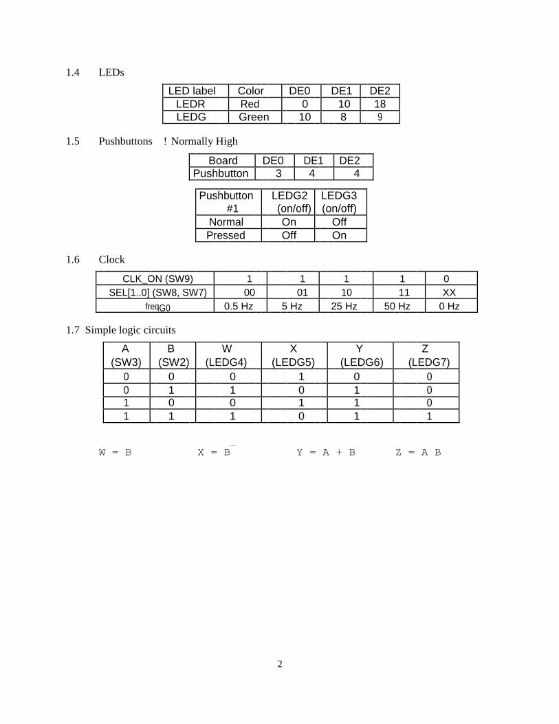
1.4 LEDs
LED label Color DE0 DE1 DE2
LEDR Red 0 10 18
LEDG Green 10 8 9
1.5 Pushbuttons Normally High
Board DE0 DE1 DE2
Pushbutton 3 4 4
Pushbutton LEDG2 LEDG3
#1 (on/off) (on/off)
Normal On Off
Pressed Off On
1.6 Clock
CLK_ON (SW9) 1 1 1 1 0
SEL[1..0] (SW8, SW7) 00 01 10 11 XX
freqG0 0.5 Hz 5 Hz 25 Hz 50 Hz 0 Hz
1.7 Simple logic circuits
A B W X Y Z
(SW3) (SW2) (LEDG4) (LEDG5) (LEDG6) (LEDG7)
0 0 0 1 0 0
0 1 1 0 1 0
1 0 0 1 1 0
1 1 1 0 1 1
_
W = B X = B Y = A + B Z = A B
2

Unit 2 Testing Combinational Logic Circuits Using DE0, DE1, or DE2 Boards
Project: Lab2DE0, Lab2DE1, or Lab2DE2
3
4

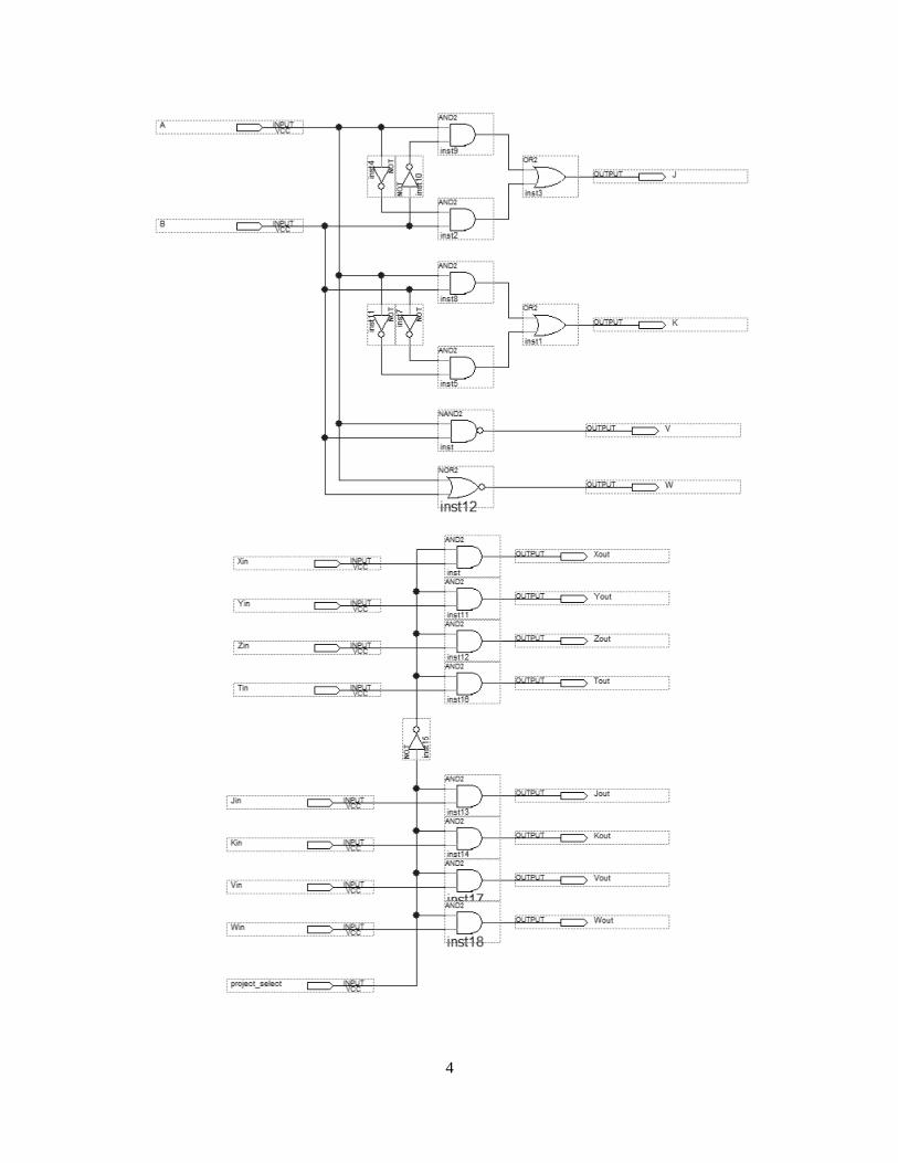
2.1 Simple circuits _
X = A + A B = A Y = A + A B = A + B
_ _ _ Z = A (A + B) = A B T = A B + A B + A B = A + B
A B T Z Y X J K W V
0 0 0 0 0 0 0 1 1 1
0 1 1 0 1 0 1 0 0 1
1 0 1 0 1 1 1 0 0 1
1 1 1 1 1 1 0 1 0 0
2.2 More circuit functions ___
V = A B
_____
W = A + B _
_ _ _ _____
J = A B + A B = A
∀
B
K = A B + A B = A
∀
B
5

Unit 3 Schematic Capture & Analysis of Combinational Logic Circuits
3.1 Example 3-1 (see Lab Manual Example 3-1 & Quartus Tutorial 1 – Schematic)
3.2 Equivalent circuits
(a) V = W? true
V = A (B + C)
W = A C + A B
(b) X = Y? true _ _
X = A B + A B + A C
_ _ _
Y = A B + A B + B C
A B C V W X Y
0 0 0 0 0 1 1
0 0 1 0 0 1 1
0 1 0 0 0 0 0
0 1 1 0 0 0 0
1 0 0 0 0 0 0
1 0 1 1 1 1 1
1 1 0 1 1 1 1
1 1 1 1 1 1 1
3.3DeMorgan’s theorem
(a) p1 = p2 = p3? true
_ _ _ _ _____
p1 = a b p2 = a b p3 = a + b
(b) q1 = q2 = q3? true
_ _ _ _ ___
q1 = a + b q2 = a + b q3 = a b
a b p q
0 0 1 1
0 1 0 1
1 0 0 1
1 1 0 0
6

3.4 2-bit adder
7