solution guide iia - mvtecdownload.mvtec.com/...12.0-solution-guide-ii-a-image-acquisition.pdf ·...
TRANSCRIPT

the power of machine vision
Solution Guide II-AImage Acquisition

The Art of Image Acquisition, Version 12.0.2
All rights reserved. No part of this publication may be reproduced, stored in a retrieval system, or transmitted in any form or byany means, electronic, mechanical, photocopying, recording, or otherwise, without prior written permission of the publisher.
Edition 1 June 2002 (HALCON 6.1)Edition 2 December 2003 (HALCON 7.0)Edition 3 June 2007 (HALCON 8.0)Edition 4 December 2008 (HALCON 9.0)Edition 4a June 2009 (HALCON 9.0.1)Edition 4b October 2010 (HALCON 10.0)Edition 5 November 2011 (HALCON 10.0.2)Edition 6 May 2012 (HALCON 11.0)Edition 7 November 2014 (HALCON 12.0)Edition 7a July 2015 (HALCON 12.0.1)
Copyright © 2002-2016 by MVTec Software GmbH, München, Germany MVTec Software GmbH
Protected by the following patents: US 7,062,093, US 7,239,929, US 7,751,625, US 7,953,290, US 7,953,291, US8,260,059, US 8,379,014, US 8,830,229. Further patents pending.
Microsoft, Windows, Windows Vista, Windows Server 2008, Windows 7, Windows 8, Windows 10, Microsoft .NET,Visual C++, Visual Basic, and ActiveX are either trademarks or registered trademarks of Microsoft Corporation.Linux is a trademark of Linus Torvalds.
All other nationally and internationally recognized trademarks and tradenames are hereby recognized.
More information about HALCON can be found at: http://www.halcon.com/

About This Manual
Obviously, the acquisition of images is a task to be solved in all machine vision applications. Unfortu-nately, this task mainly consists of interacting with special, non-standardized hardware in form of imageacquisition devices, i.e., cameras or frame grabber boards. To let you concentrate on the actual machinevision problem, HALCON already provides interfaces performing this interaction for a large number ofimage acquisition devices (see section 1 on page 7).
Within your HALCON application, the task of image acquisition is thus reduced to a few lines of code,i.e., a few operator calls, as can be seen in section 2 on page 9. What’s more, this simplicity is notachieved at the cost of limiting the available functionality: Using HALCON, you can acquire imagesfrom various configurations of frame grabbers and cameras (see section 3 on page 11) in different timingmodes (see section 5 on page 25).
The example programs that are presented in this Solution Guide can be found in the specified subdirec-tories of the directory %HALCONEXAMPLES%. Note that most programs are preconfigured to work with acertain HALCON acquisition interface; in this case, the name of the program contains the name of the in-terface. To use the program with another image acquisition device, please adapt the parts which open theconnection to the device. More example programs for the different HALCON acquisition interfaces canbe found in the subdirectory hdevelop\Image\Acquisition of the directory %HALCONEXAMPLES%.
Please refer to the Programmer’s Guide, chapter 13 on page 115 and chapter 23 on page 195, for informa-tion about how to compile and link the C++ and C example programs; among other things, they describehow to use the example makefiles for Unix-like systems which can be found in the subdirectories c
and cpp of the directory %HALCONEXAMPLES%. Under Windows, you can use Visual Studio workspacescontaining the examples, which can be found in the subdirectory win parallel to the source files.


Contents
1 The Philosophy Behind the HALCON Acquisition Interfaces 7
2 A First Example 9
3 Connecting to Your Image Acquisition Device 113.1 Opening a Connection to a Specified Configuration . . . . . . . . . . . . . . . . . . . . 123.2 Connecting to Multiple Boards and Cameras . . . . . . . . . . . . . . . . . . . . . . . . 12
3.2.1 Single Camera . . . . . . . . . . . . . . . . . . . . . . . . . . . . . . . . . . . 123.2.2 Multiple Boards . . . . . . . . . . . . . . . . . . . . . . . . . . . . . . . . . . 123.2.3 Multiple Handles Per Board . . . . . . . . . . . . . . . . . . . . . . . . . . . . 143.2.4 Port Switching . . . . . . . . . . . . . . . . . . . . . . . . . . . . . . . . . . . 143.2.5 Simultaneous Grabbing (Only For Specific Interfaces) . . . . . . . . . . . . . . 15
3.3 Requesting Information About the Image Acquisition Interface . . . . . . . . . . . . . . 15
4 Configuring the Acquisition 194.1 General Parameters . . . . . . . . . . . . . . . . . . . . . . . . . . . . . . . . . . . . . 194.2 Special Parameters . . . . . . . . . . . . . . . . . . . . . . . . . . . . . . . . . . . . . 204.3 Fixed vs. Dynamic Parameters . . . . . . . . . . . . . . . . . . . . . . . . . . . . . . . 22
5 The Various Modes of Grabbing Images 255.1 Real-Time Image Acquisition . . . . . . . . . . . . . . . . . . . . . . . . . . . . . . . . 25
5.1.1 Non-Real-Time Grabbing Using grab_image . . . . . . . . . . . . . . . . . . . 255.1.2 Grabbing Without Delay Using Asynchronously Resettable Cameras . . . . . . 275.1.3 Volatile Grabbing . . . . . . . . . . . . . . . . . . . . . . . . . . . . . . . . . . 275.1.4 Real-Time Grabbing Using grab_image_async . . . . . . . . . . . . . . . . . . 295.1.5 Continuous Grabbing . . . . . . . . . . . . . . . . . . . . . . . . . . . . . . . . 315.1.6 Using grab_image_async Together With Asynchronously Resettable Cameras . . 335.1.7 Specifying a Maximum Delay . . . . . . . . . . . . . . . . . . . . . . . . . . . 33
5.2 Using an External Trigger . . . . . . . . . . . . . . . . . . . . . . . . . . . . . . . . . . 355.2.1 Special Parameters for External Triggers . . . . . . . . . . . . . . . . . . . . . 37
5.3 Acquiring Images From Multiple Cameras . . . . . . . . . . . . . . . . . . . . . . . . . 375.3.1 Dynamic Port Switching and Asynchronous Grabbing . . . . . . . . . . . . . . 375.3.2 Simultaneous Grabbing . . . . . . . . . . . . . . . . . . . . . . . . . . . . . . . 38
6 Miscellaneous 396.1 Acquiring Images From Standardized Image Acquisition Devices . . . . . . . . . . . . . 39

6.2 Acquiring Images From Unsupported Image Acquisition Devices . . . . . . . . . . . . . 406.3 Grabbing Image Arrays and Preprocessed Image Data . . . . . . . . . . . . . . . . . . . 426.4 Error Handling . . . . . . . . . . . . . . . . . . . . . . . . . . . . . . . . . . . . . . . 42
6.4.1 Error Handling in HDevelop . . . . . . . . . . . . . . . . . . . . . . . . . . . . 436.4.2 Error Handling Using HALCON/C . . . . . . . . . . . . . . . . . . . . . . . . 446.4.3 Error Handling Using HALCON/C++ . . . . . . . . . . . . . . . . . . . . . . . 456.4.4 Error Handling Using HALCON/COM . . . . . . . . . . . . . . . . . . . . . . 456.4.5 Error Handling Using HALCON/.NET . . . . . . . . . . . . . . . . . . . . . . 46
6.5 Callback Functions . . . . . . . . . . . . . . . . . . . . . . . . . . . . . . . . . . . . . 466.6 Line Scan Cameras . . . . . . . . . . . . . . . . . . . . . . . . . . . . . . . . . . . . . 46
A HALCON Images 51A.1 The Philosophy of HALCON Images . . . . . . . . . . . . . . . . . . . . . . . . . . . . 51A.2 Image Tuples (Arrays) . . . . . . . . . . . . . . . . . . . . . . . . . . . . . . . . . . . 52A.3 HALCON Operators for Handling Images . . . . . . . . . . . . . . . . . . . . . . . . . 52
A.3.1 Creation . . . . . . . . . . . . . . . . . . . . . . . . . . . . . . . . . . . . . . . 52A.3.2 Channels . . . . . . . . . . . . . . . . . . . . . . . . . . . . . . . . . . . . . . 53A.3.3 Domain . . . . . . . . . . . . . . . . . . . . . . . . . . . . . . . . . . . . . . . 53A.3.4 Access . . . . . . . . . . . . . . . . . . . . . . . . . . . . . . . . . . . . . . . 53A.3.5 Manipulation . . . . . . . . . . . . . . . . . . . . . . . . . . . . . . . . . . . . 53A.3.6 Image Tuples . . . . . . . . . . . . . . . . . . . . . . . . . . . . . . . . . . . . 53
B Parameters Describing the Image 55B.1 Image Size . . . . . . . . . . . . . . . . . . . . . . . . . . . . . . . . . . . . . . . . . 55B.2 Image Data . . . . . . . . . . . . . . . . . . . . . . . . . . . . . . . . . . . . . . . . . 56
C Object Appearance 59C.1 Lighting . . . . . . . . . . . . . . . . . . . . . . . . . . . . . . . . . . . . . . . . . . . 59
C.1.1 Reflection Properties of the Object . . . . . . . . . . . . . . . . . . . . . . . . . 60C.1.2 Characteristics of the Light Source . . . . . . . . . . . . . . . . . . . . . . . . . 60
C.2 Geometry . . . . . . . . . . . . . . . . . . . . . . . . . . . . . . . . . . . . . . . . . . 63

The Philosophy Behind the HALCON Acquisition Interfaces A-7
Chapter 1
The Philosophy Behind theHALCON Acquisition Interfaces
From the point of view of a user developing software for a machine vision application, the acquisitionof images is only a prelude to the actual machine vision task. Of course it is important that images areacquired at the correct moment or rate, and that the camera and the frame grabber are configured suitably,but these tasks seem to be elementary, or at least independent of the used image acquisition device.
The reality, however, looks different. Image acquisition devices differ widely regarding the providedfunctionality, and even if their functionality is similar, the SDKs (software development kit) provided bythe manufacturers do not follow any standard so far. Therefore, switching to a different image acquisitiondevice probably requires to rewrite the image acquisition part of the application.
HALCON’s answer to this problem are its image acquisition interfaces (IAI) which are provided to cur-rently more than 50 frame grabbers and hundreds of industrial cameras (analog, Camera Link, USB 2.0,IEEE 1394, and GigE) in form of dynamically loadable libraries (Windows: DLLs; OS X: shared li-braries). HALCON image acquisition interfaces bridge the gap between the individual image acquisitiondevices and the HALCON library, which is independent of the used image acquisition device, computerplatform, and programming language (see figure 1.1). In other words, they
• provide a standardized interface to the HALCON user in form of 15 HALCON operators, and
• encapsulate details specific to the frame grabber or camera, i.e., the interaction with the SDKprovided by the device manufacturer.
Therefore, if you decide to switch to a different image acquisition device, all you need to do is to installthe corresponding driver and SDK provided by the manufacturer and to use different parameter valueswhen calling the HALCON operators; the operators themselves stay the same.
In fact, the elementary tasks of image acquisition are covered by two HALCON operators:
• open_framegrabber connects to the image acquisition device and sets general parameters, e.g.,the type of the used camera or the port the camera is connected to, then
Phi
loso
phy

A-8 The Philosophy Behind the HALCON Acquisition Interfaces
computer
camera
softwareframe
grabber
hAcqxyz.dll
HALCON xyz acquisition interface
device driver & SDK
HALCON image processing libraryhalcon.dll & halconc/cpp/dotnet/x.dll
HALCON applicationHDevelop / C / C++ / C# / Visual Basic
Figure 1.1: From the camera to a HALCON application.
• grab_image (or grab_image_async, see section 5.1 on page 25 for the difference) grabs images.If not only a single image but an array of images or preprocessed image data like regions or con-tours have to be grabbed, grab_data or grab_data_async can be used (see also section 6.3 onpage 42).
If an image acquisition device provides additional functionality, e.g., on-board modification ofthe image signal, special grabbing modes, or digital output lines, it is available via the operatorset_framegrabber_param (see section 4 on page 19).
Note, that for some image acquisition devices the full functionality is not available within HALCON;please refer to the corresponding online documentation which can be found in the directory %HALCON-
ROOT%\doc\html\manuals or via the HALCON folder in the Windows start menu (if you installedthe documentation). The latest information can be found under http://www.halcon.com/image-acquisition.
If the image acquisition device you want to use is not (yet) supported by HALCON, you can neverthelessuse it together with HALCON. Please refer to section 6.2 on page 40 for more details.
Please note that with HALCON 8.0 our terminology has changed: Since digital cameras, which areconnected by USB 2.0, IEEE 1394 or GigE, are not really based on an actual frame grabber board, weno longer use the term HALCON frame grabber interface. Instead, we use the term HALCON acquisi-tion interface, and the term image acquisition device is used as a substitute for either a frame grabberboard or a digital camera. For backwards compatibility reasons, the names of the HALCON opera-tors have been unchanged, thus, the operator names open_framegrabber, info_framegrabber, andclose_framegrabber may sound a little bit old-fashioned.

A First Example A-9
Chapter 2
A First Example
In this section we start with a simple image acquisition task, which uses the image acquisition devicein its default configuration and the standard grabbing mode. The grabbed images are then segmented.To follow the example actively, start the HDevelop program solution_guide\image_acquisition\
first_example_acquisition.hdev, then press Run once to initialize the application.
Step 1: Connect to the frame grabber
open_framegrabber (AcqName, 1, 1, 0, 0, 0, 0, 'default', -1, 'default', -1, \
'false', CameraType, myBoard, -1, -1, AcqHandle)
When opening the connection to your image acquisition device using the operator open_framegrabber,the main parameter is the Name of the corresponding HALCON acquisition interface. As a result, youobtain a so-called handle (AcqHandle), by which you can access the image acquisition device, e.g., incalls to the operator grab_image.
b)a)
Figure 2.1: a) Acquired image; b) processed image (automatic segmentation).
Firs
tExa
mpl
e

A-10 A First Example
In the example, default values are used for most other parameters (’default’ or -1); section 4.1 onpage 19 takes a closer look at this topic. How to connect to more complex frame grabber and cameraconfigurations is described in section 3 on page 11.
Step 2: Grab an image
grab_image (Image, AcqHandle)
After successfully connecting to your image acquisition device you can grab images by calling the oper-ator grab_image with the corresponding handle AcqHandle. More advanced modes of grabbing imagesare described in section 5 on page 25.
Step 3: Grab and process images in a loop
while (Button != 1)
grab_image (Image, AcqHandle)
auto_threshold (Image, Regions, 4)
connection (Regions, ConnectedRegions)
get_mposition (WindowHandleButton, Row, Column, Button)
endwhile
In the example, the grabbed images are then automatically segmented using the operatorauto_threshold (see figure 2.1). This is done in a loop which can be exited by clicking into a windowwith the left mouse button.
Connecting to Your Image Acquisition Device A-11
Chapter 3
Connecting to Your ImageAcquisition Device
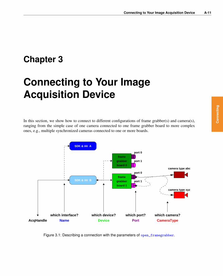
In this section, we show how to connect to different configurations of frame grabber(s) and camera(s),ranging from the simple case of one camera connected to one frame grabber board to more complexones, e.g., multiple synchronized cameras connected to one or more boards.
camera type abc
camera type xyz
port 0
port 1
port 0
port 1
Name Device Port CameraType
which camera?which port?which device?
AcqHandle
which interface?
SDK & IAI A
SDK & IAI B
board 0
frame
grabber
board 1
frame
grabber
Figure 3.1: Describing a connection with the parameters of open_framegrabber.
Con
nect
ing

A-12 Connecting to Your Image Acquisition Device
3.1 Opening a Connection to a Specified Configuration
With the operator open_framegrabber you open a connection to an image acquisition device. Thisconnection is described by four parameters (see figure 3.1): First, you select an acquisition interfacewith the parameter Name. The parameter Device specifies the actual board or camera; depending onthe acquisition interface, this parameter can contain a string describing the board or simply a number (inform of a string!).
Often, the camera can be connected to the frame grabber at different ports, whose number can be selectedvia the parameter Port (in rare cases LineIn). The parameter CameraType describes the connectedcamera: For analog cameras, this parameter usually specifies the used signal norm, e.g., ’ntsc’. Fordigital cameras, this parameter typically specifies the camera model; more complex acquisition interfacesuse this parameter to select a camera configuration file.
As a result, open_framegrabber returns a handle for the opened connection in the parameter AcqHan-dle. Note that if you use HALCON’s COM or C++ interface and call the operator via the correspondingclasses, e.g., HFramegrabber in C++, no handle is returned because the instance of the class itself actsas your handle.
With HDevelop’s Image Acquisition Assistant you can easily connect to your image acquisition deviceand choose suitable parameters (for details see the HDevelop User’s Guide, section 7.1 on page 241),which is very useful to setup your vision system (illumination, focus, field of view).
3.2 Connecting to Multiple Boards and Cameras
Most HALCON acquisition interfaces allow to use multiple frame grabber boards and cameras. However,there is more than one way to connect cameras and boards and to access these configurations from withinHALCON. Below, we describe the different configurations; please check the online documentation ofthe HALCON interface for your image acquisition device (see %HALCONROOT%\doc\html\manuals,the HALCON folder in the Windows start menu, or http://www.halcon.com/image-acquisition)which configurations it supports.
3.2.1 Single Camera
Figure 3.2a shows the simplest configuration: a single camera connected to a single board, accessiblevia a single handle. Some frame grabbers, especially digital ones, only support this configuration; asdescribed in the following section, you can nevertheless use multiple cameras with such frame grabbersby connecting each one to an individual board. Note that this configuration is the typical one in case ofdigital cameras connected by USB 2.0, IEEE 1394, or GigE.
3.2.2 Multiple Boards
Figure 3.2b shows a configuration with multiple cameras, each connected to a separate board. In thiscase you call the operator open_framegrabber once for each connection as in the HDevelop exampleprogram solution_guide\image_acquisition\multiple_boards.hdev.

3.2 Connecting to Multiple Boards and Cameras A-13
frame grabber
board 0
frame grabber
board 1
frame grabber
board 0
frame grabber
board 0
frame grabber
board 0
frame grabber
board 1
frame grabber
board 0
frame grabber
board 1
frame grabber
board 0
port 0handle 0
a)
handle 1 port 0
handle 0 port 0
b)
handle 0
port 0
port 1port switch
d)
port 0
port 1
port 0
HImage[3]
handle 0
f)
port 1
port 0
handle 0
HImage[2]
e)
port 0handle 2
port 1
port 0
handle 0
handle 1
c)
Figure 3.2: a) single board with single camera; b) multiple boards with one camera each; c) multipleboards with one or more cameras; d) single board with multiple cameras and port switching;e) single board with multiple cameras and simultaneous grabbing; f) simultaneous grabbingwith multiple boards and cameras.
open_framegrabber (AcqName, 1, 1, 0, 0, 0, 0, 'default', -1, 'default', -1, \
'default', 'default', Board0, -1, -1, AcqHandle0)
open_framegrabber (AcqName, 1, 1, 0, 0, 0, 0, 'default', -1, 'default', -1, \
'default', 'default', Board1, -1, -1, AcqHandle1)
In this example, the two calls differ only in the value for the parameter Device (’0’ and ’1’); of course,you can use different values for other parameters as well, and even connect to different image acquisitioninterfaces.
Con
nect
ing

A-14 Connecting to Your Image Acquisition Device
To grab images from the two cameras, you simply call the operator grab_image once with the twohandles returned by the two calls to open_framegrabber:
grab_image (Image0, AcqHandle0)
grab_image (Image1, AcqHandle1)
3.2.3 Multiple Handles Per Board
Many frame grabbers provide multiple input ports and thus allow to connect more than one camera tothe board. Depending on the HALCON acquisition interface, this configuration is accessed in differentways which are described in this and the following sections.
The standard HALCON method to connect to the cameras is depicted in figure 3.2c: Each connectiongets its own handle, i.e., open_framegrabber is called once for each camera with different values forthe parameter Port, like in the HDevelop example program solution_guide\image_acquisition\
multiple_ports.hdev:
open_framegrabber (AcqName, 1, 1, 0, 0, 0, 0, 'default', -1, 'default', -1, \
'default', 'default', Board0, Port0, -1, AcqHandle0)
open_framegrabber (AcqName, 1, 1, 0, 0, 0, 0, 'default', -1, 'default', -1, \
'default', 'default', Board1, Port1, -1, AcqHandle1)
grab_image (Image0, AcqHandle0)
grab_image (Image1, AcqHandle1)
As figure 3.2c shows, you can also use multiple boards with multiple connected cameras.
3.2.4 Port Switching
Some image acquisition interfaces do not access the cameras via multiple handles, but by switching theinput port dynamically (see figure 3.2d). Therefore, open_framegrabber is called only once, like inthe HDevelop example program solution_guide\image_acquisition\port_switching.hdev:
open_framegrabber (AcqName, 1, 1, 0, 0, 0, 0, 'default', -1, 'default', -1, \
'default', 'default', 'default', 0, -1, AcqHandle)
Between grabbing images you switch ports using the operator set_framegrabber_param (see sec-tion 4.2 on page 20 for more information about this operator):
set_framegrabber_param (AcqHandle, 'port', Port0)
dev_set_window (WindowHandle0)
grab_image (Image0, AcqHandle)
set_framegrabber_param (AcqHandle, 'port', Port1)
dev_set_window (WindowHandle1)
grab_image (Image1, AcqHandle)

3.3 Requesting Information About the Image Acquisition Interface A-15
Note that port switching only works for compatible (similar) cameras because open_framegrabber
is only called once, i.e., the same set of parameters values is used for all cameras. In contrast, whenusing multiple handles as described above, you can specify different parameter values for the individualcameras (with some board-specific limitations).
3.2.5 Simultaneous Grabbing (Only For Specific Interfaces)
In the configurations described above, images were grabbed from the individual cameras by multiple callsto the operator grab_image. In contrast, some acquisition interfaces allow to grab images from multiplecameras with a single call to grab_image, which then returns a multi-channel image (see figure 3.2e;appendix A.1 on page 51 contains more information about multi-channel images). This mode is calledsimultaneous grabbing (or parallel grabbing); like port switching, it only works for compatible (similar)cameras. For example, you can use this mode to grab synchronized images from a stereo camera system.Note that simultaneous grabbing is available only for very few image acquisition interfaces.
!In this mode, open_framegrabber is called only once, as can be seen in the HDevelop example programsolution_guide\image_acquisition\simultaneous_grabbing.hdev:
open_framegrabber (AcqName, 1, 1, 0, 0, 0, 0, 'default', -1, 'default', -1, \
'default', 'default', 'default', 0, -1, AcqHandle)
You can check the number of returned images (channels) using the operator count_channels
grab_image (SimulImages, AcqHandle)
count_channels (SimulImages, num_channels)
and extract the individual images, e.g., using decompose2, decompose3 etc., depending on the numberof images:
if (num_channels == 2)
decompose2 (SimulImages, Image0, Image1)
Alternatively, you can convert the multi-channel image into an image array using image_to_channels
and then select the individual images via select_obj.
Note that some acquisition interfaces allow simultaneous grabbing also for multiple boards (see fig-ure 3.2f). Please refer to section 5.3.2 on page 38 for additional information.
3.3 Requesting Information About the Image Acquisition In-terface
As mentioned already, the individual HALCON acquisition interfaces are described in detail on HTMLpages which can be found in the directory %HALCONROOT%\doc\html\manuals or in the HALCONfolder in the Windows start menu (if you installed the documentation). Another way to access informa-tion about an image acquisition interface is to use the operator info_framegrabber.
Con
nect
ing

A-16 Connecting to Your Image Acquisition Device
In the HDevelop example program solution_guide\image_acquisition\
info_framegrabber.hdev (preconfigured for the HALCON 1394IIDC interface, please adaptthe interface name for your own image acquisition device) this operator is called multiple times to querythe version number of the interface, the available devices, port numbers, camera types, and the defaultvalues for all parameters of open_framegrabber; the result, i.e., the values displayed in the HDevelopVariable Window, is depicted in figure 3.3.
info_framegrabber (AcqName, 'general', GeneralInfo, GeneralValue)
info_framegrabber (AcqName, 'revision', RevisionInfo, RevisionValue)
info_framegrabber (AcqName, 'info_boards', BoardsInfo, BoardsValue)
info_framegrabber (AcqName, 'generic', GenericInfo, GenericValue)
info_framegrabber (AcqName, 'camera_type', CamTypeInfo, CamTypeValue)
info_framegrabber (AcqName, 'defaults', DefaultsInfo, DefaultsValue)
The operator info_framegrabber can be called before actually connecting to an image acquisitiondevice with open_framegrabber. The only condition is that the HALCON acquisition interface andthe device driver and SDK have been installed.

3.3 Requesting Information About the Image Acquisition Interface A-17
Figure 3.3: An example result of the operator info_framegrabber.
Con
nect
ing

A-18 Connecting to Your Image Acquisition Device

Configuring the Acquisition A-19
Chapter 4
Configuring the Acquisition
As explained in section 1 on page 7, the intention of HALCON’s acquisition interfaces is to provide theuser with a common interface for many different image acquisition devices. This interface is kept assimple as possible; as shown, you can connect to your frame grabber or camera and grab a first imageusing only two operators.
However, HALCON’s second goal is to make the full functionality of an image acquisition device avail-able to the user. As image acquisition devices differ widely regarding the provided functionality, this isa difficult task to realize within a simple, common interface. HALCON solves this problem by dividingthe task of configuring an image acquisition device connection into two parts: Those parameters whichare common to most acquisition interfaces (therefore called general parameters) are set when callingthe operator open_framegrabber. In contrast, the functionality which is not generally available can beconfigured by setting so-called special parameters using the operator set_framegrabber_param.
4.1 General Parameters
When opening a connection via open_framegrabber, you can specify the following general parame-ters:
Con
figur
ing

A-20 Configuring the Acquisition
HorizontalResolution,VerticalResolution
spatial resolution of the transferred image in relation to theoriginal size (see appendix B.1 on page 55)
ImageWidth, ImageHeight,StartRow, StartColumn
size and upper left corner of the transferred image in relationto the original size (see appendix B.1 on page 55)
Field grabbing mode for analog cameras, e.g., interlaced-scan,progressive-scan, field grabbing
BitsPerChannel, ColorSpace data contained in a pixel (number of bits, number of channels,color encoding, see appendix B.2 on page 56)
Generic generic parameter with device-specific meaning
ExternalTrigger hooking the acquisition of images to an external trigger signal(see also section 5.2 on page 35)
CameraType, Device, Port,LineIn
configuration of frame grabber(s) and camera(s) from whichimages are to be acquired (see section 3.1 on page 12)
In section 3.1 on page 12, we already encountered the parameters describing the frame grabber / cameraconfiguration. Most of the other parameters of open_framegrabber specify the image format; they aredescribed in more detail in appendix B on page 55. The parameter ExternalTrigger activates a specialgrabbing mode which is described in detail in section 5.2 on page 35.
Note that when calling open_framegrabber you must specify values for all parameters, even if youracquisition interface does not support some of them or uses values specified in a camera configuration fileinstead. To alleviate this task, the HALCON acquisition interfaces provide suitable default values whichare used if you specify ’default’ or -1 for string or numeric parameters, respectively. The actuallyused default values can be queried using the operator info_framegrabber as shown in section 3.3 onpage 15.
After connecting to a frame grabber or camera, you can query the current values of general parametersusing the operator get_framegrabber_param; some interfaces even allow to modify general parame-ters dynamically. Please refer to section 4.3 on page 22 for more information about these topics.
4.2 Special Parameters
Even the functionality that is not generally available for all image acquisition devices can be accessedand configured with a general mechanism: by setting corresponding special parameters via the operatorset_framegrabber_param. Typical parameters are, for example:

4.2 Special Parameters A-21
’grab_timeout’ timeout after which the operators grab_image andgrab_image_async stop waiting for an image and returnan error (see also section 5.2.1 on page 37 and section 6.4on page 42)
’volatile’ enable volatile grabbing (see also section 5.1.3 on page27)
’continuous_grabbing’ switch on a special acquisition mode which is necessaryfor some image acquisition devices to achieve real-timeperformance (see also section 5.1.5 on page 31)
’trigger_signal’ signal type used for external triggering, e.g., rising orfalling edge
’image_width’, ’image_height’,’start_row’, ’start_column’,’generic’, ’external_trigger’,’port’
“duplicates” of some of the general parameters describedin section 4.1 on page 19, allowing to modify them dy-namically, i.e., after opening the connection (see also sec-tion 4.3 on page 22)
Depending on the acquisition interface, various other parameters may be available, which allow, e.g., toadd an offset to the digitized video signal or modify the brightness or contrast, to specify the exposuretime or to trigger a flash. Some acquisition interfaces offer special parameters for the use of line scancameras (see also section 6.6 on page 46), or parameters controlling digital output and input lines.
Which special parameters are provided by an acquisition interface is described in the already mentionedonline documentation. You can also query this information by calling the operator info_framegrabberas shown below; figure 4.1 depicts the result of double-clicking ParametersValue in the VariableWindow after executing the line:
info_framegrabber (AcqName, 'parameters', ParametersInfo, ParametersValue)
To set a parameter, you call the operator set_framegrabber_param, specifying the name of the pa-rameter to set in the parameter Param and the desired value in the parameter Value. For example, insection 3.2.4 on page 14 the following line was used to switch to port 0:
set_framegrabber_param (AcqHandle, 'port', Port0)
You can also set multiple parameters at once by specifying tuples for Param and Value as in the follow-ing line:
set_framegrabber_param (AcqHandle, ['image_width','image_height'], [256, \
256])
For all parameters which can be set with set_framegrabber_param except those with the prefix ’do_’,you can query the current value using the operator get_framegrabber_param. Some interfaces alsoallow to query additional information like minimum and maximum values for the parameters. In thisexample, an interface is queried for the minimum and maximum gamma values:
Con
figur
ing

A-22 Configuring the Acquisition
Figure 4.1: Querying available special parameters via info_framegrabber.
get_framegrabber_param (AcqHandle, 'gamma_range', GammaRange)
MinGamma := GammaRange[0]
MaxGamma := GammaRange[1]
Thus, you can check a new brightness value against those boundaries before setting it:
get_framegrabber_param (AcqHandle, 'gamma', CurrentGamma)
NewGamma := CurrentGamma + 1.0
if (NewGamma > MaxGamma)
NewGamma := MaxGamma
endif
set_framegrabber_param (AcqHandle, 'gamma', NewGamma)
4.3 Fixed vs. Dynamic Parameters
The distinction between fixed and dynamic parameters is made relating to the lifetime of a connectionto an image acquisition device. Fixed parameters, e.g., the CameraType, are set once when openingthe connection with open_framegrabber. In contrast, those parameters which can be modified viaset_framegrabber_param during the use of the connection are called dynamic parameters.
As already noted in section 4.2 on page 20, some image acquisition interfaces allow to modify generalparameters like ImageWidth or ExternalTrigger dynamically via set_framegrabber_param, byproviding a corresponding special parameter with the same name but written with small letters andunderscores, e.g., ’image_width’ or ’external_trigger’.

4.3 Fixed vs. Dynamic Parameters A-23
Independent of whether a general parameter can be modified dynamically, you can query its current valueby calling the operator get_framegrabber_param with its “translated” name, i.e., capitals replaced bysmall letters and underscores as described above.
Con
figur
ing

A-24 Configuring the Acquisition
The Various Modes of Grabbing Images A-25
Chapter 5
The Various Modes of GrabbingImages
Section 2 on page 9 showed that grabbing images is very easy in HALCON – you just call grab_image!But of course there’s more to image grabbing than just to get an image, e.g., how to assure an exacttiming. This section therefore describes more complex grabbing modes.
5.1 Real-Time Image Acquisition
As a technical term, the attribute real-time means that a process guarantees that it meets given deadlines.Please keep in mind that none of the standard operating systems, i.e., neither Windows nor Linux,
!are real-time operating systems. This means that the operating system itself does not guarantee thatyour application will get the necessary processing time before its deadline expires. From the point ofview of a machine vision application running under a non-real-time operating system, the most you cando is assure that real-time behavior is not already prevented by the application itself.
In a machine vision application, real-time behavior may be required at multiple points:
Image delay: The camera must “grab” the image, i.e., expose the chip, at the correct moment, i.e., whilethe part to be inspected is completely visible.
Frame rate: The most common real-time requirement for a machine vision application is to “reachframe rate”, i.e., acquire and process all images the camera produces.
Processing delay: The image processing itself must complete in time to allow a reaction to its results,e.g., to remove a faulty part from the conveyor belt. As this point relates only indirectly to theimage acquisition it is ignored in the following.
5.1.1 Non-Real-Time Grabbing Using grab_image
Figure 5.1 shows the timing diagram for the standard grabbing mode, i.e., if you use the operatorgrab_image from within your application. This operator call is “translated” by the HALCON acqui-
Gra
bbin
g

A-26 The Various Modes of Grabbing Images
createHImage
frame rateoriginal
frame rateoriginal
frame rateoriginal
delayimage
frame rateprocessing
expose expose expose expose
application
IAI & SDK
delay image
frame
grabber
camera t
t
t
t
t
tsoftware
createHImage
digitize digitizewait forvsync
wait forvsync
wait forimage
grab_image
wait forimage
Grab Grab(DMA)
transfer
(analog)
transfer
process processgrab_image
Figure 5.1: Standard timing using grab_image (configuration: free-running progressive-scan camera,frame grabber with incremental image transfer).
sition interface and the SDK into the corresponding signal to the frame grabber board (marked with’Grab’ ). Obviously, in case of digital cameras connected by USB 2.0, IEEE 1394 or GigE there is noactual frame grabber board; nevertheless, the principles of the various grabbing modes remain the same.
The frame grabber now waits for the next image. In the example, a free-running analog progressive-scancamera is used, which produces images continuously at a fixed frame rate; the start of a new image isindicated by a so-called vertical sync signal. The frame grabber then digitizes the incoming analog imagesignal and transforms it into an image matrix. If a digital camera is used, the camera itself performs thedigitizing and transfers a digital signal which is then transformed into an image matrix by the framegrabber.
The image is then transferred from the frame grabber into computer memory via the PCI bus using DMA(direct memory access). This transfer can either be incremental as depicted in figure 5.1, if the framegrabber has only a FIFO buffer, or in a single burst as depicted in figure 5.2 on page 28, if the framegrabber has a frame buffer on board. The advantage of the incremental transfer is that the transfer isconcluded earlier. In contrast, the burst mode is more efficient; furthermore, if the incremental transfervia the PCI bus cannot proceed for some reason, a FIFO overflow results, i.e., image data is lost. Notethat in both modes the transfer performance depends on whether the PCI bus is used by other devices aswell!
When the image is completely stored in the computer memory, the HALCON acquisition interface trans-

5.1 Real-Time Image Acquisition A-27
forms it into a HALCON image and returns the control to the application which processes the image andthen calls grab_image again. However, even if the processing time is short in relation to the frame rate,the camera has already begun to transfer the next image which is therefore “lost”; the application cantherefore only process every second image.
You can check this behavior using the HDevelop example program solution_guide\
image_acquisition\real_time_grabbing.hdev, which determines achievable frame ratesfor grabbing and processing (here: calculating a difference image) first separately and then together asfollows:
grab_image (BackgroundImage, AcqHandle)
count_seconds (Seconds1)
for i := 1 to 20 by 1
grab_image (Image, AcqHandle)
sub_image (BackgroundImage, Image, DifferenceImage, 1, 128)
endfor
count_seconds (Seconds2)
TimeGrabImage := (Seconds2 - Seconds1) / 20
FrameRateGrabImage := 1 / TimeGrabImage
To see the non-deterministic image delay, execute the operator grab_image in the step mode by pressingStep; the execution time displayed in HDevelop’s status bar will range between once and twice theoriginal frame period. Please note that on Linux systems, the time measurements are performed with alower resolution than on Windows systems.
5.1.2 Grabbing Without Delay Using Asynchronously Resettable Cam-eras
If you use a free-running camera, the camera itself determines the exact moment an image is acquired(exposed). This leads to a delay between the moment you call grab_image and the actual image acqui-sition (see figure 5.1 on page 26). The delay is not deterministic, but at least it is limited by the framerate; for example, if you use an NTSC camera with a frame rate of 30 Hz, the maximum delay can be 33milliseconds.
Of course, such a delay is not acceptable in an application that is to inspect parts at a high rate. Thesolution is to use cameras that allow a so-called asynchronous reset. This means that upon a signalfrom the frame grabber, the camera resets the image chip and (almost) immediately starts to expose it.Typically, such a camera does not grab images continuously but only on demand.
An example timing diagram is shown in figure 5.2. In contrast to figure 5.1, the image delay is (almost)zero. Furthermore, because the application now specifies when images are to be grabbed, all imagescan be processed successfully; however, the achieved frame rate still includes the processing time andtherefore may be too low for some machine vision applications.
5.1.3 Volatile Grabbing
As shown in figure 5.1 on page 26, after the image has been transferred into the computer memory, theHALCON acquisition interface needs some time to create a corresponding HALCON image which is
Gra
bbin
g

A-28 The Various Modes of Grabbing Images
frame rateoriginal
delayimage
= 0
createHImage
frame rateprocessing
expose expose
application
IAI & SDK
frame
grabber
camera t
t
t
t
t
tsoftware grab_image
digitize
Expose
wait forvsync
Grab
Expose
wait forvsync digitize
wait forimage
createHImage
(DMA)
transfer
(analog)
transfer
process process
Grab
wait forimage
grab_image
Figure 5.2: Using an asynchronously resettable camera together with grab_image (configuration:progressive-scan camera, frame grabber with burst transfer, volatile grabbing).
then returned in the output parameter Image of grab_image. Most of this time is needed to copy theimage data from the buffer which is the destination of the DMA into a newly allocated area.
You can switch off the copying by using the so-called volatile grabbing, which can be enabled via theoperator set_framegrabber_param (parameter ’volatile’):
set_framegrabber_param (AcqHandle, 'volatile', 'enable')
Then, the time needed by the image acquisition interface to create the HALCON image is significantlyreduced as visualized in figure 5.2. Note that usually volatile grabbing is only supported for gray valueimages!
The drawback of volatile grabbing is that grabbed images are overwritten by subsequent grabs. To bemore exact, the overwriting depends on the number of image buffers allocated by the acquisition interfaceor SDK. Typically, at least two buffers exist; therefore, you can safely process an image even if the nextimage is already being grabbed as in figure 5.4 on page 32. Some acquisition interfaces allow to usemore than two buffers, and even to select their number dynamically via set_framegrabber_param
(parameter ’num_buffers’).
Please note that volatile grabbing is not really volatile within HDevelop, i.e., images are copied nev-!

5.1 Real-Time Image Acquisition A-29
ertheless, otherwise there would be scenarios when HDevelop would crash.
Thus, to experiment with volatile grabbing using the HDevelop example program solution_guide\
image_acquisition\volatile_grabbing.hdev, you must export it to a programming language oruse HDevEngine.
After grabbing a first image and displaying it via
grab_image (FirstImage, AcqHandle)
dev_open_window (0, 0, Width / 2, Height / 2, 'black', FirstWindow)
dev_display (FirstImage)
change the scene and grab a second image which is displayed in an individual window:
grab_image (SecondImage, AcqHandle)
dev_open_window (0, Width / 2 + 8, Width / 2, Height / 2, 'black', \
SecondWindow)
dev_display (SecondImage)
Now, images are grabbed in a loop and displayed in a third window. The two other images are alsodisplayed each time. If you change the scene before each grab you can see how the first two images areoverwritten in turn, depending on the number of buffers.
dev_open_window (Height / 2 + 66, Width / 4 + 4, Width / 2, Height / 2, \
'black', ThirdWindow)
for i := 1 to 10 by 1
grab_image (CurrentImage, AcqHandle)
dev_set_window (ThirdWindow)
dev_display (CurrentImage)
dev_set_window (FirstWindow)
dev_display (FirstImage)
dev_set_window (SecondWindow)
dev_display (SecondImage)
endfor
5.1.4 Real-Time Grabbing Using grab_image_async
The main problem with the timing using grab_image is that the two processes of image grabbing andimage processing run sequentially, i.e., one after the other. This means that the time needed for process-ing the image is included in the resulting frame rate, with the effect that the frame rate provided by thecamera cannot be reached by definition.
This problem can be solved by using the operator grab_image_async. Here, the two processes aredecoupled and can run asynchronously, i.e., an image can be processed while the next image is already
!being grabbed. Figure 5.3 shows a corresponding timing diagram: The first call to grab_image_async
is processed similar to grab_image (compare figure 5.1 on page 26). The difference becomes apparentafter the transfer of the image into computer memory: Almost immediately after receiving the image,the acquisition interface automatically commands the frame grabber to acquire a new image. Thus, the
Gra
bbin
g

A-30 The Various Modes of Grabbing Images
frame rateoriginal
frame rateoriginal
frame rateoriginal
delayimage
createHImage
"negative"imagedelay
frame rateprocessing
expose expose expose expose
application
IAI & SDK
frame
grabber
camera t
t
t
t
t
tsoftware
wait forvsync
wait forimage
Grab
grab_image_async
wait forvsync
wait forvsync
digitize digitize digitize
(DMA)
transfer
(analog)
transfer
createHImage
createHImage
grab_image_async grab_image_async
wait forimage
wait forimage
process process process
Grab Grab Grab
Figure 5.3: Grabbing and processing in parallel using grab_image_async.
next image is grabbed while the application processes the previous image. After the processing, theapplication calls grab_image_async again, which waits until the already running image acquisition isfinished. Thus, the full frame rate is now reached. Note that some frame grabbers fail to reach the fullframe rate even with grab_image_async; section 5.1.5 on page 31 shows how to solve this problem.
In the HDevelop example program solution_guide\image_acquisition\
real_time_grabbing.hdev, which was already described in section 5.1.1 on page 25, the reachedframe rate for asynchronous processing is determined as follows:
grab_image (BackgroundImage, AcqHandle)
count_seconds (Seconds1)
for i := 1 to 20 by 1
grab_image_async (Image, AcqHandle, -1)
sub_image (BackgroundImage, Image, DifferenceImage, 1, 128)
endfor
count_seconds (Seconds2)
TimeGrabImageAsync := (Seconds2 - Seconds1) / 20
FrameRateGrabImageAsync := 1 / TimeGrabImageAsync
As can be seen in figure 5.3, the first call to grab_image_async has a slightly different effect thanthe following ones, as it also triggers the first grab command to the frame grabber. As an alternative,

5.1 Real-Time Image Acquisition A-31
you can use the operator grab_image_start which just triggers the grab command; then, the first callto grab_image_async behaves as the other ones. This is visualized, e.g., in figure 5.4; as you cansee, the advantage of this method is that the application can perform some processing before callinggrab_image_async.
Note that you can use grab_image_start in combination with the special parameter’start_async_after_grab_async’ to specify exactly when a grab command is triggered dur-ing asynchronous grabbing. In section 5.3.1 on page 37, this is used for asynchronous grabbing withmultiple cameras.
In the example, the processing was assumed to be faster than the acquisition. If this is not the case,the image will already be ready when the next call to grab_image_async arrives. In this case, you canspecify how “old” the image is allowed to be using the parameter MaxDelay. Please refer to section 5.1.7on page 33 for details.
Please note that when using grab_image_async it is not obvious anymore which image is returned bythe operator call, because the call is decoupled from the command to the frame grabber! In contrastto grab_image, which always triggers the acquisition of a new image, grab_image_async typicallyreturns an image which has been exposed before the operator was called, i.e., the image delay is negative(see figure 5.3)! Keep this effect in mind when changing parameters dynamically; contrary to intuition,the change will not affect the image returned by the next call of grab_image_async but by the followingones! Another problem appears when switching dynamically between cameras (see section 5.3.1 on page37).
5.1.5 Continuous Grabbing
For some frame grabbers, grab_image_async fails to reach the frame rate because the grab commandto the frame grabber comes too late, i.e., after the camera has already started to transfer the next image(see figure 5.4a).
As a solution to this problem, some acquisition interfaces provide the so-called continuous grabbingmode, which can be enabled only via the operator set_framegrabber_param (parameter ’continu-ous_grabbing’):
set_framegrabber_param (AcqHandle, 'continuous_grabbing', 'enable')
In this mode, the frame grabber reads images from a free-running camera continuously and transfersthem into computer memory as depicted in figure 5.4b. Thus, the frame rate is reached. If yourframe grabber supports continuous grabbing, you can test this effect in the example program solu-
tion_guide\image_acquisition\real_time_grabbing.hdev, which was already described in theprevious sections; the program measures the achievable frame rate for grab_image_async without andwith continuous grabbing.
We recommend to use continuous grabbing only if you want to process every image; otherwise, imagesare transmitted over the PCI bus unnecessarily, thereby perhaps blocking other PCI transfers.
Note that some acquisition interfaces provide additional functionality in the continuous grabbing mode.Please refer to the corresponding documentation for more information.
Gra
bbin
g

A-32 The Various Modes of Grabbing Images
frame rateoriginal
frame rateoriginal
frame rateoriginal
frame rateprocessing
createHImage
createHImage
frame rateprocessing
expose expose expose expose
a)
b)
IAI & SDK
application
IAI & SDK
application
frame
grabber
camera
frame
grabber
t
t
t
t
t
t
t
t
t
t
t
software
software
wait forvsync
wait forimage
Grab
digitize digitizewait forvsync
(DMA)
transfer
(analog)
transfer
wait forimage
digitize digitize
wait forimage
digitize
wait forimage
(DMA)
transfer
(analog)
transfer
wait forimage
createHImage
grab_image_async
createHImage
grab_image_async grab_image_async
createHImage
process process
grab_image_asyncetc
grab_image_asyncetc
process process process
Grab
Grab
Grab
Grab Grab Grab
grab_image_start
set ’continuous_grabbing’
grab_image_start
Figure 5.4: a) grab_image_async fails to reach frame rate; b) problem solved using continuous grabbing.

5.1 Real-Time Image Acquisition A-33
5.1.6 Using grab_image_async Together With Asynchronously Reset-table Cameras
As described in section 5.1.2 on page 27, you can acquire images without delay by using an asyn-chronously resettable camera. Figure 5.5 shows the resulting timing when using such a camera togetherwith grab_image_async. When comparing the diagram to the one in figure 5.2 on page 28, you cansee that a higher frame rate can now be reached, because the processing time is not included anymore.
delayimage
= 0
createHImage
frame rateoriginal
frame rateprocessing
expose expose
IAI & SDK
application
frame
grabber
camera t
t
t
t
t
tsoftware
digitizewait forvsync
wait forimage
digitize
createHImage
Expose
(DMA)
transfer
(analog)
transfer
process process
Grab
wait forimage
Grab
grab_image_async
wait forvsyncExpose
Grab
grab_image_async
Figure 5.5: Using an asynchronously resettable camera together with grab_image_async (configurationas in figure 5.2 on page 28.
5.1.7 Specifying a Maximum Delay
In contrast to grab_image, the operator grab_image_async has an additional parameter MaxDelay,which lets you specify how “old” an already grabbed image may be in order to be accepted. Figure 5.6 vi-sualizes the effect of this parameter. There are two cases to distinguish: If the call to grab_image_asyncarrives before the next image has been grabbed (first call in the example), the parameter has no effect.However, if an image has been grabbed already (second and third call in the example), the elapsed timesince the last grab command to the frame grabber is compared to MaxDelay. If it is smaller (second callin the example), the image is accepted; otherwise (third call), a new image is grabbed.
Gra
bbin
g

A-34 The Various Modes of Grabbing Images
createHImage
createHImage
exposeexpose expose expose
IAI & SDK
application
frame
grabber
camera t
t
t
t
t
tsoftware
digitizedigitize digitize digitize
wait forimage
wait forimage
(DMA)
transfer
(analog)
transfer
> MaxDelay? NO > MaxDelay? YES
process process process process
grab_image_async
GrabGrabGrabGrab
Figure 5.6: Specifying a maximum delay for grab_image_async (using continuous grabbing).
Please note that the delay is not measured starting from the moment the image is exposed, as you mightperhaps expect! Currently, only a few device SDKs provide this information; therefore, the last grabcommand from the interface to the frame grabber is used as the starting point instead.
Note that the parameter MaxDelay in the operator grab_image_async has a completely different mean-ing than the additional parameter ’grab_timeout’: Using ’grab_timeout’ you can set a timeout forthe acquisition process, i.e., the grab operators return after a certain time period with an appropriate error.

5.2 Using an External Trigger A-35
5.2 Using an External Trigger
In the previous section, the software performing the machine vision task decided when to acquire animage (software trigger). In industrial applications, however, the moment for image acquisition is typ-ically specified externally by the process itself, e.g., in form of a hardware trigger signal indicating thepresence of an object to be inspected. Most image acquisition devices are therefore equipped with atleast one input line for such signals, which are called external triggers.
From HALCON’s point of view, external triggers are dealt with by the image acquisition device, theonly thing to do is to inform the device to use the trigger. You can do this simply by setting the pa-rameter ExternalTrigger of open_framegrabber to ’true’. Some acquisition interfaces also allowto enable or disable the trigger dynamically using the operator set_framegrabber_param (parameter’external_trigger’).
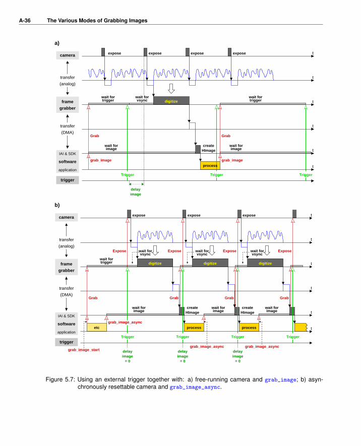
Figure 5.7a shows the timing diagram when using an external trigger together with grab_image and afree-running camera. After the call to grab_image, the image acquisition device waits for the triggersignal. When it appears, the procedure described in the previous section follows: The device waits for thenext image, digitizes it, and transfers it into computer memory; then, the HALCON acquisition interfacetransforms it into a HALCON image and returns the control to the application which processes the imageand then calls grab_image again, which causes the image acquisition device to wait for the next triggersignal.
The (bad) example in figure 5.7a was chosen on purpose to show an unsuitable configuration for usingan external trigger: First of all, because of the free-running camera there is a non-deterministic delaybetween the arrival of the trigger signal and the exposure of the image, which may mean that the objectto be inspected is not completely visible anymore. Secondly, because grab_image is used, triggersignals which arrive while the application is processing an image are lost.
Both problems can easily be solved by using an asynchronously resettable camera together with theoperator grab_image_async as depicted in figure 5.7b.
The C++ example program examples\solution_guide\image_acquisition\cpp\
error_handling_timeout.cpp shows how simple it is to use an external trigger: The connection isopened with ExternalTrigger set to ’true’:
HFramegrabber acqdevice;
acqdevice.OpenFramegrabber(acqname, 1, 1, 0, 0, 0, 0, "default", -1,
"gray", -1, "true", "default", "default", -1, -1);
Then, images are grabbed:
HImage image;
do
{
image = acqdevice.GrabImageAsync(-1);
} while (button == 0);
The example contains a customized error handler which checks whether there is an external trigger; thispart is described in detail in section 6.4.3 on page 45.
Gra
bbin
g
A-36 The Various Modes of Grabbing Images
delayimage
delayimage
= 0
createHImage
createHImage
createHImage
expose
delayimage
= 0
delayimage
= 0
exposeexpose expose expose
IAI & SDK
application
expose
IAI & SDK
application
a)
b)
expose
trigger
frame
grabber
camera
frame
grabber
camera
trigger
t
t
t
t
t
tsoftware
t
t
t
t
t
tsoftware
wait fortrigger
wait forvsync
wait fortrigger
wait forimage
(DMA)
transfer
(analog)
transfer
wait fortrigger
wait forvsync
(DMA)
transfer
(analog)
transfer
Trigger
Trigger
digitize
process
Trigger Trigger
wait forimage
digitize
wait forimage
process
Trigger
process
Trigger
wait forimage
wait forvsync
digitize
Grab
wait forvsync
digitize
Trigger
wait forimage
grab_image_async
grab_image
Grab
Grab
Expose
grab_image
Grab
ExposeExpose Expose
etc
grab_image_startgrab_image_async grab_image_async
GrabGrab
Figure 5.7: Using an external trigger together with: a) free-running camera and grab_image; b) asyn-chronously resettable camera and grab_image_async.

5.3 Acquiring Images From Multiple Cameras A-37
5.2.1 Special Parameters for External Triggers
Most image acquisition interfaces allow to further configure the use of external triggering via the operatorset_framegrabber_param. As mentioned in section 4.2 on page 20, some interfaces allow to enableand disable the external trigger dynamically via the parameter ’external_trigger’. Another usefulparameter is ’grab_timeout’, which sets a timeout for the acquisition process (some interfaces providean additional parameter ’trigger_timeout’ just for triggered grabbing). Without such a timeout, theapplication would hang if for some reason no trigger signal arrives. In contrast, if a timeout is specified,the operators grab_image and grab_image_async only wait the specified time and then return an errorcode or raise an exception, depending on the programming language used. Section 6.4 on page 42 showshow to handle such errors.
Other parameters allow to further specify the form of the trigger signal (’trigger_signal’), e.g.,whether the falling or the rising edge is used as the trigger, select between multiple trigger input lines, oreven filter trigger signals. Some acquisition interfaces also allow to influence the exposure via the triggersignal.
5.3 Acquiring Images From Multiple Cameras
The timing diagrams shown in the previous sections depicted the case of a single camera. Below wediscuss some issues which arise when acquiring images from multiple cameras (see section 3.2 on page12 for possible configurations).
5.3.1 Dynamic Port Switching and Asynchronous Grabbing
If you switch dynamically between multiple cameras connected to a single board as described in sec-tion 3.2.4 on page 14, you must be careful when using grab_image_async: By default, the acquisitioninterface commands the frame grabber board to grab the next image automatically after it received thecurrent image — but before the next call of grab_image_async! If you switched to another camerabefore this call, the frame grabber might already be busy grabbing an image from the first camera.
Some acquisition interfaces solve this problem by providing the parameter’start_async_after_grab_async’ for the operator set_framegrabber_param which allowsto disable the automatic grab command to the frame grabber board.
set_framegrabber_param (AcqHandle, 'start_async_after_grab_async', \
'disable')
Now, all grab commands must be issued explicitly with the operator grab_image_start. The followingcode shows how to switch between cameras in a loop:
Gra
bbin
g

A-38 The Various Modes of Grabbing Images
* switch to camera 0 and grab a first image
set_framegrabber_param (AcqHandle, 'port', Port0)
grab_image_start (AcqHandle, -1)
dev_set_window (WindowHandle0)
grab_image_async (Image0, AcqHandle, -1)
dev_display (Image0)
while (1)
* switch to camera 1 and start a new grab
set_framegrabber_param (AcqHandle, 'port', Port1)
grab_image_start (AcqHandle, -1)
* meanwhile, process image 0
* then get image from camera 1
dev_set_window (WindowHandle1)
grab_image_async (Image1, AcqHandle, -1)
dev_display (Image1)
* switch to camera 0 and start a new grab
set_framegrabber_param (AcqHandle, 'port', Port0)
grab_image_start (AcqHandle, -1)
* meanwhile, process image 1
* then get image from camera 0
dev_set_window (WindowHandle0)
grab_image_async (Image0, AcqHandle, -1)
dev_display (Image0)
endwhile
5.3.2 Simultaneous Grabbing
Some image acquisition interfaces provide special functionality to grab images simultaneously from mul-tiple (synchronized) cameras. Typically, the cameras are connected to a single frame grabber board; someinterfaces also allow to grab simultaneously from cameras connected to multiple boards. As described insection 3.2.5 on page 15, the images are grabbed by a single call to grab_image or grab_image_async,which return them in form of a multi-channel image. Depending on the acquisition interface, it may benecessary to switch on the simultaneous grabbing via the operator set_framegrabber_param.
Please keep in mind that even if a HALCON acquisition interface supports simultaneous grabbing, thismight not be true for every frame grabber board the interface supports! In order to grab multiple imagessimultaneously, a frame grabber board must be equipped with multiple “grabbing units”; for example,an analog frame grabber board must be equipped with multiple A/D converters. Please check this in thedocumentation of your frame grabber board.
Even if a HALCON acquisition interface does not provide the special simultaneous grabbing mode, youcan realize a similar behavior “manually”, e.g., by connecting each (asynchronously resettable) camerato a single frame grabber board and then using a common external trigger signal to synchronize thegrabbing.

Miscellaneous A-39
Chapter 6
Miscellaneous
6.1 Acquiring Images From Standardized Image AcquisitionDevices
Different committees have developed standards for image acquisition interfaces. HALCON supportsseveral of these standards and provides the corresponding interfaces. In particular the standards GenI-Cam, GigE Vision, OpenNI, Video4Linux, DCAM, DirectFile, DirectShow, and Twain are supported.A standardized image acquisition interface is suitable for different image acquisition devices that do notnecessarily have the same set of parameters to adjust during the image acquisition. For some interfaces,e.g, the 1394IIDC interface that follows the DCAM standard, a fixed set of parameters is available andit can be queried for a specific device, which of these parameters are supported by the device. For otherinterfaces arbitrary parameters are allowed. Such interfaces are called “generic”. Examples for genericinterfaces are the GenICamTL interface, which follows the GenTL module of the GenICam standard,and the GigEVision interface that follows the GigE Vision standard. As the parameters for a genericinterface may be arbitrary, the information about the device-specific parameters is not provided with thedescription of the interface but must be queried from the device. For example, if the interface followsthe GenICam standard, the needed information is available in form of an xml file that is typically storedon the device. When calling open_framegrabber, the information is read automatically. The indi-vidual parameter names that are available for the specific device can then be queried with the operatorget_framegrabber_param setting Param to ’available_param_names’. For the returned parameternames further information can be queried. For example, you can query the following parameter valuesfor each parameter name (replace ’name’ by the specific parameter name):
’name_range’: range for the allowed numerical values, in particular, the min-imum allowed value, the maximum allowed value, the incre-ment value, and the default value.
’name_values’: available string values.
’name_description’: short description of the parameter, i.e., a kind of a tool tip.
Additionally, parameter values can be queried that are supported only for some interfaces. The followingparameter values are very common and are used, e.g., by the GenICamTL and the GigEVision interface:
Mis
cella
neou
s

A-40 Miscellaneous
’name_access’: access type, i.e., information to which degree the parametercan be accessed, i.e., can it only be read or also be written?
’name_category’: information to which thematic category of parameters the pa-rameter belongs.
’name_visibility’: information to which group of users the parameter is helpful,i.e., should a beginner try to adjust it, or is it more suitable for’experts’ or even only for ’gurus’?
The HDevelop example program hdevelop\Image\Acquisition\gigevision_parameters.hdev
shows how to query parameters of a GigEVision interface. In particular, after opening the connectionto the specific device with open_framegrabber, the tuple of available device-specific parameter namesis queried using the parameter ’available_param_names’ within get_framegrabber_param. Then,for each of the available parameters, the access type is determined. If the parameter is readable, its valueas well as the range for the numerical values or the available string values are queried.
open_framegrabber (InterfaceName, 0, 0, 0, 0, 0, 0, 'default', -1, \
'default', GenericParam, 'false', 'default', Device, 0, \
-1, AcqHandle)
get_framegrabber_param (AcqHandle, 'available_param_names', ParameterValues)
for Index := 0 to |ParameterValues| - 1 by 1
get_framegrabber_param (AcqHandle, ParameterValues[Index] + '_access', \
ParameterAccess)
* If the parameter is readable, query further information
get_framegrabber_param (AcqHandle, ParameterValues[Index], ParameterValue)
* Note that only one out of the two queries for '_range' and '_values'* is available for each parameter
get_framegrabber_param (AcqHandle, ParameterValues[Index] + '_range', \
ParameterValuesOut)
get_framegrabber_param (AcqHandle, ParameterValues[Index] + '_values', \
ParameterValuesOut)
endfor
close_framegrabber (AcqHandle)
Note that for generic image acquisition interfaces different types of parameters are used: the parame-ters specific for the image acquisition device, the parameters provided by HALCON, and the parametersprovided by the driver. The parameters provided by HALCON are explained with the description of theinterface. All other parameters are queried with get_framegrabber_param setting Param to ’avail-
able_param_names’ as is described above.
6.2 Acquiring Images From Unsupported Image AcquisitionDevices
If you want to use an image acquisition device that is currently not supported by HALCON, i.e., forwhich no HALCON interface exists, there exist two principal ways: First, you can create your ownHALCON acquisition interface; how to do this is described in detail in the Image Acquisition InterfaceProgrammer’s Manual.

6.2 Acquiring Images From Unsupported Image Acquisition Devices A-41
As a very easy to use alternative, you can pass externally created images, i.e., the raw im-age matrix, to HALCON using the operators gen_image1, gen_image3, gen_image1_extern, orgen_image3_extern, which create a corresponding HALCON image. The main difference betweenthe operators gen_image1 and gen_image1_extern and their variants for three-channel images is thatthe former copies the image matrix when creating the HALCON image, whereas the latter doesn’t, whichis useful if you want to realize volatile grabbing as described in section 5.1.3 on page 27.
The C example program examples\solution_guide\image_acquisition\c\
use_extern_image.c shows how to use the operator gen_image1_extern to pass standardgray value images to HALCON. In this case, the image matrix consists of 8 bit pixels (bytes), whichcan be represented by the data type unsigned char. At the beginning, the program calls a procedurewhich allocates memory for the images to be “grabbed”; in a real application this corresponds to theimage buffer(s) used by the image acquisition device SDK.
unsigned char *image_matrix_ptr;
Hlong width, height;
InitializeBuffer(&image_matrix_ptr, &width, &height);
The example program “simulates” the grabbing of images with a procedure which reads images froman image sequence and copies them into the image buffer. Then, the content of the image buffer istransformed into a HALCON image (type byte) via gen_image1_extern. The parameter ClearProcis set to 0 to signal that the program itself takes care of freeing the memory. The created HALCONimage is then displayed. The loop can be exited by clicking into the HALCON window with any mousebutton.
Hobject image;
long window_id;
open_window (0, 0, width, height, 0, "visible", "", (Hlong*)&window_id);
while (!ButtonPressed(window_id))
{
MyGrabImage((const unsigned char **) &image_matrix_ptr);
gen_image1_extern(&image, "byte", (Hlong)width, (Hlong)height,
(long) image_matrix_ptr, (long) 0);
disp_obj(image, window_id);
}
If your image acquisition device supplies images with more than 8 bit pixels, you must adapt boththe data type for the image matrix and the type of the created HALCON image (parameter Type ofgen_image1_extern). In case of color images HALCON expects the image data in form of threeseparate image matrices. Correspondingly, you can create a HALCON image by calling the operatorsgen_image3 or gen_image3_extern with the three pointers to the matrices. Please refer to appendix Aon page 51 for more information about HALCON images in general.
Mis
cella
neou
s

A-42 Miscellaneous
6.3 Grabbing Image Arrays and Preprocessed Image Data
The previous sections described in detail how to acquire images using grab_image orgrab_image_async. With these operators images can be grabbed and, if an image consists of sev-eral channels, the image is grabbed as a multi-channel image (see also appendix A.1 on page 51). Forthe typical color image, this approach is suited very well, as multi-channel images can be further pro-cessed conveniently by many HALCON operators . But sometimes, e.g., if the grabbed data describes3D data rather than a color image, the images are needed in an array instead of a multi-channel image.Then, you can either grab the image as a multi-channel image, access the individual channels with theoperator access_channel, and store the images of the individual channels in an array. Or, which ismore comfortable, you can call the operator grab_data or grab_data_async instead. Both opera-tors immediatley return the grabbed images in an array. Furthermore, they provide the possibility toadditionally grab preprocessed image data like regions, contours, or control data.
Note that grab_data and grab_data_async are not available for all image acquisition interfaces.Typically, they are supported by those interfaces that acquire 3D data or that allow a preprocessingin the camera or the framegrabber. For example, the HDevelop example program hdevelop\Image\
Acquisition\swissranger_simple.hdev shows how to use grab_data to access an array of imagesfrom a SwissRanger interface that contains amongst others the X, Y, and Z images needed to build a3D object model.
for i := 1 to 100 by 1
grab_data (ImageData, Region, Contours, AcqHandle, Data)
count_obj (ImageData, NumImageData)
select_obj (ImageData, ImageX, 1)
select_obj (ImageData, ImageY, 2)
select_obj (ImageData, ImageZ, 3)
select_obj (ImageData, DistanceImage, 4)
select_obj (ImageData, AmplitudeImage, 5)
if (NumImageData > 5)
select_obj (ImageData, ConfidenceImage, 6)
endif
endfor
xyz_to_object_model_3d (ImageX, ImageY, ImageZ, ObjectModel3DID)
6.4 Error Handling
Just as the HALCON acquisition interfaces encapsulate the communication with an image acquisitiondevice, they also encapsulate occurring errors within the HALCON error handling mechanism. How tocatch and react to these errors is described below for HDevelop programs and also for programs usingHALCON’s programming language interfaces.
Some HALCON acquisition interfaces provide special parameters for set_framegrabber_param
which are related to error handling. The most commonly used one is the parameter ’grab_timeout’which specifies when the image acquisition device should quit waiting for an image. The examplesdescribed in the following sections show how to handle the corresponding HALCON error.

6.4 Error Handling A-43
Figure 6.1: Popup dialog in HDevelop signaling a timeout.
Note that all example programs enable the signaling of low level errors via the operator set_system,e.g., in HDevelop syntax via
set_system ('do_low_error', 'true')
In this mode, low level errors occurring in the image acquisition device SDK (or in the HALCON acqui-sition interface) are signaled by a message box.
6.4.1 Error Handling in HDevelop
The HDevelop example solution_guide\image_acquisition\error_handling_timeout.hdev
shows how to handle HALCON errors in an HDevelop program. To “provoke” an error,open_framegrabber is called with ExternalTrigger = ’true’. If there is no trigger, a call tograb_image results in a timeout; HDevelop reacts to this error with the popup dialog shown in fig-ure 6.1 (provided that the display of low level error message boxes is activated via the Preferences
dialog, otherwise the message is only displayed in the Output Console of the Window menu) andstops the execution of the program.
open_framegrabber (AcqName, 1, 1, 0, 0, 0, 0, 'default', -1, 'default', -1, \
'true', 'default', 'default', -1, -1, AcqHandle)
set_framegrabber_param (AcqHandle, 'grab_timeout', 2000)
grab_image (Image, AcqHandle)
HALCON lets you modify the reaction to an error with the operator set_check (in HDevelop:dev_set_check). If you set it to ’˜give_error’, the program does not stop in case of an error butonly stores its cause in form of an error code. To access this error code in HDevelop, you must definea corresponding variable using the operator dev_error_var. Note that this variable is updated aftereach operator call; to check the result of a single operator we therefore recommend to switch back to thestandard error handling mode directly after the operator call as in the following lines:
dev_error_var (ErrorNum, 1)
dev_set_check ('~give_error')grab_image (Image, AcqHandle)
dev_error_var (ErrorNum, 0)
dev_set_check ('give_error')
Mis
cella
neou
s

A-44 Miscellaneous
To check whether a timeout occurred, you compare the error variable with the code signaling a timeout(5322); a list of error codes relating to image acquisition can be found in the Image Acquisition InterfaceProgrammer’s Manual, appendix F on page 93. In the example, the timeout is handled by disabling theexternal trigger mode via the operator set_framegrabber_param (parameter ’external_trigger’).Then, the call to grab_image is tested again.
if (ErrorNum == 5322)
set_framegrabber_param (AcqHandle, 'external_trigger', 'false')dev_error_var (ErrorNum, 1)
dev_set_check ('~give_error')grab_image (Image, AcqHandle)
dev_error_var (ErrorNum, 0)
dev_set_check ('give_error')endif
Now, the error variable should contain the value 2 signaling that the operator call succeeded; for thisvalue, HDevelop provides the constant H_MSG_TRUE. If you get another error code, the program accessesthe corresponding error text using the operator get_error_text.
if (ErrorNum != H_MSG_TRUE)
get_error_text (ErrorNum, ErrorText)
endif
If your image acquisition interface does not provide the parameter ’external_trigger’, you canrealize a similar behavior by closing the connection and then opening it again with ExternalTrigger
set to ’false’.
6.4.2 Error Handling Using HALCON/C
The mechanism for error handling in a program based on HALCON/C is similar to the one in HDevelop;in fact, it is even simpler, because each operator automatically returns its error code. However, if aHALCON error occurs in a C program, the default error handling mode causes the program to abort.
The C example program examples\solution_guide\image_acquisition\c\
error_handling_timeout.c performs the same task as the HDevelop program in the previoussection; if the call to grab_image succeeds, the program grabs and displays images in a loop, which canbe exited by clicking into the window. The following lines show how to test whether a timeout occurred:
set_check ("~give_error");
error_num = grab_image (&image, acqhandle);
set_check ("give_error");
switch (error_num)
{
case H_ERR_FGTIMEOUT:
As you see, in a C program you can use predefined constants for the error codes (see the Image Acquisi-tion Interface Programmer’s Manual, appendix F on page 93, for a list of image acquisition error codesand their corresponding constants).

6.4 Error Handling A-45
6.4.3 Error Handling Using HALCON/C++
If your application is based on HALCON/C++, an exception handling mechanism is provided based onthe class HException, which is described in the Programmer’s Guide, section 5.3 on page 45. Whenevera HALCON error occurs, an instance of this class is created.
The main idea is that you can specify a procedure which is then called automatically withthe created instance of HException as a parameter. How to use this mechanism is ex-plained in the C++ example program examples\solution_guide\image_acquisition\cpp\
error_handling_timeout.cpp, which performs the same task as the examples in the previous sec-tions.
In the example program examples\solution_guide\image_acquisition\cpp\
error_handling_timeout.cpp, the procedure which is to be called upon error is very simple:It just raises a standard C++ exception with the instance of HException as a parameter.
You react to a timeout with the following lines:
try
{
image = acqdevice.GrabImage();
}
catch (HException &except)
{
if (except.ErrorCode() == H_ERR_FGTIMEOUT)
{
acqdevice.SetFramegrabberParam("external_trigger", "false");
As already noted, if your image acquisition interface does not provide the parameter ’exter-
nal_trigger’, you can realize a similar behavior by closing the connection and then opening it againwith ExternalTrigger set to ’false’:
if (except.err == H_ERR_FGTIMEOUT)
{
acqdevice.OpenFramegrabber(acqname, 1, 1, 0, 0, 0, 0, "default",
-1, "gray", -1, "false", "default",
"default", -1, -1);
Note that when calling OpenFramegrabber via the class HFramegrabber as above, the operator checkswhether it is called with an already opened connection and automatically closes it before opening it withthe new parameters.
6.4.4 Error Handling Using HALCON/COM
For error handling with HALCON/COM please refer to the Programmer’s Guide, section 19.6 on page175.
Mis
cella
neou
s

A-46 Miscellaneous
6.4.5 Error Handling Using HALCON/.NET
For error handling with HALCON/.NET (e.g., in C# or Visual Basic .NET applications) please refer tothe Programmer’s Guide, section 16.8 on page 147.
6.5 Callback Functions
With callbacks HALCON applications can be notified of occurences that are defined by different call-back types, e.g., if the exposure has finished or the transfer between camera and computer is complete.Callbacks are available only for specific image acquisition interfaces or devices and are not avail-!able for HDevelop programs but only for the programming languages supported by HALCON!
In practice, first a user-specific callback function must be written that will be called at the occurencedefined by the specific callback type. Note that the function must be written in the selected programminglanguage, i.e., if you use HALCON/C++, the callback function must be implemented in HALCON/C++,too. The function must provide the following parameters: the handle to the image acquisition device, apointer to interface-specific context data, and a pointer to user-specific context data. The specific signa-ture is described in detail with the operator set_framegrabber_callback. This operator is then usedto register the callback function in HALCON. There, the handle to the image acquisition interface andthe pointer to the optional user-specific data must be specified. Additionally, the specific callback typemust be set. Note that not all image acquisition interfaces support callbacks and the callback types varybetween the interfaces that do support them. To check if callbacks are supported by your interface and toquery the specific callback types that are available for it, you can call get_framegrabber_param set-ting the parameter Param to ’available_callback_types’. With get_framegrabber_callback
you can query the callback function and the pointer to the user-specific data set for a specific callbacktype and image acquisition interface.
When implementing the user-specific callback function, you should take care that its execution time isas short as possible, because, if the execution of the user-specific callback function takes too long, thesystem will slow down or the occurence of further user-specific callbacks might be lost. Which caseapplies depends on the way the interface internally handles the synchronization of the callback process.In particular, the synchronization can be based on internally used callbacks or on a mechanism that usesso-called “events”. In the first case, the user-specific callback function is activated by an internally usedcallback function that waits for the user-specific callback function to finish before the next callback typeis processed. This process may slow down the frame rate if the user-specific callback function is verycomplex. In the second case, the interfaces use “events” instead of an internally used callback functionto activate the user-specific callback function. Then, the process does not wait for the user-specificcallback function to finish before it proceeds. Instead, it waits a fixed time after activating the user-specific callback function and then proceeds automatically. This waiting time cannot be controlled bythe user and thus, it might happen for very complex user-specific callback functions that by the time anevent tries to activate the user-specific callback function, the function is still busy and the event is lost.
6.6 Line Scan Cameras
From the point of view of HALCON there is no difference between area and line scan cameras: Bothacquire images of a certain width and height; whether the height is 1, i.e., a single line, or larger does not

6.6 Line Scan Cameras A-47
matter. In fact, in many line scan applications the image acquisition device combines multiple acquiredlines to form a so-called page which further lessens the difference between the two camera types.
The main problem is therefore whether your frame grabber supports line scan cameras. If yes, youcan acquire images from it via HALCON exactly as from an area scan camera. With the parameterImageHeight of the operator open_framegrabber you can sometimes specify the height of the page;typically, this information is set in the camera configuration file. Some HALCON acquisition interfacesallow to further configure the acquisition mode via the operator set_framegrabber_param.
The images acquired from a line scan camera can then be processed just like images from area scancameras. However, line scan images often pose an additional problem: The objects to inspect maybe spread over multiple images (pages). To solve this problem, HALCON provides special opera-tors: tile_images allows to merge images into a larger image, merge_regions_line_scan andmerge_cont_line_scan_xld allow to merge the (intermediate) processing results of subsequent im-ages.
How to use these operators is explained in the HDevelop example program solution_guide\
image_acquisition\line_scan.hdev. The program is based on an image file sequence which isread using the HALCON virtual acquisition interface File; the task is to extract paper clips and calcu-late their orientation. Furthermore, the gray values in a rectangle surrounding each clip are determined.
An important parameter for the merging is over how many images an object can be spread. In theexample, a clip can be spread over 4 images:
MaxImagesRegions := 4
The continuous processing is realized by a simple loop: At each iteration, a new image is grabbed, andthe regions forming candidates for the clips are extracted using thresholding.
while (1)
grab_image (Image, AcqHandle)
threshold (Image, CurrRegions, 0, 80)
The current regions are then merged with ones extracted in the previous image using the operatormerge_regions_line_scan. As a result, two sets of regions are returned: The parameter CurrMerge-dRegions contains the current regions, possibly extended by fitting parts of the previously extractedregions, whereas the parameter PrevMergedRegions contains the rest of the previous regions.
merge_regions_line_scan (CurrRegions, PrevRegions, CurrMergedRegions, \
PrevMergedRegions, ImageHeight, 'top', \
MaxImagesRegions)
connection (PrevMergedRegions, ClipCandidates)
select_shape (ClipCandidates, FinishedClips, 'area', 'and', 4500, 7000)
The regions in PrevMergedRegions are “finished”; from them, the program selects the clips via theirarea and further processes them later, e.g., determines their position and orientation. The regions inCurrMergedRegions are renamed and now form the previous regions for the next iteration.
copy_obj (CurrMergedRegions, PrevRegions, 1, -1)
endwhile
Mis
cella
neou
s

A-48 Miscellaneous
a)
b)
c)
4
32
1
5 6
3
3
4
1
2
1
2
Figure 6.2: Merging regions extracted from subsequent line scan images: state after a) 2, b) 3, c) 4images (large coordinate system: tiled image; small coordinate systems: current image ormost recent image).
Note that the operator copy_obj does not copy the regions themselves but only the corresponding HAL-CON objects, which can be thought of as references to the actual region data.
Before we show how to merge the images let’s take a look at figure 6.2, which visualizes the wholeprocess: After the first two images CurrMergedRegions contains three clip parts; for the first one apreviously extracted region was merged. Note that the regions are described in the coordinate frame ofthe current image; this means that the merged part of clip no. 1 has negative coordinates.
In the next iteration (figure 6.2b), further clip parts are merged, but no clip is finished yet. Note thatthe coordinate frame is again fixed to the current image; as a consequence the currently merged regionsseem to move into negative coordinates.
After the fourth image (figure 6.2c), clips no. 1 and 2 are completed; they are returned in the parameterPrevMergedRegions. Note that they are still described in the coordinate frame of the previous image(depicted with dashed arrow); to visualize them together with CurrMergedRegions they must be movedto the coordinate system of the current image using the operator move_region:
move_region (FinishedClips, ClipsInCurrentImageCoordinates, \
-ImageHeight, 0)

6.6 Line Scan Cameras A-49
Let’s get back to the task of merging images: To access the gray values around a clip, one must mergethose images over which the PrevMergedRegions can be spread. At the beginning, an empty image iscreated which can hold 4 images:
gen_image_const (TiledImage, 'byte', ImageWidth, \
ImageHeight * MaxImagesRegions)
At the end of each iteration, the “oldest” image, i.e., the image at the top, is cut off the tiled image usingcrop_part, and the current image is merged at the bottom using tile_images_offset:
crop_part (TiledImage, TiledImageMinusOldest, ImageHeight, 0, \
ImageWidth, (MaxImagesRegions - 1) * ImageHeight)
concat_obj (TiledImageMinusOldest, Image, ImagesToTile)
tile_images_offset (ImagesToTile, TiledImage, [0, \
(MaxImagesRegions - 1) * ImageHeight], [0,0], [-1, \
-1], [-1,-1], [-1,-1], [-1,-1], ImageWidth, \
MaxImagesRegions * ImageHeight)
As noted above, the regions returned in PrevMergedRegions are described in the coordinate frame ofthe most recent image (depicted with dashed arrows in figure 6.2c); to extract the corresponding gray val-ues from the tiled image, they must first be moved to its coordinate system (depicted with longer arrows)using the operator move_region. Then, the surrounding rectangles are created using shape_trans, andfinally the corresponding gray values are extracted using add_channels:
move_region (FinishedClips, ClipsInTiledImageCoordinates, \
(MaxImagesRegions - 1) * ImageHeight, 0)
shape_trans (ClipsInTiledImageCoordinates, AroundClips, 'rectangle1')add_channels (AroundClips, TiledImage, GrayValuesAroundClips)
Mis
cella
neou
s

A-50 Miscellaneous

HALCON Images A-51
Appendix A
HALCON Images
In the following, we take a closer look at the way HALCON represents and handles images. Of course,we won’t bother you with details about the low-level representation and the memory management; HAL-CON takes care of it in a way to guarantee optimal performance.
A.1 The Philosophy of HALCON Images
There are three important concepts behind HALCON’s image objects:
1. Multiple channelsTypically, one thinks of an image as a matrix of pixels. In HALCON, this matrix is called achannel, and images may consist of one or more such channels. For example, gray value imagesconsist of a single channel, color images of three channels.
The advantage of this representation is that many HALCON operators automatically process allchannels at once; for example, if you want to subtract gray level or color images from another,you can apply sub_image without worrying about the image type. Whether an operator pro-cesses all channels at once can be seen in the parameter description in the reference manual:If an image parameter is described as (multichannel-)image or (multichannel-)image(-array) (e.g., the parameter ImageMinuend of sub_image), all channels are processed; if it isdescribed as image or image(-array) (e.g., the parameter Image of threshold), only the firstchannel is processed.
For more information about channels please refer to appendix A.3.2 on page 53.
2. Various pixel typesBesides the standard 8 bit (type byte) used to represent gray value image, HALCON allowsimages to contain various other data, e.g. 16 bit integers (type int2 or uint2) or 32 bit floatingpoint numbers (type real) to represent derivatives.
Most of the time you need not worry about pixel types, because HALCON operators that outputimages automatically use a suitable pixel type. For example, the operator derivate_gausscreates a real image to store the result of the derivation. As another example, if you connect
HA
LCO
NIm
ages

A-52 HALCON Images
to an image acquisition device selecting a value > 8 for the parameter BitsPerChannel, asubsequent grab_image returns an uint2 image.
3. Arbitrarily-shaped region of interestBesides the pixel information, each HALCON image also stores its so-called domain in form of aHALCON region. The domain can be interpreted as a region of interest, i.e., HALCON operators(with some exceptions) restrict their processing to this region.
The image domain inherits the full flexibility of a HALCON region, i.e., it can be of arbitraryshape and size, can have holes, or even consist of unconnected points. For more informationabout domains please refer to appendix A.3.3.
The power of HALCON’s approach lies in the fact that it offers full flexibility but does not require youto worry about options you don’t need at the moment. For example, if all you do is grab and processstandard 8 bit gray value images, you can ignore channels and pixel types. At the moment you decideto use color images instead, all you need to do is to add some lines to decompose the image into itschannels. And if your camera / frame grabber provides images with more than 8 bit pixel information,HALCON is ready for this as well.
A.2 Image Tuples (Arrays)
Another powerful mechanism of HALCON is the so-called tuple processing: If you want to processmultiple images in the same way, e.g., to smooth them, you can call the operator (e.g., mean_image) oncepassing all images as a tuple (array), instead of calling it multiple times. Furthermore, some operatorsalways return image tuples, e.g., gen_gauss_pyramid or inspect_shape_model.
Whether an operator supports tuple processing can be seen in the parameter description in the referencemanual: If an input image parameter is described as image(-array) or (multichannel-)image(-array) (e.g., the parameter Image of mean_image), it supports tuple processing; if it is described asimage or (multichannel-)image (e.g., the parameter Image of find_bar_code), only one image isprocessed.
For information about creating or accessing image tuples please refer to appendix A.3.6.
A.3 HALCON Operators for Handling Images
Below you find a brief overview of operators that allow to create HALCON images or to modify “tech-nical aspects” like the image size or the number of channels.
A.3.1 Creation
HALCON images are created automatically when you use operators like grab_image or read_image.You can also create images from scratch using the operators listed in the HDevelop menu Operators
. Image . Creation, e.g., gen_image_const or gen_image1_extern (see also section 6.2 on page40).

A.3 HALCON Operators for Handling Images A-53
A.3.2 Channels
Operators for manipulating channels can be found in the HDevelop menu Operators . Image . Chan-nel. You can query the number of channels of an image with the operator count_channels. Channelscan be accessed using access_channel (which extracts a specified channel without copying), im-age_to_channels (which converts a multi-channel image into an image tuple), or decompose2 etc.(which converts a multi-channel image into 2 or more single-channel images). Vice versa, you can cre-ate a multi-channel image using channels_to_image or compose2 etc., and add channels to an imageusing append_channel.
A.3.3 Domain
Operators for manipulating the domain of an image can be found in the HDevelop menu Operators .Image . Domain. Upon creation of an image, its domain is set to the full image size. You can set it toa specified region using change_domain. In contrast, the operator reduce_domain takes the originaldomain into account; the new domain is equal to the intersection of the original domain with the specifiedregion. Please also take a look at the operator add_channels, which can be seen as complementary toreduce_domain.
A.3.4 Access
Operators for accessing information about a HALCON image can be found in the HDevelop menu Op-
erators . Image . Access. For example, get_image_pointer1 returns the size of an image and apointer to the image matrix of its first channel.
A.3.5 Manipulation
You can change the size of an image using the operators change_format or crop_part, or other op-erators from the HDevelop menu Operators . Image . Format. The menu Operators . Image .Type-Conversion lists operators which change the pixel type, e.g., convert_image_type. Opera-tors to modify the pixel values, can be found in the menu Operators . Image . Manipulation, e.g.,paint_gray, which copies pixels from one image into another.
A.3.6 Image Tuples
Operators for creating and accessing image tuples can be found in the HDevelop menu Operators
. Object . Manipulation. Image tuples can be created using the operators gen_empty_obj andconcat_obj, while the operator select_obj allows to access an individual image that is part of atuple.
HA
LCO
NIm
ages

A-54 HALCON Images

Parameters Describing the Image A-55
Appendix B
Parameters Describing the Image
When opening a connection with open_framegrabber, you can specify the desired image format, e.g.,its size or the number of bits per pixel, using its nine parameters, which are described in the following.
B.1 Image Size
The following 6 parameters influence the size of the grabbed images: HorizontalResolution andVerticalResolution specify the spatial resolution of the image in relation to the original size. Forexample, if you choose VerticalResolution = 2, you get an image with half the height of the originalas depicted in figure B.1b. Another name for this process is (vertical and horizontal) subsampling.
a)
b)
c)
d)
Figure B.1: The effect of image resolution (subsampling) and image cropping (ImageWidth = 200,ImageHeight = 100, StartRow = 50, StartColumn = 100): a) HorizontalResolution (HR) =VerticalResolution (VR) = 1; b) HR = 1, VR = 2; c) HR = 2, VR = 1; d) HR = VR = 2.
Imag
eP
aram
eter
s

A-56 Parameters Describing the Image
With the parameters ImageWidth, ImageHeight, StartRow, and StartColumn you can grab only apart of the (possibly subsampled) image; this is called image cropping. In figure B.1, the image part tobe grabbed is marked with a rectangle in the original (or subsampled) image; to the right, the resultingimage is depicted. Note that the resulting HALCON image always starts with the coordinates (0,0),i.e., the information contained in the parameters StartRow and StartColumn cannot be recovered fromthe resulting image.
Depending on the involved components, both subsampling and image cropping may be executed atdifferent points during the transfer of an image from the camera into HALCON: in the camera, in theframe grabber, or in the software. Image cropping in the camera or in the framegrabber is also calledhardware cropping, whereas image cropping on the software side is called software cropping. Pleasenote that subsampling and image cropping do not necessarily have a direct effect on the performancein form of a higher frame rate. In particular, for analog cameras the frame rate is in most cases notaffected. In contrast, for digital cameras, e.g., hardware cropping often leads to a faster transfer and ahigher frame rate. Subsampling or cropping on the software side has no effect on the frame rate; besides,you can achieve a similar result using reduce_domain. If the frame grabber executes the subsamplingor cropping you may get a positive effect if the PCI bus is the bottleneck of your application and preventsyou from getting the full frame rate. Some acquisition interfaces allow dynamic image cropping via theoperator set_framegrabber_param.
Note that HALCON itself does not differentiate between area and line scan cameras as both produceimages – the former in form of frames, the latter in form of so-called pages created from successivelines (number specified in the parameter ImageHeight). Section 6.6 on page 46 contains additionalinformation regarding the use of line scan cameras.
B.2 Image Data
The parameters described in the previous sections concentrated on the size of the images. The imagedata, i.e., the data contained in a pixel, is described with the parameters BitsPerChannel and Col-
orSpace. To understand these parameters, a quick look at HALCON’s way to represent images is nec-essary: A HALCON image consists of one or more matrices of pixels, which are called channels. Grayvalue images are represented as single-channel images, while color images consist of three channels,e.g., for the red, green, and blue part of an RGB image. Each image matrix (channel) consists of pixels,which may be of different data types, e.g., standard 8 bit (type byte) or 16 bit integers (type int2 oruint2) or 32 bit floating point numbers (type real). For detailed information about HALCON imagesplease refer to appendix A on page 51.
The two parameters correspond to the two main aspects of HALCON images: With the parameter Col-orSpace, you can select whether the resulting HALCON image is to be a (single-channel) gray valueimage (value ’gray’) or a (multi-channel) color image (e.g., value ’rgb’). The parameter BitsPer-Channel specifies how many bits are transmitted per pixel per channel from the frame grabber to thecomputer; the pixel type of the HALCON image is then chosen to accommodate the transmitted numberof pixels.
For example, if a frame grabber is able to transmit 10 bit gray value images, select ColorSpace =’gray’ and BitsPerChannel = 10 and you will get a single-channel HALCON image of the type’uint2’, i.e., 16 bit per channel. Another example concerns RGB images: Some frame grabbers allowthe values 8 and 5 for BitsPerChannel. In the first case, 3 × 8 = 24 bit are transmitted per pixel, while

B.2 Image Data A-57
in the second case only 3 × 5 = 15 (padded to 16) bit are transmitted; in both cases, a three-channel’byte’ image results.
Imag
eP
aram
eter
s

A-58 Parameters Describing the Image

Object Appearance A-59
Appendix C
Object Appearance
The previous chapters showed you how to acquire images. This appendix looks at the step that precedesthe image acquisition, i.e., it provides you with hints how to setup your vision system so that the acquiredimages contain useful and correct information. For a correct measurement result the different compo-nents involved in the process of taking images have to be considered. These are first of all the object ofinterest, the light that makes the object visible, the camera, which stores the spatially assigned intensitiesof incoming light, and the geometrical relation between the camera and the object of interest. Further,the individual components consist of different single components, e.g., the camera comprises a lens anda CCD chip. All the involved components yield sources for errors, e.g., caused by lens distortions or thedigitalization process.
For all machine vision tasks and especially for highly accurate measuring you should be aware of theerror sources that are attached to your specific equipment and of their influence on the appearance of theobjects of interest in the image. A correct image analysis is only possible if the features of interest areclearly visible and for many tasks also geometrically correct. Thus, we here discuss the
• lighting conditions (appendix C.1), which control the visibility of the object, and
• the geometrical relations between camera and object (appendix C.2), which influence the geomet-rical appearance of the objects in the image and control the further processing of the image.
C.1 Lighting
The success of an image analysis task, especially for highly accurate measuring purposes depends onthe visibility of the objects of interest in the image. To obtain images with clearly visible objects, thelighting conditions during image acquisition have to be considered carefully. Dependent on the surfaceof the object and the direction of the light, some parts of the object may reflect more light than othersso that the image does not necessarily map the actual object outlines but also reflections and shadows.With bad lighting conditions, too sparse or too much light is received by the camera, which leads to lowcontrasts at the object borders at least in parts of the image. The task to acquire images that represent theobjects of interest as clear edges or homogeneous regions is rather demanding and involves a certain part
App
eara
nce

A-60 Object Appearance
of intuition. This section summarizes some basic knowledge about lighting and tries to convey to you afeeling for choosing the right lighting conditions for your specific task. In detail, it goes deeper into
• the reflection properties of the object and
• the characteristics of the light source.
C.1.1 Reflection Properties of the Object
Before selecting a specific light source, the specific characteristics of the objects that are to be inspectedhave to be considered. Dependent on an object’s surface light is differently reflected. We differentiatetwo extreme reflection behaviors:
• specular reflection and
• diffuse reflection.
With specular reflection a ray of light is reflected with almost full intensity into a single direction (seefigure C.1, left). Specular reflection is dominant for objects with a low surface roughness like a mirroror plain steel.
With diffuse reflection a ray of light is reflected as several rays of light with less intensity but variousdirections (see figure C.1, right). Diffuse reflection is dominant for objects with a high surface roughnesslike a sheet of paper or sand blasted surfaces.
Generally, objects can not clearly be assigned to one of the two reflection behaviors but lie somewhere inbetween. Some objects have a rather luminous surface and react mainly with specular reflection, whereasobjects with a rather dull surface react mainly with a diffuse reflection.
For an object that reacts mainly with specular reflection, the intensity of the reflected light is ratherstrong but due to its limited direction the object’s visibility in the image heavily depends on the angleof incidence the ray of light comes from. To increase the chance that the reflected light hits the cameralense in a way the object is clearly mapped in the image, a diffuse light source is recommended. Then,light waves come from and therefore are reflected to different directions.
For an object that reacts mainly with a diffuse reflection less light is reflected, but, as the light wavesare reflected into several directions, the visibility of the object does not depend that much on the exactposition of the light source. The following section gives a brief overview of basic types of light sourcesand the influence of their position in relation to the camera and object.
C.1.2 Characteristics of the Light Source
Knowing the characteristics of the object, the light sources and their positions in relation to the objectand camera positions have to be selected. To obtain clear-cut edges without disturbing reflections youshould not rely on day light but use controlled light. In particular, when taking several images the lightingconditions additionally should not change over time. The characteristics of the lighting can be split into
• the specific type of light source, based on the direction the light waves are propagated to, and

C.1 Lighting A-61
Figure C.1: The two (extreme) types of reflection: (left) specular reflection, (right) diffuse reflection.
• the spatial relation between light source, object, and camera.
Similar to the reflection properties of object surfaces, light sources can produce light that is limited tospecific directions or light that emanates into different directions. We differentiate between
• directed light and
• diffuse light.
Directed light is described by rays of light following a defined direction. This may be a single pointlight that emanates concentric light when placed near the object and almost parallel light when placedfar away from the object (see figure C.2, left), but also a telecentric light for which the rays of light areadjusted into exactly parallel directions using a collimator lense (see figure C.2, middle). As all raysof light come from and are reflected to similar directions, strong shadows and reflections may occur.For non-flat objects a telecentric light may be more suitable because a point light may lead to smallperspective distortions. With a telecentric light the 2D outline of the object in the image corresponds tothe cross-section of the 3D object and the size of the object in the image is independent of the distancebetween the camera and the object. But note that telecentric light is mainly suited for small objects as thelight only hits the whole object to be measured if the object is smaller or the same size as the diameterof the lense.
Diffuse light scatters the rays of light, so that an object is lighted from several directions. That way, strongshadows and reflections on the object can be minimized. In figure C.2 the diffuse light is illustrated asa single point light source that is scattered into several rays of light with different directions using adiffuser. In practice, several diffuse light sources are placed at different positions, e.g., in form of a ringlight, to disperse the light as much as possible.
Besides the propagation of the light waves seen from the light source, the direction of light seen fromthe object-camera unit has to be considered for a successful image analysis. Figure C.3 illustrates thedifferent lighting methods. They are coarsely differentiated into
• front light and
• back light.
Front light is used for all objects for which the structure of the surface or any components on the surfaceare of interest, e.g., if scratches in the surface of an object are searched for or if several object parts areto be investigated, e.g., the different components of a board. Front light can be differentiated into
App
eara
nce

A-62 Object Appearance
Diffuse lightDirected point light Directed telecentric light
Light sourceLight source
DiffuserCollimator lens
Object
Light source
Object Object
Figure C.2: Directed and diffuse light: (left) point light, (middle) telecentric light, and (right) diffuse light.
Coaxial
Camera ObjectLight source
Front light Back light
Lightfield Darkfield
Figure C.3: Light sources differentiated due to their spatial relation to object and camera.
• lightfield lighting (including coaxial lighting) and
• darkfield lighting.
With a lightfield lighting the light approximately hits the object surface in a right angle. A special caseof a lightfield lighting is the coaxial lighting, which emanates directly from the direction of the cameralense. The light of a darkfield lighting comes from the side, i.e., it hits the object approximately parallelto its surface. Lightfield lighting is the standard lighting that is used for most applications in machinevision, whereas darkfield lighting is needed to highlight object parts that are not visible when lightedfrom above, e.g., relief structures in the object’s surface.

C.2 Geometry A-63
Back light is used if the outer contour of the object gives the relevant information. The light source isplaced behind the object and the object is mapped to the image as a homogeneous dark region against alight background. Opposite to images with widespread gray values, such a ’binary’ image is rather easyto process.
Dependent on the object’s surface and your specific task, you combine front or back light with a directedor diffuse light source. The list of light sources introduced here does not claim to be complete, but triesto convey to you a first impression on the complexity of the lighting task. To get more information aboutthese and further light sources, e.g., also about polarized light or x-rays, we recommend to read morecomprehensive literature with the specific focus on lighting.
C.2 Geometry
The lighting conditions are important to obtain clearly visible objects in the image. To obtain geometri-cally correct images of the objects of interest, we additionally have to consider the geometrical conditionsbetween the camera and the object of interest during the image acquisition. The geometrical correctnessof the object’s representation in the image depends on various influences like the used equipment and thegeometrical relation between the camera and the object plane. The geometrical distortions with the mostinfluence are lense distortions and perspective distortions. These are described in detail in the SolutionGuide III-C, section 3.4 on page 91. There, you also get detailed information about the techniques tocompensate both distortions, in particular using camera calibration and a following transformation ofeither the image, a contour, or a set of image points into world coordinates. The intention of this sectionis to give you the basic information about the relation between camera and object and thus help you toplan the right camera position for your specific task.
Two main concepts for the relation between the pose (position and orientation) of a camera and the poseof the object are relevant for measuring in an image:
• the orthogonal view and
• the oblique view.
In the orthogonal view the camera looks at the object plane at a right angle (see figure C.4, left). Thus,for a flat object and a normal lense the length of a line’s representation in the image corresponds to thelength of the corresponding real line multiplied by a unique scale factor. For non-flat objects, due toperspective distortions a normal lense may cause small distortions at the border of the object, dependentalso on the position of the object in the image. These distortions can be avoided using a camera with atelecentric lense. In contrast to the telecentric lense used for directing the light rays of a telecentric lightsource, the telecentric lense of a camera does not send but receive parallel rays of light. But similar tothe telecentric light, a telecentric lense in a camera is mainly suited for small objects as the whole objectis only mapped completely in the image if the object is smaller or the same size as the diameter of thelense.
The oblique view is used if limited space does not allow for a setup with an orthogonal view. Here,the angle between the camera and the object plane can be arbitrary (see figure C.4, right). The obliqueview leads to a perspectively distorted geometry of the image content. Thus, the length of a line in theimage can not be translated directly to the length of the real object. A transformation is necessary that
App
eara
nce

A-64 Object Appearance
Resulting image
Oblique viewOrthogonal view
Resulting image
90° 60°
Figure C.4: The two views on a plane: (left) orthogonal view and (right) oblique view.
reconstructs the geometry of the orthogonal case. The parameters needed for the transformation can beobtained by calibrating the camera (see Solution Guide III-C).

Index A-65
Index
acquire image in volatile mode, 27acquire image with asynchronously resettable
camera, 27, 33acquire image(s), 25acquire image(s) continuously, 31acquire image(s) from multiple cameras simul-
taneously, 38acquire image(s) in real time, 29acquire image(s) with external trigger, 35
back lighting, 60
callback function, 46channel, 51coaxial lighting, 60connect to multiple image acquisition boards,
12connect to multiple image acquisition ports, 14connect to single camera, 12
darkfield lighting, 60diffuse lighting, 60diffuse reflection, 60directed lighting, 60domain (ROI), 52
error handling for image acquisition, 42
front lighting, 60
grab image arrays or preprocessed image data,42
image, 51image acquisition interface, 7image array, 52image size, 55
lightfield lighting, 60lighting (illumination), 59
non-real-time image acquisition, 25
open image acquisition device, 11open image acquisition device for port switch-
ing, 14open image acquisition device for simultaneous
grabbing, 15
pixel data, 56pixel type, 51
real-time image acquisition, 25
specular reflection, 60
unsupported image acquisition device, 40use line scan camera, 46use standardized image acquisition interfaces,
39
Inde
x

A-66 Index