solidworks - california state university, northridgesaw78981/paper.pdfsolidworks shawna wise 1....
TRANSCRIPT
Solidworks
Shawna Wise
1. INTRODUCTION
Could a skydiver, whose parachute failed to open, hit one side of a playground seesaw and send
a small girl, sitting on the other side, flying seven stories high and survive? As unlikely as it is
to actually get the answer to this question, the software called SolidWorks Simulation can get the
answer. This question was explored on MythBusters in the 2009 episode ”Seesaw Saga”. The
MythBusters used this program to build a seesaw that maximized the energy transferred from the
falling skydiver to the small girl and kept the seesaw intact. Jamie Hyneman, the main mythbuster,
explains why they used SolidWorks software in this episode:
But why scribble when you’ve got the software to test the concept?... The beauty of
something like this [SolidWorks software] is that it really allows me to push the limits of
the material in the design because it doesn’t matter if the design breaks in the computer.
I’ll just pull up another one and change it a little bit and try it again. And that way, by
the time I get around to building the real thing, I already know it’s gonna work.
MythBusters shows us just one example of how SolidWorks software may be implemented. It
is used in many industries such as: Architectural Design and Engineering, Telephone Equipment
Manufacturing, Professional Services, Communications Equipment, etc. If MythBusters can build
a virtual seesaw, test it for weaknesses, and manipulate it to achieve the maximum energy transfer,
then imagine all the possibilities of this software for many different companies.
2. HISTORY
Companies save time and money by using computers to build, view and test models of products. This
helps to perfect products to reduce physical model types. The best way engineers can accomplish
this is by using what is called 3D solid modelling. Using 3D solid modeling before SolidWorks was
tedious and expensive because the engineers had to calculate every element by hand. SolidWorks
created the software that combined 3D solid modeling with the ease of use with the desktop making it
6ACM Journal Name, Vol. 1, No. 1, November 2010, Pages 1–0??.

2 · Shawna Wise
more intuitive and accessible. In 1993, the founder of SolidWorks, Jon Hirschtick, recruited a group
of engineers with the specific purpose of making 3D Computer Aided Design (CAD) technology
more accessible to engineers, drafters and the common designers around the world. They did this by
developing the first 3D CAD technology that ran on the Windows platform. They also made it more
affordable by creating technology that does not require expensive hardware and software to operate.
The first release of SolidWorks software was in 1995. Within two months of its release, it was winning
accolades for ease-of-use, allowing more engineers, drafters and designers than ever before to take
advantage of 3D CAD in bringing their product designs to life. In 1997, global life cycle technol-
ogy giant Dassault Systemes S.A. took notice, acquiring SolidWorks for 310 million dollars in stock.
Today, SolidWorks offers a complete toolset to create, simulate, publish and manage data. This
allows users to maximize productivity of their engineering resources. While solving complex sim-
ulations such as vibration or impact, SolidWorks Simulation makes it easy to validate whether or
not your design is correct. The most unique idea of SolidWorks is that the user can access the
full potential of the software without needing a Ph.d in Finite Element Analysis (FEA). Matching
this theme, SolidWorks data management distributes as soon as ten days from ordering, allowing
organizations to capitalize on new opportunities faster.
3. BASIC IDEA
The way that SolidWorks Simulation operates is by taking a complicated object with forces applied
and breaking it up into a multitude of computationally simpler pieces. The program then calculates
the effects of the forces on each piece. To understand this let’s take the most basic example of a
force applied on an object; one force applied on a simple one dimensional bar. All objects, even the
very stiff and solid ones, are considered springs.
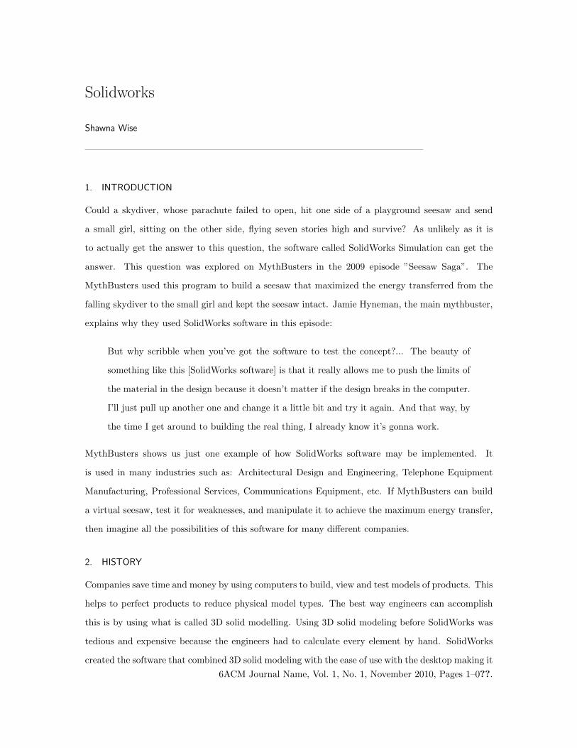
Let’s fix the bar to a wall and pull on one side. The problem with this model is that we have
an infinite number of places to calculate the effects of the force. In order to simplify calculations,
the bar must be divided into two equal sections. Each of the two parts has a node(a reference point
for calculations) at each end and each node has a force being applied to it. In total, there are now
three nodes and three forces on the bar. The model is now essentially two springs, each having a
spring constant ki, the spring’s stiffness. When the spring is pulled each node travels a distance
ACM Journal Name, Vol. 1, No. 1, November 2010.
Solidworks · 3
called the displacement uj . With all of these conditions the picture will look something like this:
Now if each force is solved for using the laws of physics the result is:
F1 = k1(u1 − u2) (1)
F2 = k1(u2 − u1) + k2(u2 − u3) (2)
F3 = k2(u3 − u2) (3)
By simple algebraic laws, these equations can be transformed. Combining the equations to make a
mathematical statement in matrix form, will look like this:F1
F2
F3
=
k1 −k1 0
−k1 k2 + k1 −k2
0 −k2 k2
u1
u2
u3
Since in this example the left side of the bar is fixed, this means the displacement for u1 will be 0.
So it is said that u1 is given to be 0. The F3 will be equal to the force pulled with. So it is also
considered a ”given value”. The [K] matrix can be found by plugging in the stiffness of each spring.
Now the software can take these ”given” values and the matrix equation to fill in the rest of the F ’s
and u’s in the matrix. Once all of these variables are found, the software can use this information
to test for other things such as strain on the bar at each node.
This basic example can be applied to any figure made of any material, and in up to three-dimensions.
For solid objects each u, displacement, from the 1D model becomes directional components ux, uy, uz
ACM Journal Name, Vol. 1, No. 1, November 2010.

4 · Shawna Wise
in a 3D model. Keep in mind this will also make each cut section into a three-dimensional piece
with a node on each corner of the piece. Therefore, any object can be cut into many fragments and
the program will calculate the displacement and force on each node for each fragment. Instead of
companies building the prototype they can virtually test multiple conditions.
4. STATIC LOADING
There are 8 different studies in the SolidWorks program: static, frequency, buckling, thermal, drop
test, fatigue, non-linear dynamic and linear dynamic. We will look in depth into the most basic of
these studies, Static Loading, and briefly into the other studies. A static load, also known as a dead
load, is a non-varying load which studies the pressure that is exerted by the weight of a mass at rest.
For example, a beam bridge is a fixed object with points each having a weight, pressure and force
acting on them. Also, this study is not dependent on the change in time. It is simply looking at the
object at one point in time and will not consider what happens over a period of time. So in this
example things such as cars passing over the bridge, people walking over, etc would not considered.
Now let’s explore how the static load study works.
The calculations are similar to the Basic Idea looked at earlier, however they will be extended
along the parameters for a more general idea. Let’s look at a one-dimensional model such as a rail.
In this model, consider only a force that would extend or contract the rail. On the rail we have
two nodes; one on each end. In order to calculate the stress on the rail at the nodes, these three
equations are needed to compute the information.
Hooke’s Law: [K]~u = ~F (4)
Cauchy Strain Equation: ε =∆l
l(5)
Elasticity Equation: σ = Eε (6)
To determine the stresses and strains on the nodes start with finding the stiffness, displacement,
and force. First, it is important to find The Global Stiffness Matrix which is a constant matrix [K].
There are two things that make up the terms of [K]. One, the geometry of where the nodes fall and
how they are connected to each other determines where the terms go. Two, the material properties
ACM Journal Name, Vol. 1, No. 1, November 2010.
Solidworks · 5
tell the user what the magnitude of the terms are. The absolute displacement vector is ~u. The force
vector exerted on the node is ~F . Each situation always has at least the displacement of one node and
the force applied on another node. The software uses this information to fill in the missing forces
and displacements on the rest of the nodes using an equilibrium equation called Hooke’s Law.Where
[K]~u is the spring’s internal force and ~F is the external force on the node.
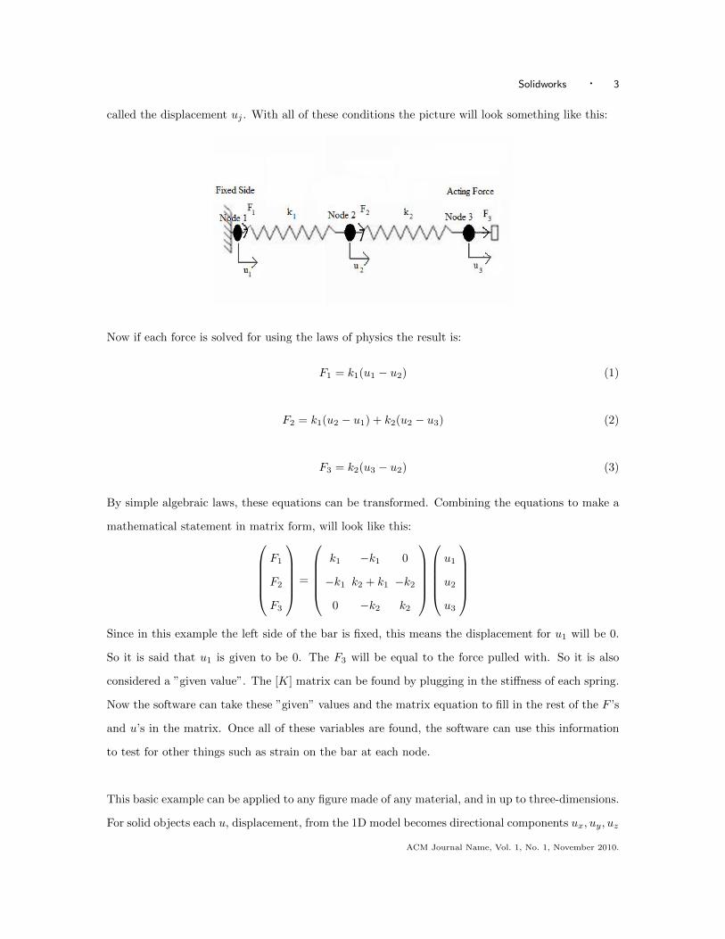
Now that displacement has been established strain ε can be calculated using the Cauchy Strain
equation for each node. For example, in the following picture, the top of the object is fixed and the
bottom has a force applied to it which is the weight. The natural length is the l and the change in
length is the ∆l.
Once the strain has been computed it is used within the Elasticity equation (σ = Eε) to find the
stress σ on the nodes. In the Elasticity equation strain is proportional to stress. The E represents
Young’s Elastic Modulus. Once the stress has been calculated it can be compared to the yield stress
σy. If the σ > σy then there is failure. Ideally the σ < σy so that the material does not bend,
corrupt or fail. In this particular problem there are only two nodes and one force, but this can be
expanded by breaking up the rail into 10 or 100 or 1000 or more pieces where each piece has nodes.
This would allow for a more accurate stress test of the whole rail at each sectioned piece of the rail.
Each piece can be tested to make sure no part of the rail would have a stress greater than the yield
stress.
Now apply this same concept to a complex object with the nodes able to move in any of the
x, y, z directions. This can very quickly become a complex problem with hundreds of nodes and
ACM Journal Name, Vol. 1, No. 1, November 2010.
6 · Shawna Wise
bars to test. The good thing is that the software does all of this for the user. However, the more
nodes and terms partitioned, the more costly the computation. The more partitions of an object,
thus creating more nodes, requires more time and advanced hardware. SolidWorks is considered an
advanced software, in that it does not require powerful hardware to run these computations.
5. FREQUENCY AND BUCKLING
In frequency, a period time is taken into consideration. The software examines situations such as the
deformation of an object due to vibrations over time. A real life example of a prototype needing this
kind of software would be the Tacoma Narrows Bridge in Tacoma, Washington. This bridge became
notorious for large movements during high winds. On November 7, 1940, with a wind velocity of
about 60 kph, the bridge began twisting and oscillating violently. The bridge was twisting about 45
degrees in two waves, and oscillating up and down one meter in nine waves. The oscillations reached
8 meters as the bridge tore itself apart. Problems like this are what the software is used to prevent.
Another classic example of frequency is a tuning fork. The software modifies the length, spacing
and material of a tuning fork to acquire the desired frequency.
Buckling deals with compression for which time is considered as a factor. An example is a building’s
columns. Engineers would use Euler’s critical load equation to determine when a column will fail.
Euler’s Critical Load Equation: Pcr =π2EI
L3ef
(7)
I is the least area moment of inertia. However, rectangular beams have different inertia values de-
pending on what dimension you choose for the height. Lef is the effective length and is dependent
on how the column is secured. Lef = KL where L is the length or height of the column and K is the
constant depending on how the column is secured. There are four ways to secure or rather support
a column: pinned-pinned, fixed-fixed, pinned-fixed, fixed-free. The constants for each are as follows:
pinned-pinned K = 1, fixed-fixed K = .65, pinned-fixed K = .86 and fixed-free K = 2.1. Columns
are classified as short, intermediate or long depending on the slenderness ration. Slenderness is Ldmin
where dmin is the smallest length of the cross-section.
ACM Journal Name, Vol. 1, No. 1, November 2010.

Solidworks · 7
In both of these studies the software uses the free vibration equation:
md2u
dt2+ ku = 0 (8)
To simplify this equation a trigonometric function of time is plugged into u. For this example let
u = φsin(ωt). This makes the first derivative dudt = φωcos(ωt) and the second derivative d2u
dt2 =
−φω2cos(ωt). When solved this new derived equation will be the eigenvalue problem that the
software uses:
φ(k − ω2m) = 0 (9)
6. DROP TEST
The drop test finds the stresses in an object after it collides with a mass such as the ground. This
study allows the user to answer questions about their product such as: where the product can break
if it falls, maximum velocity at the point of impact which the object can withstand, which angles of
impact are more damaging, the acceleration at impact and how extreme the shock is on the object.
Drop test can not move the object in several directions or rotations. Drop Test uses the same free
vibration equation except it is not equal to zero:
md2u
dt2+ ku = F (t) (10)
The variables are as follows: m is mass, d2udt2 is acceleration, k is the stiffness, u is displacement of
the nodes and F (t) is external force on the object. Electronic companies find this study extremely
useful when designing their products. For example, a cell
7. THERMAL
Thermal study is focusing on the movement of heat and heat transfer. Heat transfer has three
mechanisms: conduction, convection and radiation. Conduction is the transfer of heat by direct
contact. Each material has a thermal conductivity constant. Convection is heat transfer by air. For
example, blowing on a cup of coffee is convection because as the air passes over the coffee it takes
away the heat. Radiation is the act of bodies losing energy to open space or expelling energy in the
form of electromagnetic waves. Using varying temperatures the user can find the thermal stresses
on an object. Thermal study uses the same formula as static study except the variables stand for
ACM Journal Name, Vol. 1, No. 1, November 2010.
8 · Shawna Wise
different things:
Q = kT (11)
The Q is the generated heat, k represents conductivity of the material. The temperature of the node
is T .
8. FATIGUE
Fatigue takes a static load and looks at the effects of repeated loads over time. On any object small
cracks develop on the micro-structure of the material after repeated loads. When time has passed
and more loads have been repeatedly applied these cracks get bigger. This causes the object to
deform or break. A famous example of fatigue is the ”Catastrophe ferroviaire de Meudon”. The
train travelling to Paris crashed killing 55 passengers due to fatigue. One of the axles broke due to
the repeated loads extending its micro-cracks. Using this software companies can test their products
to know when they would need to replace a part due to fatigue.
9. NON-LINEAR
Every structure is considered a non-linear structure, engineers just try to make things linear if
possible because it makes for easier calculations. There are three sources of non-linearity in the
problem. One source is a large displacement or change in shape. The second source is when the
material has non-linearities. For example if stress becomes greater than the yield stress, then we
have a non-linear case. The value at which each property yields has to be taken into consideration.
The third source is if there is a boundary condition in the problem. If the object contacts or hits
another object, this would result in additional forces and changing stiffness. In this study stress is no
longer proportional to strain. Strain equals the increased length over original length. Displacement
is now proportional to strain. The formula used for non-linear problems is:
F (u) = k(F, u)u (12)
Where F (u) is a function of displacement and k(F, u) is the stiffness dependent on displacement.
This study captures better behaviour than static study.
ACM Journal Name, Vol. 1, No. 1, November 2010.
Solidworks · 9
10. LINEAR DYNAMICS
Linear dynamics study is useful when forces change over a period of time. It takes into consideration
vibrations and loading. Electronic companies use this study to see how their product will be effected
in different environments, such as an electronic box attached to an air plane. The company may
need to know what would happen to the box as the plane accelerates when taking off or decelerates
when landing and if the box would survive such a trip. The formula used in linear dynamics is:
md2u
dt2+ c
du
dt+ ku = F (t) (13)
Where md2udt2 is the inertia and cdudt is the damping, way to remove energy. Von Mises is the method
most commonly used to solve for the stress value. Node 6 degrees of freedom x, y, z, theta, phi,
alpha
11. LET’S DO A PROBLEM!
Utilizing the help of the engineers at SolidWorks a basic problem was created within the SolidWorks
Simulation program. SolidWorks has 8 different types of study: static, frequency, buckling, thermal,
drop test, fatigue, nonlinear and linear dynamic. For this example static load was chosen as the
simplest type of study. In this particular study, a rectangular rod will be created with a fixed con-
dition on one end, as if the rod is fixed on the wall. In this study, a downward force will be applied
on the other end of the rod by setting a load on it. It is important to find deflection at every part
of this rod. As the software is quickly calculating the deflection results, the user will also compute
the deflection results through hand calculations better known as Finite Element Analysis (FEA).
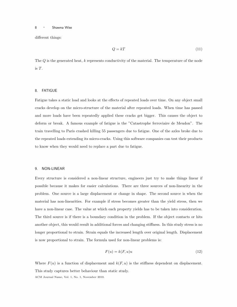
Once the type of study is chosen it is essential to pick the dimensions and material of the rod.
For this example let the length of the rod be 100 inches and let the width and length both be equal
to 1 inch. The area of the cross section needs to be calculated by using the formula A = lw = 1in x
ACM Journal Name, Vol. 1, No. 1, November 2010.
10 · Shawna Wise
1in= 1in2. The type of material selected is steel alloy.
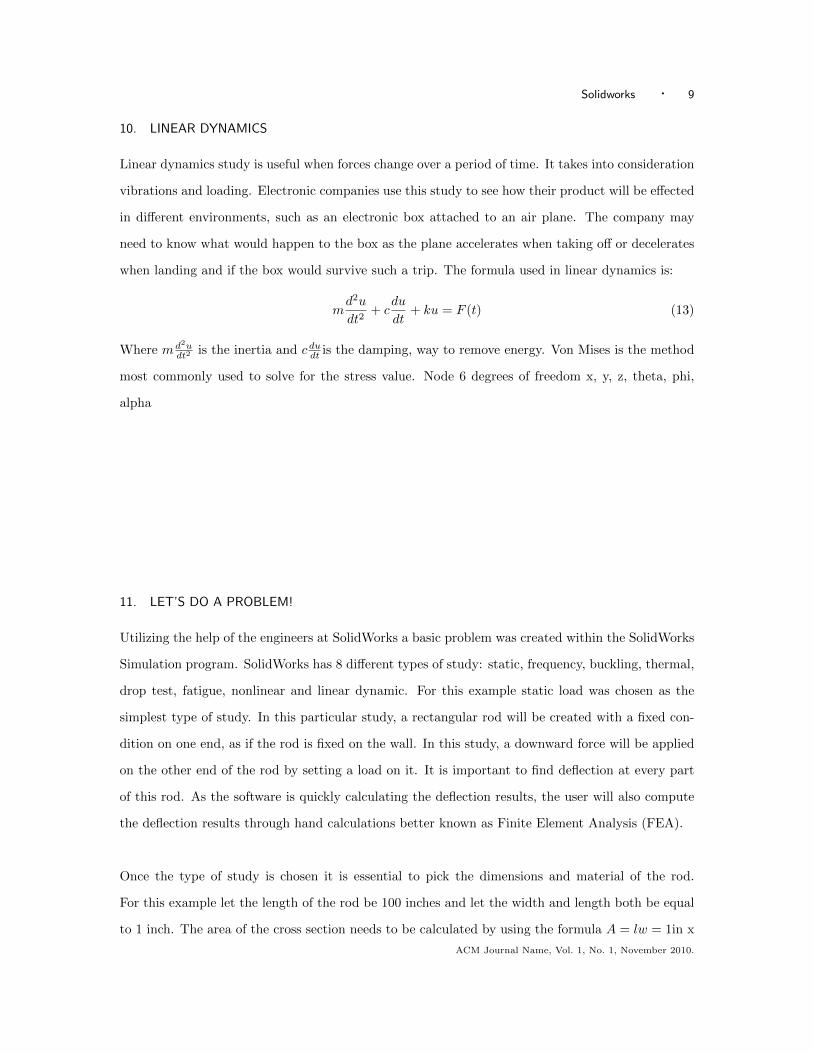
Now fix the left end; for example to a wall. Now apply a vertical force to the right end going
downward. Then create the force to be a load of 10lbs.
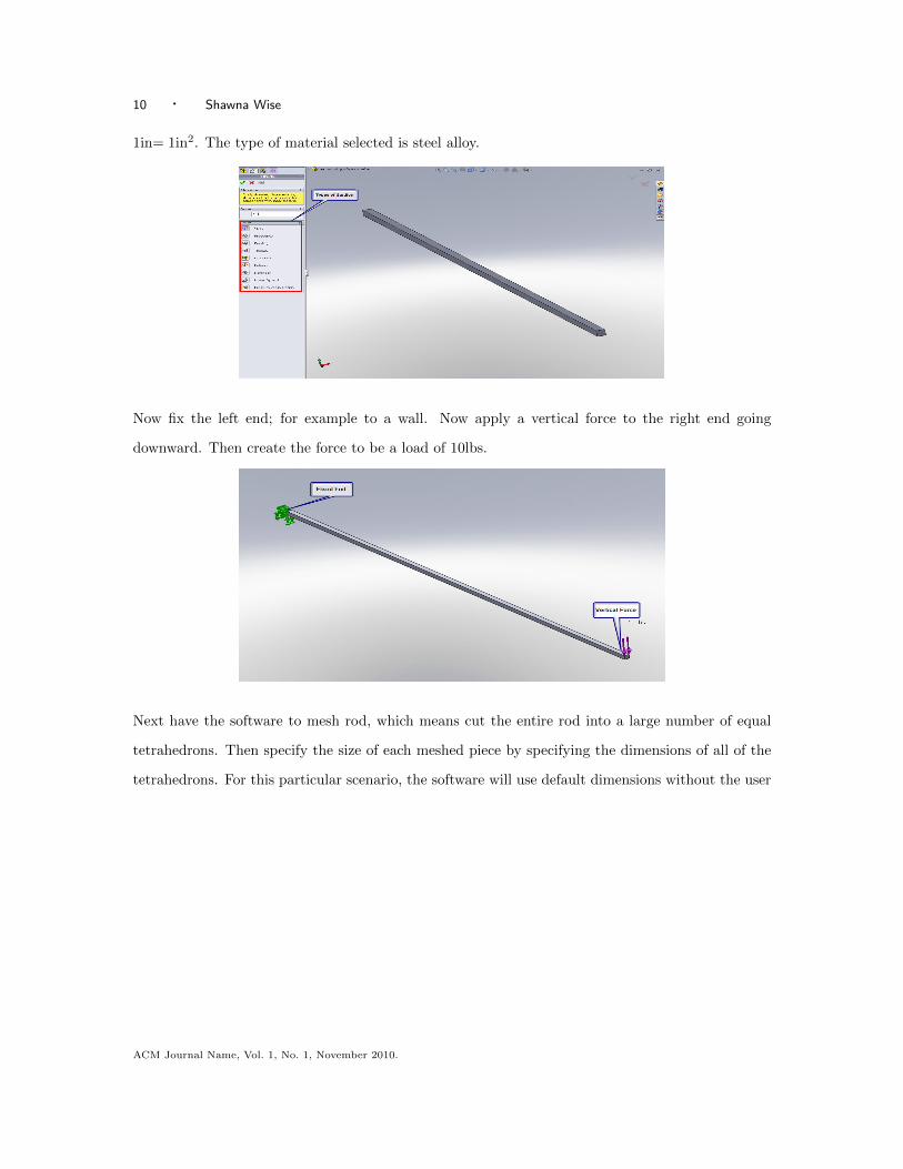
Next have the software to mesh rod, which means cut the entire rod into a large number of equal
tetrahedrons. Then specify the size of each meshed piece by specifying the dimensions of all of the
tetrahedrons. For this particular scenario, the software will use default dimensions without the user
ACM Journal Name, Vol. 1, No. 1, November 2010.
Solidworks · 11
imputing specifics.
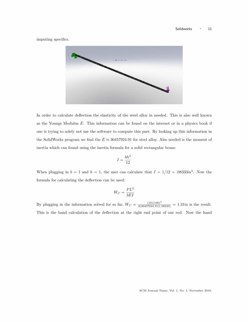
In order to calculate deflection the elasticity of the steel alloy in needed. This is also well known
as the Youngs Modulus E. This information can be found on the internet or in a physics book if
one is trying to solely not use the software to compute this part. By looking up this information in
the SolidWorks program we find the E ≈ 30457924.91 for steel alloy. Also needed is the moment of
inertia which can found using the inertia formula for a solid rectangular beam:
I =bh3
12
When plugging in b = 1 and h = 1, the user can calculate that I = 1/12 = .08333in4. Now the
formula for calculating the deflection can be used:
WC =PL3
3EI
By plugging in the information solved for so far, WC = (10)(100)3
3(30457924.91)(.08333) = 1.31in is the result.
This is the hand calculation of the deflection at the right end point of our rod. Now the hand
ACM Journal Name, Vol. 1, No. 1, November 2010.

12 · Shawna Wise
calculation of deflection and the software’s deflection calculation can be compared.
The box on the right tells the user that the displacement the software calculated is 1.3in. The calcu-
lations match! In this picture the program shows the displacement of all the partitioned tetrahedrons
across the entire rod. The red area shows the least amount of displacement; while the dark blue
area shows the most deflection. The scale goes from least to greatest deflection in this order: red,
orange, yellow, green and blue. On the left of the picture below, the material definition, boundary
condition, applied force and results for our simulation can be seen.
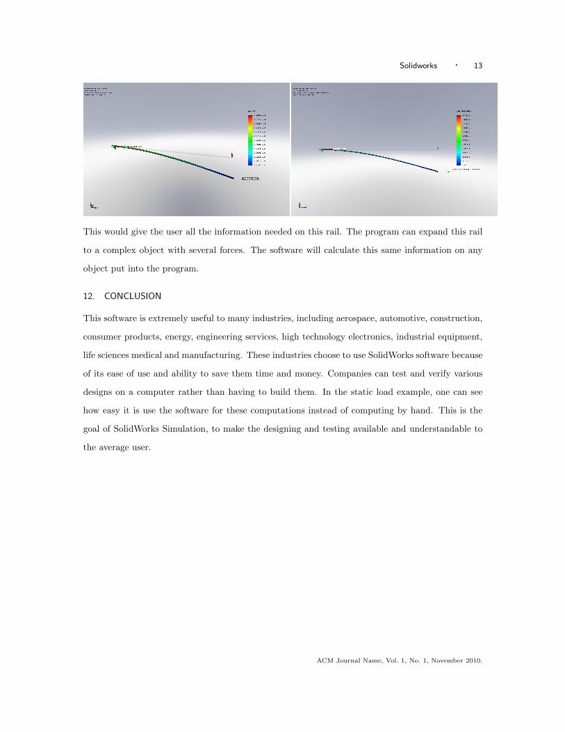
The program has also produced calculations such as ESTRN, the equivalent strain values, and the
Von Mises, the stress values, across the whole rail. The view of the rail can be changed to see the
ESTRN in relation to the rail (picture on left). There is also a window for viewing the Von Mises
in relation to the rail (picture on the right).
ACM Journal Name, Vol. 1, No. 1, November 2010.
Solidworks · 13
This would give the user all the information needed on this rail. The program can expand this rail
to a complex object with several forces. The software will calculate this same information on any
object put into the program.
12. CONCLUSION
This software is extremely useful to many industries, including aerospace, automotive, construction,
consumer products, energy, engineering services, high technology electronics, industrial equipment,
life sciences medical and manufacturing. These industries choose to use SolidWorks software because
of its ease of use and ability to save them time and money. Companies can test and verify various
designs on a computer rather than having to build them. In the static load example, one can see
how easy it is use the software for these computations instead of computing by hand. This is the
goal of SolidWorks Simulation, to make the designing and testing available and understandable to
the average user.
ACM Journal Name, Vol. 1, No. 1, November 2010.

14 · Shawna Wise
13. BIBLIOGRAPHY
Deo, Sanjay, Personal Communication, 4 November 2010
Derov, Matthew, Personal Communication, 11 November 2010
Novak, Jindrich, Personal Communication, 4 November 2010
Ranjan, Srikant, Personal Communication, 4 November 2010
ACM Journal Name, Vol. 1, No. 1, November 2010.