solidworks cad basics and stress analysis - … · an approved continuing education provider...
TRANSCRIPT

An Approved Continuing Education Provider
PDHonline Course M418 (6 PDH)
SolidWorks CAD Basics
and Stress Analysis
John Andrew, P.E.
2014
PDH Online | PDH Center
5272 Meadow Estates Drive
Fairfax, VA 22030-6658 Phone & Fax: 703-988-0088
www.PDHonline.org
www.PDHcenter.com

www.PDHcenter.com PDHonline Course M418 www.PDHonline.org
©2012 John R. Andrew Page 2 of 89
SolidWorks Parts, Assemblies, and Drawings This course can be completed without SolidWorks CAD software.
SolidWorks Car Assembly, solidsmack.com Subassembly, f1technical.net
A SolidWorks CAD model consists of 3D solid geometry in a part or assembly document.
SolidWorks Factory Assembly, designworldonline.com

www.PDHcenter.com PDHonline Course M418 www.PDHonline.org
©2012 John R. Andrew Page 3 of 89
SolidWorks includes Finite Element Analysis (FEA) Inch pound and ISO example shown above.
SolidWorks Sheet Metal formed shape. gabijack.com
Sheet Metal unfold.

www.PDHcenter.com PDHonline Course M418 www.PDHonline.org
©2012 John R. Andrew Page 4 of 89
SolidWorks Assembly Drawing with Bill of Materials
valleytoolworks.com
Insert a part or assembly into a standard ANSI or ISO drawing sheet and create isometric and
orthographic two dimensional views, sections, and details fully dimensioned automatically.
A SolidWorks assembly drawing is shown above. Drawings or assemblies can be created at any
time in the design process.
The bill of materials in the top right corner is created automatically from the 3 dimensional
assembly model. An “Exploded View” is shown on the left. The balloon part numbers are added
by SolidWorks.
Drawings are created from part and assembly models in drafting views in a drawing document as
shown above. Part numbers in balloons are created automatically.
Any dimension can be revised in any part on the drawing and the part model will “Rebuild” to
match. Click on the Rebuild icon to activate the dimension changes.
Associativity between parts, assemblies, and drawings assures that changes made to one
document or view are automatically made to all other documents and views.

www.PDHcenter.com PDHonline Course M418 www.PDHonline.org
©2012 John R. Andrew Page 5 of 89
DISCLAIMER: The materials contained in the online course are not intended as a representation or
warranty on the part of PDH Center or any other person/organization named herein. The materials
are for general information only. They are not a substitute for competent professional advice.
Application of this information to a specific project should be reviewed by a registered architect
and/or professional engineer/surveyor. Anyone making use of the information set forth herein
does so at their risk and assumes any and all resulting liability arising therefrom.
CONTENTS
1- START A NEW PART METHOD
2 - FIRST PRACTICE PART – RECTANGULAR PROFILE
3 - SECOND PRACTICE PART - ROUND REVOLVED SHAPE
4 - CREATE A CIRCULAR PATTERN OF HOLES
5 - THIRD PARACTICE PART - SWEEP
6 - CONCENTRIC PIPE REDUCER – LOFT
7 - BOTTOM UP ASSEMBLIES
8 - TOP DOWN ASSEMBLIES
9 - EXTRUDE DIRECTIONS 1 & 2
10 - REFERANCE PLANE
11 - FIRST ASSEMBLY - PIPE ELBOW
12 - SECOND ASSEMBLY - PIPE ROUTING
13 - CREATE AN ASSEMBLY DRAWING
14 - BILL OF MATERIALS
15 - REVISE DIMENSIONS WITH REBUILD
16 - 3D SKETCH AND SWEEP
17 - SHEET METAL BASICS
18 - FINITE ELEMENT ANALYSIS (FEA)
19 - SOLIDWORKS MENUS
1- START A NEW PART METHOD Open SolidWorks and start a new: Part, Assembly, or Drawing.
1 Click on the drop down menu, “Insert” > News:
Or Click on the “New” icon above left > and the “New SolidWorks Document” below will open.

www.PDHcenter.com PDHonline Course M418 www.PDHonline.org
©2012 John R. Andrew Page 6 of 89
“New SolidWorks Document” dialog box with choices: Part, Assembly, or Drawing.
3
The above window will open next.
A two dimensional sketch needs to be created on the selected plane: Front, Right, or Top.

www.PDHcenter.com PDHonline Course M418 www.PDHonline.org
©2012 John R. Andrew Page 7 of 89
A two dimensional sketch must be created on a selected plane or surface before the desired solid
model can be created.
Pick the “Right” Plane > Sketch a base feature and centerline shown above left.
Click the “Smart Dimension” icon and add dimensions > Exit Sketch.
Form a 3 dimensional “Revolved solid model” shown above right.
Left, click the “Sketch” tab shown above to obtain the sketch tools.
Other solid models include the extruded boss with holes added above.
Lofted eccentric pipe reducer solid model. A 3D dimensioned sketch is the basis of this part.
Lofted parts have multiple cross sections and a path.

www.PDHcenter.com PDHonline Course M418 www.PDHonline.org
©2012 John R. Andrew Page 8 of 89
Swept solid models Click the “Features” tab shown above to obtain other tools.
Click the “Display Mode” icon to obtain the part or assembly modes above.
Left geometric “Relations” between lines in a sketch may be inserted manually. Right geometric “Relations” between parts in an assembly may be inserted manually.

www.PDHcenter.com PDHonline Course M418 www.PDHonline.org
©2012 John R. Andrew Page 9 of 89
WEB LINKS SolidWorks web site: www.solidworks.com 3D ContentCentral online at: (http://www.3dcontentcentral.com/default.aspx) is a free source of
SolidWorks part and assembly models.
SoldWorks in Ten Minutes video: http://www.youtube.com/watch?v=pFy8iijJSHM&feature=related
Getting Started with SoldWorks video:
http://www.youtube.com/watch?v=cmC2MLRetko&feature=related
Large Assembly layout and motion http://www.youtube.com/watch?v=uMnd69-
aueM&feature=related
SolidWorks - Assembly Layout and Motion
File > New > Assembly > Create Assembly > Sketch > Blocks
http://www.youtube.com/watch?v=BFzuDaMfGrE&feature=related
3D ContentCentral® is a
free service for locating,
configuring, downloading,
and requesting 2D and 3D
parts and assemblies, 2D
blocks, library features,
and macros.
Join an active community
of 903,735 CAD users who
share and download user
contributed and supplier-
certified 2D and 3D parts
& assemblies, 2D blocks,
library features and
macros.
www.PDHcenter.com PDHonline Course M418 www.PDHonline.org
©2012 John R. Andrew Page 10 of 89
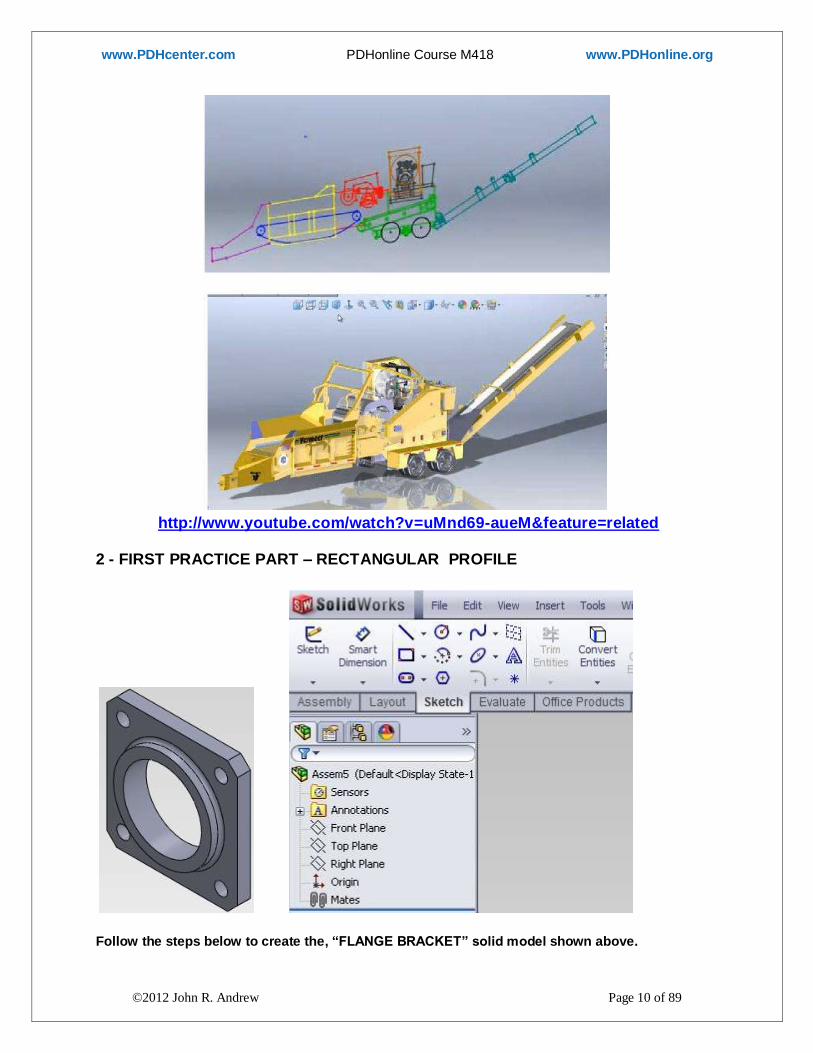
http://www.youtube.com/watch?v=uMnd69-aueM&feature=related
2 - FIRST PRACTICE PART – RECTANGULAR PROFILE
Follow the steps below to create the, “FLANGE BRACKET” solid model shown above.

www.PDHcenter.com PDHonline Course M418 www.PDHonline.org
©2012 John R. Andrew Page 11 of 89
Start the 3 Dimensional Model by clicking on the “New” icon or pick drop down menu: Insert >
New.
Click left mouse button: New > Part > OK. The “Feature Tree” below will now open.
A two dimensional sketch must be created on a selected plane or surface before the desired solid
model can be created.
Click the, “Features” tab to obtain the “Feature Tree” > Click “Front Plane”
Make a profile sketch on the selected Front Plane as shown below.

www.PDHcenter.com PDHonline Course M418 www.PDHonline.org
©2012 John R. Andrew Page 12 of 89
Open the “Document Properties” box shown above to change units of measurement.
Pick drop down menu: Tools > Option > Document Properties > Units > IPS (inch, pound,
second). MMGS (millimeter, gram, second) is also available.
The Origin, x, and y directions are shown in the chosen front plane.

www.PDHcenter.com PDHonline Course M418 www.PDHonline.org
©2012 John R. Andrew Page 13 of 89
Pick: “Sketch” tab > Pick the “Rectangle” tool >
Right click the “Origin” > Drag mouse pointer to a temporary top right corner > Click.
Click the green check mark (OK) to complete the rectangle command.
Horizontal, Vertical and other geometric relations between lines are added automatically by
SolidWorks.
Or manually using drop down menu: Insert > Relations.
Pick “Smart Dimension” tool > Pick the left side of the rectangle >
Drag dimension away from the rectangle and pick to place the dimension as above.
Modify the dimension > type 5 > Click check mark to complete the command.

www.PDHcenter.com PDHonline Course M418 www.PDHonline.org
©2012 John R. Andrew Page 14 of 89
Dimension a side normal to the first dimension.
Modify the dimension > type 5 > Click check mark to complete (OK). Click “Exit Sketch”.
Pick the “Isometric View” icon in the “Views” toolbar above.
TYPE f to fit the object in the display
Pick “Extruded Boss/Base” > Blind > D1 thickness > Type D1 dimension > 0.50in >

www.PDHcenter.com PDHonline Course M418 www.PDHonline.org
©2012 John R. Andrew Page 15 of 89
Click the above green check mark (OK) to complete the extrude boss command.
Note: The “Boss/Extrude” dialog box allows extrusion in both directions perpendicular to the
profile sketch plane. See “Direction 1” and “Direction 2” above and in section 10 - First Assembly
- Pipe Elbow below.
Model the two holes above.
Pick the front surface of the part above > Select the “Features” tab > Pick “Extruded Cut”.
Pick” Sketch tab > Circle tool > Sketch the 2 holes shown above > Smart Dimension tool > add
0.500 inch diameter and the above hole location dimensions > Click: Exit Sketch.

www.PDHcenter.com PDHonline Course M418 www.PDHonline.org
©2012 John R. Andrew Page 16 of 89
REFERENCE PLANES
Insert > Reference Geometry > Plane > Pick the right side surface >
Rotate the part by holding the mouse wheel down and drag horizontally across the part > Pick the
left side surface > the above “Mid-Plane” is created by SolidWorks.
Insert > Pattern/Mirror > Pick the two left holes to mirror > the two holes on the right side are
created below.
Cut-Extrude > Sketch the large center hole on the front surface of the part > Click Smart
Dimension > Dimension the center hole 3.00 inch diameter and add the hole location dimensions >
Exit Sketch.
Insert > Cut > Extrude > Thru all > Click check mark.
Insert > Features > Chamfer > Pick each of the 4 corners > OK
Or click the “Fillet” icon drop down menu > Chamfer > Pick each of the 4 corners > OK

www.PDHcenter.com PDHonline Course M418 www.PDHonline.org
©2012 John R. Andrew Page 17 of 89
The “Features Tree” above lists all operations performed on the part (or assembly) model.
Double-click on an icon to modify that feature in the part.
Pick the front surface > Sketch > Circle tool > Smart Dimension > 3.00 diameter >
Tools > Sketch Tools > Convert entities > Click on edge of the 2.75 inch diameter circle > Click the
green check > Exit Sketch.
Insert Boss/Base > Extrude > Pick the ring > Click the green check.
Click ring base > “Fillet” icon or Insert > Features > Fillet/Round

www.PDHcenter.com PDHonline Course M418 www.PDHonline.org
©2012 John R. Andrew Page 18 of 89
Click “Isometric View” in the “Orientation” dialog box above.
Save As > BASE PLATE > “.SLDPRT” is added by SolidWorks.

www.PDHcenter.com PDHonline Course M418 www.PDHonline.org
©2012 John R. Andrew Page 19 of 89
PARAMETRIC CAD The rectangular plate solid model with five holes has been fully dimensioned and saved.
It is possible to re-open this part in SolidWorks, double click on its surface, and change one or all
of its dimensions.
SolidWorks software utilizes a design feature called parametric computer aided design, a method
of linking dimensions and variables to geometry in such a way that when the values change, the
part changes as well.
A parameter is a variable to which other variables are related, and these other variables can be
obtained by means of parametric equations.
In this manner, design modifications and creation of a family of parts can be performed in
remarkably quick time compared with the redrawing required by traditional CAD.
In the past five years, PTC's success has prompted major CAD players to offer similar functions.
Parametric modification can be accomplished with a spreadsheet, script, or by manually changing
dimension text in the digital model.
3 - SECOND PRACTICE PART - ROUND REVOLVED SHAPE

www.PDHcenter.com PDHonline Course M418 www.PDHonline.org
©2012 John R. Andrew Page 20 of 89
Follow the steps below to create the above “FLANGE” revolved shape solid model.
Start the 3 Dimensional Model by clicking on the “New” icon > OK
Right click > “Right Plane” under the “Features” tab shown above.
Origin and x and y directions are shown in the Right Plane.
“Sketch” tab > Pick the “Line” tool shown above.
Sketch the shape shown above with the line tool by following the steps below.

www.PDHcenter.com PDHonline Course M418 www.PDHonline.org
©2012 John R. Andrew Page 21 of 89
Right click on the “Origin” point > Drag mouse pointer to right bottom corner 1 > Release mouse
button > Click on 1 and drag to 2 > 3 > 4 > 5 > 6 > 7 > Origin to complete the “Profile”.
Click the “Line” tool drop down menu > Pick the “Center Line” icon > Sketch the center line AB
above > Pick the “Exit Sketch” icon > OK.
When creating a “Revolved Boss/Base” from a sketched profile there must be an axis to revolve
the profile around.
Pick “Smart Dimension” tool > add the dimensions shown below.
Click to complete dimensioning.
TYPE f to fit the above sketch, part, or assembly in the display area
Add the dimensions shown above with the “Smart Dimension” tool.
Pick the “Isometric View” icon shown highlighted above.

www.PDHcenter.com PDHonline Course M418 www.PDHonline.org
©2012 John R. Andrew Page 22 of 89
The isometric view above > Pick “(-)Sketch1) above > Pick “Axis of Revolution” above > 360 deg >
Pick” Green arrow (OK).
Pick Sketch1 > Insert > Boss/Base > Revolve > OK
REVOLVED PROFILE
Revolved profile is shown above.
4 – CREATE A CIRCULAR PATTERN OF HOLES A first hole must be created in a part before a circular pattern of identical holes can be made.

www.PDHcenter.com PDHonline Course M418 www.PDHonline.org
©2012 John R. Andrew Page 23 of 89
To obtain a part sectioned view pick an existing plane in the Features Tree > “Right Plane” or
create a plane relative to an existing plane or surface by clicking: Insert >Reference Geometry >
Plane > Pick an existing plane > Create a new plane at the desired section location > OK > Pick the
“Section” icon below.
Click “Right Plane” in the Features Tree > Click the “Section” tool icon > Click the “Reverse
View”.
1 Click Isometric icon, then click Shaded view mode.
2 Click Right Plane in the Feature Manager design tree.
3 Click Section View on the View toolbar, or click View, Display, Section View.

www.PDHcenter.com PDHonline Course M418 www.PDHonline.org
©2012 John R. Andrew Page 24 of 89
Pick the flange front surface > Sketch >
Pick: “Line” drop down menu > Pick: “Center line” icon > Pick flange center hole center point >
Drag up > Pick top end point of this centerline > Existing Relations above are > Vertical &
Coicident1 > Add Relations > Vertical > OK.
“Cut” the first bolt hole.
Pick: “Smart Dimension” icon > Dimension the hole 7/8 inch diameter and 4.750 radius > Exit
Sketch.
Pick the bolt diameter circle > Insert > Cut > Extrude > OK
www.PDHcenter.com PDHonline Course M418 www.PDHonline.org
©2012 John R. Andrew Page 25 of 89
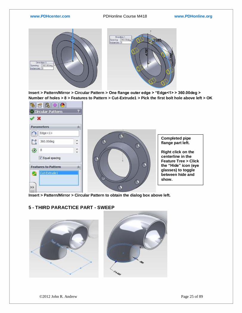
Insert > Pattern/Mirror > Circular Pattern > One flange outer edge > “Edge<1> > 360.00deg >
Number of holes > 8 > Features to Pattern > Cut-Extrude1 > Pick the first bolt hole above left > OK
Insert > Pattern/Mirror > Circular Pattern to obtain the dialog box above left.
5 - THIRD PARACTICE PART - SWEEP
Completed pipe flange part left. Right click on the centerline in the Feature Tree > Click the “Hide” icon (eye glasses) to toggle between hide and
show.

www.PDHcenter.com PDHonline Course M418 www.PDHonline.org
©2012 John R. Andrew Page 26 of 89
Pipe elbow part is shown above. Pick: Top Plane > Sketch > Circle tool > Pipe inside outside
diameter > (Create the pipe inside diameter) > Offset Entities >.280in > Exit Sketch.
Pick: Front Plane > Sketch the 9.000 inch radius 90 degree arch with > 3-Point Circle > Exit
Sketch. Sweep Boss/Base icon > Pick Sketch1 > Pick Sketch2, in the Features Tree > OK.
6 - CONCENTRIC PIPE REDUCER – LOFT 24
New > Part > OK >
3D Sketch > 3.000 Line > 5.500 Line > 3.000 Line > OK
www.PDHcenter.com PDHonline Course M418 www.PDHonline.org
©2012 John R. Andrew Page 27 of 89
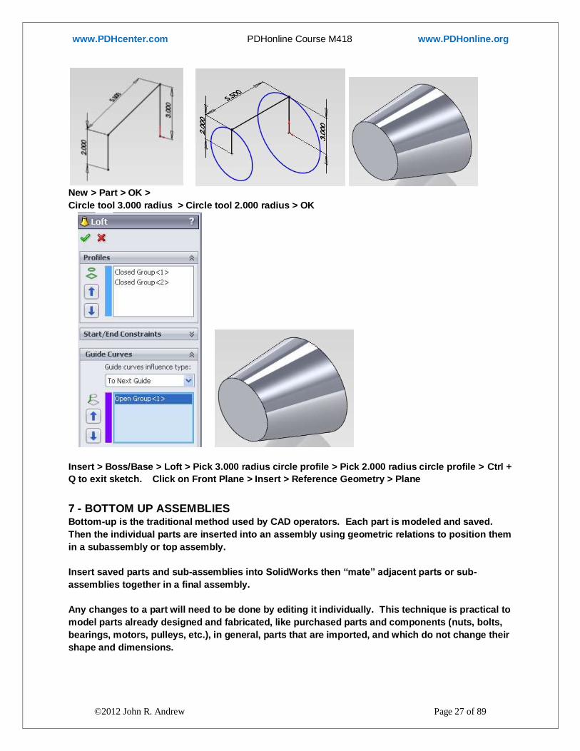
New > Part > OK >
Circle tool 3.000 radius > Circle tool 2.000 radius > OK
Insert > Boss/Base > Loft > Pick 3.000 radius circle profile > Pick 2.000 radius circle profile > Ctrl +
Q to exit sketch. Click on Front Plane > Insert > Reference Geometry > Plane
7 - BOTTOM UP ASSEMBLIES Bottom-up is the traditional method used by CAD operators. Each part is modeled and saved.
Then the individual parts are inserted into an assembly using geometric relations to position them
in a subassembly or top assembly.
Insert saved parts and sub-assemblies into SolidWorks then “mate” adjacent parts or sub-
assemblies together in a final assembly.
Any changes to a part will need to be done by editing it individually. This technique is practical to
model parts already designed and fabricated, like purchased parts and components (nuts, bolts,
bearings, motors, pulleys, etc.), in general, parts that are imported, and which do not change their
shape and dimensions.

www.PDHcenter.com PDHonline Course M418 www.PDHonline.org
©2012 John R. Andrew Page 28 of 89
8 - TOP DOWN ASSEMBLIES Top-down assemblies where created from parts modeled "inside" the assembly, being related to
"driving" entities inside the assembly which control the shape, features, dimensions and position
of those parts, in a way that changes introduced to the "driving" entities "drive" the configuration
of all the "in-context" modeled parts and therefore the entire assembly.
Top-down modeling makes possible the creation of parametric assemblies systems, which cannot
be done using the Bottom-up technique alone.
Creating a properly structured Top-down assembly requires more analysis and work that the
creation of a Bottom-up model, however, the advantage of top-down modeling for people doing
product design is that very little work (and time) will be required when design changes occur,
since all parts and components will automatically update to new shapes, dimensions, position,
etc. as new input parameters are entered into the "driving" entities at the assembly level.
9 – EXTRUDE DIRECTIONS 1 & 2
New > Part > OK > Pick Front Plane > Sketch > Circle tool > 6.000 inch diameter circle > OK
Note the “Offset Entities” tool to be used below.

www.PDHcenter.com PDHonline Course M418 www.PDHonline.org
©2012 John R. Andrew Page 29 of 89
The pipe outside diameter is 6.000 inches.
The pipe wall thickness is 0.375 inches.
Pick “Offset Entities” tool > .375 > OK
The concentric circles sketch is named Sketch2 and added to the “Feature Tree” below
The “Boss/Extrude” dialog box allows extrusion in both directions perpendicular to the profile
sketch plane.
Extrude Sketch2 6.000 inches right to left and 8.000 inches left to right from the Front Plane.
Pick Sketch2 in the Feature Tree shown above > Boss Extrude > Front Plane > D1 > 6.00in > D2 >
8.00in > OK.

www.PDHcenter.com PDHonline Course M418 www.PDHonline.org
©2012 John R. Andrew Page 30 of 89
The pipe extruded in two directions is shown above.
Pick the front plane in the Features Tree > Sketch > Pick the line drop-down menu > Center Line
Pick the Origin and drag right to create the horizontal line above > Exit Sketch.

www.PDHcenter.com PDHonline Course M418 www.PDHonline.org
©2012 John R. Andrew Page 31 of 89
10 - REFERANCE PLANE
Pick the front plane > Insert Reference Geometry > Plane
First Reference > Front Plane
Second Reference > Centerline (Line1@Sketch2) > Angle > 45.00 deg > OK
Sketch the concentric circles on plane1 by the method described above.

www.PDHcenter.com PDHonline Course M418 www.PDHonline.org
©2012 John R. Andrew Page 32 of 89
Boss-Extrude > Blind > 9.00in > OK.
Edit front 6.00 inch dimension > 9.00 inch

www.PDHcenter.com PDHonline Course M418 www.PDHonline.org
©2012 John R. Andrew Page 33 of 89
Click the “Rebuild” tool to stretch the pipe.
Completed “Lateral”
11 - FIRST ASSEMBLY - PIPE ELBOW Begin the assembly by opening two existing parts “Elbow and pipe 1” in SolidWorks.

www.PDHcenter.com PDHonline Course M418 www.PDHonline.org
©2012 John R. Andrew Page 34 of 89
Pick: Start > Assembly > OK.
The “Elbow” and “pipe 1” parts above have been created by the methods described.

www.PDHcenter.com PDHonline Course M418 www.PDHonline.org
©2012 John R. Andrew Page 35 of 89
These two existing parts have been previously opened in SolidWorks, “Elbow and pipe 1” and
appear automatically in the above “Insert Component” dialog box.
If the “Elbow and pipe 1” parts had not been opened, click Browse, locate the file containing the
parts, and insert them.
Drag one part at a time into the assembly area shown right above.
The first part dragged into the assembly area will be “anchored” and not able to be moved or
rotated.
Insert component > Existing Part > pipe 1.
This is the first component of the assembly and it is anchored. It cannot be moved or rotated.
Pick the “Mate” paper clip icon on the Assembly tab > Pick outer edge of Pipe end > Pick outer
edge of Elbow end > OK

www.PDHcenter.com PDHonline Course M418 www.PDHonline.org
©2012 John R. Andrew Page 36 of 89
Rotate the Elbow 180 degrees relative to the fixed pipe 1 by the method below.
Pick pipe “Right Plane” > Hold “Ctrl” key > Pick elbow “Front Plane” > Mate >

www.PDHcenter.com PDHonline Course M418 www.PDHonline.org
©2012 John R. Andrew Page 37 of 89
Type “180” deg > Green Check > OK. The Standard Mates dialog box above will open or:
Pick drop down menu: Insert > Mate > Pick pipe “Right Plane” > Hold “Ctrl” key > Pick elbow
“Front Plane” > Type “180” deg > Green Check > OK.
Completed Pipe Sub-Assembly Geometric “Relations” between parts.

www.PDHcenter.com PDHonline Course M418 www.PDHonline.org
©2012 John R. Andrew Page 38 of 89
12 - SECOND ASSEMBLY - PIPE RUN
“SOLIDWORKS PREMIUM” has “Pipe Routing” add-in items above and below. YouTube https://www.youtube.com/watch?v=uSST3W0_Ojs
Design Library > Equipment > Tanks > Pumps > Fittings > Valves > etc.
New > Assembly. Tools > Add-Ins > Routing > (Electrical, Piping & Tubing)
Drag Tanks, Pumps or other into the assembly area.
1. DRAG & DROP onto Equipment Equipment > Pick a Flange > Drag this flange onto a point on a Tank or other equipment item.

www.PDHcenter.com PDHonline Course M418 www.PDHonline.org
©2012 John R. Andrew Page 39 of 89
2. DRAG & DROP onto 3D Sketch Start Point Pick a Flange > Drag this flange onto the 3D Sketch Start Point
Select a flange and place it at the pipe starting point > “TAB” key to orient. Accept the standard configuration in the menu on the left side of the screen.
Create lines in the 3D Sketch area. SolidWorks adds the pipe run. “TAB” key to orient.
Select the Standard 4 inch 300 lb per
square inch pressure pipe flange.
SolidWorks creates a short
stub pipe in the slip-on type
flange.

www.PDHcenter.com PDHonline Course M418 www.PDHonline.org
©2012 John R. Andrew Page 40 of 89
Use SolidWorks “ Extrude” to create straight sections of pipe and
“Pipe” “Routing” for elbows, tees, valves, and flanges.
Open “Design Library”

www.PDHcenter.com PDHonline Course M418 www.PDHonline.org
©2012 John R. Andrew Page 41 of 89
Create straight pipe sections and insert elbows, tees, reducers, pumps and
valves from the SolidWorks Design Library.
Pipe run assembly example is shown above.
Note the list of nine parts above right that have been previously created by the methods described
in this course above.
Open the nine piping items in the list above or Browse for each part one at a time by:
Insert > Component > Existing Part/Assembly > Browse > Flange >
www.PDHcenter.com PDHonline Course M418 www.PDHonline.org
©2012 John R. Andrew Page 42 of 89
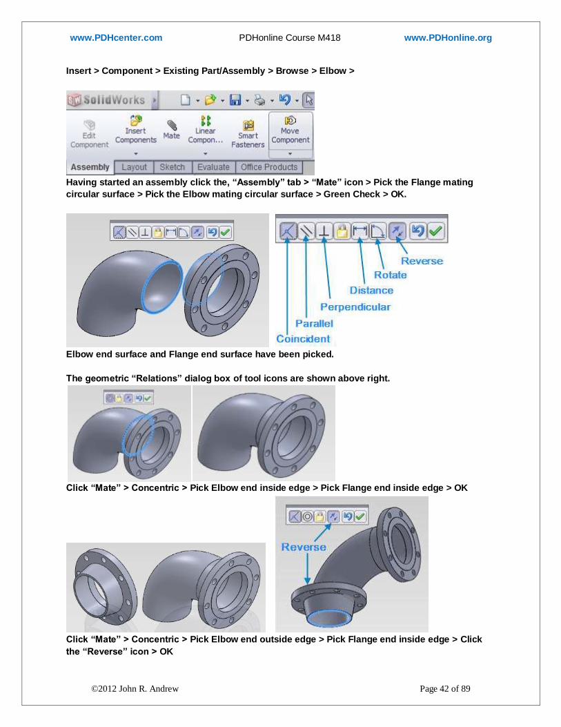
Insert > Component > Existing Part/Assembly > Browse > Elbow >
Having started an assembly click the, “Assembly” tab > “Mate” icon > Pick the Flange mating
circular surface > Pick the Elbow mating circular surface > Green Check > OK.
Elbow end surface and Flange end surface have been picked.
The geometric “Relations” dialog box of tool icons are shown above right.
Click “Mate” > Concentric > Pick Elbow end inside edge > Pick Flange end inside edge > OK
Click “Mate” > Concentric > Pick Elbow end outside edge > Pick Flange end inside edge > Click
the “Reverse” icon > OK

www.PDHcenter.com PDHonline Course M418 www.PDHonline.org
©2012 John R. Andrew Page 43 of 89
Insert > Mirror Components > Pick Mirror Plane > Pick flange face > Component to Mirror > Pick
the top right flange > OK > Rebuild.
Click the “Mate” icon > Pick the Flange mating circular surface > Pick the Pipe mating circular
surface > Green Check > OK.
Click “Mate” > Concentric > Pick Pipe end inside edge > Pick Flange end inside edge > OK

www.PDHcenter.com PDHonline Course M418 www.PDHonline.org
©2012 John R. Andrew Page 44 of 89
Insert > Reference Geometry > Axis
Insert > Reference Geometry > Plane

www.PDHcenter.com PDHonline Course M418 www.PDHonline.org
©2012 John R. Andrew Page 45 of 89
“Insert > Mate” as described above repeatedly to complete the pipe assembly.

www.PDHcenter.com PDHonline Course M418 www.PDHonline.org
©2012 John R. Andrew Page 46 of 89
13 - CREATE AN ASSEMBLY DRAWING

www.PDHcenter.com PDHonline Course M418 www.PDHonline.org
©2012 John R. Andrew Page 47 of 89
Completed pipe assembly drawing with bill of materials in an ANSI A size drawing template.
Open the assembly to be inserted into a 2D drawing.

www.PDHcenter.com PDHonline Course M418 www.PDHonline.org
©2012 John R. Andrew Page 48 of 89
File > Open > Browse for the folder containing an assembly or part to place in a two dimensional
drawing.
The desired assembly is now open in SolidWorks.
File > New > Drawing > OK >
To open an “A” size drawing template, click drop down menu:
File > New > Drawing > OK > A (ANSI) Landscape > OK.

www.PDHcenter.com PDHonline Course M418 www.PDHonline.org
©2012 John R. Andrew Page 49 of 89
A blank standard ANSI A size template has been opened. Other template sizes are available.
A custom template can be created by modifying one of the standard templates and saving it.

www.PDHcenter.com PDHonline Course M418 www.PDHonline.org
©2012 John R. Andrew Page 50 of 89
Insert > Drawing View > Model Click the: Model View tab > Model View icon >
Check “Create multiple views” > Pick desired views > Green check mark >
View boxes appear in the drawing above after the above commands are made.

www.PDHcenter.com PDHonline Course M418 www.PDHonline.org
©2012 John R. Andrew Page 51 of 89
The Isometric view is not usually dimensioned so choose “No”.
The 1st Angle views above inserted by the software need to be changed to 3rd angle.
1st angle views have been changed to 3rd angle views
Click on a view > pick an edge of the view box > drag view to a new location.

www.PDHcenter.com PDHonline Course M418 www.PDHonline.org
©2012 John R. Andrew Page 52 of 89
Right click on “Sheet Format1” > pick Sheet Properties > click Third Angle in Type of projection.
Right click on “Sheet Format1” to edit the title block.
Open System Options by right clicking on a view in the drawing.
Click on “Display Style” > Hidden lines removed.

www.PDHcenter.com PDHonline Course M418 www.PDHonline.org
©2012 John R. Andrew Page 53 of 89
Initial title block to be updated.
Double click on item to be edited.
Drawing title, “Assignment 2-8” has been changed to “Pump Piping”.
Right click on “Sheet Format” to exit edit.

www.PDHcenter.com PDHonline Course M418 www.PDHonline.org
©2012 John R. Andrew Page 54 of 89
Right click on the bottom right view in the drawing > The “Drawing View2” dialog box will open.
Click “Use custom scale” > Select User Defined > Change the scale from 1:48 to 1:32.
Pick the top left view and change its scale also.

www.PDHcenter.com PDHonline Course M418 www.PDHonline.org
©2012 John R. Andrew Page 55 of 89
The new scale is 1:32 for the Isometric and three 2D views.
Tools > Options > Document Properties > ANSI
Next, click “Units” and select US or Metric.

www.PDHcenter.com PDHonline Course M418 www.PDHonline.org
©2012 John R. Andrew Page 56 of 89
ADD DIMENSIONS TO DRAWING VIEWS – METHOD-1
Pick the “Line” icon drop down menu triangle > Pick “Center Line” > Pick the approximate center
of a pipe and it will snap to the exact center > drag the center line horizontally or vertically to
increase its length.
Pick the “Smart Dimension” icon and add the dimensions shown above.
Add all necessary dimensions to each view.

www.PDHcenter.com PDHonline Course M418 www.PDHonline.org
©2012 John R. Andrew Page 57 of 89
ADD DIMENSIONS TO DRAWING VIEWS – METHOD-2
Pick the drop down menu > “Insert” > “Model Items” to obtain the box above.
ADD DIMENSIONS TO DRAWING VIEWS – METHOD-2
Pick the drop down menu > “Insert” > “Model Items” to
obtain the box above.
Select features in a view and dimensions that were used
to create the part will be inserted by the software.
Or check the box, “Import items into all views”.
Click desired items under headings: Dimensions,
Annotations, Reference Geometry, and Options.

www.PDHcenter.com PDHonline Course M418 www.PDHonline.org
©2012 John R. Andrew Page 58 of 89
Right click the top left view > Pick the “Shaded with edges” icon highlighted upper left.
The top left view is now “shaded with edges”.

www.PDHcenter.com PDHonline Course M418 www.PDHonline.org
©2012 John R. Andrew Page 59 of 89
Make room for the Bill Of Materials, BOM.
Remove the view at bottom left.
Right click the bottom left view boarder > Delete key > OK
14 - BILL OF MATERIALS Pick drop down menu: Insert > Tables > Bill of Materials > Select the isometric or other view >
File > Print Preview > Print
Pick the top left view again > Insert > Tables > Bill of Materials > OK
Place the BOM at a convenient location with the mouse pointer.

www.PDHcenter.com PDHonline Course M418 www.PDHonline.org
©2012 John R. Andrew Page 60 of 89
The Bill of Materials has been placed at a convenient location in to the drawing.
Add part number balloons automatically. Right click on the top left view > Annotations > Auto
Balloon > Style > Box > OK. The “Balloons” are added to the drawing. Pick a balloon and drag to
move as required for readability.

www.PDHcenter.com PDHonline Course M418 www.PDHonline.org
©2012 John R. Andrew Page 61 of 89
The finished dimensioned two view drawing with Isometric view and bill of materials.
15 - REVISE DIMENSIONS WITH REBUILD Part dimensions may be edited in the drawing followed by “Rebuild” to update the part and
related assemblies.
Double-Click on dimensions to edit > Click outside the edit box to close this command.
Click on the “Rebuild” icon shown above to make the change to model dimensions. The drawing
and model dimensions will be changed.
www.PDHcenter.com PDHonline Course M418 www.PDHonline.org
©2012 John R. Andrew Page 62 of 89
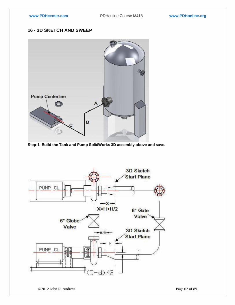
16 - 3D SKETCH AND SWEEP
Step-1 Build the Tank and Pump SolidWorks 3D assembly above and save.

www.PDHcenter.com PDHonline Course M418 www.PDHonline.org
©2012 John R. Andrew Page 63 of 89
Step-2 Add the 8”x 6” eccentric reducer with flange bolted to the pump suction flange.
New > Part > OK >
Circle tool 3.000 radius > Circle tool 2.000 radius > OK
Insert > Boss/Base > Loft > Pick 3.000 radius circle profile > Pick 2.000 radius circle profile > Ctrl +
Q to exit sketch. Click on Front Plane > Insert > Reference Geometry > Plane
6 x 4 ECCENTRIC REDUCER

www.PDHcenter.com PDHonline Course M418 www.PDHonline.org
©2012 John R. Andrew Page 64 of 89
Create a pipe run from the above tank discharge flange to pump suction flange.
Step-3 Create the dimensioned drawing above, save and print a hard copy.
4 Write values of dimensions A, B, and C on the above pump-tank picture. 5 Create a “Plane” on the 8” diameter face of the 8”x 6” eccentric reducer.

www.PDHcenter.com PDHonline Course M418 www.PDHonline.org
©2012 John R. Andrew Page 65 of 89
6 Open the 3D assembly and make a 3D Sketch pipe line from the pump suction 8”x 6” eccentric
reducer to the tank outlet.
Insert > 3D Sketch > Line tool > Pick the 8” diameter center point on the 3D Sketch start plane >
Drag to form Line C > Tab key to change direction > Draw line B > Tab key to change direction >
Draw line A terminating at the 8” diameter tank Suction Flange.
7 Insert the 6” and 8” Gate Valves.
8 Create the 8 inch diameter pipe run, Tank to Pump with the “Sweep” command.
SOLIDWORKS SWEEP – PIPE RUN
1-SWEEP 2-EDIT SKETCH

www.PDHcenter.com PDHonline Course M418 www.PDHonline.org
©2012 John R. Andrew Page 66 of 89
3-REBUILD 4-DESIGN TREE
17 - SHEET METAL BASICS
Right click on a menu > select Sheet Metal menu.

www.PDHcenter.com PDHonline Course M418 www.PDHonline.org
©2012 John R. Andrew Page 67 of 89
Select “Base Flange” > Sketch > Rectangle > Smart Dimension > 6.00 x 4.00.
When sketch is done > Pick green check mark top left or OK icon (shaded) top right.
Sheet metal “Base Part” > Pick one edge > Pull arrow up or down >

www.PDHcenter.com PDHonline Course M418 www.PDHonline.org
©2012 John R. Andrew Page 68 of 89
Enter Flange Length > 1.00 > Pick > Flange Position > Ok > Rebuild > Save-As.
Sheet Metal > Base Flange/Tab > Sketch > Rectangle on an edge > Dimension.
Sheet Metal > Base Flange/Tab > OK > Rebuild > Save. Tab is created.

www.PDHcenter.com PDHonline Course M418 www.PDHonline.org
©2012 John R. Andrew Page 69 of 89
Sheet Metal > Sketched Bend > Pick top surface > Line > Sketch line > OK > OK > Sheet Metal > Sketched Bend > Pick top face > Bend Position > Angle > 45 > OK.
Tab at 45 deg. Created.
Repeat “Sheet Metal > Sketched Bend” on tab top surface > Bend > 45 deg. > down.
Sheet Metal > Flatten > OK. Sheet Metal > Flatten again > Bent Part > OK.
New > Drawing > A-Size Landscape.

www.PDHcenter.com PDHonline Course M418 www.PDHonline.org
©2012 John R. Andrew Page 70 of 89
View Layout > Standard 3 View > Annotation > Place Dimensions
Pick > New Sheet (at bottom left) > Model View >
Double click on Sheet Metal part or Browse to find it > Check “Flat pattern”

www.PDHcenter.com PDHonline Course M418 www.PDHonline.org
©2012 John R. Andrew Page 71 of 89
Annotation > Add dimensions > Save > OK.
18 - FINITE ELEMENT ANALYSIS (FEA)
SolidWorks CAD software includes finite element analysis applied to: stress,
deflection, fluid flow, and temperature distributions. Open SolidWorks
Follow the steps below to create the above channel bracket and perform a finite element analysis
to determine the stress distribution and deflections due to applied loads.

www.PDHcenter.com PDHonline Course M418 www.PDHonline.org
©2012 John R. Andrew Page 72 of 89
Pick the: Right Plane icon > Sketch icon >
Sketch the above channel shape
Pick > Sketch > Line tool > Pick the bottom left corner as shown above > Sketch the channel
profile one straight line at a time.
Smart dim > .375 > .500 > 2.000 > 3.000 > Exit Sketch > OK

www.PDHcenter.com PDHonline Course M418 www.PDHonline.org
©2012 John R. Andrew Page 73 of 89
Add thickness (6.00 inches) to the rectangle by extruding it.
Select the “Boss-Extrude” icon > Blind > 6.000 > OK File >Save As > CHANNEL BRACKET
Create a round “Load Zone” .750 inch diameter on the top surface of the channel.
Pick the top surface of the channel > Sketch > Circle tool > Sketch the circle >
With “Smart Dimension” Add the dimensions shown above.

www.PDHcenter.com PDHonline Course M418 www.PDHonline.org
©2012 John R. Andrew Page 74 of 89
Extrude the .750 inch diameter circle.
Pick: Extruded Boss/Base > Pick the .750 inch diameter circle > Blind > 0.125 inch > OK
Circular “Load Zone” .750 inch diameter.
Completed Part
Open the add-on Finite Element Analysis software two ways:
1. Drop down menu: Tools > SimulationXpress. Next add a “Fixture” or anchor > Pick left end
surface as shown below > OK

www.PDHcenter.com PDHonline Course M418 www.PDHonline.org
©2012 John R. Andrew Page 75 of 89
2. Or: Office Products > SolidWorks > Simulation (wait a moment for the FEA add-on to open)
Pick: “Options” drop down menu > System of units > English inch-pound-second (IPS) or ISO
Boundary Conditions: When a component is isolated for analysis, the way in which that
component is attached to another must be simulated with boundary conditions. In this case, we
have chosen a fixed restraint, which means that every point on the back face of the bracket is
prevented from moving in any direction.
While this seems to be a reasonable assumption, it may not be entirely accurate.
If screws are used to attach the bracket to a wall, then the top screws may stretch enough to allow
the top of the bracket to separate from the wall.
Also, the wall itself may deflect slightly.
The choice of proper boundary conditions to simulate actual constraints is often one of the most
important decisions to be made for an analysis.
Analysis Type: In a static analysis, we assume that that loads are applied slowly.
If loads are applied almost instantaneously, then dynamic effects need to be considered.
A linear static analysis assumes that the response of the structure is linear – for example, a 20‐lb
load produces stresses and deflections that are exactly twice that of a 10‐lb load.
However, if the deflections are relatively large, then the stiffness of the part changes as the part
deflects.
In that case, a large‐deflection analysis, in which the load is applied incrementally and the
stiffness re‐calculated at every step, may be required.

www.PDHcenter.com PDHonline Course M418 www.PDHonline.org
©2012 John R. Andrew Page 76 of 89
Add a fixture > Pick the channel left end surface as shown above > Next

www.PDHcenter.com PDHonline Course M418 www.PDHonline.org
©2012 John R. Andrew Page 77 of 89
Next > Add a Force > Pick circular surface as shown above > OK > Next
The channel is now fixed at the left end and a 1000 lb load is applied to the Load Zone.

www.PDHcenter.com PDHonline Course M418 www.PDHonline.org
©2012 John R. Andrew Page 78 of 89
Choose Material > ASTM A36 > Apply > Close
Pick “ASTM A36 Steel” > Apply > Close > Next

www.PDHcenter.com PDHonline Course M418 www.PDHonline.org
©2012 John R. Andrew Page 79 of 89
Pick “Run” > Run Simulation >

www.PDHcenter.com PDHonline Course M418 www.PDHonline.org
©2012 John R. Andrew Page 80 of 89
Run Simulation
Pick “Results” > Play > Stop animation > view results below.
Does the part deform as you expected? > Yes, continue >

www.PDHcenter.com PDHonline Course M418 www.PDHonline.org
©2012 John R. Andrew Page 81 of 89
Show VonMises stress distribution > Show Displacement >
View “VonMises” resultant stresses.
Mesh Size: A finer mesh, with more elements, will generally produce more accurate results at the
expense of longer processing time. For simple parts and a relatively fast computer, the longer
processing time is not significant.
However, for complex analyses (such as non‐linear and time dependent analyses), mesh size can
significantly impact processing time.
How many elements are needed for accuracy? Sometimes it is necessary to experiment with
different meshes until the results converge to a solution. In other cases, the mesh can be refined
to create more elements in a local area where stresses are greatest.
Element Type: There are many element types, such as plates, shells, truss members, beam
elements, and solid elements. SolidWorks Simulation allows for solid elements to be created from
solids, or shell elements to be created from either surfaces or solid mid‐surfaces.
Although solid elements are typically chosen when a solid model is available, solid elements are
not always the best choice for many applications. Often, a few beam or shell elements will provide
more accurate results than hundreds of solid elements.

www.PDHcenter.com PDHonline Course M418 www.PDHonline.org
©2012 John R. Andrew Page 82 of 89
Done Viewing Results > Generate Report
FEA BRACKET-2-SimulationXpress Study.analysis.eprt

www.PDHcenter.com PDHonline Course M418 www.PDHonline.org
©2012 John R. Andrew Page 83 of 89

www.PDHcenter.com PDHonline Course M418 www.PDHonline.org
©2012 John R. Andrew Page 84 of 89
Mesh Information
Mesh type Solid Mesh
Mesher Used: Standard mesh
Automatic Transition: Off
Include Mesh Auto Loops: Off
Jacobian points 4 Points
Element Size 0.251027 in
Tolerance 0.0125513 in
Mesh Quality High
Mesh Information - Details
Total Nodes 12584
Total Elements 7397
Maximum Aspect Ratio 4.3633
% of elements with Aspect Ratio < 3 99.7
% of elements with Aspect Ratio > 10 0
% of distorted elements(Jacobian) 0
Time to complete mesh(hh;mm;ss): 00:00:02
Computer name: ET-EGT-423-INST

www.PDHcenter.com PDHonline Course M418 www.PDHonline.org
©2012 John R. Andrew Page 85 of 89
Generate eDrawing File >

www.PDHcenter.com PDHonline Course M418 www.PDHonline.org
©2012 John R. Andrew Page 86 of 89
The factor of safety in the blue area is greater than 3.00.

www.PDHcenter.com PDHonline Course M418 www.PDHonline.org
©2012 John R. Andrew Page 87 of 89
19 - SOLIDWORKS MENUS
Start each part by clicking the “Sketch” tab to open the tools shown above used to create a two
dimensional profile.
SoldWorks in Ten Minutes video: http://www.youtube.com/watch?v=pFy8iijJSHM&feature=related
Getting Started with SoldWorks video:
http://www.youtube.com/watch?v=cmC2MLRetko&feature=related

www.PDHcenter.com PDHonline Course M418 www.PDHonline.org
©2012 John R. Andrew Page 88 of 89
Convert a sketch into a three dimensional solid model by clicking the “Features” tab to open the
tools shown above. The above are “Sketch Features”.
Continuation of the “Features” tab. The above are “Applied Features”.
Features Video: http://www.youtube.com/watch?v=BiK_KkRhlCY
Generate Features video: http://www.youtube.com/watch?v=Em7LGqNkFIw&feature=relmfu
Having started an assembly click the “Assembly” tab to obtain the tools shown above.
Click the “Evaluate” tab for access to the tools above.
Click the “DimXpert” tab for access to the tools above.
DimXpert videos: http://www.youtube.com/watch?v=EH2HeDULWew&feature=related
http://www.youtube.com/watch?v=Xe_tuF5cUdM&feature=related
http://www.youtube.com/watch?v=THzHFOsqDHE

www.PDHcenter.com PDHonline Course M418 www.PDHonline.org
©2012 John R. Andrew Page 89 of 89
Click the “Office Products” tab for access to the tools above.
Bracket Stress and Deflection video: http://www.youtube.com/watch?v=tK8q0gyUhcY
Air Flow Simulation videos: http://www.youtube.com/watch?v=9HhjrZWDsbs&feature=related
http://www.youtube.com/watch?v=X3ecq8MNfk0
Design For Manufacturability with SolidWorks:
http://www.youtube.com/watch?v=ERIMeWU1OJs&feature=related
DISCLAIMER: The materials contained in the online course are not intended as a representation or
warranty on the part of PDH Center or any other person/organization named herein. The materials
are for general information only. They are not a substitute for competent professional advice.
Application of this information to a specific project should be reviewed by a registered architect
and/or professional engineer/surveyor. Anyone making use of the information set forth herein
does so at their risk and assumes any and all resulting liability arising therefrom.
END OF COURSE