solidification sequence and evolution of microstructure ...download.xuebalib.com/fyracfqygy2.pdf ·...
TRANSCRIPT
Solidification Sequence and Evolution ofMicrostructure During Rheocasting of FourAl-Si-Mg-Fe Alloys with Low Si Content
MOSTAFA PAYANDEH, ANDERS E.W. JARFORS, and MAGNUS WESSEN
Four Al-Si-Mg-Fe alloys with Si contents varying from 1.6 to 4.5 wt pct were rheocast, usingthe RheoMetal� process to prepare slurry and cast in a vertical high-pressure die castingmachine. Particle size and Si concentration in the a-Al particles in the slurry and in theas-rheocast component were investigated. A uniform distribution of Si in the globular a1-Alparticles was achieved in the slurry. In the rheocast samples, measurement of the a1-Al particlesshowed that these particles did not increase significantly in size during pouring and secondarysolidification. The two additional a-Al particles types, a2-Al particles and a3-Al particles, wereidentified as being a result of two discrete nucleation events taking place after slurry production.The Si concentration in the a2-Al and a3-Al particles indicated that the larger a2-Al particlesprecipitated before the a3-Al particles. In addition, in the as-rheocast condition, the Sidistribution inside the a1-Al particles showed three distinct zones; an unaffected zone, atransition zone, and in some cases the start of a dendritic/cellular zone. The phenomenon ofdendritic growth of globular a1-Al particles during secondary solidification occurred concomi-tantly with the final eutectic reaction and increased with increasing amount of the Al-Si eutecticphase.
DOI: 10.1007/s11661-015-3290-9� The Minerals, Metals & Materials Society and ASM International 2015
I. INTRODUCTION
MICROSTRUCTURAL characteristics such as seg-regation patterns and porosity in a cast material have asignificant influence on both material properties andpost solidification processing, for instance heat treat-ment. In cast materials, the microstructure is alsostrongly influenced by the mold filling process, andsolidification of metals as a sequence of nucleation andsubsequent growth of solids.[1] For high-pressure diecasting (HPDC) processes, solidification of the meltstarts as the liquid is poured into a cold shot chamberfollowed by injection into the die cavity. Formation of anew solid particles in the shot chamber has beenobserved by Laukli[2] and related to the level ofundercooling based on the superheat of the melt andtemperature of the shot chamber. The filling time in theHPDC process is typically in the order of tens ofmilliseconds and flow is turbulent, resulting in airentrapment and porosity.[3]
Semi-Solid Metal (SSM) processing integrated withHPDC is a new casting method that has establisheditself as a promising technology to produce high-qualitycomponents with sound microstructure.[4] In
rheocasting, a variant of SSM casting,[5] solidificationstarts by decreasing the melt temperature below theliquidus under intensive shearing, thereby forming aslurry typically with a non-dendritic primary phase.[6]
The preformed slurry is stabilized at a fixed temperature(slurry temperature) before the die filling process.Recent investigations of the microstructure in an SSMcast component revealed that different sizes of a-alu-minum particles formed during casting, which indicatesa multistage solidification process.[7] Partial solidifica-tion of the melt during cooling under intense shearingresults in the formation of globular particles in a slurrywith a uniform temperature and species, for instance Si,distribution throughout the remaining liquid phase.The preformed solid particles in the slurry increase the
viscosity and cause a thixotropic flow during filling,[8]
which reduces the total amount of defect formed byreducing air entrapment in the cast material. Therheological properties of the slurry reduce turbulentflow during die cavity filling as compared to traditionalliquid casting, thereby decreasing the porosity formationthat originates from entrained air. Furthermore, thespherical morphology of the solid particles increases thecritical solid fraction at which the slurry turns coherentcompared to liquid casting, and the melt in theinterdendritic region is reduced compared to what itwould be possible to cast following the standard HPDCprocess.[9] The different filling and solidification processin rheocasting will result in a different microstructure ascompared to the traditional HPDC process.The morphological evolution during SSM casting has
been studied in different SSM casting processes. In the
MOSTAFA PAYANDEH, Ph.D. Student, ANDERS E.W.JARFORS, Professor, and MAGNUSWESSEN, Associate Professor,are with the Department of Materials and Manufacturing, School ofEngineering, Jonkoping University, Box 1026, 551 11, Jonkoping,Sweden. Contact e-mail: [email protected]
Manuscript submitted May 25, 2015.Article published online December 28, 2015
METALLURGICAL AND MATERIALS TRANSACTIONS A VOLUME 47A, MARCH 2016—1215

most of these studies, the effect of forced convection hasbeen considered on transition of morphology of primaryphase from dendritic to globular via rosette shape.[10–13]
On the other hand, despite of these studies, there is stilllack of information to understanding, the effect of slurrypreparation stage on solidification process and solutedistribution in final rheocast components. This lack ofinformation is partially related to the different heatextraction methods used for slurry preparation.[14–16]
For instance, in some rheocasting processes, an internalcooling agent is used.[17] RheoMetal� is such a process,where internal cooling is achieved by a melting metalbody, often denominated as an enthalpy exchangematerial (EEM), which is attached to a stirrer.[18] Thefact that the EEM is used makes the RheoMetal�process a hybrid SSM process. The slurry is partlyformed by rheo-processing from the solidification of themelt and partly by thixo-processing as the EEM ismelting.[19] This makes the RheoMetal� different fromother rheocasting processes.
The formation of slurry includes a melting process aswell as a spheroidisation process, which has beenreported earlier.[20] The study on melting of EEMshowed that the solid particles in slurry could comefrom EEM or solid phase formed during stirring ofEEM.[19] Because of this, the primary fraction formed isfar from equilibrium and this offers a new opportunityto a create slurry from aluminum alloys with shortfreezing ranges. In RheoMetal� processing, the solidfraction can be up to ten times larger than that predictedfrom the alloy composition and final slurry temperatureassuming Scheil segregation.[21]
In the present study, the solidification sequence andmicrosegregation patterns in quenched slurry as well asrheocast components produced using the RheoMetal�process were investigated to better understand thenature of this deviation from equilibrium. The influenceof the solidification sequence on microstructural char-acteristics and microsegregation patterns of four differ-ent Al-Si-Mg-Fe alloys with Si contents from 1.6 to4.5 wt pct were investigated.
II. EXPERIMENTAL
A. RheoCasting
Experiments were made using a manual RheoMetal�set-up[18] to prepare the slurry from four different lowSi-containing aluminum alloys. The compositions of thealloys are detailed in Table I. The alloys were producedin batches of 50 kg using a resistance furnace. Theprocess started with ladling 3 kg of melt, of which a
small portion was cast into a simple cylindrical mold tocreate the EEM as shown in Figure 1. Based on thepre-experiment results on the effect of EEM amount andsuperheat on solid fraction of slurry, the EEM amountand superheat were set at 6 pct of the shot weight and20 K to 25 K, respectively, to obtain 50 pct solidfraction. The remaining melt in the ladle was then usedto prepare a slurry. A previously manufactured EEM,attached to a steel rod, was then inserted under stirringinto the melt. The stirring continued for 15 to 20 secondsat 900 rpm to ensure that the EEM had meltedcompletely and produced a slurry. The temperature ofthe melt was measured using a K-type thermocoupleduring slurry preparation. After preparation of theslurry, a small sample to study the microstructure priorto rheocasting was prepared by rapid quenching.The slurry was subsequently cast using a 50-ton cold
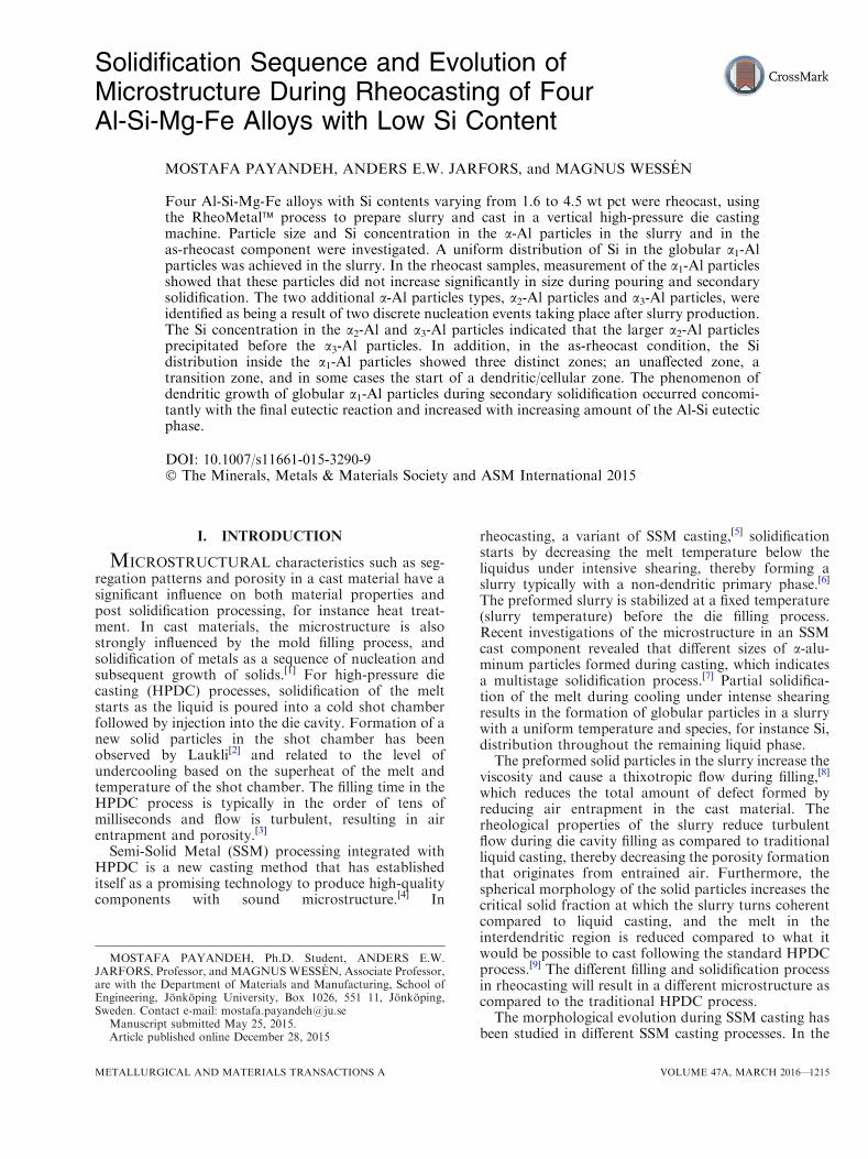
chamber Vertical Pressure Die Casting (VPDC) machinewith a vertically clamped tool. The die temperature wascontrolled using a PolyTemp� oil heater. The diesurface temperature was measured as 473 K to 493 K(200 �C to 220�C) using IR thermometer and main-tained in this interval throughout the experiments.Figure 2 schematically illustrates the sequence of foursteps in the VPDC machine as well as ejection of thefinal component. As the shot sleeve docks with the fixedmold half by means of rotation and upward motion, theslurry was injected into the die cavity. To minimizeturbulence in the injection step, the plunger speed wasset to 0.1 m/second, which resulted in a gate speed of1 m/second and a fill time of approximately 1 s. Theejector pins in the moving half of the mold ejected thepart. A schematic illustration of the final rheocastcomponent is shown in Figure 3.
B. Sampling and Measurements
Samples for microstructural evaluation from allcastings were taken from the same position in thecenter of the components and cut parallel to the fillingdirection to ensure repeatable and comparable condi-tions, as shown schematically in Figure 3. The sampleswere prepared using standard metallographic tech-niques and etched using a 10 pct NaOH solution andStruers� OP-S suspension for 5 minutes to maximizecontrast between the different phases under opticalmicroscope observation.[22] Microstructural characteri-zation was performed using an Olympus� opticalmicroscope and the Olympus Stream� image analysissystem. Particles size measurements based on imagecontrast were made on at least 5 representative imagesand 100 a-Al particles in total from each sample. To
Table I. Chemical Compositions of the Four Alloys Investigated (Mass Percentage)
Alloy Si Fe Cu Mn Mg Zn TL [K (�C)]
1 1.69 0.80 <0.01 <0.01 0.39 <0.01 919 (646)2 2.49 0.80 <0.01 <0.01 0.40 <0.01 911 (638)3 3.67 0.75 <0.01 <0.01 0.41 <0.01 907 (634)4 4.56 0.75 <0.01 <0.01 0.40 <0.01 899 (626)
1216—VOLUME 47A, MARCH 2016 METALLURGICAL AND MATERIALS TRANSACTIONS A

distinguish between slurry particles and other sec-ondary microstructural features, a particle size discrim-ination technique was used.
The Si concentration in the aluminum phase wasmeasured using a scanning electron microscope (SEM)equipped with an EDAX Apollo� wavelength disper-sive spectrometer (WDS). Pure elements were used asstandards, and the acceleration voltage was set to 10 kVfor the measurement of both Al- and Si-concentration.The compositions of the remaining melt after the slurrypreparation stage in the quenched samples of the slurryand also of the precipitated phases in the cast compo-nent were defined by using five independent energy-dis-persive X-ray spectroscopy (EDS) measurements in the
SEM machine using a fixed accelerating voltage of15 kV. The solubility limit of Si in aluminum fordifferent conditions was calculated by ThermoCalc�[23]
software, using the TCAL database.[24]
In order to use a consistent nomenclature, theglobular primary a-Al particles formed during slurrypreparation will be referred to as a1-Al particles, whilesecondary and ternary particles formed during subse-quent solidification during filling and cooling in themold cavity will be referred to as a2-Al and a3-Alparticles, respectively. The Si concentration in the a-Alphase will be given as CA
Si; where A is the position relatedto the measured point in the a-Al phase particle,thereafter succeeded by the type of particle.
Fig. 1—Manual RheoMetal� process; (1) extract the melt, (2) pour into a mold to make EEM, (3) prepare a slurry by means of stirring andEEM melting (4) pour the slurry into the shot chamber.
Fig. 2—Four steps of VPDC casting; (1) charge the chamber (2) docking (3) injection (4) punching biscuit and part ejection.
METALLURGICAL AND MATERIALS TRANSACTIONS A VOLUME 47A, MARCH 2016—1217
III. RESULTS
A. Microstructural Characteristics
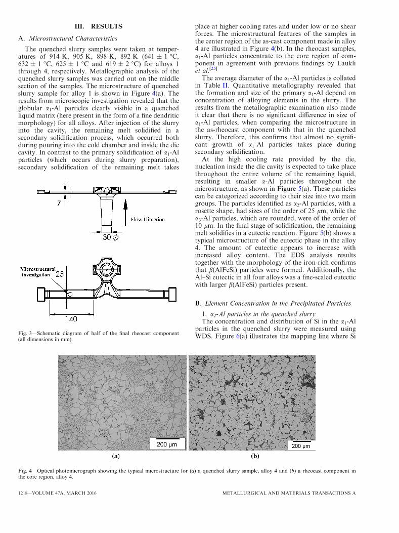
The quenched slurry samples were taken at temper-atures of 914 K, 905 K, 898 K, 892 K (641 ± 1 �C,632 ± 1 �C, 625 ± 1 �C and 619 ± 2 �C) for alloys 1through 4, respectively. Metallographic analysis of thequenched slurry samples was carried out on the middlesection of the samples. The microstructure of quenchedslurry sample for alloy 1 is shown in Figure 4(a). Theresults from microscopic investigation revealed that theglobular a1-Al particles clearly visible in a quenchedliquid matrix (here present in the form of a fine dendriticmorphology) for all alloys. After injection of the slurryinto the cavity, the remaining melt solidified in asecondary solidification process, which occurred bothduring pouring into the cold chamber and inside the diecavity. In contrast to the primary solidification of a1-Alparticles (which occurs during slurry preparation),secondary solidification of the remaining melt takes
place at higher cooling rates and under low or no shearforces. The microstructural features of the samples inthe center region of the as-cast component made in alloy4 are illustrated in Figure 4(b). In the rheocast samples,a1-Al particles concentrate to the core region of com-ponent in agreement with previous findings by Laukliet al.[25]
The average diameter of the a1-Al particles is collatedin Table II. Quantitative metallography revealed thatthe formation and size of the primary a1-Al depend onconcentration of alloying elements in the slurry. Theresults from the metallographic examination also madeit clear that there is no significant difference in size ofa1-Al particles, when comparing the microstructure inthe as-rheocast component with that in the quenchedslurry. Therefore, this confirms that almost no signifi-cant growth of a1-Al particles takes place duringsecondary solidification.At the high cooling rate provided by the die,
nucleation inside the die cavity is expected to take placethroughout the entire volume of the remaining liquid,resulting in smaller a-Al particles throughout themicrostructure, as shown in Figure 5(a). These particlescan be categorized according to their size into two maingroups. The particles identified as a2-Al particles, with arosette shape, had sizes of the order of 25 lm, while thea3-Al particles, which are rounded, were of the order of10 lm. In the final stage of solidification, the remainingmelt solidifies in a eutectic reaction. Figure 5(b) shows atypical microstructure of the eutectic phase in the alloy4. The amount of eutectic appears to increase withincreased alloy content. The EDS analysis resultstogether with the morphology of the iron-rich confirmsthat b(AlFeSi) particles were formed. Additionally, theAl–Si eutectic in all four alloys was a fine-scaled eutecticwith larger b(AlFeSi) particles present.
B. Element Concentration in the Precipitated Particles
1. a1-Al particles in the quenched slurryThe concentration and distribution of Si in the a1-Al
particles in the quenched slurry were measured usingWDS. Figure 6(a) illustrates the mapping line where SiFig. 3—Schematic diagram of half of the final rheocast component
(all dimensions in mm).
Fig. 4—Optical photomicrograph showing the typical microstructure for (a) a quenched slurry sample, alloy 4 and (b) a rheocast component inthe core region, alloy 4.
1218—VOLUME 47A, MARCH 2016 METALLURGICAL AND MATERIALS TRANSACTIONS A

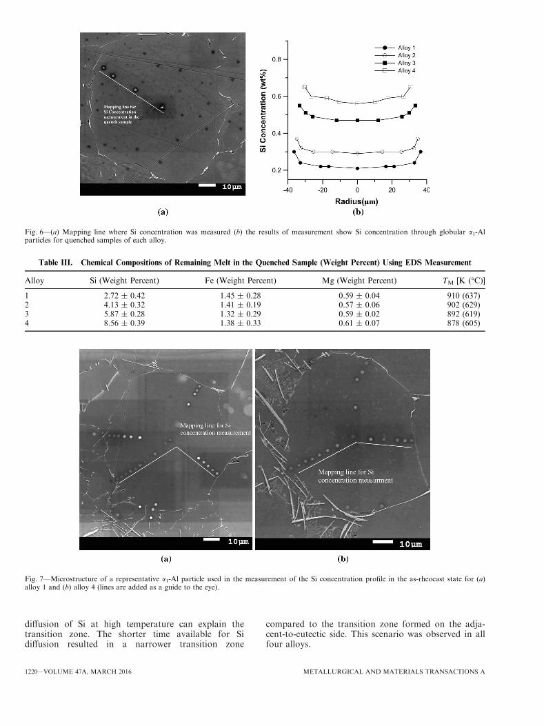
concentration was measured in a a1-Al particle. Fivepoints on a straight line from the center to the surfacewere measured for each particle. The validity of theresults was confirmed by measuring replicate points atdifferent locations in the particle but at the samedistance from the center. As shown in Figure 6(b), theSi concentration was nearly constant across the a1-Alparticles, this being a key observation. The Si concen-tration inside the a1-Al particles increased as the Sicontent in the alloy was increased. Measurements ondifferent areas of the a1-Al particle in each alloyconfirmed that the Si concentration was almost identicalat identical distances from the particle central point.
Furthermore, the composition of the liquid portion ofthe slurry was measured using EDS. The results for Si,Mg, and Fe are collated in Table III. The measurementerror was calculated based on multiple measurements indifferent areas. The small standard deviation indicates auniform distribution of alloying elements. The measure-ment indicates higher concentration of main alloyingelements in the liquid portion of the slurry.
2. a1-Al particles in the as-rheocast conditionThe distribution of Si in a1-Al particles in the
as-rheocast samples was measured using WDS. Twoparticles from alloys 1 and 4 are shown in Figure 7(a)and Figure 7(b), respectively. An important feature ofthe selected particles was that one side was separatedfrom an adjacent a1-Al particle by only a very thin layerof eutectic b(AlFeSi). This will be referred to as the‘‘adjacent-to-globular side’’, and another side was closeto the eutectic which will be referred to as the ‘‘adja-cent-to-eutectic side’’. As Figure 7 illustrates, the con-centration of Si was measured from the adjacent-
to-globular side of the a1-Al particles to the adja-cent-to-eutectic side. The additional points were mea-sured in the boundary and the critical area byconsidering the distance from the surface of the particle.The error measurement shows that the maximumdifference for points in the identical positions is around±0.03 wt pct for all alloys.Figures 8(a) through (d) shows the results from the
WDS measurements as concentration profiles of Si inthe a1-Al particles in the as-rheocast condition. Based onthese profiles, two different zones for alloy 1 and threedifferent zones for alloys 2 to 4 were distinguishable.The central unaffected zone of the a1-Al particles has anear constant concentration of Si, similar to thatobserved in the as-quenched condition in the slurry(Figure 6(b)), and the Si concentration increased in theregion near to the surface of the a1-Al particles, theso-called transition zone. The transition zones in differ-ent alloys were not identical and the width of thetransition zone depended on alloy composition, increas-ing with increasing amounts of Si in the alloy. Further-more, the width of the transition zone inadjacent-to-globular side and adjacent-to-eutectic sideof the particles was different.The most noticeable difference between the morphol-
ogy of a1-Al particles in the as-quenched condition, seeFigure 6(a), and in the as-rheocast samples, seeFigure 7, was the growth of a dendritic/cellular zonein the adjacent-to-eutectic side surface of a1-Al particles.The Si concentration in this part of the a1-Al particles,Figure 8, showed a further increase as compared to thetransition zone. In the adjacent-to-globular side inwhich the eutectic phase has no chance to grow, theresult shows no dendritic growth occurred and back
Table II. Average Diameter of the -Al Particles (lm) in the Quenched Slurry and the Rheocast Samples
Alloya1-Al in quenched
samples (lm)a1-Al in as-castcomponent (lm)
a2-Al in as-castcomponent (lm)
a3-Al in as-castcomponent (lm)
1 74 ± 6 75 ± 8 28 ± 4 14 ± 32 68 ± 7 72 ± 8 26 ± 2 12 ± 23 64 ± 6 66 ± 8 25 ± 5 12 ± 44 60 ± 4 64 ± 9 27 ± 3 11 ± 6
Fig. 5—Optical micrographs showing (a) the typical microstructure of a rheocast component in the core region and formation of additionala2-Al and a3-Al particles (b) optical microscopy showing the typical eutectic region in the alloy 4.
METALLURGICAL AND MATERIALS TRANSACTIONS A VOLUME 47A, MARCH 2016—1219
diffusion of Si at high temperature can explain thetransition zone. The shorter time available for Sidiffusion resulted in a narrower transition zone
compared to the transition zone formed on the adja-cent-to-eutectic side. This scenario was observed in allfour alloys.
Fig. 6—(a) Mapping line where Si concentration was measured (b) the results of measurement show Si concentration through globular a1-Alparticles for quenched samples of each alloy.
Table III. Chemical Compositions of Remaining Melt in the Quenched Sample (Weight Percent) Using EDS Measurement
Alloy Si (Weight Percent) Fe (Weight Percent) Mg (Weight Percent) TM [K (�C)]
1 2.72 ± 0.42 1.45 ± 0.28 0.59 ± 0.04 910 (637)2 4.13 ± 0.32 1.41 ± 0.19 0.57 ± 0.06 902 (629)3 5.87 ± 0.28 1.32 ± 0.29 0.59 ± 0.02 892 (619)4 8.56 ± 0.39 1.38 ± 0.33 0.61 ± 0.07 878 (605)
Fig. 7—Microstructure of a representative a1-Al particle used in the measurement of the Si concentration profile in the as-rheocast state for (a)alloy 1 and (b) alloy 4 (lines are added as a guide to the eye).
1220—VOLUME 47A, MARCH 2016 METALLURGICAL AND MATERIALS TRANSACTIONS A

3. a2-Al and a3-Al particles in the as-rheocast alloyAs the slurry enters the die cavity, the remaining melt
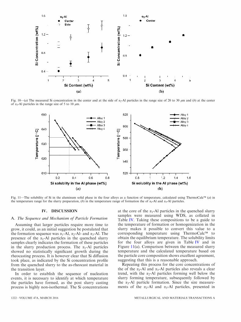
starts to solidify. In the as-rheocast material, a2-Al anda3-Al particles were observed. These were not seen in thequenched slurry samples and must therefore haveformed after the slurry was poured into the shot sleeve.Particles from a2-Al and a3-Al phases were selected ineach sample. By means of WDS, the Si concentrationswere measured at two positions—in the center and at thesurface of a2-Al particles, Figure 9 and at one positionin the center of a3-Al particles. The Si concentrations ina2-Al and a3-Al particles are shown in Figure 10. Theaverage Si concentration in the center of a2-Al particles,Figure 10(a), showed higher values than those found inthe center of the a1-Al particles but lower than thosemeasured in the center of the a3-Al particles. The Siconcentration close to the edge of the a2-Al particles wasvery close to the Si solubility at the eutectic point foralloys 3 and 4, Figure 11.
Fig. 8—The segregation profile of Si in of a1-Al particles for (a) alloy 1 (b) alloy 2 (c) alloy 3 (d) alloy 4 in the rheocast samples.
Fig. 9—Si concentration measuring positions in a2-Al particles.
METALLURGICAL AND MATERIALS TRANSACTIONS A VOLUME 47A, MARCH 2016—1221
IV. DISCUSSION
A. The Sequence and Mechanism of Particle Formation
Assuming that larger particles require more time togrow, it could, as an initial suggestion be postulated thatthe formation sequence was a1-Al, a2-Al- and a3-Al. Thepresence of the a1-Al particles in the quenched slurrysamples clearly indicates the formation of these particlesin the slurry production process. The a1-Al particlesshowed no statistically significant growth during therheocasting process. It is however clear that Si diffusiontook place, as indicated by the Si concentration profilefrom the quenched slurry to the as-rheocast material inthe transition layer.
In order to establish the sequence of nucleationevents, it is necessary to identify at which temperaturethe particles have formed, as the post slurry castingprocess is highly non-isothermal. The Si concentrations
at the core of the a1-Al particles in the quenched slurrysamples were measured using WDS, as collated inTable IV. Taking these compositions to be a guide tothe temperature of formation or homogenization in theslurry makes it possible to convert this value to acorresponding temperature using ThermoCalc� toobtain the equilibrium temperature. The solubility limitsfor the four alloys are given in Table IV and inFigure 11(a). Comparison between the measured slurrytemperature and the calculated temperature based onthe particle core composition shows excellent agreement,suggesting that this is a reasonable approach.Repeating this process for the core concentrations of
the of the a2-Al and a3-Al particles also reveals a cleartrend, with the a2-Al particles forming well below theslurry forming temperature, subsequently followed bythe a3-Al particle formation. Since the size measure-ments of the a2-Al and a3-Al particles, presented in
Fig. 10—(a) The measured Si concentration in the center and at the side of a2-Al particles in the range size of 20 to 30 lm and (b) at the centerof a3-Al particles in the range size of 5 to 10 lm.
Fig. 11—The solubility of Si in the aluminum solid phase in the four alloys as a function of temperature, calculated using ThermoCalc� (a) inthe temperature range for the slurry preparation, (b) in the temperature range of formation the of a2-Al and a3-Al particles.
1222—VOLUME 47A, MARCH 2016 METALLURGICAL AND MATERIALS TRANSACTIONS A
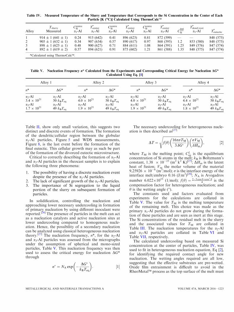
Table II, show only small variation, this suggests twodistinct and discrete events of formation. The formationof the dendritic/cellular region between the globulara1-Al particles, Figure 5 and WDS measurements,Figure 8, is the last event before the formation of thefinal eutectic. This cellular growth may as such be partof the formation of the divorced eutectic microstructure.
Critical to correctly describing the formation of a2-Aland a3-Al particles in the rheocast samples is to explainthe following three phenomena:
1. The possibility of having a discrete nucleation eventdespite the presence of the a1-Al particles.
2. The lack of significant growth of the a1-Al particles.3. The importance of Si segregation to the liquid
portion of the slurry on subsequent formation ofparticles.
In solidification, controlling the nucleation andapproaching lower necessary undercooling in formationof primary nucleation by using different inoculant werereported.[26] The presence of particles in the melt can actas a nucleation catalysts and active nucleation sites atlower undercooling compared to homogenous nucle-ation. Hence, the possibility of a secondary nucleationcan be analyzed using classical heterogeneous nucleationtheory.[27] The nucleation frequency, n*, for the a2-Aland a3-Al particles was assessed from the micrographsunder the assumption of spherical and mono-sizedparticles, Table V. This nucleation frequency was thenused to assess the critical energy for nucleation DG*through
n� ¼ NA exp � DG�
kBTeq
� �: ½1�
The necessary undercooling for heterogeneous nucle-ation is then described as[27]
DT ¼
ffiffiffiffiffiffiffiffiffiffiffiffiffiffiffiffiffiffiffiffiffiffiffiffiffiffiffiffiffiffiffiffiffiffiffiffiffiffiffiffiffiffiffiffiffiffiffiffiffifðhÞ 16prTM
3DG�
� �rVM
DHm
� �s; ½2�
where TM is the melting point; CLeq is the equilibrium
concentration of Si atoms in the melt; kB is Boltzmann’sconstant, 1.38 9 10�23 (m2 k2 K)[27]; DHm is the latentheat of fusion; Vm the molar volume of the material9,25926 9 10�6 (m3/mol); r is the interface energy of theinterface melt/embryo 0.16 (J/m2)[28]; NA is Avogadros
number 6.02291023 (1/mol); fðhÞ ¼ 2�3 cos hþcos2 h4 is the
compensation factor for heterogeneous nucleation; andh is the wetting angle (�).The constants used and factors evaluated from
experiments for the calculations are collated inTable V. The value for TM is the melting temperatureof the remaining melt. This choice was made as theprimary a1-Al particles do not grow during the forma-tion of these particles and are seen as inert at this stage.The Si concentrations of the residual melt in the slurryand the associated values for TM are collated inTable III. The nucleation temperatures for the a2-Aland a3-Al particles are collated in Table VI andTable VII, respectively.The calculated undercooling based on measured Si
concentration at the center of particles, Table IV, wasused to fit in heterogeneous nucleation equation, Eq [2],for identifying the required contact angle for newnucleation. The wetting angles required are all low,suggesting that the effective substrates are pre-wetted.Oxide film entrainment is difficult to avoid in theRheoMetal� process as the top surface of the melt must
Table IV. Measured Temperature of the Slurry and Temperature that Corresponds to the Si Concentration in the Center of Each
Particle [K (�C)] Calculated Using ThermoCalc�
AlloyTslurry
MeasuredCcentre
Sia1-Al
Tcenter*
a1-AlCcentre
Sia2-Al
Tcenter*
a2-AlCcentre
Sia3-Al
Tcenter*
a3-Al Cdendroot
Si
Tdend/root*
a1-Al Teutectic*
1 914 ± 1 (641 ± 1) 0.24 915 (642) 0.41 896 (623) 0.81 872 (599) — — 848 (575)2 905 ± 1 (632 ± 1) 0.34 907 (634) 0.57 890 (617) 0.97 868 (595) 1.2 853 (580) 848 (575)3 898 ± 1 (625 ± 1) 0.48 900 (627) 0.71 884 (611) 1.08 864 (591) 1.25 849 (576) 847 (574)4 892 ± 1 (619 ± 2) 0.57 894 (621) 0.91 875 (602) 1.21 861 (588) 1.35 848 (575) 847 (574)
*Calculated using ThermoCalc�.
Table V. Nucleation Frequency n* Calculated from the Experiments and Corresponding Critical Energy for Nucleation DG*Calculated Using Eq. [1]
Alloy 1 Alloy 2 Alloy 3 Alloy 4
n* DG* n* DG* n* DG* n* DG*
a2-Al a2-Al a2-Al a2-Al a2-Al a2-Al a2-Al a2-Al3.4 9 1021 50 kBTeq 4.0 9 1021 50 kBTeq 4.0 9 1021 50 kBTeq 4.4 9 1021 50 kBTeq
a3-Al a3-Al a3-Al a3-Al a3-Al a3-Al a3-Al a3-Al1.7 9 1021 49 kBTeq 1.9 9 1021 49 kBTeq 1.9 9 1021 49 kBTeq 1.8 9 1021 49 kBTeq
METALLURGICAL AND MATERIALS TRANSACTIONS A VOLUME 47A, MARCH 2016—1223

be penetrated by the EEM. The intense shearing duringstirring will deform and break up the oxide films anddistribute them in the melt. Following the theory ofCampbell, these oxides have one dry and one wettedsurface.[29] Dihedral angles in the Al-Si system can bevery low near the liquidus temperature, giving furthersupport to the possibility of low contact angles.[30] Thissuggests that the formation of the a2-Al particles is anevent based on re-nucleation of the primary phase for allfour alloys.
For this to be possible, the pre-existing a1-Al particlesmust be regarded as inert, or only participate in theequilibration process on a significantly different time-scale than is seen in the current process. That this maybe the case is supported by the apparent lack of growthof the a1-Al particles, Table II. A slow equilibrationprocess has also previously been reported in the litera-ture for thixoforming of A356, giving further support tothe current findings.[31] The reference for the undercool-ing is, as a consequence of the slow equilibration, theliquidus temperature of the remaining melt after slurryfabrication. This will decrease the apparent undercool-ing and as such represents a conservative measure forthe characteristics of the nucleation substrate.
In die casting processes, the heat extraction rate ishigh and high rates of nucleation are common. Underthe assumption that the primary a1-Al particles formedin the slurry-making process and the a2-Al particlesformed through heterogeneous nucleation, an analysisof the formation of a3-Al particles can be made. Theundercooling implicitly assessed, and the requiredundercooling for nucleation is shown in Table VII.The observed undercooling is significantly greater thanwas obtained for the a2-Al particles. The greaterundercooling required suggests that the a3-Al particlesare formed on a less effective substrate, but the requiredcontact angles are still small, and hence the nucleationsubstrate should also be pre-wetted. The calculatedwetting angle clearly indicated the possibility of nucle-ation of these particles in the mold with very highcooling rate. Further investigation into this is necessary
but a possible origin may be the top surface of the meltand the surface of the EEM, leading to oxide nucleifrom two different origins.
B. Formation of b(AlFeSi) and Secondary Phase
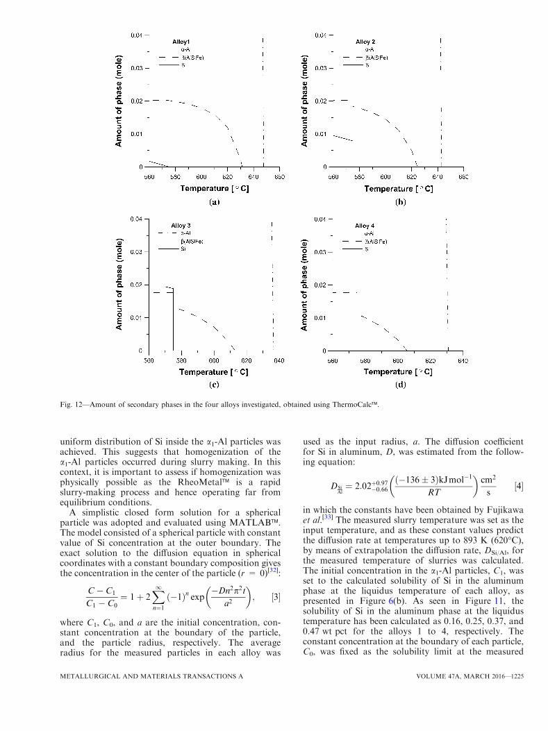
Based on the compositions of the original melt, thesequence of solidification (primary phase and eutecticreaction) was calculated using ThermoCalc�. Theresults are presented in Figure 12. According to theresults of these calculations, needle-shaped b(AlFeSi)was the most favorable eutectic phase in all four alloys,and it forms before the eutectic Si phase. The amount ofb(AlFeSi) phase is also higher than the Al-Si eutecticphase for alloys 1 to 3, in which the ratio between Fe/Siis very high. The ThermoCalc� calculation shows goodagreement with microstructural observation showing thepresence of needle-shaped b(AlFeSi) with only a minuteamount of Al-Si eutectic phase in alloy 1, Figure 6(a).Moreover, the temperature at which iron eutectic phasestarted to precipitate is close to the nucleation temper-ature of a2-Al particle precipitation calculated accordingto the Si concentrations in the center of the a2-Alparticles, Table IV. Therefore, by decreasing tempera-ture of the slurry to the binary eutectic temperature,b(AlFeSi) phase nucleates and in this process a2-Alparticles nucleate. The measures Si concentration andthe corresponding calculated temperature in the den-drite root of disturbed a1-Al particle in rheocast samplesare close to the temperature of the ternary eutecticreaction suggesting that this morphology is formed atthe very end of solidification.
C. Changes of the a1-Al Particles During Slurry Makingand Casting
1. Homogenization the a1-Al particles during slurrymakingDuring slurry making, a1-Al particles are generated
and a thermal equilibrium, the slurry temperature, israpidly established.[21] The measurements showed that a
Table VI. Undercooling in the Melt During Formation of a2-Al Particles
Alloy Tcenter [K (�C)] Calculated Undercooling (K) Wetting Angle Required to Achieve Undercooling, Eq. [2]
1 897 (624) 14 <222 891 (618) 12 <203 883 (610) 8 <174 873 (600) 3 <11
Table VII. Undercooling in the Melt During Formation of a3-Al Particles
Alloy Tcenter [K (�C)] Calculated Undercooling (K) Wetting Angle Required to Achieve Undercooling, Eq. [2]
1 872 (599) 47 <372 868 (595) 34 <353 864 (591) 28 <324 861 (588) 17 <25
1224—VOLUME 47A, MARCH 2016 METALLURGICAL AND MATERIALS TRANSACTIONS A
uniform distribution of Si inside the a1-Al particles wasachieved. This suggests that homogenization of thea1-Al particles occurred during slurry making. In thiscontext, it is important to assess if homogenization wasphysically possible as the RheoMetal� is a rapidslurry-making process and hence operating far fromequilibrium conditions.
A simplistic closed form solution for a sphericalparticle was adopted and evaluated using MATLAB�.The model consisted of a spherical particle with constantvalue of Si concentration at the outer boundary. Theexact solution to the diffusion equation in sphericalcoordinates with a constant boundary composition givesthe concentration in the center of the particle (r = 0)[32]:
C� C1
C1 � C0¼ 1þ 2
X1n¼1
ð�1Þn exp �Dn2p2ta2
� �; ½3�
where C1, C0, and a are the initial concentration, con-stant concentration at the boundary of the particle,and the particle radius, respectively. The averageradius for the measured particles in each alloy was
used as the input radius, a. The diffusion coefficientfor Si in aluminum, D, was estimated from the follow-ing equation:
DSiAl¼ 2:02þ0:97
�0:66
ð�136� 3ÞkJmol�1
RT
� �cm2
s½4�
in which the constants have been obtained by Fujikawaet al.[33] The measured slurry temperature was set as theinput temperature, and as these constant values predictthe diffusion rate at temperatures up to 893 K (620�C),by means of extrapolation the diffusion rate, DSi/Al, forthe measured temperature of slurries was calculated.The initial concentration in the a1-Al particles, C1, wasset to the calculated solubility of Si in the aluminumphase at the liquidus temperature of each alloy, aspresented in Figure 6(b). As seen in Figure 11, thesolubility of Si in the aluminum phase at the liquidustemperature has been calculated as 0.16, 0.25, 0.37, and0.47 wt pct for the alloys 1 to 4, respectively. Theconstant concentration at the boundary of each particle,C0, was fixed as the solubility limit at the measured
Fig. 12—Amount of secondary phases in the four alloys investigated, obtained using ThermoCalc�.
METALLURGICAL AND MATERIALS TRANSACTIONS A VOLUME 47A, MARCH 2016—1225
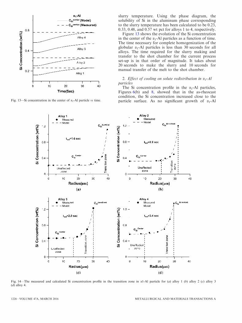
slurry temperature. Using the phase diagram, thesolubility of Si in the aluminum phase correspondingto the slurry temperature has been calculated to be 0.23,0.33, 0.48, and 0.57 wt pct for alloys 1 to 4, respectively.Figure 13 shows the evolution of the Si concentration
in the center of the a1-Al particles as a function of time.The time necessary for complete homogenization of theglobular a1-Al particles is less than 30 seconds for allalloys. The time required for the slurry making andtransfer to the shot chamber for the current processset-up is in that order of magnitude. It takes about20 seconds to make the slurry and 10 seconds formanual transfer of the melt to the shot chamber.
2. Effect of cooling on solute redistribution in a1-AlparticlesThe Si concentration profile in the a1-Al particles,
Figures 6(b) and 8, showed that in the as-rheocastcondition, the Si concentration increased close to theparticle surface. As no significant growth of a1-AlFig. 13—Si concentration in the center of a1-Al particle vs time.
Fig. 14—The measured and calculated Si concentration profile in the transition zone in a1-Al particle for (a) alloy 1 (b) alloy 2 (c) alloy 3(d) alloy 4.
1226—VOLUME 47A, MARCH 2016 METALLURGICAL AND MATERIALS TRANSACTIONS A
particles had occurred during casting of the componentand solidification process, it is essential to understand ifthis could be the result of a back diffusion process.Based on the exact solution of the diffusion equation inspherical coordinates, the Si concentration is given by[32]
C� C1
C1 � C0¼ 1þ 2a
pr
X1n¼1
ð�1Þn
nsin
npra
� �exp
�Dn2p2ta2
� �;
½5�
where r is distance from particle center. For each alloy,the measured a1-Al particle size was used for thecalculation. The initial concentration, C1, was set asthe measured Si concentration in the a1-Al particles in
the quenched slurry samples, CSlurrySi . The constant
concentration at the particle boundary was C0, which
was set to the measured value CSurfEut
Si for alloy 1 and to Cdendroot
Si
for alloys 2 through 4.The diffusivity of Si in the Al phase, DSi/Al, was
calculated using Eq. [4] for the calculated temperaturecorresponding to the Si concentration of the boundary
at the adjacent-to-eutectic side, CSurfEut
Si for alloy 1 and to
the temperature corresponding to, Cdendroot
Si for alloys 2through 4. The results are shown in Figures 14(a)through (d) for the alloys 1 to 4, respectively.
The calculated Si concentration profiles, shown asdashed lines, clearly show that the transition zone wasaffected by back diffusion from the higher concentrationregion. The time of diffusion to achieve a best fit to themeasured data was 1.6, 2.2, 2.9, and 3.4 seconds foralloys 1 through 4. It can also be seen that the time ofdiffusion during the solidification process was not thesame for the four alloys. The order of magnitudecorresponds to the time for injection (1 second fill time)plus some additional time for solidification in the diecavity. An increased Si content in the transition zone ofa1-Al particles also corresponds to an increase in theamount of eutectic Al-Si phase, Figure 12, and anincrease in the Si diffusivity in the aluminum phase dueto increased number of vacancies.
D. Formation of the Final Invariant Eutectic
In the solidification process for the remaining melt, aninvariant eutectic reaction which produces eutectic Si-and Fe-containing phases in addition to the aluminumphase will take place. The morphologies of both theb(AlFeSi) phase and the eutectic Si particles wererepresentative for the rapid cooling conditions com-monly obtained in all pressure-assisted die castingprocesses, Figure 5(c).[34] It should also be concludedthat the deviation from spherical shape of the globularparticles is a result of the increased undercooling at theend of an invariant eutectic reaction. This is supportedby the fact that the concentration of Si at the root ofdendritic part formed on the a1-Al particles correspondsdirectly to the eutectic temperature. The a3-Al particlesare not part of the final invariant eutectic reaction as
they form well above this temperature according to Simeasurement in center of these particles.
V. CONCLUSIONS
In this study, the solidification sequence in a VPDCrheocasting set-up of four Al-Si alloys from slurryfabrication and through the subsequent casting processwas investigated. The microstructure of quenched sam-ples of the slurry clearly showed that in the primarysolidification stage, globular a1-Al particles were formedduring the slurry preparation process in all four alloys.The Si concentrations measured inside the a1-Al parti-cles show a very uniform Si distribution. The temper-atures which correspond to the measured Siconcentrations calculated using ThermoCalc� werecompared with the measured slurry temperatures anda good fit was found. Applying a mathematical modelbased on diffusion equations showed that the time tomake the slurry and subsequent steps before injectioninto the die chamber was sufficient to homogenize Si inthe a1-Al particles. Moreover, EDS measurement on theliquid portion of the slurry indicated that the formationof these particles enriched the remaining melt, and theintensive shearing during stirring homogenized thealloying elements through this phase.Furthermore, the microstructural evaluation based on
size measurement exposed that in the microstructure ofrheocast components, three types of particles a1-Al, a2-Al,and a3-Al were seen. The a1-Al particles in the range sizeof 60 to 75 lm formed during slurry preparation processappear to be relatively inert and do not grow or shrinkduring pouring into the shot sleeve and during filling andsolidification process. The a2-Al and a3-Al particles werenot observed in the quenched samples of the slurry andmust therefore have formed after the slurry preparationprocess. Si concentrations measured in a1-Al particles inthe as-rheocast samples showed that the concentration ofSi in the center of particles was similar to the concentra-tions measured in the a1-Al particles in quenched slurrysamples. A limited amount of back diffusion occurred inthe shot chamber and in the die.The average Si concentration in the center of a2-Al
particle showed higher values than the Si concentra-tions in the center of the a1-Al particles but lowerthan those measured in the center of the a3-Alparticles. It was furthermore concluded that a2-Al-and a3-Al particles form during cooling, with thelarger a2-Al particles nucleated first at a highertemperature. Both particles formed below the temper-ature of the first eutectic reaction where a-Al andb(AlFeSi) precipitate as a divorced eutectic. Duringthe final invariant reaction, the ternary eutectic con-sisting of a-Al, b(AlFeSi), and Si precipitated. As thisreaction is an invariant reaction, undercooling canincrease greatly. The observed morphological deviationof the large a1-Al particles with a tendency to start toform dendritic or cellular features was regarded as aresult of this increased undercooling.
METALLURGICAL AND MATERIALS TRANSACTIONS A VOLUME 47A, MARCH 2016—1227
ACKNOWLEDGMENTS
This research was supported by the KnowledgeFoundation (RheoCom Project No. 20100203) whichis gratefully acknowledged. The authors would like tothank COMPtech AB for the supply of materials.Huawei Technologies Sweden AB is acknowledged forhelp and technical support.
REFERENCES1. J.G. Kaufman and E.L. Rooy: Aluminum Alloy Castings: Prop-
erties, Processes, and Applications, ASM International, MaterialPark, 2004, pp. 7–67.
2. S. Otarawanna, C.M. Gourlay, H.I. Laukli, and A.K. Dahle:Trans. Indian Inst. Met., 2009, vol. 62, pp. 499–503.
3. E.J. Vinarcik: High Integrity Die Casting Processes, 1st ed., Wiley,New York, 2003, pp. 13–24.
4. D.H. Kirkwood, M. Suery, P. Kapranos, H.V. Atkinson, and K.Young: Semi-solid Processing of Alloys, Springer, New York,2010, pp. 109–127.
5. M.C. Flemings, R.G. Riek, and K.P. Young: Mater. Sci. Eng.,1976, vol. 25, pp. 103–17.
6. T. Li, X. Lin, and W. Huang: Acta Mater., 2006, vol. 54,pp. 4815–24.
7. M. Hitchcock, Y. Wang, and Z. Fan: Acta Mater., 2007, vol. 55,pp. 1589–98.
8. O. Lashkari and R. Ghomashchi: J. Mater. Process. Technol.,2007, vol. 182, pp. 229–40.
9. A.K. Dahle and D.H. StJohn: Acta Mater., 1999, vol. 47,pp. 31–41.
10. O. Lashkari and R. Ghomashchi: Can. Metall. Q., 2014, vol. 53,pp. 47–54.
11. P. Das, S. Dutta, and S.K. Samanta: Inst. Mech. Eng. Part B,2013, vol. 227, pp. 1474–83.
12. J. Wang, P. Li, G. Mi, and Y. Zhong: J. Mater. Process. Technol.,2010, vol. 210, pp. 1652–59.
13. S. Nafisi and R. Ghomashchi: JOM, 2006, vol. 58, pp. 24–30.14. H. Guo, X. Yang, and B. Hu: J. Wuhan Univ. Technol. Mater. Sci.
Ed., 2008, vol. 23, pp. 54–59.
15. S. Thanabumrungkul, S. Janudom, R. Burapa, P. Dulyapraphant,and J. Wannasin: Trans. Nonferrous Met. Soc. China, 2010,vol. 20, pp. s1016–s21.
16. H. Guo, X. Yang, and B. Hu: J. Wuhan Univ. Technol. Mater. Sci.Ed., 2007, vol. 22, pp. 590–95.
17. J. Wannasin, R.A. Martinez, and M.C. Flemings: Solid StatePhenom., 2006, vols. 116–117, pp. 366–69.
18. M. Wessen and H. Cao: A Method of and a Device for Producing aLiquid-Solid Metal Composition, WO Patent, WO/2006/062,482.
19. M. Payandeh, A.E.W. Jarfors, and M. Wessen: Solid State Phe-nom., 2013, vol. 192, pp. 392–97.
20. A. Jain, L. Ratke, and A. Sharma: Trans. Indian Inst. Met., 2012,vol. 65, pp. 545–51.
21. O. Granath, M. Wessen, and H. Cao: Int. J. Cast Met. Res., 2008,vol. 21, pp. 349–56.
22. K. Geels: Metallographic and Materialographic Specimen Prepa-ration, Light Microscopy, Image Analysis, and Hardness Testing,West Conshohocken, PA, ASTM International, 2007,pp. 179–611.
23. B. Sundman, B. Jansson, and J.O. Andersson: CALPHAD, 1985,vol. 9, pp. 153–90.
24. J.O. Andersson, T. Helander, L. Hoglund, P. Shi, and B. Sundman:Calphad, 2002, vol. 26, pp. 273–312.
25. H.I. Laukli, C.M. Gourlay, and A.K. Dahle: Metall. Mater.Trans. A, 2005, vol. 36, pp. 805–18.
26. M.P. De Cicco, L. Turng, X. Li, and J.H. Perepezko: Metall.Mater. Trans. A, 2011, vol. 42A, pp. 2323–30.
27. H. Fredriksson and U. Akerlind: Solidification and CrystallizationProcessing in Metals and Alloys, Wiley, New York, 2012,pp. 179–82.
28. Z. Jian, K. Kuribayashi, and W. Jie: Mat. Trans., 2002, vol. 43,pp. 721–26.
29. J. Campbell: Complete Casting Handbook: Metal Casting Pro-cesses, Techniques and Design, Elsevier, Oxford, 2011, pp. 19–104.
30. J.A. Bailey and J.H. Tundermann: Trans. Metall. Soc. AIME,1966, vol. 236, pp. 1031–35.
31. A.E.W. Jarfors: Int. J. Cast Met. Res., 2004, vol. 17, pp. 229–37.32. J. Crank: The Mathematics of Diffusion, Oxford University Press,
New York, 1975.33. S. Fujikawa, K. Hirano, and Y. Fukushima: Metall. Trans. A,
1978, vol. 9A, pp. 1811–15.34. S. Shin, E. Kim, G. Yeom, and J. Lee: Mater. Sci. Eng., A, 2012,
vol. 532, pp. 151–57.
1228—VOLUME 47A, MARCH 2016 METALLURGICAL AND MATERIALS TRANSACTIONS A

本文献由“学霸图书馆-文献云下载”收集自网络,仅供学习交流使用。
学霸图书馆(www.xuebalib.com)是一个“整合众多图书馆数据库资源,
提供一站式文献检索和下载服务”的24 小时在线不限IP
图书馆。
图书馆致力于便利、促进学习与科研,提供最强文献下载服务。
图书馆导航:
图书馆首页 文献云下载 图书馆入口 外文数据库大全 疑难文献辅助工具