solidification microstructures: recent developments ... solidification microstructures: recent...
TRANSCRIPT

SOLIDIFICATION MICROSTRUCTURES: RECENT
DEVELOPMENTS, FUTURE DIRECTIONS p
W. J. BOETTINGER 1, S. R. CORIELL 1, A. L. GREER 2, A. KARMA 3, W. KURZ 4{,M. RAPPAZ 4 and R. TRIVEDI 5
1NIST, Gaithersburg, MD 20899, USA, 2Department of Materials Science & Metallurgy, University ofCambridge, Cambridge CB2 3QZ, UK, 3Department of Physics, Northeastern University, Boston, MA
02115, USA, 4Department of Materials, Swiss Federal Institute of Technology Lausanne, 1015Lausanne EPFL, Switzerland and 5Iowa State University & Ames Lab. USDOE, Ames, IA 50011,
USA
(Received 1 June 1999; accepted 15 July 1999)
AbstractÐThe status of solidi®cation science is critically evaluated and future directions of research in thistechnologically important area are proposed. The most important advances in solidi®cation science andtechnology of the last decade are discussed: interface dynamics, phase selection, microstructure selection,peritectic growth, convection e�ects, multicomponent alloys, and numerical techniques. It is shown howthe advent of new mathematical techniques (especially phase-®eld and cellular automata models) coupledwith powerful computers now allows the following: modeling of complicated interface morphologies, takinginto account not only steady state but also non-steady state phenomena; considering real alloys consistingof many elements through on-line use of large thermodynamic data banks; and taking into account naturaland forced convection e�ects. A series of open questions and future prospects are also given. It is hopedthat the reader is encouraged to explore this important and highly interesting ®eld and to add her/his con-tributions to an ever better understanding and modeling of microstructure development. # 2000 ActaMetallurgica Inc. Published by Elsevier Science Ltd. All rights reserved.
Keywords: Solidi®cation; Microstructure; Theory and modeling (kinetics, transport, di�usion); Casting
1. INTRODUCTION
Microstructures are at the center of materialsscience and engineering. They are the strategic link
between materials processing and materials beha-vior. Microstructure control is therefore essentialfor any processing activity. One of the most import-
ant processing routes for many materials, especiallymetals and alloys, is solidi®cation. Over the lastdecade, important advances have been made in our
fundamental understanding of solidi®cation micro-structures. Three main ingredients have contributedto this progress: (i) the development of rigorous
analytical models that have focused on both steady-state and non-steady-state microstructure evolutionwith the inclusion of nucleation for the selection ofphases; (ii) the emergence of accurate simulation
methods, and in particular phase-®eld and cellularautomata approaches, which have permitted a vali-dation of analytical theories as well as enabling pre-
dictions on grain structure and morphologicalevolution; and (iii) the development of more re®nedexperimental techniques that have led to a bettervisualization and characterization of microstructural
development. The combination of these advancesnow makes it feasible to address long standingmicrostructure formation questions with a higher
level of scrutiny and rigor, and thus to end this mil-lennium in a renaissance period where solidi®cation``science'' is ¯ourishing and solidi®cation technology
is leading to a better control of materials proces-sing. We highlight in this paper the theoretical andexperimental progress made in understanding basicaspects of microstructure formation, emphasizing
especially the critical questions that remain to beexamined in this scienti®cally highly interesting andtechnologically important area.
A decade ago, an extensive overview was givenon the topic which was based on presentations anddiscussions of the ®rst 1988 Zermatt Workshop
Acta mater. 48 (2000) 43±70
1359-6454/00/$20.00 # 2000 Acta Metallurgica Inc. Published by Elsevier Science Ltd. All rights reserved.
PII: S1359 -6454 (99 )00287 -6
www.elsevier.com/locate/actamat
pThe Millennium Special Issue Ð A Selection of Major
Topics in Materials Science and Engineering: Current
status and future directions, edited by S. Suresh.
{ To whom all correspondence should be addressed.

dedicated to solidi®cation microstructures [1]. In thepresent overview the most important ®ndings of the
second 1998 Zermatt Workshop on Solidi®cationMicrostructures are presented by the seven keynotespeakers. (Contributions to this workshop have
been published in the form of a CD [2].)The paper is organized as follows: Section 2
describes interface pattern formation models;
Section 3 considers nucleation and growth of a newphase during the growth of an existing phase;
Section 4 emphasizes the action of ¯uid ¯ow onmicrostructures; Section 5 addresses the appli-cations of the models to industrially interesting
alloys containing several solutes; Section 6 includesdi�erent numerical techniques and their potentialfor solving complex problems in which several
phenomena must be considered simultaneously topredict the microstructure.
2. INTERFACE DYNAMICS
Microstructures are formed at moving solid±liquid interfaces. In this section, the evolution ofinterface morphologies of a single phase solid grow-ing into a liquid is presented. The growth in an
undercooled melt of equiaxed dendrites is ®rstdescribed. Directional solidi®cation with planar, cel-lular and dendritic interfaces is then considered.
Some reference is also given to recent work on two-phase growth, such as eutectic and peritecticgrowth.
2.1. Equiaxed dendritic growth
During the 1980s, the study of simpli®ed modelsthat incorporate surface tension in a consistent wayled to the novel insight that dendritic growth is con-
trolled not only by the balance between di�usionand capillarity, but also in a subtle way by crystal-line anisotropy [3, 4]. This insight led to the advent
of microscopic solvability theory to predict theselected dendrite tip velocity and tip radius [5, 6].Over the last decade, this theory has been extendedto three dimensions [7] and it has even been vali-
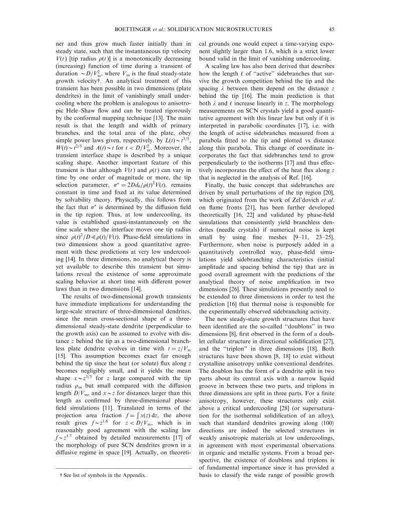
dated quantitatively by fully time-dependent simu-lations of dendritic growth in both two dimensions[8±10] and three dimensions [11] (Fig. 1), with the
added insight that in three dimensions the non-axi-symmetric tip morphology in¯uences the selectionfor large enough anisotropy.
Beyond the understanding of steady-state growthof the tip, the main new concept that has emergedover the last few years, is that complex pattern for-mation processes occurring on the much larger
scale of an entire dendrite grain structure can bedescribed by remarkably simple ``scaling laws''.These processes include growth transients [13, 14]
that lead to steady-state growth and the highly non-linear competition of secondary branches behindthe tip [15±17]. In addition, a deeper understanding
of the role of anisotropy has come from the discov-ery of new steady-state growth structures (doublons[8] and triplons [18]). Following the morphological
instability of a small spherical grain, the primarybranches of an equiaxed grain emerge along h100idirections in cubic crystals but do not immediatelyreach a steady state. These branches are much thin-
Fig. 1. Three-dimensional equiaxed dendrites calculatedwith the phase-®eld method: (a) thermal dendrite withh100i growth directions [9]; (b) solutal Ni±Cu dendritewhen the preferred growth directions are h110i instead of
h100i [12].
44 BOETTINGER et al.: SOLIDIFICATION MICROSTRUCTURES
ner and thus grow much faster initially than in
steady state, such that the instantaneous tip velocity
V(t ) [tip radius r(t )] is a monotonically decreasing
(increasing) function of time during a transient of
duration 0D=V2ss, where Vss is the ®nal steady-state
growth velocity{. An analytical treatment of this
transient has been possible in two dimensions (plate
dendrites) in the limit of vanishingly small under-
cooling where the problem is analogous to anisotro-
pic Hele±Shaw ¯ow and can be treated rigorously
by the conformal mapping technique [13]. The main
result is that the length and width of primary
branches, and the total area of the plate, obey
simple power laws given, respectively, by L�t�0t3=5,
W�t�0t2=5 and A�t�0t for t < D=V2ss: Moreover, the
transient interface shape is described by a unique
scaling shape. Another important feature of this
transient is that although V(t ) and r(t ) can vary in
time by one order of magnitude or more, the tip
selection parameter, s� � 2Dd0=r�t�2V�t�, remains
constant in time and ®xed at its value determined
by solvability theory. Physically, this follows from
the fact that s� is determined by the di�usion ®eld
in the tip region. Thus, at low undercooling, its
value is established quasi-instantaneously on the
time scale where the interface moves one tip radius
since r�t�2=DWr�t�=V�t�: Phase-®eld simulations in
two dimensions show a good quantitative agree-
ment with these predictions at very low undercool-
ing [14]. In three dimensions, no analytical theory is
yet available to describe this transient but simu-
lations reveal the existence of some approximate
scaling behavior at short time with di�erent power
laws than in two dimensions [14].
The results of two-dimensional growth transients
have immediate implications for understanding the
large-scale structure of three-dimensional dendrites,
since the mean cross-sectional shape of a three-
dimensional steady-state dendrite (perpendicular to
the growth axis) can be assumed to evolve with dis-
tance z behind the tip as a two-dimensional branch-
less plate dendrite evolves in time with t � z=Vss
[15]. This assumption becomes exact far enough
behind the tip since the heat (or solute) ¯ux along z
becomes negligibly small, and it yields the mean
shape x0z3=5 for z large compared with the tip
radius rss but small compared with the di�usion
length D/Vss, and x0z for distances larger than this
length as con®rmed by three-dimensional phase-
®eld simulations [11]. Translated in terms of the
projection area fraction f � � x�z� dz, the above
result gives f0z1:6 for z < D=Vss, which is in
reasonably good agreement with the scaling law
f0z1:7 obtained by detailed measurements [17] of
the morphology of pure SCN dendrites grown in a
di�usive regime in space [19]. Actually, on theoreti-
cal grounds one would expect a time-varying expo-
nent slightly larger than 1.6, which is a strict lower
bound valid in the limit of vanishing undercooling.
A scaling law has also been derived that describes
how the length ` of ``active'' sidebranches that sur-
vive the growth competition behind the tip and the
spacing l between them depend on the distance z
behind the tip [16]. The main prediction is that
both l and ` increase linearly in z. The morphology
measurements on SCN crystals yield a good quanti-
tative agreement with this linear law but only if it is
interpreted in parabolic coordinates [17], i.e. with
the length of active sidebranches measured from a
parabola ®tted to the tip and plotted vs distance
along this parabola. This change of coordinate in-
corporates the fact that sidebranches tend to grow
perpendicularly to the isotherms [17] and thus e�ec-
tively incorporates the e�ect of the heat ¯ux along z
that is neglected in the analysis of Ref. [16].
Finally, the basic concept that sidebranches are
driven by small perturbations of the tip region [20],
which originated from the work of Zel'dovich et al.
on ¯ame fronts [21], has been further developed
theoretically [16, 22] and validated by phase-®eld
simulations that consistently yield branchless den-
drites (needle crystals) if numerical noise is kept
small by using ®ne meshes [9±11, 23±25].
Furthermore, when noise is purposely added in a
quantitatively controlled way, phase-®eld simu-
lations yield sidebranching characteristics (initial
amplitude and spacing behind the tip) that are in
good overall agreement with the predictions of the
analytical theory of noise ampli®cation in two
dimensions [26]. These simulations presently need to
be extended to three dimensions in order to test the
prediction [16] that thermal noise is responsible for
the experimentally observed sidebranching activity.
The new steady-state growth structures that have
been identi®ed are the so-called ``doublons'' in two
dimensions [8], ®rst observed in the form of a doub-
let cellular structure in directional solidi®cation [27],
and the ``triplon'' in three dimensions [18]. Both
structures have been shown [8, 18] to exist without
crystalline anisotropy unlike conventional dendrites.
The doublon has the form of a dendrite split in two
parts about its central axis with a narrow liquid
groove in between these two parts, and triplons in
three dimensions are split in three parts. For a ®nite
anisotropy, however, these structures only exist
above a critical undercooling [28] (or supersatura-
tion for the isothermal solidi®cation of an alloy),
such that standard dendrites growing along h100idirections are indeed the selected structures in
weakly anisotropic materials at low undercoolings,
in agreement with most experimental observations
in organic and metallic systems. From a broad per-
spective, the existence of doublons and triplons is
of fundamental importance since it has provided a
basis to classify the wide range of possible growth{ See list of symbols in the Appendix.
BOETTINGER et al.: SOLIDIFICATION MICROSTRUCTURES 45

morphologies that can form as a function of under-
cooling and anisotropy [29].
2.2. Directional solidi®cation
Signi®cant progress has been made over the lastdecade in understanding fundamental aspects ofinterface dynamics in directional solidi®cation of
alloys. The onset of morphological instability indirectional solidi®cation has been modeled by theclassic Mullins±Sekerka instability [30], which pre-
dicts the instability wavelength of a steady-state pla-nar interface. In a typical directional Bridgman set-up, however, the planar interface does not becomeunstable in steady state, but during the transient
build-up of the solute boundary layer after solidi®-cation is started. By analyzing the morphologicalstability of the planar interface during this transi-
ent, and by taking into account that the instabilitytakes time to grow from natural modulations untilit becomes observable, it has been possible to
obtain for the ®rst time an accurate prediction ofthe instability wavelength [31]. This predictionagrees well quantitatively with experiments on theonset wavelength and di�ers signi®cantly from the
wavelength predicted assuming steady-state growth[32±34] (Fig. 2).The critical role of crystalline anisotropy in inter-
face dynamics has been demonstrated experimen-tally in directional growth [35]. This study exploitedthe ability to control the orientation of the crystal
grown in a thin sample. With the h100i directionoriented (nearly) parallel to the axis of the thermalgradient, the typically observed stable cellular/den-
dritic array structures are obtained [Fig. 3(a)]. Incontrast, with the h111i direction oriented normalto the glass plates, there is no second-order aniso-tropy in the plane of the sample [i.e. @ 2g�y�=@y2 � 0
where g(y ) is the surface energy and y is the polar
angle in this plane]. Thus growth in this plane is
rendered ``e�ectively isotropic'' by this judicious
choice of grain orientation. In this case, a ``sea-
weed'' structure [35] [Fig. 3(b)] whose underlying
building block is the theoretically expected doublon
Fig. 2. Wavelength of morphological instability of plane front during initial transient [31].
Fig. 3. Role of crystalline anisotropy on interface shape indirectional growth of thin transparent samples [35].
46 BOETTINGER et al.: SOLIDIFICATION MICROSTRUCTURES

[8] is formed in agreement with numerical simu-
lations also presented in Ref. [35]. This ®nding isalso consistent with the numerical ®nding that stan-dard cellular structures are linearly unstable in the
absence of crystalline anisotropy, except in a verynarrow range of velocity near onset of instability[36].
The formation of doublons and triplons has alsobeen suggested to play an important role in the for-
mation of ``feathery'' grains in aluminum alloys.This peculiar morphology, known since the 1940s,which appears as a succession of lamellae separated
by straight and wavy boundaries, was associatedwith the formation of twins parallel to the lamellaebut the appearance mechanisms remained unclear.
Recent electron back-scattered di�raction (EBSD)observations combined with detailed optical and
scanning electron microscope (SEM) observations[2, 37] have clearly shown that feathery grains aremade of h110i columnar dendrites [Fig. 1(b)], whose
primary trunks are aligned along and split in theircenter by a (111) coherent twin plane. The impinge-ment of secondary h110i side arms gives rise to
incoherent wavy twin boundaries. The switch fromh100i to h110i growth morphologies was attributed
to the small anisotropy of the solid±liquid inter-facial energy of aluminum which can be changed bythe addition of solute elements such as Zn, Mg or
Ti and possible attachment kinetics e�ects. Moredetails of this kind of growth may be found in Ref.[12].
A new experimental technique has been devel-oped in which a brief spatially periodic u.v. laser
pulse is applied to the solid±liquid interface in atransparent organic system (succinonitrile±cou-marin), to force a desired wavelength of the mor-
phological instability [38]. These experiments havemade it possible to investigate systematically thedynamical selection and stability of cellular struc-
tures by varying the instability wavelength, andthus accessing cell spacings that are not normallyaccessible from a planar interface.
A stability analysis of dendritic arrays [39] hasbeen carried out in the limit where the primary spa-
cing is larger than the di�usion length. The basicinstability found to limit the array stability at smallspacing corresponds to a mode where one out of
every two dendrites in the array is eliminated inagreement with experiments [40, 41]. The same
mode is found numerically to limit the array stab-ility of cells [36] such that its existence appearsrather universal. A range of interdendritic spacings
is therefore stable, in agreement with experimentalobservations [42, 43], but experiments with thesame ``history'' lead to a reproducible spacing [44,
45]. As an elaboration of this work, a model of``history-dependent'' selection of the primary spa-cing has been developed. This model is based on
the picture that dendrites are eliminated continu-ously (subject to this instability) during the long
transient that follows the initial morphologicalinstability of the planar interface and leads to
steady-state growth of the array with a ®nal selectedspacing [31]. The predictions of this model agreereasonably well with one set of experiments [44].
Moreover, at a more qualitative level, it has beendemonstrated experimentally that the initialinstability wavelength does indeed in¯uence the
steady-state interdendritic spacing [46].Cellular/dendritic arrays have also been modeled
numerically based on the traditional view that the
structure with the lowest undercooling is selectedwithin some stability band of spacings [47]. Thismodel has had some success in explaining exper-imental data. It does not, however, control the
strength of crystalline anisotropy, which is nowunderstood to crucially in¯uence the cellular arraystability both numerically [36] and experimentally
[35]. Therefore, its validity remains to be furtherinvestigated. An analytical approach to the primaryspacing problem by summation of the Ivantsov
®elds and application of the minimum undercoolingcriterion has also been developed recently [48].A detailed experimental study has brought new
insights into the onset of sidebranching in direc-tional solidi®cation [49]. In these experiments, thecell spacing was made uniform along the array andvaried by exploiting the history dependence of
wavelength selection in this system. This techniquewas used to characterize the onset of sidebranchingsystematically and shows that branched and non-
branched cells in these experiments belong to thesame branch of steady-state growth solutions.Furthermore, it has revealed that the thermal gradi-
ent plays a destabilizing role (i.e. increasing Gcauses non-branched cells to branch). Theoreticalmodels remain to be developed to explain this roleas well as to characterize the onset of sidebranch-
ing.
2.3. High velocity microstructures
Signi®cant experimental studies on microstructureformation under rapid solidi®cation conditions havebeen carried out in the last decade using the laserscanning technique (a type of directional growth
process) and levitational techniques (undercooledsolidi®cation).At high rates oscillatory behavior of the solid±
liquid interface (banding) has been analyzed by sev-eral authors [50±52]. Band formation in the velocityregime of strong variation of the distribution coe�-
cient, k(V ) [53], was shown to depend strongly onthe coupling of non-steady-state heat and solutetransport phenomena [52]. Experiments on the ab-
solute stability of SCN have been undertaken [54]and it was shown that close to this limit, cells fol-low a l1:5V � constant relationship [55].In highly undercooled levitated melts systematic
BOETTINGER et al.: SOLIDIFICATION MICROSTRUCTURES 47

measurements have been undertaken under others
by the group of Herlach [56]. These authors have
shown that over a substantial range of undercool-
ings good agreement may be obtained between the
measurements in a large number of metals and
alloys and the analytical model using the transport
solution of Ivantsov together with Marginal
Stability arguments including solute trapping e�ects
(a theory which we call the IMS model) [57±59],
with the stability parameter s� � �4p2�ÿ1: Further ithas been recently shown that excellent agreement
with no adjustable parameters can be obtained withthis theory [60]. Note that this agreement shouldonly be interpreted to mean that marginal stability
arguments, although not fundamentally correct, arestill useful to make quantitative predictions of den-drite growth rates in rapidly solidi®ed binary alloys.
A detailed comparison of solvability and marginalstability theory for rapid dendrite growth hasrecently been carried out [61].
One of the important observations at high under-cooling is the formation of very ®ne-grained struc-tures over a range of large undercoolings. This ®ne-grained structure has been explained by dendrite
fragmentation. At very high undercooling, as thedendrite trunk diameter becomes very ®ne, the ten-dency to undergo Rayleigh instability increases. A
theory has been developed which shows that frag-mentation can occur when the characteristic timefor dendrite break-up is shorter than the post-reca-
lescence or plateau time in overall agreement withexperiments [62, 63].
2.4. Coupled and simultaneous growth
Even if most of the recent modeling was con-
cerned with single-phase growth phenomena, therehas also been some work on coupled or simul-taneous growth of two phases. A detailed numericalsurvey of the morphological instabilities of lamellar
eutectics has been carried out in two dimensions bythe boundary integral method for the transparentorganic system CBr4±C2Cl6 [64] (Fig. 4). In parallel,
a detailed experimental survey of these instabilitieshas been carried out in the same system [65]. There
Fig. 4. Calculated stability diagram for two-dimensionalcoupled eutectic growth in CBr4±C2Cl6 [64] in excellentquantitative agreement with the experimentally measureddiagram in the same alloy [65]. Z: reduced concentrationwith the eutectic point at Z � 0:3; L: lamellar spacing nor-malized by the spacing corresponding to minimum under-cooling. The basic axisymmetric state is stable within thecenter region. Other states include steady-state tilted pat-terns (T), 2lO (spatial period doubling oscillations), 1lO(spatial period preserving oscillations), where both 1lOand 2lO oscillations can be either axisymmetric or tilted.Blank regions of the diagram are those in which the
dynamics is not yet fully understood.
Fig. 5. Quenched liquid±solid interface of simultaneous two-phase growth in peritectic Fe±Ni alloy [66].
48 BOETTINGER et al.: SOLIDIFICATION MICROSTRUCTURES

is a remarkably good quantitative agreementbetween simulations and experiments concerning
the regions of stability of both non-tilted and tiltedsteady states in the plane of composition and eutec-tic spacing, and the oscillatory instabilities that
limit these regions. This understanding of eutecticstability, however, is restricted to two dimensionsand presently needs to be extended to three dimen-
sions. Eutectic cells and dendrites forming in multi-component alloys have also been studiedtheoretically and experimentally and are presented
in Section 5.Simultaneous growth of two phases in the form
of oriented ®bers and lamellae has been observed insome peritectic alloys. Figure 5 shows an example
from a Fe±Ni alloy. For this to happen, the compo-sition has to be between the two solid phases andthe G/V ratio close to the limit of constitutional
undercooling for the stable phase with the smallerdistribution coe�cient [66±68]. This interesting insitu growth phenomenon still waits for a theoretical
interpretation, although recent phase-®eld calcu-lations have shown the formation of such a struc-ture [69].
3. PHASE AND MICROSTRUCTURE SELECTION
A microstructure is de®ned by the morphology,size, distribution, crystal orientation, and corre-
lation (texture), and number of phases. Phase andmicrostructure selection describes the variety ofphases and microstructures that develop under
given growth conditions and growth geometries.This section treats mainly transformations of phasesand microstructures from one structure or mor-phology into another. It is not so much the for-
mation of a single growth form itself which is ofinterest in this part of the paper (this has beentreated in Section 2) but the mechanisms of change
from one phase and morphology into another. Adetailed theory of the mechanisms responsible forthis selection is only at its very beginning. A well-
known empirical approach that is consistent withmany experimental results uses extremum criteria,such as the highest growth temperature in direc-tional growth. In undercooled solidi®cation proces-
sing the highest nucleation temperature and thehighest growth rate control the ®nal appearance ofmicrostructures and phases.
In many materials, additional phase transform-ations take place in the solid state which lead to the®nal microstructure. In this review only solidi®ca-
tion will be discussed. In general all solidi®cationprocesses start with nucleation and continue withgrowth. The ®nal phases may be controlled by
nucleation, by growth, or by a combination ofboth. In all three cases that will be treated separ-ately in the following, much progress has beenmade in recent years.
3.1. Nucleation control
If su�ciently large undercoolings can be attained
through hindrance of heterogeneous nucleation,
then there may be access to a variety of metastable
phases, such phases having lower melting points
and liquidus temperatures. The importance of
nucleation is seen when dealing with phase selec-
tion. A typical process where nucleation plays a
dominant role is solidi®cation processing of under-
cooled melts such as is observed in droplets [56].
There may be a spread in nucleation temperatures
even under nominally identical conditions, and con-
sequently the results are best displayed on ``micro-
structure-predominance maps''. Such maps have
been constructed for binary alloys, with alloy com-
position and droplet diameter as coordinates [70±
72]. It is found that: (i) microstructure correlates
very strongly with droplet diameter (which deter-
mines the availability of nucleant sites and the cool-
ing rate); (ii) the e�ects of processing conditions
(e.g. gas purity in atomization) can be taken into
account; and (iii) correlation with undercooling can
be found through comparison with controlled
undercooling experiments and growth modeling [71,
73] (Fig. 6). It is clear, though, that we are very far
from being able to predict nucleation undercoolings,
the diversity of potential heterogeneous nucleants
being a key impediment to quantitative modeling of
most real situations.
Under given conditions it is usual for one phase
to dominate, but the primary phases can also be
mixed. A well-analyzed example is the duplex parti-
tionless solidi®cation of b.c.c. and f.c.c. phases in
the Ni±V system [74]. There are many examples in
which the phase competition is between b.c.c. and
f.c.c. phases, and this has been most closely exam-
ined for Fe±Ni. In undercooled levitated droplets,
Fig. 6. Phase predominance map (drop diameter vs com-position) for undercooled growth in Fe±Ni alloys [73].
BOETTINGER et al.: SOLIDIFICATION MICROSTRUCTURES 49

the prevalence of one phase or the other can be
fairly well predicted by which phase has the lowerwork of nucleation (Fig. 6) (e.g. Ref. [75]). Theb.c.c. phase is easier to nucleate than would be
expected from its relative thermodynamic stability;it has a lower solid±liquid interfacial energy. In theFe±Ni±Cr system, it has been shown that the f.c.c.
or b.c.c. phase can be selected through the use ofan appropriate substrate put in contact with the
droplet to trigger solidi®cation [76].The existence of the true primary phase is some-
times revealed by a double recalescence phenom-
enon [75]. In this way, for example, the transientexistence of a hitherto unknown metastable f.c.c.
phase of rhenium has been inferred [77].Observations of this kind, found also in some alloysystems [78], may be crucial in analyzing nucleation
kinetics.Particular interest has centered on analyzing het-
erogeneous nucleation kinetics. Basic treatments of
heterogeneous nucleation (taking into account vari-ations of potency and population) have had success
in predicting primary phase selection [79]. Recentadvances have been made by studying liquid dro-plets entrained in solid matrices; when large under-
coolings �> 50 K� are required for heterogeneousnucleation, the classical spherical cap model seemsto work well, but for more potent nuclei it breaks
down [80]. In that case, some success has beenachieved with a model that considers the thermo-
dynamics, if not yet the kinetics of adsorption [81].Further heterogeneous nucleation studies have beenundertaken on liquid droplets in an emulsifying or-
ganic liquid; taking a more classical approach, roleshave been identi®ed for di�erent types of stationaryand moving surface steps [82]. Yet another advance
has been transmission electron microscopy of het-erogeneous nuclei formed in a glassy matrix [83];
this study, of relevance for commercial grain re®ne-ment of Al, shows the importance of crystallogra-phy and chemistry in nucleation, even though
quanti®cation of these roles remains elusive [84].So far, it has been natural to concentrate on the
primary stage of solidi®cation, yet there are caseswhere the interest is in the formation of secondaryphases in the ®nal stages of solidi®cation. An
example of considerable industrial interest is theDC casting of very dilute Al alloys. In cases ofpractical importance there is a range of intermetal-
lics which can nucleate, the phase selection beingsensitive to many parameters including solidi®cation
velocity. Directional solidi®cation can revealchanges in intermetallic selection and be a basis forunderstanding fundamental mechanisms [85, 86].
Attempts to analyze phase selection have focusedon comparative eutectic growth kinetics [87], but
solid-state changes and nucleation e�ects have alsobeen considered. It appears that a quantitative
analysis of the phase selection may depend on thegeometry of the liquid in which the rival intermetal-lics nucleate and grow; such an analysis has yet to
be attempted. Considerations so far suggest that thewide range of conditions over which mixtures ofphases are obtained is indicative of a growth com-
petition [88].
3.2. Growth control
Growth-controlled phase and microstructureselection has been successfully treated by comparingthe steady-state interface response of competing
phases. Calculating the interface response, i.e. thegrowth behavior of plane front, cells and dendrites,for all possible phases one can determine the
growth form which develops the highest interfacetemperature for a given growth velocity and tem-perature gradient [89] or the highest growth velocityfor a given undercooling{. Growth of eutectic struc-
tures can also be included in this treatment. Theextremum criterion is a strong indication of thestructure to be formed. It assumes that: (i) the
microstructure selection is not nucleation controlled(i.e. nucleation undercooling is su�ciently small);(ii) interaction between competing growth forms is
negligible; and (iii) steady-state theory can beapplied. Despite its simplicity this approach is ofgreat help in determining microstructure maps for amore rational alloy development. Several cases of
recent modeling of microstructure selection will bepresented in the following.
3.2.1. Stable to metastable phase transition. Usingthe above-mentioned maximum temperature cri-
terion, the stable to metastable transition for direc-tional dendrite growth has been analyzed forperitectic systems [90±92]. This allows us to ration-
alize why at high velocities a transition from astable to a metastable peritectic phase is oftenobtained. For example in Fe±Ni or Fe±Ni±Cr
steels, high weld speeds lead to the formation ofaustenite dendrites [93±95], even if at low velocitiesferrite is the primary phase, with important conse-quences for the integrity (solidi®cation cracking) of
the weld. No nucleation is needed for this transitionto occur as the metastable phase (austenite) growsinbetween the stable phase due to microsegregation
and its growth is accelerated with velocity until themetastable phase becomes the leading one. For thereverse case (metastable to stable phase) this is not
true and nucleation is a necessary requirement forthe transition to happen (see under mixed control).Similar stable to metastable phase transitions have
been analyzed in detail for Fe±C alloys [96].Under conditions of rapid solidi®cation, solute
and disorder trapping become signi®cant in the kin-etics [97]. By including such e�ects it has been poss-
{ In this approach cells and dendrites are treated as one
entity with one growth equation.
50 BOETTINGER et al.: SOLIDIFICATION MICROSTRUCTURES

ible quantitatively to model the growth kinetics inundercooled Ni±Al alloys [98, 99]. Growth kineticsalone can be used to follow the competition
between the ordered and disordered version of onephase. However, prediction of which basic structure(b.c.c. vs f.c.c. again in this case [98]) will beobserved requires a modeling of the nucleation
which does not yet exist.
3.2.2. Dendrite to eutectic transition (CZ). The
limits of the so-called ``Coupled Zone'' representthe transition between fully eutectic structure andprimary dendrites or cells with interdendritic eutec-
tic. This transition which is also hysteretic in natureis inherently di�cult to model. Karma has madeprogress in this matter and his results on the stab-ility of eutectic growth are discussed in Section 2.
Using steady-state growth theory and the extre-mum criterion for the interface temperature, this
transition can be calculated for directional growth(Bridgman, laser treatment, etc.) and is found to bein good agreement with experimental evidence
[100]. In this way, following the early work ofBoettinger et al. [101], a series of solidi®cationmicrostructure selection maps has been obtained in
recent years which allows a more rational approachto the solidi®cation processing of technically im-portant alloys: Al±Cu [102, 103], Al±Fe [104], Al±Si
[105], Al±Cu±Si [106], Ni±Al [99], and even cer-amics such as Al2O3±ZrO2 [107]. These maps havebeen used as a tool for analyzing and predicting themicrostructures of laser surface treated materials. A
similar approach, but for undercooled melts with acorresponding maximum velocity criterion, has alsobeen developed [108].
Another way of this type of microstructure mod-eling is the ``inverse modeling'' which starts with in-formation about the microstructure and optimizes
the input parameters such as the phase diagram[103, 109±111] (Fig. 7). This new approach to deter-mine stable and especially metastable phase equili-
bria is useful in cases where conventionaltechniques do not work.
3.3. Mixed control
Mixed control is always found when both nuclea-tion and growth play a controlling role in themicrostructure selection, such as in the columnar toequiaxed transition of dendritic or eutectic struc-
tures or in low velocity microstructures in the two-phase region of peritectic systems.
3.3.1. Columnar to equiaxed transition (CET).Hunt's classic approach to model the CET [112] hasbeen applied to welding [113] and has been
extended by using more recent dendrite models[114, 115]. In this way critical growth conditions forthe single crystalline welding of single crystal gas
turbine blades could be established and a poten-tially interesting process for lifetime extension ofthese expensive components developed (Fig. 8)[116].
The transition from the outer equiaxed zone tothe columnar region (ECT), often observed in cast-ings can be understood in terms of the same CET
criterion. Such considerations were made for theshape of grains continuously nucleating and grow-ing in a thermal gradient [117]. When the ratio G/V
increases up to a critical value, the shape factor ofthe grains becomes in®nite, meaning that theequiaxed grains become columnar. In order to
explain the ECT, it is necessary to consider the heattransfer coe�cient between the casting and themould (which changes strongly when solidi®cationstarts) and the superheat of the melt. Such model-
Fig. 7. Calculated microstructure selection map (V±Codiagram) for Ni±Al alloys (b), and optimized phase dia-gram (a) [109]. (The di�erence of the eutectic temperatureof b±g ' and b±g eutectic is less than the width of the line.)
BOETTINGER et al.: SOLIDIFICATION MICROSTRUCTURES 51
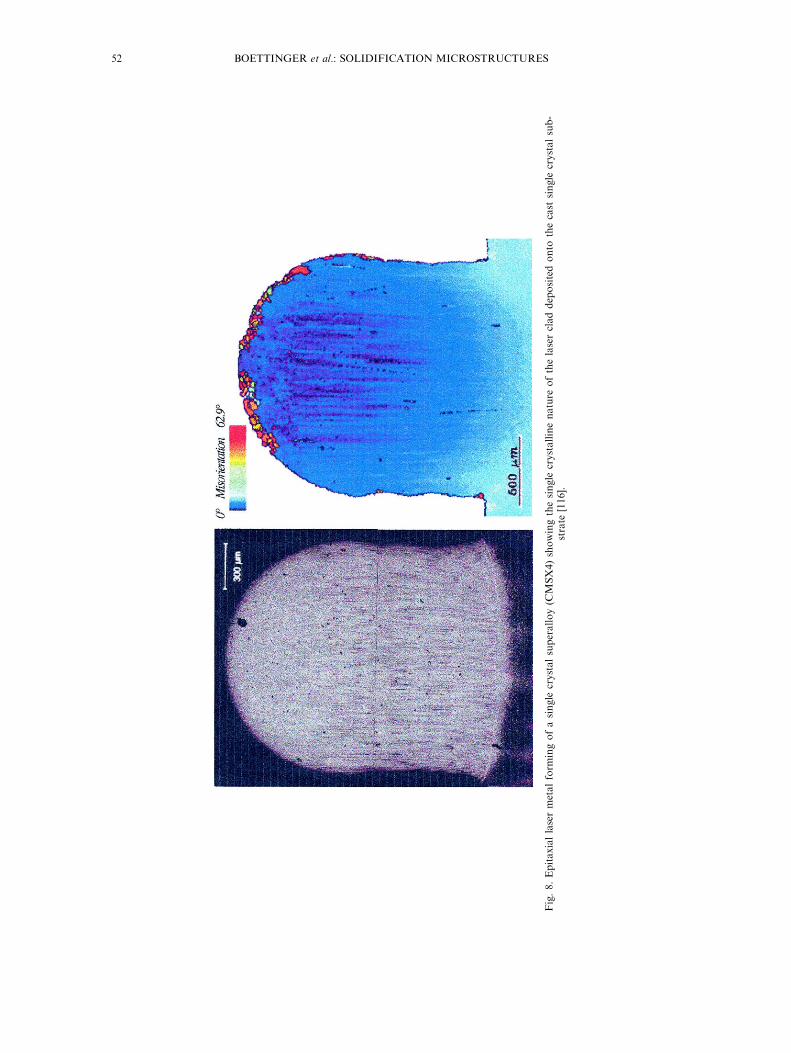
Fig.8.Epitaxiallasermetalform
ingofasingle
crystalsuperalloy(C
MSX4)showingthesingle
crystallinenature
ofthelasercladdepositedonto
thecast
single
crystalsub-
strate
[116].
52 BOETTINGER et al.: SOLIDIFICATION MICROSTRUCTURES

ing asks for a numerical approach such as theCellular Automaton technique.
3.3.2. Stable/metastable phase selection in peritec-tics close to the limit of constitutional undercooling.
In the two-solid phase region of peritectic systems,a wide spectrum of complex microstructures isfound to form under directional solidi®cation con-
ditions depending upon both the nucleationdynamics and the growth competition between thenucleated and the parent phase. Recently this has
produced a strong interest in peritectic growth[118]. At low G/V ratios, where the primary phasegrows with a non-planar interface, the microstruc-ture formation can be described by the basic ideas
developed for cellular and dendritic growth. The
major di�erence in this case is that the intercellular
or interdendritic region will show peritectic phases
whose structure can be planar, cellular or dendritic
depending on the composition gradient in the inter-
cellular/interdendritic region that is determined by
the growth conditions. However, when the G/V
ratio is increased, more complex microstructures
can form in the two-phase region under steady-state
or non-steady-state growth conditions. The for-
mation of new phases occurs during the transient
growth condition via nucleation on or ahead of the
moving interface. The actual microstructure selec-
tion process is thus controlled by nucleation of the
Fig. 9. Phase diagram (a) and G/V±Co diagram (b) for Fe±Ni alloys showing the regions of variousgrowth morphologies [119].
BOETTINGER et al.: SOLIDIFICATION MICROSTRUCTURES 53

two phases, and by growth competition between thenucleated grains and the pre-existing phase under
non-steady-state conditions. In this case the simpleextremum growth criterion does not lead to the
right answer and nucleation in the constitutionally
undercooled zone ahead of the growth front has tobe taken into account in order to determine the
microstructure selection [119, 120] (Fig. 9).
A clear understanding of complex microstructureformation has come from directional solidi®cation
studies of binary alloys with compositions in thetwo-phase region of the peritectic phase diagram at
large G/V ratio to suppress the morphologicalinstability of both the parent (a ) and the peritectic
(b ) phases, i.e. each phase alone would grow as a
planar front. Even in this simpli®ed case, a rich var-iety of microstructures has been identi®ed that
depend sensitively upon the relative importance ofnucleation, di�usion and convection [121±125] as
shown in Fig. 10. These microstructures can bebroadly classi®ed into the following groups based
on geometrical patterns and the underlying trans-
port mechanisms: (a) discrete bands of the twophases; (b) partial bands or particulates (or islands)
of one phase in the matrix of the other phase; (c)single primary to peritectic phase transition; (d)
simultaneous growth of the two phases with a pla-nar solid±liquid interface; (e) dispersed phases due
to nucleation ahead of the interface; and (f) oscillat-
ing continuous tree-like structures of the primaryphase that are surrounded by the peritectic phase
[122]. Theoretical models and experimental studiesin very thin samples have shown that structures
(a)±(e), can form under di�usive regimes, whereasmicrostructure (f) is a novel microstructure whose
formation requires the presence of oscillatory con-vection in the melt.
In order to understand the formation of some of
the complex microstructures in the two-phaseregion of peritectic systems, an analytical model of
banding in peritectic systems was ®rst proposed for
di�usive growth in which the change in phasesoccurred when the appropriate nucleation under-
coolings were reached [126]. According to thismodel, a banding cycle of alternate nucleation and
growth of primary, a, and peritectic, b, phases maycontinue, leading to an oscillatory behavior of the
interface and to alternate bands of a and b. The
major predictions of this di�usive banding modelare: (i) the banding cycle will operate below and
above the peritectic temperature; and (ii) the band-ing window exists only for a narrow range of initial
alloy composition in the hypoperitectic range.
In the above one-dimensional model of discreteband formation, it was assumed that the nuclei of
the new phase spread rapidly in the lateral direc-tion, so that no appreciable lateral gradients exist.
However, this is generally not valid and one mustconsider the relative rates of spreading of the new
phase and the continuing growth of the parent
phase. The microstructure for this complicated casewas investigated experimentally as well as by nu-
merical simulation of a two-dimensional transientphase-®eld model for a generic peritectic phase dia-
gram [69]. Several new morphologies were observedand predicted depending on the nucleation rate.
Fig. 10. Fluid ¯ow controlled microstructures in peritectic alloys: (a) discrete bands of the two phases;(b) partial bands or islands of one phase in the matrix of the other phase; (c) single primary to peritec-tic phase transition; (d) simultaneous growth of the two phases with a planar solid±liquid interface; (e)dispersed phases due to nucleation ahead of the interface; (f) oscillating continuous tree-like structures
of the primary phase that are surrounded by the peritectic phase [122].
54 BOETTINGER et al.: SOLIDIFICATION MICROSTRUCTURES

The results of the phase-®eld model indicate thatwhen only a single nucleus is allowed to form on
the wall of the sample, discrete band formation in adi�usive regime is only possible for a ®nite range ofsystem sizes, Lmin < L < Lmax, where L is the size of
the sample or the distance between the nuclei.Moreover, this range depends on both the compo-sition inside the hypoperitectic region, and the
nucleation undercoolings of the two phases. Forinternuclei distance L < Lmin, discrete particles ofthe b phase form inside the a matrix, and for
L > Lmax, discrete particles of a phase form in the bmatrix form. In addition to the microstructure ofdiscrete particles of one of the two phasesembedded inside the continuous matrix of the other
phase, more complex microstructures, including twosimultaneously growing phases form [Fig. 10(d)].Simultaneous two-phase growth has been observed
in several peritectic systems, including Sn±Cd [122],Al±Ni [67], and Fe±Ni [66] (see also Section 2.4).The basic model of nucleation and growth con-
trolled structures shows that di�erent microstruc-tures can form only within a narrow band ofcomposition in the hypoperitectic region. However,
several experimental observations of banded struc-tures have been made for compositions outside thisbanding composition window, and banding struc-tures were reported even for hyperperitectic compo-
sitions. These observations clearly indicate that theobserved structures are not controlled by di�usionbut by convection e�ects, as shall be discussed in
the following section.
4. CONVECTION EFFECTS
Convection e�ects are of utmost importance in
the development of solidi®cation microstructures.Despite this fact, most microstructure models arebased on purely di�usive transport mechanisms.
Only recently, modeling of growth in the presenceof convection has been successfully undertaken. The®rst step in such an undertaking is modeling of con-vection and its instabilities before coupling of con-
vection and microstructure formation is done.
4.1. Convection instabilities
For the simple problem of an in®nite layer withvertical temperature and solutal gradients, it is well
known that convective instabilities can occur even ifthe net density of the liquid decreases with height[127]. Similar behavior also occurs in a porous med-
ium [128]. However, usually the temperature andsolute concentration in the mushy zone of a binaryalloy are coupled by the phase diagram and this
prohibits double-di�usive behavior, i.e. a densityinversion is necessary for the onset of convectiveinstability. Worster [129] has reviewed recent workon convection in mushy zones. The critical
Rayleigh numbers for the onset of convection in abinary alloy have been calculated for three di�erent
models of the mushy zone during directional solidi-®cation [130]. In general, there are two modes ofinstability: a mode in the mushy layer and a bound-
ary-layer mode in the melt; the wavelength of themushy-layer mode is small compared with thewavelength of the boundary-layer mode. In addition
to these non-oscillatory modes, there are modesthat are oscillatory in time.The radial segregation due to solutal convection
during the directional solidi®cation of lead±thalliumalloys with a planar crystal±melt interface has beencalculated using pseudo-spectral methods [131].Solutal Rayleigh numbers for the calculations ran-
ged from very near the onset of convective instabil-ity to a factor of ten above the instability onset. Ingeneral, the ¯ows and segregation are asymmetric,
although for special conditions axisymmetric ¯owscan occur.A sudden change in ¯ow conditions is correlated
with the interface concentration during directionalsolidi®cation of a tin±bismuth alloy [132]. Theinterface concentration was monitored by Seebeck
measurements using the MEPHISTO furnaceduring the USMP-3 space¯ight. Numerical calcu-lations of the ¯uid ¯ow and solute redistributiondue to sudden gravitational accelerations caused by
thruster activation were in good agreement with theobserved Seebeck signals.
4.2. Field e�ects
It is well known that a uniform magnetic ®eldcan damp convective motions in an electrically con-ducting ¯uid. However, when a gradient in the
Seebeck voltage exists in the presence of a magnetic®eld and temperature gradients, there can be aresulting ¯ow [133, 134]. This can occur at a crys-
tal±melt interface when there is a temperature gra-dient along the interface; for example, in a binaryalloy with a non-uniform concentration. Since this
thermoelectric magnetohydrodynamic ¯ow occursin the vicinity of the interface, it can play a signi®-cant role in solute redistribution. It can also beused to counteract buoyancy-driven ¯ow in the
mushy zone during horizontal directional solidi®ca-tion [135]. Freckle formation in copper±silver andaluminum±copper alloys have been examined under
di�erent magnetic ®elds. The observed larger den-drite spacings agree with the observation in spaceexperiments where the ¯ow is signi®cantly reduced
[136].There have been a number of studies of crystal
growth in very high gravitational ®elds using a cen-
trifuge [137±139]. For germanium±gallium alloys,solute segregation exhibits a minimum as a functionof rotation rate. This behavior can be understoodby considering non-axial temperature gradients; at
BOETTINGER et al.: SOLIDIFICATION MICROSTRUCTURES 55

low rotation rates, the ¯uid velocity is decreased bythe action of Coriolis forces, while at large rotation
rates the buoyancy force due to the centrifugalacceleration, increasing as the square of the rotationrate, becomes dominant [139]. Thus, the ¯ow and
segregation are reduced at intermediate rotationrates.
4.3. E�ect of ¯ow on interface morphology
The e�ect of simple ¯ows on the shape of par-ticles growing from a supersaturated solution hasbeen calculated [140]. The concentration and ¯uid
¯ow ®elds are solved numerically by a mappingtechnique in the Stokes ¯ow approximation. Simplebase ¯ows such as a uniform streaming ¯ow or a
biaxial straining ¯ow lead to non-spherical shapes.The particle shape, as function of the ¯ow magni-tude and the anisotropy of the crystal±¯uid surface
tension, has been studied.The in¯uence of convection on morphological
instability and interface structure during directionalsolidi®cation was examined theoretically [141].
There have also been observations on massivetransparent specimens [142] which have revealedthat convection results in a gradient of microstruc-
ture along the interface, from a smooth interface todendrites. Fluid ¯ow e�ects at the very scale of themicrostructure have been seen during solidi®cation
of faceting transparent systems (e.g. salol-basedalloys) where saw-tooth patterns of millimeter sizeform [143]. Surface tension-driven convection due
to the presence of ¯uid±¯uid interfaces and its in¯u-ence on the morphology of the growth frontdeserves thorough investigation, e.g. coupledgrowth of bubbles of dissolved gas and monotectic
alloys in which a second liquid phase forms eitheras rods in a solid matrix or droplets in the melt[144].
Anisotropic interface kinetics stabilizes an inter-face with respect to the onset of morphologicalinstability [145, 146]. Such anisotropic kinetics
arises naturally when growth is by step motion andthe crystal±melt interface is near a singular crystal-lographic orientation. When a planar interface isperturbed with a sinusoidal perturbation, anisotro-
pic kinetics causes a lateral translation of the sinus-oid (traveling wave). In turn, this lateral motioncan strongly interact with shear ¯ows along the
interface. Flow in the direction of step motion isdestabilizing while ¯ow opposite to the step motionis stabilizing.
Experiments on the dendritic growth of succino-nitrile and pivalic acid from supercooled melts onearth and in microgravity show small discrepancies
from the classic Ivantsov relation between Pecletnumber and dimensionless supercooling (Fig. 11)[147]. Under terrestrial processing conditions, con-vection in the melt has a major impact on metallic
solidi®cation, especially at small crystal growth vel-
ocities [56]. Previous studies of dendrite growth inundercooled Ni melts on earth show systematic de-viations of experimental data and dendrite growth
theory at small undercoolings. The discrepancy ispartly reduced if convection is taken into consider-ation. Measurements of the dendrite growth vel-
ocity as a function of undercooling on pure Ni anddilute Ni±0.6 at.% C alloys under microgravity con-
ditions provide a test of dendrite growth models[148]. The experiments were performed using theelectromagnetic levitation facility TEMPUS.
Excellent growth velocity data were obtained duringthe mission in an undercooling range between 50and 310 K. However, no di�erences between micro-
g and 1 g data were detected in this temperaturerange since ¯ow due to electromagnetic forces may
be signi®cant.The selection of twinned dendrites in the presence
of ¯uid ¯ow may be explained by a higher growth
temperature with respect to normal dendrites, inparticular as a result of doublon formation (see
Section 2.2). The e�ect of convection on the alter-nating sequence of straight/coherent and wavy/inco-herent twin is shown in Fig. 12 [37]. The alloy has
been produced by direct chill (DC) continuous cast-ing and exhibits, in some regions, ``feathery grains''.In Figure 12(a), three feathery grains labeled 1±3
are clearly visible: each one is made of parallellamellae showing an alternating sequence of colors
(green/red, light blue/purple, and yellow/violetfor grains 1, 2 and 3, respectively) separated by analternating sequence of straight±wavy boundaries.
This corresponds to twinned±untwinned regionsseparated by coherent±incoherent twin boundariesacross rows of primary h110i dendrite trunks.
Fig. 11. Tip Peclet number vs supercooling for free den-dritic growth of organics under terrestrial and under
microgravity conditions [147].
56 BOETTINGER et al.: SOLIDIFICATION MICROSTRUCTURES

Transverse melt ¯ow was invoked to explain thesystematic alternating sequence of lamellae and
boundaries through branching mechanisms [see Fig.12(b), in which the twinned dendrites are seen alongtheir trunk axis].
Numerical simulation of microscopic ¯ow in themelt during solidi®cation was introduced through a
phase-®eld model [149±151]. The e�ects of ¯ow onfree dendritic growth (tip velocities, radii, and tipselection as a function of the orientation of the ¯ow
with respect to the crystal) were investigated.Convection during coarsening of an isothermal
binary liquid±solid mixture has been studied, i.e.the e�ects of convection on coarsening and of coar-sening on the permeability were examined. The
e�ect of convection on equiaxed dendrite growthand associated macrosegregation has also been stu-died. New results have been obtained on the size
evolution and settling velocity of NH4Cl equiaxed
crystals growing from supercooled NH4Cl±H2O sol-ution [152]. The results have been analyzed with thetheory for an isolated dendrite growing in an axi-
symmetric melt ¯ow [153]. In the range of the ex-perimental settling velocities (7±11 mm/s), the best®t for the stability constant was found to be 3.12
times greater than the value measured for thepurely di�usive case [154].
Extension of a Cellular Automaton (CA) tech-nique coupled with a ®nite element (FE) method(CAFE model [155]), improves the modeling of den-
dritic grain structures in the presence of convection.The movement of equiaxed crystals in the liquid toform a sedimentation cone, as well as the modi®-
cation of the columnar-to-equiaxed transition in thepresence of convection, are well described qualitat-
ively by the CAFE model.There has been interesting experimental evidence
on the mushy zone interactions with melt ¯ows in
transparent organics. Quantitative measurements ofthe ¯ow ®eld during solidi®cation could be made[156].
When the Jackson±Hunt model of eutecticgrowth [157] is applied to the growth of monotectic
composites, the predicted value of l 2V is more thanan order of magnitude smaller than the experimen-tal value for aluminum±indium monotectic alloys
which grow with rods of indium-rich liquid in analuminum-rich solid matrix; here, V is the growthvelocity and l is the interrod spacing. Allowing for
di�usion in the rod phase does not improve theagreement between experiment and theory [158].
While the discrepancy could be due to inaccuratevalues of the thermophysical properties, anothertransport mechanism such as convection could
account for the discrepancy. Such ¯uid ¯ow couldarise from surface tension variations along the¯uid±¯uid interface; a pressure-driven ¯ow could
also occur at the ¯uid±¯uid interface due to therequirement of satisfying both the Gibbs±Thomson
and Young±Laplace equation at this interface [159].Convection e�ects have also been found to give
rise to new microstructures that are not observed in
the di�usive growth regime. For example, Fig. 10(f)shows a novel microstructure whose formationrequires the presence of oscillatory convection in
the melt of peritectic systems. A detailed study ofthe three-dimensional shape of the microstructure
revealed that the bands were not discrete, but boththe a and the b phases were continuous [160]. Itwas shown that the microstructure, which appears
like discrete bands on a section close to the surfaceof the sample, is in fact a more complex structuremade up of two continuous interconnected phases
in three dimensions. In particular, the microstruc-ture consists of a large tree-like domain of primary
a phase that is embedded inside the peritectic bphase. The formation of this structure is governedby oscillating convection present in a large diameter
Fig. 12. Twinned dendrites in Al±Cu alloy. (a) EBSDreconstruction of the microstructure in a transverse sec-tion to the thermal gradient containing three grains. (b)Schematic view of the e�ect of convection on twinned
dendrite formation [37].
BOETTINGER et al.: SOLIDIFICATION MICROSTRUCTURES 57

(6.0 mm) sample [124]. Besides the tree-like struc-ture, several other new oscillating microstructures
were observed experimentally, and predicted nu-merically, depending upon the intensity and modesof convection [160].
5. MULTICOMPONENT SYSTEMS
The application of solidi®cation modeling to
practical technology is closely linked to our abilityto model microstructural development in multicom-ponent alloys (three or more components). Over the
past ten years signi®cant progress has been made inthis area.
5.1. Thermodynamics
Solidi®cation models, which use local interfacial
equilibrium, have been successfully coupled tophase diagram information obtained via theCalphad method [161]. Examples include analysesof Scheil solidi®cation path, dendrite tip kinetics,
solid (back) di�usion and macrosegregation.Commercial databases are available for Al, Fe, Niand Ti base alloys (ThermoTech, Ltd{) and others
are distributed with the various thermodynamiccomputational codes available: ThermoCalc (KTH,Stockholm), MTData (NPL), Chemsage (RWTH,
Aachen). All of these computational codes can beinterfaced with solidi®cation models. As an example[162] a set of subroutines, LEVER, SLOPE andHEAT, have been built on top of a modi®ed ver-
sion of the Lukas code. LEVER gives the phasefractions and phase compositions at equilibrium fora speci®ed temperature T and overall composition.
SLOPE gives the liquidus temperature, the solidphase concentrations, and the liquidus slopes for aspeci®ed liquid composition and solid phase. HEAT
gives the enthalpy per unit mass for a speci®edphase for a given temperature and phase compo-sition.
This thermodynamic approach naturally enablesa Scheil analysis of the solidi®cation path; i.e. theevolution of the liquid and solid concentrations andthe phase fractions during cooling under the
assumption of complete liquid di�usion and nosolid di�usion. This approach easily treats theappearance of new phases at eutectic reactions, or
the disappearance and appearance of phases at peri-tectic reactions. A Scheil analysis provides the basisfor a good estimate of very practical information
for castings: (a) how the heat of fusion evolvesduring cooling (for coupling to macroscopic heat¯ow analysis); and (b) how the density of the
mushy zone changes (for coupling to ¯uid ¯ow
modeling for macrosegregation, porosity and hottearing analysis).
Under rapid solidi®cation conditions, when localinterface equilibrium is invalid, thermodynamic cal-culations for multicomponent alloys can be used to
compute the thermodynamic driving ``force'' andthe energy dissipated due to solute drag (if a modelof di�usion through the interface is prescribed).
The thermodynamic driving ``force'' is required foranalysis of the interface response functions forrapid solidi®cation. In this area, the Aziz±Kaplan
model of solute trapping [163] has been extended tomulticomponent systems for the case when the dif-fusive speed for all of the solutes is identical [164].An open question remains regarding the impact of
di�erent di�usive speeds for di�erent solutes inmulticomponent solute trapping models of rapidsolidi®cation. Experimental work in this area would
be useful.
5.2. O�-diagonal di�usion terms
O�-diagonal di�usion terms are usually neglectedfor multicomponent liquids, yet there is little justi®-cation. Moreover the diagonal terms are usually
assumed to be identical. When di�usion ¯uxes arerelated to chemical potential gradients throughappropriate mobilities, the absence of o�-diagonal
mobility terms does not imply the absence of o�-di-agonal di�usion terms. O�-diagonal terms tend tobe strongly concentration dependent. One set of ex-periments [165] measured the o�-diagonal di�usion
terms in liquid ternary Al alloys. Di�usion coupleswith a step change in one component but a con-stant value of the second were analyzed. In the
alloys tested, there was no detectable change in con-centration of the second component; i.e. negligibleo�-diagonal terms.
It has been shown [166] that analytical modelsfor plane front and dendritic growth developed forbinary alloys can be extended to multicomponentalloys by taking into account the o�-diagonal terms
of the di�usion matrix. The di�usion ®elds for then solutes are given by linear combinations of the nbinary solutions using the eigenvalues and eigenvec-
tors of the di�usion matrix instead of the di�usioncoe�cients (Fig. 13). For the time being however,use of these solutions is limited by the lack of
measured di�usion coe�cients and methods todetermine the o�-diagonal terms. A theoreticalapproach to this problem is needed.
5.3. Fundamental morphological stability issues
A complete linear stability analysis of planar
growth under the assumption of local equilibriumfor a ternary alloy with no o�-diagonal di�usionterms has been performed [167]. When the pertur-bation wavelength is not assumed to be small com-
{ Trade names are used for completeness only and do
not constitute an endorsement of NIST or any other or-
ganization.
58 BOETTINGER et al.: SOLIDIFICATION MICROSTRUCTURES

pared with the liquid di�usion lengths for all of the
solutes Di/V, the perturbation growth rate, e, not
only depends on the partition coe�cients, ki, and
liquidus slopes, mi, but also on the derivatives of
liquid concentrations with respect to solid concen-
trations evaluated on the liquidus surface, quantities
that can be computed from the thermodynamic
approach. When the perturbation wavelength is
small, these factors disappear. In this case, the ex-
pression for e contains a denominator, which can
vanish due to the fact that mi�ki ÿ 1� can be nega-
tive for one or more of the solutes in multicompo-
nent systems. This has the potential to lead to
oscillatory instabilities. Whether this can occur in
an experimental system is not known.
Other stability issues, such as the cell to dendrite
transition, have not been adequately resolved, even
for binary alloys. One situation peculiar to ternary
systems is the formation of eutectic cells by the pre-
sence of a dilute ternary solute. The full stability
spectrum of a steady-state lamellar interface in the
presence of a ternary impurity has been calculated
and an analytical form of this spectrum has been
derived in the limit where the wavelength of the
perturbation is large compared with the lamellar
spacing [168]. Also preliminary phase-®eld calcu-
lations of the growth of eutectic cells to treat large
amplitude perturbations have been performed as
shown in Fig. 14 [169]. (Such calculations are de®-
nitely at the limit of what is actually possible; this
simulation took approximately 60 CPU hours on 32
processors of a CRAY T3E.)
5.4. Microstructure prediction
5.4.1. Dendritic growth and solid di�usion. Even
though many issues remain regarding the funda-mental role of anisotropy on dendrite tip radiusselection (even for pure materials), models used for
practical materials typically use the Ivantsov/Marginal Stability (IMS) approach [57±59]. Thismodel for binary alloys has been extended to multi-component alloys [170, 171]. The equiaxed growth
model [172] has been generalized to multicompo-nent alloys [173] as well as the standard model ofsecondary spacing [173, 174]. The Flood±Hunt
method coupling dendrite tip models to the Scheilanalysis [175] has been modi®ed to treat multicom-ponent alloys. The modi®cation also conserves
solute, but only for the case of diagonal and equalliquid di�usion coe�cients [176].Modi®cations have been made to the Scheil
approach to deal with solid di�usion for multicom-
ponent alloys. An approximate treatment of soliddi�usion [177] has been extended to multicompo-nent alloys and coupled to phase diagram calcu-
lations [162]. This method is convenient for node bynode coupling to macroscopic heat ¯ow calculationsbecause it reduces computation time compared to a
full solution of the di�usion equations. Solution ofthe full di�usion equations has been performedusing DICTRA [178], a di�usion analysis code built
on top of ThermoCalc. An approach to model soliddi�usion during monovariant eutectic solidi®cationin addition to primary solidi®cation has also beenperformed [179].
Fig. 13. Plane front concentration ®elds for a three-component system with the liquid solute di�usioncoe�cients; D11 � 6� 109, D22 � 2� 109, D12 � D21 � 3� 109 [166].
BOETTINGER et al.: SOLIDIFICATION MICROSTRUCTURES 59

5.4.2. Eutectic coupled zone and associated micro-
structure maps. By computing the competition
between dendritic and eutectic growth for a speci-
®ed alloy composition, microstructure maps that
de®ne the range of solidi®cation speed and tempera-
ture gradient required to form a speci®ed growth
form (hence microstructure) have been developed
for ternary alloys [106]. Similarly the code PHASE
[180], which has been extended to multicomponent
multiphase alloys [181], computes the dominant
growth microstructure and the resultant microsegre-
gation during cooling or during steady-state direc-
tional growth through a numerical analysis of
competitive growth and solid di�usion. Phase dia-
gram information is obtained using graphs as input.
The analysis of the microstructure selection has
been extended to a ten-component superalloy
(CMSX4) [116, 182]. In this way processing win-
dows for laser metal forming with application to
repair of single crystal superalloy turbine com-
ponents could be calculated. The processing con-
ditions required to avoid stray grain formation were
evaluated using Hunt's columnar-equiaxed tran-
sition model [112] but with numerical evaluation of
dendrite tip kinetics using IMS with solute trapping
modi®cations [115] and with phase diagram infor-
mation delivered via coupling to ThermoCalc.
Computation of macrosegregation using the sub-
routines described in Section 5.1 has also been per-
formed [183]. Other practical solidi®cation
problems in multicomponent alloys are being ana-
lyzed. For example, the relative importance of
nucleation vs growth competition in understandingthe identity of the primary phase (f.c.c. or b.c.c.) inFe±Cr±Ni alloys near the monovariant eutectic line
of the ternary liquidus surface of the phase diagramhas been analyzed [184]. The mechanism for theformation of austenite dendrites in the so-calledeutectic region of the microstructure of Fe±C±Si
spheroidal cast irons [185] is another example.
6. SIMULATION METHODS
With the advent of very powerful computers,advanced numerical methods and better under-standing of the physical phenomena involved in
solidi®cation, it is not surprising that computersimulations are becoming increasingly used for themodeling of microstructure formation and associ-ated characteristics or defects (e.g. microsegregation
pattern, porosity formation, etc.). Over recentyears, three major contributions have emerged: (1)modeling of microstructure formation using phase-
®eld or front-tracking-type methods; (2) modelingof solidi®cation processes and microstructural fea-tures using averaging methods; (3) modeling of
grain structure formation using physically basedCellular Automata or ``Granular Dynamics''methods. All three are important since the macro-
scopic scale of a solidi®cation process (typicallycm±m), the grain size (typically mm±cm) and thecharacteristic length of the microstructure (mm)encompass six orders of magnitude and cannot be
Fig. 14. Colony structure simulated using a phase-®eld model for the directional solidi®cation of aeutectic alloy with a dilute ternary impurity [169].
60 BOETTINGER et al.: SOLIDIFICATION MICROSTRUCTURES

taken into account simultaneously. Their maincharacteristics are brie¯y discussed hereafter. It
should be emphasized that the smallest size of themicrostructure (mm) is still three to four orders ofmagnitude larger than the size of the atoms or mol-
ecules or the thickness of the solid±liquid interface.This much ®ner scale still sets another limit to beaccounted for in molecular modeling (which will
not be treated here) or in any realistic phase-®eldsimulation, which precisely intends to model thegradual transition from liquid to solid.
6.1. Modeling of microstructure
In most metallic alloys solidi®ed under normalconditions, microstructure formation is controlled
by solute di�usion and curvature, heat di�usionoccurring over much longer distances (i.e. Lewisnumber of the order of 104 for most metals).
Simulation at this level normally requires followingthe interface separating the solid and liquid phases(front tracking). This has been achieved successfullyin simple two-dimensional geometry using either the
boundary element method (BEM) [186] or the ®niteelement method (FEM) [187]. In the ®rst technique,only the interface is enmeshed and the Greens func-
tions are used to solve the di�usion problem. In thesecond method, dynamic remeshing of the domainis necessary. These methods are accurate but di�-
cult to implement even in two dimensions.Furthermore, topological changes such as coalesc-ence (merging of two dendrite arms) cannot be
handled. They have been of great use to calculatethe transient from a planar front to cells and thegrowth kinetics of the dendrite tip [186].In pseudo-front-tracking techniques [188±190],
the solid±liquid interface is spread over only onemesh of the ®nite di�erence (FDM) or ®nite volume(FVM) enmeshment and the concept of the volume
fraction of solid, f (or liquid), is introduced: it isequal to unity in the solid, zero in the liquid and in-termediate for the ``interface meshes''. Among the
advantages of such methods, fairly easy implemen-tation and computation speed can be mentioned.However, the error associated with the estimationof curvature from the divergence of the normalized
gradient of f is large (010±30%). Since preferredgrowth directions and dendrite tip kinetics are gov-erned by the small anisotropy of the interfacial
energy (01±10% in metallic alloys), such methodscan only give qualitative results.In the phase-®eld method, the di�use nature of
the solid±liquid interface of metallic alloys is con-sidered and f varies continuously from 0 to 1over a certain thickness, d. Using a free energy or
entropy formulation, two equations governing theevolution of the phase ®eld and the evolution ofeither heat or solute can be derived and solvedusing an explicit FDM. No front tracking being
required, the technique is e�cient and capable of
reproducing most of the phenomena associated
with microstructure formation (dendrite tip kin-
etics, preferred growth direction, coarsening, co-
alescence, etc.). Initially developed for thermal
dendrites in two dimensions, it has been extended
to solutal dendrites [24] and three dimensions [9,
12]. As an example, Fig. 1 shows a thermal den-
drite growing along h100i directions [9] and a solu-
tal Ni±Cu dendrite growing along h110i directions[12]. However, the technique also has some disad-
vantages. The ®rst one is related to the e�ective
thickness of the di�use interface, d, of alloys (01±
5 nm) which is three to four orders of magnitude
smaller than the typical length scale of the micro-
structure. Since it must spread over several points
of the mesh, this considerably limits the size of the
simulation domain, even if d is multiplied by some
arbitrary factor (10±100). It is to be noted that
this upscaling of d biases curvature e�ects by
introducing some ``numerical curvature'' and also
induces coalescence of dendrite arms at a much
earlier stage of growth. The second problem arises
from the attachment kinetics term that plays a sig-
ni®cant role in the phase-®eld equation, unlike
microstructure formation of metallic alloys at low
undercooling. These two factors have so far lim-
ited phase-®eld simulations of alloy solidi®cation
with realistic solid-sate di�usivities to relatively
large supersaturations. Recent mathematical and
computational advances, however, are rapidly
changing this picture. Some of the recent advances
include: (1) a reformulated asymptotic analysis of
the phase-®eld model for pure melts [9, 11] that
has (i) lowered the range of accessible undercool-
ing by permitting more e�cient computations with
a larger width of the di�use interface region (com-
pared with the capillary length), and (ii) made it
possible to choose the model parameters so as to
make the interface kinetics vanish; (2) a method to
compensate for the FDM grid anisotropy [11]; (3)
an adaptive FEM formulation that re®nes the
zone near the di�use interface and that has been
used in conjunction with the reformulated asymp-
totics to simulate two-dimensional dendritic growth
at low undercooling in two dimensions [10]; (4) a
stochastic Monte Carlo treatment of the large-
scale di�usion ®eld that provides an alternative to
adaptive mesh re®nement that has been im-
plemented in both two dimensions and three
dimensions (Fig. 1) at low undercooling [14]; (5)
the implementation in the method of ¯uid ¯ow
e�ects [191±193]; and (6) the extension of the tech-
nique to other solidi®cation phenomena including
eutectic [194±196] and peritectic reactions [69], and
the interaction of dendrites with surfaces [197].
BOETTINGER et al.: SOLIDIFICATION MICROSTRUCTURES 61

6.2. Modeling of processes and averagemicrostructural features
Modeling of solidi®cation processes and micro-
structural features has bene®ted from two maincontributions: (i) the introduction of averaged con-
servation equations previously developed for dipha-sic media [198±200]; and (ii) the coupling of these
equations with microscopic models of solidi®cationdescribing grain structure formation and other
microstructural features (e.g. secondary arm spa-cing, microsegregation model, etc.) [200±204].
When conservation equations are averaged overthe liquid and solid phases, the interfacial continu-
ity condition automatically vanishes and averageentities (e.g. mean speci®c mass, enthalpy or solute
concentration) appear. Because the constitutiveequations of the solid and liquid are widely di�erent
(typically the viscosity increases by 20 orders ofmagnitude during solidi®cation), the momentum
conservation equation is averaged only over theliquid phase. This introduces the interfacial bound-
ary condition in the form of a drag term when the
solid is supposed to be ®xed (packed bed).Beckermann and co-workers have extended this
averaged equations formalism in order to encom-pass the situation of free moving equiaxed grains
and make a smooth transition with the packed bedlimit [205].
The same authors have also coupled these aver-aged conservation equations with microscopic
models of grain structure formation in a way simi-
lar to the micro±macro approach reviewed in Ref.
[206] but including the e�ect of convection [207±
209]. An example of this is shown in Fig. 15. At
early times (®rst panel), the grains nucleate at the
left wall and are swept by the convection currents
around the cavity. At later times, when the grains
have grown, they settle and form a bed of increas-
ing height (next panels). The ®nal structure is highly
non-uniform (right panel), with a lower grain den-
sity (i.e. larger grains) observed near the top due to
the settling e�ect (after Ref. [208]). Convection
modi®es the growth kinetics of the dendrite tips
and thus of the grain envelope [210], but also
entrains free grains. Experimentally based laws
similar to Stokes drag are now available for high
Reynolds number, non-spherical and porous grains
[211]. The di�culty in such an approach is to
include the fragmentation of dendrites induced by
convection [198, 212], although a preliminary
attempt was presented in Ref. [212].
Averaged conservation equations, coupled or not
with detailed microscopic models of solidi®cation,
have been applied primarily to the problem of
macrosegregation induced by thermal or solutal
convection. Most of the developments in this area
are based on structured FVM meshes and for two-
dimensional geometries. These methods have been
extended recently to small three-dimensional
domains and FEM [213] and a benchmark compari-
son between FVM and FEM has shown that these
methods are quite sensitive to the formulation, in
Fig. 15. Computed time evolution of the number density of equiaxed dendritic grains during solidi®ca-tion of an Al±4% Cu alloy in a cavity cooled from the left side [208].
62 BOETTINGER et al.: SOLIDIFICATION MICROSTRUCTURES

particular regarding the formation of freckles (seg-regated channels) [214]. Implementation of a macro-
segregation model based on averaged equations intoa full-scale, three-dimensional simulation wasrecently accomplished [215]. The e�ect of grain
movement on macrosegregation has been addressedin Refs [208, 209].
6.3. Modeling of grain structures using stochastic
methods
Grain structure formation can be modeled suc-cessfully with averaging methods (see previous sec-
tion). Such methods are particularly suitable whenthe grain size is small with respect to the scale ofthe process (e.g. in continuous casting of inoculatedaluminum alloys) and/or when only one mor-
phology is present (e.g. columnar or equiaxed).They are however unable to predict grain compe-tition in the columnar zone and the associated tex-
ture evolution, and furthermore cannot provide arepresentation of the microstructure. The predictionof morphology transitions (from outer equiaxed to
columnar and from columnar to equiaxed) [175,204, 216] is also quite di�cult with averagingmethods. In order to overcome these shortcomings,
stochastic methods have been developed over thepast decade [217±225]. It should be pointed out thatthe stochastic aspect is only related to nucleation(random location and orientation of nuclei) whereas
growth is usually treated in a deterministic way.Two types of models can be distinguished:
(i) Cellular Automata (CA) have been developed
for dendritic grain structures and can treat arbi-trary shapes and grain competition [217±222]. Inthis technique, the solidi®cation domain is
mapped with a regular arrangement of cells andeach grain is described by a set of cells, thoselocated at the boundary (i.e. in contact with
liquid cells) being active for the calculation ofthe growth process.(ii) In ``Granular Dynamics'' (GD) techniques,the surface of each grain is subdivided into an
ensemble of small facets [223±225]. The growthstage of each grain is then described by a set ofparameters, e.g. the position of its center, the
radial positions of its facets and their status(contact with the liquid or with another grain),etc. This latter technique is more appropriate for
nearly spherical morphologies (e.g. equiaxedeutectics or globulitic grains) and can handle thetransport of equiaxed grains fairly well.
Although it has been demonstrated that CA canalso treat the movement of equiaxed grains, it isparticularly well adapted to describe grain compe-
tition and texture evolution in dendritic columnarspecimens, as well as morphology transitions. As anexample, Fig. 16 shows the three-dimensional resultof a CA calculation coupled with FEM heat ¯ow
simulation in a single crystal turbine blade. As aresult of grain growth competition, the grain emer-
ging from the ``pig-tail'' selector at the bottom hasits h100i primary dendrite trunk direction closelyaligned with the blade axis. Numerical modeling
allowed optimization of this process.
7. CONCLUSIONS AND FUTURE PROSPECTS
In the following, some conclusions on the ®ve
main topics representing the most active ®elds ofresearch will be given.
7.1. Interface dynamics
Over the last decade, the theory of di�usional
Fig. 16. Three-dimensional grain selection process com-puted with the cellular automaton±®nite element(CAFE) model in a single crystal turbine blade casting
[222].
BOETTINGER et al.: SOLIDIFICATION MICROSTRUCTURES 63

equiaxed growth has been extended to cope withboth steady-state and transient phenomena on
scales ranging from the dendrite tips to the scaleof the entire grain. One of the main presentchallenges is to develop a quantitative under-
standing of convection e�ects that strongly in¯u-ence dendrites in most laboratory experiments andin castings.
In directional solidi®cation, signi®cant theoreticaland experimental progress has been made in under-standing the role of crystalline anisotropy and the
importance of transients during morphologicaldevelopment. Accurate theories, however, remainless well developed to model cellular and dendriticarrays due to the more complex nature of these
spatially extended structures and the symmetrybreaking role of the thermal gradient that rendersrigorous analytical studies more di�cult. As a
result, long-standing pattern formation questions(such as the history-dependent selection of the pri-mary spacing, the non-monotonic nature of the pri-
mary spacing±velocity relationship, and the onset ofsidebranching) remain to be understood even in apurely di�usive regime. Although solvability theory
has been validated by phase-®eld simulations forpure undercooled melts, a similar validation needsto be carried out for binary alloys at both low andhigh solidi®cation rates together with a detailed
comparison with experiments in these systems. Inparticular, despite the fact that solvability theoryhas become well established at a fundamental level,
marginal stability arguments remain much simplerto use in practice to make testable predictions whennon-equilibrium e�ects are important and in multi-
component systems. Solvability theory thereforeneeds to be extended to these cases in order toimprove the reliability of theoretical predictions ofdendrite growth rates.
Other needs for better modeling are: analyticalmodel for single-phase cell growth; model for thecell to dendrite transition; model for eutectic growth
with cellular and dendritic interface morphologies;model for simultaneous two-phase growth in peri-tectic alloys.
Sophisticated experimental techniques have nowbeen developed to image dynamic evolution ofinterfaces. These include the optical and laser ima-
ging of interfaces in transparent materials, and insitu interface shapes and defect observation in thin®lms of metals by using high energy synchrotronradiation or X-ray radiography techniques. In ad-
dition, use of the EBSP technique allows a morequantitative analysis of grain orientations to be per-formed.
7.2. Phase and microstructure selection
In modeling phase selection, the analysis ofgrowth kinetics is well advanced. Basic treatments
of heterogeneous nucleation (taking into accountvariations in potency and population) have also
had success in predicting primary phase selection.Further advances are now primarily limited by thelack of comprehensive modeling of nucleation. In
this respect, good growth models such as thosedeveloped with the phase-®eld approach will allowthe treatment of speci®c nucleation issues.
For many years the important group of peritecticalloys has been largely ignored. A variety of micro-structures can form in the two-phase region of peri-
tectic systems depending upon the nucleationundercooling and rate. Since the selection of thesestructures strongly depends on the dynamics ofnucleation and growth, numerical models are
required to precisely predict the selection of micro-structures. Speci®cally, complex microstructures willform if the internuclei spacing is varying.
For microstructures in which the new phasenucleates ahead of the interface, theoretical model-ing is required when the primary phase is a com-
pound or is faceted. In this case, interface kineticse�ects, besides the interface energy, play an import-ant role in the selection of microstructures.
Many open questions remain: what is the mech-anism of the development of orientation defects indendritic single crystals (plastic deformation of den-drites due to ¯uid ¯ow, di�erential thermal contrac-
tion)? Which exact mechanism operates in theprocess of texture formation (what is the role ofactive/passive grain boundaries)? Which mechanism
accounts for the appearance of dendrites at a eutec-tic front?There is a need for improved techniques of
inverse modeling of phase diagrams through micro-structure analysis.
7.3. Convection e�ects
The experimental and theoretical research on theinteraction of ¯uid ¯ow with solidi®cation processeshas expanded signi®cantly. For many of the pro-
blems discussed in Section 2 on interface dynamicswithout ¯uid ¯ow, there are many cases where¯ows are signi®cant and can have important e�ects.For example, the microgravity experiments on den-
dritic growth of succinonitrile have demonstratedthat ¯uid ¯ow is important for small supercoolings;yet calculations even in the absence of ¯ow are very
di�cult in this regime. One of the main presentchallenges is to develop a quantitative understand-ing of convection e�ects that strongly in¯uence den-
drites in actual castings. Phase-®eld models thatincorporate the e�ects of ¯uid ¯ow are still at anearly stage of development but hold much promise
for future progress on this complex problem.The very limited range of processing parameters
for which aligned monotectic composites can begrown is controlled by ¯uid ¯ow, but precise mech-
64 BOETTINGER et al.: SOLIDIFICATION MICROSTRUCTURES

anisms remain to be determined. There has beenprogress in treating the e�ect of simple ¯ows on lin-
ear morphological stability, but extension into thenon-linear regime remains. For example, how does¯ow a�ect macrosteps that form as a result of step
bunching when growth is by step motion? For someproblems, it may be necessary to consider a moredetailed interaction of ¯uid ¯ow with individual
atomic steps; the discrepancy in length scales pre-sents a formidable modeling challenge. Three-dimensional time-dependent simulations of ¯uid
¯ow are now possible, but become di�cult for com-plex ¯ows that exhibit ¯ow transitions. New struc-tures have been found in peritectic systems where atransition from a stable to a metastable phase is
possible. These structures are governed by oscillat-ing convection. If one adds to such a ¯ow, the freeboundary problems associated with solidi®cation,
the calculations become even more di�cult. Forexample one open question is, how to couple, nu-merically, phenomena occurring at di�erent length
scales (coupling between phase-®eld models andcomputational ¯uid dynamics)?Flow can be greatly reduced by using small con-
tainers or carrying out experiments in microgravity,but in large volumes on earth, ¯uid ¯ow is unavoid-able. Various methods of modifying ¯ows havebeen developed and range from rotation, centrifu-
gation, and application of electric and magnetic®elds. One of the most important technical pro-cesses using electromagnetic ¯ow enhancement is
continuous casting of steel where a substantial frac-tion of the cost of the casting machine goes intoelectromagnetic melt ¯ow control which is used for
microstructure control (enhancement of equiaxeddendritic grains with reduced segregation). Studiesof these possibilities for improving processing bymodifying the interaction between ¯ow ®elds and
interface morphologies are scarce. For examplethere is need for a more quantitative model ofequiaxed growth in a constitutionally undercooled
boundary layer of a columnar dendritic growthfront including dendrite fragmentation, transport,dissolution, and growth of fragments in the pre-
sence of ¯uid ¯ow.
7.4. Multicomponent alloys
Thermodynamic databases and calculations have
reached a level where they are becoming useful andeasier to implement for solidi®cation modeling ofmulticomponent alloys. Despite this success, faster
computational algorithms for delivery of phase dia-gram information to solidi®cation models areneeded to treat practical alloys. A continuing e�ort
from the Calphad community is also greatly neededto improve and re®ne thermodynamic databases.The solidi®cation community makes extensive use
of di�usion analysis in liquids and in solids.
Multicomponent versions of dendritic growth the-ory and solid (back) di�usion analysis are now
available. But with only a few exceptions, o�-diag-onal di�usion coe�cients as well as concentrationdependence are neglected. Data and analysis are
required to assess their importance. For example,do non-constant di�usion coe�cients, which requirethe use of numerical solutions of the di�usion
equations, have much impact on planar and dendri-tic growth models? One hope comes from the conti-nuing development of the thermodynamic based
databank for multicomponent liquids and solidssuch as DICTRA. Such an approach naturallyincludes concentration dependent and o�-diagonaldi�usion terms. Even ignoring these problems, di�-
culties remain with coupling dendrite tip models tosubsequent solidi®cation path calculations, es-pecially for unequal (diagonal) di�usion coe�cients
in the liquid. In addition, more accurate models forsolute di�usion in multiphase eutectic and peritecticstructures during solidi®cation are needed.
On a more fundamental level, active research isbeginning to understand the details of the instabil-ities of two-phase eutectic growth in ternary sys-
tems. Both cellular (colony) and dendritic structurescomposed of two solid phases can exist. Two of themany questions in this area include: (a) what setsthe eutectic colony size; and (b) whether non-linear
e�ects will cause complex spatiotemporal behavior,such as cell elimination or tip-splitting, after theonset of instability of a ``planar'' array.
7.5. Numerical techniques
With the advent of cheap and powerful compu-ters, it is di�cult to forecast what will be the futuredevelopments of computer simulation of solidi®ca-
tion microstructures. The three-dimensional simu-lation of a whole casting with the spatial resolutionrequired at the microstructure level is out of reach
with a uniform mesh (1015±1020 nodal points!) butthe adaptive meshing technique might bring thisgoal closer. Nevertheless, multiscale modeling with
appropriate approximations at each level (process±microstructure, microstructure±interface) will stillhave a major role to play for many years to come.Such models will increasingly include convection,
and not only di�usion e�ects and will be coupledwith phase diagram calculations for multicompo-nent alloys.
Finally a short comparison with the conclusionsof the last overview on this subject [1] is indicated:
analysis of planar interface stability has progressedwell. Despite the research that has been undertakenon cellular growth, most questions from ten years
ago about cells are still open. On the other handdendritic growth has been clari®ed substantially.The analysis of eutectic growth has made progressbut models of non-isothermal irregular eutectic
BOETTINGER et al.: SOLIDIFICATION MICROSTRUCTURES 65

growth are still missing. First calculations of thestability of an o�-eutectic growth front have been
undertaken and successfully compared with recentexperiments. More work is needed in this area.Clearly microstructure modeling is strongly
dependent on the input parameters. Therefore thequality of phase diagrams and of system propertiessuch as di�usion coe�cients, interface energies (and
their variation with orientation, temperature, andcomposition), etc. are of great importance andshould be measured and calculated more precisely.
By now it should have become clear that substan-tial progress in solidi®cation science has been madeover the recent years. There is however much roomleft for future contributions to be made in areas
that have been developed in this review.
AcknowledgementsÐThe participants of the 1998 ZermattWorkshop were: John AÊ gren, Christoph Beckermann,Bernard Billia, William Boettinger, Herve Combeau, SamCoriell, Gabriel Faivre, Charles-Andre Gandin, MartinGlicksman, Lindsay Greer, Dieter Herlach, John Hunt,Olivier Hunziker, Alain Karma, Hugh Kerr, WilfriedKurz, Ge rard Lesoult, Andreas Ludwig, Yasunori Miyata,John Perepezko, Mathis Plapp, Michel Rappaz, YuhShiohara, Rohit Trivedi, Takateru Umeda, James Warren,and Bingbo Wei. The members of the local organizationteam were: Arlette Blatti, Sylvain Henry, and MatthiasGaÈ umann. The authors gratefully acknowledge the manyimportant contributions of the participants to this paper.Precious help in preparing this publication by CyrillBezencon, Milton Lima and Stephane Dobler is alsoacknowledged.
Special thanks go to the sponsors of this workshop fortheir ®nancial help: ABB Corporate Research Ltd(Baden), Alusuisse Technology & Managment Ltd(Neuhausen), Calcom SA (Lausanne), EPFL (Lausanne),Eutectic� Castolin Group (Lausanne), Me taux Pre cieuxSA Metalor (Neuchaà tel), Schindler Management AG(Ebikon), Stiftung Entwicklungsfonds Seltene Metalle(Lausanne), Sulzer Metco Holding AG (Baar).
REFERENCES
1. Kurz, W. and Trivedi, R., Acta metall. mater., 1990,38, 1.
2. Rappaz, M. and Trivedi, R. (ed.), Zermatt Workshopon ``Solidi®cation Microstructures'', CD. Swiss FederalInstitute of Technology Lausanne, 1015 LausanneEPFL, Switzerland, 1998. This CD (PC format) maybe obtained from the Laboratory of PhysicalMetallurgy, EPFL, through: arlette.blatti@ep¯.ch.
3. Kessler, D. A., Koplik, J. and Levine, H., Phys.Rev., 1985, A31, 1712.
4. Ben-Jacob, E., Goldenfeld, N. D., Kotliar, B. G. andLanger, J. S., Phys. Rev. Lett., 1984, 53, 2110.
5. Langer, J. S., in Chance and Matter, ed. J. Souletie,J. Vannimenus and R. Stora, Lectures Theory ofPattern Formation, Les Houches, Session XLVI.North-Holland, Amsterdam, 1987, p. 629.
6. Kessler, D., Koplik, J. and Levine, H., Adv. Phys.,1988, 37, 255.
7. Ben Amar, M. and Brener, E., Phys. Rev. Lett.,1993, 71, 589.
8. Ihle, T. and MuÈ ller-Krumbhaar, H., Phys. Rev.,1994, E49, 2972.
9. Karma, A. and Rappel, W. J., Phys. Rev., 1996,E53, R3017.
10. Provatas, N., Goldenfeld, N. and Dantzig, J., Phys.Rev. Lett., 1998, 80, 3308.
11. Karma, A. and Rappel, W. J., Phys. Rev., 1998,E57, 4323.
12. Henry, S., Ph.D. thesis, EPFL, Lausanne, 1999.13. Almgren, R., Dai, W. S. and Hakim, V., Phys. Rev.
Lett., 1993, 71, 3461.14. Plapp, M. and Karma, A., Early stage of dendrite
formation at low undercooling. Preprint, 1999.15. Brener, E., Phys. Rev. Lett., 1993, 71, 3653.16. Brener, E. and Temkin, D., Phys. Rev., 1995, A51,
351.17. Li, Q. and Beckermann, C., Phys. Rev., 1998, E57, 1.18. Abel, T., Brener, E. and MuÈ ller-Krumbhaar, H.,
Phys. Rev., 1997, E55, 7789.19. Glicksman, M. E., Koss, M. B. and Winsa, E., Phys.
Rev. Lett., 1993, 73, 573.20. Pecle, P. and Clavin, P., Europhys. Lett., 1987, 3,
907.21. Zel'dovich, Ya. B., Istratov, A. G., Kidin, N. I. and
Librovich, V. B., Combust. Sci. Technol., 1980, 24, 1.22. Langer, J. S., Phys. Rev., 1987, A36, 3350.23. Wheeler, A. A., Murray, B. T. and Schaefer, R.,
Physica D, 1993, 66, 243.24. Warren, J. A. and Boettinger, W. J., Acta metall.
mater., 1995, 43, 689.25. Wang, S.-L. and Sekerka, R. F., Phys. Rev., 1996,
E53, 3760.26. Karma, A. and Rappel, W.-J., Phase-®eld model of
dendritic sidebranching with thermal noise. Preprint,cond-mat/9902017, 1 February 1999. (Availablefrom: http://xxx.lanl.gov/abs/cond-mat/9902017).
27. Jamgotchian, H., Trivedi, R. and Billia, B., Phys.Rev., 1993, E47, 4313.
28. Ben Amar, M. and Brener, E., Phys. Rev. Lett.,1995, 75, 561.
29. Brener, E., MuÈ ller-Krumbhaar, H. and Temkin, D.,Phys. Rev., 1996, E54, 2714.
30. Mullins, W. W. and Sekerka, R. F., J. appl. Phys.,1964, 35, 444.
31. Warren, J. A. and Langer, J. S., Phys. Rev., 1993,E47, 2702.
32. Trivedi, R. and Somboonsuk, K., Acta metall., 1985,33, 1061.
33. Losert, W., Shi, B. Q. and Cummins, H. Z., Proc.natn. Acad. Sci. U.S.A., 1998, 95, 431.
34. Losert, W., Shi, B. Q. and Cummins, H. Z., Proc.natn. Acad. Sci. U.S.A., 1998, 95, 439.
35. Akamatsu, S., Faivre, G. and Ihle, T., Phys. Rev.,1995, E51, 4751.
36. Kopczynski, P., Karma, A. and Rappel, W.-J., Phys.Rev. Lett., 1996, 77, 3387.
37. Henry, S., Jarry, P. and Rappaz, M., Metall. Mater.Trans., 1998, 29A, 2807.
38. Losert, W., Stillman, D. A., Cummins, H. Z.,Kopczynski, P., Rappel, W.-J. and Karma, A., Phys.Rev., 1998, E58, 7492.
39. Warren, J. A. and Langer, J. S., Phys. Rev., 1990,A42, 3518.
40. Losert, W., Shi, B. Q., Cummins, H. Z. and Warren,J. A., Phys. Rev. Lett., 1996, 77, 889.
41. Losert, W., Mesquita, O. N., Figueiredo, J. M. A.and Cummins, H. Z., Phys. Rev. Lett., 1998, 81, 409.
42. Huang, W. D., Geng, X. G. and Zhou, Y. H., J.Cryst. Growth, 1993, 134, 105.
43. Han, S. H. and Trivedi, R., Acta metall. mater.,1994, 42, 25.
44. Somboonsuk, K., Mason, J. T. and Trivedi, R.,Metall. Trans., 1984, 15A, 967.
45. Trivedi, R. and Somboonsuk, K., Mater. Sci. Engng,1984, 65, 65.
46. Losert, W., Shi, B. Q. and Cummins, H. Z., Proc.natn. Acad. Sci. U.S.A., 1998, 95, 439.
66 BOETTINGER et al.: SOLIDIFICATION MICROSTRUCTURES

47. Hunt, J. D. and Lu, S. Z., Mater. Sci. Engng, 1993,A173, 79.
48. Miyata, Y., to be published.49. Georgelin, M. and Pocheau, A., Phys. Rev., 1998,
E57, 3189.50. Carrard, M., Gremaud, M., Zimmermann, M. and
Kurz, W., Acta metall. mater., 1992, 40, 983.51. Huntley, D. A. and Davis, S. H., Acta metall.
mater., 1993, 41, 2025.52. Karma, A. and Sarkissian, A., Phys. Rev., 1993,
E47, 513A.53. Aziz, M. J., Metall. Mater. Trans., 1996, 27A, 671.54. Ludwig, A. and Kurz, W., Acta mater., 1996, 44,
3643.55. Ludwig, A. and Kurz, W., Scripta mater., 1996, 35,
1217.56. Herlach, D., Mater. Sci. Engng Rep., 1994, 12, 177.57. Lipton, J., Kurz, W. and Trivedi, R., Acta metall.,
1987, 35, 957.58. Kurz, W., Giovanola, B. and Trivedi, R., Acta
metall., 1986, 34, 823.59. Boettinger, W. J., Coriell, S. R. and Trivedi, R., in
Rapid Solidi®cation Processing: Principles andTechnologies, ed. R. Mehrabian and P. A. Parrish.Claitor's, Baton Rouge, 1988, p. 13.
60. Arnold, C. B., Aziz, M., Schwarz, M. and Herlach,D., Phys. Rev., 1999, B59, 334.
61. Lee, Y., Ph.D. thesis, Northeastern University, 1998.62. Schwarz, M., Karma, A., Eckler, K. and Herlach, D.
M., Phys. Rev. Lett., 1990, 56, 324.63. Karma, A., Int. J. Non-Equilibrium Processing, 1998,
11, 201.64. Karma, A. and Sarkissian, A., Metall. Mater. Trans.,
1996, A27, 635.65. Ginibre, M., Akamatsu, S. and Faivre, G., Phys.
Rev., 1997, E56, 780.66. Vandyousse®, M., Kerr, H. W. and Kurz, W., Acta
mater., to be published.67. Lee, J. H. and Verhoeven, J. D., J. Cryst. Growth,
1994, 144, 353.68. Vandyousse®, M., Ph.D. thesis, EPFL, Lausanne,
1998.69. Lo, T. S., Karma, A. and Plapp, M., Phys. Rev. E,
in press.70. Shao, G. and Tsakiropoulos, P., Acta metall. mater.,
1994, 42, 2937.71. Norman, A. F., Eckler, K., Zambon, A., GaÈ rtner,
F., Moir, S. A., Ramous, E., Herlach, D. M. andGreer, A. L., Acta mater., 1998, 46, 3355.
72. Zambon, A., Badan, B., Eckler, K., GaÈ rtner, F.,Norman, A. F., Greer, A. L., Herlach, D. M. andRamous, E., Acta mater., 1998, 46, 4657.
73. GaÈ rtner, F., Norman, A. F., Greer, A. L., Zambon,A., Ramous, E., Eckler, K. and Herlach, D. M.,Acta mater., 1997, 45, 51.
74. Allen, D. R., Sieber, H. and Perepezko, J. H., Proc.4th Dec. Int. Conf. on Solidi®cation Proc. (SP'97),University of She�eld, ed. J. Beech and H. Jones,1997, p. 511.
75. Eckler, K., GaÈ rtner, F., Assadi, H., Norman, A. F.,Greer, A. L. and Herlach, D. M., Mater. Sci. Engng,1997, A226±228, 410.
76. Moir, S. A. and Herlach, D. M., Acta mater., 1997,45, 2827.
77. Cortella, L., Vinet, B., Desre , P. J., Pasturel, A.,Paxton, A. T. and Vanschilfgaarde, M., Phys. Rev.Lett., 1993, 70, 1469.
78. Tournier, S., Vinet, B., Pasturel, A., Ansara, I. andDesre , P. J., Phys. Rev., 1998, B57, 3340.
79. Gremaud, M., Allen, D. R., Rappaz, M. andPerepezko, J. H., Acta mater., 1996, 44, 2669.
80. Kim, W. T. and Cantor, B., Acta metall. mater.,1994, 42, 3045.
81. Kim, W. T. and Cantor, B., Acta metall. mater.,1994, 42, 3115.
82. Perepezko, J. H. and Uttormark, M. J., Metall.Mater. Trans., 1996, 27A, 533.
83. Schumacher, P., Greer, A. L., Worth, J., Evans, P.V., Kearns, M. A., Fisher, P. and Green, A. H.,Mater. Sci. Technol., 1998, 14, 394.
84. Perepezko, J. H., Mater. Sci. Engng, 1994, A178,105.
85. Cama, H., Worth, J., Evans, P. V., Bosland, A. andBrown, J. M., Proc. 4th Dec. Int. Conf. onSolidi®cation Proc. (SP'97), University of She�eld,ed. J. Beech and H. Jones, 1997, p. 555.
86. Evans, P. V., Worth, J., Bosland, A. and Flood, S.C., Proc. 4th Dec. Int. Conf. on Solidi®cation Proc.(SP'97), University of She�eld, ed. J. Beech and H.Jones, 1997, p. 531.
87. Meredith, M. W., Greer, A. L., Evans, P. V. andHamerton, R. G., in Light Alloys 1999, ed. C. E.Eckert. TMS, Warrendale, PA, 1999, p. 811.
88. Meredith, M. W., Ph.D. thesis, University ofCambridge, 1999.
89. Kurz, W. and Gilgien, P., Mater. Sci. Engng, 1994,A178, 171.
90. Vandyousse®, M., Kerr, H. W. and Kurz, W., to bepublished.
91. Umeda, T., Okane, T. and Kurz, W., Acta mater.,1996, 44, 4209.
92. Fuh, B. C., Ph.D. thesis, Iowa State University,1984.
93. Fukumoto, S. and Kurz, W., ISIJ Int., 1998, 37,677.
94. Bobadilla, M., Lacaze, J. and Lesoult, G., J. Cryst.Growth, 1988, 89, 531.
95. Bobadilla, M., Lacaze, J. and Lesoult, G., Scand. J.Metall., 1996, 25, 2.
96. Magnin, P. and Kurz, W., Metall. Trans., 1988, 19A,1965.
97. Assadi, H. and Greer, A. L., J. Cryst. Growth, 1997,172, 249.
98. Assadi, H., Barth, M., Greer, A. L. and Herlach, D.M., Acta mater., 1998, 46, 491.
99. Hunziker, O. and Kurz, W., Acta mater., 1997, 45,4981.
100. Trivedi, R. and Kurz, W., Int. Mater. Rev., 1994, 39,49.
101. Boettinger, W. J., Schechtman, D., Schaefer, R. J.and Biancaniello, F. S., Metall. Trans., 1984, A15,55.
102. Gill, S. C. and Kurz, W., Acta metall. mater., 1993,41, 3563.
103. Gill, S. C. and Kurz, W., Acta metall. mater., 1995,43, 139.
104. Gilgien, P., Zryd, A. and Kurz, W., Acta metall.mater., 1995, 43, 3477.
105. Pierantoni, M., Gremaud, M., Magnin, P., Stoll, D.and Kurz, W., Acta metall. mater., 1992, 40, 1637.
106. Gilgien, P., Zryd, A. and Kurz, W., ISIJ Int., 1995,35, 566.
107. Bourban, S., Karapatis, N., Hofmann, H. and Kurz,W., Acta mater., 1997, 45, 5069.
108. Norman, A. F., Eckler, K., Zambon, A., GaÈ rtner,F., Moir, S. A., Ramous, E., Herlach, D. M. andGreer, A. L., Acta mater., 1998, 46, 3355.
109. Hunziker, O. and Kurz, W., Metall. Mater. Trans.A, to be published.
110. Lee, J. H. and Verhoeven, J. D., J. Cryst. Growth,1994, 143, 86.
111. Lee, J. H. and Verhoeven, J. D., J. Phase Equil.,1994, 15, 136.
112. Hunt, J. D., Mater. Sci. Engng, 1984, 65, 75.113. Clarke, J., Weckman, D. C. and Kerr, H. W., 36th
BOETTINGER et al.: SOLIDIFICATION MICROSTRUCTURES 67
Ann. Conf. Metallurgists of CIM, Light MetalsSymp. 97, Sudbury, Ontario, 1997.
114. Cockcroft, S. L., Rappaz, M., Mitchell, A.,Fernihough, J. and Schmalz, A. J., in Mater. forAdv. Power Engng, Part II. Kluwer Academic,Dordrecht, 1994, p. 1145.
115. GaÈ umann, M., Trivedi, R. and Kurz, W., Mater.Sci. Engng, 1997, A226±228, 763.
116. GaÈ umann, M., Henry, S., Cleton, F., WagnieÁ re, J.-D. and Kurz, W., Mater. Sci. Engng, 1999, A271,232.
117. Rappaz, M., Charbon, C. and Sasikumar, R., Actametall. mater., 1994, 42, 2365.
118. Kerr, H. W. and Kurz, W., Int. Mater. Rev., 1996,41, 129.
119. Hunziker, O., Vandyousse®, M. and Kurz, W., Actamater., 1998, 46, 6325.
120. Ha, H. P. and Hunt, J. D., Proc. 4th Dec. Int. Conf.on Solidi®cation Proc. (SP'97), University ofShe�eld, ed. J. Beech and H. Jones, 1997, p. 444.
121. Karma, A., Rappel, W. J., Fuh, B. C. and Trivedi,R., Metall. Trans., 1998, 29A, 1457.
122. Trivedi, R., Karma, A., Lo, T. S., Mazumder, P.,Plapp, M. and Park, J. S., in 1998 ZermattWorkshop on ``Solidi®cation Microstructures'', ed. M.Rappaz and R. Trivedi, CD. Swiss Federal Instituteof Technology Lausanne, 1015 Lausanne EPFL,Switzerland, 1998. This CD (PC format) may beobtained from the Laboratory of PhysicalMetallurgy, EPFL, through: arlette.blatti@ep¯.ch.
123. Park, J. S. and Trivedi, R., J. Cryst. Growth, 1998,187, 511.
124. Mazumder, P., Trivedi, R. and Karma, A., Mater.Trans., submitted.
125. Mazumder, P., Trivedi, R. and Karma, A., in MRSProceedings, ed. E. Ma, et al., 1998, p. 39.
126. Trivedi, R., Metall. Trans., 1995, 26A, 1583.127. Turner, J. S., Buoyancy E�ects in Fluids. Cambridge
University Press, Cambridge, 1973.128. Nield, D. A. and Bejan, A., Convection in Porous
Media. Springer-Verlag, New York, 1992.129. Worster, M. G., A. Rev. Fluid Mech., 1997, 29, 91.130. Lu, J. W. and Chen, F., J. Cryst. Growth, 1997, 171,
601.131. Le Marec, C., Guerin, R. and Haldenwang, P., J.
Cryst. Growth, 1996, 169, 147.132. Alexander, J. I. D., Garandet, J.-P., Favier, J.-J. and
Lizee, A., J. Cryst. Growth, 1997, 178, 657.133. Shercli�, J. A., J. Fluid Mech., 1979, 91, 231.134. Khine, Y. Y. and Walker, J. S., J. Cryst. Growth,
1998, 183, 150.135. Lehmann, P., Moreau, R., Camel, D. and Bolcato,
R., J. Cryst. Growth, 1998, 183, 690.136. Dupouy, M. D., Camel, D. and Favier, J. J., Acta
metall. mater., 1992, 40, 1791.137. Rodot, H., Regel, L. L. and Turtchaninov, A. M., J.
Cryst. Growth, 1990, 104, 280.138. Muller, G., Neumann, G. and Weber, W., J. Cryst.
Growth, 1992, 119, 8.139. Friedrich, J., Baumgartl, J., Leister, H.-J. and
Muller, G., J. Cryst. Growth, 1996, 167, 45.140. Noh, D. S., Koh, Y. and Kang, I. S., J. Cryst.
Growth, 1998, 183, 427.141. Davis, S. H. and Schulze, T. P., Metall. Mater.
Trans., 1996, 27A, 583.142. Noel, N., Jamgotchian, H. and Billia, B., J. Cryst.
Growth, 1997, 181, 117.143. Yoshida, T., Inatomi, Y. and Kuribayashi, K.,
Trans. Mater. Res. Soc. Japan, 1994, 16A, 637.144. Jamgotchian, H., Trivedi, R. and Billia, B., J. Cryst.
Growth, 1993, 134, 181.145. Coriell, S. R., Murray, B. T., Chernov, A. A. and
McFadden, G. B., Metall. Mater. Trans., 1996, 27A,687.
146. Coriell, S. R., Chernov, A. A., Murray, B. T. andMcFadden, G. B., J. Cryst. Growth, 1998, 183, 669.
147. Tennenhouse, L. A., Koss, M. B., LaCombe, J. C.and Glicksman, M. E., J. Cryst. Growth, 1997, 174,82.
148. Barth, M., Holland-Moritz, D., Herlach, D. M.,Matson, D. M. and Flemings, M. C., inSolidi®cation 1999, ed. W. H. Hofmeister. TMS,Warrendale, PA, 1998.
149. Diepers, H. J., Beckermann, C. and Steinbach, I., inSolidi®cation Processing 1997, ed. J. Beech and H.Jones. Deparment of Engineering Materials, TheUniversity of She�eld, She�eld, 1997, p. 426.
150. Tong, X., Beckermann, C. and Karma, A., inModeling of Casting, Welding and AdvancedSolidi®cation Processes VIII, ed. B. G. Thomas andC. Beckermann. TMS, Warrendale, PA, 1998, p.613.
151. Beckermann, C., Diepers, H. J., Steinbach, I.,Karma, A. and Tong, X., J. Comp. Phys., submitted.
152. Appolaire, B., Albert, V., Combeau, H. and Lesoult,G., Acta mater., 1998, 46, 5851.
153. Ananth, R. and Gill, W. N., J. Cryst. Growth, 1991,108, 173.
154. Liu, J. M., Liu, Z. G. and Wu, Z. C., Scripta metall.,1995, 32, 445.
155. Gandin, C.-A., in Modeling of Casting, Welding andAdvanced Solidi®cation Processes VIII, ed. B. G.Thomas and C. Beckermann. TMS, Warrendale, PA,1998, p. 363.
156. Rao, P. G. N., Glicksman, M. E., Smith, R. N. andKnott, G. M., in Solidi®cation Processing 1997, ed. J.Beech and H. Jones. Department of EngineeringMaterials, The University of She�eld, She�eld,1997, p. 417.
157. Jackson, K. A. and Hunt, J. D., Trans. metall. Soc.A.I.M.E., 1966, 236, 1129.
158. Coriell, S. R., Mitchell, W. F., Murray, B. T.,Andrews, J. B. and Arikawa, Y., J. Cryst. Growth,1997, 179, 647.
159. Hunt, J. D. and Lu, S.-Z., in Handbook of CrystalGrowth, Vol. 2b, ed. D. T. J. Hurle. Elsevier,Amsterdam, 1994, p. 1111.
160. Mazumker, P., Ph.D. thesis, Iowa State University,1999.
161. Kattner, U. R., J. Metals, 1997, 49, 14.162. Boettinger, W. J., Kattner, U. R. and Banerjee, D.
K., in Modeling of Casting, Welding and AdvancedSolidi®cation Processes VIII, ed. B. Thomas and C.Beckermann. TMS, Warrendale, PA, 1998, p. 159.
163. Aziz, M. J. and Kaplan, T., Acta metall. mater.,1988, 36, 2335.
164. Ludwig, A., Physica D, 1998, 124, 271.165. Greaney, P. A., Part II thesis, University of Oxford,
1998.166. Hunziker, O., in 1998 Zermatt Workshop on
``Solidi®cation Microstructures'', ed. M. Rappaz andR. Trivedi, CD. Swiss Federal Institute ofTechnology Lausanne, 1015 Lausanne EPFL,Switzerland, 1998. This CD (PC format) may beobtained from the Laboratory of PhysicalMetallurgy, EPFL, through: arlette.blatti@ep¯.ch.
167. Coriell, S. R., McFadden, G. B. and Sekerka, R. F.,Unpublished research.
168. Plapp, M. and Karma, A., Phys. Rev. E, in press(cond-mat preprint server: cond-mat/9812376).
169. Plapp, M. and Karma, A., Unpublished research,1998.
170. Bobadilla, M., Lacaze, J. and Lesoult, G., J. Cryst.Growth, 1988, 89, 531.
68 BOETTINGER et al.: SOLIDIFICATION MICROSTRUCTURES

171. Rappaz, M., David, S. A., Vitek, J. M. and Boatner,L. A., Metall. Trans. A, 1990, 21A, 1767.
172. Rappaz, M. and The voz, Ph., Acta metall., 1987, 35,1478.
173. Rappaz, M. and Boettinger, W. J., Acta mater.,1999, 47, 3205.
174. Beaverstock, R. C., Solidi®cation Processing 97,University of She�eld, She�eld, ed. J. Beech and H.Jones, 1997, p. 321.
175. Flood, S. C. and Hunt, J. D., J. Cryst. Growth,1987, 82, 543.
176. Kattner, U. R., Boettinger, W. J. and Coriell, S. R.,Z. Metallk., 1996, 522.
177. Wang, C. Y. and Beckermann, C., Mater. Sci.Engng, 1993, A171, 199.
178. Hillert, M., Hoglund, L. and Schalin, M., Metall.Trans., accepted for publication.
179. Chen, S.-W. and Chang, Y. A., Metall. Trans., 1992,23A, 1038.
180. Hunt, J. D. and Thomas, R. W., Solidi®cationProcessing 97, University of She�eld, She�eld, ed. J.Beech and H. Jones, 1997, p. 350.
181. Hunt, J. D., Unpublished research.182. GaÈ umann, M., Ph.D. thesis, EPFL, Lausanne,
1999.183. Schneider, M. C., Gu, J. P., Beckermann, C.,
Boettinger, W. J. and Kattner, U. R., Metall. Mater.Trans., 1997, 28A, 1517.
184. Lesoult, G., Unpublished research.185. Lesoult, G., Castro, M. and Lacaze, J., Acta mater.,
1998, 46, 983.186. Saito, Y., Goldbeck-Wood, G. and MuÈ ller-
Krumbhaar, H., Phys. Rev., 1988, A38, 2148.187. Sullivan, J. M., Lynch, D. R. and O'Neill, K., J.
Comp. Phys., 1987, 69, 81.188. Juric, D. and Tryggvason, G., in Modeling of
Casting, Welding and Advanced Solidi®cationProcesses VIII, ed. B. G. Thomas and C.Beckermann. TMS, Warrendale, PA, 1998, p. 605.
189. Jacot, A. and Rappaz, M., Acta mater., 1997, 45,575.
190. Dilthey, U. and Pivlik, V., in Modeling of Casting,Welding and Advanced Solidi®cation Processes VIII,ed. B. G. Thomas and C. Beckermann. TMS,Warrendale, PA, 1998, p. 589.
191. Diepers, H.-J., Beckermann, C. and Steinbach, I.,Solidi®cation Processing, University of She�eld,She�eld, ed. J. Beech and H. Jones, 1997, p. 426.
192. Tong, X., Beckermann, C. and Karma, A., inModeling of Casting, Welding and AdvancedSolidi®cation Conference VIII, ed. B. G. Thomas andC. Beckermann. TMS, Warrendale, PA, 1998, p.613.
193. Tonhardt, R. and Amberg, G., J. Cryst. Growth,1998, 194, 406.
194. Karma, A., Phys. Rev., 1994, E49, 2245.195. Elder, K. R., Drolet, F., Kosterlitz, J. M. and
Grant, M., Phys. Rev. Lett., 1994, 72, 677.196. Wheeler, A. A., McFadden, G. B. and Boettinger,
W. J., Proc. R. Soc. Lond., 1996, A452, 495.197. Se moroz, A., Henry, S. and Rappaz, M., Metall.
Mater. Trans., submitted.198. Beckermann, C. and Wang, C. Y., in Annual Review
of Heat Transfer VI, Vol. 6, ed. C. L. Tien. BegellHouse, New York, 1995, p. 115.
199. Beckermann, C. and Viskanta, R., Phys. Chem.Hydro., 1988, 10, 195.
200. Ni, J. and Beckermann, C., Metall. Trans., 1991,22B, 349.
201. Beckermann, C. and Viskanta, R., Appl. Mech. Rev.,1993, 46, 1.
202. Wang, C. Y. and Beckermann, C., Metall. Trans.,1993, 24A, 2787.
203. Wang, C. Y. and Beckermann, C., Mater. Sci.Engng, 1993, A171, 199.
204. Wang, C. Y. and Beckermann, C., Metall.Trans.,1994, 25A, 1081.
205. Wang, C. Y., Ahuja, S., Beckermann, C. and deGroh III, H. C., Metall. Trans., 1995, 26B, 111.
206. Rappaz, M., Int. Mater. Rev., 1989, 34, 93.207. Wang, C. Y. and Beckermann, C., Metall. Mater.
Trans., 1996, 27A, 2754.208. Wang, C. Y. and Beckermann, C., Metall. Mater.
Trans., 1996, 27A, 2765.209. Beckermann, C. and Wang, C. Y., Metall. Mater.
Trans., 1996, 27A, 2784.210. Ramani, A. and Beckermann, C., Scripta mater.,
1997, 36, 633.211. de Groh III, H. C., Weidman, P. D., Zakhem, D.,
Ahuja, S. and Beckermann, C., Metall. Trans., 1993,24B, 749.
212. Gu, J. P., Beckermann, C. and Giamei, A. F.,Metall. Mater. Trans., 1997, 28A, 1533.
213. Felicelli, S. D., Heinrich, J. C. and Poirier, R., J.Cryst. Growth, 1998, 191, 879.
214. Ahmad, N., Combeau, H., Desbiolles, J.-L., Jalanti,T., Lesoult, G., Rappaz, J., Rappaz, M. and Stomp,Metall. Mater. Trans., 1998, 29A, 617.
215. Schneider, M. C., Beckermann, C., Lipinski, D. M.and Schaefer, W., in Modeling of Casting, Weldingand Advanced Solidi®cation Processes VIII, ed. B. G.Thomas and C. Beckermann. TMS, Warrendale, PA,1998, p. 257.
216. M'Hamdi, M., Bobadilla, M., Lesoult, G. andCombeau, H., in Modeling of Casting, Welding andAdvanced Solidi®cation Processes VIII, ed. B. G.Thomas and C. Beckermann. TMS, Warrendale, PA,1998.
217. Rappaz, M. and Gandin, Ch. A., Acta metall.mater., 1993, 41, 345.
218. Gandin, Ch.-A., Rappaz, M. and Tintillier, R.,Metall. Trans., 1993, 24A, 467.
219. Gandin, Ch.-A., Rappaz, M. and Tintillier, R.,Metall. Trans., 1994, 25A, 629.
220. Gandin, Ch.-A., Rappaz, M., West, D. and Adams,B. L., Metall. Mater. Trans., 1995, A26, 1543.
221. Rappaz, M., Gandin, Ch.-A., Desbiolles, J.-L. andThe voz, Ph., Metall. Mater. Trans., 1996, 27A, 695.
222. Gandin, Ch.-A. and Rappaz, M., Acta mater., 1997,45, 2187.
223. Charbon, Ch. and Rappaz, M., Modell. Simul.Mater. Sci. Engng, 1993, 1, 455.
224. Rappaz, M., Charbon, Ch. and Sasikumar, R., Actametall. mater., 1994, 42, 2365.
225. Charbon, Ch., Jacot, A. and Rappaz, M., Actametall. mater., 1994, 42, 3953.
APPENDIX
A areaD di�usion coe�cient in liquid
G temperature gradientL lengthT temperature
V interface velocityW widthd0 capillary length
f fractionk distribution coe�cientl lengthm liquidus slope
BOETTINGER et al.: SOLIDIFICATION MICROSTRUCTURES 69

t timex coordinatey coordinate
z coordinate in growth directiona phase, heat di�usivityb phase
g speci®c interface energye perturbation growth ratey angle
l spacingr dendrite tip radiuss� dendrite tip selection parameter
70 BOETTINGER et al.: SOLIDIFICATION MICROSTRUCTURES