solda tubo espelho technodata im99 24.13a e t 250 31.03
DESCRIPTION
guide lineTRANSCRIPT

TECHNODATAGermany
Description and operating manual
TIG orbital welding system
IM – 99 / Version 24 13 a

TECHNODATA GmbH * Leverkuser Straße 65 * D-42897 Remscheid
Description and operating manual TIG orbital welding system IM 99 Version 24 13 a
These operating instructions must be read before commissioning!Failure to do so may be dangerous! Machines may only be operated by personnel
familiarwith the appropriate safety regulations!
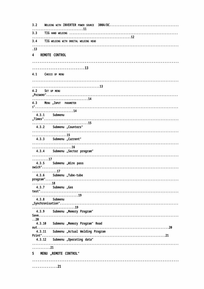
CONTENT
1 TECHNICAL DESCRIPTION ....................................................................................................51.1 TECHNICAL DESCRIPTION OF THE POWER SOURCE ....................................................................................61.2 TECHNICAL DESCRIPTION OF THE IM-99 CONTROL UNIT ............................................................................71.3 TECHNICAL DESCRIPTION OF THE WELDING HEAD T-250 ...........................................................................7
2 OPERATING INSTRUCTION ...................................................................................................8
2.1 INSTRUCTION POWER SOURCE .................................................................................................................92.1.1 Electric mains.............................................................................................................................92.1.2 Gas connection ..........................................................................................................................92.1.3 Ground cable..............................................................................................................................92.1.4 Switching on...............................................................................................................................92.1.5 Torch connection.......................................................................................................................9
3 WELDING ...............................................................................................................................10
3.1 GENERAL REMARKS ..............................................................................................................................103.2 WELDING WITH INVERTER POWER SOURCE 300A/DC.........................................................................113.3 TIG HAND WELDING ..............................................................................................................................123.4 TIG WELDING WITH ORBITAL WELDING HEAD ..........................................................................................13
4 REMOTE CONTROL ..............................................................................................................13
4.1 CHOICE OF MENU ..................................................................................................................................134.2 SET UP MENU „PASSWORD“.................................................................................................................. 144.3 MENU „INPUT PARAMETERS“................................................................................................................ 14
4.3.1 Submenu „Times“....................................................................................................................154.3.2 Submenu „Counters“ ..............................................................................................................154.3.3 Submenu „Current“ .................................................................................................................164.3.4 Submenu „Sector program“ ...................................................................................................174.3.5 Submenu „Wire pass swich“..................................................................................................174.3.6 Submenu „Tube-tube program“.............................................................................................184.3.7 Submenu „Gas test“................................................................................................................194.3.8 Submenu „Synchronisation“..................................................................................................194.3.9 Submenu „Memory Program“ Save.......................................................................................204.3.10 Submenu „Memory Program“ Read out................................................................................204.3.11 Submenu „Actual Welding Program Print“...........................................................................214.3.12 Submenu „Operating data“ ....................................................................................................21
5 MENU „REMOTE CONTROL“ ...............................................................................................21
5.1 ALARM INDICATION ...............................................................................................................................225.2 ADJUSTMENT „MAX- CURRENT“............................................................................................................. 235.3 ADJUSTMENT „ROTATION SPEED“..........................................................................................................235.4 ADJUSTMENT „WIRE SPEED“ ................................................................................................................. 235.5 GENERAL REMARK ................................................................................................................................23
page - 1 -
TEL: +49 2191 463 10 0 * FAX: +49 2191 463 10 11 * e-mail: [email protected]
TECHNODATA GmbH * Leverkuser Straße 65 * D-42897 Remscheid
Description and operating manual TIG orbital welding system IM 99 Version 24 13 a
For Your Safety:
The machines bear the conformity mark - and thus comply with theEC Low Voltage Guideline (73/23/EEC) / EC EMV Directive (89/336/EEC)(The CE Mark is only required in EC member states)In compliance with VDE 0544 (EN 60974-1), the machines can be used in environments withan increased electrical hazard.
Warning: Observe accident prevention regulations!
NOTE: As you operate the IM 99 you have to pay attention to existing appropriate safety
regulations. Once again we point to the regulation that the IM 99 is about to becompletely checked once a year.
Refresher examination on electrical equipment due to VDE 702 / BGV / A3.
IF YOU DON’T PAY ATTENTION THE MANUFACTURER’S GUARAN- TEE WILL BECOME NULL AND VOID!
Use as per regulation:The IM 99 is exclusively to be used in sense of regulation in accordance to usability. (See alsochapter: commissioning.)
Irregular use as per regulation:Dangerous and hazardous situation for human beings, animals and material assets may ocurre ifthe IM 99 is about to be:
Irregular used as per regulation.Used by not trained or supervised personnel.Changed improper or ‘modified’.
Ignoring the following safety procedures can be fatal.Before undertaking welding tasks, put on prescribed dry protective clothing, e.g.
gloves.Protect eyes and face with protective visor.
Electric shocks can be fatalThe machine may only be connected to correctly earthed sockets.

Only operate with intact connection lead including protective conductor and safety plug.
An improperly repaired plug or damaged mains cable insulation can cause electric shocks.
The machine may only be opened by qualified and authorised personnel.Before opening, pull out the mains plug. Switching off is not sufficient. Wait for2 minutes until capacitors are discharged.Always put down welding torch, stick electrode holder in an insulated condition.
page - 2 -
TEL: +49 2191 463 10 0 * FAX: +49 2191 463 10 11 * e-mail: [email protected]
TECHNODATA GmbH * Leverkuser Straße 65 * D-42897 Remscheid
Description and operating manual TIG orbital welding system IM 99 Version 24 13 a
Even touching low voltages can cause you to jump and lead to accidents, so:Secure yourself from falls before working on platforms or scaffolding.When welding, operate handle earth tongs, torch and workpiece properly, not in
ways forWhich they are not intended. Do not touch live parts with bare skin.Only replace electrodes when wearing dry gloves.Never use torches or earth cables with damaged insulation.
Smoke and gases can lead to breathing difficulties and poisoning.Do not breathe in smoke and gases.Ensure that there is sufficient fresh air.Keep solvent vapours away from the arc radiation area. Chlorinated hydrocarbonFumes can be converted into poisonous phosgene by ultraviolet radiation.
Workpiece, flying sparks and droplets are hotKeep children and animals well away from the working area. Their behaviouris unpredictable.Move containers with inflammable or explosive liquids away from the working
area.There is a danger of fire and explosion.Never heat explosive liquids, dust or gases by welding or cutting. There is also a
danger ofexplosions when apparently harmless substances develop high pressures in
enclosedcontainers by heating.
Take care to avoid fire hazardsAny kind of fire hazards must be avoided. Flames can form e.g. when sparks areflying, when parts are glowing or hot slag is present.A constant check must be kept on whether fire hazards have been created in theWorking area.Highly inflammable objects, such as matches and cigarette lighters for example,must not be carried in trouser pockets.You must ensure that fire extinguishing equipment - appropriate to the welding
process - isavailable close to the welding work area and that easy access is possible.
Take care to avoid fire hazardsContainers in which fuels or lubricants have been present must be thoroughlycleaned before welding begins. It is not sufficient simply for the receptacle to be
empty.After a workpiece has been welded, it must only be touched or brought into
contact withinflammable material when it has cooled down sufficiently.Loose welding connections can completely destroy protective conductor systemsof interior installations and cause fires. Before beginning welding work, ensure
that thehandle earth tongs are properly fixed to the workpiece or welding bench and that
there isa direct electrical connection from the workpiece to the power source.
Noise exceeding 70 dBA can cause permanent hearing damageWear suitable earmuffs or plugs.Ensure that other people who spend time in the working area are not
inconveniencedby the noise.
Secure gas cylinder
page - 3 -
TEL: +49 2191 463 10 0 * FAX: +49 2191 463 10 11 * e-mail: [email protected]
TECHNODATA GmbH * Leverkuser Straße 65 * D-42897 Remscheid
Description and operating manual TIG orbital welding system IM 99 Version 24 13 a
Place shielding gas cylinders in the holders provided for them and secure withsafety chains.Take care when handling cylinders; do not throw or heat, guard against themtoppling over.When moving by crane, take off the gas cylinder from the welding machine.
Caution: Interference by electric and electromagnetic fields can be caused by the weldingmachine or by the high-voltage pulses of the ignition unit.
As laid down in Electromagnetic Compatibility Standard EN 50199, the machinesare intended for use in industrial areas; if they are operated e.g. in residentialenvironments problems can occur in ensuring electromagnetic compatibility.The functioning of heart pacemakers can be adversely affected when you arestanding near the welding machine.Malfunctioning of electronic equipment (e.g. EDP, CNC equipment) in the vicinity
of thewelding location is possible.Other mains supply leads, trip leads, signal and telecommunications leads
above,under and near the welding device may be subject to interference.
Warning: Electromagnetic interference must be reduced to such a level that it no longerconstitutes interference.Possible reduction measures:
Welding equipment should be serviced regularly. (see Sect. Maintenance and care)
Welding leads should be as short as possible and run closely together on or near to the
ground.Selective shielding of other leads and equipment in the environment can reduce
radiation.
Caution: Repairs and modifications may only be carried out by authorised, trained,specialist personnel.The warranty becomes null and void in the event of unauthorised interference.Our operating instructions will provide you with an introduction into the safe use of themachine.Therefore please read them closely and only start work when you are familiar with them.
Transport and InstallationThe machines may only be transported and operated in an upright position.Before moving, pull out mains plug and place on the machine.Secure high-pressure shielding gas cylinder with safety chain to prevent it from
topplingover.Do not roll over hoses or cables.
Place the shielding gas cylinder in the cylinder holder and secure it in place with thesecuring chain.Maximum permissible cylinder size at internal pressure:
200 bar, up to 50 l geometrical volume300 bar, up to 33 l geometrical volume
When the current source is moved and positioned, it is only secure against falling to anangle of 15° (as specified in EN 60974-1). Special attention should be paid to the fact that,when the machine is moved, additional danger results from obstacles on the floor as
page - 4 -
TEL: +49 2191 463 10 0 * FAX: +49 2191 463 10 11 * e-mail: [email protected]
TECHNODATA GmbH * Leverkuser Straße 65 * D-42897 Remscheid
Description and operating manual TIG orbital welding system IM 99 Version 24 13 a
these can cause additional tilting moments.
Safety rules for crane transport:Carefully observe the accident prevention regulations VBG 9, VBG 9a and VGB 15.

Lift with the crane at all 4 ring screws simultaneouslyEnsure an even distribution of the load to all four ropes and maintain an angleof at least 60° of the suspension ropesUse only ring chains or suspension ropes of equal length (at least 1 m).Load hooks with securing cleats and skackles of corresponding size to DIN 82 101, Form A.Use minimum rated size 0.4.
Before lifting with a crane, always remove the shielding gas cylinder from the weldingmachine.
Never lift other loads together with the welding machine, e.g. persons, toolboxes,wire spools etc.
Avoid jerks when raising and lowering the welding machine.
Environmental conditions:The welding machine can be operated in a location where there is no risk of explosion at
an ambient temperature of 0°C to +40°C anda relative air humidity up to 50% at 40°C.
where the surrounding air is free of unusual amounts of dust, acids, corrosive gases or
substances etc., insofar as they do not occur during welding.Examples of unusual operating conditions:
Unusual corrosive smoke, vapour, excessive oil vapour, unusual vibrations or jolts, excessivequantities of dust such as grinding dusts etc., severe weather conditions, unusual conditionsnear the coast or on board ship.When installing the machine, ensure a free inlet and outlet of air. The unit is tested toprotection class IP23, i.e.:Protection against penetration of solid foreign bodies Æ > 12mm,Protection against water spray up to an angle of 60° to the vertical.
1 Technical description
The TECHNODATA tube welding equipment IM-99 is the result of many years of experienceconcerning procedures and equipment of orbital TIG-welding systems. High technology, easy
page - 5 -
TEL: +49 2191 463 10 0 * FAX: +49 2191 463 10 11 * e-mail: [email protected]

TECHNODATA GmbH * Leverkuser Straße 65 * D-42897 Remscheid
Description and operating manual TIG orbital welding system IM 99 Version 24 13 a
handling and maintenance, high reliability and flexibility are aims of the development of ourproducts. Easy and fast adjustments on all required welding functions are possible. The equipmentconsists of a welding head and a combined power source with an integrated control unit with a 8-line digital readout enabling a comfortable man-machine usage. The basic design of the weldinghead enables tube to tube sheet weldings from 10 mm to 78 mm internal tube diameter. For largerdiameters the welding head can be equipped with a special extension up to approx. 100 mm tubeI.D. For internal bore welds special torches in various diameters and lengths are available.Weldings can be done also with or without filler wire. The welding head can be equipped with adouble gas shield for covering the entire weld area, such as titanium weldings. Precision groundspindles and centering cartridges guarantee constant and perfect welds, due to the exactcentering. With the three legs support is obtained, that the rotation of the welding head duringwelding process is exactly rectangular to the tube sheet. The three legs can be adjusted in radial,axial or peripheral direction, in order to find the suitable support area between the tubes.
1.1 Technical description of the power source
The power source of the tube to tube sheet welding equipment IM-99 DC has been developed forTIG weldings, manually or mechanized. A mostly advanced 300 A DC inverter power modul is theheart of the power source.The INVERTER power source operates with a frequency of 25 kHz to 60 kHz instead of 50 cycles,common power sources operate with. Firstly the net current becomes equalized and then atransistor alternator with bipolar transistors provides the fequency of 25 - 60 k-cycles. The middle--frequented current now is trasmitted via the transformator of the transistor alternator to thesecondary side. The current transmitted to the secondary side will be equalized and provided forusage.By adding a transistor alternator on the secondary side in FET technology the INVERTER powersource can provide alternating current as well. Most modern microprocessor technolo

gy controlsthe INVERTER power source.
Advantages of INVERTER technology:
• Substantial weight reduction• Substantial reduction of raw material input• High efficiency, low power cost• High cos ϕ• High dynamic control of all parameters• High independence of all parameters from variation of input voltages• Much better welding characteristics, which are favorable when welding "difficult" materials like
titanium, high alloyed steels and aluminum.
Control and adjustment
The control and adjustment of the INVERTER power source is obtained by the microprocessor unit„IM-99" with remote control and 8-line digital readout, keyboard and multi-fold potentiometers.
page - 6 -
TEL: +49 2191 463 10 0 * FAX: +49 2191 463 10 11 * e-mail: [email protected]
TECHNODATA GmbH * Leverkuser Straße 65 * D-42897 Remscheid
Description and operating manual TIG orbital welding system IM 99 Version 24 13 a
Cooling
The power source is equipped with an integrated cooling system.The inverter power part is aircooled.The connected torches are water cooled.
The cooling system consists of:
• cooling-liquid tank• heat exchanger with aircooling• circular piston pump• quick action chucks for hose connections
It provides the necessary cooling of the torches and other parts of the orbital welding heads.
1.2 Technical description of the IM-99 control unit

The control unit IM-99 consists of a microprocessor control system, assembled on a separateboard with all necessary components, incorporated in the power source, having a remote controlwith 8-line display, function keys and potentiometers for high current, rotation speed and wirespeed, which can freely be used at any place just limited by the length of the connecting cable.
The microprocessor system provides a lot of possibilities, to meet the constantly increasingdemands of tube-tube sheet and tube-tube joints. The orbital welding head T-250 for tube-tubesheet weldings as well as the orbital welding head SZ or Z33-36 as well as hand torchesalternatively can be connected to the power source. The control unit automatically indicates thetype of equipment which is connected without any hardware changes. The display with the 8-linereadout, keyboard and the potentiometers has been assembled in robust remote control housing.
Via function keys on the remote control different menues can be selected, shown on the 8-linedisplay, and all parameters can be adjusted according to the requirements, and storedautomatically. The change of the parameters can be done just by inputting new parameters.Selection of the menu "Remote control" enables the start of a welding cycle by using the pushbutton of the welding head or the function keys of the keyboard of the remote control. Thus acomplete welding cycle can be done with the preselected parameters.
1.3 Technical description of the welding head T-250
When designing the following main aspects were taken into consideration:
1. Easy handling
page - 7 -
TEL: +49 2191 463 10 0 * FAX: +49 2191 463 10 11 * e-mail: [email protected]
TECHNODATA GmbH * Leverkuser Straße 65 * D-42897 Remscheid
Description and operating manual TIG orbital welding system IM 99 Version 24 13 a
2. Adaptability to the weld parameters required

3. Exact torch turning control
1. The handling of the welding head is extremely simple. Even unskilled operators will have no
difficulty producing perfect weld - seams. The cartridge is inserted into the tube, the gun is
moved forward until the adjustable legs are touching the tube sheet, the start button is
pressed and the weld cycle starts.
A fully automatic weld procedure now takes place. The torch position can easily be
adjusted with a knurled nut (tubus ring) in axial direction and with an adjusting nut driver in
radial direction. A stable holding device takes care of a trouble free wire feed. Also
changing the tungsten electrode can be executed quickly. Easy handling makes it possible
for the operator to operate two guns at the same time.
2. The tube i.d. ranges from from 10 to 78 mm without any additional equipment. Because of
the adjustable electrode angle fillet weldings up to 45 mm tube internal diameter can be
done. Should larger diameters be required, extensions may be added for up to 100 mm
tube I.D. For internal bore welds special torches in various diameters and lengths will be
manufactured on request. For weldings simultaneously with filler wire a small compact wire
feed unit is attached. This turns with the torch rotation and prevents unregular wire feed
occured by twisting wire. When welding highly oxidizing metals, such as titanium, a front
protection shield is used which gives additional gas coverage. It has clear lenses which
allow the operator to observe the weld as it proceeds.An extra hose for this protection gas is as standard included. The torch is
liquid-cooled, inorder to be able to weld preheated tube sheets up to 250 centigrades. If the
heat is still toohigh, a water cooled protection shield can be assembled in front of the gun.
Examples of joint configurations:

An accurate rotation of the welding head is the result of a cartridge equipped with 2 rows of springloaded balls and a spindle (mandrel) together with a 3 point support of the gun.
2 Operating instruction
page - 8 -
TEL: +49 2191 463 10 0 * FAX: +49 2191 463 10 11 * e-mail: [email protected]
TECHNODATA GmbH * Leverkuser Straße 65 * D-42897 Remscheid
Description and operating manual TIG orbital welding system IM 99 Version 24 13 a
2.1 Instruction power source
Caution !! High tension !! Life danger !!
Note: Any repair work, disasembly of the side covers and cover plates only can be
executed by qualified, authorised people, obbaying the safety regulations.
Removing the covers may cause the loss of any warrenty agreement between
the user and TECHNODATA. The covers only may be removed after at least
two minutes after disconnection with the network.Before connecting the power source to the mains all covers m
ust beassembled.This is not only necessary by safety reasons but also because
of thefunctioning of the cooling systems.
2.1.1 Electric mains
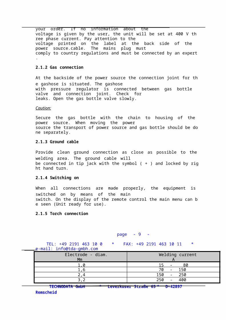
The machine is set in factory at the voltage given with your order. If no information about thevoltage is given by the user, the unit will be set at 400 V three phase current. Pay attention to thevoltage printed on the label at the back side of the power source.cable. The mains plug mustcomply to country regulations and must be connected by an expert.
2.1.2 Gas connection

At the backside of the power source the connection joint for the gashose is situated. The gashosewith pressure regulator is connected between gas bottle valve and connection joint. Check forleaks. Open the gas bottle valve slowly.
Caution:
Secure the gas bottle with the chain to housing of the power source. When moving the powersource the transport of power source and gas bottle should be done separately.
2.1.3 Ground cable
Provide clean ground connection as close as possible to the welding area. The groun
d cable willbe connected in tip jack with the symbol ( + ) and locked by right hand turn.
2.1.4 Switching on
When all connections are made properly, the equipment is switched on by means of the mainswitch. On the display of the remote control the main menu can be seen (Unit ready for use).
2.1.5 Torch connection
page - 9 -
TEL: +49 2191 463 10 0 * FAX: +49 2191 463 10 11 * e-mail: [email protected]
Electrode - diam.Mm
Welding currentA
1,0 15 - 801,6 70 - 1502,4 150 - 2503,2 250 - 400
TECHNODATA GmbH * Leverkuser Straße 65 * D-42897 Remscheid
Description and operating manual TIG orbital welding system IM 99 Version 24 13 a
The hose package of the torch (Welding head T 250 or TIG torch) are connected to the centralconnection with a sleeve nut. The liquid cooling inlet and outlet hoses must be plugged into thecorresponding quick couplings; pay attention to the colour coding.
A. Control cable T-250Connect the plug with the according base plug.

B. Control cable TIG torchConnect the plug with the according base plug.
3 Welding
3.1 General remarks
Automatic switch off
If the power source is started without ingnition the unit will switch off automatically after about 4seconds. Once the arc is interrupted longer than 4 seconds, the unit will swich off as well.
This safety feature is provided in order to avoid• uncontrolled ingnitions• material damages• loss of gas• accidents
Capacity of tungsten electrodes
In spite of these recommendations it is possible to weld most of all materials with electrodediameter 2,4 mms even with lowest current values.When applying the DC welding method, there are used tungsten electrodes with 2 % Thorium (DIN32 528). Thorium-free tungsten electrodes can be used as well.When welding with higher current values the use of gas diffusers may increase the life time of thetorch.Caution: The electrode never should touch the work piece or weld bath. In case this happens,
the electrode must be reground.
Hints for electrode care:
page - 10 -
TEL: +49 2191 463 10 0 * FAX: +49 2191 463 10 11 * e-mail: [email protected]
TECHNODATA GmbH * Leverkuser Straße 65 * D-42897 Remscheid
Description and operating manual TIG orbital welding system IM 99 Version 24 13 a
Always keep the electrode clean. The electrodes have been carefully cleaned by the
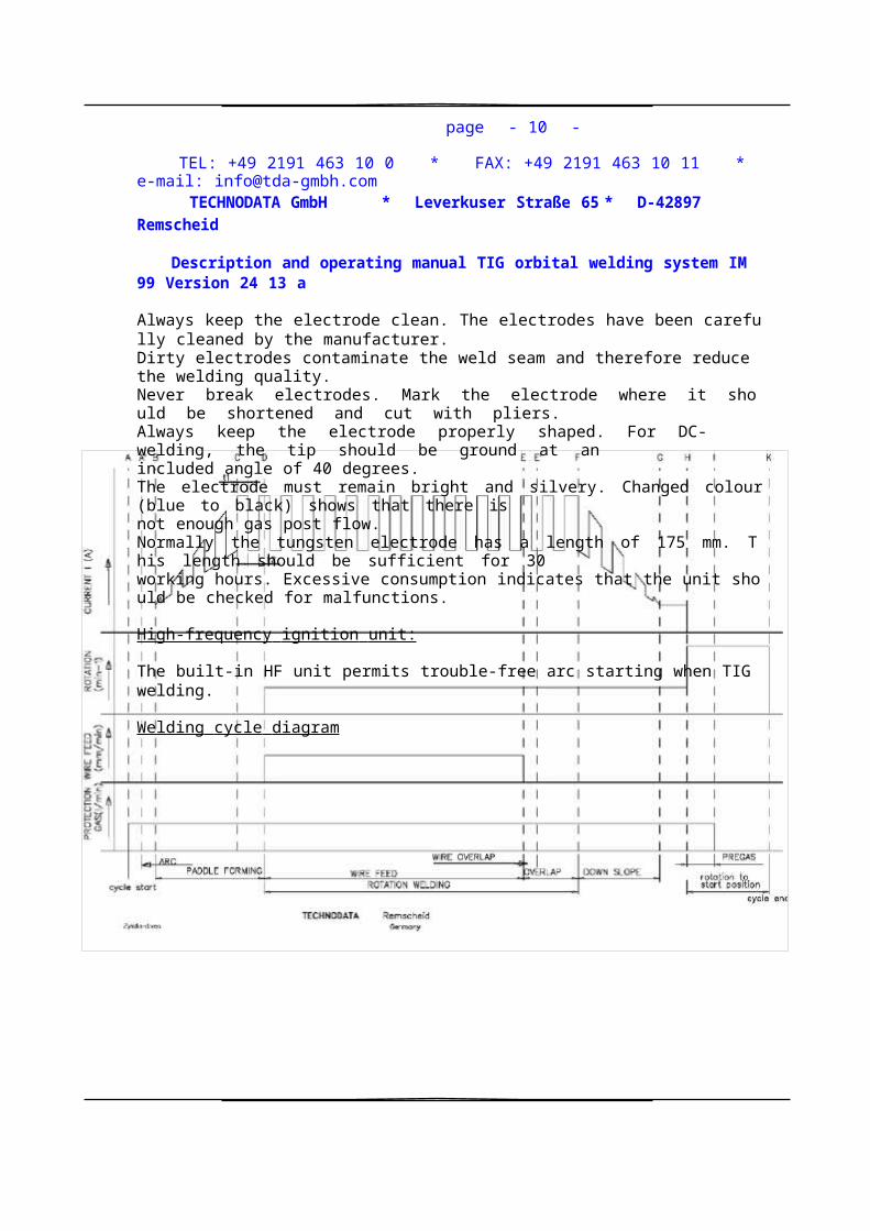
manufacturer.Dirty electrodes contaminate the weld seam and therefore reduce the welding quality.Never break electrodes. Mark the electrode where it should be shortened and cut with pliers.Always keep the electrode properly shaped. For DC-welding, the tip should be ground at anincluded angle of 40 degrees.The electrode must remain bright and silvery. Changed colour (blue to black) shows that there isnot enough gas post flow.Normally the tungsten electrode has a length of 175 mm. This length should be sufficient for 30working hours. Excessive consumption indicates that the unit should be checked for malfunctions.
High-frequency ignition unit:
The built-in HF unit permits trouble-free arc starting when TIG welding.
Welding cycle diagram
3.2 Welding with IM 99
When welding with the IM 99 the complete welding cycle runs off according to the preselectedvalues. All parameters for the connected welding head and the welding itself are put into the

page - 11 -
TEL: +49 2191 463 10 0 * FAX: +49 2191 463 10 11 * e-mail: [email protected]
TECHNODATA GmbH * Leverkuser Straße 65 * D-42897 Remscheid
Description and operating manual TIG orbital welding system IM 99 Version 24 13 a
microprocessor via the keyboard and the multi-fold potentiometers of the remote control. Seediagram on next page.A complete welding cycle for a one-pass TIG welding with filler wire runs off as follows:
A. The welding cycle is started by pushing the start button of the welding head or pushing the
function key "Start/Stop" on the keyboard of the remote control.Protection gas now flows and the distance between tungsten electrode and
workpiecebecomes conductive because of high voltage sparks in this area.
A'. A stable arc now has been established.B. The continuous current increase starts.C. The welding current has reached it pre-selected max. value. The pulsing starts, if selected,
and the paddle forming takes place during the preselected time.D. During the upslope the workpiece becomes heated up continuously in the area of the arc.
A welding bath of sufficient dimension has been obtained and the rotation of the torch can
start as well as the feed of the filler wire.E. The torch completes a circle of 360 degrees. Normally after 360 degrees the filler wire feed
stops.E'. In case filler wire is wanted in the overlap area as well, it can be preselected accordingly.F. After completing the overlap the down-slope starts.G. The welding current will be decreased continuously.H. The arc disappears. The rotation of the torch will be executed with max. speed to the initial
starting point.I. The feed of protection gas stops.K. The starting point is reached, the welding cycle is finished.
An new welding cycle can be started after repositioning of the welding head.
3.3 TIG hand welding
page - 12 -
TEL: +49 2191 463 10 0 * FAX: +49 2191 463 10 11 * e-mail: [email protected]
TECHNODATA GmbH * Leverkuser Straße 65 * D-42897 Remscheid
Description and operating manual TIG orbital welding system IM 99 Version 24 13 a
After connecting the hand torch to the power source at the base plug and connection of the quickaction chucks of the water hoses and the plug of the control cable, the hand torch is ready for useif the power source is swiched on.The hand torch has a "4-function" operation:
1. Push button of torch: = Gas preflow, ignition, initial arc phase
2. Release button of torch: =
Welding with preselected high current or, if
wanted, with pulsing. High/low current3. Push button of hand torch: = Start down-slope, crater filling
4. Release button of hand torch: = end of welding cycle and postgas
Parameter-selection see "function of the keyboard" of the remote control.
300
SIMULATION WIRE SECTOR PULS TUBE-TUBE SYNCHRO SYNCHRO WIRE
PROGRAM PROGRAM PROGRAM PROGRAM ROTATION FILLERWIRE 1;2;1+2pass
START ROTATION WIRE CYCLE
STOP RIGHT FORWARD END F5 F6 F7 F8
7 8 9ABCD
EFGH
IJKL
LIST ACK
4 5 6MNOP QRST UVWX
1 2 3 PREV MAIN
YZ!? C1-C 4 <>()
_ 0+/*= °%#:

Read in and out to the dispay.are able to store (max. capacity 40 program blocs).The actually welding parameters showing in the displaycycle. Printer can be connected as well (option).available for continuous control even during a weldingAn operating time counter as well as a cycle counter isperformed.necessary for a welding cycle - also in simulation - can beCYCLE END; SIMULATION; WIRE ON/OFF; all functionsSTOP; ROTATION RIGHT; WIRE FORWARD;keybard. By using the fuction keys "F7 - F8", and STARTa complete welding cycle can be put in directly via theparameters (dialog-system). All necessary parameters forKeyboard and display enable a "menu-controlled" input of
4 Remote control
3.4 TIG welding with orbital welding headfor tube-tubesheet- or tube-tube-welding connections
After connecting the required orbital welding head to the power source at the base plug andconnection of the quick action chucks of the water hoses with the plug of the control cable, thehead is ready for use if the power source is switched on.
Parameter-selection see "function of the keyboard" of the remote control.
There are 3 Potentiometers for the high current-, rotation speed-, and filler wire speed-adjustment.
4.1 Choice of menu
page - 13 -
TEL: +49 2191 463 10 0 * FAX: +49 2191 463 10 11 * e-mail: [email protected]
TECHNODATA GmbH * Leverkuser Straße 65 * D-42897 Remscheid
Description and operating manual TIG orbital welding system IM 99 Version 24 13 a
After switching on the power source the display shows:
• Input parameters• Remote control
By using the arrow keys below the function keys “F7 - F8“ the required menu can be selected. Thecursor on the left side of the display indicates the selected menu. After pressing the "enter"-key the

selected menu can be seen on the display. Further menues can be selected the same way.
If there is a "+" mark on the right side, this indicates that further lines can be choosen in the displayby using the arrow keys, as the display has only 8 lines.
By pressing the "MAIN" key the start menu will be activated and from there on further menues canbe selected again.By pressing the “PREV“ key the overplaced menu is activated.
4.2 Set up menu „Password“
The menu „ Input Parameters“ can be activated, if the correct password (usually 3 figures) isentered, available for authorised personnel.
When leaving factory the password is "999" but can be changed in the menu "Password" (onlyfigures). For changing the password scroll the cursor down, till the display shows „changepassword 999“ and select your own password and enter.After selection of password and enter the menu " input parameters " is activated. Before this thefollowing menues appear on the display:
• # # # Enter Password for entry menu input parameters
By pressing the "MAIN" key the start menu will be activated and from there on further menues canbe selected again.By pressing the “PREV“ key the overplaced menu is activated.
4.3 Menu „Input parameters“
The input of the 3-digit-password and enter the menu "input parameters“ will appear in the displayand the following menues can be selected:
> Times > Counter > Current> Sector program > Tube-tube program > Wire pass switch> Actual welding progam print > Synchronisation > Program memory> Gas test > Operating data > Monitoring - Current / ARC-Voltage
With the arrow keys the different menues can be selected and activated by pressing "ENTER“.By pressing "MAIN" the start menu will be activated and from there on further menues can beselected again.
page - 14 -
TEL: +49 2191 463 10 0 * FAX: +49 2191 463 10 11 * e-mail: [email protected]
TECHNODATA GmbH * Leverkuser Straße 65 * D-42897 Remscheid
Description and operating manual TIG orbital welding system IM 99 Version 24 13 a
By pressing “PREV“ the overplaced menu is activated.
4.3.1 Submenu „Times“
The following times can be selected or adjusted: (Input in 1 / 10 sec.)
• Pregas• Up-Slope Up slope time from basic current to adjusted high current• Puddleform Arc time from ignition to rotation start• Down-slope Down slope time from high current to basic current• Postgas• Wire backward Time of wire backward moving when welding is finished
For the choice of the next submenu:
• Counters• Current• Sector program
The input of the different times can be realized by pressing the digit keys on the left side of thekeyboard. The units are 1/10 sec.Use the arrow keys for selection of the different times and enter.
The procedure for selection of further menues can be done as already described.
4.3.2 Submenu „Counters“
The following counters can be selected:
• Welding cycle• Endposition• Wire 1. pass• Wire 2. pass
For the choice of the next submenu:
• Set current• Set times• Sector control
The input of the different values can be realized by pressing the digit keys on the left

side of thekeyboard. The number of impulses for 360 angle-degrees are dependend on the type of connectedorbital welding head. (See technical description of the selected welding head).
page - 15 -
TEL: +49 2191 463 10 0 * FAX: +49 2191 463 10 11 * e-mail: [email protected]
TECHNODATA GmbH * Leverkuser Straße 65 * D-42897 Remscheid
Description and operating manual TIG orbital welding system IM 99 Version 24 13 a
Example:
Using the tube-tube sheet welding head T-250 60 impulses represent 360 angle degrees, whichmeans that 1 impulse represents 6 rotation angle degrees.Use the arrow keys for selection of the different counters and quit with "enter".
The welding pass consists of one complete rotation = 360 degrees (60 impulses) plus overlap e.g.61 or 62 impulses (= 366 / 372 rotation angle degrees) for a "one pass" welding cycle.If a "two-pass" welding cycle should be executed the complete welding cycle consists of 120impulses plus overlap = 121 or 122 impulses.During the complete welding pass the selected current values and times are activated, before thedown-slope takes place.
When selecting the parameter "endposition" the following rule must be obbeyed:Should the starting position always be the same (e.g. "10 hours") the head must complete the lastrotation, already started for overlap and down-slope. For an "one-pass" welding the counterconsequently must be set on "120", for a "two-pass" welding on "180".
The counter "Wire 1. pass" usually is set on 60 impulses which means feed of filler wire during onecomplete revolution.The counter "Wire 2. pass" is set on 120 impulses which means feed of filler wire during twocomplete revolutions.
Of course, variations from these values are possible (e.g. 59 or 61 impulses feed of filler wire for a"one-pass" welding or 119 or 121 impulses for a "two-pass" welding).The procedure for selection of further menues can be done as already described.
4.3.3 Submenu „Current“

The following parameters can be selected:• F8 = Pulse-program ‘‘ON / OFF‘‘• # # # A current-min• # # # A current-max• # # # / 100 sec. puls-min• # # # / 100 sec. puls-max
For the choice of the next submenu:• Sector program• Counters• Times
Using the function key "F8" the pulsing can be swichted on or off.The input of the "min-current" values can be realized by pressing the digit keys on the left side ofthe keyboard. The units are "Ampere" (theoretical input option 0 - 300 A).
The input of "max-current" values must be done by means of the multi-fold potentiometer on theremote control, related to "max-current". The variation of values can be seen on the display.
page - 16 -
TEL: +49 2191 463 10 0 * FAX: +49 2191 463 10 11 * e-mail: [email protected]
TECHNODATA GmbH * Leverkuser Straße 65 * D-42897 Remscheid
Description and operating manual TIG orbital welding system IM 99 Version 24 13 a
Important remark: If the "Sector program" (see below) is swiched "on" the input of
max-current only can be realized via the digit keys on the keyboard.
The pulsing times for "max-current" and "min-current" are entered in values of 1/100 sec.
The procedure for selection of further menues can be done as already described.
4.3.4 Submenu „Sector program“
The sector program enables the input of the following parameters in 10 free selective sectors:
• F8 = Sector program "ON / OFF"• Max-current (A) >• Rotation speed (%) > sectors 1-10• Wire speed (%) > free selective• Counter (Sector angle impulses) > 1 impuls = 6 degrees

For the choice of the next submenu:
• Times• Counters• Current
With the function key "F8" the sector program is swiched “ON / OFF“ and is indicated by a LED onthe top of the keyboard. The system enables the splitting of the total welding cycle in 10 freeselective sectors. Within these sectors the following parameters can be selected individually:
• Max-current in Ampere• Rotation speed in percent of max. speed } of the connected• Wire speed in percent of the max. speed } welding head
The input of the values can be realized by pressing the arrow keys on the right side of thekeyboard. Quit with "enter". When the sector control system is swiched "ON",The 3 potentiometers are out of function .
The "welding cycle" preselected in menu "Counters" can be shared into maximum 10 sectors. Aftercounting the preselected impulses, the cycle end program starts. The sum of selected counters inthe sector program must be as high or higher than the preselected welding cycle in menu„Counters“.The procedure for selection of further menues can be done as already described.
4.3.5 Submenu „Wire pass switch“
The following options are given:• Wire 1. pass
page - 17 -
TEL: +49 2191 463 10 0 * FAX: +49 2191 463 10 11 * e-mail: [email protected]
TECHNODATA GmbH * Leverkuser Straße 65 * D-42897 Remscheid
Description and operating manual TIG orbital welding system IM 99 Version 24 13 a
• F7 = Wire 2. pass• F8 = Wire 1. + 2. pass
For the choice of the next menu:• Set times• Set counters• Set current• Sector control

• Tube-tube program• Remote control
The option "wire 1. pass" is selected automatically via the remote control (see menu "remotecontrol" / wire “ON / OFF“ ).
Pressing the function key "F7" provides filler wire feed during the second pass if in menu "remotecontrol" the wire is swiched "ON".
Pressing the function key "F8" provides filler wire during pass one and two, if in menu "remotecontrol" the wire is swiched "ON".
The procedure for selection of further menues can be done as already described.
4.3.6 Submenu „Tube-tube program“
The submenu “tube-tube program“ enables the adjustment of tube-tube welding as follows• F7 = tube-tube program “ON / OFF“• F8 = left with wire “ON / OFF“
# TUBE TUBE PROGRAM• F7 = Automatic right / left “ON / OFF“• F8 = change program start “left / right“
For choice of the next submenu:• Times• Counters• Current
By pressing the function key “F7“ the welding program for tube-tube sheet welding is switched totube-tube welding.This means, the welding head rotation starts anticlockwise until the torch is in startposition. Thenthe welding process is started automatically and the welding head moves clockwise. When thewelding cycle is finished, the welding head is in open position and can be dismounted easily.When the function “F8“ is activated, the program cycle of the tube-tube welding changes! Weldingtakes place during the anticlockwise moving without filler wire feeding. When the first pass isfinished, the welding process is started again and the head moves clockwise (welding with orwithout filler wire).
page - 18 -
TEL: +49 2191 463 10 0 * FAX: +49 2191 463 10 11 * e-mail: [email protected]

TECHNODATA GmbH * Leverkuser Straße 65 * D-42897 Remscheid
Description and operating manual TIG orbital welding system IM 99 Version 24 13 a
By pressing the function key “F6“, the first pass is welded with filler wire.
Attention: The wire nozzle must be adjusted correctly !
The „cycle start“ shows the direction of the welding start (right / left)
If the welding process has to be interrupted (for example in case of emergency of for repair-welds)the welding direction might have to be changed. Press „F5“ to find the correct program start -direction (left = anticlockwise / right = clockwise).
The procedure for selection of further menues can be done as already described.
4.3.7 Submenu „Gas test“
In the submenu “Gas Test“ the following options are offered:• F8 = Gas Test “ON / OFF“
For the choice of the next submenue• Times• Counters• Current• Sector program•While the function „F8“ is activated, gas flow according to the selected quantity is provided. Bychecking the gas flow correct adjustment is possible.
The procedure for selection of further menues can be done as already described.
4.3.8 Submenu „Synchronisation“
The following options are given:• F7 = Synchronisation rotation “ON / OFF“• F8 = Synchronisation wire “ON / OFF“
For the choice of the next menu:• Times• Counters• Current
The use of synchronisation is possible only if the pulsing is in function. With the function key "F7"the synchronisation for rotation can be swiched on or off. During the function "synchronisationrotation" the welding head stops rotation during high current and rotates only during l

ow current.With the function key "F8" the synchronisation for wire can be swiched on or off. During thefunction "synchronisation wire" the filler wire feed takes place only during high current.
page - 19 -
TEL: +49 2191 463 10 0 * FAX: +49 2191 463 10 11 * e-mail: [email protected]
TECHNODATA GmbH * Leverkuser Straße 65 * D-42897 Remscheid
Description and operating manual TIG orbital welding system IM 99 Version 24 13 a
The procedure for selection of further menues can be done as already described.
4.3.9 Submenu „Memory Program“ Save
Select Program No. ( 1 - 40 )
F8 = Save
Order No.: # # # # Tube ##,## x ##,## mms
For the choice of the next menu:• Program read out
For saving a parameter set for a special application select the program no. ( 1 - 40 ), setting thecursor on “program no.“ with the arrow keys and confirm with “enter“.After that the “save“ menue has to be choosen by pressing the function key „F8“The full set of actual parameters are now saved in the selected memory program.It is possible to describe the welding job to be saved by inserting four figures in “order-no.“ and thetube size in “tube“ before saving the parameter set.
The values of the “max. current“, “rotation speed“, and “wire speed“ are saved, when theyare written in the “sector program“
Memory of potentiometer values is not possible !
4.3.10 Submenu „Memory Program“ Read out
Program No. ( 1 – 40 ) ( indicates the last readed out program-no.)Select Program No. ( 1 - 40 )
• F7 = Release read out “On / Off“• F8 + SIMULATION OFF
Read out program• F8 + SIMULATION ON

Print program
For the choice of the next menu:
• Program saveFor welding with memory parameter sets with one of the programs saved before, select theprogram by setting the cursor on “select program no.“, with the arrow keys, put in the programno. …( 1 - 40 ) and confirm with “enter“.
After that the “read out“ menue has to be choosen by pressing the function key „F7“ . The fullparameter set, saved on that program number is now readable by scrolling with the arrow key.
page - 20 -
TEL: +49 2191 463 10 0 * FAX: +49 2191 463 10 11 * e-mail: [email protected]
TECHNODATA GmbH * Leverkuser Straße 65 * D-42897 Remscheid
Description and operating manual TIG orbital welding system IM 99 Version 24 13 a
To activate this parameter set “F8“= Release read out has to be pressed and then “F7“ during thenext 30 seconds.
When “F8“ is pressed “sector program“ is switched on automaticely.
For printing the parameters of the choosen program: Connect the cable of TECHNODATA printerType CBM -910 to the receptacle in front of the remote control housing and connect the printer tomains voltage ( standard AC / 220 V / 1-phase ).
Press function key “F 8“ , and the parameters saved in the choosen program are printed.
4.3.11 Submenu „Actual Welding Program Print“
• F8 = Print
For printing the actual parameters connect the cable of TECHNODATA printer Type CBM -910to the receptacle in front of the remote control housing and connect the printer to mains voltage (standard AC / 220 V / 1-phase ).Press function key “F 8“ , and the actual parameters are printed.
By scrolling the display with the arrow key the full parameter set can be read.

On the print you find date and time of printing, and you have the opportunity to write downadditional informations as Order No., Welders name, Equipment no., Tube size, Tube material,Tube sheet thickness, Tube sheet material, Filler wire ( type and size ), Remarks.
4.3.12 Submenu „Operating data“
This menu shows actual values related to the unit:• Hours• Welding cycles• Welding time (real welding time during cycle)• Cycle time
5 Menu „Remote control“
With the function keys "F7 - F8" the following controls and functions are possible:• = Welding program “Start/Stop“• = Rotation right• = Wire forward
page - 21 -
TEL: +49 2191 463 10 0 * FAX: +49 2191 463 10 11 * e-mail: [email protected]
TECHNODATA GmbH * Leverkuser Straße 65 * D-42897 Remscheid
Description and operating manual TIG orbital welding system IM 99 Version 24 13 a
• = Cycle end• = Simulation “ON / OFF“• = Wire program “ON /OFF“• F7 = Rotation left• F8 = Wire backwards
The function key "Start / Stop" has the same function as the "Start /Emergency stop" button at thehandle of the welding head. Pressing this function key, the welding cycle starts. Pressing the keyduring the welding cycle will interrupt the cycle immediately (without downslope).
In the display the following alarm information can be read:
"Emergency stop activatedPress "F8" for cancellation".

After cancellation the menu "Remote control" is activated and the welding cycle can be startedagain.With the function key "ROTATION RIGHT" the clockwise rotation of the torch can be activated. Therotation will take place as long as the function key is pressed. This enables positioning of the torche.g. for the starting position. If function key "F7" is pressed , the torch rotates anticlockwise.
With the function key "WIRE FORWARD" the wire feed is activated manually as long as the key ispressed. During the wire feed the direction of the wire feed can be checked and adjusted ifnecessary. If function key "F8" is pressed, the wire will be fed back.
Using function key "WIRE ON/OFF" the wire feed during the welding cycle can be swiched "on" or"off". This function can be used even during the welding cycle.
If the function key "SIMULATION ON/OFF" = simulation is activated (ON /OFF), the whole weldingcylcle takes place without arc ignition. This enables to check the rotation speed, the wire quantity,position of torch during cycle and the wire feed. After pressing function key „F5“, the weldingprogram is activated.If the function key "CYCLE END" is activated during a welding cycle the welding stops and thedown slope is started. Using this function, repair weldings can be done (less than a complete cycleof e.g. 366 degrees.)
5.1 Alarm indication
The display shows
"Gas shortage - check gas flow“ or"Water shortage - check water flow".
page - 22 -
TEL: +49 2191 463 10 0 * FAX: +49 2191 463 10 11 * e-mail: [email protected]
TECHNODATA GmbH * Leverkuser Straße 65 * D-42897 Remscheid
Description and operating manual TIG orbital welding system IM 99 Version 24 13

a
After termination of the shortage the alarm can be cancelled by pressing the function key "F8". Thewelding cycle can be started again.
5.2 Adjustment „max- current“
With the Potentiometer on the remote control for "max-current" the max-current can be adjustedstepless. The actual value in Ampere can be seen in menu "set current" !
If the menu "sector parameter" is activated, the function of this potentimeter is swiched off ! (input only by digit
keys)
5.3 Adjustment „rotation speed“
With the Potentiometer on the remote control for "rotation speed" the rotation spe
ed can beadjusted stepless. The value on the potentiometer represents the fraction of 999 which represents100 %. E.G. value one the potentiomer: 450 = 45 % of max. rotation speed.
5.4 Adjustment „wire speed“
With the Potentiometer on the remote control for "wire speed" the wire speed can be adjustedstepless. The value on the potentiometer represents the fraction of 999 which represents 100 %.E.G. value one the potentiomer: 450 = 45 % of max. wire speed (and quantity).
5.5 General remark
Maintenance and careUnder normal operating conditions these welding machines are largely
maintenancefree and require a minimum of care. However, a number of points should be
observedto guarantee fault-free operation of your welding machine. Among these are
regularcleaning and checking, as described below, depending on the level of
contamination inthe environment and the usage time of the welding machine.
Cleaning, testing and repairing of the welding machines may only be carried out bycompetent personnel. In the event of failure to comply with any one of the following teststhe machine must not be operated again until the fault has been rectified.

5.6 CleaningTo do this, carefully disconnect the machine from the mains.PULL OUT THE MAINS PLUG!(Switching off or unscrewing the fuse is not adequate isolation).
Wait for 2 minutes until the capacitors have discharged. Remove the casing cover.The individual components should be handled as follows:
page - 23 -
TEL: +49 2191 463 10 0 * FAX: +49 2191 463 10 11 * e-mail: [email protected]
TECHNODATA GmbH * Leverkuser Straße 65 * D-42897 Remscheid
Description and operating manual TIG orbital welding system IM 99 Version 24 13 a
Current source Depending on the amount of dust, blow out current source using oil- andmoisture-free compressed air.Electronics, circuit boards Do not blow on electronic components or circuit boards with thecompressed air stream but suck clean using a vacuum cleaner.
Repetition test according to VDE 0702 and VBG 15
Test sequence:Quarterly test: 1. Visual check of correct condition
2. Measurement of protective conductor resistanceAnnual test: 1. Visual check of correct condition
2. Measurement of protective conductor resistance3. Measurement of insulation resistance following internal
cleaning of the power source4. Measurement of open circuit voltage5. Function test of the welding machine
Visual check of correct condition
The machine must be inspected for externally visible faults (without opening the machine). Duringthis inspection, attention must be paid, for example, to the following points:External faults in mains plug and mains cable, e.g. insulation faults, scorch or pressure marks.Defects in anti-kink protection and the strain relief of the connection lead, mains switch.Faults in welding leads, tube package, plug fixture, arc torch.Signs of an overload and improper use.Damage to stop points and casing.Improper interference and modifications.The type plate and warning symbol must be present and legible.
Repair work
Repair and maintenance work may only be performed by specialist staff. In all service matters,

always consult your dealer. Return deliveries of defective equipment subject to warranty may onlybe made through your dealer. When replacing parts, use only original spare parts.When ordering spare parts, the machine type, serial number and item number of the machine, aswell as the type description and item number of the spare part must be quoted.
If repair or maintenance work is carried out on this machineby personnel who are not trained and authorised to undertake such work,
the right to claim under the warranty lapses.Description to find source of error by the Orbital welding equipment, Type IM-99
Remove of casing sheets and casing cover ! The equipment should be complete ready to use.Be careful by switch on the equipment because it is under power !!!Switch on the main switch only – without starting a cycle.
CARD TRDC2 ( right side – middle )
page - 24 -
TEL: +49 2191 463 10 0 * FAX: +49 2191 463 10 11 * e-mail: [email protected]
TECHNODATA GmbH * Leverkuser Straße 65 * D-42897 Remscheid
Description and operating manual TIG orbital welding system IM 99 Version 24 13 a
LED red +5V / +15V / -15V lights on when the equipment was startedLED STOER dark, light on by an error ( main error )LED IPRUE dark, light on by error primary over currentLED PRUE dark, light on by error primary over voltageLED PRUN dark, light on by error primary under voltageLED TEMP dark, light on by overheating of InverterLED RGLSPR dark, light on by an externally governor stop was installedAt the terminal gib X2/15 and X2/8 are 10V/DC
CARD SPW2 ( left side - middle )
LED1 red must be on always if the equipment was started.At the terminal gib X4/1 and X4/2 are 16V/AC .
CARD DW 7,5 ( left side – middle )
At the terminal L1, L2, L3 are the main current 3 x 400V/AC.
Transformer ( right side - down )
Secondary voltage 42V/AC
Transformer 1-A2 ( up )
Secondary voltage 24V/DC, green LED must be shining.

CARD WK3 ( right side - down )
LED2 dark, light on - fuse F 2 ( water pump ) is damaged.LED1 dark, light on - fuse F 1 ( ignition unit and gas valve ) is damaged and one of them
is activated.
CARD 1-A1 ( up )
At the terminal L and N - main current 30V/ACLED Power and RUN green lights on if the equipment was started
LED red input signs
X0 dark light on, if the start bottom at the welding head is pressingX1 dark or light on dependent on the position of the micro switch in the welding head
page - 25 -
TEL: +49 2191 463 10 0 * FAX: +49 2191 463 10 11 * e-mail: [email protected]
TECHNODATA GmbH * Leverkuser Straße 65 * D-42897 Remscheid
Description and operating manual TIG orbital welding system IM 99 Version 24 13 a
X2 dark light on, if the welding current is flowing)X3 light on dark, if gas is missing or flow control is damagedX4 light on dark, if water pump, flow control or fuses F2 on WK3 are damagedX5 dark ( free )X6 light on dark, bridge G to I in the 14-pole-plug of the hose ( welding head ) is
missingX7 dark light on if the start bottom at the hand torch is be pressed
LED red output signs
Y0 – Y 7 dark
Analog Module 1-A1/K0 – K2
LED red 24V and A-D resp. D-A lights must be on if the equipment was started
Starting the welding cycle !
CARD TRI 1 resp. 4 ( left side - middle )
LED red 1 and 2 lights on if the equipment was startedoutput Y1 of SPS 1-A1 light on if no welding current is flowing too
CARD TRDC2 ( right side - middle )
LED STR/STP light on if the equipment was startedlight on if no welding current is flowing too
LED IGRO light on if welding current is flowing
!! ATTENTION : main switch of power source on OFF and pull the current cable out of th e plug
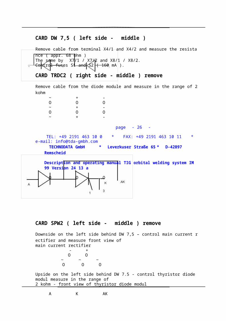
CARD DW 7,5 ( left side - middle )
Remove cable from terminal X4/1 and X4/2 and measure the resistance ( appr. 68 ohm )The same by X7/1 / X7/2 and X8/1 / X8/2.Control fuses S1 and S2 ( 160 mA ).
CARD TRDC2 ( right side - middle ) remove
Remove cable from the diode module and measure in the range of 2 kohm~ + -O O O~ + -O O O~ + -
page - 26 -
TEL: +49 2191 463 10 0 * FAX: +49 2191 463 10 11 * e-mail: [email protected]
TECHNODATA GmbH * Leverkuser Straße 65 * D-42897 Remscheid
Description and operating manual TIG orbital welding system IM 99 Version 24 13 a
O O O
CARD SPW2 ( left side - middle ) remove
Downside on the left side behind DW 7,5 – control main current rectifier and measure front view of
main current rectifier- +
O O~ ~ ~O O O
Upside on the left side behind DW 7.5 - control thyristor diode modul measure in the range of2 kohm - front view of thyristor diode modul
A K AKO O O
CARD TRI 1 resp. 4 ( left side - middle ) - removeupside primary switch PLUS U3downside primary switch MINUS U4measure in the range of 2 kohm
primary switch PLUS U3
O OO
page - 27 -
TEL: +49 2191 463 10 0 * FAX: +49 2191 463 10 11 * e-mail: [email protected]
TECHNODATA GmbH * Leverkuser Straße 65 * D-42897 Remscheid
Description and operating manual TIG orbital welding system IM 99 Version 24 13 a
OO
primary switch MINUS U4
O OO

OO
Wiring SPW2 / TRI1/4 and DW 7,5
SPW2 terminal X2/1 TRI1 terminal X2/1SPW2 terminal X2/2 TRI1 terminal X2/2
SPW2 terminal X1/1 DW7,5 terminal X9/1SPW2 terminal X1/2 DW7,5 terminal X9/2
SPW2 terminal X4/1 DW7,5 terminal X3/1SPW2 Klemme X4/2 DW7,5 terminal X3/2
SPW2 terminal X5/1 thyristor modul connection upside ( 1 )SPW2 terminal X5/2 thyristor modul connection middle U2 ( K ).
Technical changes, up-dates, modifications and change of industrial designs prior to any
announcement.
* * * * * *
page - 28 -
TEL: +49 2191 463 10 0 * FAX: +49 2191 463 10 11 * e-mail: [email protected]

TIG 300 DC
5011a
12.2000
241303-A.vec
Orbital-welding system IM 99Power source TIG 300 DC
Design / Front view
Vers.: 24 13 24 13 03 - A 24 13 04
Inverter TIG 300 DC
Kunde: TECHNODATA
DatumBea
rb.
Ges
p.
12.2000
R.Kia
ups
241303
-B.vec
Kom.-Nr.:Remscheid
Germany
Type: Orbital-Rohreinschweißanlage
Orbital-welding systemIM 99
( Stromquelle / Power source )Baugruppe:Aufbau / Design / Side view
Vers.: 24 13 Zg.-Nr.:
24 13 03 - B 24 13
04
Unit= 0.4 Blatt: 02
1716

Zus
atzg
as
Ch
amb
erg
as
12.2000
241303-C.vec
Orbital-welding system IM 99Powersource TIG 300 DC
Desig
n-plan
Vers.: 24 13 24 13 03 - C 24 13 04
230V~
230V
Zusatzgas
P3
Chamber gas
17
230V
230V
FX2N - 16 MR
Mini-DIN 8-pos
Male
Y 7Y 7

Kunde: TECHNODATA
X2/16
DatumBea
rb.
Ges
p.
12.2000
R.Kia
ups
241302
-B.vec
Kom.-Nr.:Remscheid
Germany
Type: Orbital-Rohreinschweißanlage Typ IM 99
Orbital-welding system Vers.: 24 13
Power source TIG 300 DCBaugruppe:Steuerung / Control system
Zg.-Nr.: 24 13 02 - B 24 13 04
Software: Wick 01
Unit= 1.6 Bl
att: 02
1-A1/K1
FX2N-4AD FX2N-4DA
CH3CH4
V - V - V - V -
8

WIRE SECTOR12.2000
241302-C.vec
Orbital-Rohreinschweißanlage Vers.: 24 13Orbital-welding system IM 99Power source TIG 300 DC
Control system
24 13 02 - C 24 13 04
Remote control E 300
( rear view )
SIMULATION
PROGRAM
PROGRAM
TUBE-TUBE
HEAD 1 HEAD 2PROGRAM PROGRAM
WIRE
1;2;1+2 pass
STARTROTATION
RIGHT
WIREFORWARD
CYCLEEND F5 F6 F7 F8
89ABCDEFGHIJKL
5
6MNOPQRSTUVWX
LIST ACK
grün
rot
blau
weiß
1 2 3YZ!? C1-C4 <> ()
_0
+/*= °%#:
PREV MAIN
Max. CurrentRotationFiller wire
schwarz

12.2000
241302-D.vec
Orbital-RohreinschweißanlageOrbital-welding system IM 99Power source TIG 300 DC
Control system
Vers.: 24 13 24 13 02 - D 24 13 04
17.
1
7
130 13340 73 80 90
26 25 24 15 16 45 14 36 34 12 109 1318111 6 7 64 33 8 35 3710 70 7172 79 74 75 76 7783 85 93 91 96 99 98103108 51
52662223
21
20
43,44
53
54
100
10559
104
107
106
58
4.1 4.2 38
1
3
5.1 5.2 50 62 97 87 88 9239
27 28 4860 61 9 11 42 41 31 3229 49
30
17.126 25 2451
52662223
21
20
43,44
53
54
100
59
58

5153
52
54
58
31 03 - 00a
3103-00a.vec Glocke / Brennereinheit
8385
9699
98
86
84
90
89
78, 82
76
97
80
79
77
108
105
103
104
107
106
838892
94 95

12084 101
03.2000 31 03 - 00B
3103-00B.vec 1.6
TUBE WELDING and TUBE EXPANDING
for HEAT EXCHANGER- and BOILER MANUFACTURES
d
d. Jul.12.2004
PARTSLIST page:
orbital welding head type T-250version 31.03
POS. LABEL ITEM NUMBER
01
17928800102
17928800203
17928800304/1
179288004/104/2
179288004/205/3
179288005/305/4
179288005/406
17928800607 17928800708 17928800809 17928800910 17928801011 17928801112 17928801213 17928801314 17928801415 17928801516 17928801617 179288017/117a 179288017/218 17928801819 17928801920 17928802021 17928802122 17928802223 17928802324 17928802425 17928802526 17928802627 17928802728 179288028
29
179288029
30
179288030
31
179288031
32
179288032
33
179288033
34
179288034

35
17928803536
17928803637
17928803738
17928803839
179288039
DESCRIPTION
main -shaftcentering supportflangerotor current couplingstator current couplinginsulating flage statorinsulating piece rotorconnecting ringstator gas water couplingbearing blockfeeder blockcrown wheelcrown wheeltubus bearing ringtubus setting ringtubus glyding ringtubus conter ringtubus base ringpoint piece for basing legbasing leg of 3 portshousing central bodyhousing captorchtorch holdertorch slidecollet for torchinsulating piece for torch slideBase block for torch holdertorch slide holderConnecting platefitting for gas-water returnfitting for water preflowfitting for water preflowrotation-motorhandlesuspensionballer bearing frontballer bearing back sidesnap ring front sidesnap ring back sidepush buttom start stopprotection for push buttom
QUANTITY
1,001,001,001,001,001,001,001,001,001,001,001,001,001,001,001,001,001,003,003,001,001,001,001,001,001,001,001,001,001,002,001,001,001,001,001,001,001,001,001,001,001,00
TEL.: +49 2191 463 10 0 FAX: +49 2191 463 10 11 E-MAIL: [email protected]
TUBE WELDING and TUBE EXPANDING
for HEAT EXCHANGER- and BOILER MANUFACTURES

d
d. Jul.12.2004
PARTSLIST page:
orbital welding head type T-250version 31.03
POS. LABEL ITEM NUMBER
40
17928804041
12952033242
17928804243
12927430744
12927402348
17928804849
17928804950
17928805051
17928805152
17928805253
17928805354
17928805458
12928020459
129274043
60 129274043 DESCRIPTION
pinmicro switch for orbital welding headholder for micro switchclamping sleeveinsulating sealnut for fittingnut for fittinghold down nutclamping piece wire guide supportpin for wire guide supportinsulating sleeveclamping piece for wire giude nozzlewire guide nozzleviton hoseviton hose

QUANTITY
2,001,001,001,00
1,002,001,00
12,001,00
1,001,001,001,003,003,00
61 179560616 1,0062
17928806264
17928806470
17928807071
17928807172
17928807274
17928807475
17928807576
17928807677
17928807778
17928807879
17928807980
17928808082
17928808283
17928808384
17928808485
17928808586 17928808687 17928808788 17928808889 17928808990 17928809091 17928809192 17928809293 17928809394 17928809495 179288095
flange for motor rotationseal ( quad ring )block for carbon supportcarbon guidecarbon brushessupport for wire protectorwire protectorshaft for wire unitflange for slip ringsocketslip ringslip ringsockethousing for wire feedercap of housing for wire feedershaft for wire feedershaft for wire feedercrown wheel for wire feedercrown wheel wire feed motorwire feeder rollershaftdistance ringbase

flange for wire feed motorballer bearingbase flange for spool holderwire feed motor
1,005,001,002,002,001,001,001,001,001,001,001,001,00
1,001,001,001,001,001,002,001,001,001,002,001,001,00
TEL.: +49 2191 463 10 0 FAX: +49 2191 463 10 11 E-MAIL: [email protected]
TUBE WELDING and TUBE EXPANDING
for HEAT EXCHANGER- and BOILER MANUFACTURES
d
d. Jul.12.2004
PARTSLIST page:
orbital welding head type T-250version 31.03
POS. LABEL ITEM NUMBER
96
17928809697
17928809798
17928809899
129274041100
129274041101
179288101103
179288103104
179288104105 179288105106 179288106107 179288107108 179288108109 179288109110 179288110111 179288111113 179288113114 179288114115 179288115120 179288120122 179288122127 179288127129 129274304130 179288130133 179288133136 179288136
DESCRIPTION
wire nozzlewire nozzlewire nozzle for wire guide hosewire feeding hosewire feeding hosescrewspool hoderspringconter nutfriction platewasher for springnutsnap ringGuide pinBaller spring screwballer bearingsnap ring

screwballer bearingcurrent cablescrewceramic nozzle size 6needle bearingheadless screw M3 x 8headless screw M3 x 8
QUANTITY
1,001,001,001,001,001,001,001,001,001,001,001,00
1,001,001,001,001,002,002,001,001,001,001,001,001,00
TEL.: +49 2191 463 10 0 FAX: +49 2191 463 10 11 E-MAIL: [email protected]