solar power mobile charger using buck converter · 2. solar energy comes in free of charge. the...
TRANSCRIPT

Solar Power Mobile Charger Using Buck
Converter
A Project report submitted in partial fulfilment
of the requirements for the degree of B. Tech in Electrical Engineering
By
Adarsha Rana (11701615002)
Sujan Gian (11701615060)
Manish Kumar (11701615019) .........................................................
...........................................................
Under the supervision of
Mr. Subhasis Bandopadhyay
Assistant Professor Dept. of Electrical Engineering
Department of Electrical Engineering
RCC INSTITUTE OF INFORMATION TECHNOLOGY
CANAL SOUTH ROAD, BELIAGHATA, KOLKATA – 700015, WEST BENGAL
Maulana Abul Kalam Azad University of Technology (MAKAUT) © 2018
: Table of Contents :
Page No.
1. Certificate
2. Acknowledgement
3 Abstract 1
CHAPTER 1: ENABLING TECHNOLIGIES FOR SOLAR POWER MOBILE
CHARGER USING BUCK CONVERTER
1.1 INTRODUCTION 2
1.2 PURPOSE OF THIS PROJECT 3
1.3 PHOTOVOLTAIC CELL 4
1.4 SOLAR PROCESS 6
1.5 ADVANTAGES OF SOLAR POWER 7
CHAPTER 2: BLOCK DIAGRAM
2.1 BLOCK DIAGRAM OF THE SYSTEM 8
CHAPTER 3: PROPOSED SYSTEM HARDWARE AND ARCHITECTURE
3.1 LIST OF HARDWARE 9
3.2 DC-DC BUCK CONVERTER 10
3.3 SOLAR PANEL 12
3.4 LITHIUM BATTERY 14
3.5 DC VOLTMETER 16
CHAPTER 4: Mathematical Model
4.1 MATHEMATICAL MODEL OF BUCK 17
CONVERTER WORKIG
Page No.
CHAPTER 5: SYSTEM IMPLIMENTATION
5.1 STEMATIC DIAGRAM 18
5.2 OVSERVATION AND RESULT 19
CHAPTER 6: CONCLUSION AND FUTURE WORK
6.1 CONCLUSION 21
6.2 FUTURE SCOPE AND APPLICATION 21
REFARENCE 22
List Of tables Page No.
Table 1 – Time required charging a battery 20
Table 2 – Voltage across solar panel 21
List of figure Page No.
Fig. 1 - Solar Cell 5
Fig. 2 - Solar Process 6
Fig. 3 - Block diagram of solar powered mobile charger 8
Fig. 4 - LM2596 dc-dc buck converter 12
Fig. 5 – Circuit diagram of LM2596 dc-dc buck converter 12
Fig. 6 – Solar Panel 14
Fig. 7 - Structure of a Li-ion battery cell 16
Fig. 8 – Lithium Battery 16
Fig. 9 – DC VOLTMETER 17
Fig. 10– Schematic of working of buck converter 18
Fig.11 – Schematic diagram of the system 19
Fig. 12 - Circuit diagram of LM2596 dc-dc buck converter 19
Fig. 13 - Voltage vs time of day 20
Fig. 14 - Hardware implementation of the device 21

Department of Electrical Engineering RCC INSTITUTE OF INFORMATION TECHNOLOGY
GROUND FLOOR, NEW BUILDING, CANAL SOUTH ROAD, BELIAGHATA, KOLKATA – 700015, WEST BENGAL
CERTIFICATE
To whom it may concern
This is to certify that the project work entitled Solar Power Mobile Charger Using
Buck Converter is the bona fide work carried out by Sujan Gain (11701615060),
Adarsha Rana (11701615002),Manish Kumar (11701615019) , a student of
B.Tech in the Dept. of Electrical Engineering, RCC Institute of Information
Technology (RCCIIT), Canal South Road, Beliaghata, Kolkata-700015, affiliated to
Maulana Abul Kalam Azad University of Technology (MAKAUT), West Bengal,
India, during the academic year 2018-19, in partial fulfillment of the requirements
for the degree of Bachelor of Technology in Electrical Engineering and that this
project has not submitted previously for the award of any other degree, diploma
and fellowship.
_____________________ ________________________
Signature of the Guide Signature of the HOD
Name: Name:
Designation Designation
___________________________
Signature of the External Examiner
Name:
Designation:

ACKNOWLEDGEMENT
It is my great fortune that I have got opportunity to carry out this project work under the
supervision of Mr. Subhasis Bandopadhyay assistant professor in the Department of
Electrical Engineering, RCC Institute of Information Technology (RCCIIT), Canal South
Road, Beliaghata, Kolkata-700015, affiliated to Maulana Abul Kalam Azad University
of Technology (MAKAUT), West Bengal, India. I express my sincere thanks and deepest
sense of gratitude to my guide for his constant support, unparalleled guidance and limitless
encouragement.
I wish to convey my gratitude to Prof. (Dr.) Debasish Mondal, HOD, Department of
Electrical Engineering, RCCIIT and to the authority of RCCIIT for providing all kinds of
infrastructural facility towards the research work.
I would also like to convey my gratitude to all the faculty members and staffs of the
Department of Electrical Engineering, RCCIIT for their whole hearted cooperation to make
this work turn into reality.
-----------------------------------------------
Full Signature of the Student
Place:
Date:
ABSTRACT
In almost all the countries mobile phones is the most popular form of communication. The
number of mobile users will surpass 7.6 billion this year (2018) and the number is growing
as technology is getting better and the cost of production also lowers. However it becomes
very inconvenient for persons occupied with work or travelling long distances as the average
lifetime of a mobile phone battery is less than 10 hours. Solar phone chargers use small
solar panel to absorb light. This process still forces customers to carry another device along
with their cell phone. And also the proposed system, solar powered charger (SPC) plays an
important role in mobile charging during travelling. The sun is the ultimate power source
and solar energy is renewable energy source. The SPC system is ecofriendly and user
friendly. The solar panel used is of 10v rating. The voltage must be suitably step down. So
we designed a small charger panel, getting the appropriate voltage and power output
through a DC-DC step-down buck converter. We designed a final prototype that should be
able to charge any of the commonly used local phones in 10-12 hours of direct sunlight.
1
CHAPTER 1: ENABLING TECHNOLIGIES FOR SOLAR POWER MOBILE CHARGER
USING BUCK CONVERTER
1.1 INTRODUCTION
Solar energy is the energy produced directly by the sun and collected elsewhere, normally
the Earth. The sun creates its energy through a thermonuclear process. The process creates
heat and electromagnetic radiation.
Only a very small fraction of the total radiation produced reaches the Earth. The radiation
that does reaches the Earth is the indirect source of nearly every type of energy used today.
The radiation that does reach the Earth is the indirect source of nearly every type of energy
used today. The exceptions are geothermal energy, and nuclear fission and fusion. Even
fossil fuels owe their origins to the sun; they were once living plants and animals whose life
was dependent upon the sun.
Much of the world's required energy can be supplied directly by solar power. More still can
be provided indirectly. The practicality of doing so will be examined, as well as the benefits
and drawbacks. In addition, the uses solar energy is currently applied to will be noted.
Due to the nature of solar energy, two components are required to have a functional solar
energy generator. These two components are a collector and a storage unit. The collector
simply collects the radiation that falls on it and converts a fraction of it to other forms of
energy (either electricity and heat or heat alone). The storage unit is required because of
the non-constant nature of solar energy; at certain times only a very small amount of
radiation will be received. At night or during heavy cloud cover, for example, the amount of
energy produced by the collector will be quite small. The storage unit can hold the excess
energy produced during the periods of maximum productivity, and release it when the
productivity drops. In practice, a backup power supply is usually added, too, for the
situations when the amount of energy required is greater than both what is being produced
and what is stored in the container.
2

1.2 PURPOSE OF THIS PROJECT
Our main purposes of this project are mentioned bellow –
1. There are some remote areas of India that have not yet reached the electrification.
In these remote areas using this solar power mobile charger, people can charge
mobile phones and some USB devices effortlessly and without the use of electricity.
2. Solar energy comes in free of charge. The energy from the sun is free. The source of
energy is practically free because we get sunlight directly from sun.
3. Solar Energy is an Eco friendly and renewable energy. So it does not have any natural
pollution.
4. Its cost is less and once it is installed, it offers a lot of benefits.
5. The cost of maintenance is very few.
6. By the store of this energy in batteries and we will be able to run different USB
devices (like USB fan, USB light etc.) later on.
7. It also helps reduces cost such as electric bills as the solar charger source of energy is
free.
8. The solar charger also operates quietly and this does not contribute to noise
pollution.
3

1.3 PHOTOVOLTAIC CELL
The term "photovoltaic" comes from the Greek (photo) means "light", and "voltaic",
means electric ,from the name of the Italian physicist “VOLTA "after whom a unit of
electro-motive force, the volt is named. The sun is a star made up of hydrogen and
helium gas and it radiates an enormous amount of energy every second. A photovoltaic
cell is an electrical device that converts the energy of light directly into electricity by
photovoltaic effect. Photovoltaic is the field of technology and research related to the
practical application of photovoltaic cells in producing electricity from light, though it is
often used specifically to refer to the generation of electricity from sunlight. Cells can be
described as photovoltaic even when the light source is not necessarily sunlight
(lamplight, artificial light, etc.). In such cases the cell is sometimes used as a photo
detector (for example infrared detectors, detecting light or other electromagnetic
radiation near the visible range, or measuring light intensity. The operation of a
photovoltaic (PV) cell requires 3 basic attributes:
The absorption of light, generating either electron-hole pairs or exactions.
The separation of charge carriers of opposite types.
The separate extraction of those carriers to an external circuit.
In contrast, a solar thermal collector collects heat by absorbing sunlight, for the purpose
of either direct heating or indirect electrical power generation. "Photo electrolytic cell"
(photo electrochemical cell), on the other hand, refers either a type of photovoltaic cell
(like that developed by A.E. Becquerel and modern dye-sensitized solar cells or a device
that splits water directly into hydrogen and oxygen using only solar illumination.
Photovoltaic power generation employs solar panels composed of a number of solar
cells containing a photovoltaic material.
Materials presently used for photovoltaic include monocrystalline silicon,
polycrystalline silicon, amorphous silicon, cadmium telluride, and copper indium
gallium selenite/sulphide. Due to the increased demand for renewable energy sources,
the manufacturing of solar cells and photovoltaic arrays has advanced considerably in
recent years. 4

Solar photovoltaic are a sustainable energy source. By the end of 2011, a total of 71.1
GW had been installed, sufficient to generate 85 TWh/year. And by end of 2012, the 100
GW installed capacity milestone was achieved.
Solar photovoltaic is now, after hydro and wind power, the third most important
renewable energy source in terms of globally installed capacity. More than 100
countries use solar PV. Installations may be ground-mounted (and sometimes
integrated with farming and grazing) or built into the roof or walls of a building (either
building-integrated photovoltaic or simply rooftop).
Driven by advances in technology and increases in manufacturing scale and
sophistication, the cost of photovoltaic has declined steadily since the first solar cells
were manufactured, and the liveliest cost of electricity (LCOE) from PV is competitive
with conventional electricity sources in an expanding list of geographic regions. Net
metering and financial incentives, such as preferential feed-in tariffs for solar-generated
electricity, have supported solar PV installations in many countries. With current
technology, photovoltaic recoup the energy needed to manufacture them in 3 to 4 years.
Anticipated technology would reduce time needed to recoup the energy to 1 to 2 year.
Fig. 1 - Solar Cell
5

1.4 SOLAR PROCESS
Photovoltaic cells are made of special materials called semiconductors such as silicon.
An atom of silicon has 14 electrons, arranged in three different shells.
The outer shell has 4 electrons. Therefore a silicon atom will always look for ways to fill
up its last shell, and to do this, it will share electrons with four nearby atoms. Now we
use phosphorus (with 5 electrons in its outer shell). Therefore when it combines with
silicon, one electron remains free.
When energy is added to pure silicon it can cause a few electrons to break free of their
bonds and leave their atoms. These are called free carriers, which move randomly
around the crystalline lattice looking for holes to fall into and carrying an electrical
current.
However, there are so few, that they aren't very useful. But our impure silicon with
phosphorous atoms takes a lot less energy to knock loose one of our "extra“ electrons
because they aren't tied up in a bond with any neighbouring atoms. As a result, we have
a lot more free carriers than we would have in pure silicon to become N-type silicon.
The other part of a solar cell is doped with the element boron(with 3 electrons in its
outer shell)to become P-type silicon.
Now, when this two type of silicon interact, an electric field forms at the junction which
prevents more electrons to move to P-side.
When photon hits solar cell, its energy breaks apart electron-hole pairs. Each photon
with enough energy will normally free exactly one electron, resulting in a free hole as
well. If this happens close enough to the electric field, this causes disruption of electrical
neutrality, and if we provide an external current path, electrons will flow through the P
side to unite with holes that the electric field sent there, doing work for us along the
way. The electron flow provides the current, and the cell's electric field causes a voltage.
Fig. 2 - Solar Process 6
1.5 ADVANTAGES OF SOLAR POWER
It is estimated that in 2025, of the total world’s power generation, 10% will be by solar
power. The solar power is free, the sun will be shining as long as the human race is around.
In one hour more sunlight falls on the earth than what is needed by the entire population in
one year. So this energy needs to be harvested. The potential for the solar energy industry is
huge. As more and more people begin to realize the great benefits of solar power
generation, they will start to shift towards using it. Solar panels have relatively long life
spans of 30-40 years and rarely need to be replaced for being faulty. They also produce as
much energy over their lifetime as nuclear fuel rods without hurting the environment. Solar
panels work with no moving parts which results in silence as well as a miniscule requirement
for maintenance. The energy from the sun can be converted into AC power to charge
devices, can be stored in batteries.
Solar energy is a renewable energy sources.
Solar energy comes in free of charge.
Solar cells panel on the solar charger does not require much maintenance.
It also helps reduces cost such as electric bills as the solar charger source of energy is
free.
7
CHAPTER 2: BLOCK DIAGRAM
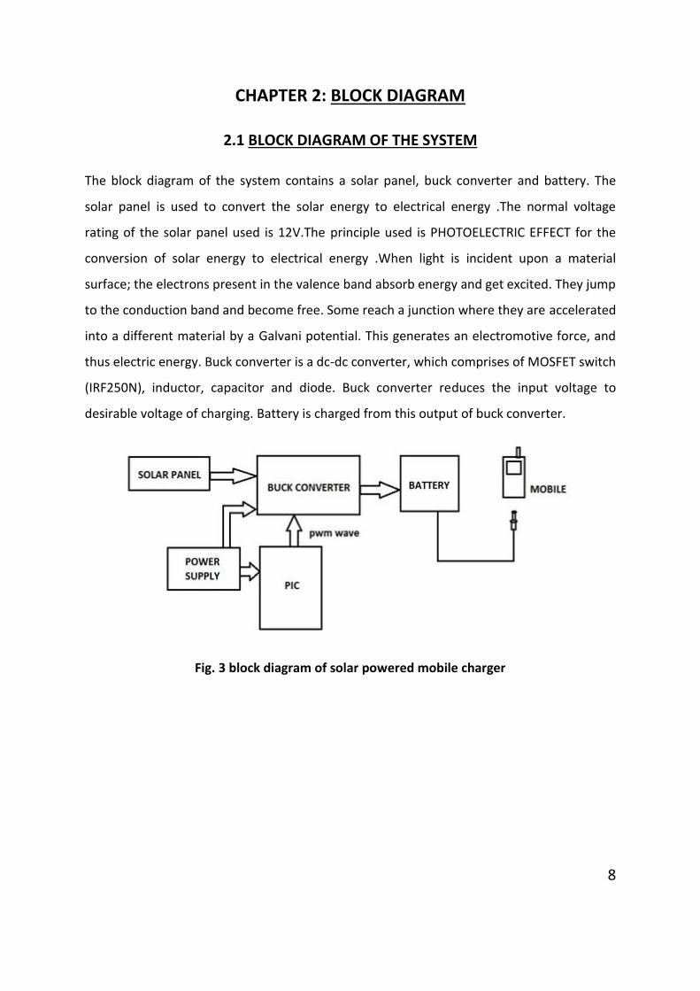
2.1 BLOCK DIAGRAM OF THE SYSTEM
The block diagram of the system contains a solar panel, buck converter and battery. The
solar panel is used to convert the solar energy to electrical energy .The normal voltage
rating of the solar panel used is 12V.The principle used is PHOTOELECTRIC EFFECT for the
conversion of solar energy to electrical energy .When light is incident upon a material
surface; the electrons present in the valence band absorb energy and get excited. They jump
to the conduction band and become free. Some reach a junction where they are accelerated
into a different material by a Galvani potential. This generates an electromotive force, and
thus electric energy. Buck converter is a dc-dc converter, which comprises of MOSFET switch
(IRF250N), inductor, capacitor and diode. Buck converter reduces the input voltage to
desirable voltage of charging. Battery is charged from this output of buck converter.
Fig. 3 block diagram of solar powered mobile charger
8
CHAPTER 3: PROPOSED SYSTEM HARDWARE AND ARCHITECTURE
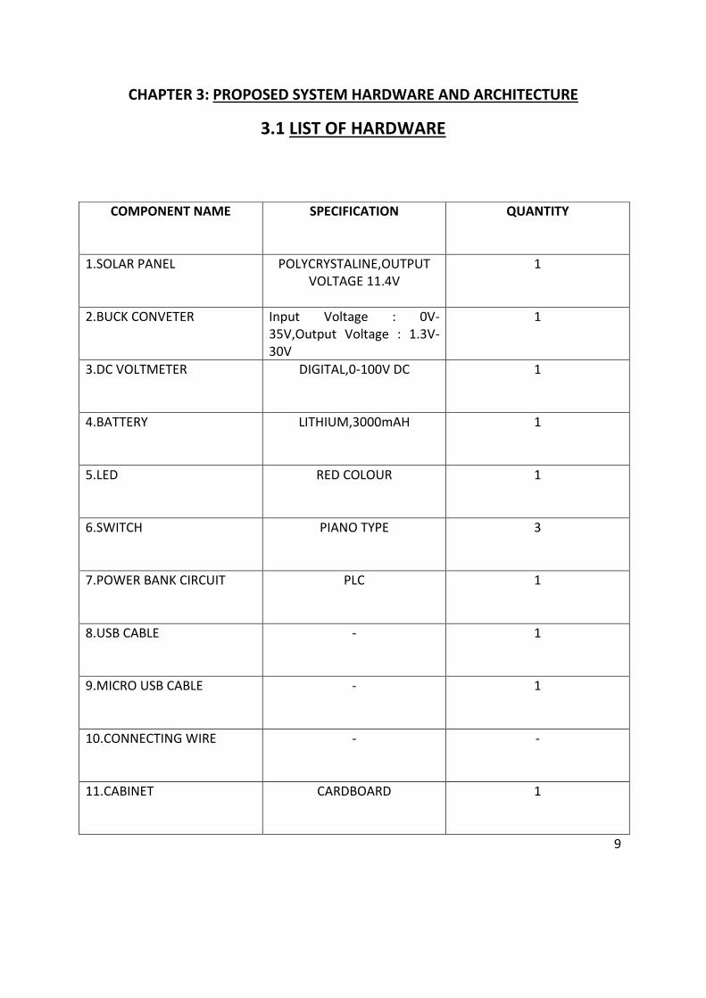
3.1 LIST OF HARDWARE
9
COMPONENT NAME SPECIFICATION QUANTITY
1.SOLAR PANEL POLYCRYSTALINE,OUTPUT VOLTAGE 11.4V
1
2.BUCK CONVETER Input Voltage : 0V-35V,Output Voltage : 1.3V-30V
1
3.DC VOLTMETER DIGITAL,0-100V DC 1
4.BATTERY LITHIUM,3000mAH 1
5.LED RED COLOUR 1
6.SWITCH PIANO TYPE 3
7.POWER BANK CIRCUIT PLC 1
8.USB CABLE - 1
9.MICRO USB CABLE - 1
10.CONNECTING WIRE - -
11.CABINET CARDBOARD 1
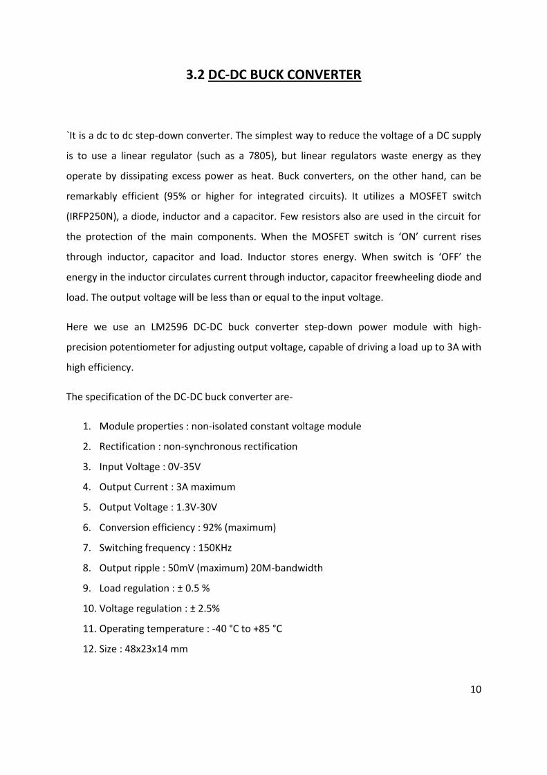
3.2 DC-DC BUCK CONVERTER
`It is a dc to dc step-down converter. The simplest way to reduce the voltage of a DC supply
is to use a linear regulator (such as a 7805), but linear regulators waste energy as they
operate by dissipating excess power as heat. Buck converters, on the other hand, can be
remarkably efficient (95% or higher for integrated circuits). It utilizes a MOSFET switch
(IRFP250N), a diode, inductor and a capacitor. Few resistors also are used in the circuit for
the protection of the main components. When the MOSFET switch is ‘ON’ current rises
through inductor, capacitor and load. Inductor stores energy. When switch is ‘OFF’ the
energy in the inductor circulates current through inductor, capacitor freewheeling diode and
load. The output voltage will be less than or equal to the input voltage.
Here we use an LM2596 DC-DC buck converter step-down power module with high-
precision potentiometer for adjusting output voltage, capable of driving a load up to 3A with
high efficiency.
The specification of the DC-DC buck converter are-
1. Module properties : non-isolated constant voltage module
2. Rectification : non-synchronous rectification
3. Input Voltage : 0V-35V
4. Output Current : 3A maximum
5. Output Voltage : 1.3V-30V
6. Conversion efficiency : 92% (maximum)
7. Switching frequency : 150KHz
8. Output ripple : 50mV (maximum) 20M-bandwidth
9. Load regulation : ± 0.5 %
10. Voltage regulation : ± 2.5%
11. Operating temperature : -40 °C to +85 °C
12. Size : 48x23x14 mm
10
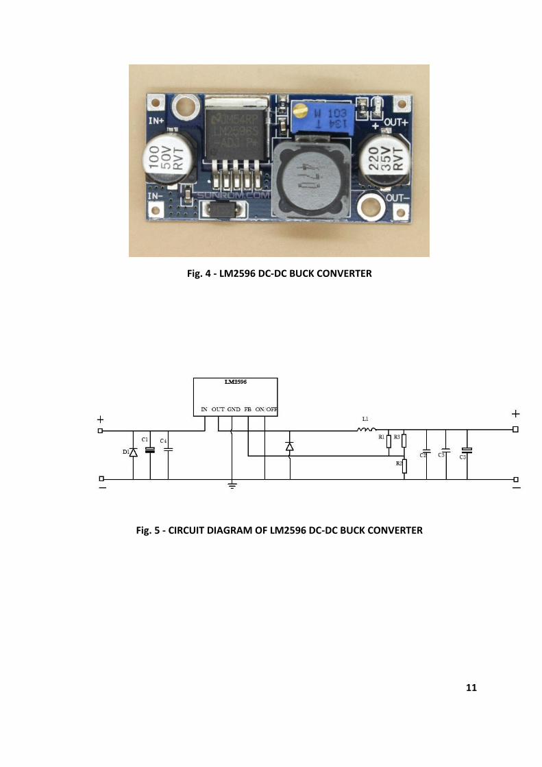
Fig. 4 - LM2596 DC-DC BUCK CONVERTER
Fig. 5 - CIRCUIT DIAGRAM OF LM2596 DC-DC BUCK CONVERTER
11
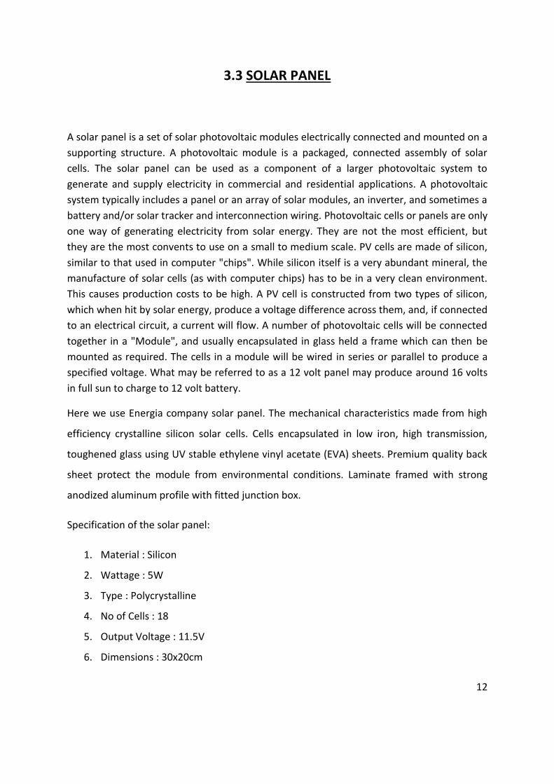
3.3 SOLAR PANEL
A solar panel is a set of solar photovoltaic modules electrically connected and mounted on a
supporting structure. A photovoltaic module is a packaged, connected assembly of solar
cells. The solar panel can be used as a component of a larger photovoltaic system to
generate and supply electricity in commercial and residential applications. A photovoltaic
system typically includes a panel or an array of solar modules, an inverter, and sometimes a
battery and/or solar tracker and interconnection wiring. Photovoltaic cells or panels are only
one way of generating electricity from solar energy. They are not the most efficient, but
they are the most convents to use on a small to medium scale. PV cells are made of silicon,
similar to that used in computer "chips". While silicon itself is a very abundant mineral, the
manufacture of solar cells (as with computer chips) has to be in a very clean environment.
This causes production costs to be high. A PV cell is constructed from two types of silicon,
which when hit by solar energy, produce a voltage difference across them, and, if connected
to an electrical circuit, a current will flow. A number of photovoltaic cells will be connected
together in a "Module", and usually encapsulated in glass held a frame which can then be
mounted as required. The cells in a module will be wired in series or parallel to produce a
specified voltage. What may be referred to as a 12 volt panel may produce around 16 volts
in full sun to charge to 12 volt battery.
Here we use Energia company solar panel. The mechanical characteristics made from high
efficiency crystalline silicon solar cells. Cells encapsulated in low iron, high transmission,
toughened glass using UV stable ethylene vinyl acetate (EVA) sheets. Premium quality back
sheet protect the module from environmental conditions. Laminate framed with strong
anodized aluminum profile with fitted junction box.
Specification of the solar panel:
1. Material : Silicon
2. Wattage : 5W
3. Type : Polycrystalline
4. No of Cells : 18
5. Output Voltage : 11.5V
6. Dimensions : 30x20cm
12
Fig. 6 – Solar Panel
13
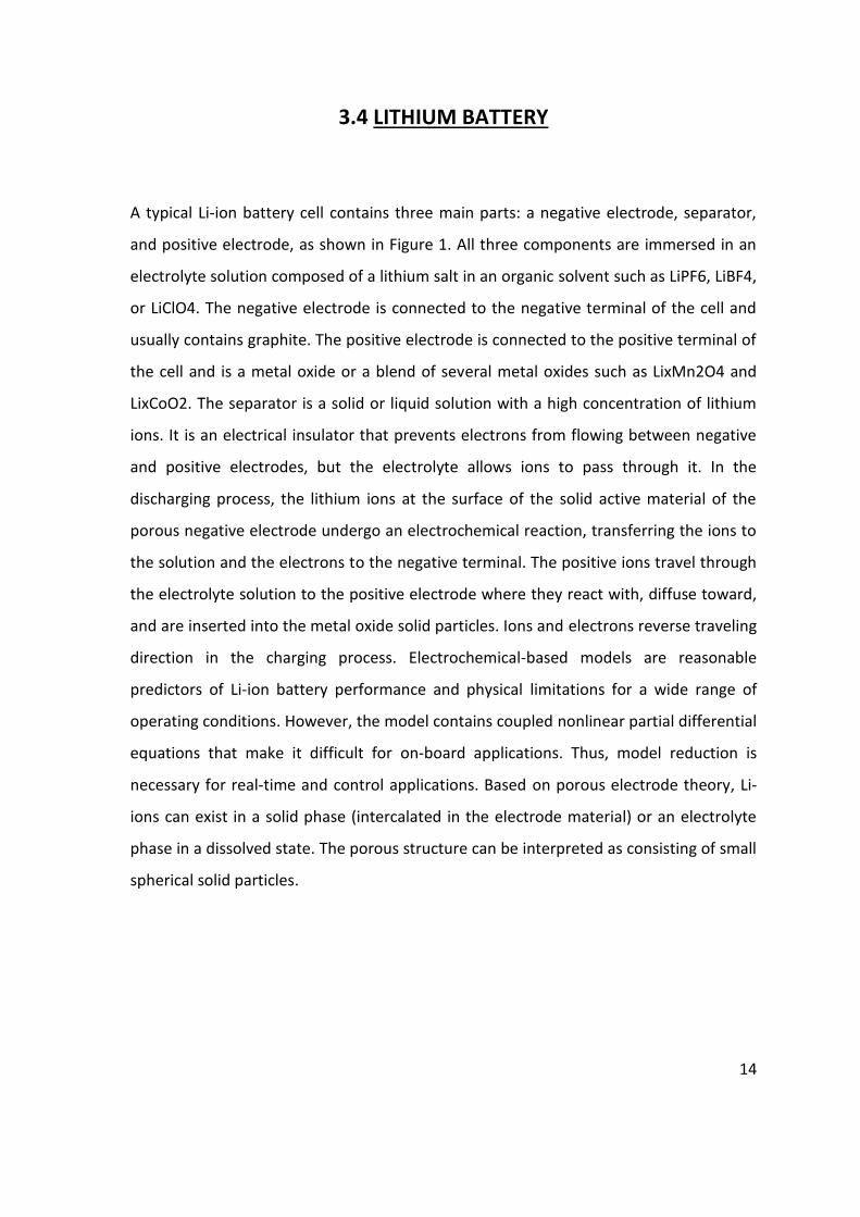
3.4 LITHIUM BATTERY
A typical Li-ion battery cell contains three main parts: a negative electrode, separator,
and positive electrode, as shown in Figure 1. All three components are immersed in an
electrolyte solution composed of a lithium salt in an organic solvent such as LiPF6, LiBF4,
or LiClO4. The negative electrode is connected to the negative terminal of the cell and
usually contains graphite. The positive electrode is connected to the positive terminal of
the cell and is a metal oxide or a blend of several metal oxides such as LixMn2O4 and
LixCoO2. The separator is a solid or liquid solution with a high concentration of lithium
ions. It is an electrical insulator that prevents electrons from flowing between negative
and positive electrodes, but the electrolyte allows ions to pass through it. In the
discharging process, the lithium ions at the surface of the solid active material of the
porous negative electrode undergo an electrochemical reaction, transferring the ions to
the solution and the electrons to the negative terminal. The positive ions travel through
the electrolyte solution to the positive electrode where they react with, diffuse toward,
and are inserted into the metal oxide solid particles. Ions and electrons reverse traveling
direction in the charging process. Electrochemical-based models are reasonable
predictors of Li-ion battery performance and physical limitations for a wide range of
operating conditions. However, the model contains coupled nonlinear partial differential
equations that make it difficult for on-board applications. Thus, model reduction is
necessary for real-time and control applications. Based on porous electrode theory, Li-
ions can exist in a solid phase (intercalated in the electrode material) or an electrolyte
phase in a dissolved state. The porous structure can be interpreted as consisting of small
spherical solid particles.
14
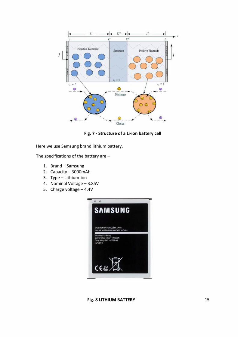
Fig. 7 - Structure of a Li-ion battery cell
Here we use Samsung brand lithium battery.
The specifications of the battery are –
1. Brand – Samsung 2. Capacity – 3000mAh 3. Type – Lithium-ion 4. Nominal Voltage – 3.85V 5. Charge voltage – 4.4V
Fig. 8 LITHIUM BATTERY 15
3.5 DC VOLTMETER
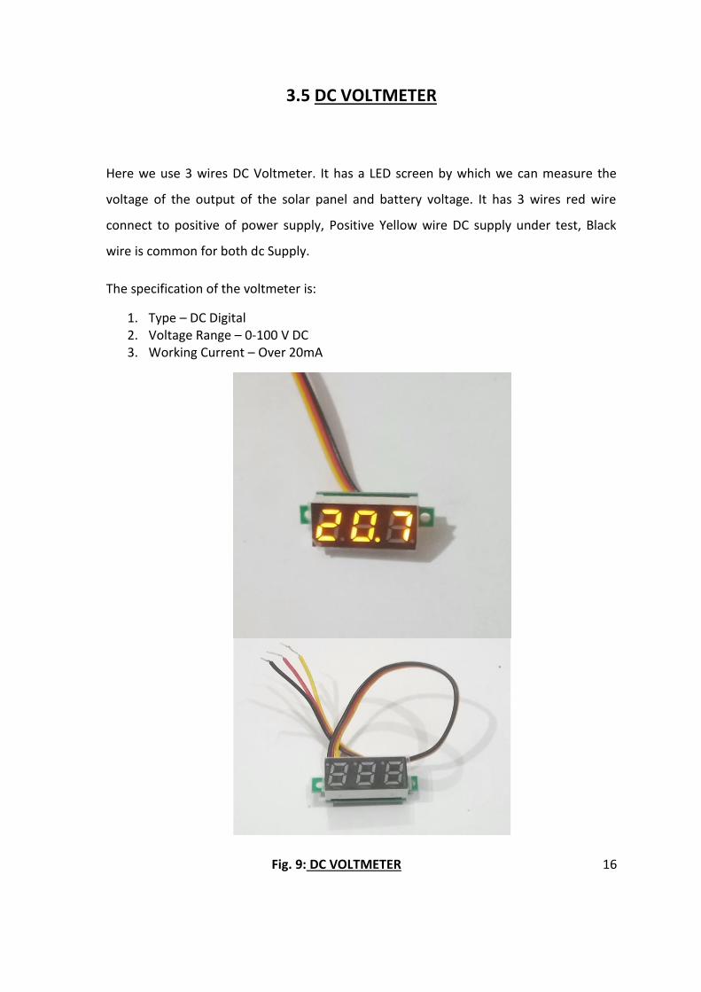
Here we use 3 wires DC Voltmeter. It has a LED screen by which we can measure the
voltage of the output of the solar panel and battery voltage. It has 3 wires red wire
connect to positive of power supply, Positive Yellow wire DC supply under test, Black
wire is common for both dc Supply.
The specification of the voltmeter is:
1. Type – DC Digital 2. Voltage Range – 0-100 V DC 3. Working Current – Over 20mA
Fig. 9: DC VOLTMETER 16

CHAPTER 4: MATHEMATICAL MODEL
4.1 MATHEMATICAL MODEL OF BUCK CONVERTER WORKIG
The output voltage of a buck converter is given by the equation (2.1)
Fig. 10 schematic of working of buck converter
17
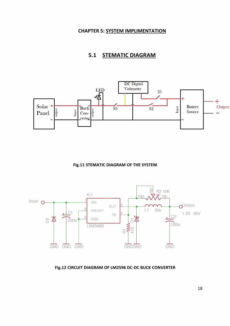
CHAPTER 5: SYSTEM IMPLIMENTATION
5.1 STEMATIC DIAGRAM
Fig.11 STEMATIC DIAGRAM OF THE SYSTEM
Fig.12 CIRCUIT DIAGRAM OF LM2596 DC-DC BUCK CONVERTER
18
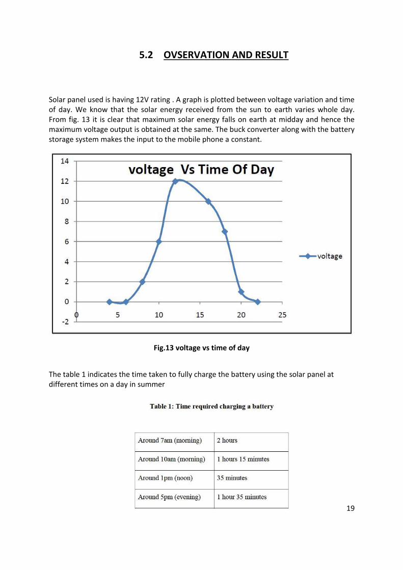
5.2 OVSERVATION AND RESULT
Solar panel used is having 12V rating . A graph is plotted between voltage variation and time of day. We know that the solar energy received from the sun to earth varies whole day. From fig. 13 it is clear that maximum solar energy falls on earth at midday and hence the maximum voltage output is obtained at the same. The buck converter along with the battery storage system makes the input to the mobile phone a constant.
Fig.13 voltage vs time of day
The table 1 indicates the time taken to fully charge the battery using the solar panel at different times on a day in summer
19
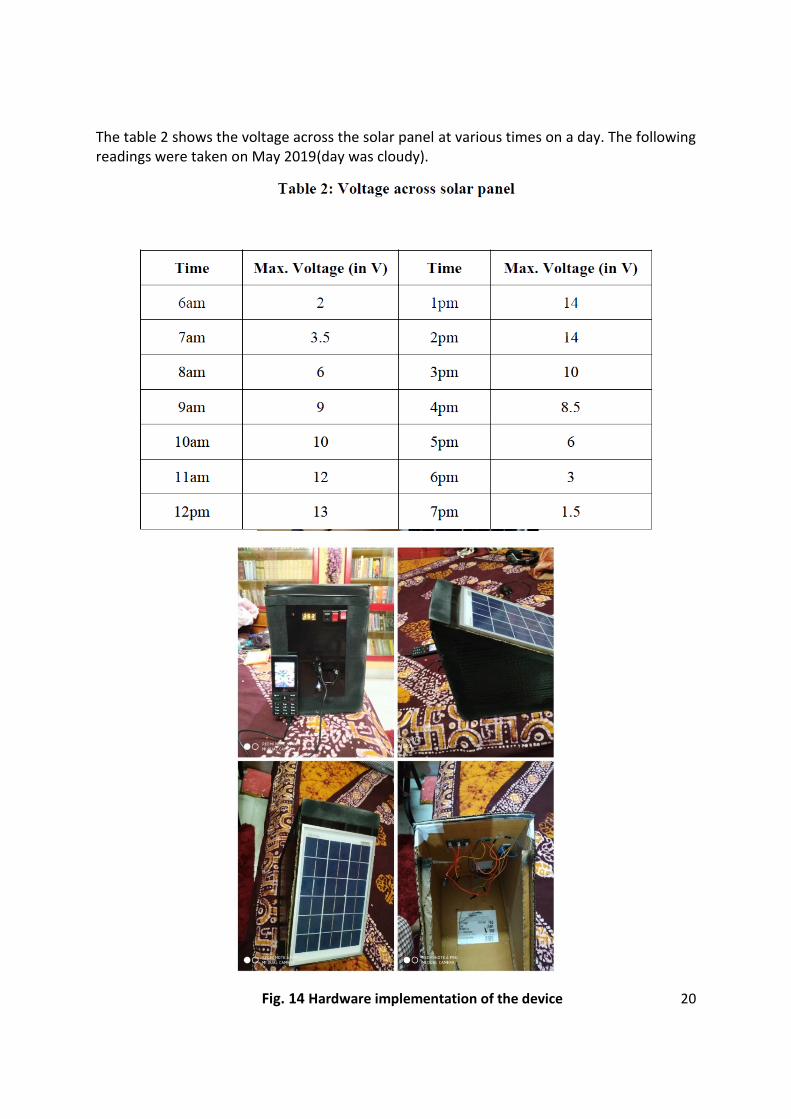
The table 2 shows the voltage across the solar panel at various times on a day. The following readings were taken on May 2019(day was cloudy).
Fig. 14 Hardware implementation of the device 20
CHAPTER 6: CONCLUSION AND FUTURE WORK
6.1 CONCLUSION
Solar act as good power supplies in bright sunlight. The only problem is the unregulated
voltage due to the variation in intensity of light. Voltage regulator is used to solve this
problem by regulating the output voltage. The charge so obtained is stored in the battery and
is given to the respective loads. The charge present in this battery is analysed and displayed
on an LCD. Solar powered cell phone chargers can be a better alternative to electrical cell
phone chargers. It will make the running cost of mobile phone reduced. For that purpose
designed an eco-friendly solar powered charger (SPC) for mobile charging which utilizes an
effective converter topology and microcontroller to ensure effective utilization of solar
energy. A SOLAR POWER MOBILE CHARGER can accommodate almost any model cell
phone. It can use the sun's energy to recharge a cell phone..
6.2 FUTURE SCOPE AND APPLICATION
Solar energy can only be harnessed when it is daytime and sunny. To overcome this, solar panels can be coupled with back-up battery which can store the excess power generated during the day and use it to provide energy to system in the absence of sunlight. The large
size of the solar panel makes the device bulky and non-portable. The solar panel should be
fabricated to cover the entire device, which can effectively reduce the size of the entire
device.
For low-power portable electronics, like calculators or small fans, a photovoltaic array may be a reasonable energy source rather than a battery. Solar chargers can charge lead acid or Ni-Cd battery bank up to 48 V and hundreds of ampere-hours (up to 400 Ah) capacity. Small portable models designed to charge a range of different mobile phones, cell phones, iPods or other portable audio equipment. Public solar chargers permanently installed in public places, such as parks, squares and streets, which passers-by can use for free.
21
REFERENCES
1. R. A. MASTROMAURO, M. LISERRE, AND A. DELL 'AQUILA, “CONTROL ISSUES IN
SINGLE-STAGE PHOTOVOLTAIC SYSTEMS: MPPT, CURRENT AND VOLTAGE
CONTROL,” IEEE TRANS. IND. INFORMAT., VOL. 8, NO. 2, PP. 241–254, MAY.
2012.
2. Z. Zhao, M. Xu,Q. Chen, J. S. Jason Lai, and Y. H. Cho, “Derivation, analysis, and
implementation of a boost–buck converter-based highefficiency pv inverter,”
IEEE Trans. Power Electron., vol. 27, no. 3, pp. 1304–1313, Mar. 2012.
3. M. Hanif, M. Basu, and K. Gaughan, “Understanding the operation of a Z-source
inverter for photovoltaic application with a design example, IET Power Electron.,
vol. 4, no. 3, pp. 278–287, 2011.
4. J.-M. Shen, H. L. Jou, and J. C. Wu, “Novel transformer-less grid connected power
converter with negative grounding for photovoltaic generation system,” IEEE
Trans. Power Electron., vol. 27, no. 4, pp. 1818– 1829, Apr. 2012.
5. Mohammed O Badawy, Ahmet S Yilmaz, Yilmaz Sozer, Iqbal Husain. Parallel
Power Processing Topology for Solar PV Applications. IEEE TRANSACTIONS ON
INDUSTRY APPLICATIONS, VOL. 50, NO. 2, MARCH/APRIL 2014
6. Solar Electricity Engineering of Photovoltaic System, by Lorezo E.
7. Power Electronics , by Bhimbra P.S.
8. An Energy-aware Survey on Mobile-phone Chargers, p. 8. Bonner, J. (2012),
Portable Solar Panel Charging Station, p.31.
9. Renewable Energy and Energy Efficiency Incentives: A summary of Federal
Programs, p.5. de Groot, H. (2008),
10. http://www.tpub.com/content/neets/14175/css/14175_130.htm
11. http://www.solar-facts.com/panels/
12. http://www.webbikeworld.com/r3/motorcycle-battery-charger/solar-
batterycharger/pulsetech-solar-battery-charger.htm
13. http://www.national.com/ds/LM/LM723.pdf
14. http://www.facstaff.bucknell.edu/mastascu/elessonshtml/LC/Capac1.htm
15. http://www.allaboutcircuits.com/vol_3/chpt_4/1.html
16. http://www.allaboutcircuits.com/vol_3/chpt_4/1.html#03071.png
17. http://science.howstuffworks.com/environmental/energy/solar-
cell.htm/battery.htm
18. http://en.wikipedia.org/wiki/Electrical_resistance_and_conductance
19. http://science.howstuffworks.com/environmental/energy/solar-cell1.htm
20. http://en.wikipedia.org/wiki/Electrical_element
21. http://en.wikipedia.org/wiki/Ohm
22
