solar hot water systems installation instructions 2 & 3 ... appropriate precautions to prevent...
TRANSCRIPT
SOLARcomfortSolar Hot Water
Systems2 & 3 Collector
Sets
Installation Instructions
LEAVE THESE INSTRUCTIONS WITH THEEND USER
Country of Destination GB/IE
1
TABLE OF CONTENTS
1. GENERAL INFORMATION ...............21.1 GUARANTEE .........................................21.2 SYSTEM CONTENTS ...............................21.3 SYSTEM INSTRUCTION BOOKS ..................21.4 SOLARCOMFORT .................................31.5 LIFESTYLE ............................................31.6 HOW THE SYSTEM WORKS......................3
2. SAFETY ............................................5
3. TECHNICAL DATA ............................63.1 TEMPERATURE/PRESSURE .......................63.2 COMPONENT LIST FOR 2 COLLECTOR SYSTEM
73.3 COMPONENT LIST FOR 3 COLLECTOR SYSTEM
83.4 COLLECTOR DIMENSIONS ........................93.5 FIXING STRAPS DIMENSIONS .................10
4. REGULATIONS & STANDARDS.....114.1 WATER REGULATIONS ..........................114.2 BUILDING REGULATIONS ........................114.3 GENERAL GUIDANCE ............................114.4 BRITISH & EUROPEAN STANDARDS .........124.5 UK REGULATIONS (WATER HEATING) .....124.6 UK REGULATIONS (CONSTRUCTION) .......124.7 EU DIRECTIVES ..................................134.8 OTHER PUBLICATIONS ..........................134.9 ELECTRICAL CONNECTION .....................134.10 THERMAL INSULATION ...........................13
5. INSTALLATION ...............................145.1 TOWN & COUNTRY PLANNING ...............145.2 HOUSE INSURANCE ..............................145.3 RISK ASSESSMENT ..............................145.4 ROOF CONDITION ................................145.5 POSITIONING COLLECTORS ....................145.6 CONSIDERATIONS FOR POSITIONING
COLLECTORS ......................................145.7 COLLECTOR INCLINATION .......................155.8 PIPEWORK & FITTINGS .........................155.9 INSULATION .........................................155.10 SIZING OF PIPES .................................155.11 PIPEWORK..........................................165.12 COLLECTOR COUPLINGS .......................165.13 COLLECTOR CONFIGURATIONS ...............175.14 TWO COLLECTOR SCHEMATIC ................18
5.15 THREE COLLECTOR SCHEMATIC .............195.16 FIXING STRAPS ...................................205.17 ROOF TYPES ......................................215.18 COLLECTOR FIXINGS ............................225.19 COLLECTOR FITTING PROCEDURE...........235.20 PLUMBING CONNECTIONS......................28
6. COMMISSIONING & SERVICING ..28
7. FLAT ROOF/GROUND MOUNTINGKIT ..................................................29
7.1 COMPONENT LIST ................................297.2 ANGLE OF INCLINATION .........................297.3 COLLECTOR ORIENTATION .....................307.4 DIMENSIONS .......................................307.5 FLAT ROOF CONDITION ........................307.6 GROUND PREPARATION.........................317.7 ASSEMBLY ..........................................31
2
1. GENERALINFORMATION
This manual is an integral and essential part of the product. It should bekept with the product.Please read carefully the instructions and notes about SOLARcomfortcontained in this manual as they provide important information regardingthe safe installation of the Solar Collectors.
IMPORTANTFailure to follow these instructions correctly may invalidate theguarantee.
IMPORTANTSolar domestic hot water heating systems must be installed tocomply with the current Building Regulations, British Standardsand any applicable local regulations.
The SOLARcomfort Collectors are guaranteed for 5 years againstmanufacturing defect - see terms and conditions of guarantee on backpage.
The complete SOLARcomfort solar water heating system is supplied inthe following consignments:-
1. 800201 Collector 1 per box
2. 3107024/5 Roof Fittings Kit 1 cardboard tube
3. 3820011/2 System Components 1 box
4. 3820001 Tyfocor antifreeze heat transfer fluid1 x 20l container
The following instruction booklets are supplied with a completeSOLARcomfort solar water heating system:-
1. SOLARcomfort Solar Hot Water Systems Collectors 2 & 3 CollectorSet.
Covers collector installation and plumbing connection.
Supplied in System Components box.
2. SOLARcomfort Solar Hot Water Systems Pump Group 40/60.
Covers installation, plumbing connection, system filling, flushing andcommissioning.
Supplied in System Components box.
3. Solar Controller AST 100
Covers installation, wiring connection and User Instructions.
Supplied in System Components box.
1.1 GUARANTEE
1.2 SYSTEM CONTENTS
1.3 SYSTEM INSTRUCTION BOOKS
3
SOLARcomfort systems are highly efficient and provide cost savings onthe energy used for heating hot water wherever they are used in the UK.However, the savings made will depend on local climate, installationcharacteristics and the household’s domestic hot water requirements.
It is important that the SOLARcomfort system is correctly sized for thelocal climate condition and the householders requirements.
After installation of the SOLARcomfort system, changes to thehouseholders use of hot water will be beneficial. Simple changes such asbathing in the evening instead of the morning and putting automatic washingmachines on when free hot water is available by solar energy.
In addition, the timing of the dwelling’s boiler controls must be modified toensure the ‘hot water ON’ time is set so that the water temperature in thecylinder is at a minimum by the start of the ‘solar day’.
The solar collectors are heated by the sun’s rays. The heat generated isstored in a hot water storage cylinder e.g. Ariston Primo twin coil stainlesssteel cylinder. The system controller continually compares the temperatureof the water within the cylinder with the temperature of the solar collectors.
Whenever the solar collectors are hotter than the water within the cylinder,the controller switches on the system’s circulating pump. The temperaturedifferential between the collectors and the cylinder is set via the AST 100Solar Controller. The heat transfer fluid within the solar system is thencirculated through the collectors and the cylinder’s heat exchanger, heatingthe cylinder in just the same way as a central heating boiler.
The cylinder typically has two coils (heat exchangers), the lower coil isheated by the solar system, therefore solar is the primary heat source.The upper cylinder is heated by an auxiliary heat source, typically a centralheating boiler, which is used to heat water when there is insufficient heatgenerated by the solar system. The Ariston Primo Twin cylinder also hastwo immersion heaters making it suitable for electric only heating systems.
The SOLARcomfort system is a forced circulation sealed system andtherefore requires an expansion vessel and a pressure relief valve (PRV),both supplied with SOLARcomfort.
The air separator with an integral manual air vent together with an automaticair vent positioned at the highest point on the system ensures that thesealed system remains free of air.
1.6 HOW THE SYSTEM WORKS
See fig. 1.6A
1.4 SOLARCOMFORT
1.5 LIFESTYLE

4
FIG. 1.6A SOLAR BASIC PRINCIPLES
Roof mounted collectors(two collector system shown)
Pump groupExpansion
vessel
Solar systemlow level fillpoint
Ariston ITSI 210/300twin coil cylinder
Upper coilheated by boileror other heatsource
Lower coil heated bysolar energy
AST 100Controller
Air vent
PR Valve
Solar systemdrain point
TemperatureSensor S1
TemperatureSensor S3
TemperatureSensor S2 PRV discharge
vessel
EnergyMonitoringSensor S4(option)

5
2. SAFETY WARNING - RISK TO LIFE
Correct procedures must be followed when lifting the collectors.
To satisfy Health and Safety requirements relating to the constructionindustry, the use of a crane or other lifting device may be required.
Take appropriate precautions to prevent accidents and falls whenworking on roofs.
Ensure correct personal protective clothing and safety equipmentare used when working on roofs.
Ensure that collectors lifted onto the roof or scaffold are alwayssecured to prevent them slipping and falling off the roof. Seriousinjury or death may result from collectors falling.
WARNING
The collectors must be correctly secured to the roof. The roof mustbe of adequate structure to support the collectors.
WARNING
During operation and commissioning the temperature of the heattransfer fluid within the system and collectors can reach temperatureshigh enough to present a risk of scalding. Never loosen fittings oropen vents when the system is hot.
WARNING
TYFOCOR LS Heat Transfer Fluid.
Although non-toxic it should not be swallowed.Refer to label on its container for storage and safety information.
A detailed technical specification is available from Ariston on request.
Caution
SOLARcomfort should be installed and commissioned by approvedcontractors. Failure to do so may invalidate the warranty.
Caution - Risk of damage to collectors
IMPORTANT! Always keep the glass side of the collectors fullycovered until the system is filled and ready for operation.
Always transport the collectors in an upright position. Never position thecollectors with the glass side facing down.
Leave collectors in their packaging until the time of installation. Do notallow the bottom side of the collectors to be damaged by sharp objects.
Never leave the collectors with the glass side down when they could beexposed to the weather, as rainwater could infiltrate the collector and causecondensation within the collector.
Note:Optional lifting handles are availablefrom Ariston (code 3107023).
6
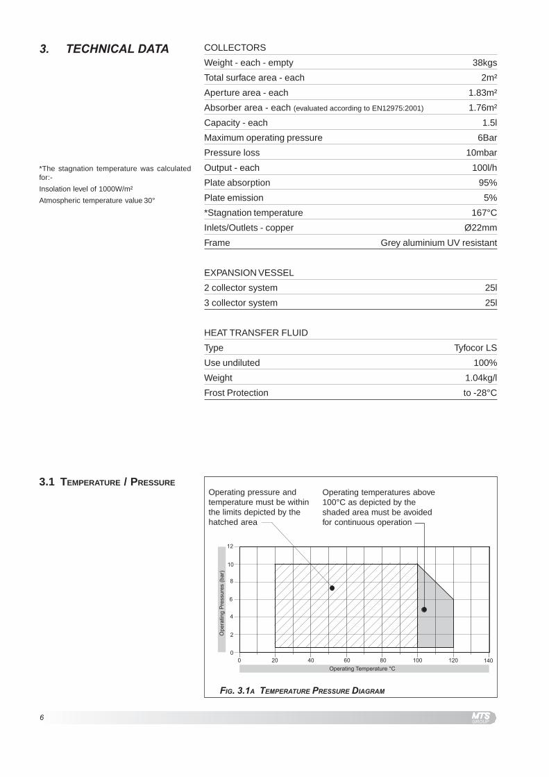
3. TECHNICAL DATA
Operating pressure andtemperature must be withinthe limits depicted by thehatched area
Operating temperatures above100°C as depicted by theshaded area must be avoidedfor continuous operation
FIG. 3.1A TEMPERATURE PRESSURE DIAGRAM
COLLECTORS
Weight - each - empty 38kgs
Total surface area - each 2m²
Aperture area - each 1.83m²
Absorber area - each (evaluated according to EN12975:2001) 1.76m²
Capacity - each 1.5l
Maximum operating pressure 6Bar
Pressure loss 10mbar
Output - each 100l/h
Plate absorption 95%
Plate emission 5%
*Stagnation temperature 167°C
Inlets/Outlets - copper Ø22mm
Frame Grey aluminium UV resistant
EXPANSION VESSEL
2 collector system 25l
3 collector system 25l
HEAT TRANSFER FLUID
Type Tyfocor LS
Use undiluted 100%
Weight 1.04kg/l
Frost Protection to -28°C
*The stagnation temperature was calculatedfor:-
Insolation level of 1000W/m²
Atmospheric temperature value 30°
3.1 TEMPERATURE / PRESSURE

7
FIG. 3.2A 2 COLLECTOR SYSTEM COMPONENT LIST
3.2 COMPONENT LIST FOR 2COLLECTOR SYSTEM
Listed below are all the components required to fit the collectors for theSOLARcomfort 2 collector system.
feR noitpircseD ytQ tnemngisnoC dekcaP
1 mm0002xmm0001srotcelloC 2 xobrep1 laudividnI2 mm0022htgnelsliaRtroppuS 2
tikgnixiffooR ebutdraobdraC1
3 spartsgnixiftrohS 44 spartsgnixifgnoL 45 )"2x21.oN(05x6ØswercsgnixifpartS 216 )trohs(spmalcretuO 47 )gnol(spmalcrennI 28 stekcarbmottobrotcelloC 49 stlobleetssselniatsxeh52x8M 2101 stunleetssselniatsxeh8M )eraps6cni( 8111 srehsawleetssselniats8M )swercsdoowrof21cni( 4221 mm22gnilpuocnoisserpmoC 3
ssarbrotcelloCtiksgnittif
metsySnidekcaPxobstnenopmoC
31 mm22dnepotsnoisserpmoC 241 mm22x"½xmm22TnoisserpmoC 251 hsubrecudeR"8/3ot"½ 161 m1xmm22epipelbixelfdetalusnI 2 noitcennocelbixelF
tikmetsySnidekcaPxobstnenopmoC71 mm22gnilpuocnoisserpmoC 2
81 tnevriacitamotuA 1metsySnidekcaPxobstnenopmoC
91 M"8/3xF"8/3evlavgnitalosI 1
02 snoitcurtsnIrotcelloC 1
12 tekcoptatsomrehT"½ 1 rellortnoC001TSAhtiwnidekcaP
Roof Fixing Kit (cardboard tube)
Collector brass fitting kitFlexible connecting kit
8
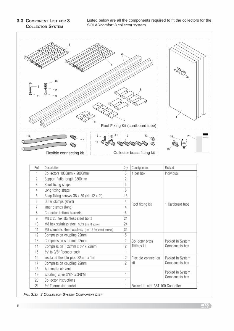
FIG. 3.3A 3 COLLECTOR SYSTEM COMPONENT LIST
3.3 COMPONENT LIST FOR 3COLLECTOR SYSTEM
Listed below are all the components required to fit the collectors for theSOLARcomfort 3 collector system.
Roof Fixing Kit (cardboard tube)
Collector brass fitting kitFlexible connecting kit
feR noitpircseD ytQ tnemngisnoC dekcaP
1 mm0002xmm0001srotcelloC 3 xobrep1 laudividnI2 mm0033htgnelsliaRtroppuS 2
tikgnixiffooR ebutdraobdraC1
3 spartsgnixiftrohS 64 spartsgnixifgnoL 65 )"2x21.oN(05x6ØswercsgnixifpartS 816 )trohs(spmalcretuO 47 )gnol(spmalcrennI 48 stekcarbmottobrotcelloC 69 stlobleetssselniatsxeh52x8M 4201 stunleetssselniatsxeh8M )eraps8cni( 4211 srehsawleetssselniats8M )swercsdoowrof81cni( 4321 mm22gnilpuocnoisserpmoC 5
ssarbrotcelloCtiksgnittif
metsySnidekcaPxobstnenopmoC
31 mm22dnepotsnoisserpmoC 241 mm22x"½xmm22TnoisserpmoC 251 hsubrecudeR"8/3ot"½ 161 m1xmm22epipelbixelfdetalusnI 2 noitcennocelbixelF
tikmetsySnidekcaPxobstnenopmoC71 mm22gnilpuocnoisserpmoC 2
81 tnevriacitamotuA 1metsySnidekcaPxobstnenopmoC
91 M"8/3xF"8/3evlavgnitalosI 102 snoitcurtsnIrotcelloC 112 tekcoptatsomrehT"½ 1 rellortnoC001TSAhtiwnidekcaP

9
3.4 COLLECTOR DIMENSIONS
FIG. 3.4A COLLECTOR DIMENSIONS

10
3.5 FIXING STRAPS DIMENSIONS
FIG. 3.5A FIXING STRAP DIMENSIONS
LONG
SHORT
11
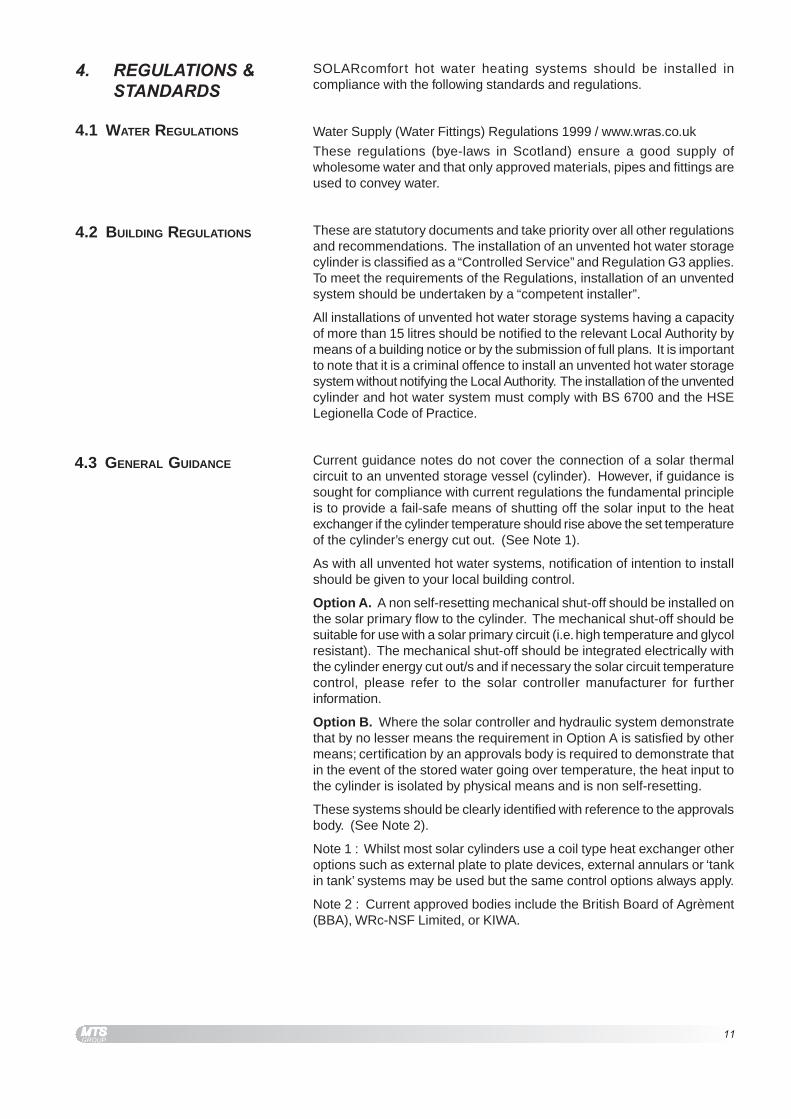
4. REGULATIONS &STANDARDS
SOLARcomfort hot water heating systems should be installed incompliance with the following standards and regulations.
Water Supply (Water Fittings) Regulations 1999 / www.wras.co.uk
These regulations (bye-laws in Scotland) ensure a good supply ofwholesome water and that only approved materials, pipes and fittings areused to convey water.
These are statutory documents and take priority over all other regulationsand recommendations. The installation of an unvented hot water storagecylinder is classified as a “Controlled Service” and Regulation G3 applies.To meet the requirements of the Regulations, installation of an unventedsystem should be undertaken by a “competent installer”.
All installations of unvented hot water storage systems having a capacityof more than 15 litres should be notified to the relevant Local Authority bymeans of a building notice or by the submission of full plans. It is importantto note that it is a criminal offence to install an unvented hot water storagesystem without notifying the Local Authority. The installation of the unventedcylinder and hot water system must comply with BS 6700 and the HSELegionella Code of Practice.
Current guidance notes do not cover the connection of a solar thermalcircuit to an unvented storage vessel (cylinder). However, if guidance issought for compliance with current regulations the fundamental principleis to provide a fail-safe means of shutting off the solar input to the heatexchanger if the cylinder temperature should rise above the set temperatureof the cylinder’s energy cut out. (See Note 1).
As with all unvented hot water systems, notification of intention to installshould be given to your local building control.
Option A. A non self-resetting mechanical shut-off should be installed onthe solar primary flow to the cylinder. The mechanical shut-off should besuitable for use with a solar primary circuit (i.e. high temperature and glycolresistant). The mechanical shut-off should be integrated electrically withthe cylinder energy cut out/s and if necessary the solar circuit temperaturecontrol, please refer to the solar controller manufacturer for furtherinformation.
Option B. Where the solar controller and hydraulic system demonstratethat by no lesser means the requirement in Option A is satisfied by othermeans; certification by an approvals body is required to demonstrate thatin the event of the stored water going over temperature, the heat input tothe cylinder is isolated by physical means and is non self-resetting.
These systems should be clearly identified with reference to the approvalsbody. (See Note 2).
Note 1 : Whilst most solar cylinders use a coil type heat exchanger otheroptions such as external plate to plate devices, external annulars or ‘tankin tank’ systems may be used but the same control options always apply.
Note 2 : Current approved bodies include the British Board of Agrèment(BBA), WRc-NSF Limited, or KIWA.
4.1 WATER REGULATIONS
4.2 BUILDING REGULATIONS
4.3 GENERAL GUIDANCE

12
4.4 BRITISH & EUROPEAN
STANDARDS
Connection of thermal solar heating systems
EN 12976: Thermal solar heating systems and their components(prefabricated systems).
ENV 12977: Thermal solar heating system and their components (bespokesystems).
BS5918: Latest version: Solar heating systems for domestic hot water.
Installation and equipment of DHW cylinders
BS5546: 2000 Specification for installation of hot water supplies for domesticpurposes, using gas-fired appliances of rated input not exceeding 70 kW.
BS6700: 1997 Specification for design, installation, testing andmaintenance, of servicing, supplying water for domestic use within buildingsand their curtilages.
The local water company by-laws.
Electrical connection
Current IEE wiring regulations.
Health and Safety document No 635 (Electricity at Work Regulations)
The Pressure Equipment Regulations (PED) 1999 - www.eurodyn.com
The Building Regulations (L1 A&B) 2006 and Domestic Heating ComplianceGuide - www.communities.gov.uk
The Building Regulations (P) 2005 - www.communities.gov.uk
Control of Substances Hazardous to Health Regulations (COSHH) 1994 -www.hse.gov.uk
Further details available from: www.hse.gov.uk
Health & Safety At Work Act (HSW) 1974
Work at Height Regulations 2005.
Reporting of Injuries, Diseases and Dangerous Occurrences Regulations(RIDDOR) 1995.
Management Health & Safety at Work Regulations (MHSWR) 1999.
Noise at Work Regulations 1989.
Construction (Health, Safety & Welfare) Regulations (CHSWA) 1996.
Electricity at Work Regulations 1989.
Construction Regulations (Head Protection) 1989.
Control of Substances Hazardous to Health Regulations (COSHH) 1994.
Construction (Design and Management) Regulations (CDM) 1994.
Personal Protective Equipment at Work Regulations 1992.
Lifting Operations and Lifting Equipment Regulations (LOLER) 1998.
Confined Spaces Regulations 1997.
Manual Handling Operations Regulations 1992.
The Workplace (Health, Safety and Welfare) Regulations 1992 (WHSWA).
Provision and Use of Work Equipment Regulations (PUWER) 1998.
Health and Safety (First Aid) Regulations 1981.
LZC - Low or zero carbon energy sources: strategic guide.
4.5 UK REGULATIONS
PARTICULARLY RELEVANT FOR
WATER HEATING EQUIPMENT
4.6 UK REGULATIONS
PARTICULARLY RELEVANT FOR
CONSTRUCTION

13
Further details available from: www.europa.eu.int
Construction Directive: 89/106/EEC
Electromagnetic: 89/336/EEC
Low voltage: 73/23/EEC
Machinery Directive: 98/37/EC
Preventing hot water scalding in bathrooms: using TMVs (IP 14/03).
DTI testing of solar systems (SP300275 1-3).
Review of issues related to active solar heating systems (SP300246).
Active solar performance and data review (SP300270).
Solar heating systems for hot water (BS 5918).
Hard water scale in hot water storage cylinders (IP13/93).
Heating systems in buildings – design for water-based heating systems(PrEN 12828).
Building log books (GPG 348).
Solar heating (CIBSE DBSP WGG).
Sun in Action II (ESTIF – Sun in Action II).
Minimising the risk of legionnaires’ disease (TM 13).
BRE Digest 489.
Energy Saving Trust - www.est.org.uk
CE131 Solar Water Heating Systems - Guidance for professionals,conventional indirect models.
BS7671 2001 Amended 2004
APD P:
P1 - Design, Installation, Inspection and Testing
P2 - Provision of information
Thermal Insulation Standard TIMSA (Thermal Insulation Manufacturersand Suppliers Association).
4.7 EU DIRECTIVES
4.8 OTHER PUBLICATIONS
4.9 ELECTRICAL CONNECTION
4.10 THERMAL INSULATION
14
5.1 TOWN & COUNTRY PLANNING
5. INSTALLATION The following topics should be considered prior to installing theSOLARcomfort system.
In general Solar Thermal Systems tend to be looked upon favourably byLocal Authority Planning Departments, although there are implications forlisted buildings and sensitive front elevations in some conservation areas.Some Local Authorities may consider solar panels as ‘PermittedDevelopment’ and therefore not requiring formal Planning Permission.
This may not be the case in all circumstances and contact with the localPlanning Authority is vital to determine the authority’s policy.
Permitted development rights do not necessarily apply in Areas ofOutstanding Natural Beauty, Conservation Areas, Sites of Special ScientificInterest and National Parks.
The householder should ensure that they are covered for the modifications.The Home Information Pack (HIP) may have specific requirementsregarding the installation of solar panels.
A risk assessment covering construction, water quality and bacterial risksmust be made before work starts. A site visit is required to assess therisks to workers, householders, members of the public and animals.
Prior to installation, the current condition of the roof must be assessed toensure that it is capable of withstanding the additional weight of the solarcollectors and roof mounting system. Where necessary, specialistpersonnel should be contacted to verify the suitability of the roof structure.
The solar collectors offer maximum energy performance when the glasssurface faces directly south. The angle of the dwelling in relation to thesun and site restrictions may lead to variations to this optimum southposition, a maximum recommended variation is 30° from due south.
A collector facing east side of south will give better performance in themorning than in the afternoon.
A collector facing west side of south will give better performance in theafternoon than in the morning.
Consideration should be given to the following when selecting a positionfor collectors.
1. The collectors must not be in the shade during daylight hours.The trimming or felling of trees may be advised.
2. In positions where exposure to high winds are likely, extra or alternativecollector mountings should be considered.
3. The collectors should be placed as close as possible to the storagecylinder to keep pipe runs to a minimum.
4. Collectors and the in loft pipework must be accessible for all necessarymaintenance work.
5. The possibility of bird or animal droppings fouling the surface of thecollectors e.g. overhead cables or branches.
5:2 HOUSE INSURANCE
5.3 RISK ASSESSMENT
5.5 POSITIONING COLLECTORS
5.6 CONSIDERATIONS FOR
POSITIONING COLLECTORS
5.4 ROOF CONDITION
15
5.9 INSULATION
5.10 SIZING OF PIPES
5.7 COLLECTOR INCLINATION
5.8 PIPEWORK AND FITTINGS
Collectors mounted on a pitched roof should always be parallel to the tilesi.e. at the same angle as the roof. There is no exception to this rule.
Collectors can be mounted on a flat roof or the ground, for such applicationsa special inclined angle fixing set is available - see section 7.
Taking into account that the heat transfer fluid within the system may reachhigh temperatures, the primary circuit should be copper, stainless steel(rigid and flexible) or carbon steel braided high temperature hose. Pipejoints and connections with other system components should also be ableto withstand the working temperatures and pressures. Thought should begiven to preventing corrosion due to dissimilar metals in contact.
All copper pipework must be Kite Marked BS EN1057 1996 Table X halfhard copper tube.
All fittings must be quality brass BS864-2 compression type.Brass olives are recommended as they produce a better seal.
Brazed or silver soldered joints are acceptable.
The use of joint compounds such as ‘Fernox White’ is recommended forcompression joints.
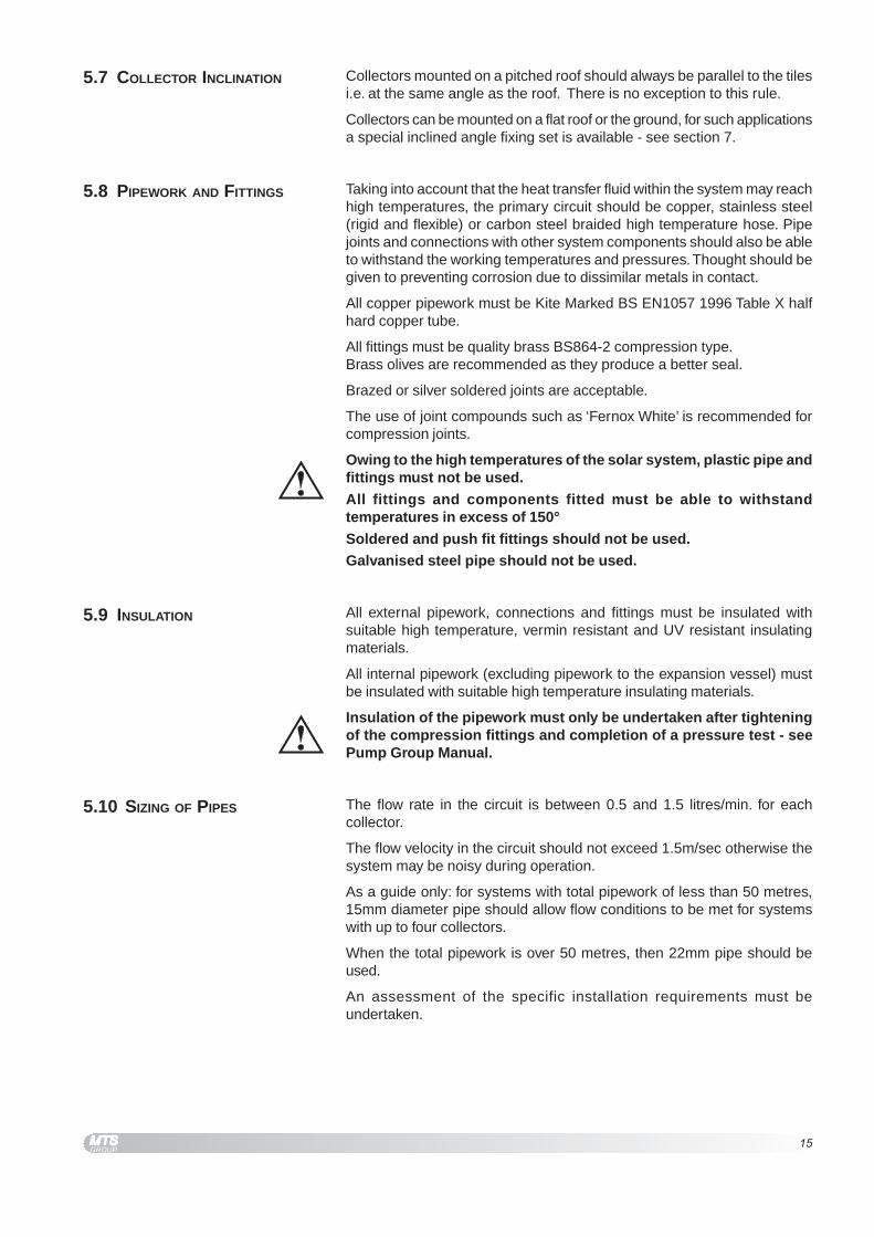
Owing to the high temperatures of the solar system, plastic pipe andfittings must not be used.
All fittings and components fitted must be able to withstandtemperatures in excess of 150°
Soldered and push fit fittings should not be used.Galvanised steel pipe should not be used.
All external pipework, connections and fittings must be insulated withsuitable high temperature, vermin resistant and UV resistant insulatingmaterials.
All internal pipework (excluding pipework to the expansion vessel) mustbe insulated with suitable high temperature insulating materials.
Insulation of the pipework must only be undertaken after tighteningof the compression fittings and completion of a pressure test - seePump Group Manual.
The flow rate in the circuit is between 0.5 and 1.5 litres/min. for eachcollector.
The flow velocity in the circuit should not exceed 1.5m/sec otherwise thesystem may be noisy during operation.
As a guide only: for systems with total pipework of less than 50 metres,15mm diameter pipe should allow flow conditions to be met for systemswith up to four collectors.
When the total pipework is over 50 metres, then 22mm pipe should beused.
An assessment of the specific installation requirements must beundertaken.
16
5.11 PIPEWORK The installation of pipework must be made in accordance with goodplumbing practice, the following points should be considered when installingpipework.
1. Pipe runs should be chosen to give the shortest most direct route tothe storage cylinder, with minimum bends. Tight bends should beavoided.
2. The falls of pipes should be arranged to allow the system to be drainedand vented.Low points, when unavoidable, should be fitted with a drain.High points, when unavoidable, should be fitted with a vent.
3. Where possible, all pipe runs should have a continuous slight inclineup to the highest point in the system to allow for natural venting of airfrom the system.
4. The automatic air vent supplied with the system should be fitted tothe highest point i.e. near the flow connection of the collectors.
5. Adequate support and fixing should be provided for all pipework toensure that inclines are maintained and sagging is prevented.
6. Owing to the high temperature differentials within the solar circuitconsideration should be given to the expansion of the pipework, expectup to 12mm on a 5 metre run. Pipes should be fitted with bracketsand devices that allow for expansion and contraction, rigid fixingsshould be avoided.
7. A drain point must be fitted at the lowest point of the solar circuit. Itmust be positioned at the down side of the non-return valve to ensurethe system can be fully drained.
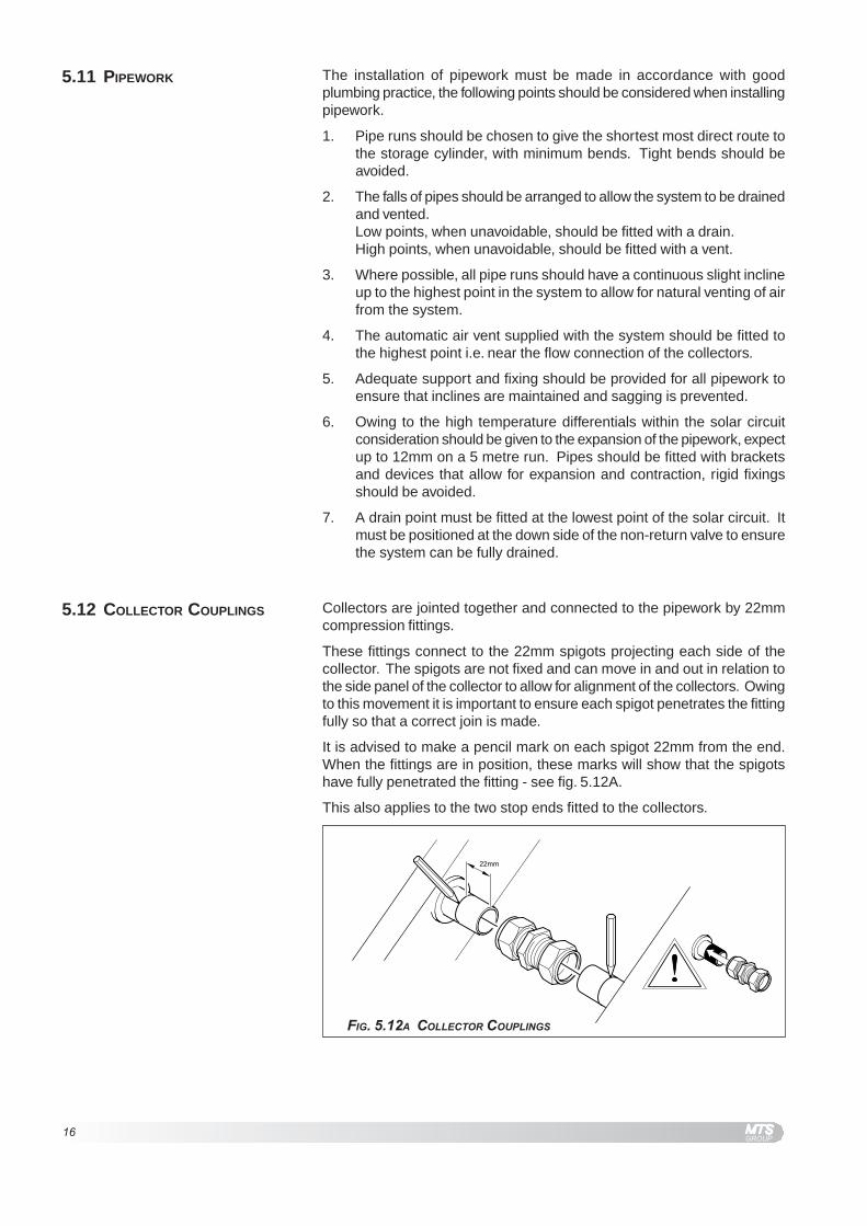
FIG. 5.12A COLLECTOR COUPLINGS
Collectors are jointed together and connected to the pipework by 22mmcompression fittings.
These fittings connect to the 22mm spigots projecting each side of thecollector. The spigots are not fixed and can move in and out in relation tothe side panel of the collector to allow for alignment of the collectors. Owingto this movement it is important to ensure each spigot penetrates the fittingfully so that a correct join is made.
It is advised to make a pencil mark on each spigot 22mm from the end.When the fittings are in position, these marks will show that the spigotshave fully penetrated the fitting - see fig. 5.12A.
This also applies to the two stop ends fitted to the collectors.
5.12 COLLECTOR COUPLINGS

17
5.13 COLLECTOR
CONFIGURATIONS
Two to seven collectors can be connected in series. When more thanseven are installed we recommend the panels are installed in a parallelconfiguration. Connection in series is recommended when a limited outputand high domestic hot water temperature is required.
FIG. 5.13A COLLECTOR SERIES CONFIGURATION
SERIES
ReturnFlow
Twin CoilIndirect Cylinder
Auxiliary heatsource
FIG. 5.13B COLLECTOR PARALLEL CONFIGURATION
PARALLEL
ReturnFlow
Twin CoilIndirect Cylinder
Auxiliary heatsource
18
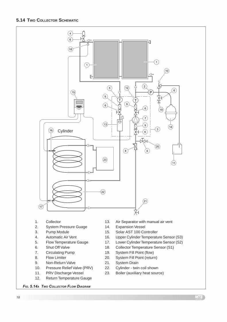
FIG. 5.14A TWO COLLECTOR FLOW DIAGRAM
Cylinder
5.14 TWO COLLECTOR SCHEMATIC
1. Collector2. System Pressure Guage3. Pump Module4. Automatic Air Vent5. Flow Temperature Gauge6. Shut Off Valve7. Circulating Pump8. Flow Limiter9. Non-Return Valve10. Pressure Relief Valve (PRV)11. PRV Discharge Vessel12. Return Temperature Gauge
13. Air Separator with manual air vent14. Expansion Vessel15. Solar AST 100 Controller16. Upper Cylinder Temperature Sensor (S3)17. Lower Cylinder Temperature Sensor (S2)18. Collector Temperature Sensor (S1)19. System Fill Point (flow)20. System Fill Point (return)21. System Drain22. Cylinder - twin coil shown23. Boiler (auxiliary heat source)

19
FIG. 5.15A THREE COLLECTOR FLOW DIAGRAM
Cylinder
5.15 THREE COLLECTOR SCHEMATIC
1. Collector2. System Pressure Guage3. Pump Module4. Automatic Air Vent5. Flow Temperature Gauge6. Shut Off Valve7. Circulating Pump8. Flow Limiter9. Non-Return Valve10. Pressure Relief Valve (PRV)11. PRV Discharge Vessel12. Return Temperature Gauge
13. Air Separator with manual air vent14. Expansion Vessel15. Solar AST 100 Controller16. Upper Cylinder Temperature Sensor (S3)17. Lower Cylinder Temperature Sensor (S2)18. Collector Temperature Sensor (S1)19. System Fill Point (flow)20. System Fill Point (return)21. System Drain22. Cylinder - twin coil shown23. Boiler (auxiliary heat source)
20
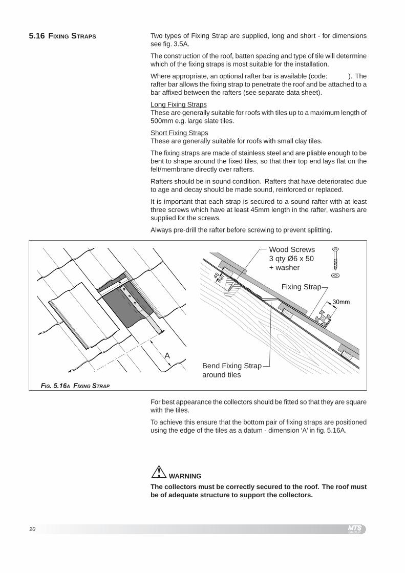
5.16 FIXING STRAPS Two types of Fixing Strap are supplied, long and short - for dimensionssee fig. 3.5A.
The construction of the roof, batten spacing and type of tile will determinewhich of the fixing straps is most suitable for the installation.
Where appropriate, an optional rafter bar is available (code: ). Therafter bar allows the fixing strap to penetrate the roof and be attached to abar affixed between the rafters (see separate data sheet).
Long Fixing StrapsThese are generally suitable for roofs with tiles up to a maximum length of500mm e.g. large slate tiles.
Short Fixing StrapsThese are generally suitable for roofs with small clay tiles.
The fixing straps are made of stainless steel and are pliable enough to bebent to shape around the fixed tiles, so that their top end lays flat on thefelt/membrane directly over rafters.
Rafters should be in sound condition. Rafters that have deteriorated dueto age and decay should be made sound, reinforced or replaced.
It is important that each strap is secured to a sound rafter with at leastthree screws which have at least 45mm length in the rafter, washers aresupplied for the screws.
Always pre-drill the rafter before screwing to prevent splitting.
Fixing Strap
Wood Screws3 qty Ø6 x 50+ washer
Bend Fixing Straparound tiles
FIG. 5.16A FIXING STRAP
For best appearance the collectors should be fitted so that they are squarewith the tiles.
To achieve this ensure that the bottom pair of fixing straps are positionedusing the edge of the tiles as a datum - dimension ‘A’ in fig. 5.16A.
WARNING
The collectors must be correctly secured to the roof. The roof mustbe of adequate structure to support the collectors.
A

21
5.17 ROOF TYPES
FIG. 5.17A ROOF TYPES FIXING
INTERLOCKING PROFILED TILES
For all profiled tiles, straps should befixed to align with the troughs in the tilesas opposed to the peaks, as shown.
FLAT TILE / SLATES
Bend the fixing strap to ensure a securefixing on the rafter. The exposed partof the strap must be beyond the edgeof the tile.
CLAY PLAIN TILED
For shorter tiles the tile battens can betoo close together and bending the roofbrackets to suit will be difficult.
Wood spacers can be fitted as shown.
Screws must be passed throughspacers and penetrate at least 45mminto the rafter.
An alternative method is to loosen thebattens and slide the fixing straps underthe battens. Care must be taken toensure the resulting roof structure issound.
22
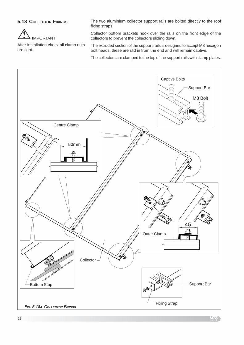
The two aluminium collector support rails are bolted directly to the rooffixing straps.
Collector bottom brackets hook over the rails on the front edge of thecollectors to prevent the collectors sliding down.
The extruded section of the support rails is designed to accept M8 hexagonbolt heads, these are slid in from the end and will remain captive.
The collectors are clamped to the top of the support rails with clamp plates.
5.18 COLLECTOR FIXINGS
M8 Bolt
Captive Bolts
Centre Clamp
Outer Clamp
Bottom Stop
Collector
Support Bar
Support Bar
FIG. 5.18A COLLECTOR FIXINGS
IMPORTANT
After installation check all clamp nutsare tight.
Fixing Strap

23
1. Fix lower fixing straps to rafters using the Ø6 x 50 screws provided,three screws minimum per strap. Rafters must be sound and screwsmust penetrate the rafters by at least 45mm.
Two straps for 2 Collectors, three straps 3 Collectors.
2. Slide bolts along one of the support rails to align with lower fixingstraps.
3. Locate bolts in the holes in the fixing straps, fit nuts with washers,align bar in required position and tighten nuts.
4. Measure for top rail.
5. Fit top fixing straps to rafter.
Two straps for 2 Collectors, three straps 3 Collectors.
6. Fit top support rail.
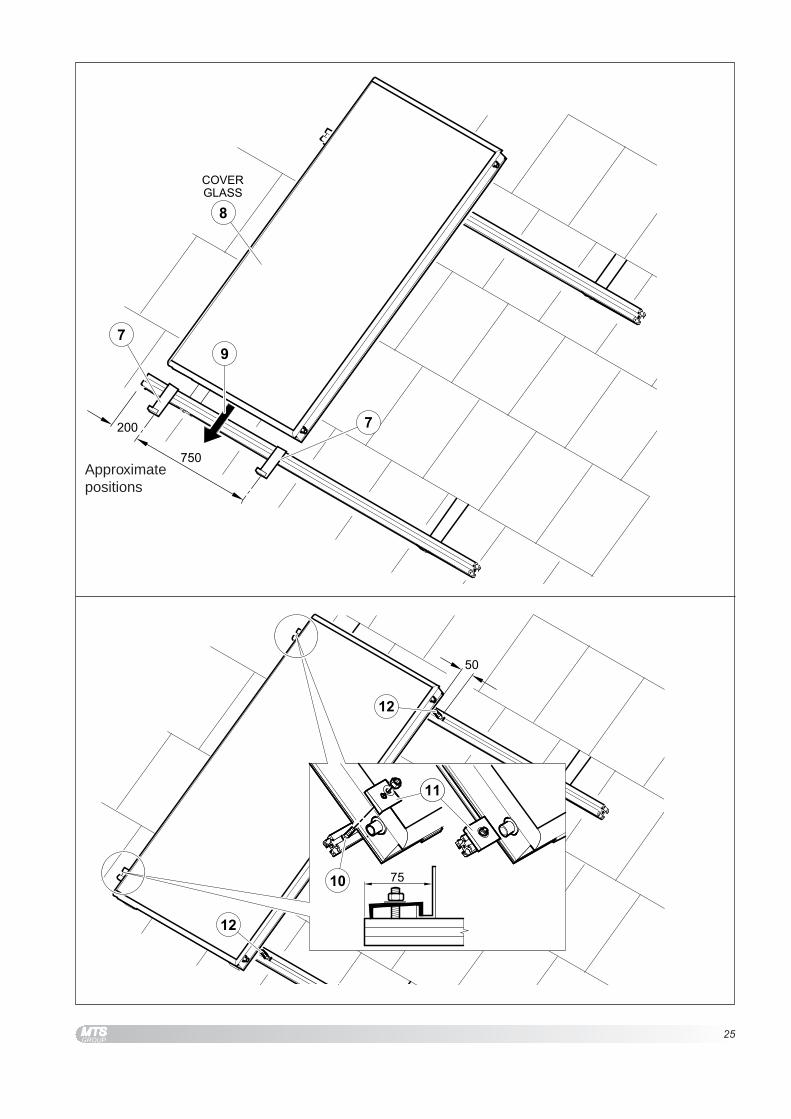
7. Slide on two bottom support brackets for first collector.
8. Unpack both collectors and cover glass side.
9. Lower first collector and locate the two bottom support brackets inthe bottom edge of the collector.
10. Slide in 1 bolt into outer end of each rail approx. 75mm.
11. Fix collector outer edge using one outer (short) clamp on each rail.
12. Slide 1 bolt from the other end of each rail to 50mm of the collector.
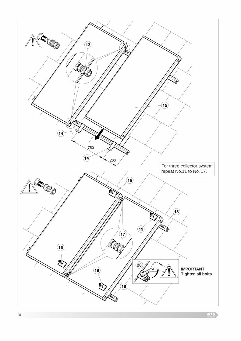
13. Attach 22mm compression coupling to both collector inner pipes.
Ensure that the pipes enter the couplings by 22mm - see 5.12.
14. Slide on two bottom support brackets for next collector.
15. Lower next collector on – take care not to damage under side ofcollector.Ensure that the pipes enter the couplings by 22mm - see 5.12.
16. Fit two inner (long) clamps between the collectors.
17. Fully tighten both centre pipe couplings.
For three collector system repeat No.11 to No. 17.
18. Slide 1 bolt from the end of each rail.
19. Fix second collector outer edge using one outer (short) clamp oneach rail.
20. Tighten all clamps.
21. Fit stop ends to the two connecting pipes not required.
22. Fit 22mm compression T to collector flow (top of collector). Fit collectorsensor S1 with ½” thermostat pocket, then fit flexible pipe to openend of T - also see fig. 5.20A.
23. Connect the remaining insulated flexible pipe to the return spigot using22mm compression coupling.
24. Make suitable weatherproof flashing where the pipes enter the roofspace.
5.19 COLLECTOR FITTING
PROCEDURE
CAUTION
EXTREME care must be taken NOTto puncture the under side of thecollectors.
IMPORTANT
After installation check all clamp nutsare tight.
Note:-Sensor S1 and ½” pocket are packedin with the AST 100 Controller.

24
25
Approximatepositions
26
IMPORTANTTighten all bolts
For three collector systemrepeat No.11 to No. 17.

27
Flow shown
28
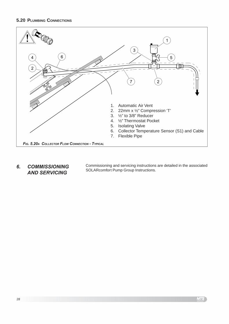
1. Automatic Air Vent2. 22mm x ½” Compression ‘T’3. ½” to 3/8” Reducer4. ½” Thermostat Pocket5. Isolating Valve6. Collector Temperature Sensor (S1) and Cable7. Flexible Pipe
FIG. 5.20A COLLECTOR FLOW CONNECTION - TYPICAL
5.20 PLUMBING CONNECTIONS
6. COMMISSIONINGAND SERVICING
Commissioning and servicing instructions are detailed in the associatedSOLARcomfort Pump Group Instructions.

29
7. FLAT ROOF/GROUNDMOUNTING KIT
Collectors can be mounted on a flat roof or on any prepared flat surfaceusing the Flat Roof/Ground mounting kit.
Product Code 3820011 - 2 Collector Kit
Product Code 3820012 - 3 Collector Kit
feR noitpircseDytQ
ROTCELLOC2TIK
ytQROTCELLOC3
TIK1 thgirpU 4 62 gnicarBssorC 4 63 tekcarBmottoBrotcelloC 4 64 pmalcmottoB 4 65 wercSburG52x8M 4 66 tuN8M 81 727 tloBnogaxeH52x8M 41 128 rehsaW8M 8 219 etalPgnitcennoC 2 4
7.1 COMPONENT LIST
FIG. 7.1A FLAT ROOF / GROUND MOUNTING KIT COMPONENT LIST
7.2 ANGLE OF INCLINATION The inclination of the collectors in relation to the horizontal surface willdepend on the season in which the collectors will be used, the type of useintended and the latitude of installation..
It is generally believed that to obtain optimum performance from solar panelsthe angle of inclination should be equal to the latitude of the location. Whenthis is so the solar panels will directly face the sun at noon on 21st Marchand 21st September.
This is correct for lower latitudes, however given that the UK has largevariations in radiation levels between summer and winter this is not strictlycorrect. In practice it has been found that optimum performance in SouthernEngland has been achieved by an angle of 35° to the horizontal.
Note:-Section 7.2 only applies to flat roofand level ground applications, forpitched roofs the collectors arealways at the same angle as the roofpitch.
30
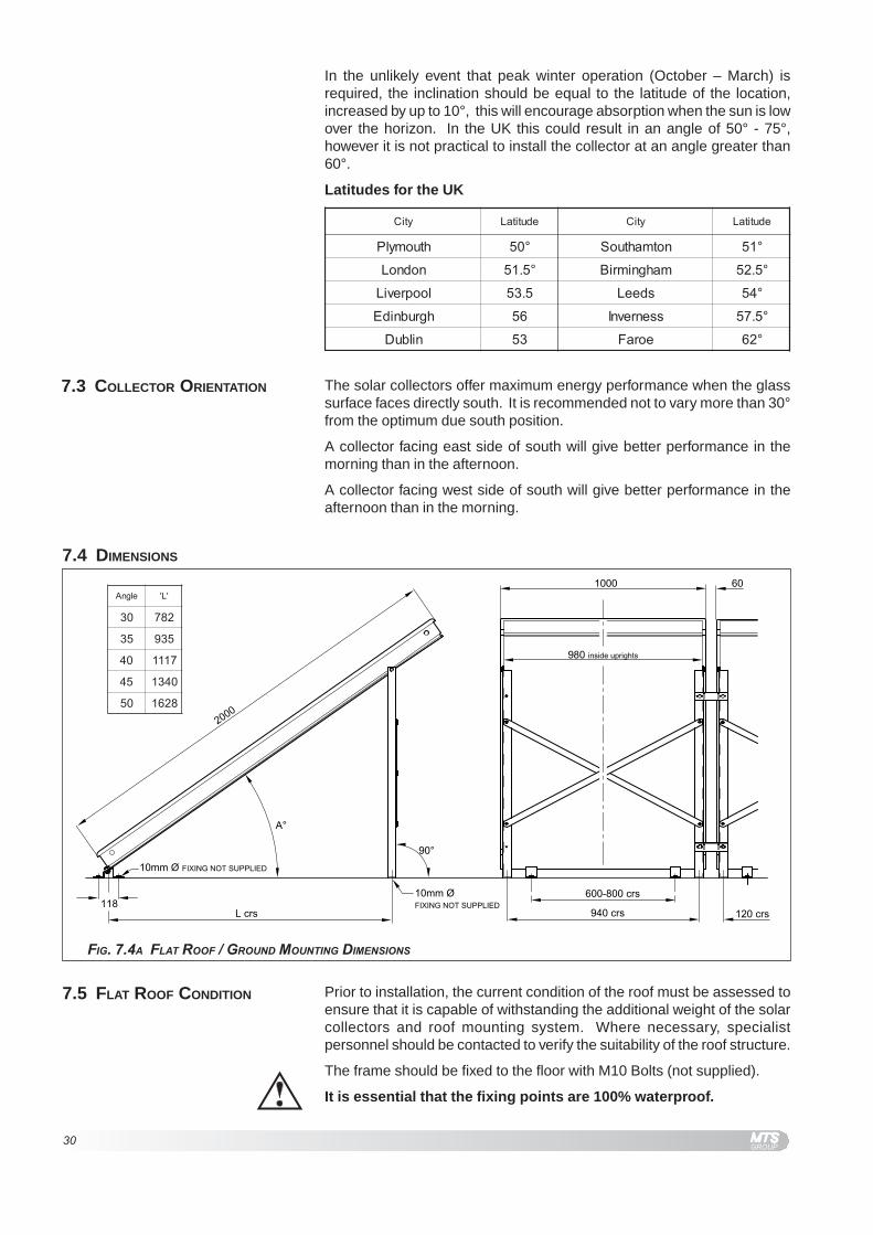
7.5 FLAT ROOF CONDITION Prior to installation, the current condition of the roof must be assessed toensure that it is capable of withstanding the additional weight of the solarcollectors and roof mounting system. Where necessary, specialistpersonnel should be contacted to verify the suitability of the roof structure.
The frame should be fixed to the floor with M10 Bolts (not supplied).
It is essential that the fixing points are 100% waterproof.
FIG. 7.4A FLAT ROOF / GROUND MOUNTING DIMENSIONS
7.4 DIMENSIONS
elgnA 'L'
03 287
53 539
04 7111
54 0431
05 8261
ytiC edutitaL ytiC edutitaL
htuomylP °05 notmahtuoS °15
nodnoL °5.15 mahgnimriB °5.25
loopreviL 5.35 sdeeL °45
hgrubnidE 65 ssenrevnI °5.75
nilbuD 35 eoraF °26
In the unlikely event that peak winter operation (October – March) isrequired, the inclination should be equal to the latitude of the location,increased by up to 10°, this will encourage absorption when the sun is lowover the horizon. In the UK this could result in an angle of 50° - 75°,however it is not practical to install the collector at an angle greater than60°.
Latitudes for the UK
The solar collectors offer maximum energy performance when the glasssurface faces directly south. It is recommended not to vary more than 30°from the optimum due south position.
A collector facing east side of south will give better performance in themorning than in the afternoon.
A collector facing west side of south will give better performance in theafternoon than in the morning.
7.3 COLLECTOR ORIENTATION
31
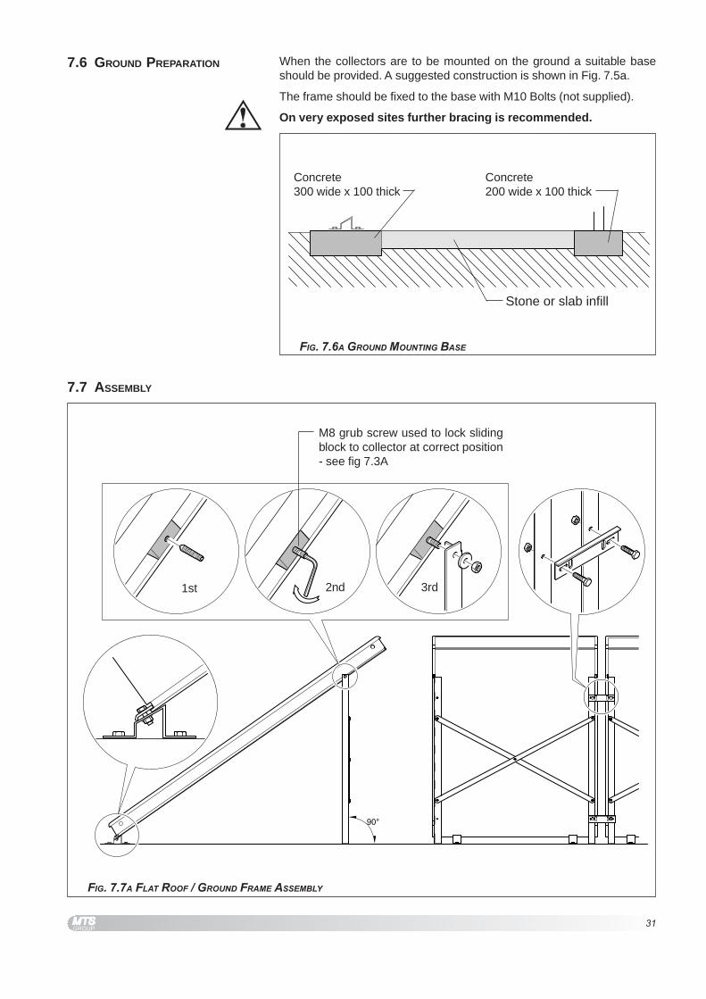
1st 2nd 3rd
M8 grub screw used to lock slidingblock to collector at correct position- see fig 7.3A
7.7 ASSEMBLY
FIG. 7.7A FLAT ROOF / GROUND FRAME ASSEMBLY
When the collectors are to be mounted on the ground a suitable baseshould be provided. A suggested construction is shown in Fig. 7.5a.
The frame should be fixed to the base with M10 Bolts (not supplied).
On very exposed sites further bracing is recommended.
7.6 GROUND PREPARATION
FIG. 7.6A GROUND MOUNTING BASE
Stone or slab infill
Concrete300 wide x 100 thick
Concrete200 wide x 100 thick

32
NOTES
MTS (GB) Limited
MTS Building
Hughenden Avenue
High Wycombe
Bucks HP13 5FT
Tel.:- 01494 755600
Fax:- 01494 759775
www.mtsgroup.com/uk
email: [email protected]
Technical Service Hot Line 0870 241 8180
Customer Service Help Desk 0870 600 9888
TERMS AND CONDITIONS OF GUARANTEE
The SOLARcomfort Collectors are guaranteed for 5 years againstmanufacturing defect.
Please read these terms and conditions which are in addition to any terms andconditions detailed in this book or any registration card supplied with yourappliance.
SOLARcomfort solar thermal systems must only be installed andcommissioned by Ariston trained and approved installers. Failure to complywith this requirement will invalidate the warranty.
A charge will be made to the owner of the appliance if:-
1. The reason for any service visit is as a direct result of a failure to install theappliance in accordance with the manufacturer’s instructions.
2. Your installer does not complete the necessary commissioning processand procedure as detailed in the Installation and Operating Instruction manuals.
3. Your appliance is not serviced on or before the 12 month anniversary ofinstallation.
4. Our service engineer calls as requested and the failure is a non-manufacturing defect.
Failure to pay an invoice for any such occurrence will be assumed by MTS thatyou accept that your appliance has not been installed correctly and understandthat any manufacturer’s guarantee has been withdrawn.
On the 12 month anniversary of the appliance installation, you must have it servicedto continue any guarantee offered into the following year. Failure to do so willinvalidate your guarantee and should an MTS engineer be required to attend andno proof of service documentation is made available, then MTS will charge.
If you have a problem with commissioning on installation, please contact ourTechnical Department on 0870 241 8180.
Sol
ar H
ot W
ater
Sys
tem
s2
and
3 C
olle
ctor
Set
s M
anua
l 06/
02/2
007