solar-field sp300 (lingua inglese)
DESCRIPTION
Technical manual for photovoltaic free-fields with single pile foundationsTRANSCRIPT

Solar-field SP300Technical manual for photovoltaic free-fields with single pile foundations
1. Single pile support systems for free-fields
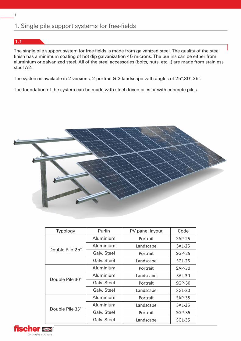
The single pile support system for free-fields is made from galvanized steel. The quality of the steel finish has a minimum coating of hot dip galvanization 45 microns. The purlins can be either from aluminium or galvanized steel. All of the steel accessories (bolts, nuts, etc...) are made from stainless steel A2.
The system is available in 2 versions, 2 portrait & 3 landscape with angles of 25°,30°,35°.
The foundation of the system can be made with steel driven piles or with concrete piles.
1
1.1
Typology Purlin PV panel layout Code
Double Pile 25°
Aluminium Portrait SAP-25
Aluminium Landscape SAL-25
Galv. Steel Portrait SGP-25
Galv. Steel Landscape SGL-25
Double Pile 30°
Aluminium Portrait SAP-30
Aluminium Landscape SAL-30
Galv. Steel Portrait SGP-30
Galv. Steel Landscape SGL-30
Double Pile 35°
Aluminium Portrait SAP-35
Aluminium Landscape SAL-35
Galv. Steel Portrait SGP-35
Galv. Steel Landscape SGL-35
2. Assembly of support system
S
2
2.1 PILE FOUNDATION
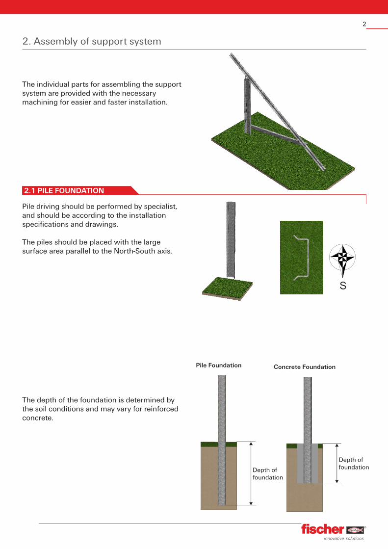
The individual parts for assembling the support system are provided with the necessary machining for easier and faster installation.
Pile driving should be performed by specialist, and should be according to the installation specifications and drawings.
The piles should be placed with the large surface area parallel to the North-South axis.
The depth of the foundation is determined by the soil conditions and may vary for reinforced concrete.
Depth of foundation
Depth of foundation
Pile Foundation Concrete Foundation
3
2.2 INSTALLING THE GIRDER CONNECTOR
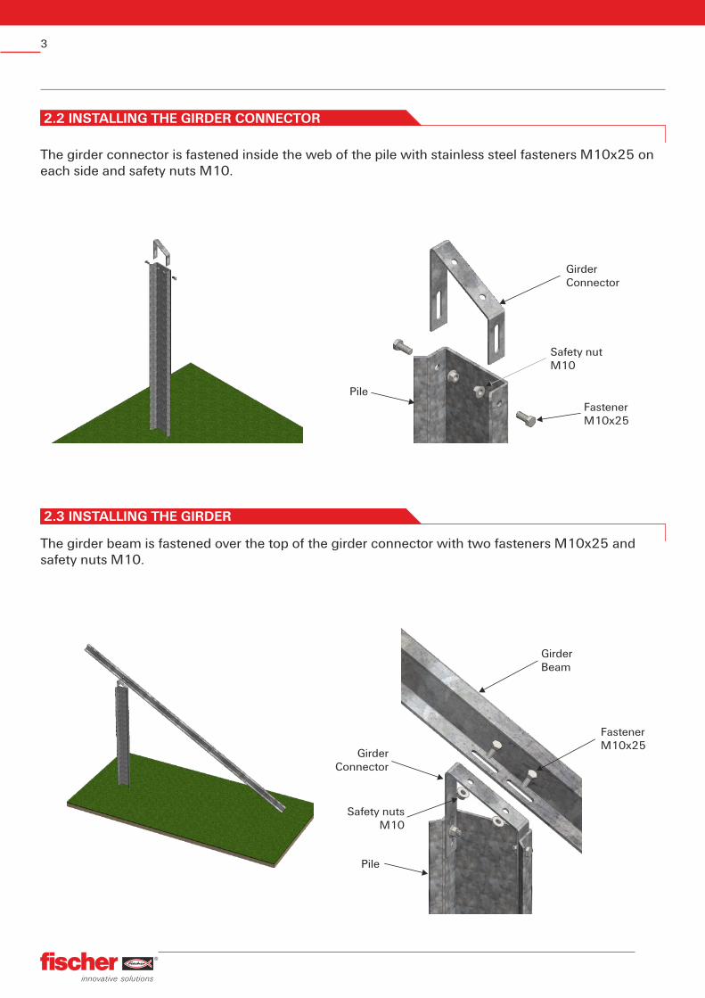
The girder connector is fastened inside the web of the pile with stainless steel fasteners M10x25 on each side and safety nuts M10.
Girder Connector
Safety nutM10
FastenerΜ 10x25
Pile
The girder beam is fastened over the top of the girder connector with two fasteners M10x25 and safety nuts M10.
2.3 INSTALLING THE GIRDER
GirderConnector
Safety nutsM10
FastenerΜ 10x25
GirderBeam
Pile
4
2.4 INSTALLING DIAGONAL BRACING
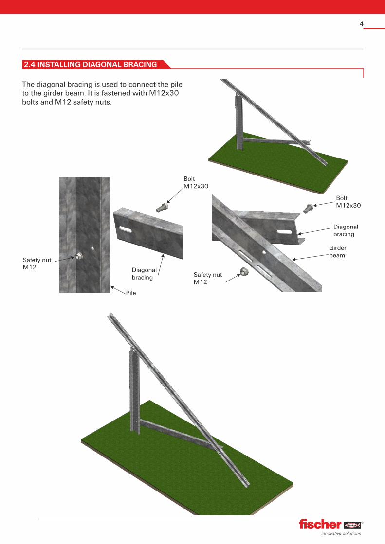
The diagonal bracing is used to connect the pile to the girder beam. It is fastened with M12x30 bolts and M12 safety nuts.
BoltΜ 12x30
Diagonalbracing
Diagonalbracing
Girderbeam
Safety nut Μ 12
Safety nut Μ 12
BoltΜ 12x30
Pile
5
3,0m
3,0m
3,0m
Drawing Description
Fastener Μ 12x30
Fastener Μ 10x25
56 Nm
56 Nm
Torque
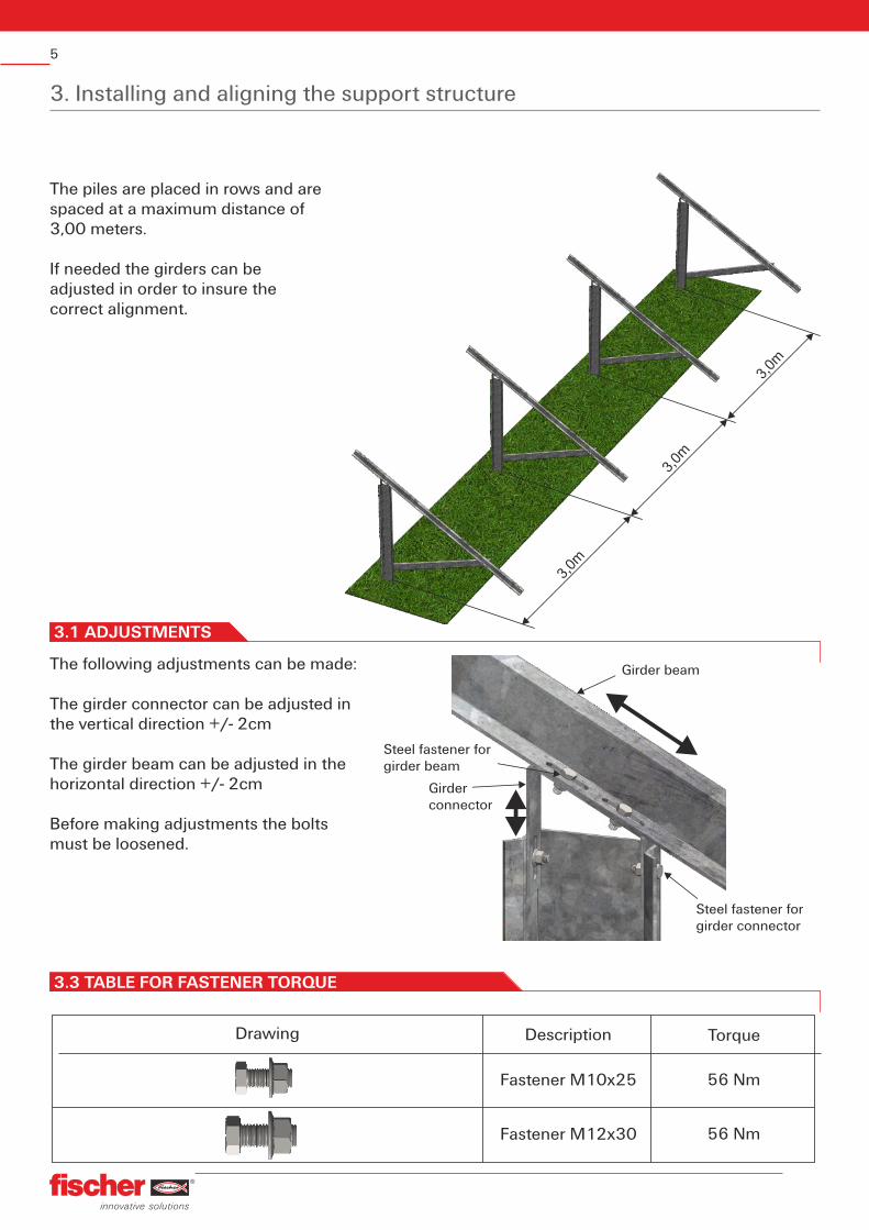
3. Installing and aligning the support structure
The piles are placed in rows and are spaced at a maximum distance of 3,00 meters.
If needed the girders can be adjusted in order to insure the correct alignment.
3.1 ADJUSTMENTS
The following adjustments can be made:
The girder connector can be adjusted in the vertical direction +/- 2cm
The girder beam can be adjusted in the horizontal direction +/- 2cm
Before making adjustments the bolts must be loosened.
Girder connector
Steel fastener for girder beam
Girder beam
Steel fastener for girder connector
3.3 TABLE FOR FASTENER TORQUE
6
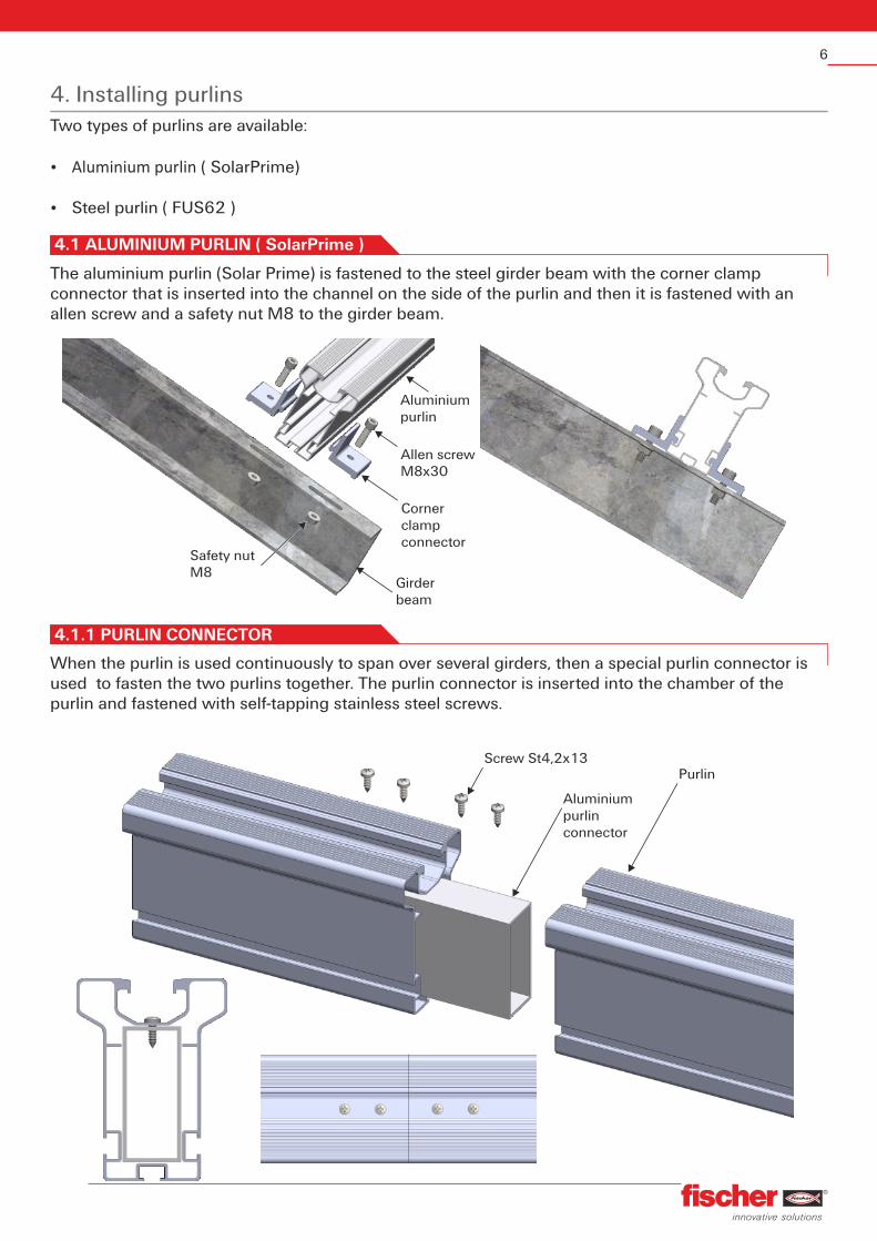
4. Installing purlinsTwo types of purlins are available:
Ÿ Aluminium purlin ( SolarPrime)
Ÿ Steel purlin ( FUS62 )
The aluminium purlin (Solar Prime) is fastened to the steel girder beam with the corner clamp connector that is inserted into the channel on the side of the purlin and then it is fastened with an allen screw and a safety nut M8 to the girder beam.
4.1 ALUMINIUM PURLIN ( SolarPrime )
Girder beam
Safety nutM8
Corner clampconnector
Allen screw M8x30
Aluminiumpurlin
When the purlin is used continuously to span over several girders, then a special purlin connector is used to fasten the two purlins together. The purlin connector is inserted into the chamber of the purlin and fastened with self-tapping stainless steel screws.
Aluminium purlin connector
PurlinScrew St4,2x13
4.1.1 PURLIN CONNECTOR
7
For connecting the steel purlin (FUS62) to the girder beam, use an allen screw M12x30 and M12 washer with safety nut M12.
4.2 STEEL PURLIN ( FUS62 )
Allen screw M12x30
Girderbeam
Safety nutM12
Steelpurlin
When the purlin is used continuously to span over several girders, then a special purlin connector is used to fasten the two purlins together. The purlin connector is fastened to the under side of the purlin with four allen screws M12x30 and washers M12. Safety nuts are not required as the connector has been threaded to directly receive the M12 bolts.
4.2.1 PURLIN CONNECTOR
Allen screw M12x30
Steelpurlin
Steel purlinconnector
Washer M12
Washer M12
8
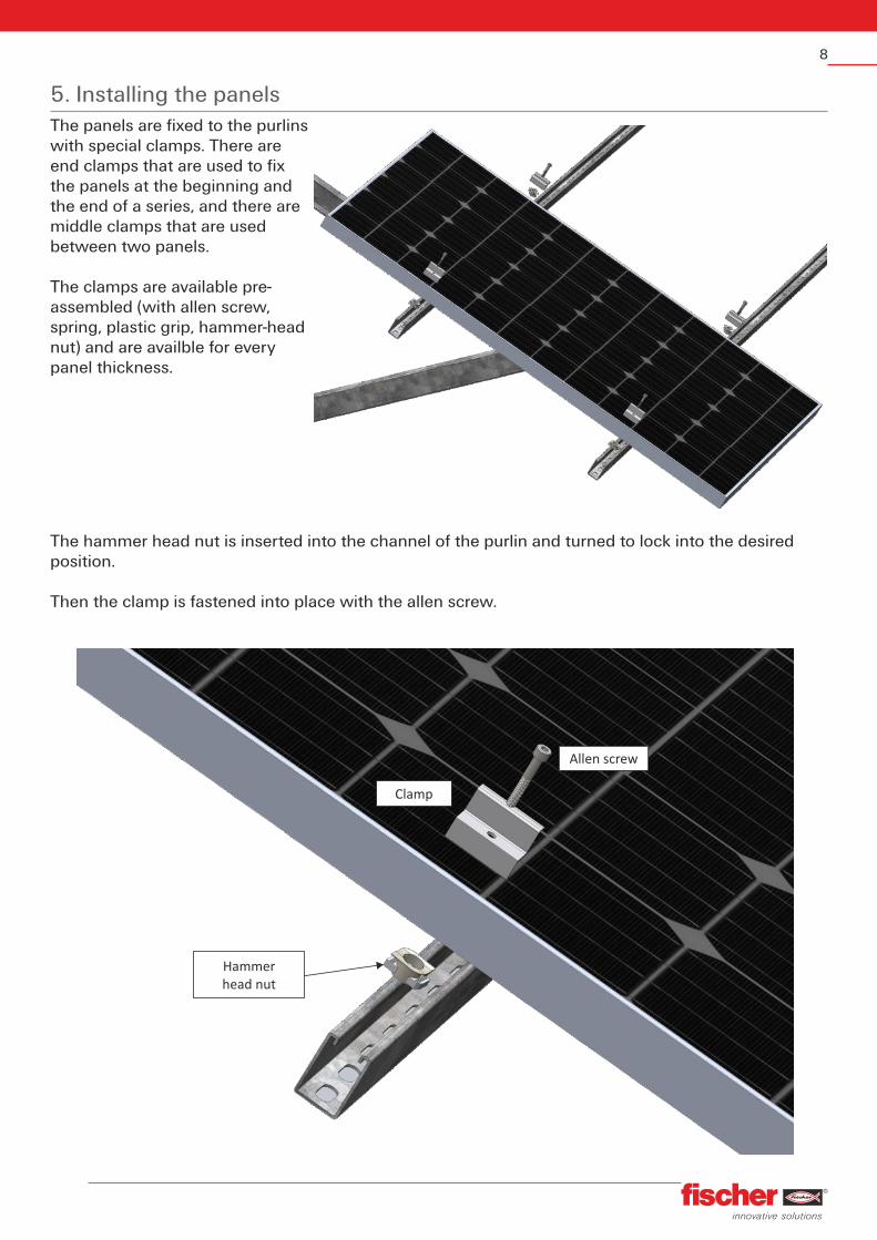
5. Installing the panelsThe panels are fixed to the purlins with special clamps. There are end clamps that are used to fix the panels at the beginning and the end of a series, and there are middle clamps that are used between two panels.
The clamps are available pre-assembled (with allen screw, spring, plastic grip, hammer-head nut) and are availble for every panel thickness.
The hammer head nut is inserted into the channel of the purlin and turned to lock into the desired position.
Then the clamp is fastened into place with the allen screw.
Hammer head nut
Clamp
Allen screw
9
F
L
L/2
1- point load
FF
L
L/3 L/3
2- point load
q
L
2 supports - Uniformly load
qL qL
L L
3 supports - Uniformly load
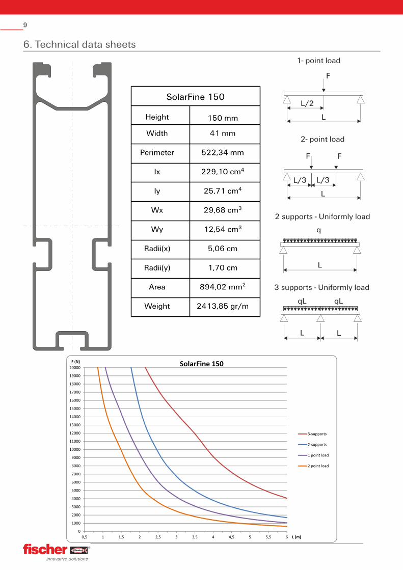
SolarFine 150
Height 150 mm
Width 41 mm
Perimeter 522,34 mm
Ix 4229,10 cm
Iy 425,71 cm
Wx 329,68 cm
Wy 312,54 cm
Radii(x) 5,06 cm
Radii(y) 1,70 cm
Area 2894,02 mm
Weight 2413,85 gr/m
6. Technical data sheets
0
1000
2000
3000
4000
5000
6000
7000
8000
9000
10000
11000
12000
13000
14000
15000
16000
17000
18000
19000
20000
0,5 1 1,5 2 2,5 3 3,5 4 4,5 5 5,5 6
F (N)
L (m)
SolarFine 150
3-supports
2-supports
1 point load
2 point load
10
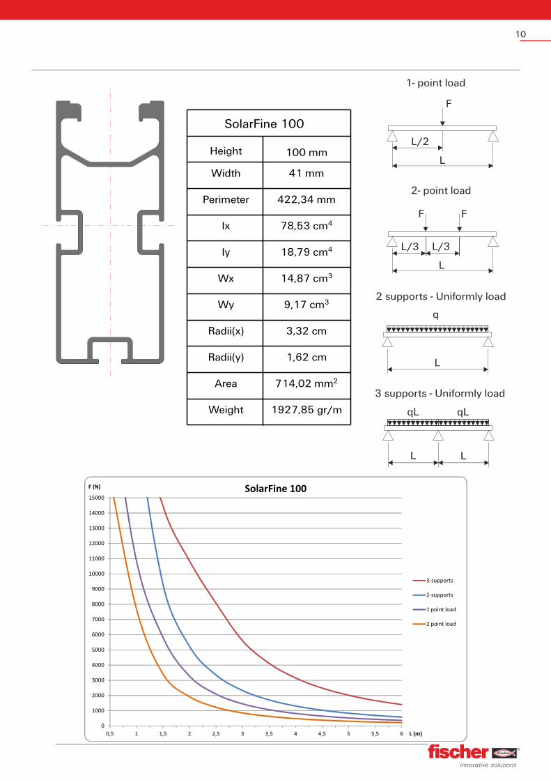
SolarFine 100
Height 100 mm
Width 41 mm
Perimeter 422,34 mm
Ix 478,53 cm
Iy 418,79 cm
Wx 314,87 cm
Wy 39,17 cm
Radii(x) 3,32 cm
Radii(y) 1,62 cm
Area 2714,02 mm
Weight 1927,85 gr/m
0
1000
2000
3000
4000
5000
6000
7000
8000
9000
10000
11000
12000
13000
14000
15000
0,5 1 1,5 2 2,5 3 3,5 4 4,5 5 5,5 6
F (N)
L (m)
SolarFine 100
3-supports
2-supports
1 point load
2 point load
F
L
L/2
1- point load
FF
L
L/3 L/3
2- point load
q
L
2 supports - Uniformly load
qL qL
L L
3 supports - Uniformly load
11
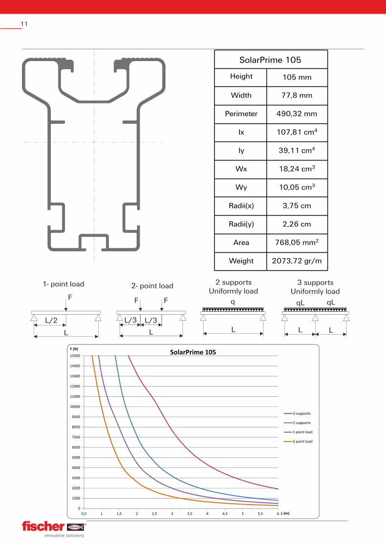
SolarPrime 105
Height 105 mm
Width 77,8 mm
Perimeter 490,32 mm
Ix 4107,81 cm
Iy 439,11 cm
Wx 318,24 cm
Wy 310,05 cm
Radii(x) 3,75 cm
Radii(y) 2,26 cm
Area 2768,05 mm
Weight 2073,72 gr/m
0
1000
2000
3000
4000
5000
6000
7000
8000
9000
10000
11000
12000
13000
14000
15000
0,5 1 1,5 2 2,5 3 3,5 4 4,5 5 5,5 6
F (N)
L (m)
SolarPrime 105
3-supports
2-supports
1 point load
2 point load
F
L
L/2
1- point load
FF
L
L/3 L/3
2- point load
q
L
2 supportsUniformly load
qL qL
L L
3 supportsUniformly load
12
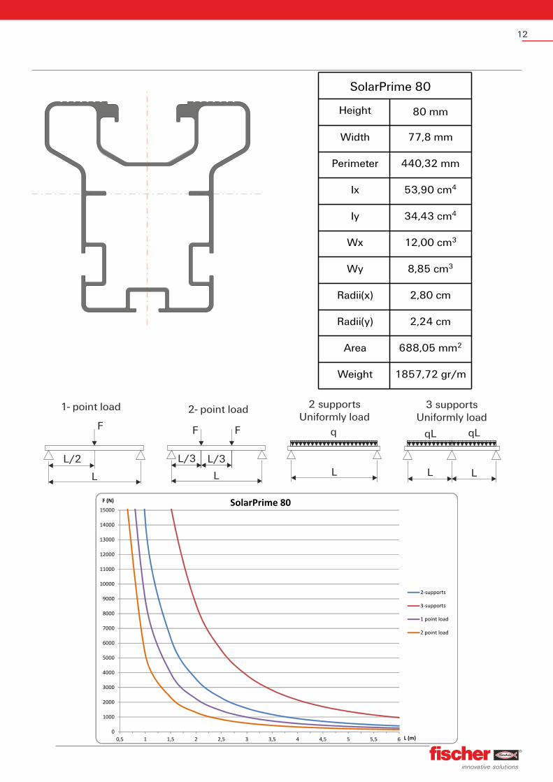
SolarPrime 80
Height 80 mm
Width 77,8 mm
Perimeter 440,32 mm
Ix 453,90 cm
Iy 434,43 cm
Wx 312,00 cm
Wy 38,85 cm
Radii(x) 2,80 cm
Radii(y) 2,24 cm
Area 2688,05 mm
Weight 1857,72 gr/m
0
1000
2000
3000
4000
5000
6000
7000
8000
9000
10000
11000
12000
13000
14000
15000
0,5 1 1,5 2 2,5 3 3,5 4 4,5 5 5,5 6
F (N)
L (m)
SolarPrime 80
2-supports
3-supports
1 point load
2 point load
F
L
L/2
1- point load
FF
L
L/3 L/3
2- point load
q
L
2 supportsUniformly load
qL qL
L L
3 supportsUniformly load

13
FUS 62
Height 62 mm
Width 41 mm
Perimeter 365,19 mm
Ix 417,70 cm
Iy 412,90 cm
Wx 35,62 cm
Wy 36,29 cm
Area 2405 mm
Weight 3270 gr/m
0
500
1000
1500
2000
2500
3000
3500
4000
4500
5000
5500
6000
6500
7000
7500
8000
8500
9000
9500
10000
0,5 1 1,5 2 2,5 3 3,5 4 4,5 5 5,5 6
F (N)
L (m)
FUS 62
3-supports
2-supports
1 point load
2 point load
F
L
L/2
1- point load
FF
L
L/3 L/3
2- point load
q
L
2 supports - Uniformly load
qL qL
L L
3 supports - Uniformly load
14
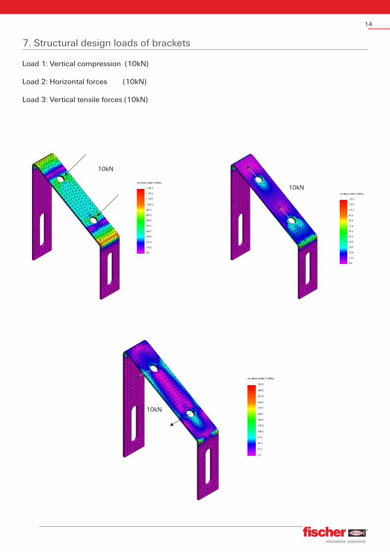
7. Structural design loads of brackets
Load 1: Vertical compression (10kN)
Load 2: Horizontal forces (10kN)
Load 3: Vertical tensile forces (10kN)
10kN
10kN
10kN

1958, the beginning.2012, world-wide.
Founded in 1958, the fischer brand is synonymous for safe, innovative and sophisticated technical solutions which set new standards in fixing engineering. The products and applications are unique fixing systems that are invented and produced by fischer. That is the reason that there exist unlimited solutions and a large range of applications, and today is recognised as the leader in the market of fixing systems.
ChemicalFixing Systems
Drill Bits& Accessories
MetalFixing Systems
MEPFixing Systems
Exterior InsulationFixing Systems
Fasteners Chemical Building products
NylonFixing Systems
Gypsum BoardFixing Systems
PhotovoltaicFixing Systems
fischer Hellas Emporiki EPE
www.fischer.gr
G. Papandreou 125, Metamorphosi 144 52, AthensTel.: +30 210 28 38 167, Fax: +30 210 28 38 [email protected]
The contents of this manual are subject to change without prior notice. Fischer Hellas Em
poriki EPE is not responsible for typographical errors. PLS012 05/2012