soiled tray conveyor systems - caddy corp · soiled tray conveyor cm cf-10 series intertek series...
TRANSCRIPT

CADDY CORPORATIONAir SystemsFood Service Equipment
Soiled TrayConveyorSystems
PROJECT:
ITEM NO:
LOCATION:
page 1 of 3
All specifications subject to change without notice
SOILED TRAY CONVEYOR
CF-10 SERIES
CM
Intertek
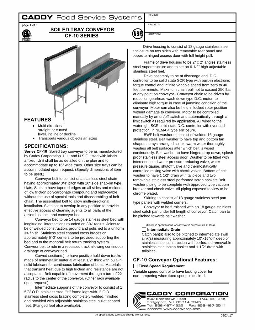
Series CF-10 Soiled tray conveyor to be as manufactured
by Caddy Corporation. U.L. and N.S.F. listed with labels
affixed. Unit shall be as detailed on the plan and to
accommodate up to 16" wide trays. Other size trays can be
accommodated upon request. (Specify dimensions of item
to be used.)
Conveyor belt to consist of a stainless steel chain
having approximately 3/4" pitch with 10" side snap-on type
slats. Slats to have tapered edges on all sides and molded
of low friction polycarbonate compound and replaceable
without the use of special tools and disassembling of belt
chain. The assembled belt to allow multi-directional
installation. Slats not to overlap in any position to provide
effective access of cleaning agents to all parts of the
assembled belt and conveyor bed.
Conveyor bed to be 14 gauge stainless steel bed with
longitudinal intersections rounded on 3/4" radius. Joints to
be of welded construction, ground and polished to a uniform
#4 finish. Stainless steel channel cross braces on
approximately 5'-0" centers to be provided supporting the
bed and to the monorail belt return tracking system.
Conveor belt to ride in a recessed track allowing continuous
drainage of conveyor bed.
Curved section(s) to have positive hold-down tracks
made of nonmetallic material at least 1/2" thick with built-in
solid lubricant for continuous lubrication of belts. Materials
that transmit heat due to high friction and resistance are not
acceptable. Belt capable of movement through a turn of 22"
radius to the center of the conveyor. (Other radii available
upon request.)
Intermediate supports of the conveyor to consist of 1
5/8" O.D. stainless steel "H" frame legs with 1" O.D.
stainless steel cross bracing completely welded, finished
and provided with adjustable stainless steel bullet shaped
feet. (Flanged feet also available).
FEATURES
Multi-directional
straight or curved
level, incline or decline
Transports various objects an sizes
SPECIFICATIONS:
Frame of drive housing to be 2" x 2" angles stainless
steel superstructure and to set on 6-1/2" high adjustable
stainless steel feet.
Drive assembly to be at discharge end. D.C.
controller to be solid state SCR type with built-in electronic
torque control and infinite variable speed from zero to 40
feet per minute. Maximum chain pull not to exceed 250 lbs.
at any point on conveyor. Conveyor chain to be driven by
reduction gearhead wash down type D.C. motor to
eliminate high torque in case of jamming condition of the
conveyor. Motor can also be held in locked rotor position
without damage to conveyor. Motor to be controlled
manually by an on/off switch and automatically through a
limit switch as required by application. All wired to the
watertight SCR solid state D.C. controller with overload
protection, in NEMA 4 type enclosure.
BWF belt washer to consist of welded 16 gauge
stainless steel. Belt washer to have top and bottom fan
shaped sprays arranged so lukewarm water thoroughly
washes all belt surfaces after which belt is wiped
continuously. Belt washer to have hinged drop-down, splash
proof stainless steel access door. Washer to be fitted with
interconnected water pressure reducing valve, water
pressure gauge, shutoff valve and thermostatically
controlled mixing valve with check valves. Bottom of belt
washer to have 1 1/2" drain with tailpiece and two
removable stainless steel perforated scrap baskets.Belt
washer piping to be complete with approved type vacuum
breaker and check valve. All piping exposed to view to be
chrome plated.
Skirting to consist of 18 gauge stainless steel pan
type panels with welded corners.
Conveyor to be furnished with an 18 gauge stainless
steel catch pan under full length of conveyor. Catch pan to
be pitched towards belt washer.
(Continue specifications for conveyor in excess of 20'-0" long)
Intermediate Drain
Catch pan(s) also to be pitched to intermediate swill
sink(s) measuring approximately 10"x16"x4" deep of
stainless steel construction with perforated removable
stainless steel scrap basket and 1-1/2" drain with
tailpiece.
CF-10 Conveyor Optional Features:
Variable speed control to have locking cover for
non-tampering when fixed speed is desired.
Fixed Speed Requirement
CADDY Food Service Systems
509 Sharptown Road P.O. Box 345Bridgeport, NJ 08014-0345Tel: 856-467-4222 Fax: 856-467-5511internet: www.caddycorp.com
CADDY CORPORATION
08/24/17
Drive housing to consist of 18 gauge stainless steel
enclosure on two sides with removable rear panel and
opposite hinged access door with full height pull.

3'-0" 2'-6" 5'-0"
PROJECT:
ITEM NO:
LOCATION:
page 2 of 3
All specifications subject to change without notice
SOILED TRAY CONVEYOR
CF-10 SERIES
CM
Intertek
Optional Accessories Continue:
Operation of belt washer to be controlled by solenoid valve
integrally wired to On/Off switch of conveyor to provide
automatic operation of belt washer while conveyor is
running. A separate On/Off switch to be provided to permit
operation of conveyor without belt washer.
Automatic Water Saver Control for Fresh Water Belt
Washer
BWR belt washer to consist of welded 16 gauge stainless
steel. Belt washer to have top and bottom fan shaped
sprays arranged so lukewarm water thoroughly washes all
belt surfaces after which belt is wiped continuously. Belt
washer to have hinged drop-down, splash proof stainless
steel access door. Washer to be fitted with interconnected
water pressure reducing valve, water pressure gauge,
shutoff valve and thermostatically controlled mixing valve
Belt Washer with Recirculating Water
Drive assembly(s) to be installed at intermediate location(s)
without break in conveyor belt and belt bed.
Intermediate Drive
with check valves. Bottom of belt washer to have 1 1/2"
drain with tailpiece and two removable stainless steel
perforated scrap baskets, and removable constant overflow
standpipe to maintain water level. A pump to be provided to
recirculate water from reservoir through spray nozzles.
Recirculating system to include a removable filter to
facilitate cleaning. Operation of belt washer to be controlled
by solenoid valve integrally wired to On/Off switch of
conveyor to provide automatic operation of belt washer
while conveyor is running. A separate On/Off switch to be
provided to permit operation of conveyor without belt
washer.
Belt washer to be controlled by automatic timer activated by
a push button switch inside belt washer housing in such a
manner that conveyor and belt washer will operate without
interruption for an adjustable cycle of up to 16 minutes.
After completion of wash cycle conveyor is ready for next
start-up.
Timed Belt Washing Cycle (for clean-up operations)
A pump type detergent injector working in conjunction with
the belt washer water supply to be furnished.
Detergent Injector (for maximum sanitation)
Housings for Drive and Belt Washer
Specifying an intermediate drive (or drives) in your conveyor design provides unlimited options to meet architectural,
operational, safety, and efficiency criteria.
U.L. listing of your custom conveyor up to 500 feet long (and more) with one single belt, unbroken by troublesome
transfer points, is standard when specified.
The ability to locate the belt washer separately from the drive, if necessary, to accommodate access and sanitary
consideration, is an important option.
End Drive With Belt Washer
Intermediate Drive Without Belt
Washer
End Drive Without Belt Washer
Intermediate Belt Washer
Intermediate Drive With Belt Washer
CADDY Food Service Systems
509 Sharptown Road P.O. Box 345Bridgeport, NJ 08014-0345Tel: 856-467-4222 Fax: 856-467-5511internet: www.caddycorp.com
CADDY CORPORATION
08/24/17

NOTE: ALL ROUGH-INS TO BE 4"AFF
DESCRIPTION
ROUGH-IN SCHEDULE
1 1/2" I.P.S. WASTE
SYM
A
1/2" I.P.S. HOT WATER
B
1/2" I.P.S. COLD WATER
C
ELECTRICAL CONNECTION
D
A
CB
D
A
FROM 26 to 60 ft.
"E"
OBJECT TRANSPORTED
BED WIDTH
14" X 18" AND 15" X 20"
"E"
16 1/2"
16" X 22" AND 16 1/2" X 22"
18"
20" X 20"
22"
1'-4 1/2"
2'-11"
SPECIFY
3'-1"
SPECIFY
2"
1/2"
PROJECT:
ITEM NO:
LOCATION:
page 3 of 3
All specifications subject to change without notice
SOILED TRAY CONVEYOR
CF-10 SERIES
CM
Intertek
Optional Accessories Continue:
TYPICAL ROUGHING, PLUMBING AND ELECTRICAL DATA
Conveyor has more than two turns.
Conveyor includes sloped section to operate on
more than one horizontal plane.
Conveyor exceeds above dimensions. Location of
turns in relation to drives may allow additional
length per drive.
If tote boxes or dish racks are conveyed.
Conveyors over 20 ft.
long require additional
drain(s) as determined
by application.
NOTE: All roughings from floor should be
stubbed up 4" A.F.F. (All roughings
extending from wall should be 10" A.F.F.
Motor sizes for soiled tray convyors:
STRAIGHT
L-SHAPED
ONE 90°
TURN
1/4 HP up to 25 ft.
1/2 HP 26 to 50 ft.
3/4 HP 51 to 75 ft.
1/4 HP up to 20 ft.
1/2 HP up to 39ft.
3/4 HP up to 56 ft.
U-SHAPED
2 TURNS
1/2 HP up to 25 ft.
3/4 HP 26 to 40 ft.
1/2 HP up to 25 ft.
3/4 HP 26 to 40 ft.
Consult factory if:
Motors available for
120/60 Hz. single phase up to and
including 3/4 hp. Motors 1/2 hp. and 3/4
hp. are also available for 208/220/60 Hz.
single phase.
ELECTRICAL CHARACTERISTICS
Optional Features:
See Accessories Sheet for complete listings
Conveyor Bed Configuration:
See Section View Sheet for complete Detials
Typical Section View at Tray-Drop
CADDY Food Service Systems
509 Sharptown Road P.O. Box 345Bridgeport, NJ 08014-0345Tel: 856-467-4222 Fax: 856-467-5511internet: www.caddycorp.com
CADDY CORPORATION
08/24/17

1'-3 1/2"
2'-11"
SPECIFY
3'-1"
SPECIFY
2"
1/2"
PROJECT:
ITEM NO:
LOCATION:
page 1 of 2
All specifications subject to change without notice
SOILED TRAY CONVEYOR
21-C SERIES
CM
Intertek
Series 21-C Soiled tray conveyor to be as manufactured by
Caddy Corporation. Patent #5,052,548, U.L. and N.S.F.
listed with labels affixed. (5 year limited warrant, i.e.
standard 90-day electrical; 1-year parts and service; 4 year
prorated parts.)
Unit shall be as detailed on the plan and to
accommodate 14"x18" or 15"x20" flat bottom trays. Other
size trays can be accommodated upon request. (Specify
dimensions of trays to be used.)
Conveyor belt to consist of dual 1/2" diameter
Dura-San belting with 1,000 lbs. ultimate tensile strength..
Belting itself is USDA accepted, highly resistant to abrasion,
dirt, oil and most chemicals, maintains tension without
springs, sprockets or links, continuous without ends or
mechanical connection devices. Bands have special
textured surface to reduce friction.
Conveyor to be table top type without concealed
return belts, drain pans or a beltwasher under the conveyor.
Penetrations in the conveyor bed are not allowed. All the
bearings to be stainless steel heavy duty ball type, with
sealed lubrication.
Conveyor bed to be 14 gauge stainless steel bed with
longitudinal intersections rounded on 3/4" radius. Joints to
be of welded construction, ground and polished to a uniform
#4 finish. Stainless steel channel cross braces on
approximately 5'-0" centers to be provided supporting the
bed.
Curved section(s) to have positive hold-down tracks
made of nonmetallic material at least 3/4" thick with built-in
solid lubricant for continuous lubrication of bands. Materials
that transmit heat due to high friction and resistance are not
acceptable. Band capable of movement through a turn of
22" radius to the center of the conveyor. (Other Radii
available upon request.)
FEATURES
Cleanliness
No drip pans
No chains
No beltwasher
Conveyor to be provided with a removable access
panel at tail end providing access to bearings and
adjustment. Drive housing to consist of 18 gauge stainless
steel enclosure on two sides with removable 18 gauge
panel. Frame of drive housing to be 2" x 2" angles stainless
steel superstructure and to set on 6 1/2" high adjustable
stainless steel feet.
Drive assembly to be at discharge end. D.C.
controller to be solid state SCR type with built-in electronic
torque control and infinite variable speed from zero to 40
feet per minute. Conveyor belt to be driven by reduction
gearhead washdown type D.C. motor B.I.S.S.C. certified for
the food industry, free of bacteria trapping surfaces. D.C.
motor to eliminate high torque in case of jamming condition
of the conveyor. Motor to be controlled manually by an
on/off switch and automatically through a limit switch as
required by application. All wired to the watertight controller
with overload protection, in NEMA 4 type enclosure.
SPECIFICATIONS:
No detergent pumps
No concealed belt returns
No hard to reach areas
Optional Features:
See Accessories Sheet for complete listings
Conveyor Bed Configuration:
See Section View Sheet for complete Detials
Typical Section View at Tray-Drop
CADDY Food Service Systems
509 Sharptown Road P.O. Box 345Bridgeport, NJ 08014-0345Tel: 856-467-4222 Fax: 856-467-5511internet: www.caddycorp.com
CADDY CORPORATION
08/24/17
Intermediate supports of the conveyor to consist of 1
5/8" O.D. stainless steel "H" frame legs with 1" O.D.
stainless steel cross bracing completely welded, finished
and provided with adjustable stainless steel bullet shaped
feet. (Flanged feet also available).

NOTE: ALL ROUGH-INS TO BE 4"AFF
DESCRIPTION
ROUGH-IN SCHEDULE
1 1/2" I.P.S. WASTE
SYM
A
B
120v., 60hz., 1ph. 15amps
or 208v., 60hz., 1ph. 15amps
(see motor size below)
AA
B
PROJECT:
ITEM NO:
LOCATION:
page 2 of 2
All specifications subject to change without notice
SOILED TRAY CONVEYOR
21-C SERIES
CM
Intertek
TYPICAL ROUGHING, PLUMBING AND ELECTRICAL DATA
Conveyor has more than two turns.
Conveyor includes sloped section to operate on
more than one horizontal plane.
Conveyor exceeds above dimensions. Location of
turns in relation to drives may allow additional
length per drive.
Conveyors with any type of
turns require additional
drain(s) as determined by
application.
NOTE: All roughings from floor should be
stubbed up 4" A.F.F. (All roughings
extending from wall should be 10" A.F.F.
Motor sizes for soiled tray convyors:
Consult factory if:
STRAIGHT
L-SHAPED
ONE 90°
TURN
1/2 HP up to 30 ft.
3/4 HP up to 45 ft.
1/2 HP up to 20ft.
3/4 HP 21 to 35 ft.
2 TURNS
Conveyors containing
more than one turn may
require two or more
drive locations. Please
contact factory for H.P.
ratings.
CADDY Food Service Systems
509 Sharptown Road P.O. Box 345Bridgeport, NJ 08014-0345Tel: 856-467-4222 Fax: 856-467-5511internet: www.caddycorp.com
CADDY CORPORATION
08/24/17

PROJECT:
ITEM NO:
LOCATION:
page 1 of 3
All specifications subject to change without notice
SOILED TRAY CONVEYOR
MT-12 SERIES
CM
Intertek
Series MT-12 Soiled tray conveyor to be as manufactured
by Caddy Corporation. U.L. and N.S.F. listed with labels
affixed. Unit shall be as detailed on the plan and to normally
accommodate up to 16" wide trays. Other size trays can be
accommodated upon request. (Specify dimensions of item
to be used.)
Conveyor belt to consist of low friction polycarbonate
compound and replaceable without the use of special tools
and disassembling of entire belt . The assembled belt to
allow multi-directional installation. Plastic mesh not to
overlap in any position to provide effective access of
cleaning agents to all parts of the assembled belt and
conveyor bed.
Conveyor bed to be 14 gauge stainless steel bed with
longitudinal intersections rounded on 3/4" radius. Joints to
be of welded construction, ground and polished to a uniform
#4 finish. Stainless steel channel cross braces on
approximately 5'-0" centers to be provided supporting the
bed and side track. Conveor belt to ride in a recessed
self-lubricating track allowing continuous drainage of
conveyor bed.
Curved section(s) to have positive hold-down tracks
made of nonmetallic material at least 1/2" thick with built-in
solid lubricant for continuous lubrication of belts. Materials
that transmit heat due to high friction and resistance are not
acceptable. Belt capable of movement through a turn of 22"
radius to the center of the conveyor. (Other radii available
upon request.)
Intermediate supports of the conveyor to consist of 1
5/8" O.D. stainless steel "H" frame legs with 1" O.D.
stainless steel cross bracing completely welded, finished
and provided with adjustable stainless steel bullet shaped
feet. (Flanged feet also available).
Drive housing to consist of 18 gauge stainless steel
enclosure on two sides with removable rear panel and
opposite hinged access door with full height pull.
FEATURES
Multi-directional, straight or curved, level or inclined
Transports various objects an sizes (Tray or Trayless)
Various width belts: 6", 12", 15", 18", 24", or 30"
SPECIFICATIONS:
Frame of drive housing to be 2" x 2" angles stainless steel
superstructure and to set on 6-1/2" high adjustable stainless
steel feet.
Drive assembly to be at discharge end. D.C.
controller to be solid state SCR type with built-in electronic
torque control and infinite variable speed from zero to 40
feet per minute. Maximum chain pull not to exceed 250 lbs.
at any point on conveyor. Conveyor chain to be driven by
reduction gearhead wash down type D.C. motor to
eliminate high torque in case of jamming condition of the
conveyor. Motor can also be held in locked rotor position
without damage to conveyor. Motor to be controlled
manually by an on/off switch and automatically through a
limit switch as required by application. All wired to the
watertight SCR solid state D.C. controller with overload
protection, in NEMA 4 type enclosure.
BWF belt washer to consist of welded 16 gauge
stainless steel. Belt washer to have top and bottom fan
shaped sprays arranged so lukewarm water thoroughly
washes all belt surfaces after which belt is wiped
continuously. Belt washer to have hinged drop-down, splash
proof stainless steel access door. Washer to be fitted with
interconnected water pressure reducing valve, water
pressure gauge, shutoff valve and thermostatically
controlled mixing valve with check valves. Bottom of belt
washer to have 1 1/2" drain with tailpiece and two
removable stainless steel perforated scrap baskets.Belt
washer piping to be complete with approved type vacuum
breaker and check valve. All piping exposed to view to be
chrome plated.
Skirting to consist of 18 gauge stainless steel pan
type panels with welded corners.
Conveyor to be furnished with an 18 gauge stainless
steel catch pan under full length of conveyor. Catch pan to
be pitched towards belt washer.
(Continue specifications for conveyor in excess of 20'-0" long)
Intermediate Drain
Catch pan(s) also to be pitched to intermediate swill
sink(s) measuring approximately 10"x16"x4" deep of
stainless steel construction with perforated removable
stainless steel scrap basket and 1-1/2" drain with
tailpiece.
MT-12 Conveyor Optional Features:
Variable speed control to have locking cover for
non-tampering when fixed speed is desired.
Fixed Speed Requirement
CADDY Food Service Systems
509 Sharptown Road P.O. Box 345Bridgeport, NJ 08014-0345Tel: 856-467-4222 Fax: 856-467-5511internet: www.caddycorp.com
CADDY CORPORATION
08/24/17

3'-0" 2'-6" 5'-0"
PROJECT:
ITEM NO:
LOCATION:
page 2 of 3
All specifications subject to change without notice
SOILED TRAY CONVEYOR
MT-12 SERIES
CM
Intertek
Optional Accessories Continue:
Operation of belt washer to be controlled by solenoid valve
integrally wired to On/Off switch of conveyor to provide
automatic operation of belt washer while conveyor is
running. A separate On/Off switch to be provided to permit
operation of conveyor without belt washer.
Automatic Water Saver Control for Fresh Water Belt
Washer
BWR belt washer to consist of welded 16 gauge stainless
steel. Belt washer to have top and bottom fan shaped
sprays arranged so lukewarm water thoroughly washes all
belt surfaces after which belt is wiped continuously. Belt
washer to have hinged drop-down, splash proof stainless
steel access door. Washer to be fitted with interconnected
water pressure reducing valve, water pressure gauge,
shutoff valve and thermostatically controlled mixing valve
Belt Washer with Recirculating Water
Drive assembly(s) to be installed at intermediate location(s)
without break in conveyor belt and belt bed.
Intermediate Drive
with check valves. Bottom of belt washer to have 1 1/2"
drain with tailpiece and two removable stainless steel
perforated scrap baskets, and removable constant overflow
standpipe to maintain water level. A pump to be provided to
recirculate water from reservoir through spray nozzles.
Recirculating system to include a removable filter to
facilitate cleaning. Operation of belt washer to be controlled
by solenoid valve integrally wired to On/Off switch of
conveyor to provide automatic operation of belt washer
while conveyor is running. A separate On/Off switch to be
provided to permit operation of conveyor without belt
washer.
Belt washer to be controlled by automatic timer activated by
a push button switch inside belt washer housing in such a
manner that conveyor and belt washer will operate without
interruption for an adjustable cycle of up to 16 minutes.
After completion of wash cycle conveyor is ready for next
start-up.
Timed Belt Washing Cycle (for clean-up operations)
A pump type detergent injector working in conjunction with
the belt washer water supply to be furnished.
Detergent Injector (for maximum sanitation)
Housings for Drive and Belt Washer
Specifying an intermediate drive (or drives) in your conveyor design provides unlimited options to meet architectural,
operational, safety, and efficiency criteria.
U.L. listing of your custom conveyor up to 500 feet long (and more) with one single belt, unbroken by troublesome
transfer points, is standard when specified.
The ability to locate the belt washer separately from the drive, if necessary, to accommodate access and sanitary
consideration, is an important option.
End Drive With Belt Washer
Intermediate Drive Without Belt
Washer
End Drive Without Belt Washer
Intermediate Belt Washer
Intermediate Drive With Belt Washer
CADDY Food Service Systems
509 Sharptown Road P.O. Box 345Bridgeport, NJ 08014-0345Tel: 856-467-4222 Fax: 856-467-5511internet: www.caddycorp.com
CADDY CORPORATION
08/24/17

NOTE: ALL ROUGH-INS TO BE 4"AFF
DESCRIPTION
ROUGH-IN SCHEDULE
1 1/2" I.P.S. WASTE
SYM
A
1/2" I.P.S. HOT WATER
B
1/2" I.P.S. COLD WATER
C
ELECTRICAL CONNECTION
D
A
CB
D
A
FROM 26 to 60 ft.
"E"
OBJECT TRANSPORTED
BED WIDTH
14" X 18" AND 15" X 20"
"E"
16 1/2"
16" X 22" AND 16 1/2" X 22"
18"
20" X 20"
22"
2'-11"
SPECIFY
1'-3 1/2"
3'-1"
SPECIFY
PROJECT:
ITEM NO:
LOCATION:
page 3 of 3
All specifications subject to change without notice
CM
Intertek
Optional Accessories Continue:
TYPICAL ROUGHING, PLUMBING AND ELECTRICAL DATA
Conveyor has more than two turns.
Conveyor includes sloped section to operate on
more than one horizontal plane.
Conveyor exceeds above dimensions. Location of
turns in relation to drives may allow additional
length per drive.
If tote boxes or dish racks are conveyed.
Conveyors over 20 ft.
long require additional
drain(s) as determined
by application.
NOTE: All roughings from floor should be
stubbed up 4" A.F.F. (All roughings
extending from wall should be 10" A.F.F.
Motor sizes for soiled tray convyors:
STRAIGHT
L-SHAPED
ONE 90°
TURN
1/4 HP up to 25 ft.
1/2 HP 26 to 50 ft.
3/4 HP 51 to 75 ft.
1/4 HP up to 20 ft.
1/2 HP up to 39ft.
3/4 HP up to 56 ft.
U-SHAPED
2 TURNS
1/2 HP up to 25 ft.
3/4 HP 26 to 40 ft.
1/2 HP up to 25 ft.
3/4 HP 26 to 40 ft.
Consult factory if:
Motors available for
120/60 Hz. single phase up to and
including 3/4 hp. Motors 1/2 hp. and 3/4
hp. are also available for 208/220/60 Hz.
single phase.
ELECTRICAL CHARACTERISTICS
Optional Features:
See Accessories Sheet for complete listings
Conveyor Bed Configuration:
See Section View Sheet for complete Detials
Typical Section View at Tray-Drop
CADDY Food Service Systems
509 Sharptown Road P.O. Box 345Bridgeport, NJ 08014-0345Tel: 856-467-4222 Fax: 856-467-5511internet: www.caddycorp.com
CADDY CORPORATION
08/24/17
SOILED TRAY CONVEYOR
MT-12 SERIES

5'-6"
MIN.
5'-4 1/2"
MIN.
2'-6"
RADIUS
C
L
3'-0"
HOUSING
2"
STRAIGHT
3'-3 3/4"
6'-3 1/2"
MIN.
3'-0"
HOUSING
2"
STRAIGHT
2'-8 1/4"
1'-10"
RADIUS
C
L
PROJECT:
ITEM NO:
LOCATION:
page 1 of 1
All specifications subject to change without notice
SOILED TRAY CONVEYOR
Conveyor Bed Configuration
CM
Intertek
Conveyor Bed Configuration:
Tray drop sill with 10" high splash
adjacent to walls.
Type A
Free standing section(s) with
channel rim curbing(s) on both
sides.
Type B
10" high splash adjacent to wall(s)
and channel rim front curbing.
Type C
10" high splash between two walls
Type D
10" high splash adjacent to wall(s)
and rolled rim front curbing
Type E
Discharge from bed directly onto
dish table
Type F
Minimum Bed Configuration:
21-C Double Turn CF-10 Double Turn CF-10 Turn and Housing
CADDY Food Service Systems
509 Sharptown Road P.O. Box 345Bridgeport, NJ 08014-0345Tel: 856-467-4222 Fax: 856-467-5511internet: www.caddycorp.com
CADDY CORPORATION
08/24/17
MT-12 Double Turn
MT-12 Turn and Housing
2"
1/2"
SPECIFY
SPECIFY
BED HEIGHT
A.F.F.
HIGH SPLASH
2"
1/2"
2"
SPECIFY
SPECIFY2"
CENTER GUIDE
REQUIRED FOR
MODEL CC ONLY
OPENING
OPENING
+ 12"
SPECIFY
PROJECT:
ITEM NO:
LOCATION:
All specifications subject to change without notice
CM
Intertek
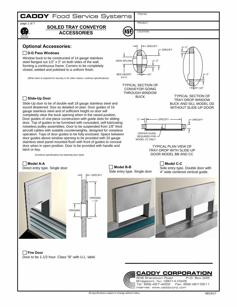
Window buck to be constructed of 14 gauge stainless
steel flanged out 1/2" x 2" on both sides of the wall,
forming a continuous frame. Corners to be completely
closed, welded and polished to a uniform finish.
Optional Accessories:
D-D Pass Windows
page 1 of 7
SOILED TRAY CONVEYOR
ACCESSORIES
(When door is required for security or for other reason, continue specifications)
Slide-Up door to be of double wall 18 gauge stainless steel and
sound deadened. Size as detailed on plan. Door guides of 16
gauge stainless steel and of sufficient height so door will
completely clear the buck opening when in the raised position.
Door guides of one-piece construction with guide slots for sliding
door. Top of guides to be furnished with concealed, self-lubricating
noiseless pulley assemblies. Door to be suspended from 1/8" thick
aircraft cables with suitable counterweights, designed for noiseless
operation. Tops of door guides to be fully enclosed. Space between
door guides above window opening to be provided with 20 gauge
stainless steel panel mounted flush with front of guides to conceal
door when in open position. Door to be provided with handle and
latch or key.
Slide-Up Door
TYPICAL SECTION OF
CONVEYOR GOING
THROUGH WINDOW
BUCK
TYPICAL SECTION OF
TRAY-DROP WINDOW
BUCK AND SILL MODEL DD
WITHOUT SLIDE-UP DOOR
(Continue specifications by selecting door style)
Model A-A
Direct entry type. Single door
Model B-B
Side entry type. Single door
TYPICAL PLAN VIEW OF
TRAY-DROP WITH SLIDE-UP
DOOR MODEL BB AND CC
Model C-C
Side entry type. Double door with
4" wide centered vertical guide.
Fire Door
Door to be 1-1/2 hour. Class "B" with U.L. label
CADDY Food Service Systems
509 Sharptown Road P.O. Box 345Bridgeport, NJ 08014-0345Tel: 856-467-4222 Fax: 856-467-5511internet: www.caddycorp.com
CADDY CORPORATION
08/24/17

LIGHT
FIXTURE
4"
LAMINATED
PANEL
KICK PLATE
3"
1 1/2"
45° TURN UP
SILVER SAVER
ROD
FLUSHING
DEVISE
DISPOSER
SINK
1'-4"
1'-10"
1"
PROJECT:
ITEM NO:
LOCATION:
All specifications subject to change without notice
CM
Intertek
Optional Accessories Continue:
page 2 of 7
Baffle to extend 2" above top of
window opening with full enclosure at
both ends, top and rear. End enclosure
next to dish room to end 12" above the
conveyor bed. The entire sight and
sound baffle to be of double wall 18
gauge stainless steel construction with
sound deadening filler throughout.
Rear of sight and sound baffle to be
fitted with double wall removable
access panel. The top to have a light
fixture.
Sight and Sound Baffle
Skirting at tray drop to consist of
removable 3/4" thick plywood
panels with waterproof backing
and plastic lamination (color or
pattern to be selected later) on
front and all edges. This section
of conveyor to be set on 6" high
recessed 14 gauge stainless steel
toe base.
Full Height Skirting
Table to be provided. Table and conveyor bed to be
coordinated as one entire homogeneous unit to reduce field
welding. Dish table to be constructed of 14 gauge stainless
steel with all exposed edges finished in a 3" high curbing
with 1 1/2" diameter 180 degree rolled rim with corners
bullnosed. All corners to be rounded horizontally and
vertically forming a cove at intersection. Joints to be
continuously welded, ground and polished to a #4 finish to
appear as one continuous surface free of buckles and weld
Soiled Dish Table
marks. Next to conveyor bed,
the table surface is to be sloped
up at a 45 degree angle. Top to
be cross braced with 14 gauge
stainless steel channel stiffeners
welded to the underside. Cross
stiffeners to be at leg assembly
stations on approximately 5'-0"
centers. Legs to be constructed
as specified for the conveyor
with cross bracing as required to
provide a rigid assembly.
dimensioned on drawing. Sink to be made of 14 gauge
stainless steel with all corners coved. Seam between sink
and top to be continuously welded. Where trough meets
disposer sink station it is to be fitted with a silver saver barrier
consisting of a stainless steel horizontal rod properly spaced
of prevent silverware from entering the disposer. (Disposer
adapter ring furnished by manufacture of the disposer.) Seam
between disposer and adapter ring and sink bottom to be
continuously welded, ground smooth and polished.
Sloped lower racking shelf to be constructed of 14 gauge
stainless steel with shelf surface measuring 22" in width and
sloped up toward rear at a 40 degree angle. Shelf to to have
2" high curbing at front. The rim of front curbing to have 1"
wide channel facing rear to provided space inside for liquid
accumulation. Rear and ends of shelf to have 2" high
vertical risers. Lower edge of shelf to have drain holes. Shelf
to be attached to 12 gauge stainless steel cantilever
brackets. Brackets to consist of a triangular shaped plate
and a stainless steel angle welded to the underside of shelf.
Plates and angles to have rows of conforming slots to permit
front to back adjustment of shelf. Each bracket to be
provided with two stainless steel truss head bolts and
stainless steel nuts.
Double Overhead Racking and Storage Shelves
A 16" wide adjustable, flat
upper shelf is also to be provided
for storage of empty dishwasher
racks. Shelf to have turned down
channel edge at front and 2" high
riser at rear. Both ends to be
fitted with 16" high "U" shaped
rack supports made of 3/8"
diameter stainless steel rod.
Scrapping Trough
Trough to be made of the same material as adjoining dish
table and constructed integrally with the same. Trough bottom
to be pitched to a disposal unit and to have corners coved to
a 3/4" radius. Where the trough intersects disposer sink, it is
to be continuously welded. Weld to be ground smooth and
polished to a uniform finish Trough bottom to be provided with
water flushing devises to simplify flushing of entire trough
bottom. The disposer sink station to be as
SOILED TRAY CONVEYOR
ACCESSORIES
CADDY Food Service Systems
509 Sharptown Road P.O. Box 345Bridgeport, NJ 08014-0345Tel: 856-467-4222 Fax: 856-467-5511internet: www.caddycorp.com
CADDY CORPORATION
08/24/17

1'-10"
1"
1'-4"
12 GA. STN. STL.
WALL MOUNTED ANGLE
2'-6"
1'-6"
TUBULAR
UPRIGHT
CANTILEVER
BRACKET
PROJECT:
ITEM NO:
LOCATION:
All specifications subject to change without notice
CM
Intertek
Optional Accessories Continue:
page 3 of 7
Plates and angles to have rows of
conforming slots to permit front to back
adjustment of shelf. Each bracket to be
provided with two stainless steel truss
head bolts and stainless steel cap nuts.
Single Overhead Racking Shelf
Shelf to be supported by 1 5/8" O.D.
stainless steel tubular uprights which are
integrally attached to the leg assembly.
Uprights to be fitted with stainless steel
sleeves to which shelf brackets are
welded. Sleeves to have set screws to
facilitates vertical adjustment of shelf.
Tubular Mounted Shelf(s)
Flat storage shelf to be constructed of 14 gauge stainless
steel with shelf surface measuring 16" wide. Shelf to have
turned down channel edge at front and 2" high riser at rear.
Both ends to be fitted with 16" high "U" shaped rack
supports made of 3/8" diameter stainless steel rod. Shelf to
be attached to 12 gauge stainless steel cantilever brackets
Single Overhead Storage Shelf
Sloped racking shelf to be constructed of 14 gauge stainless
steel with shelf surface measuring 22" in width and sloped
up toward rear at a 40 degree angle. Shelf to have 2" high
curbing at front. The rim of front curbing to have 1" wide
channel facing rear to provide space inside for liquid
accumulation. Rear and ends of shelf to have 2" high
vertical risers. Lower edge of shelf to have drain holes. Shelf
to be attached to 12 gauge stainless steel cantilever
brackets. Brackets to consist of a a triangular shaped plate
and a stainless steel angle welded to the underside of shelf.
Brackets to be welded to the underside
of shelf. Plates and angles to have rows
of conforming slots to permit front to
back adjustment of shelf. Each bracket
to be provided with two stainless steel
truss head bolts and stainless steel nuts.
Shelf to be supported by 1 1/2" x 1 1/2" x 1/8" thick stainless
steel angles. Angles to measure 18" long for single shelf and
30" long for double shelves. One leg of each angle which
Wall Mounted Shelf(s)
protrudes from wall and to
which shelf bracket is
attached to be provided with
a row of bolt holes over full
length of the angle and
spaced 1" apart to facilitate
vertical adjustment of shelf.
Bracket to be fastened to
angles with stainless steel
bolts and nuts.
Single
Shelf
Double
Shelf
Brackets to be 12 gauge polished
stainless steel spaced as required by
application. (6'-0" maximum)
Cantilever Wall Supports (in lieu of legs)
Electronic, receiver-transmitter photo electric cell type switch
assembly installed and located on the conveyor bed to
operate as a monitor for trays passing on the conveyor belts
at a predetermined location. Conveyor belts stop when a
tray sits for a predetermined amount of time in front of the
eye, and restart when the tray is removed. Switch to be
activated by tray passing through eye's beam. Control to be
integrally wired into main circuitry of conveyor drive
mechanism eliminating additional wiring work on the part of
the electrical contractor making final connection to the
conveyor system.
Time Delay Limit Switch
Electronic, receiver-transmitter photo electric cell type switch
assembly installed and located on the conveyor bed to
operate as a monitor for trays passing on the conveyor belts
at a predetermined location. Conveyor belts stop when a
tray breaks the light beam, and restart when the tray is
removed. Switch to be activated by tray passing through
eye's beam. Control to be integrally wired into main circuitry
of conveyor drive mechanism eliminating additional wiring
work on the part of the electrical contractor making final
connection to the conveyor system.
End Limit Switch
Trays to electronically transfer from traydrop conveyor to
accumulation conveyor and accumulate the entire length of
the accumulation conveyor. At this point a remote
audio-visual indicator will advise that the system is full and
ready for scrapping.
Accumulation Feature
SOILED TRAY CONVEYOR
ACCESSORIES
CADDY Food Service Systems
509 Sharptown Road P.O. Box 345Bridgeport, NJ 08014-0345Tel: 856-467-4222 Fax: 856-467-5511internet: www.caddycorp.com
CADDY CORPORATION
08/24/17
PROJECT:
ITEM NO:
LOCATION:
All specifications subject to change without notice
CM
Intertek
Optional Accessories Continue:
page 4 of 7
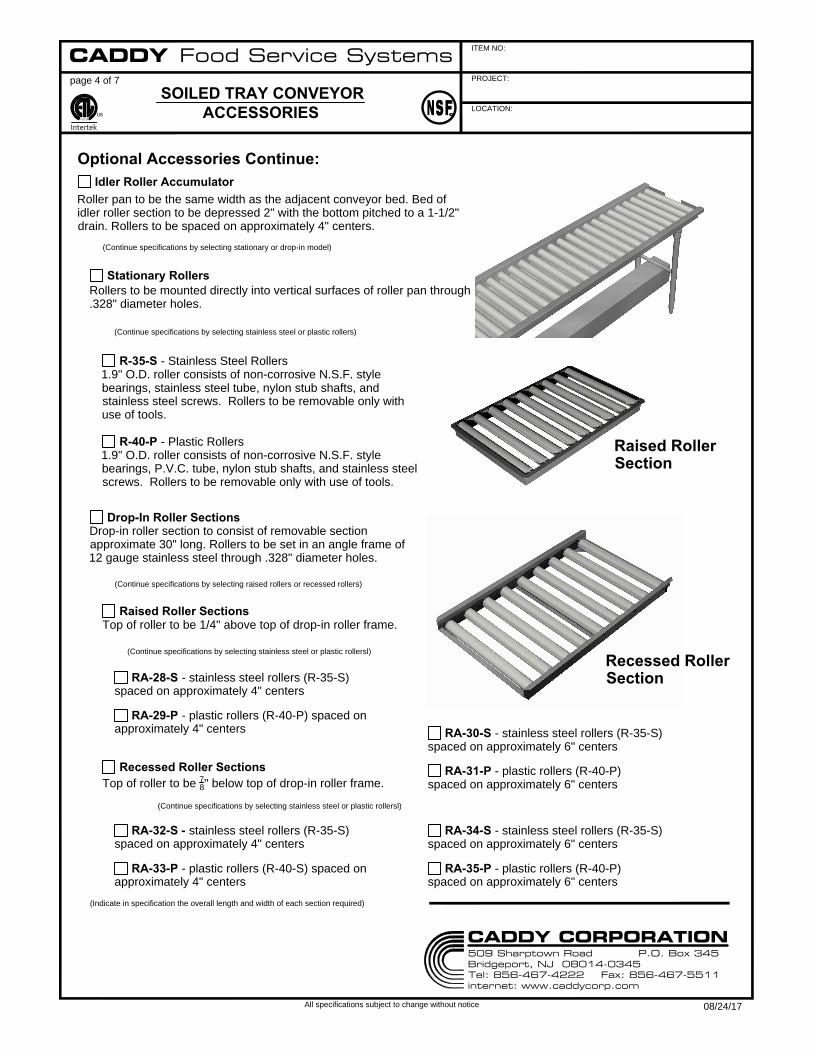
Roller pan to be the same width as the adjacent conveyor bed. Bed of
idler roller section to be depressed 2" with the bottom pitched to a 1-1/2"
drain. Rollers to be spaced on approximately 4" centers.
Idler Roller Accumulator
(Continue specifications by selecting stationary or drop-in model)
Stationary Rollers
Rollers to be mounted directly into vertical surfaces of roller pan through
.328" diameter holes.
R-35-S - Stainless Steel Rollers
1.9" O.D. roller consists of non-corrosive N.S.F. style
bearings, stainless steel tube, nylon stub shafts, and
stainless steel screws. Rollers to be removable only with
use of tools.
R-40-P - Plastic Rollers
1.9" O.D. roller consists of non-corrosive N.S.F. style
bearings, P.V.C. tube, nylon stub shafts, and stainless steel
screws. Rollers to be removable only with use of tools.
Drop-In Roller Sections
Drop-in roller section to consist of removable section
approximate 30" long. Rollers to be set in an angle frame of
12 gauge stainless steel through .328" diameter holes.
(Continue specifications by selecting stainless steel or plastic rollersl)
RA-28-S - stainless steel rollers (R-35-S)
spaced on approximately 4" centers
Raised Roller Sections
Top of roller to be 1/4" above top of drop-in roller frame.
(Continue specifications by selecting raised rollers or recessed rollers)
RA-29-P - plastic rollers (R-40-P) spaced on
approximately 4" centers
RA-30-S - stainless steel rollers (R-35-S)
spaced on approximately 6" centers
RA-31-P - plastic rollers (R-40-P)
spaced on approximately 6" centers
(Continue specifications by selecting stainless steel or plastic rollersl)
RA-32-S - stainless steel rollers (R-35-S)
spaced on approximately 4" centers
RA-33-P - plastic rollers (R-40-S) spaced on
approximately 4" centers
RA-34-S - stainless steel rollers (R-35-S)
spaced on approximately 6" centers
RA-35-P - plastic rollers (R-40-P)
spaced on approximately 6" centers
(Indicate in specification the overall length and width of each section required)
SOILED TRAY CONVEYOR
ACCESSORIES
CADDY Food Service Systems
509 Sharptown Road P.O. Box 345Bridgeport, NJ 08014-0345Tel: 856-467-4222 Fax: 856-467-5511internet: www.caddycorp.com
CADDY CORPORATION
08/24/17
(Continue specifications by selecting stainless steel or plastic rollers)
Recessed Roller Sections
Top of roller to be
7
8
" below top of drop-in roller frame.
Raised Roller
Section
Recessed Roller
Section
1'-10"
BED WIDTH
3'-3"
MIN.
FOR A
20" X 20"
RACK
1'-10"
BED WIDTH
3'-3"
MIN.
FOR A
20" X 20"
RACK
(2) 45° TURN
DROP-IN SECTIONS
2"
1"
PROJECT:
ITEM NO:
LOCATION:
All specifications subject to change without notice
CM
Intertek
Optional Accessories Continue:
page 5 of 7
(Continue specifications by selecting stainless steel or plastic rollersl)
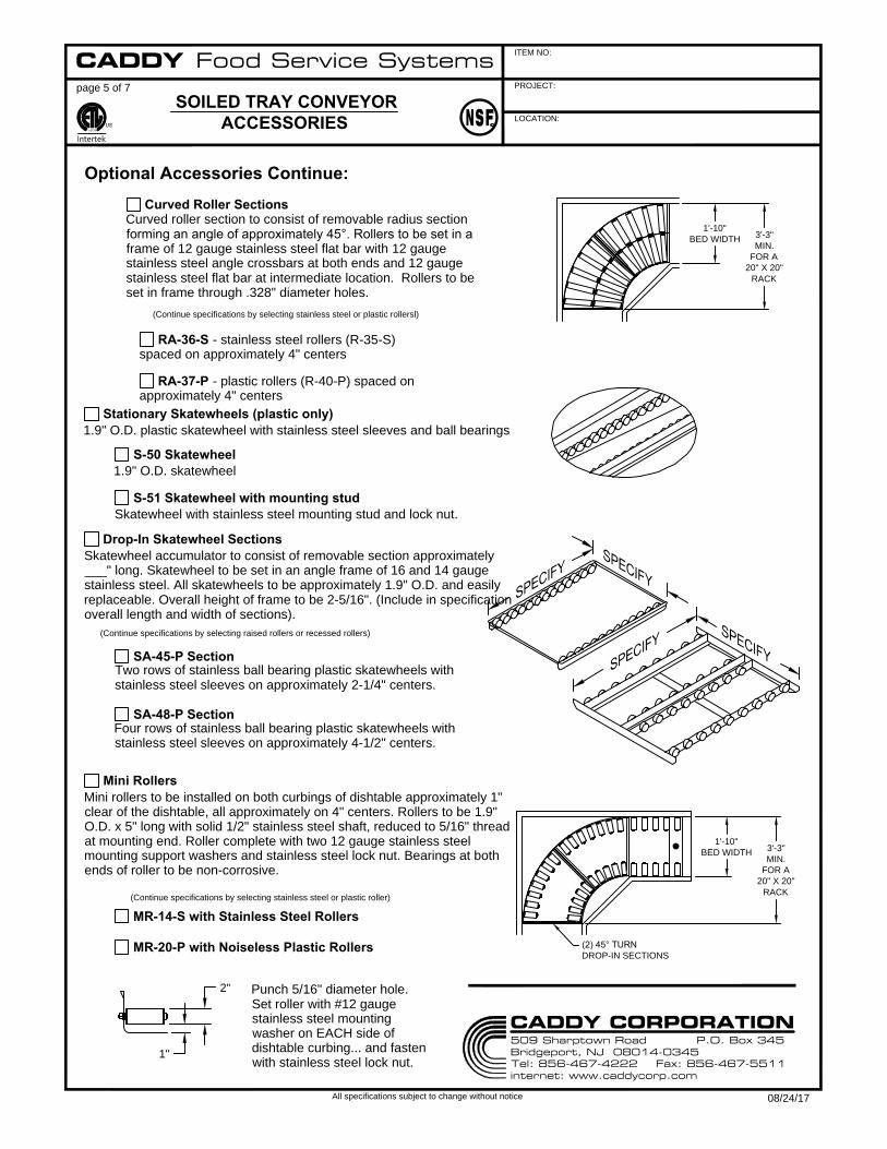
Curved Roller Sections
Curved roller section to consist of removable radius section
forming an angle of approximately 45°. Rollers to be set in a
frame of 12 gauge stainless steel flat bar with 12 gauge
stainless steel angle crossbars at both ends and 12 gauge
stainless steel flat bar at intermediate location. Rollers to be
set in frame through .328" diameter holes.
Stationary Skatewheels (plastic only)
1.9" O.D. plastic skatewheel with stainless steel sleeves and ball bearings
S-50 Skatewheel
1.9" O.D. skatewheel
S-51 Skatewheel with mounting stud
Skatewheel with stainless steel mounting stud and lock nut.
Mini Rollers
Mini rollers to be installed on both curbings of dishtable approximately 1"
clear of the dishtable, all approximately on 4" centers. Rollers to be 1.9"
O.D. x 5" long with solid 1/2" stainless steel shaft, reduced to 5/16" thread
at mounting end. Roller complete with two 12 gauge stainless steel
mounting support washers and stainless steel lock nut. Bearings at both
ends of roller to be non-corrosive.
(Continue specifications by selecting stainless steel or plastic roller)
MR-14-S with Stainless Steel Rollers
MR-20-P with Noiseless Plastic Rollers
Drop-In Skatewheel Sections
Skatewheel accumulator to consist of removable section approximately
___" long. Skatewheel to be set in an angle frame of 16 and 14 gauge
stainless steel. All skatewheels to be approximately 1.9" O.D. and easily
replaceable. Overall height of frame to be 2-5/16". (Include in specification
overall length and width of sections).
SA-45-P Section
(Continue specifications by selecting raised rollers or recessed rollers)
Two rows of stainless ball bearing plastic skatewheels with
stainless steel sleeves on approximately 2-1/4" centers.
SA-48-P Section
Four rows of stainless ball bearing plastic skatewheels with
stainless steel sleeves on approximately 4-1/2" centers.
Punch 5/16" diameter hole.
Set roller with #12 gauge
stainless steel mounting
washer on EACH side of
dishtable curbing... and fasten
with stainless steel lock nut.
SOILED TRAY CONVEYOR
ACCESSORIES
CADDY Food Service Systems
509 Sharptown Road P.O. Box 345Bridgeport, NJ 08014-0345Tel: 856-467-4222 Fax: 856-467-5511internet: www.caddycorp.com
CADDY CORPORATION
08/24/17
RA-36-S - stainless steel rollers (R-35-S)
spaced on approximately 4" centers
RA-37-P - plastic rollers (R-40-P) spaced on
approximately 4" centers

LOADED
POSITION
CART LOADED
SWITCH
CART IN-PLACE
SWITCH
SKATEWHEEL ASS'Y
SCANNING SWITCH
LOADED
POSITION
CART LOADED
SWITCH
CART IN-PLACE
SWITCH
POWER
TRAY STACKER
SCANNING SWITCH
PROJECT:
ITEM NO:
LOCATION:
All specifications subject to change without notice
CM
Intertek
Powered Tray Stacker
page 6 of 7
Tray stacker to be installed at discharge end of conveyor. Tray stacker bed to be of 14
gauge stainless steel, type 304 seamlessly formed, welded, ground and polished to
match the finish of the conveyor. Removable 14 gauge stainless steel inset angle
frame to have two rows of skatewheels with stainless steel ball bearings mounted on
2" centers. Width of tray stacker to accommodate 14" to 15" wide trays. Discharge
end of the conveyor to be fitted with suitable guide clips to secure a tray stacker cart
in proper loading position. Tray stacker to include a scanning switch at the end of the
belt to allow only empty trays to pass and two monitoring, independently operating
limit switches. One switch to close circuit to conveyor power drive when a tray
stacker cart is in the proper stacking position and open circuit when cart is removed.
Second switch to stop conveyor when stacking cart has been loaded to maximum
capacity. All switches to be interwired to the conveyor drive so that only one final
electrical connection is required in the field.
Gravity Tray Stacker
Tray stacker to be 8" long and installed at discharge end of conveyor. Tray
stacker bed to be of 14 gauge stainless steel, type 301 seamlessly formed,
welded, ground and polished to match the finish of the conveyor. Stacker to
have two plastic powered rollers geared to accelerate tray discharge. Rollers to
be ball bearing type. Housing to have removable stainless steel access panel
and clearance under rollers for easy cleaning and to be powered by a fractional
horsepower motor with concealed drive. Motor to be interwired with drive motor
of conveyor, with by-pass switch to allow deactivation of tray stacker. Tray
stacker to accommodate 14" or 15" wide trays. Discharge end of the conveyor
to be fitted with suitable guide clips to secure a tray stacker cart in proper
loading position. Tray stacker to include a scanning switch at the end of the belt
to allow only empty trays to pass and two monitoring, independently operating
limit switches. One switch to close circuit to conveyor power drive when a tray
stacker cart is in the proper stacking position and open circuit when cart is
removed. Second switch to stop conveyor when stacking cart has been loaded
to maximum capacity. All switches to be interwired to the conveyor drive so that
only one final electrical connection is required in the field.
Optional Accessories Continue:
Automatic Stacking Limit Switches
Tray stacker (power or gravity model) to be fitted with two monitoring, independently operating limit
switches. One switch to close circuit to conveyor power drive when tray stacker truck is in proper stacking
position and open circuit when truck is removed. Second switch to stop conveyor when Caddymagic
stacking truck has been loaded to maximum capacity. Both switches to be interwired to conveyor drive so
that only one final electrical connection is required in the field.
Tray Stacker Optional Features
By-Pass Limit Switch
Switch to de-activate automatic stacking limit switches.
SOILED TRAY CONVEYOR
ACCESSORIES
CADDY Food Service Systems
509 Sharptown Road P.O. Box 345Bridgeport, NJ 08014-0345Tel: 856-467-4222 Fax: 856-467-5511internet: www.caddycorp.com
CADDY CORPORATION
08/24/17

2"
5 1/4"
PROJECT:
ITEM NO:
LOCATION:
All specifications subject to change without notice
CM
Intertek
page 7 of 7
Mobile bridge to be constructed of 14 gauge stainless steel type 304
seamlessly formed, welded, ground and polished to match the finish of the
conveyor. Size to be as required. Three sides of bridge to have 1-1/2" diameter
180 degree rolled rims. Fourth side to be turned down over raised edge of
scrapping trough. Bridge to be supported by 1-5/8" O.D. stainless steel legs
with 1" O.D. stainless steel "H" railing completely welded and finished, and
provided with 5" diameter casters with polyurethane tires and foot brakes.
Stainless steel leg sleeves with set screws to facilitate vertical adjustment to be
welded to underside of bridge.
Mobile Bridge
Optional Accessories Continue:
Removable bridge to be constructed of 14 gauge stainless steel type 304
seamlessly formed, welded, ground and polished to match the finish of the
conveyor. Size to be as required. Two sides of bridge to have 1-1/2" diameter
180 degree rolled rims. Ends to be turned down over both supporting edges.
Removable Bridge
Sink to be 22" x 22" x 8" deep inside, constructed of 14 gauge stainless
steel, with all interior corners coved and provided with 1-1/2" diameter 180
degree rolled rims on four sides ending in bullnosed corners. Sink bottom to
be creased to a 1-1/2" twist handle waste outlet set into recessed
die-stamped opening. Sink to have 10" legs made of 1-5/8" O.D. stainless
steel tubing welded to be underside of the sink and furnished with 5"
diameter casters with polyurethane tires and foot brakes.
T-101 Silver Soak Sink
Chute to be constructed of 14 gauge stainless steel flanged out 2" on the
dining room side of the wall, forming continuous frame. Corners to be
completely closed, welded and polished to a uniform finish.
Recycling Chute
Enclosure to be stainless steel in lieu of standard NEMA
epoxy painted steel.
NEMA 4X Electrical Enclosure
Silver sorting caddy to be 42" long x 26-1/2" wide x 35-7/8"
high to table surface. Top of 14 gauge stainless steel turned
up 2" on three sides with corners welded. Attendant's side of
the table to have integrally constructed trough 4" deep x
4-1/4" wide to receive cutlery containers. Front of the trough
to have a channel rim. Legs of 1-1/4" square stainless steel
tubing, with three set of #14 gauge stainless steel angles
spaced on 6" centers to receive 20"x20" silver racks. The
unit to be provided with 5" polyurethane tires, two with foot
brakes.
T-239 Silver Sorting Caddy
T-305 Bulk Silver Caddy
See Bulk Silver Caddy cutsheet
for specifications
SOILED TRAY CONVEYOR
ACCESSORIES
T-407 Bulk Silver Caddy
See Bulk Silver Caddy cutsheet
for specifications
T-402 Tray & Silver Caddy
See Tray & Silver Caddy
cutsheet for specifications
T-301 Tray & Silver Caddy
See Tray & Silver Caddy
cutsheet for specifications
MODEL T-239
CADDY Food Service Systems
509 Sharptown Road P.O. Box 345Bridgeport, NJ 08014-0345Tel: 856-467-4222 Fax: 856-467-5511internet: www.caddycorp.com
CADDY CORPORATION
08/24/17
2"
1/2"
2"
SPECIFY
4"
LAMINATED
PANEL
KICK PLATE
PROJECT:
ITEM NO:
LOCATION:
page 1 of 2
All specifications subject to change without notice
SOILED TRAY CONVEYOR
STA-R
CM
Intertek
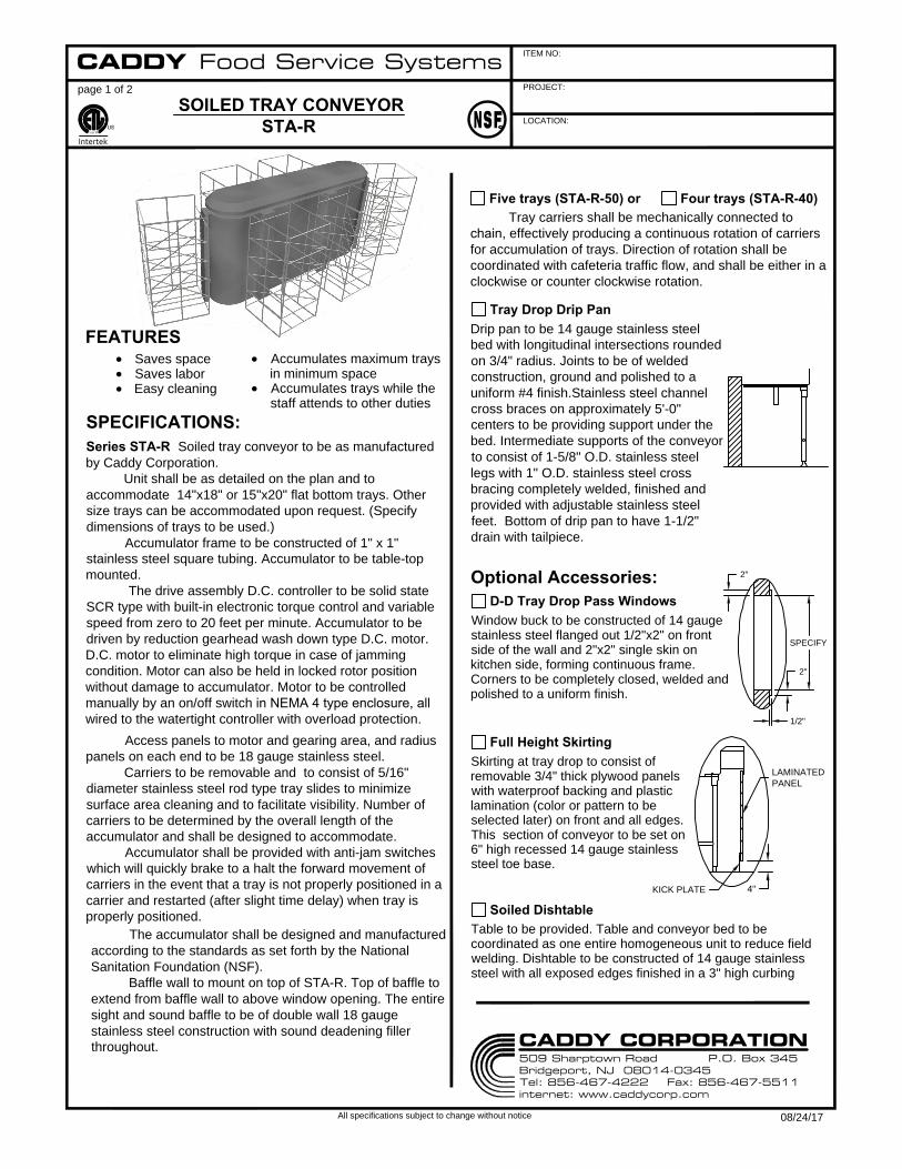
FEATURES
Saves space
Saves labor
Easy cleaning
The accumulator shall be designed and manufactured
according to the standards as set forth by the National
Sanitation Foundation (NSF).
Baffle wall to mount on top of STA-R. Top of baffle to
extend from baffle wall to above window opening. The entire
sight and sound baffle to be of double wall 18 gauge
stainless steel construction with sound deadening filler
throughout.
SPECIFICATIONS:
Accumulates maximum trays
in minimum space
Accumulates trays while the
staff attends to other duties
Series STA-R Soiled tray conveyor to be as manufactured
by Caddy Corporation.
Unit shall be as detailed on the plan and to
accommodate 14"x18" or 15"x20" flat bottom trays. Other
size trays can be accommodated upon request. (Specify
dimensions of trays to be used.)
Accumulator frame to be constructed of 1" x 1"
stainless steel square tubing. Accumulator to be table-top
mounted.
The drive assembly D.C. controller to be solid state SCR type with built-in electronic torque control and variable speed from zero to 20 feet per minute. Accumulator to be driven by reduction gearhead wash down type D.C. motor. D.C. motor to eliminate high torque in case of jamming condition. Motor can also be held in locked rotor position without damage to accumulator. Motor to be controlled manually by an on/off switch in NEMA 4 type enclosure, all
wired to the watertight controller with overload protection. Access panels to motor and gearing area, and radius
panels on each end to be 18 gauge stainless steel.
Carriers to be removable and to consist of 5/16"
diameter stainless steel rod type tray slides to minimize
surface area cleaning and to facilitate visibility. Number of
carriers to be determined by the overall length of the
accumulator and shall be designed to accommodate.
Accumulator shall be provided with anti-jam switches
which will quickly brake to a halt the forward movement of
carriers in the event that a tray is not properly positioned in a
carrier and restarted (after slight time delay) when tray is
properly positioned.
Five trays (STA-R-50) or Four trays (STA-R-40)
Tray carriers shall be mechanically connected to chain, effectively producing a continuous rotation of carriers
for accumulation of trays. Direction of rotation shall be coordinated with cafeteria traffic flow, and shall be either in a clockwise or counter clockwise rotation.
Window buck to be constructed of 14 gauge
stainless steel flanged out 1/2"x2" on front
side of the wall and 2"x2" single skin on
kitchen side, forming continuous frame.
Corners to be completely closed, welded and
polished to a uniform finish.
Optional Accessories:
D-D Tray Drop Pass Windows
Drip pan to be 14 gauge stainless steel
bed with longitudinal intersections rounded
on 3/4" radius. Joints to be of welded
construction, ground and polished to a
uniform #4 finish.Stainless steel channel
cross braces on approximately 5'-0"
centers to be providing support under the
bed. Intermediate supports of the conveyor
to consist of 1-5/8" O.D. stainless steel
legs with 1" O.D. stainless steel cross
bracing completely welded, finished and
provided with adjustable stainless steel
feet. Bottom of drip pan to have 1-1/2"
drain with tailpiece.
Tray Drop Drip Pan
Skirting at tray drop to consist of
removable 3/4" thick plywood panels
with waterproof backing and plastic
lamination (color or pattern to be
selected later) on front and all edges.
This section of conveyor to be set on
6" high recessed 14 gauge stainless
steel toe base.
Full Height Skirting
Table to be provided. Table and conveyor bed to be
coordinated as one entire homogeneous unit to reduce field
welding. Dishtable to be constructed of 14 gauge stainless
steel with all exposed edges finished in a 3" high curbing
Soiled Dishtable
CADDY Food Service Systems
509 Sharptown Road P.O. Box 345Bridgeport, NJ 08014-0345Tel: 856-467-4222 Fax: 856-467-5511internet: www.caddycorp.com
CADDY CORPORATION
08/24/17
3"
1 1/2"
45° TURN UP
3'-0 1/2"
3'-6"
2'-4"
5'-8"
3'-4"
SILVER SAVER
ROD
FLUSHING
DEVISE
DISPOSER
SINK
PROJECT:
ITEM NO:
LOCATION:
All specifications subject to change without notice
CM
Intertek
Optional Accessories Continued:
page 2 of 2
with 1-1/2" diameter 180 degree rolled rim with corners
bullnosed. All corners to be rounded horizontally and
vertically forming a cove at intersection. Joints to be
continuously welded, ground and polished to a #4 finish to
appear as one continuous surface free of buckles and weld
marks. Next to conveyor bed,
the table surface is to be sloped
up at a 45 degree angle. Top to
be cross braced with 14 gauge
stainless steel channel stiffeners
welded to the underside. Cross
stiffeners to be at leg assembly
stations on approximately 5'-0"
centers. Legs to be constructed
as specified for the conveyor
with cross bracing as required to
provide a rigid assembly.
SOILED TRAY CONVEYOR
STA-R
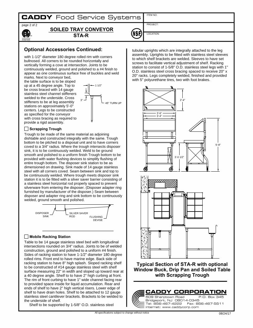
tubular uprights which are integrally attached to the leg
assembly. Uprights to be fitted with stainless steel sleeves
to which shelf brackets are welded. Sleeves to have set
screws to facilitate vertical adjustment of shelf. Racking
station to consist of 1-5/8" O.D. stainless steel legs with 1"
O.D. stainless steel cross bracing spaced to receive 20" x
20" racks. Legs completely welded, finished and provided
with 5" polyurethane tires, two with foot brakes.
Typical Section of STA-R with optional
Window Buck, Drip Pan and Soiled Table
with Scrapping Trough
Scrapping Trough
Trough to be made of the same material as adjoining
dishtable and constructed integrally with the same. Trough
bottom to be pitched to a disposal unit and to have corners
coved to a 3/4" radius. Where the trough intersects disposer
sink, it is to be continuously welded. Weld to be ground
smooth and polished to a uniform finish Trough bottom to be
provided with water flushing devices to simplify flushing of
entire trough bottom. The disposer sink station to be as
dimensioned on drawing. Sink made of 14 gauge stainless
steel with all corners coved. Seam between sink and top to
be continuously welded. Where trough meets disposer sink
station it is to be fitted with a silver saver barrier consisting of
a stainless steel horizontal rod properly spaced to prevent
silverware from entering the disposer. (Disposer adapter ring
furnished by manufacturer of the disposer.) Seam between
disposer and adapter ring and sink bottom to be continuously
welded, ground smooth and polished.
Mobile Racking Station
Table to be 14 gauge stainless steel bed with longitudinal
intersections rounded on 3/4" radius. Joints to be of welded
construction, ground and polished to a uniform #4 finish.
Sides of racking station to have 1-1/2" diameter 180 degree
rolled rims. Front end to have marine edge. Back side of
racking station to have 8" high splash. Sloped racking shelf
to be constructed of #14 gauge stainless steel with shelf
surface measuring 22" in width and sloped up toward rear at
a 40 degree angle. Shelf to to have 2" high curbing at front.
The rim of front curbing to have 1" wide channel facing rear
to provided space inside for liquid accumulation. Rear and
ends of shelf to have 2" high vertical risers. Lower edge of
shelf to have drain holes. Shelf to be attached to 12 gauge
stainless steel cantilever brackets. Brackets to be welded to
the underside of shelf.
Shelf to be supported by 1-5/8" O.D. stainless steel
CADDY Food Service Systems
509 Sharptown Road P.O. Box 345Bridgeport, NJ 08014-0345Tel: 856-467-4222 Fax: 856-467-5511internet: www.caddycorp.com
CADDY CORPORATION
08/24/17
PROJECT:
ITEM NO:
LOCATION:
page 1 of 1
All specifications subject to change without notice
BUSING CONVEYOR
BU-10-10 SERIES
CM
Intertek
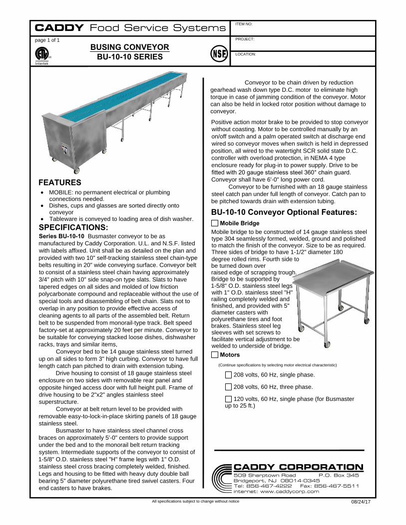
FEATURES
MOBILE: no permanent electrical or plumbing
connections needed.
Dishes, cups and glasses are sorted directly onto
conveyor
Tableware is conveyed to loading area of dish washer.
SPECIFICATIONS:
Series BU-10-10 Busmaster conveyor to be as
manufactured by Caddy Corporation. U.L. and N.S.F. listed
with labels affixed. Unit shall be as detailed on the plan and
provided with two 10" self-tracking stainless steel chain-type
belts resulting in 20" wide conveying surface. Conveyor belt
to consist of a stainless steel chain having approximately
3/4" pitch with 10" side snap-on type slats. Slats to have
tapered edges on all sides and molded of low friction
polycarbonate compound and replaceable without the use of
special tools and disassembling of belt chain. Slats not to
overlap in any position to provide effective access of
cleaning agents to all parts of the assembled belt. Return
belt to be suspended from monorail-type track. Belt speed
factory-set at approximately 20 feet per minute. Conveyor to
be suitable for conveying stacked loose dishes, dishwasher
racks, trays and similar items,
Conveyor bed to be 14 gauge stainless steel turned
up on all sides to form 3" high curbing. Conveyor to have full
length catch pan pitched to drain with extension tubing.
Drive housing to consist of 18 gauge stainless steel
enclosure on two sides with removable rear panel and
opposite hinged access door with full height pull. Frame of
drive housing to be 2"x2" angles stainless steel
superstructure.
Conveyor at belt return level to be provided with
removable easy-to-lock-in-place skirting panels of 18 gauge
stainless steel.
Busmaster to have stainless steel channel cross
braces on approximately 5'-0" centers to provide support
under the bed and to the monorail belt return tracking
system. Intermediate supports of the conveyor to consist of
1-5/8" O.D. stainless steel "H" frame legs with 1" O.D.
stainless steel cross bracing completely welded, finished.
Legs and housing to be fitted with heavy duty double ball
bearing 5" diameter polyurethane tired swivel casters. Four
end casters to have brakes.
Positive action motor brake to be provided to stop conveyor
without coasting. Motor to be controlled manually by an
on/off switch and a palm operated switch at discharge end
wired so conveyor moves when switch is held in depressed
position, all wired to the watertight SCR solid state D.C.
controller with overload protection, in NEMA 4 type
enclosure ready for plug-in to power supply. Drive to be
fitted with 20 gauge stainless steel 360° chain guard.
Conveyor shall have 6'-0" long power cord.
Conveyor to be furnished with an 18 gauge stainless
steel catch pan under full length of conveyor. Catch pan to
be pitched towards drain with extension tubing.
BU-10-10 Conveyor Optional Features:
Mobile bridge to be constructed of 14 gauge stainless steel
type 304 seamlessly formed, welded, ground and polished
to match the finish of the conveyor. Size to be as required.
Three sides of bridge to have 1-1/2" diameter 180
Mobile Bridge
degree rolled rims. Fourth side to
be turned down over
raised edge of scrapping trough.
Bridge to be supported by
1-5/8" O.D. stainless steel legs
with 1" O.D. stainless steel "H"
railing completely welded and
finished, and provided with 5"
diameter casters with
polyurethane tires and foot
brakes. Stainless steel leg
sleeves with set screws to
facilitate vertical adjustment to be
welded to underside of bridge.
208 volts, 60 Hz, single phase.
Motors
(Continue specifications by selecting motor electrical characteristic)
208 volts, 60 Hz, three phase.
120 volts, 60 Hz, single phase (for Busmaster
up to 25 ft.)
CADDY Food Service Systems
509 Sharptown Road P.O. Box 345Bridgeport, NJ 08014-0345Tel: 856-467-4222 Fax: 856-467-5511internet: www.caddycorp.com
CADDY CORPORATION
08/24/17
Conveyor to be chain driven by reduction
gearhead wash down type D.C. motor to eliminate high
torque in case of jamming condition of the conveyor. Motor
can also be held in locked rotor position without damage to
conveyor.
PROJECT:
ITEM NO:
LOCATION:
page 1 of 3
All specifications subject to change without notice
SORTING CONVEYOR
SV-10-10 SERIES
CM
Intertek
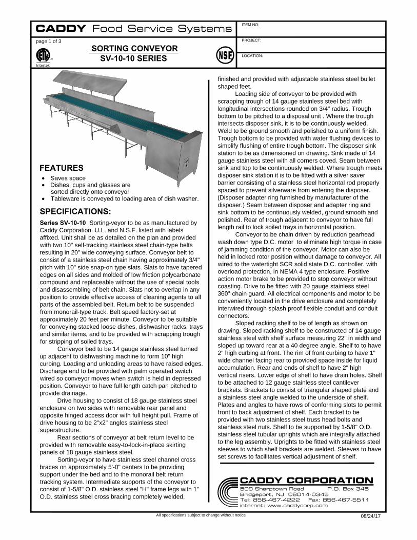
FEATURES
Saves space
Dishes, cups and glasses are
sorted directly onto conveyor
Tableware is conveyed to loading area of dish washer.
SPECIFICATIONS:
Series SV-10-10 Sorting-veyor to be as manufactured by
Caddy Corporation. U.L. and N.S.F. listed with labels
affixed. Unit shall be as detailed on the plan and provided
with two 10" self-tracking stainless steel chain-type belts
resulting in 20" wide conveying surface. Conveyor belt to
consist of a stainless steel chain having approximately 3/4"
pitch with 10" side snap-on type slats. Slats to have tapered
edges on all sides and molded of low friction polycarbonate
compound and replaceable without the use of special tools
and disassembling of belt chain. Slats not to overlap in any
position to provide effective access of cleaning agents to all
parts of the assembled belt. Return belt to be suspended
from monorail-type track. Belt speed factory-set at
approximately 20 feet per minute. Conveyor to be suitable
for conveying stacked loose dishes, dishwasher racks, trays
and similar items, and to be provided with scrapping trough
for stripping of soiled trays.
Conveyor bed to be 14 gauge stainless steel turned
up adjacent to dishwashing machine to form 10" high
curbing. Loading and unloading areas to have raised edges.
Discharge end to be provided with palm operated switch
wired so conveyor moves when switch is held in depressed
position. Conveyor to have full length catch pan pitched to
provide drainage.
Drive housing to consist of 18 gauge stainless steel
enclosure on two sides with removable rear panel and
opposite hinged access door with full height pull. Frame of
drive housing to be 2"x2" angles stainless steel
superstructure.
Rear sections of conveyor at belt return level to be
provided with removable easy-to-lock-in-place skirting
panels of 18 gauge stainless steel.
Sorting-veyor to have stainless steel channel cross
braces on approximately 5'-0" centers to be providing
support under the bed and to the monorail belt return
tracking system. Intermediate supports of the conveyor to
consist of 1-5/8" O.D. stainless steel "H" frame legs with 1"
O.D. stainless steel cross bracing completely welded,
finished and provided with adjustable stainless steel bullet
shaped feet.
Loading side of conveyor to be provided with
scrapping trough of 14 gauge stainless steel bed with
longitudinal intersections rounded on 3/4" radius. Trough
bottom to be pitched to a disposal unit . Where the trough
intersects disposer sink, it is to be continuously welded.
Weld to be ground smooth and polished to a uniform finish.
Trough bottom to be provided with water flushing devices to
simplify flushing of entire trough bottom. The disposer sink
station to be as dimensioned on drawing. Sink made of 14
gauge stainless steel with all corners coved. Seam between
sink and top to be continuously welded. Where trough meets
disposer sink station it is to be fitted with a silver saver
barrier consisting of a stainless steel horizontal rod properly
spaced to prevent silverware from entering the disposer.
(Disposer adapter ring furnished by manufacturer of the
disposer.) Seam between disposer and adapter ring and
sink bottom to be continuously welded, ground smooth and
polished. Rear of trough adjacent to conveyor to have full
length rail to lock soiled trays in horizontal position.
Conveyor to be chain driven by reduction gearhead
wash down type D.C. motor to eliminate high torque in case
of jamming condition of the conveyor. Motor can also be
held in locked rotor position without damage to conveyor. All
wired to the watertight SCR solid state D.C. controller. with
overload protection, in NEMA 4 type enclosure. Positive
action motor brake to be provided to stop conveyor without
coasting. Drive to be fitted with 20 gauge stainless steel
360° chain guard. All electrical components and motor to be
conveniently located in the drive enclosure and completely
interwired through splash proof flexible conduit and conduit
connectors.
Sloped racking shelf to be of length as shown on
drawing. Sloped racking shelf to be constructed of 14 gauge
stainless steel with shelf surface measuring 22" in width and
sloped up toward rear at a 40 degree angle. Shelf to to have
2" high curbing at front. The rim of front curbing to have 1"
wide channel facing rear to provided space inside for liquid
accumulation. Rear and ends of shelf to have 2" high
vertical risers. Lower edge of shelf to have drain holes. Shelf
to be attached to 12 gauge stainless steel cantilever
brackets. Brackets to consist of triangular shaped plate and
a stainless steel angle welded to the underside of shelf.
Plates and angles to have rows of conforming slots to permit
front to back adjustment of shelf. Each bracket to be
provided with two stainless steel truss head bolts and
stainless steel nuts. Shelf to be supported by 1-5/8" O.D.
stainless steel tubular uprights which are integrally attached
to the leg assembly. Uprights to be fitted with stainless steel
sleeves to which shelf brackets are welded. Sleeves to have
set screws to facilitates vertical adjustment of shelf.
CADDY Food Service Systems
509 Sharptown Road P.O. Box 345Bridgeport, NJ 08014-0345Tel: 856-467-4222 Fax: 856-467-5511internet: www.caddycorp.com
CADDY CORPORATION
08/24/17
1'-4"
PROJECT:
ITEM NO:
LOCATION:
page 2 of 3
All specifications subject to change without notice
SORTING CONVEYOR
SV-10-10 SERIES
CM
Intertek
BWF belt washer to consist of welded 16 gauge
stainless steel. Belt washer to have top and bottom fan
shaped sprays arranged so lukewarm water thoroughly
washes all belt surfaces after which belt is wiped
continuously. Belt washer to have hinged drop-down, splash
proof stainless steel access door. Washer to be fitted with
interconnected water pressure reducing valve, water
pressure gauge, shutoff valve and thermostatically
controlled mixing valve with check valves. Bottom of belt
washer to have 1-1/2" drain with tailpiece and two
removable stainless steel perforated scrap baskets. Belt
washer piping to be complete with approved type vacuum
breaker and check valve. All piping exposed to view to be
chrome plated. Operation of belt washer to be controlled by
solenoid valve integrally wired to time delay relay which is
activated by palm switch of conveyor. Belt washer will
operate for a period of 60 seconds after palm switch is
released. A separate On/Off switch to be provided to permit
operation of conveyor without belt washer.
Conveyor to be furnished with an 18 gauge stainless
steel catch pan under full length of conveyor. Catch pan to
be pitched towards belt washer.
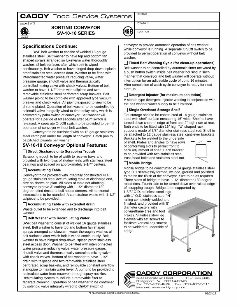
SV-10-10 Conveyor Optional Features:
Scrapping trough to be of width to receive trays and
provided with two rows of skatewheels with stainless steel
bearings and spaced on approximately 2-1/4" centers.
Direct Discharge onto Scrapping Trough
Conveyor to be provided with integrally constructed #14
gauge stainless steel accumulating table at discharge end,
size as shown on plan. All sides of table not abutting
conveyor to have 3" curbing with 1-1/2" diameter 180
degree rolled rims and bull nosed corners. All horizontal
intersections to be rounded. A cup strainer waste with 1-1/2"
tailpiece to be provided.
Accumulating Table
Waste outlet to be extended and to discharge into belt
washer.
Accumulating Table with extended drain
BWR belt washer to consist of welded 16 gauge stainless
steel. Belt washer to have top and bottom fan shaped
sprays arranged so lukewarm water thoroughly washes all
belt surfaces after which belt is wiped continuously. Belt
washer to have hinged drop-down, splash proof stainless
steel access door. Washer to be fitted with interconnected
water pressure reducing valve, water pressure gauge,
shutoff valve and thermostatically controlled mixing valve
with check valves. Bottom of belt washer to have 1-1/2"
drain with tailpiece and two removable stainless steel
perforated scrap baskets, and removable constant overflow
standpipe to maintain water level. A pump to be provided to
recirculate water from reservoir through spray nozzles.
Recirculating system to include a removable filter to
facilitate cleaning. Operation of belt washer to be controlled
by solenoid valve integrally wired to On/Off switch of
Belt Washer with Recirculating Water
conveyor to provide automatic operation of belt washer
while conveyor is running. A separate On/Off switch to be
provided to permit operation of conveyor without belt
washer.
Belt washer to be controlled by automatic timer activated by
a push button switch inside belt washer housing in such
manner that conveyor and belt washer will operate without
interruption for an adjustable cycle of up to 16 minutes.
After completion of wash cycle conveyor is ready for next
start-up.
Timed Belt Washing Cycle (for clean-up operations)
A siphon type detergent injector working in conjunction with
the belt washer water supply to be furnished.
Detergent Injector (for maximum sanitation)
Flat storage shelf to be constructed of 14 gauge stainless
steel with shelf surface measuring 16" wide. Shelf to have
turned down channel edge at front and 2" high riser at rear.
Both ends to be fitted with 16" high "U" shaped rack
supports made of 3/8" diameter stainless steel rod. Shelf to
be attached to 12 gauge stainless steel cantilever brackets
Single Overhead Storage Shelf
Brackets to be welded to the underside
of shelf. Plates and angles to have rows
of conforming slots to permit front to
back adjustment of shelf. Each bracket
to be provided with two stainless steel
truss head bolts and stainless steel nut.
Mobile bridge to be constructed of 14 gauge stainless steel
type 301 seamlessly formed, welded, ground and polished
to match the finish of the conveyor. Size to be as required.
Three sides of bridge to have 1-1/2" diameter 180 degree
rolled rims. Fourth side to be turned down over raised edge
of scrapping trough. Bridge to be supported by
Mobile Bridge
1-5/8" O.D. stainless steel legs
with 1" O.D. stainless steel "H"
railing completely welded and
finished, and provided with 5"
diameter casters with
polyurethane tires and foot
brakes. Stainless steel leg
sleeves with set screws to
facilitate vertical adjustment
to be welded to underside of
bridge.
Specifications Continue:
CADDY Food Service Systems
509 Sharptown Road P.O. Box 345Bridgeport, NJ 08014-0345Tel: 856-467-4222 Fax: 856-467-5511internet: www.caddycorp.com
CADDY CORPORATION
08/24/17

A
CB
D
E
F
2'-6"
MINIMUM REQUIRED
FOR ACCESS TO
DISH WASHER INTERIOR
NOTE: ALL ROUGH-INS TO BE 4"AFF
DESCRIPTION
ROUGH-IN SCHEDULE
1 1/2" I.P.S. WASTE
SYM
A
1/2" I.P.S. HOT WATER
B
1/2" I.P.S. COLD WATER
C
1/2 H.P. (SEE BELOW
D
1/2" I.P.S. WATER INLET
E
1 1/2" I.P.S. WASTE
F
(IF ACCUMULAATING TABLE IS PROVIDED)
FOR AVAILABLE ELEC. CHARACTERISTIC
3'-4 1/4"
3'-0 1/2"
PROJECT:
ITEM NO:
LOCATION:
page 3 of 3
All specifications subject to change without notice
SORTING CONVEYOR
SV-10-10 SERIES
CM
Intertek
TYPICAL ROUGHING, PLUMBING AND ELECTRICAL DATA
Motors available: 208/230/460 volts, 60
Hz, three phase. 120 volts, 60 Hz, single
phase (for Sorting-Veyor up to 25 ft. long)
Typical Section View
CADDY Food Service Systems
509 Sharptown Road P.O. Box 345Bridgeport, NJ 08014-0345Tel: 856-467-4222 Fax: 856-467-5511internet: www.caddycorp.com
CADDY CORPORATION
08/24/17
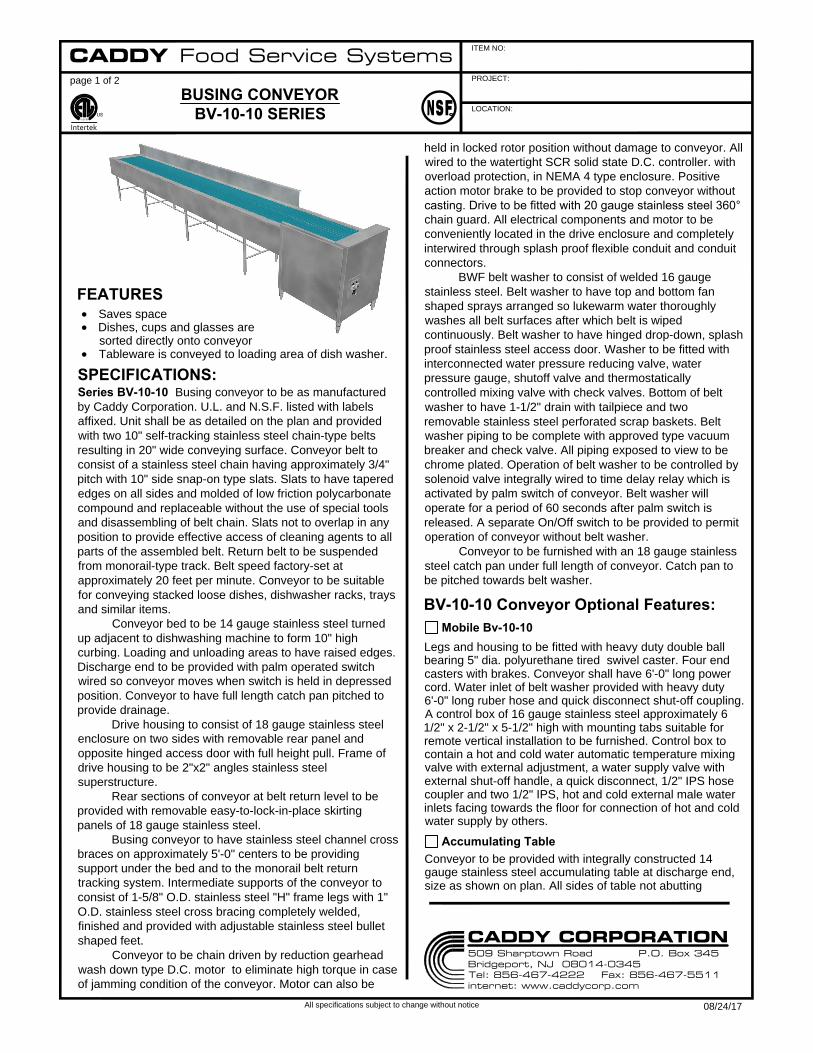
PROJECT:
ITEM NO:
LOCATION:
page 1 of 2
All specifications subject to change without notice
BUSING CONVEYOR
BV-10-10 SERIES
CM
Intertek
FEATURES
Saves space
Dishes, cups and glasses are
sorted directly onto conveyor
Tableware is conveyed to loading area of dish washer.
SPECIFICATIONS:
Series BV-10-10 Busing conveyor to be as manufactured
by Caddy Corporation. U.L. and N.S.F. listed with labels
affixed. Unit shall be as detailed on the plan and provided
with two 10" self-tracking stainless steel chain-type belts
resulting in 20" wide conveying surface. Conveyor belt to
consist of a stainless steel chain having approximately 3/4"
pitch with 10" side snap-on type slats. Slats to have tapered
edges on all sides and molded of low friction polycarbonate
compound and replaceable without the use of special tools
and disassembling of belt chain. Slats not to overlap in any
position to provide effective access of cleaning agents to all
parts of the assembled belt. Return belt to be suspended
from monorail-type track. Belt speed factory-set at
approximately 20 feet per minute. Conveyor to be suitable
for conveying stacked loose dishes, dishwasher racks, trays
and similar items.
Conveyor bed to be 14 gauge stainless steel turned
up adjacent to dishwashing machine to form 10" high
curbing. Loading and unloading areas to have raised edges.
Discharge end to be provided with palm operated switch
wired so conveyor moves when switch is held in depressed
position. Conveyor to have full length catch pan pitched to
provide drainage.
Drive housing to consist of 18 gauge stainless steel
enclosure on two sides with removable rear panel and
opposite hinged access door with full height pull. Frame of
drive housing to be 2"x2" angles stainless steel
superstructure.
Rear sections of conveyor at belt return level to be
provided with removable easy-to-lock-in-place skirting
panels of 18 gauge stainless steel.
Busing conveyor to have stainless steel channel cross
braces on approximately 5'-0" centers to be providing
support under the bed and to the monorail belt return
tracking system. Intermediate supports of the conveyor to
consist of 1-5/8" O.D. stainless steel "H" frame legs with 1"
O.D. stainless steel cross bracing completely welded,
finished and provided with adjustable stainless steel bullet
shaped feet.
Conveyor to be chain driven by reduction gearhead
wash down type D.C. motor to eliminate high torque in case
of jamming condition of the conveyor. Motor can also be
held in locked rotor position without damage to conveyor. All
wired to the watertight SCR solid state D.C. controller. with
overload protection, in NEMA 4 type enclosure. Positive
action motor brake to be provided to stop conveyor without
casting. Drive to be fitted with 20 gauge stainless steel 360°
chain guard. All electrical components and motor to be
conveniently located in the drive enclosure and completely
interwired through splash proof flexible conduit and conduit
connectors.
BWF belt washer to consist of welded 16 gauge
stainless steel. Belt washer to have top and bottom fan
shaped sprays arranged so lukewarm water thoroughly
washes all belt surfaces after which belt is wiped
continuously. Belt washer to have hinged drop-down, splash
proof stainless steel access door. Washer to be fitted with
interconnected water pressure reducing valve, water
pressure gauge, shutoff valve and thermostatically
controlled mixing valve with check valves. Bottom of belt
washer to have 1-1/2" drain with tailpiece and two
removable stainless steel perforated scrap baskets. Belt
washer piping to be complete with approved type vacuum
breaker and check valve. All piping exposed to view to be
chrome plated. Operation of belt washer to be controlled by
solenoid valve integrally wired to time delay relay which is
activated by palm switch of conveyor. Belt washer will
operate for a period of 60 seconds after palm switch is
released. A separate On/Off switch to be provided to permit
operation of conveyor without belt washer.
Conveyor to be furnished with an 18 gauge stainless
steel catch pan under full length of conveyor. Catch pan to
be pitched towards belt washer.
BV-10-10 Conveyor Optional Features:
Mobile Bv-10-10
Legs and housing to be fitted with heavy duty double ball
bearing 5" dia. polyurethane tired swivel caster. Four end
casters with brakes. Conveyor shall have 6'-0" long power
cord. Water inlet of belt washer provided with heavy duty
6'-0" long ruber hose and quick disconnect shut-off coupling.
A control box of 16 gauge stainless steel approximately 6
1/2" x 2-1/2" x 5-1/2" high with mounting tabs suitable for
remote vertical installation to be furnished. Control box to
contain a hot and cold water automatic temperature mixing
valve with external adjustment, a water supply valve with
external shut-off handle, a quick disconnect, 1/2" IPS hose
coupler and two 1/2" IPS, hot and cold external male water
inlets facing towards the floor for connection of hot and cold
water supply by others.
Conveyor to be provided with integrally constructed 14
gauge stainless steel accumulating table at discharge end,
size as shown on plan. All sides of table not abutting
Accumulating Table
CADDY Food Service Systems
509 Sharptown Road P.O. Box 345Bridgeport, NJ 08014-0345Tel: 856-467-4222 Fax: 856-467-5511internet: www.caddycorp.com
CADDY CORPORATION
08/24/17

NOTE: ALL ROUGH-INS TO BE 4"AFF
DESCRIPTION
ROUGH-IN SCHEDULE
1 1/2" I.P.S. WASTE (FOR MOBILE UNIT PROVIDE 10" DIA. FUNNEL
SYM
A
1/2" I.P.S. HOT WATER (FOR STATIONARY UNIT ONLY)B
1/2" I.P.S. COLD WATER (FOR STATIONARY UNIT ONLY)C
1/2 H.P. ( FOR STATIONARY UNIT ONLY SEE BELOW FOR AVAILABLE
1 1/2" I.P.S. WASTE (IF ACCUMULATING TABLE IS PROVIDED, OPTIONAL)E
1/2 H.P. ( FOR MOBILE UNIT ONLY SEE BELOW FOR AVAILABLE ELECTRIC
CHARACTERISTIC) PLUG-IN RECEPTACLE SUPPLIED BY ELECTRICAL
ELECTRIC CHARACTERISTIC)
1/2" I.P.S. HOT WATER (FOR MOBILE UNIT ONLY)G
1/2" I.P.S. COLD WATER (FOR MOBILE UNIT ONLY)H
TOP-FLOOR DRAIN IN THIS LOCATION)
D
F
CONTRACTOR
2'-5"
3'-0 1/2"
MINIMUM REQUIRED
FOR ACCESS TO
DISH WASHER INTERIOR
E
CB
D
A
FGH
PROJECT:
ITEM NO:
LOCATION:
page 2 of 2
All specifications subject to change without notice
BUSING CONVEYOR
BV-10-10 SERIES
CM
Intertek
BV-10-10 Conveyor Optional Features:
conveyor to have 3" curbing with 1-1/2" diameter 180
degree rolled rims and bull nosed corners. All horizontal
intersections to be rounded. A cup strainer waste with 1-1/2"
tailpiece to be provided.
Waste outlet to be extended and to be discharge into belt
washer.
Accumulating Table with extended drain
BWR belt washer to consist of welded 16 gauge stainless
steel. Belt washer to have top and bottom fan shaped
sprays arranged so lukewarm water thoroughly washes all
belt surfaces after which belt is wiped continuously. Belt
washer to have hinged drop-down, splash proof stainless
steel access door. Washer to be fitted with interconnected
water pressure reducing valve, water pressure gauge,
shutoff valve and thermostatically controlled mixing valve
with check valves. Bottom of belt washer to have 1-1/2"
drain with tailpiece and two removable stainless steel
perforated scrap baskets, and removable constant overflow
standpipe to maintain water level. A pump to be provided to
recirculate water from reservoir through spray nozzles.
Recirculating system to include a removable filter to
facilitate cleaning. Operation of belt washer to be controlled
by solenoid valve integrally wired to On/Off switch of
conveyor to provide automatic operation of belt washer
while conveyor is running. A separate On/Off switch to be
provided to permit operation of conveyor without belt
washer.
Belt Washer with Recirculating Water
Belt washer to be controlled by automatic timer activated by
a push button switch inside belt washer housing in such
manner that conveyor and belt washer will operate without
interruption for an adjustable cycle of up to 16 minutes.
After completion of wash cycle conveyor is ready for next
start-up.
Timed Belt Washing Cycle (for clean-up operations)
A pump type detergent injector working in conjunction with
the belt washer water supply to be furnished.
Detergent Injector (for maximum sanitation)
Mobile bridge to be constructed of 14 gauge stainless steel
type 301 seamlessly formed, welded, ground and polished
to match the finish of the conveyor. Size to be as required.
Three sides of bridge to have 1-1/2" diameter 180 degree
rolled rims. Fourth side to be turned down over raised edge
of scrapping trough. Bridge to be supported by
Mobile Bridge
1-5/8" O.D. stainless steel legs
with 1" O.D. stainless steel "H"
railing completely welded and
finished, and provided with 5"
diameter casters with
polyurethane tires and foot
brakes. Stainless steel leg
sleeves with set screws to
facilitate vertical adjustment
to be welded to underside of
bridge.
TYPICAL ROUGHING,
PLUMBING AND
ELECTRICAL DATA
Motors available: 208/230/460 volts, 60
Hz, three phase. 120 volts, 60 Hz, single
phase (for Busing-Veyor up to 25 ft. long)
Typical Section View
CADDY Food Service Systems
509 Sharptown Road P.O. Box 345Bridgeport, NJ 08014-0345Tel: 856-467-4222 Fax: 856-467-5511internet: www.caddycorp.com
CADDY CORPORATION
08/24/17