soil structure interaction starts with engineers · soil structure interaction starts with...
TRANSCRIPT
Paper Number XXX
Soil Structure Interaction Starts With Engineers
2013 NZSEE Conference
Stuart Oliver & John Hare
Holmes Consulting Group, Christchurch, New Zealand.
Nick Harwood
Coffey Geotechnics, Christchurch, New Zealand.
ABSTRACT: Poor performance of some buildings in the 2011 Christchurch earthquakes
has emphasised the need for a greater focus on the seismic resilience of building
foundations and improved interaction between geotechnical and structural engineers.
While comprehensive prescriptive requirements are contained within Building Code
Compliance Documents for above ground building elements, little guidance is provided
for the design and analysis of building foundations or how to assess and accommodate
soil structure interaction. This compliance gap, coupled with inconsistencies in
geotechnical and structural engineering design practice can increase the risk of
unsatisfactory foundation performance.
This paper provides an overview of the key geotechnical and structural engineering
issues, discusses how some aspects of current design practice might be improved and
provides recommendations for further improvements and research.
1 INTRODUCTION
Poor performance of some buildings in the 2011 Christchurch earthquakes has emphasised the need
for a greater focus on the seismic resilience of building foundations and improved interaction between
geotechnical and structural Engineers. Foundation systems form an important part of a structures
primary vertical and lateral load resisting systems, and poor performance of a foundation system can
lead to significant building settlements and consequential damage, and in extreme cases, building
collapse.
A number of buildings in Christchurch, which may have otherwise been repairable, have been
demolished following the February 2011 Christchurch earthquake as a result of poor foundation
performance. As the trend toward low damage design continues it is important that we apply
comparable, or better, levels of building performance requirements to foundations systems.
2 NZ CODE REQUIREMENTS FOR FOUNDATION SYSTEMS
Unlike most other aspects of building design, which are governed by highly prescriptive standards, the
design of foundation systems is inadequately covered in New Zealand Building Code compliance
documents.
Aspects of foundation design rely on engineering judgement rather than code prescribed limits. It is
worth noting that this may not be an issue, provided that those undertaking the design are competent
and that there is mutual understanding between the geotechnical and structural engineers of the design
objectives and outcomes. It can, however, lead to varying levels of foundation performance, some of
which may be lower than that which is desired.
2.1 Clause B1 of the New Zealand Building Code
Building code requirements for foundation systems are detailed in Clause B1 of the New Zealand
Building Code (DBH 2011). Verification Method B1/VM4 prescribes the minimum strength
requirements for the ultimate limit state design of shallow foundations and conventional piles, and
provides suggested deformation limits for the serviceability limit state for buildings on good ground.
2
Buildings on poor ground, such as those founded on soils that may be subject to liquefaction during
earthquake loading, or sensitive clays that may be susceptible to a rapid loss of shear strength, are
outside the scope of the compliance document. The title page of the section in the Compliance
Document entitled Acceptable Solution B1/AS4 Foundations (revised by Amendment 4 in 2000)
states: “No specific acceptable solution for foundations has been adopted for complying with the
Performances of NZBC B1”. This is an omission that has an immediate need to be addressed.
2.2 New Zealand Earthquake Loadings Standard
The New Zealand earthquake loadings standard, NZS 1170.5 (SNZ 2004) requires consideration of
foundation deformations when calculating building deflections (refer Cl 7.1.2). This is reaffirmed in
the commentary where it is stated that:
“Foundations, including piles, and the supporting soils with which they interact should be
treated as part of the overall building structure and analysed as such.
Flexibility of foundations affects the response characteristics of the building by affecting period,
drift and the like, and affects the relative participation between dissimilar systems in the
resistance of lateral loads, such as between walls and frames.”
No guidance or references are provided in commentary in terms of how to include foundation
flexibility in the analysis model. Up until quite recently, industry practice has frequently been to
ignore foundation flexibility. Where flexibility has been accommodated, there has been little
consistency in the industry as to the methods adopted to achieve this.
2.3 New Zealand Concrete Structures Standard
NZS 3101, the New Zealand Concrete Structures (SNZ 2006) contains specific detailing requirements
for reinforced concrete footings, piles and pile caps. This includes a requirement that the foundation
shall maintain its ability to support design gravity loads while sustaining the chosen earthquake energy
dissipating mechanisms in the structure above. The latter is to include an allowance for the
development of overstrength actions when applicable.
2.4 Design of Shallow Foundations
It is common practice across New Zealand for engineers to derive values of bearing capacity for
shallow foundations using rudimentary ground investigation tools in often complex ground conditions.
Calculations are based on questionable concepts and crude, dated correlations from overseas (i.e. not
calibrated for NZ soils and its climatic conditions) to arrive at bearing capacity values for design that
are reported with undue accuracy and certainty.
A review (Harwood 2012) of commonly employed methods for bearing capacity assessment including
those given in NZBC Clause B1 Structure, NZS 3604 (SNZ 1999) and Stockwell (1977) found that a
disproportionate amount of reliance is placed on methods that have questionable applicability. None
of the methods adequately address seismic design.
3 COMPLIANCE GAP
Aspects of foundation design that are not addressed in the current NZ Building Code compliance
documents include, but are not limited to:
Requirements for buildings founded on poor ground i.e. where liquefiable soil or sensitive
clays maybe present.
Maximum permissible foundation deflections at the ultimate and serviceability limit states.
This should include consideration of both vertical and horizontal deformations; and transient
and permanent deflections.
Design criteria for rocking foundation systems. These were included in the previous loadings
standard, NZS 4203 (SNZ 1992), however the provisions were not carried over into
NZS 1170.5 (SNZ 2004).
3
Lateral earth pressures on basement structures and foundations due to ground motions,
including consideration of liquefaction and lateral spreading. This may be particularly critical
for buildings on sloping sites, or those which have adjacent buildings with basements.
Design criteria for soil yielding at the ultimate limit state for both shallow and deep
foundations i.e. localised soil plasticity under pad footings or vertical plunging of piles sliding
with skin friction.
Assessment of the effects of soil structure interaction on building performance.
4 INCONSISTENCIES BETWEEN GEOTECHNICAL & STRUCTURAL ENGINEERS
Clear lines of communication between geotechnical and structural consultants is a key component of a
successful foundation design. Poor communication can lead to misunderstandings and poor design
outcomes i.e. overly conservative foundation designs, or worse, unsatisfactory foundation
performance. Often it is found that geotechnical and structural engineers have different performance
objectives in mind, or simply do not clearly understand what each discipline contributes or is able to
contribute to the design process, or what actually matters for design.
4.1 Terminology
A common source of misunderstanding between geotechnical and structural consultants is the
differing terminology used to describe design parameters. Table 1 illustrates some common examples.
Table 1 Terminology used to describe common design parameters
NZS 1170 Terminology Common alternative wording or
interpretations of the NZS1170 terms
ULS design action, Ru Fully factored loads, ultimate design
loads
Nominal capacity (5th
percentile), Rn Unfactored capacity, ultimate capacity,
ultimate strength, ultimate geotechnical
capacity
ULS design capacity, Rn Design capacity, allowable ultimate
capacity, geotechnical limit state design
strength, allowable capacity
Overstrength design action, Ro Overstrength load
Strength reduction factor, SFR, Factor of safety
SLS design action, Rs Unfactored loads, SLS design load
Another example of potentially misleading terms is present in B1/VM4 where Section 3.3.2 (entitled
‘Ultimate bearing strength’) covers the topic of bearing capacity. Although the units of both are
pressure (force/area), the strength and capacity of a soil mass are very different properties that should
not be confused. Furthermore, there is more than one type of strength that can be determined for a soil
sample and there are several different capacity definitions e.g. gross, net, total, effective, ultimate,
safe, allowable, and presumed.
In some cases the differing terminologies are easy to translate; in other situations it can be less clear.
The authors know of more than one occasion when a structural engineer has inadvertently used the
ultimate geotechnical capacity to size a foundation element.
There is a clear need to develop a common set of terms that can be used by both structural and
geotechnical consultants to design foundation systems. This could be included in future Building
Code compliance document revisions or as a Technical Memo. A course could be run to cover these
issues to provide important Continuing Professional Development.
4.2 Capacity Design
Another aspect of building design that is not well understood by all parties is application of
overstrength design actions associated with “capacity” design. Capacity design is a design process
whereby distinct elements of a structural system are chosen, and suitably designed and detailed for
4
energy dissipation during a major earthquake. All other structural elements are then protected against
actions that could cause failure. This is done by providing those elements with a greater strength than
that corresponding to the development of the energy dissipating mechanisms selected for the building
(Paulay & Priestley 1992).
When capacity design principles are used, the overstrength design actions on foundation elements, Ro,
can be calculated as:
uoo RR (1)
where o = overstrength factor and Ru = ULS design action. For a simple cantilever reinforced
concrete shear structure the overstrength factor, o, for used for the foundation design is calculated as:
u
nfy,o
oM
M (2)
where o,fy = material overstrength factor which accounts for the difference between the 5th percentile
material strengths and the “maximum-feasible” strengths which are higher due to strain hardening and
other related factors (refer NZS 3101); Mn = the nominal flexural capacity of the wall calculated using
5th percentile strengths; and Mu = ULS design bending moment for the element. For conventional
reinforced concrete walls with G300 reinforcing steel o,fy = 1.25. In typical design situations o
typically lies in a range of between 1.5 to 2.5.
It is worth noting that the material overstrength factors, o,fy, used by structural engineers have been
determined by means of a statistical analysis. This means that in practice, like other ULS design load
cases (i.e. wind), foundation systems may experience loads that are greater than that determined using
capacity design. Following submissions to, and reporting by, the Canterbury Earthquake Royal
Commission, SESOC is developing structural design guidance including advice and recommendations
on foundation design, including, for example, that designers should no longer use the higher strength
reduction factors permitted in B1/VM4 for load combinations involving earthquake overstrength
design actions.
4.3 Soil Properties for Structural Analysis
By virtue of the inherent variability of natural soil deposits, a particular soil property will have a
scatter of values from which the geotechnical engineer will determine recommended design values,
which are reported to and used by the structural engineer. Often the rationale for the selection of a
particular value is not reported. Derivation of recommended design values is influence by numerous
factors. For example, a conservative value may be given when a limited site investigation is
undertaken, published correlations are used to obtain design parameters or there will be minimal
construction control. Conversely, a more characteristic strength may be given when comprehensive
site investigation and laboratory testing is undertaken, site-specific correlations are used for design
parameters and where there will be careful construction control.
When the stiffness of foundation soils is included in a global analysis building model it is important
that the probable/expected design values are used. The short-term cyclic nature of seismic loading and
its effect on soil behaviour also requires consideration (including liquefaction when appropriate).
Stiffness parameters used to assess long-term building settlements may not be appropriate for the ULS
seismic analysis.
It is important that all parties involved are aware that even after a detailed geotechnical investigation
has been undertaken, there will still be considerable uncertainty with regard to how a soil will behave.
It is for this reason that it is recommended that when foundation soils are included in an analysis
model that an upper and lower bound approach be adopted. In lieu of an explicit evaluation of the
uncertainties in foundation characteristics it is recommended to take the upper bound stiffness as two
times the expected design value and the lower bound stiffness as one half of the expected design value
(ASCE 2007, NIST 2010). The resulting maxima from the two analyses should then be used for the
subsequent building design.
5
4.4 Seismic design of shallow foundations
Design issues that should be addressed when designing shallow foundations in a seismic environment
include (Harwood 2012):
The ultimate bearing capacity of the foundation when seismic (inertial) forces are acting;
Foundation stiffness and damping, and the movements (vertical, horizontal and rotational) of
the foundation;
The possible reduction in soil strength and bearing capacity due to the build-up of pore
pressures during seismic action;
The effects of liquefaction on foundation capacity;
The ground settlement and foundation settlement that may be developed if liquefaction occurs;
On sloping ground or ground in proximity of a ‘free face’, the compounding adverse effects of
lateral spread if liquefaction occurs;
Loss of ground under and/or around foundations due to sand/silt ejection; and
Sliding of the foundation.
This list provides a checklist for the designer. Unless it is ascertained for the particular structure that a
seismic issue is a secondary effect that can be safely ignored, the engineer should assume that the
influences are required to be specifically evaluated and appropriately accounted for in design.
Eurocode 8: Part 5 (CEN 2004) provides a useful set of design principles and advice on seismic design
of foundations, including:
The susceptibility of foundation soils to densification and to excessive settlements caused by
earthquake-induced cyclic stresses shall be taken into account when extended layers or thick
lenses of loose, unsaturated cohesionless materials exist at a shallow depth;
Attention is drawn to the fact that some sensitive clays might suffer a shear strength
degradation, and that cohesionless materials are susceptible to dynamic pore pressure build-up
under cyclic loading as well as to the upwards dissipation of the pore pressure from
underlying layers after an earthquake;
The evaluation of the bearing capacity of soil under seismic loading should take into account
possible strength and stiffness degradation mechanisms which might start even at relatively
low strain levels;
The rise of pore water pressure under cyclic loading should be taken into account, either by
considering its effect on undrained strength (in total stress analysis) or on pore pressure (in
effective stress analysis);
If the settlements caused by densification or cyclic degradation appear capable of affecting the
stability of the foundations, consideration should be given to ground improvement methods;
Depending on the structure’s importance, non-linear soil behaviour should be taken into
account in determining possible permanent deformation during earthquakes.
The Eurocodes generally provide a stringent framework for geotechnical seismic design taking into
account the structure, the foundation and the ground as a holistic “engineering system”. Although
these Codes were developed for the European Community there are many useful and highly relevant
design principles applicable to New Zealand.
4.5 Briefing and Interaction
One method to improve communication between structural and geotechnical engineers is for the
structural engineer to provide a Geotechnical Brief for the geotechnical engineer at the start of the
project. This document should clearly outline the nature of the project, including any unusual
performance requirements (i.e. low damage design), detail the scope of geotechnical information
required and what the design information is to be used for.
6
Regular design meetings between structural and geotechnical consultants are recommended. These
design meetings are particularly valuable at the initial concept and preliminary design phases when
various foundation options are commonly evaluated. A final review of the foundation system by the
geotechnical engineer at the end of detailed design phase is also recommended. These design
feedback loops should result in more efficient and reliable foundations systems, and better
understanding of the role and contribution each discipline has in the development of the designer to
meet the client’s needs.
5 SOIL STRUCTURE INTERACTION
5.1 Introduction
Soil structure interaction (SSI) is a very complex analysis issue and will only be touched upon briefly
here. More detailed accounts can be found elsewhere (FEMA 2005, Wolf 1985, Werkle & Wass
1986).
For most typical structures, accommodating soil structure interaction in a structural analysis will
reduce the computed design base shears and plastic hinge demands on the primary lateral load
resisting elements due to the following effects (SEAOC 2008):
Period Lengthening. Increased flexibility of the analysis model increases the fundamental
period of the system and therefore reduces the design base shear. Increased flexibility could
be associated with rocking, soil bearing failure or pile slip.
Foundation Damping. Foundation damping results from the relative movement of the
foundation and soil, and is associated with radiation of energy away from the foundation and
hysteric damping within the soil.
Kinematic Interaction. Kinematic interaction results from the presence of relatively stiff
foundation elements on or in soil that causes foundation motions to deviate from free field
motion due to base slab averaging and embedment effects.
Base slab averaging is a mechanism associated with relatively large foundation slabs whereby the
presence of the slab will have the effect of averaging out free-field ground accelerations that occur
across a building footprint (i.e. the actual foundation movement will always be less than the localised
maxima that would have occurred in an equivalent free field).
The embedment effect reflects the fact that the discontinuity at the ground surface intensifies motion
and the depth that a structure extends below the surface diminishes this motion.
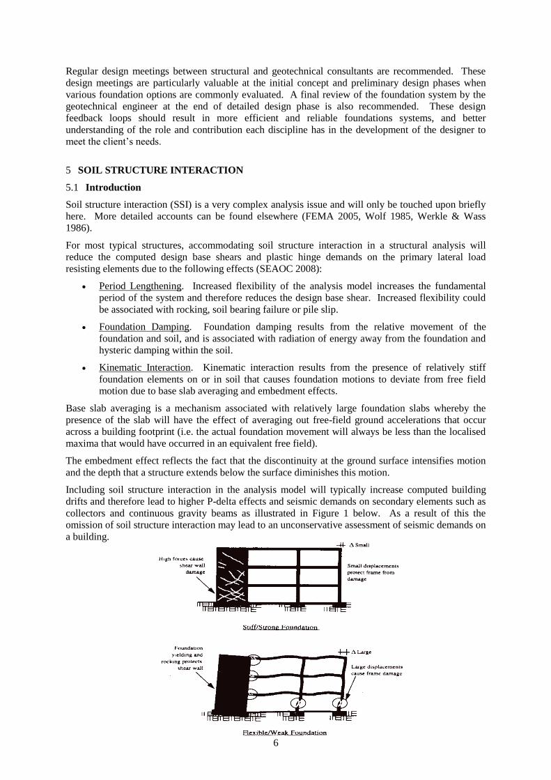
Including soil structure interaction in the analysis model will typically increase computed building
drifts and therefore lead to higher P-delta effects and seismic demands on secondary elements such as
collectors and continuous gravity beams as illustrated in Figure 1 below. As a result of this the
omission of soil structure interaction may lead to an unconservative assessment of seismic demands on
a building.
7
Figure 1 Foundation Flexibility Considerations (Unknown Ref.)
Complexity in analysis is compounded when one considers that the characteristics can be significantly
degraded or otherwise altered by seismic demand – at a time when the soil structure interaction is
“activated”. Careful selection of influential soil parameters and sensitivity analysis is therefore
strongly advised.
5.2 North American Standards
North American building standards such ASCE 41-06 (ASCE 2006) and ASCE 7-10 (ASCE 2010)
contain specific provisions for assessing the effects of soil structure interaction on building
performance. ASCE 41-06 contains design criteria for modelling foundation flexibility, kinematic
effects (i.e. base slab averaging and embedment effects) and foundation damping.
Neither standard requires SSI to be included in structural design. In practice the provisions relating to
kinematic effects and foundation damping are rarely used in North America, and considerable
controversy still exists amongst practicing engineers in terms of their application because of concerns
related to their potential unconservatism.
5.3 Application of North American Standards in the NZ Context
Care is required when adopting design criteria detailed in international building standards and
applying them to New Zealand. The context under which the international design criteria were
established may not be applicable to our loading, or material standards, and as a result may not satisfy
the performance requires of the New Zealand Building Code.
It is the Authors’ opinion that the design criteria for foundation flexibility detailed in Section 4.4 of
ASCE 41-06 are applicable and can be used to assist with the development of structural analysis
models that comply with the requirements of NZS 1170.5. Advice from the geotechnical consultant
should be sought when establishing the necessary soil properties.
Readers are advised against adopting the provisions detailed in ASCE 41-06 and ASCE 7-10 for
kinematic effects and foundation damping. While the use of these design criteria can enable
reductions in seismic design actions of up to 40%, their applicability in New Zealand is questioned.
Aspects of SSI have already been included the NZS1170.5 structural performance factor, Sp, as
described in Section C4.4 of that document. In addition to this the revised NZS1170.5 hazard factor,
Z, for Christchurch was in part calibrated against observed real building performance. Use of the
ASCE 41-06 and ASCE 7-10 kinematic effects and foundation damping provisions might therefore be
considered ‘double-dipping’ and on this basis should be avoided. Notwithstanding this, if more
detailed investigation of kinematic effects and foundation damping are attempted, it is critical that the
secondary impacts of increased displacements and rotations are considered in detail.
6 STRUCTURAL MODELLING
6.1 Generic Approaches
Two generic approaches can be used to model foundation systems:
Direct approach whereby a volume of soil is modelled explicitly with the structure and a total
solution is obtained from a single analysis.
Indirect approach whereby the properties of the underlying soils are derived and idealised in a
simplified representation as springs and dampers.
For routine design work the indirect approach is more commonly used when foundation systems are
modelled, due to the high computation cost associated with modelling the soil continuum necessary
for the direct approach. An introduction to modelling methods applicable to the indirect approach is
8
summarised in the follow sections. Consideration of kinematic effects and foundation damping have
been excluded as these are not typically explicitly considered in routine structural analysis models.
6.2 Shallow Foundations
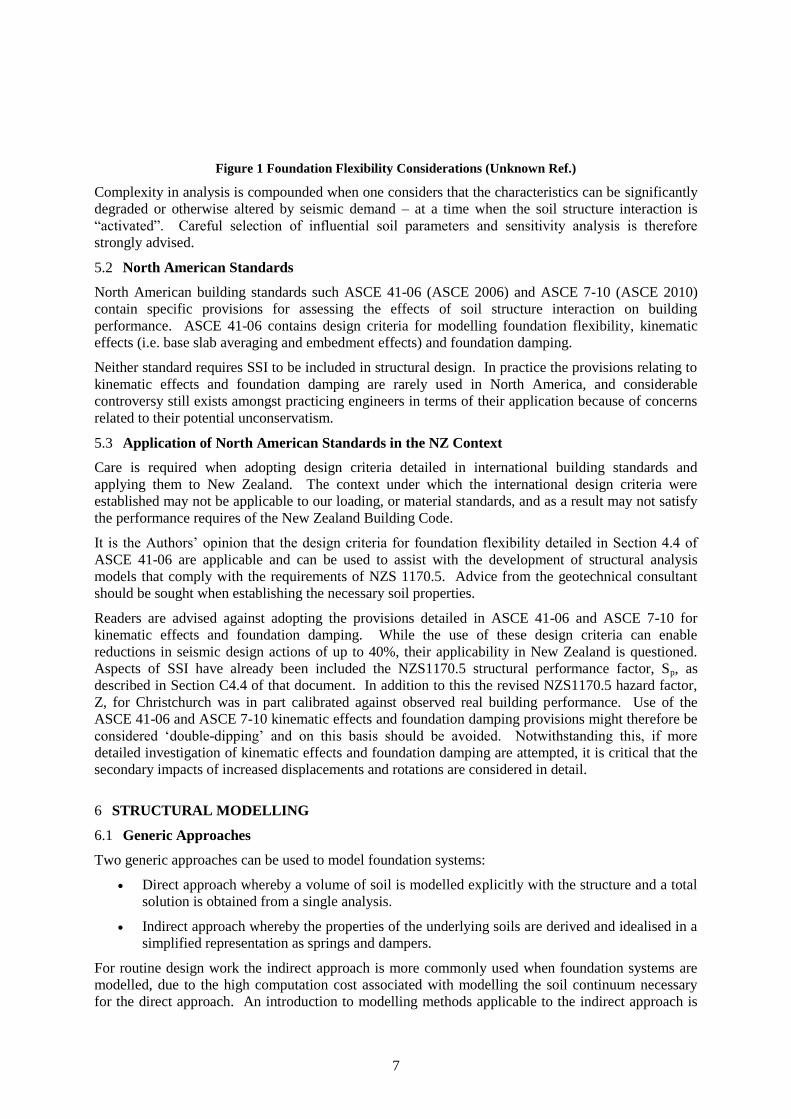
Shallow footings can be idealised using three uncoupled springs (refer Figure 2(b)) or on a bed of
springs using the Winkler spring model (refer Figure 2(c)). The uncoupled spring model is limited to
those applications when the shallow footing is considered to be rigid with respect to the supporting
soils. When this is not the case, the more general Winkler spring model can be used to explicitly
include the footing deformations. As a rule, and when applicable, there is a preference for the use of
uncoupled spring models in structural analysis models as these are easier to implement.
(a) Foundation forces (b) Uncoupled spring model (c) Winkler spring model
Figure 2 Idealised analytical models for shallow foundations (FEMA 1997)
A procedure for calculating the soil spring parameters for both spring models is detailed in
ASCE 41-06 (ASCE 2006). The springs are defined by the soil shear modulus, G, and Possion’s ratio,
. Average values should be used for to determine the spring parameters as noted previously in
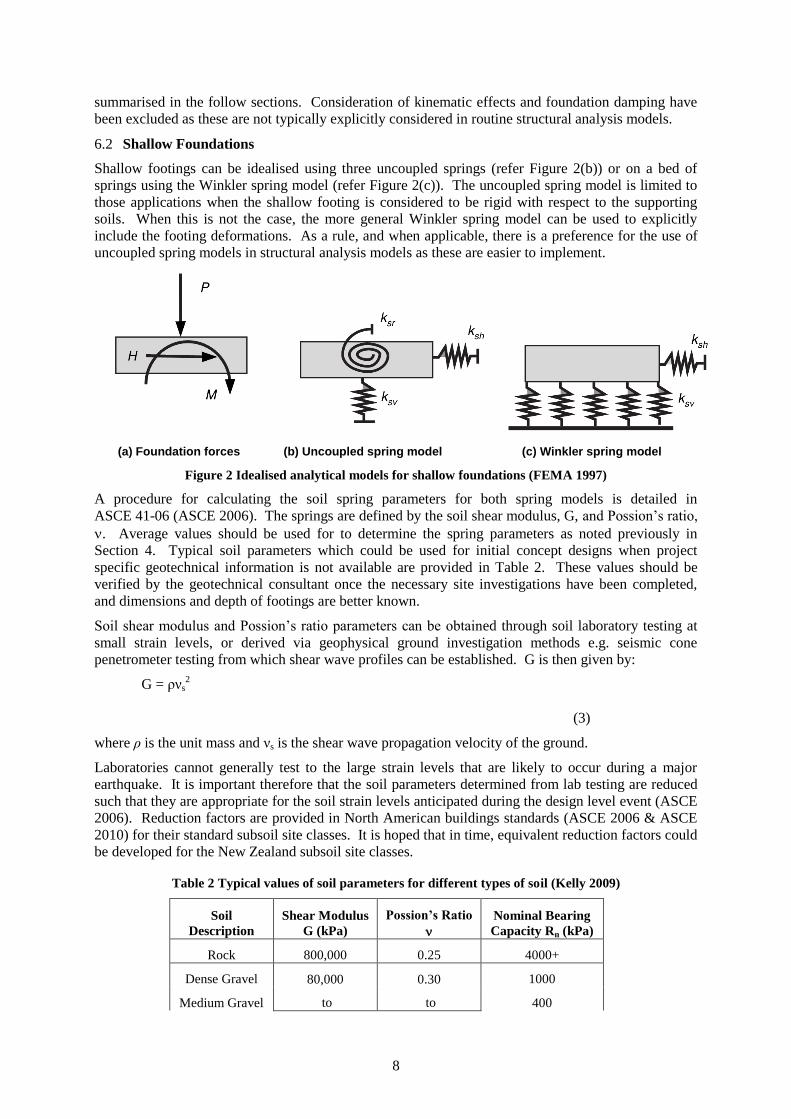
Section 4. Typical soil parameters which could be used for initial concept designs when project
specific geotechnical information is not available are provided in Table 2. These values should be
verified by the geotechnical consultant once the necessary site investigations have been completed,
and dimensions and depth of footings are better known.
Soil shear modulus and Possion’s ratio parameters can be obtained through soil laboratory testing at
small strain levels, or derived via geophysical ground investigation methods e.g. seismic cone
penetrometer testing from which shear wave profiles can be established. G is then given by:
G = ρνs2
(3)
where ρ is the unit mass and νs is the shear wave propagation velocity of the ground.
Laboratories cannot generally test to the large strain levels that are likely to occur during a major
earthquake. It is important therefore that the soil parameters determined from lab testing are reduced
such that they are appropriate for the soil strain levels anticipated during the design level event (ASCE
2006). Reduction factors are provided in North American buildings standards (ASCE 2006 & ASCE
2010) for their standard subsoil site classes. It is hoped that in time, equivalent reduction factors could
be developed for the New Zealand subsoil site classes.
Table 2 Typical values of soil parameters for different types of soil (Kelly 2009)
Soil
Description
Shear Modulus
G (kPa)
Possion’s Ratio
Nominal Bearing
Capacity Rn (kPa)
Rock 800,000 0.25 4000+
Dense Gravel 80,000
to
0.30
to
1000
Medium Gravel 400
9
Dense Sand 40,000 0.4 600
Medium Sand 300
Stiff Clay 20,000 0.5
300
Medium Clay to 2000 150
Typically it will not be feasible to model all shallow foundations with multiple Winkler spring type
models. It is therefore recommended that vertical springs are spaced intermittently along the
longitudinal axis of continuous footings and at the centre of non-moment resisting pad footings
(SEAOC 2008). Use of the more sophisticated Winkler spring foundation models is then limited to
the moment resisting pad foundations that form part of the primary lateral load resisting system.
ASCE 41-06 also provides guidance on when a foundation is considered to be rigid, and therefore,
when the simpler uncoupled spring model can be used.
Soil springs in elastic models that are subject to tension forces should be progressively deactivated in
order to obtain an admissible state of compression only. When nonlinear analysis methods are
employed foundation uplift and soil yielding can be explicitly included in the analysis using gap
elements and nonlinear springs. Again, careful selection of influential soil parameters and sensitivity
analysis is strongly advised.
Lateral capacity of shallow footings can be calculated considering both passive soil pressure and base
friction. Modelling guidance for characterising the lateral deformation response of shallow
foundations is provided in ASCE 41-06. Observations made following the 22nd
February 2011
Christchurch earthquake suggest that the lateral sliding capacities of buildings with shallow
foundations may be significantly higher than that which can be determined using established
principles of soil mechanics. The authors therefore suggest that others be mindful of this when
assessing the likely upper and lower bounds of lateral foundation stiffness.
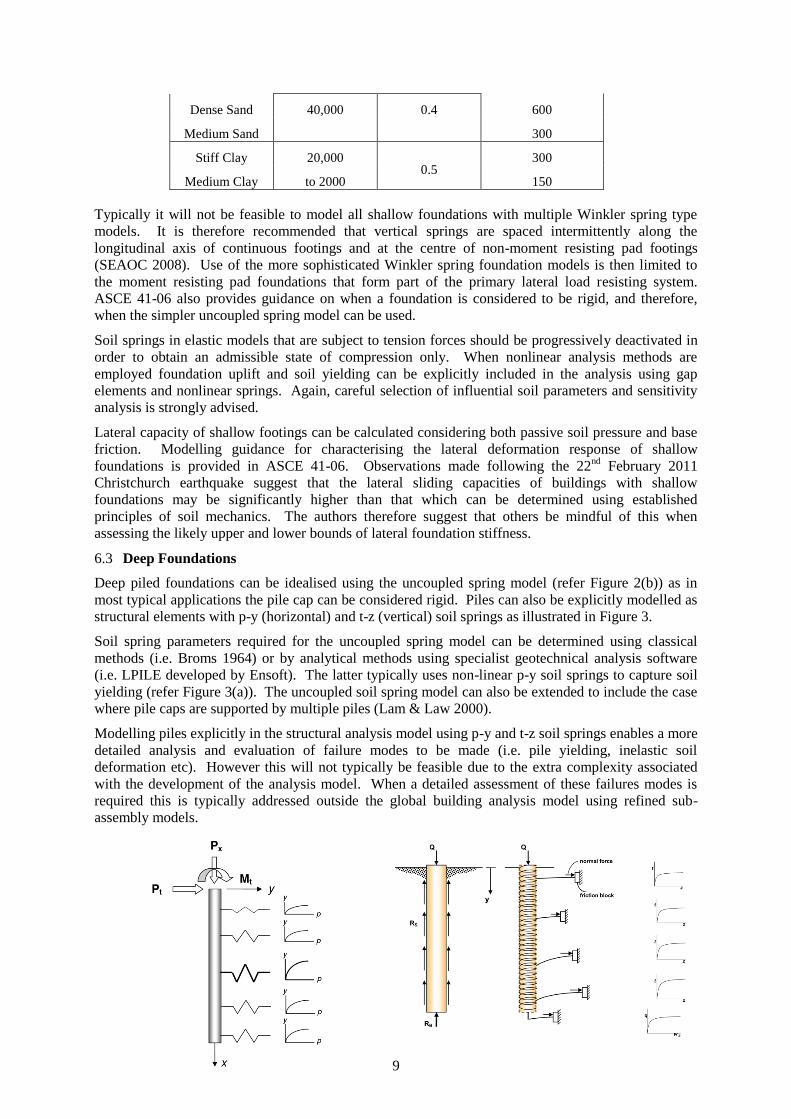
6.3 Deep Foundations
Deep piled foundations can be idealised using the uncoupled spring model (refer Figure 2(b)) as in
most typical applications the pile cap can be considered rigid. Piles can also be explicitly modelled as
structural elements with p-y (horizontal) and t-z (vertical) soil springs as illustrated in Figure 3.
Soil spring parameters required for the uncoupled spring model can be determined using classical
methods (i.e. Broms 1964) or by analytical methods using specialist geotechnical analysis software
(i.e. LPILE developed by Ensoft). The latter typically uses non-linear p-y soil springs to capture soil
yielding (refer Figure 3(a)). The uncoupled soil spring model can also be extended to include the case
where pile caps are supported by multiple piles (Lam & Law 2000).
Modelling piles explicitly in the structural analysis model using p-y and t-z soil springs enables a more
detailed analysis and evaluation of failure modes to be made (i.e. pile yielding, inelastic soil
deformation etc). However this will not typically be feasible due to the extra complexity associated
with the development of the analysis model. When a detailed assessment of these failures modes is
required this is typically addressed outside the global building analysis model using refined sub-
assembly models.
10
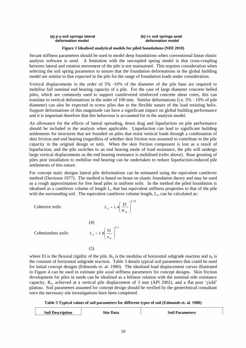
(a) p-y soil springs lateral (b) t-z soil springs axial deformation model deformation model
Figure 3 Idealised analytical models for piled foundations (NHI 2010)
Secant stiffness parameters should be used to model deep foundations when conventional linear elastic
analysis software is used. A limitation with the uncoupled spring model is that cross-coupling
between lateral and rotation movement of the pile is not maintained. This requires consideration when
selecting the soil spring parameters to ensure that the foundation deformations in the global building
model are similar to that expected in the pile for the range of foundation loads under consideration.
Vertical displacements in the order of 5% -10% of the diameter of the pile base are required to
mobilise full nominal end bearing capacity of a pile. For the case of large diameter concrete belled
piles, which are commonly used to support cantilevered reinforced concrete shear cores, this can
translate to vertical deformations in the order of 100 mm. Similar deformations (i.e. 5% - 10% of pile
diameter) can also be expected in screw piles due to the flexible nature of the load resisting helix.
Support deformations of this magnitude can have a significant impact on global building performance
and it is important therefore that this behaviour is accounted for in the analysis model.
An allowance for the effects of lateral spreading, down drag and liquefaction on pile performance
should be included in the analysis when applicable. Liquefaction can lead to significant building
settlements for structures that are founded on piles that resist vertical loads through a combination of
skin friction and end bearing (regardless of whether skin friction was assumed to contribute to the pile
capacity in the original design or not). When the skin friction component is lost as a result of
liquefaction, and the pile switches to an end bearing mode of load resistance, the pile will undergo
large vertical displacements as the end bearing resistance is mobilised (refer above). Base grouting of
piles post installation to mobilise end bearing can be undertaken to reduce liquefaction-induced pile
settlements of this nature.
For concept static designs lateral pile deformations can be estimated using the equivalent cantilever
method (Davisson 1977). The method is based on beam on elastic foundation theory and may be used
as a rough approximation for free head piles in uniform soils. In the method the piled foundation is
idealised as a cantilever column of length Ls that has equivalent stiffness properties to that of the pile
with the surrounding soil. The equivalent cantilever column length, Ls, can be calculated as:
Cohesive soils:
25.0
h
sK
EI4.1L
(4)
Cohesionless soils:
2.0
h
sn
EI8.1L
(5)
where EI is the flexural rigidity of the pile, Kh is the modulus of horizontal subgrade reaction and nh is
the constant of horizontal subgrade reaction. Table 3 details typical soil parameters that could be used
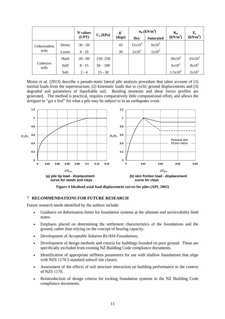
for initial concept designs (Edmonds et. al. 1980). The idealised load displacement curves illustrated
in Figure 4 can be used to estimate pile axial stiffness parameters for concept designs. Skin friction
development for piles in sands can be idealised as a bilinear relation with the nominal side resistance
capacity, Rn, achieved at a vertical pile displacement of 3 mm (API 2002), and a flat post ‘yield’
plateau. Soil parameters assumed for concept design should be verified by the geotechnical consultant
once the necessary site investigations have been completed.
Table 3 Typical values of soil parameters for different types of soil (Edmonds et. al. 1980)
Soil Description Site Data Soil Parameters
11
N values
(CPT) Cu (kPa)
’
(degs)
nh (kN/m3) Kh
(kN/m2)
Es
(kN/m2) Dry Saturated
Cohesionless
soils
Dense 30 - 50 45 15x103 9x10
3
Loose 4 - 10 30 2x10³ 1x10
3
Cohesive
soils
Hard 20 - 60 150- 250 18x103 25x10
3
Stiff 8 - 15 50 – 100 6x10³ 8x10
3
Soft 2 - 4 15 - 30 1.5x10³ 2x10
3
Moniz et al. (2013) describe a pseudo-static lateral pile analysis procedure that takes account of (1)
inertial loads from the superstructure, (2) kinematic loads due to cyclic ground displacements and (3)
degraded soil parameters of liquefiable soil. Bending moments and shear forces profiles are
generated. The method is practical, requires comparatively little computational effort, and allows the
designer to “get a feel” for what a pile may be subject to in an earthquake event.
(a) pile tip load - displacement (b) skin friction load - displacement curve for sands and clays curve for clays
Figure 4 Idealised axial load displacement curves for piles (API, 2002)
7 RECOMMENDATIONS FOR FUTURE RESEARCH
Future research needs identified by the authors include:
Guidance on deformation limits for foundation systems at the ultimate and serviceability limit
states.
Emphasis placed on determining the settlement characteristics of the foundations and the
ground, rather than relying on the concept of bearing capacity.
Development of Acceptable Solution B1/AS4 Foundations.
Development of design methods and criteria for buildings founded on poor ground. These are
specifically excluded from existing NZ Building Code compliance documents.
Identification of appropriate stiffness parameters for use with shallow foundations that align
with NZS 1170.5 standard subsoil site classes.
Assessment of the effects of soil structure interaction on building performance in the context
of NZS 1170.
Reintroduction of design criteria for rocking foundation systems in the NZ Building Code
compliance documents.
0
0.2
0.4
0.6
0.8
1
1.2
0 0.02 0.04 0.06 0.08 0.1 0.12 0.14
0
0.2
0.4
0.6
0.8
1
1.2
0 0.01 0.02 0.03 0.04
Ru/Rn Ru/Rn
z/Dpile z/Dpile
Residual skin friction varies
12
Development of design guidelines that enable designers to avoid unnecessary work by
filtering out secondary effects for particular structures and ground conditions, thus aiding the
designer to quickly identify and focus on the key design issues. This is particularly
important when tackling the complex topics of seismic design of foundations and evaluating
the influence of soil structure interaction on a design.
8 CONCLUSIONS
This article provides an overview of key geotechnical and structural engineering issues related to the
design and analysis of foundation systems. Compliance gaps in existing NZ building code documents
are identified. It is suggested that there is an increased need for communication between structural
and geotechnical engineers to ensure that foundation system designs perform as intended.
Aspects of soil structure interaction have been introduced. Concerns were identified with respect to
validity of applying soil structure interaction design criteria contained within international building
standards to the New Zealand design office context. New Zealand code requirements to include
foundation flexibility in building analysis models were highlighted. Modelling techniques which can
be used by structural engineers in global building analysis models for shallow and deep foundations
were summarised. Recommendations were made for future research needs related to foundation
systems.
9 REFERENCES
ASCE 2010. ASCE 7-10 Minimum Design Loads for Buildings and Other Structures, American Society of Civil Engineers, Reston, VA
ASCE 2006. ASCE 41-06 Seismic Rehabilitation of Existing Buildings, American Society of Civil Engineers, Reston, VA
Broms, B. 1964. The Lateral Resistance of Piles in Cohesive Soils, Journal of Soil Mechanics Found. Div., ASCE, Vol. 90, pp. 27-63.
Edmonds, F.D., Carr, A.J., Goldsmith, P.R., North, P.J., Wood, J.H. & Preston, R.L. 1980, Seismic Design of Bridges Section 4 – Bridge Foundations, Bulletin of NZSEE Vol 13, No 3, Wellington, New Zealand
Davisson, M.T., 1977, Simplified Method foe Evaluating Soil-Pile-Structure Interaction Effects, Technology Conference, Houston, TX, Vol 2, Paper OTC 2954
CEN 2004, Eurocode 8: Design of structures for earthquake resistance -Part 5: Foundations, retaining structures and geotechnical aspects, European Committee for Standardisation, Brussells
DBH 2011, Compliance Document for the New Zealand Building Code – Clause B1 Structure, Department of Building & Housing, Wellington, New Zealand
FEMA 1997. FEMA 274 NEHRP Commentary on the Guidelines for the Seismic Rehabilitation of Buildings, Federal Emergency Management Agency, Washington, DC.
FEMA 2005. FEMA 440 Improvement of Nonlinear Static Seismic Analysis Procedures, Federal Emergency Management Agency, Washington, DC.
Harwood, N. K., 2012 A Review of Shallow Foundation Design Practice in New Zealand. Inaugural SESOC Biennial Conference From Theory To Practice, 2-3 November 2012, Auckland.
Lam, I.P. & Law, H, 1996 Soil-Foundation-Structure Interaction –Analytical Considerations by Empirical p-y Method, Proceedings 4
th Caltrans Seismic Research Workshop, Sacremento, July 9-11.
Moniz, S. R, Harwood, N. K. & Poulos, H. G. 2013, A Pragmatic and Non-Intrusive Procedure for Assessing the Post-Earthquake Structural Integrity of Piled Foundations, NZSEE Technical Conference, Same Risks – New Realities, April 26-28 2013, Wellington
NHI 2010, Drilled Shafts: Construction Procedures and LRFD Design Methods, National Highways Institute Publication No. FHWA-NHI-10-016, Washington DC
NIST 2010. Nonlinear Structural Analysis for Seismic Design – A Guide for Practicing Engineers, National Institute of Standards and Technolgy, Gaithersburg, MD 20899.
SEAOC 2008. SEAOC Blue Book – Seismic Design Recommendations Foundation Modelling, Structural

13
Engineers Association of California, Sacramento, CA.
SNZ 1999, NZS 3604 Timber Framed Buildings, Standards New Zealand, Wellington, NZ
SNZ 2004, 2004, NZS 1170.5 Structural Design Actions Part 5: Earthquake Actions – New Zealand, Standards New Zealand, Wellington, NZ
SNZ 2006, NZS 3101 Concrete Structures Standar, Standards New Zealand, Wellington, NZ
Wolf, J.P. 1985.Dynamic Soil Structure Interaction, Prentice Hall, Englewood Cliffs, NJ
Werkle, H. & Waas, G. 1986, Dynamic Stiffness of Foundations on Inhomogeneous Soils, Proceedings of the 8th
European Conference on Earthquake Engineering, Lisbon, Portugal.