softwaredesignbasic(teachingpendanttransfer)1
TRANSCRIPT

8/3/2019 SoftwareDesignBasic(TeachingPendantTransfer)1
http://slidepdf.com/reader/full/softwaredesignbasicteachingpendanttransfer1 1/32
Classificationnumber
504C3027
Pages 33
Version 1.1Distribution
number1
Design standard document
(Teaching pendant - Transport)
22nd September 2011
Distributionnumber
1 2 3 4 5
Destination
Systemdevicepart 1design
Distributionnumber
6 7 8 9 10
Destination
TAZMO Ltd.
Approvedby
Examinedby
Draft

8/3/2019 SoftwareDesignBasic(TeachingPendantTransfer)1
http://slidepdf.com/reader/full/softwaredesignbasicteachingpendanttransfer1 2/32
Classificationnumber
504C0000
Software BusinessProcedures
(System equipment)Revision history
Page
0 Version 1.10
Tazmo Ltd.

8/3/2019 SoftwareDesignBasic(TeachingPendantTransfer)1
http://slidepdf.com/reader/full/softwaredesignbasicteachingpendanttransfer1 3/32
HistoryNo
Establishment/lastrevised
Itemnumber
(page)Revision description
Approval
Checked
Proposal
1.111/09/22
All pages New establishment Yamano
beKohat
a Yamaz
oe
Tazmo Ltd.
ClassificationNumber
504C3027 Design Standards
(Teaching Pendant)Revision History
Page
1 Version 1.1

8/3/2019 SoftwareDesignBasic(TeachingPendantTransfer)1
http://slidepdf.com/reader/full/softwaredesignbasicteachingpendanttransfer1 4/32
Tazmo Ltd.
ClassificationNumber
504C3027 Design Standards
(Teaching Pendant)Revision History
Page
2 Version 1.1

8/3/2019 SoftwareDesignBasic(TeachingPendantTransfer)1
http://slidepdf.com/reader/full/softwaredesignbasicteachingpendanttransfer1 5/32

8/3/2019 SoftwareDesignBasic(TeachingPendantTransfer)1
http://slidepdf.com/reader/full/softwaredesignbasicteachingpendanttransfer1 6/32
1. General rules1.1. Purposes
This standard document establishes the design criteria of the teaching pendant
operation method of a TAZMO conveying machine, and aims at unification of the
teaching pendant operation method between equipments.
1.2. Scope of applicationThis document is applied for the conveying machine (mainly robots, aligners, loaders,
unloaders) manufactured by TAZMO. When there is no particular request from the user,
the manual for any neighbor teaching pendant will be prepared following this standard.
However,it is not that limitation when applying this standard document to equipment
composition is difficult.
1.3. Establishment-abolition, maintenance managementProvided in a "quality documentation administrative provision", performs
establishment and revision, and maintenance management.
2. Terminologies Industrial robots
Machines which have the ability to move through automatic control or
manipulation functions, can perform various tasks by programs, and are used in
industry.
Manipulator
Machines constituted from segments connected mutually, which aim at holding ormoving objects (parts, tools, etc.).
Operator
Those who carry out with a robot or a robot-system, are recognized as who can
start, supervise and stop the operation.
Rectangular Robot (Cartesian-Coordinated Robot)
The mechanical structure of an arm is mainly a robot of rectangular-coordinates
form.
Cylindrical Robot (Cylindrical-Coordinated Robot)
The mechanical structure of an arm is mainly a robot of cylinder coordinates form.
SCALAR RobotThe mechanical structure of the arm joints has parallel axes of rotation of the
robot in compliance with a plane perpendicular to the axis.
Link
The machine structure or individual rigid element which is relatively movable to
each other.
Degrees of freedom
The number of independent variables required to describe movement of a rigid
body in space.
Motion space
The region that can be swept by moving parts of the robot (any end effector is not
included) Maximum space
The moving space, plus the working region that can be swept by end effectors.
ClassificationNumber
504C3027 Design Standards
(Teaching Pendant)
Page
3 Version 1.1

8/3/2019 SoftwareDesignBasic(TeachingPendantTransfer)1
http://slidepdf.com/reader/full/softwaredesignbasicteachingpendanttransfer1 7/32
Restricted space
The region restricted by the limit equipment which does not exceed in a part of
maximum space no matter failure and malfunction what may arise in a robot
system. Operating space
Distance or angle ready for each axis.
Teaching
Point to a position and store information required in order to do work in a robot.
Direct teaching
People need to move a robot's arm, a hand, etc. directly and teach them.
Remote teaching
A kind of direct teaching, use a pendant etc., and move and teach a robot's arm, a
hand, etc.
Operation modeOperating status of the robot controller.
Automatic mode
An operation mode which controls a robot according to a set-up task program.
Manual mode
An operation mode which has priority over other modes, operating a robot by an
operator.
Pendant
The portable unit which is connected to a control device and performs teaching
operation to a robot in a program.
Simple speed
Speed of the point specified when the single axis operated. Track speed
Velocity along the path.
PTP Control
The control for moving the tool center point of a robot axis to another point,
there’s no specification received about the route in that case.
CP Control
Control performed by the instruction given all orbitals or the entire route.
Interpolation
The function which carries out continuous movement without stopping point given
at intervals.
Stop category
Stop function of the mechanical drive. Be classified into following three
categories.
・Stop category-0:
The stop performed by turning off a machine actuator directly, and is not
controlled. Electronic logic and the software must not intervene.
・Stop category-1:
The stop in which the machine actuator is stopped and the power supply is
stopped after that, controlled by orders from a control circuit. The stop of power
supply must not pass electronic logic and the software.
・Stop category-2: The stop by which power supply is carried out at a machine actuator.
ClassificationNumber
504C3027 Design Standards
(Teaching Pendant)
Page
4 Version 1.1

8/3/2019 SoftwareDesignBasic(TeachingPendantTransfer)1
http://slidepdf.com/reader/full/softwaredesignbasicteachingpendanttransfer1 8/32
Acceleration-Deceleration Control
There are a velocity-trapezoid system which uses constant acceleration as shown
in Fig. 1.1 (a), and makes acceleration a trapezoid; and an S character
acceleration-and-deceleration system which makes acceleration a curve as shownin Fig. 1.1 (b), and uses S-curve acceleration.
(a) Veloci (a) Velocity trapezoid method (b)S-curve acceleration
method
Figure 2.1 Acceleration method
Initial speed
The speed at the start of acceleration and or at the end of deceleration (START inFigure 1.1)
Maximum speed
When acceleration of the acceleration control is finished, the speed reaches the
constant speed range (MAX in Figure 1.1).
Acceleration
The amount of change of velocity per time during acceleration and deceleration of
acceleration and deceleration control (ACC in Figure 1.1).
S-curve ratio
The ratio of straight line acceleration part (S1) at the time of acceleration of an
acceleration trapezoid system, and the S-curve acceleration part (S0-S1). From
the figure, it becomes((S0-S1)/S0*100)(%).
3. Robot safety requirement items3.1. General industrial robots
When equipped with industrial robots (the definition of an industrial robot is referring
to the following), priority is given to Industrial Safety and Health Act, cope with it to
meet the following safety standards.
Definition: When it corresponds to all the followings, consider it as an industrial
robot.
(1) Having a driving source exceeding 80W. If you have more than one drive
source, it is considered the maximum output of them.(2) Having a manipulator and a memory storage
(3) Performing at least 2 operations of stretching, left-right, up-down.
ClassificationNumber
504C3027 Design Standards
(Teaching Pendant)
Page
5 Version 1.1
ACC
M A X
S T AR T
S P E ED
T IM E
ACCS 0S 1
M A X
S T A R T
S P E ED
T IM E

8/3/2019 SoftwareDesignBasic(TeachingPendantTransfer)1
http://slidepdf.com/reader/full/softwaredesignbasicteachingpendanttransfer1 9/32
(4) The motion space of a manipulator exceeds the range of either of four kinds
of the following.
a. 300mm radius x 300mm long for cylindrical-coordinated robot
b. 300mm radius for spherical-coordinated robotc. 300mm x 300mm long for rectangular robot
d. 100mm vertical distance for vertical and horizontal operation.
3.2. Emergency stop-irregular stopWhen the emergency stop operates, the mechanical operation is made into the
mechanism which can stop immediately (stop category 0).
3.3. Teaching(
1)
When a robot is in teaching mode, it is automatically set to safe workingspeed..
(2) Safe working speed of 250 mm/sec (path velocity)or less.
(3) The teaching operation of a robot is performed only while pushing the push-
button switch (Enabling SW).
(4) When the teaching device (pendant) needs to perform teaching operation, a
power supply interception button switch (Stop SW) should be installed to the
pendant.
(5) When you are operating in manual mode, do not perform any operation from
the outside into the structure unless there is the emergency stop switch.
(6) Display the purport of teaching operation with indicating lights etc. during
teaching work.(7) Those who is working with industrial robots should carry out safety rules.
Note: Health Law Article 59 Paragraph 3 (No. 31 Article 36 of the Occupational
Health and Safety regulations, No. 32), Article 18 of the safety and
health regulations established by the special education and training
course is based on Article 19 "special education instructor for industrial
robots", don't perform safety education for those who is non-qualified.
ClassificationNumber
504C3027 Design Standards
(Teaching Pendant)
Page
6 Version 1.1

8/3/2019 SoftwareDesignBasic(TeachingPendantTransfer)1
http://slidepdf.com/reader/full/softwaredesignbasicteachingpendanttransfer1 10/32
4. Teaching pendant Name: Small Pendant
Model: HG1T-SB12UH-MK1444
Manufacturer: IDEC Corporation Interface( You cannot modify the settings below)
Communication form: RS232CCommunication speed: 9600bpsData bit: JIS8Parity: NoneStop bit: 1XON/XOFF Control: Disable(no control)Local echo: Disable(no control)CR operation code: Cr(recovery operation only)Buzz Key: No(Beep)
Figure 4.1 Pendant figure
ClassificationNumber
504C3027 Design Standards
(Teaching Pendant)
Page
7 Version 1.1
A u t om a t i c m o d e
M a n u a l m o d eS t o p SW
X →← X ↓ Z Y →← Y
→←
C ANOK
B S
EN T
C L R
+ / -SH I F T 0
98
6
3
5
2
.
1
4
7
S TO POR G↑ ZFUNCE SC
F 1 0F 9F 8F 7F 6
S e l e c t o r SW
8 x 3 2 c o l um n s
9 x 5 c o l um n sM em b r a n e SW
LC D d i s p l a y
E n a b l i n g SWF 5F 4F 3F 2F 1

8/3/2019 SoftwareDesignBasic(TeachingPendantTransfer)1
http://slidepdf.com/reader/full/softwaredesignbasicteachingpendanttransfer1 11/32
(1) LCD display
The LCD display has 8 rows of 32 digits.
(2) Stop SW
By pressing the stop switch, the motor drive power supply is cut all off. RESETstop switch (turn slightly to the right) to release it.
(3) Selector SW
Switching between automatic and manual modes. When it is turned down, the
automatic mode is selected, when turned up, the manual mode is selected.
(4) 3-position enabling SW(Enabling SW)
When operating in manual mode, a drive power supply is switched on and it can
operate. If this key is released, a drive power supply is cut off. It is ignored in
automatic mode. Since it is a 3-position switch, when operating it, please press
this key lightly. A switch will be come by off if pushed in strongly.
(5
)Key input unit
(Membrane SW
)
It is used for an input or an operation of equipment from a pendant.
5. Concept of the teaching pendantTeaching pendant are used for robot operations, there are automatic and manual
modes, selected via the selector switch on the teaching pendant. In automatic mode,control operates from the top, you cannot teach pendant operation (monitor functionsonly). In manual mode, operates under the control of the teaching pendant, cannot becontrolled from the top (only read status command).Each command is grouped by using features, and a hierarchy (a tree of functions). Eachoperation also has a password-protection, and that differentiation is made.
5.1. Password on entry The password at the entry of a teaching pendant has just two modes, User mode and
Tazmo mode. However, this is not limited if the user requires more.(1)Password type
The following 2 password modes are prepared. Changing a pre-set password isimpossible.●User Mode: 9784(the password open to a user)●Tazmo Mode: 6809、9600(not open to a user)●Error release Mode:9999(not open to a user)
(2)Password level●User mode:for the user、when a user operates it, a pertinent portion is made
with basic functions and private security.●Tazmo Mode : for Tazmo, which can access the full functionality (runningoperation, speed parameter settings, etc.)●Error release Mode: Error surveillance is stopped and pendant operation isenabled. Suppose that manual operation of an operation category is impossible. A password screen is displayed after power activation, the screen is eitherautomatic mode or manual mode in respect to the selection switch (refer to Fig.5.1 and Fig. 5.2). MODEL:Model name VER :Software version PON:Program number of software
ClassificationNumber
504C3027 Design Standards
(Teaching Pendant)
Page
8 Version 1.1

8/3/2019 SoftwareDesignBasic(TeachingPendantTransfer)1
http://slidepdf.com/reader/full/softwaredesignbasicteachingpendanttransfer1 12/32
12345678901234567890123456789012
Figure 5.1 Password screen in automatic mode
12345678901234567890123456789012
Figure
5.2 Password screen in manual mode
(3)How to enter passwordClear Key[CLR]・・・・・・・・・Clear the passwordBackspace Key[BS]・・・・・・Delete a password characterEnter Key[ENT]・・・・・・・・Enter passwordNumeric Keys[0]~[9]・・・・・・・・Password input
(4)When a wrong password is enteredIf the password is wrong, characters appear in line 8 as below:「PASSWORD IS INCORREC」Enter Key[ENT]・・・・・・・・Retype the password
[UNIT INFORMATION] |REMOTEMODEL:***** |VER :*.** |PNo. :********* |
|[INPUT PASSWORD] |PASSWORD:******** |
|
[UNIT INFORMATION] | TEACHING
MODEL:***** |VER :*.** |PNo. :********* |
|[INPUT PASSWORD] |PASSWORD:******** |
|
ClassificationNumber
504C3027 Design Standards
(Teaching Pendant)
Page
9 Version 1.1

8/3/2019 SoftwareDesignBasic(TeachingPendantTransfer)1
http://slidepdf.com/reader/full/softwaredesignbasicteachingpendanttransfer1 13/32
6. Basic operation of the Teaching PendantIn order to make it equivalent to traditional pendant (PF820), 20 digits are used from
the left; another 12 digits are used from the right, showing operation mode on the 1 st
line, and the operation unit on the 2nd line, and arbitrary use on lower ones. Forreference, the example is shown in Figure 6.2.
12345678901234567890123456789012
Figure 6.1 Basic operation screen
Figure 6.2 Right screen example
Operations of the teaching pendant are divided in to the follow five, which are thestandards of operation of this. The screen display’s main title is on the first line and in []brackets.
[**********] */*|MODE1.************* |UNIT
2.************* |3.************* |4.************* |5.************* |6.************* |7.************* |
[**********] */*|MODE1.************* |UNIT2.************* |MANUAL3.************* |TAZMO4.************* |OVERRIDE5.************* |READY!!6.************* |SPEED *7.************* |ALARM:****
ClassificationNumber
504C3027 Design Standards
(Teaching Pendant)
Page
10 Version 1.1
The lower 6lines are not
specified
Align operations
The top 2lines: Statusdisplay
Password level
Sensor override
Power ready
Type of operation
Currently set speed
Alarm is occurring
Main title

8/3/2019 SoftwareDesignBasic(TeachingPendantTransfer)1
http://slidepdf.com/reader/full/softwaredesignbasicteachingpendanttransfer1 14/32
6.1. Select the item (for example, when selecting the command) Among the items that are displayed on the screen, you choose what you want to
work.
(1)Screen displayItem selection on the same menu layer is performed by the numeric keys [1] ~[7]. The screen just displays buttons and items which are available. Numberkeys are separated by periods (.). Also, if there are more than seven choices, itdisplays according to the arrangement (see below) of screen page scrolling. A keystroke is performed to select the item、carried out by numeric keys( 1~7).(In item selection, do not use numeric key of 8 or more)
(2)Operation methodsNumeric Keys[1]~[7]・・・・・・・・・ Item selection、move to lowermenu layers.Cursor Keys ← →[ ]、[ ]・・・・・・・・Switch between pages
Escape Keys[ESC]・・・・・・・・Move to the upper menu layers.
(3)Cursor displayNo cursor is displayed in an item selection menu.
12345678901234567890123456789012
Figure 6.3 Item selection screen
[TITLE] */*|MODE1.********** |UNIT2.********** |3.********** |4.********** |
5.********** |6.********** |7.********** |
ClassificationNumber
504C3027 Design Standards
(Teaching Pendant)
Page
11 Version 1.1

8/3/2019 SoftwareDesignBasic(TeachingPendantTransfer)1
http://slidepdf.com/reader/full/softwaredesignbasicteachingpendanttransfer1 15/32
6.2. Input data(such as time teaching)Parameter settings such as teaching or performing direct input of numeric data.(1)Screen display
It is desirable to display the data and the range of data being set at the time of entering data.
(2)Operation methodsClear Key[CLR]・・・・・・・・・Clear input lineBackspace Key[BS]・・・・・・Delete one input characterEscape Key[ESC]・・・・・・・Return data from the input mode(input) Move to the upper menu layer ( inputselection)Enter Key[ENT]・・・・・・・・Data inputNumeric Key[0]~[9]・・・・・・・・Input selection[1]~[7] Numeric data entry[0]~[9]
Period Key[・]・・・・・・・・・・Floating-point data entryPositive/Negative Key[+/-]・・・・・・Toggle the sign of the data
(3)Item selection and cursor displayIf an item is chosen by a number key, a cursor will be displayed on the portionwhich requires an input. In the case of a selection item, selection items aredisplayed one by one. (Example: YES<=>NO)
12345678901234567890123456789012
Figure 6.4 Data entry screen
6.3. The confirmation page ( for example, when running thecommand)
Command execution and data changes require confirmation. The confirmationscreen will be displayed at this time.
(1)Screen displayThe title and operation keys are displayed.
(2)Operation methodsOK Key[OK]・・・・・・・・RunCancel Key[CAN]・・・・・・Cancel(go back to the original)Enter Key[ENT]・・・・・・・OK Escape Key[ESC]・・・・・・Cancel(go back to the original)
(3)Cursor displayThe confirmation screen doesn’t display the cursor.
[TITLE] */*|MODE1.****** : **.** |UNIT2.****** : **.** |
3.****** : **.** |4.****** : **.** |5.****** : **.** |6.****** : **.** |7.****** :*** |
ClassificationNumber
504C3027 Design Standards
(Teaching Pendant)
Page
12 Version 1.1
8/3/2019 SoftwareDesignBasic(TeachingPendantTransfer)1
http://slidepdf.com/reader/full/softwaredesignbasicteachingpendanttransfer1 16/32
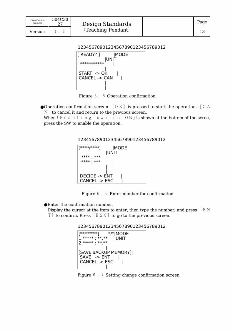
12345678901234567890123456789012
Figure 6.5 Operation confirmation
●Operation confirmation screen.[OK] is pressed to start the operation.[CA
N]to cancel it and return to the previous screen.
When「Enabling switch ON」is shown at the bottom of the scree,
press the SW to enable the operation.
12345678901234567890123456789012
Figure 6.6 Enter number for confirmation
●Enter the confirmation number.
Display the cursor at the item to enter, then type the number, and press [EN
T]to confirm. Press[ESC]to go to the previous screen.
12345678901234567890123456789012
Figure 6.7 Setting change confirmation screen
[ READY? ] |MODE|UNIT
*********** ||
START -> OK |CANCEL -> CAN |
||
[****/****] |MODE|UNIT
**** : *** |**** : *** |
||
DECIDE -> ENT |CANCEL -> ESC |
[********] */*|MODE1.***** : **.** |UNIT2.***** : **.** |
|[SAVE BACKUP MEMORY]|SAVE -> ENT |CANCEL -> ESC |
|
ClassificationNumber
504C3027 Design Standards
(Teaching Pendant)
Page
13 Version 1.1

8/3/2019 SoftwareDesignBasic(TeachingPendantTransfer)1
http://slidepdf.com/reader/full/softwaredesignbasicteachingpendanttransfer1 17/32
●Setting checking screen. Under the current screen, five lines is displayed, as
shown in the above figure, and all of a numerical value and an item are saved.
[OK]to save the backup memory, and to return to the menu.[CAN]to go to
the original menu.
12345678901234567890123456789012
Figure 6.8 Running screen
●Screen during operation.
During the operation, press and hold SW to enable, and release to stop
6.4. JOG operation screenIt is operated in JOG or JOG teaching.
(1)Screen displayThe display of an axis and the operation of each axis in JOG operation areperformed. Moreover, input operation is performed in JOG teaching.
(2)Operation methods
数字キー[1]~[7]・・・・・・・・・・Choose the axisCursor Keys ↑ ↓[ Z][ Z]・・・・・・・ Axis selectionCursor Keys ← →[ ][ ]・・・・・・・・・Low speed JOG operationCursor Keys ← →[ Y][Y ]・・・・・・・High speed JOG operationEnter Keys[ENT]・・・・・・・・・・OK
(3)Item selection and cursor displayItem selection is performed by numeric keys [ 1 ] ~ [ 7 ] , and ↑ ↓[ Z ] [Z]for scrolling selection. The selected item is highlighted.While holding the enabling SW, press ← → ← →[ ] [ ] [ Y ] [ Y ] for JOGoperation to be performed. Either →[ ] or →[ Y ] is for positive direction、
←[ ] or ←[ Y]for negative direction.Low-speed JOG runs at speed number 1.
High-speed JOG runs at speed number 2.
12345678901234567890123456789012
Figure 6.9 JOG operation screen
|MODE|UNIT
************ ||
EXECUTING!! ||||
[****] */*|MODE1.******* |UNIT2.******* |3.******* |4.******* |5.******* |6.******* |7.******* |
ClassificationNumber
504C3027 Design Standards
(Teaching Pendant)
Page
14 Version 1.1

8/3/2019 SoftwareDesignBasic(TeachingPendantTransfer)1
http://slidepdf.com/reader/full/softwaredesignbasicteachingpendanttransfer1 18/32
6.5. Error screenWhen an error occurs, the error status is displayed.(1)Screen display
When an error occurs, if it is able to continue, the screen in Figure 6.10 isdisplayed, if not, the screen in Figure 6.11 is displayed.For a continuation possible error, the error can be canceled bygenerating 「 ENT」 key.For a continuation impossible error, press 「 ENT」 toremove the error and perform a CPU reset.
(2)Operation methodsEnter Key[ENT]・・・・・・・・・・Clear the error, reset CPU
(3)Item selection and cursor displayCursor display is not performedSince pendant operation cannot be performed in a continuation impossible
error, error release may not be able to be carried out. In order to prevent it, anerror screen is not displayed for 5 seconds after a power supply injection. Thepassword in error release mode is entered between them.
12345678901234567890123456789012
Figure 6.Error 10 occurrence screen (able to continue)
12345678901234567890123456789012
Figure 6.Error 10 occurrence screen (unable to continue)
***: Error Code(3 characters)XXXXXXXXXXXXX: Error Message(maximum 16 character)
[ERROR] |MODE|UNIT
***:XXXXXXXXXXX |||
CONTINUE -> ENT ||
|
[ERROR] |MODE|UNIT
***:XXXXXXXXXXX |||
CPU RESET -> ENT |
POWER OFF ||
ClassificationNumber
504C3027 Design Standards
(Teaching Pendant)
Page
15 Version 1.1

8/3/2019 SoftwareDesignBasic(TeachingPendantTransfer)1
http://slidepdf.com/reader/full/softwaredesignbasicteachingpendanttransfer1 19/32
7. About screen(1)Scroll the screen page
Screen at the same hierarchical level can be made in the initial screen. The
following page is created when a display cannot be performed. At this time,(the number of pages / the total number of pages) is specified in the screenupper right. Each page can be switched using the cursor keys [←] [→], you cantoggle crossed. ←([ ]:reverse direction, →[ ]: forward direction)
Figure 7.1 Screen scrolling
(2)Display dataIt is based on not outputting "0" on a beam when displaying digital data(Eg) Regular 1234(mm)
False 00001234(mm)
8. Control of teaching pendant8.1. Initial Control of Teaching PendantWhen teaching pendant is starting, it shows initial control. It returns to a password
entry screen by changing a selection switch, and enables operation by another mode of operation, without intercepting power supply. However, the change by that a robot is ahalt condition at the time of a selection switch change and an operating state isforbidden. When pull it out, teaching pendant is stopped and alarm is generated.
8.2. Configure actionsConfigure actions (Operation mode selection → Unit selection → Category selection→ Operation item → Details of an operation item)(Reference figure 8.1).
(1)Operation mode selection“Automatic mode”(REMOTE)and “Manual mode”(TEACHING)can bechosen by selecting a switch of teaching pendant. In the case of “Automatic
mode”, the following categories of actions can only monitor operations(But inTAZMO mode, running is possible).
(2)Unit selectionEach unit is chosen when two or more units operated with a teaching pendantexist. In the case of a single unit, suppose that an abbreviation is possible. A unit name refers to table 8.1 and determines it individually.
Table 8.1 Unit nameUnit name Unit
ALL UNIT All units (Common items)WAFER TRANSFER Transfer robot
ALIGNER AlignerLOADER * Opener *(*:1~4)
(3)Operation category
[TITLE] 1/2|MODE1.****** : **.** |UNIT2.****** : **.** |3.****** : **.** |4.****** : **.** |5.****** : **.** |
6.****** : **.** |7.****** :*** |
[TITLE] 2/2|MODE1.****** : **.** |UNIT2.****** : **.** |3.****** : **.** |4.****** : **.** |5.****** : **.** |
6.****** : **.** |7.****** :*** |
ClassificationNumber
504C3027 Design Standards
(Teaching Pendant)
Page
16 Version 1.1

8/3/2019 SoftwareDesignBasic(TeachingPendantTransfer)1
http://slidepdf.com/reader/full/softwaredesignbasicteachingpendanttransfer1 20/32
According to a teaching pendant, an operation category is classified into thefour following kinds.
Manual(MANUAL)
Work that related to operating. Operation for performing the manual operationof axial movement or auxiliary operation, and setup JOG teaching data.
Parameter(PARAMETER )Operation which writes data to memory. Operation for setting variousparameters.
Monitor(MONITOR )Operation of checking a state. Operation for performing the monitor of aninput-and-output signal or a log.
Running(RUNNING)Operation that a pendant performs individual operation. Operation will becomepossible if it inputs with the password in TAZMO mode from automatic mode.Some items is not displayed in user mode.
In running operation, a sensor override is used and it can be made to performa conveyance check without a work.
Figure 8 .1 Pendant
operation composition
ClassificationNumber
504C3027 Design Standards
(Teaching Pendant)
Page
17 Version 1.1
[UN I T IN FO RM A T ION ]
[ IN PU T P A S SWORD ]P A S SWO RD : * * * *
V E R : * . * *MOD E L : * * * * *
1 . A L L UN I T[UN I T ] 1 / 1
2 .UN I T 13 .UN I T 2
1 .M AMUA L2 . P AR AM E T E R 3 .MON I TOR
[M OD E ] 1 / 1
[UN I T IN FORM A T ION ]
[ IN PU T P A S SWO RD ]P A S SWO RD : * * * *
V E R : * . * *MOD E L : * * * * *
[UN I T ] 1 / 11 . A L L UN I T2 .UN I T 13 .UN I T 2
1 .MON I TOR [MOD E ] 1 / 1
| T E A CH IN G | R EMO T E
| T E A CH IN G | R EMO T E
| T E A CH IN G | R EMO T E|UN I T |UN I T
[M ANU A L ] 1 / * [ P A R AM E T E R ] 1 / * [MON I TO R ] 1 / *| TE ACH ING|UN I T |UN I T
| * * * * * *| T E ACH IN G|UN I T1 . * * *
2 . * * * * *3 . * * *4 . * * *5 . * * * * * * * *6 . * * * * * * *7 . * * * * * * *
1 . * * *2 . * * * * *3 . * * *4 . * * *5 . * * * * * * * *6 . * * * * * * *7 . * * * * * * *
1 . * * *2 . * * * * *3 . * * *4 . * * *5 . * * * * * * * *6 . * * * * * * *7 . * * * * * * *
|
|
|
|
|
|
|
|
|
|
|
|
|
|
|
|
|
|
|
|
|
|
|
|
|
|
|
|
|
|
|
|
|
|
|
|
|
|
|
|
|
|
|
|
|
|
|
|
|
|
|
|
|
|
|
|
|
|
4 .UN I T 35 .UN I T 4
4 .UN I T 35 .UN I T 4
S e l e c t o r SW
T E A CH ING R EM O T EPN O : * * * * * * * * * PNO : * * * * * * * * *
2 .RUNN ING
Operation modeselection
Unit selection
Categoryselection
Categoryselection
Operationitem
Manual mode Automatic
mode
Unitselection

8/3/2019 SoftwareDesignBasic(TeachingPendantTransfer)1
http://slidepdf.com/reader/full/softwaredesignbasicteachingpendanttransfer1 21/32
(4)Operation itemsSelect specified operation item. The item with reference to the following table,corresponding to the individual.
Table 8.2 Operation itemsCategory Item M Detail Content
MANUAL ORG InitializationHOME Move to HOME positionMOVE Station number Move to STOP POINTGET Extract operationPUT Storage operationEXTEND Stretch armRETRACT Retract armHOLD Hold operationRELEASE Release operationLIFT UP Arm PUT start height movementLIFT DOWN Arm GET start height movementLIFT MID Arm teaching start height
movementCHANGER Inversion-axis operationXCHANGE Exchange operationMAPPING Station number Mapping operationMAP MOVE Station number Mapping position movementMAP EXTEND Mapping sensor growthMAPRETRACT
Mapping sensor shrinkage
MAP UP Mapping sensor move upMAP DOWN Mapping sensor move down
ALIGNMENT Alignment startCENTERING Center alignment operation
LDP OPEN Open LOAD PORTLDP CLOSE Close LOAD PORT
JOG Specified for each axis JOG OperationTEACHING Specified for each axis JOG Teaching* ORG SEACH ● Each independent axis Starting point detecting operation
PARAMATER
****COMMUNI
BA RATE Communication baud rate
DATA Data bitsPARITY ParitySTOP Stop bitTIME OV Communication time over
RSP NUM Respone timesRSP TIM Respone time interval
HOMEPOSITION
X POSI X-axis (rect coordinate) homeposition
Y POSI Y-axis (rect coordinate) homeposition
R POSI R-axis (cyl coordinate) homeposition
T POSI θ-axis (cyl coordinate) homeposition
Z POSI Lift axis home positionS POSI Slide axis home positionP POSI Inversion axis home position
STATION STATION No. Station numberX POSI X-axis (rectangular) teaching
position Y POSI Y-axis (rectangular) teaching
position
ClassificationNumber
504C3027 Design Standards
(Teaching Pendant)
Page
18 Version 1.1

8/3/2019 SoftwareDesignBasic(TeachingPendantTransfer)1
http://slidepdf.com/reader/full/softwaredesignbasicteachingpendanttransfer1 22/32
R POSI R-axial (cylinder) teaching positionT POSI θ-axial (cylinder) teaching positionZ POSI Lift axis teaching positionS POSI Slide axis teaching position
P POSI Inversion axis teaching positionUP LIFT Upper lift movementDOWN LIFT Bottom lift movementLIFT STOP Lift stop teaching positionCOMPLE Teaching end
ORG DATA ● X ORG X-axis original offset● Y ORG Y-axis original offset● R ORG R-axis original offset● T ORG θ-axis original offset● Z ORG Lift axis original offset● S ORG Slide axis original offset● P ORG Inversion axis original offset
MOVE SPEED Each speedspecification
Speed of the specified position
STATIONSPEED
STATION No. Station number
ARM EXTEND Arm speed when there is work ARM RETRACT Arm speed when there is no work LIFT LO Low speed of lift position teachingLIFT HI Top speed of lift position teachingMAPPING Mapping speedTEACHING Teaching speed
SPEEDTABLE
● SPEED No. Speed number (each axis)
● MAX Top speed● START Start speed● ACC Acceleration● S CRV S ratio
MAPPING SIZE Work sizeSLOT The number of slots of a cassetteS PITCT Slot width of a cassetteSTROKE Amount of lift mappingEXTENT Existence detection width
operationRANGE Thickness detection width
operationPOINT Mapping detection depth positionFLYOUT Running-out detection positionSEN OFF Difference bt chuck & sensor
positionTIMING GET WAIT GET waiting time
PUT WAIT PUT waiting timeRETRY GET/PUT times of retryEXEC TIM Execute operating time
OVERRIDE GET/PUT existence check issometimes ignored
CONFIGURATION
● * +LIM **Limit position of the axis in thepositive direction
● * -LIM * Limit position of the axis in the
negative direction● ARM LENGTH Arm length● SV INP Servo motor in-position width● ST INP Step motor position gap width
ClassificationNumber
504C3027 Design Standards
(Teaching Pendant)
Page
19 Version 1.1

8/3/2019 SoftwareDesignBasic(TeachingPendantTransfer)1
http://slidepdf.com/reader/full/softwaredesignbasicteachingpendanttransfer1 23/32
DEFAULT ● Data is returned to an initial value ALRAM LOGCLEAR
Clear the alarm log
COMMUN
LOG CLEAR
Clear communication log
MONITOR ERROR LOG Display error logCOMMUNICA TION LOG
Display communication log
INPUT/OUTPUT
I/O display
ENCODER ABS ENCODER Display absolute value of encoderINC ENCODER Display incremental value of
encoder● DEFF COUNT Display deviation value of encoder
CASSETTETEACH
Cassette teaching display
MAPPINGRESULT
Mapping result display
MAPPINGDATA
Mapping data display
RUNNING TRANSFER ● Station specification Transfer operation running ARMRUNNING
● Single arm operation running
TURNRUNNING
● Turn operation running
LIFTRUNNING
● Lift operation running
SLIDERUNNING
● Slide operation running
FLIPRUNNING
● Flip operation running
M(Mode ●): is displayed in TAZMO mode.
9. NotesIn the creating of the teaching pendant software, pay attention to the following
notes:●In the manual mode of a pendant, there are 2 ranks of speed(1 low speed,2 high speed, speed is used to set at 250 mm/s or less.●In the times of a start of operation, such as the time of running or operation,inside of area where operating is being dangerous.
ClassificationNumber
504C3027 Design Standards
(Teaching Pendant)
Page
20 Version 1.1

8/3/2019 SoftwareDesignBasic(TeachingPendantTransfer)1
http://slidepdf.com/reader/full/softwaredesignbasicteachingpendanttransfer1 24/32
10. Appendix An error code may include 4 figures. The first is error level, the following figure is
unit number, lower 2 figure be an error code. When a display is a double figure display,
lower 2 figure is displayed.
Error code: #$**
#: Unit number
$: Error level
**: Error code
Table 10.1 Error code table(2 lower figures)Code Message Content Level
00 RUN Standby state LV001 TEACHING Teaching box operation LV002 READY Moto preparation LV0
03 ACTIVE Running LV004 LV005 LV006 LV007 PAUSE Paused LV008 INTERLOCK Under interlock LV009 INITIAL In preparation LV010 WAIT INITIAL Waiting for untreated initialization LV020 WORK OFF No wafer LV121 WORK ON There is wafer LV122 WORK OFF SLOT No wafer in a specified slot LV123 WORK ON SLOT Specified slot has wafer LV124 SLOT ERROR Error at specified slot LV125 NO STATION No location is specified LV1
26 ARM NO. ERROR Specified arm is abnormal LV127 LV128 LV129 LV12a MAPPING
SENSOR Mapping sensor error LV1
2b MAP PARAMETER Parameter is not set LV12c LV12d LV12e MAP FLYOUT ERR Running out of wafer LV12f MAP DISABLE Stop during mapping LV130 ARM1 OVER Out of range error LV131 ARM2 OVER Out of range error LV132 TURN OVER Out of range error LV133 LIFT OVER Out of range error LV134 SLIDE OVER Out of range error LV135 FLIP OVER Out of range error LV136 RESERVE LV137 RESERVE LV138 ARM1 BATT
WORNBattery of absolute encoder decreased LV1
39 ARM2 BATTWORN
Battery of absolute encoder decreased LV1
3a TURN BATTWORN
Battery of absolute encoder decreased LV1
3b LIFT BATT WORN Battery of absolute encoder decreased LV13c SLIDE BATT
WORN
Battery of absolute encoder decreased LV1
3d FLIP BATT WORN Battery of absolute encoder decreased LV13e RESERVE LV13f RESERVE LV1
ClassificationNumber
504C3027 Design Standards
(Teaching Pendant)
Page
21 Version 1.1

8/3/2019 SoftwareDesignBasic(TeachingPendantTransfer)1
http://slidepdf.com/reader/full/softwaredesignbasicteachingpendanttransfer1 25/32
40 NOT READY Power supply of driver is not switched on LV141 LV142 LV143 LV1
44 LV145 LV146 LV147 LV148 LV149 LV14a LV14b LV14c LV14d LV14e LV14f LV180 BACKUP MEMORY Backup memory error LV3
a0 BEFORE INITIAL Can not run command before initialize LV2a1 TIME OVER Time is over LV2a2 WORK FLYOUT Wafer jumped out during operating LV2a3 RB POSI ERR Robot operated during the stop LV2a4 WORK(1) LOST Wafer (1) lost during operating LV2a5 WORK(2) LOST Wafer (2) lost during operating LV2a6 BRAKE LOCK Brake ON error LV2a7 CANCEL PAUSE Cancel operation after pause LV2a8 ARM1 POSI ERR Malposition LV2a9 ARM2 POSI ERR Malposition LV2aa TURN POSI ERR Malposition LV2ab LIFT POSI ERR Malposition LV2ac SLIDE POSI ERR Malposition LV2ad FLIP POSI ERR Malposition LV2
ae RESERVE LV2af RESERVE LV2b0 ARM1 +LIMIT ON Abnormal positive limit LV2b1 ARM1 -LIMIT ON Abnormal negative limit LV2b2 ARM2 +LIMIT ON Abnormal positive limit LV2b3 ARM2 -LIMIT ON Abnormal negative limit LV2b4 TURN +LIMIT ON Abnormal positive limit LV2b5 TURN -LIMIT ON Abnormal negative limit LV2b6 LIFT +LIMIT ON Abnormal positive limit LV2b7 LIFT -LIMIT ON Abnormal negative limit LV2b8 SLIDE +LIMIT ON Abnormal positive limit LV2b9 SLIDE -LIMIT ON Abnormal negative limit LV2ba FLIP +LIMIT ON Abnormal positive limit LV2
bb FLIP -LIMIT ON Abnormal negative limit LV2bc RESERVE LV2bd RESERVE LV2be RESERVE LV2bf RESERVE LV2c0 FAN1 ERROR Malfunctioning fan LV3c1 FAN2 ERROR Malfunctioning fan LV3c2 LV3c3 LV3c4 LV3c5 LV3c6 LV3c7 LV3c8 ARM1 ENCODE Error in reading absolute encoder LV3
c9 ARM2 ENCODE Error in reading absolute encoder LV3ca TURN ENCODE Error in reading absolute encoder LV3cb LIFT ENCODE Error in reading absolute encoder LV3cc SLIDE ENCODE Error in reading absolute encoder LV3
ClassificationNumber
504C3027 Design Standards
(Teaching Pendant)
Page
22 Version 1.1

8/3/2019 SoftwareDesignBasic(TeachingPendantTransfer)1
http://slidepdf.com/reader/full/softwaredesignbasicteachingpendanttransfer1 26/32
cd FLIP ENCODE Error in reading absolute encoder LV3ce RESERVE LV3cf RESERVE LV3d0 ARM1 DEVI ERR Abnormal position LV3
d1 ARM2 DEVI ERR Abnormal position LV3d2 TURN DEVI ERR Abnormal position LV3d3 LIFT DEVI ERR Abnormal position LV3d4 SLIDE DEVI ERR Abnormal position LV3d5 FLIP DEVI ERR Abnormal position LV3d6 RESERVE LV3d7 RESERVE LV3d8 LV3d9 LV3da LV3db LV3dc LV3dd LV3
de LV3df LV3e0 ARM1 COMMUNI Communication error LV3e1 ARM2 COMMUNI Communication error LV3e2 TURN COMMUNI Communication error LV3e3 LIFT COMMUNI Communication error LV3e4 SLIDE COMMUNI Communication error LV3e5 FLIP COMMUNI Communication error LV3e6 RESERVE LV3e7 RESERVE LV3e8 ARM1 SV ALM Amplifier error LV3e9 ARM1 SV ALM Amplifier error LV3ea TURN SV ALM Amplifier error LV3eb LIFT SV ALM Amplifier error LV3
ec SLIDE SV ALM Amplifier error LV3ed FLIP SV ALM Amplifier error LV3ee RESERVE LV3ef RESERVE LV3f0 LV3f1 LV3f2 LV3f3 LV3f4 LV3f5 LV3f6 LV3f7 LV3f8 LV3
f9 LV3fa LV3fb COLLISION1 Emergency stop (collision detection) LV3fc COLLISION2 Emergency stop (collision detection) LV3fd MAIN POWER
OFFEmergency stop (POWER OFF) LV3
fe EMERGENCY STOP
Emergency stop (stop SW) LV3
ff LV3
【Description】LevelLV0:No error, display statusLV1:Non-continuable error, error is released with following commandLV2:Non-continuable error, error is released with (RST) command
LV3 : Non-continuable error, error is released by reset CPU(CPI)or power supply re-injection
Table 10.2 The mode of expression in a teaching pendant
ClassificationNumber
504C3027 Design Standards
(Teaching Pendant)
Page
23 Version 1.1

8/3/2019 SoftwareDesignBasic(TeachingPendantTransfer)1
http://slidepdf.com/reader/full/softwaredesignbasicteachingpendanttransfer1 27/32
Standard Japanese translation Default Other candidates
Axial relationAXIS Axis shaftX-AXIS X-axis X-AX
Y-AXIS Y-axis Y-AXZ-AXIS Z-axis Z-AXT-AXIS θ-axis T-AX
Speed setup
RANGE Magnification
START Initial velocity SVACCEL Accelerating ACMAX Maximum speed MAXS-CURVE S-curve acc/deceleration SCSPEED Speed SPD
Unit name
ROBOT RobotINDUSTRIAL ROBOT Industrial Robot
POLAR ROBOT Polar Robot
RECTANGULAR ROBOT Rectangular Robot
SCARA ROBOT SCARA Robot
ALIGNER Aligner ALIGNALN
HANDLER Handler
SENSING Searcher
TRANSFER Vonveyance TRF
TURN Rotation mechanism
BUFFER Buffer BUFFOUP Hoop FUP
SMIF SUMIFU SMFSLIDE Rail
BOAT STATION Boat station BTSBAKE(PLATE) Bake BKP BPCOOL(PLATE) Cool CLP CPCOAT Coat COTDEVELOPER Developer DEVDEHYRATION BAKE Dehyration bake DHBDISTRIBUTION CABINET Switchboard DSCFURNANCE Bake furnance FUNINDEXER SYSTEM Indexer IDXPOWER BOX Power supply BOX PWRROATRY CUP Rotation cup RTC RC
SCRUBBER Scrubber SCRVACUUM DRY Vacuum dry VCDINSPECTION EQUIPMENT Inspection equipment
ELEVATOR Elevator
Operation
EXTEND Extend
RETRACT Retract
FORWARD Forward FWREVERSE Reverse RVHOLD Hold
LOST(LOSS) Loss
MOVE Move MV
ROTATE RotatePICK UP Pickup GETPUT DOWN Put down PUTLIFT Rise and fall (except pickup
ClassificationNumber
504C3027 Design Standards
(Teaching Pendant)
Page
24 Version 1.1

8/3/2019 SoftwareDesignBasic(TeachingPendantTransfer)1
http://slidepdf.com/reader/full/softwaredesignbasicteachingpendanttransfer1 28/32
stroke)
UP Up
DOWN Down DWNSTICK Stick into
DETECT Detect
COMPLETE Complete CMPLTREMOVE Remove
REPLACE Replace
CLOSS SLOTTED Stuck at an angle
PILE UP Pile up
EXCHANGE Exchange (W arm) SWAPHANDOFF Delivery PASSOVERRIDE Override
HALT Stop
LEFT(LEAVE) Release
MEMORIZE Memorize
MEASURE Measure
Part
LINESENSOR Line sensor
LASER Laser
CHANGER Changer
STATION Station
CASSETTE Cassette CST,CSSENSOR Sensor SENSCHECK Chuck
EMERGENCY Emergency E M G N , E MS
ARM Arm(MT:first, second joint)
WRIST Wrist(2nd
axis +C106)HAND Rotation of third joint ( M
T)TURN Rotation of the chuck ( M
T)ENT ENT key ENTERBS Backspace
ESC Escape
CLEAR Clear CLRCANCELLATION Cancellation CANSLOT Number of stages
CHAMBER VESSEL Chamber ACCUMORATOR
VALVE Valve
WAFERWafer
WFRECLAIM WAFER Reclaim wafer
SUBSTRATE Substrate
AIR PRESS Air pressure A I R P - R RES
VACUUM PRESS Vacuum pressure V A C - P R ES
VACUUM Vaccum VACPRESS Pressure PRESAIR FILTERPENDANT Pendant
OVERRUN Overrun
MASK Mask
RESIST Resist
RETICLE ReticlePELLICLE Pericle
MAGNETIC SHIELD Magnetic shield
INFARED LASER Infrared laser
ClassificationNumber
504C3027 Design Standards
(Teaching Pendant)
Page
25 Version 1.1

8/3/2019 SoftwareDesignBasic(TeachingPendantTransfer)1
http://slidepdf.com/reader/full/softwaredesignbasicteachingpendanttransfer1 29/32
CONVERSION KITS Conversion kit
NOZZLE Nozzle
SELF DIAGNOSTIC FUNCTION
Self-diagnostic function
IONIZER IonizerENCODER Encoder
GREASE Grease
CONNECTOR Connector
CYLINDER Cylinder
FIBER Fiber
MELODY Melody
REGULATOR Regulator
Event
TOP Top
BOTTOM Bottom
FRONT Front
REAR RearHEIGHT Height
DIRECTION Direction DIR
FIRST First
ADJUST Adjust
CURRENT Current CURSAFTY Safety
INTEROCK Interlock
STROKE Stroke
HOME Home position
INLINE In-line
DEFAULT Initial value DEFHIGHT High speed HI
LOW Low speed LOCONTROL Control CRTINSTALLATION Installation
COMMISSIONING Starting
PATH Path
TRAJECTORY Trajectory
LOAD Load
REPEATABILITY Repeat accuracy
POSITIONING ACCURACY Position accuracy
STOPPING ACCURACY Stopping accuracy
TRANSPORTATION LEADTIME
Transport lead time
MIMIMUM POSITONING T
IME
Minimum positioning time
FAILSAFE Fail-safe
HAZAED Danger
SAFE WORKING PROCEDURE
Safe working procedure
FAULT Failure
EXPOSURE Exposure
FRINGE Fringe
BOWING Bowing
AVAILABILITY Operating rate
TROUGHPUT Throughput
BACKSIDE Back side
CYCLE TIME Cycle time
CRACK Crack
METAL CONTAMINATION Metal comtamination
AIRFLOW Airflow
ClassificationNumber
504C3027 Design Standards
(Teaching Pendant)
Page
26 Version 1.1

8/3/2019 SoftwareDesignBasic(TeachingPendantTransfer)1
http://slidepdf.com/reader/full/softwaredesignbasicteachingpendanttransfer1 30/32
State
STAND-BY Standby
RESUME Resume
READY Complete preparation
RUN Operating state
WAIT Waiting state
NOT-READY Preparation not complete
STATUS Status
CONDITION State
Command name
ORG Initialization INITIAL,ORIGN
RESET CPU reset
COMMAND Command CMD
Menu classification
MAIN MENU
UNIT MOVEMENT Single unit movementTEACHING SET Teaching setup TEACHRUNNING MODE Running R U N M O D
ESPEED SET Speed setup SPD SETENVIRMENT SET Environment setup ENV SYSTEMMONITOR DISP Monitor display
EXTENTION Extension
MAINTNANCE Maintenance
OPERATOR Operator OPECALIBRATION Calibration CALBREGIST Registration
MODIFY Modification MODFY
DELETE Delete DELCONFIRM Confirm
RETURN Return (screen)
EXECUTE Executing operation
SET Setup
HIT ANY KEY Press any key
Standard
SEMI Semi
JEIDA Jaidah
FLAT Flat
NOTCH Notch
FLAT/NOTCH Flat or notch F/N
ORIENTATIONFLAT
Orientation flat
Others
OPERATING MODE Operating mode
AUTOMATIC MODE Automatic mode
MANUAL MODE Manual mode
ENABLE Enable
DISABLE Disable
REPORT Report RPTMEASSAGE Message MESSELECT Select
CONTENS Content
DUMMY Dummy DMYJOG JOG
OFFSET Offset value
RELEASE Release LIBERTE
ClassificationNumber
504C3027 Design Standards
(Teaching Pendant)
Page
27 Version 1.1

8/3/2019 SoftwareDesignBasic(TeachingPendantTransfer)1
http://slidepdf.com/reader/full/softwaredesignbasicteachingpendanttransfer1 31/32
REVISION Calibration (correctorientation flat value)
ANGLE Angle
SIZE Size
PITCH PitchFINE Detailed
POSITION Position POSCOUNT Times(of running) CNT NUMBERRECIPE Recipe
TARGET Target
RESULT Result RETPROCESS Process
SEQUENCE Sequence SEQDEFINE Definition
EQUIPMENT Equipment EQUIPMANUAL Manual
CENTER Center CENT
INCH InchPARAMETER Parameter PARAINSIDE Inside
OUTSIDE Outside
READ Reading
WRITE Writing
LAP-TIMER Lap timer
REVERSE Reverse
STANDARD Standard
INCORRECT Incorrect
FLOATING POINT Floating point
MOTION SPACE Motion space
RESTRICTED SPACE Restricted space
WORKING SPACE Workspace
OPERATING RANGE Operating range
POLAR COORDINATES Polar coordinate system
CARTESIAN COORDINATES
Rectangular coordinatesystem
UPSTREAM Primary side, upper stream
DOWNSTREAM Secondary side, lowerstream
PRETREATMENT Pretreatment
POST-TEATMENT Post-processing
CLEANLINESS Cleanliness
RESISTIVITY Resistivity
DATA LOGGING Data log
PULSE Pulse
DEVICE Device
Table 10.3 SEMI INTERNATIONAL STANDARDS 1995 B215VARIABLE VariableTRACE Trace
MATERIAL Material
ALARM Alarm
ENABLE Enable
DISABLE Disable
EVENT Event (phenomenon)
ABORT Abortion
BOOTBootTERMINAL Terminal
TIMEOUT Timeout
HOST Host
ClassificationNumber
504C3027 Design Standards
(Teaching Pendant)
Page
28 Version 1.1

8/3/2019 SoftwareDesignBasic(TeachingPendantTransfer)1
http://slidepdf.com/reader/full/softwaredesignbasicteachingpendanttransfer1 32/32
ITEM Item
FIXED Fixation
ESTABLISH Establishment
SERVICE Service
GRANT Permission
EQUEST Substitution
ANNOTATE Notes
INDIVIDUAL Individual
VERIFICATION Validity
ILLEGAL Illegal
Pa Pascal
Bd Baud rate
hp Horsepower (HP)
in Inch
um Micron
rad Radian
sec Second
wfrINITATE Starting
CONCLUDE Conclusion
IDOL Standby state
PROCESSING ACTIVE Operating state
PROCESSSETUP Prepairation step
READY Waiting operation start
EXECUTING Under excution
PAUSE Under a pause
INTERFARING Interference
ENVELOPE Course
HANDOFF Delivery
RESTORE ReturnNORMAL Normal
FAULT Abnormal
ClassificationNumber
504C3027 Design Standards
(Teaching Pendant)
Page
29 Version 1.1