software requirement specification requirement specification 2000 1 1 – introduction this software...
TRANSCRIPT

Software Requirement Specification Members
Ali Hopyar e1746056
Fatih Hafızoğlu e1746049
Halim Kaya e1746148
Volkan Gümüş e1746007
29.10.2013
DROGBA INC.
Software Requirement Specification 2000
1
1 – Introduction
This software requirement specification (SRS) report includes description of
COW-3D project , seniur graduate project of Computer Engineering Department in
Middle East Technical University, mentored by Ahmet Oğuz Akyüz. All the
functionalities and specifications about the project will be explained in detailed.
1.1 – Problem Definition
The target problem that this project aims to solve is make controbution to
Computer Engineering Department’s publicization and path finding in the
department building. We will desing an application that includes the 3D model of the
department building. In the application, the user will be able to walk in and around
the model and check inside the rooms that are represented by panoramic pictures.
The aim of this functionality is help the people who are interested about the
department to explore the building. The application also includes a path finding
functionality. With the help of this functionality, the user will also be able to see the
shortest path beetween the initial point and the point which user desires to arrive.
The main goal here is to help the newcomers and the visitors of the department to
find their way in the department.
1.2– Purpose
This document aims to explain the requirements of the our system which
consists of modelling a building and creating an application that uses this 3D model to
implement its functionalities.
The intended audience of this document is the members of the project group
and developers who are willing to implement the application explained in this
document. The document will guide the developers through the implementation
phase. In addition to this, the document also help the developers to see early
misunderstandings, inconsistencies and possible deffects of the system.
Software Requirement Specification 2000
2
1.3– Scope
The project name is COW-3D. “COW” is the abbreviation of Ceng On Web
which is used as the name of the website of department’s courses and assignments
platform. “3D” represent s the 3D model of the department which will be used.
The software will make the user to be able to explore the building . While
exploring the building the user can walk thorugh coridors, see the rooms of staffs and
lecture halls. The rooms and lecture hallswill be displayed as panaromic pictures of
themselves. The end-product will run on web browsers for the people who wants to
access the product through desktop and laptop computers. In addition to this, there
will be an Android application of the end-product which can be used by the users
who wants to access the product through their Android smart-phones.
The software will include two basic oparations. These operations are
exploration and path finding. With the first one, the user will be able to explore the
3D model of the building by the arrow and direction keys. On the other hand, in the
second one, user can enter his/her current location and the destination location
he/she wants to reach. After getting these inputs from user, the software will
compute the shortest path between the selected points and guide the user with
arrows which will be displayed on model of building.
1.4– Definitions, Acronyms and Abbreviations
SRS : Software Requirement Specification
Android : Android is the operating system that powers smartphones and
tablets1.
3Ds Max: 3ds Max® software provides a comprehensive 3D modeling,
animation, rendering, and compositing solution for games, film, and motion graphics
artists. 3ds Max 2014 has new tools for crowd generation, particle animation, and
perspective matching, as well as support for Microsoft DirectX 11 shaders2.
Software Requirement Specification 2000
3
Unity 3D: Unity is a game development ecosystem: a powerful rendering
engine fully integrated with a complete set of intuitive tools and rapid workflows to
create interactive 3D content3.
1.5– Definitions, Acronyms and Abbreviations
[1] Retrieved October 28, 2013, from
http://www.android.com/kitkat/index.html
[2] Retrieved October 28, 2013, from
http://www.autodesk.com/products/autodesk-3ds-max/overview
[3] Retrieved October 28, 2013, from
http://unity3d.com/unity
1.6– Overview
This SRS document include 7 more parts from this point.
Section 2 is about overall description of the project. This section includes 4
subsections.
Section 3 is about modules and interfaces. This section includes 3 subsections.
Section 4 is about data models and descriptions. This section includes 1
subsection.
Section 5 is about behavioral design which are mentioned in 2 subsections.
Section 6 is about planning the project with specifiying team structure, basic
schedule of project and process model.
Section 7 is the conclusion part of SRS.
Section 8 includes table of contents, index and appendixes.
Software Requirement Specification 2000
4
2 – Overall Description
This section will give information about product perspective, product
functions, constraints, assumptions and dependencies.
2.1– Product Perspective
COW-3D application is totally independent system that is not related to any
other system and not a component of a larger system. This program has only one
type user, so there is no functionality differences between users which means there
exists only one type user interface. At the beginning of the program, the user will be
stand in front of the entrance. There will be two options for the user. Firstly, the user
can explore the all of the department. The user can move any direction he/she wants.
The user can visit any room including professors’ room. Secondly, the user can use
the path finding feature of the application. With this feature, the user who does not
know which direction he/she goes can easily find his/her path. To use this feature,
the user must choose starting and destination points. After these choices, the
program will show the shortest path visually. Thanks to this feature, visitors can easily
find his/her desired path.
In terms of hardware, COW-3D will be compatible with mobile devices
(android devices only) using having touch-operated control, i.e. smart phones. It will
be controlled with finger movement of the users. Hence, it will ease showing details
of map.
In terms of software, COW-3D will run on Android operating system. There
exist mainly two different operating systems for mobile devices, Android and iOS.
However, iOS is only compatible with Apple devices while Android is usable with any
other tools, so we choose it. Moreover, it will be implemented making use of Unity3D
for visualizing its features.
This brief information of interfaces is explained in more detailed below.

Software Requirement Specification 2000
5
2.1.1– User Interface
There will be one type of user. Therefore there are no differences between
users in terms of functionality, visualization and interface.
There will be two options at the beginning for the user. Firstly, the user can
explore the building. In the web application, for this choice, the user will be standing
at the entrance of the department. When she/he wants to move, the user will use
the arrow keys;
1. When “up arrow key” button is activated, the camera move the viewpoint
upward.
2. When “down arrow key” button is activated, the camera move the
viewpoint downward.
3. When “rightward key” button is activated, the camera move the viewpoint
rightward.
4. When “leftward key” button is activated, the camera move the viewpoint
leftward.
For the camera angles, WASD keys will be used;
1. When “forward key” button is activated, the user will move forward.
2. When “backward key” button is activated, the user will move backward.
3. When “rightward key” button is activated, the user will move right.
4. When “leftward key” button is activated, the user will move left.
For the android application, the user will be standing at the entrance of the
department. There will be buttons for arrow and ‘WASD’ keys.
By using this feature, users can see the any part of the department. Users can
walk all around the building.
Secondly, the user can use the path finding option. There will be searching
option for the users. When a user select this, all possible destinations will be listed.
Also, the user can write the name of the destination he/she wants to go. After the
selection of the destination, application will show the shortest path from stating
point to destination point.
Software Requirement Specification 2000
6
2.1.2– Hardware Interface
Only mobile devices which have touch-operated properties will be suitable for
the application. They can be tablet or mobile phones. These devices should have
some limit requirements to make the application run effectively. We expect 1GHz,
1MB for processor & 1GB RAM for tablets as well as the same limitation necessity for
smart phones.
2.1.3– Software Interface
Mobile devices will be used for the application and they must have android to
run the application. Moreover, application will be coded by Java. Therefore Java must
be setup to the mobile devices. For java there must be a compiler. It can be android
SDK. To make the map visual Unity3D will be used.
For the web, application will be run by Javascript. Also, for the web
application, Unity3D will be used as visual tool.
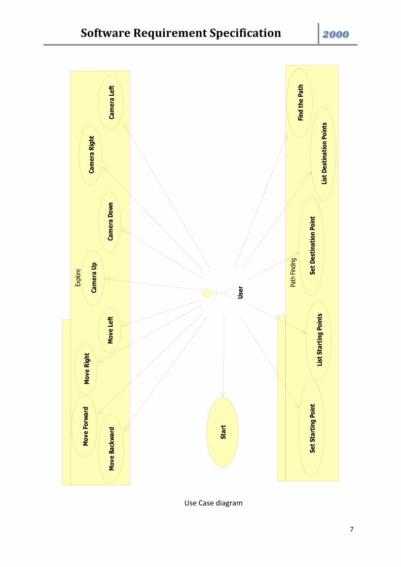
2.2– Product Perspective
Use case diagram of the COW-3D system is revealed in Figure 1. Steps are
gathered in distinct entities, the functions of which are stated in further subsections.
Software Requirement Specification 2000
7
Use Case diagram
Use
rExpl
ore
Mo
ve
Fo
rwa
rd
Mo
ve
Ba
ckw
ard
Mo
ve
Rig
ht
Mo
ve
Le
ft
Ca
me
ra U
p
Ca
me
ra D
ow
n
Ca
me
ra R
igh
t
Ca
me
ra L
eft
Path
Fin
ding
Fin
d t
he
Pa
th
List
De
stin
ati
on
Po
ints
Se
t D
est
ina
tio
n P
oin
t
Sta
rt
Se
t S
tart
ing
Po
int
List
Sta
rtin
g P
oin
ts
Software Requirement Specification 2000
8
2.2.1– Start
Diagram:
Brief Description:
This function becomes active just after touching COW-3D application icon from menu
of the mobile device or when the user enter the web application. After starting user
will be asked to select one of the available modes from either Explore Mode or Path
Finding Mode. This functionality will provide to enter necessity fields.
2.2.2– Explore This interface involves all necessary functionalities as a purpose of getting all relevant
information about exploring from the user.
2.2.2.1– Move Forward
Diagram:
Brief Description:
This function becomes activate when the user press “forward key” button on the
keyboard. This function makes the user move forward.
Start
Move Forward
Software Requirement Specification 2000
9
2.2.2.2– Move Backward Diagram:
Brief Description:
This function becomes activate when the user press “backward key” button on the
keyboard. This function makes the user move backward.
2.2.2.3– Move Right
Diagram:
Brief Description:
This function becomes activate when the user press ‘rightward key’ button on the
keyboard. This function makes the user move right.
Move Backward
Move Right
Software Requirement Specification 2000
10
2.2.2.4– Move Left
Diagram:
Brief Description:
This function becomes activate when the user press “leftward key” button on the
keyboard. This function makes the user move left.
2.2.2.5– Camera Up
Diagram:
Brief Description:
This function becomes activate when the user press ‘Up Arrow Key’ button on the
keyboard. This function makes the view point move up.
Move Left
Camera Up
Software Requirement Specification 2000
11
2.2.2.6– Camera Down
Diagram:
Brief Description:
This function becomes activate when the user press ‘Down Arrow Key’ button on the
keyboard. This function makes the view point move down.
2.2.2.7– Camera Right
Diagram:
Brief Description:
This function becomes activate when the user press ‘Right Arrow Key’ button on the
keyboard. This function makes the view point move right.
Camera Down
Camera Right
Software Requirement Specification 2000
12
2.2.2.8– Camera Left
Diagram:
Brief Description:
This function becomes activate when the user press ‘Left Arrow Key’ button on the
keyboard. This function makes the view point move left.
2.2.3– Path Finding
This interface involves all necessary functionalities as a purpose of getting all relevant
information about shortest path finding from the user.
Camera Left
Software Requirement Specification 2000
13
2.2.3.1– Set Starting Point
Diagram:
Brief Description:
This function becomes activate when the user press ‘Set Start Point’ field on the
screen. User can set the start point directly from here.
2.2.3.2– List Starting Points
Diagram:
Brief Description:
This function becomes activate when the user press ‘Select From Starting Point” field
on the screen. User can see the all starting points.
Set Starting Point
List Starting Points
Software Requirement Specification 2000
14
2.2.3.3– Set Destination Point
Diagram:
Brief Description:
This function becomes activate when the user press ‘Set Destination Point’ field on
the screen. User can set the destination point directly from here.
2.2.3.4– List Destination Poins
Diagram:
Brief Description:
This function becomes activate when the user press ‘Select From Destination Points”
field on the screen. User can see the all destination points.
Set Destination Point
List Destination Points
Software Requirement Specification 2000
15
2.2.3.5 Find the Path
Diagram:
Brief Description:
This function becomes activate when the user press ‘Find the Path’ button on the
screen. User can see the shortest path from starting point to destination point.
3 – Specific Requirements
This section describes the details of software requirement in 3 subsection:
Interface Requirements, Functional Requirements and non-Functional requirements.
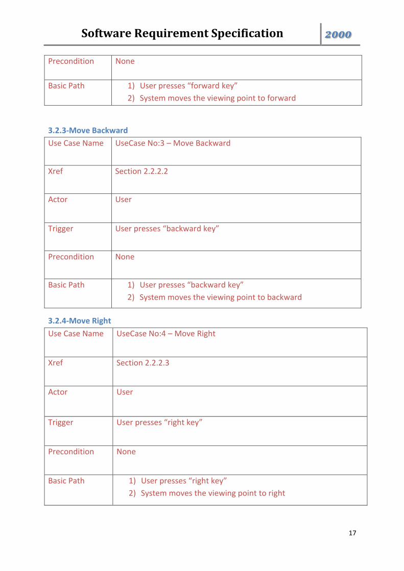
3.1– Interface Requirements
There is only one user and the user interface is shown in the figure which
indicates that user can reach the product either from web browser or Android mobile
application of product.
Find the Path
Software Requirement Specification 2000
16
3.2– Functional Requirements
3.2.1-Start
Use Case Name UseCase No:1 – Start
Xref Section 2.2.1
Actor User
Trigger The user presses “start” button
Precondition None
Basic Path 1) User presses “start” button
2) User select the mode from 2 available modes
3) The system becomes active
3.2.2-Move Forward
Use Case Name UseCase No:2 – Move Forward
Xref Section 2.2.2.1
Actor User
Trigger User presses “forward key”
Software Requirement Specification 2000
17
Precondition None
Basic Path 1) User presses “forward key”
2) System moves the viewing point to forward
3.2.3-Move Backward
Use Case Name UseCase No:3 – Move Backward
Xref Section 2.2.2.2
Actor User
Trigger User presses “backward key”
Precondition None
Basic Path 1) User presses “backward key”
2) System moves the viewing point to backward
3.2.4-Move Right
Use Case Name UseCase No:4 – Move Right
Xref Section 2.2.2.3
Actor User
Trigger User presses “right key”
Precondition None
Basic Path 1) User presses “right key”
2) System moves the viewing point to right
Software Requirement Specification 2000
18
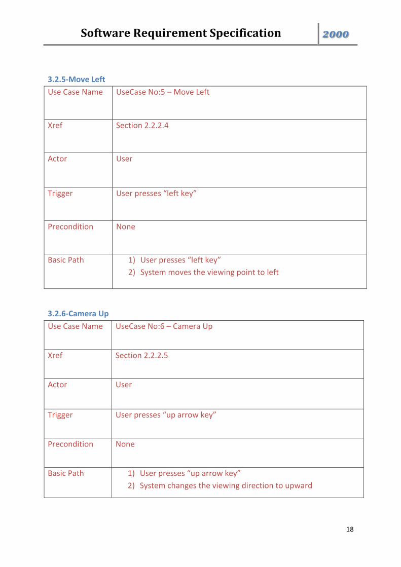
3.2.5-Move Left
Use Case Name UseCase No:5 – Move Left
Xref Section 2.2.2.4
Actor User
Trigger User presses “left key”
Precondition None
Basic Path 1) User presses “left key”
2) System moves the viewing point to left
3.2.6-Camera Up
Use Case Name UseCase No:6 – Camera Up
Xref Section 2.2.2.5
Actor User
Trigger User presses “up arrow key”
Precondition None
Basic Path 1) User presses “up arrow key”
2) System changes the viewing direction to upward
Software Requirement Specification 2000
19
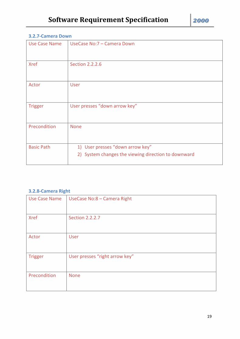
3.2.7-Camera Down
Use Case Name UseCase No:7 – Camera Down
Xref Section 2.2.2.6
Actor User
Trigger User presses “down arrow key”
Precondition None
Basic Path 1) User presses “down arrow key”
2) System changes the viewing direction to downward
3.2.8-Camera Right
Use Case Name UseCase No:8 – Camera Right
Xref Section 2.2.2.7
Actor User
Trigger User presses “right arrow key”
Precondition None
Software Requirement Specification 2000
20
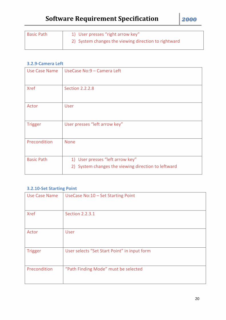
Basic Path 1) User presses “right arrow key”
2) System changes the viewing direction to rightward
3.2.9-Camera Left
Use Case Name UseCase No:9 – Camera Left
Xref Section 2.2.2.8
Actor User
Trigger User presses “left arrow key”
Precondition None
Basic Path 1) User presses “left arrow key”
2) System changes the viewing direction to leftward
3.2.10-Set Starting Point
Use Case Name UseCase No:10 – Set Starting Point
Xref Section 2.2.3.1
Actor User
Trigger User selects “Set Start Point” in input form
Precondition “Path Finding Mode” must be selected
Software Requirement Specification 2000
21
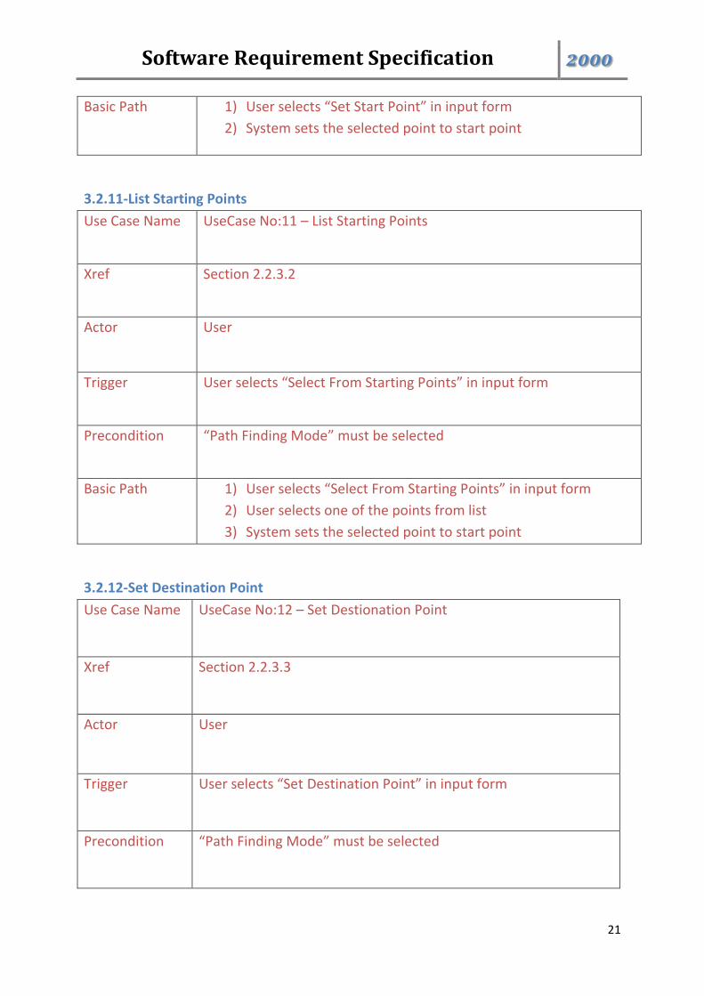
Basic Path 1) User selects “Set Start Point” in input form
2) System sets the selected point to start point
3.2.11-List Starting Points
Use Case Name UseCase No:11 – List Starting Points
Xref Section 2.2.3.2
Actor User
Trigger User selects “Select From Starting Points” in input form
Precondition “Path Finding Mode” must be selected
Basic Path 1) User selects “Select From Starting Points” in input form
2) User selects one of the points from list
3) System sets the selected point to start point
3.2.12-Set Destination Point
Use Case Name UseCase No:12 – Set Destionation Point
Xref Section 2.2.3.3
Actor User
Trigger User selects “Set Destination Point” in input form
Precondition “Path Finding Mode” must be selected
Software Requirement Specification 2000
22
Basic Path 1) User selects “Set Destination Point” in input form
2) System sets the selected point to destination point
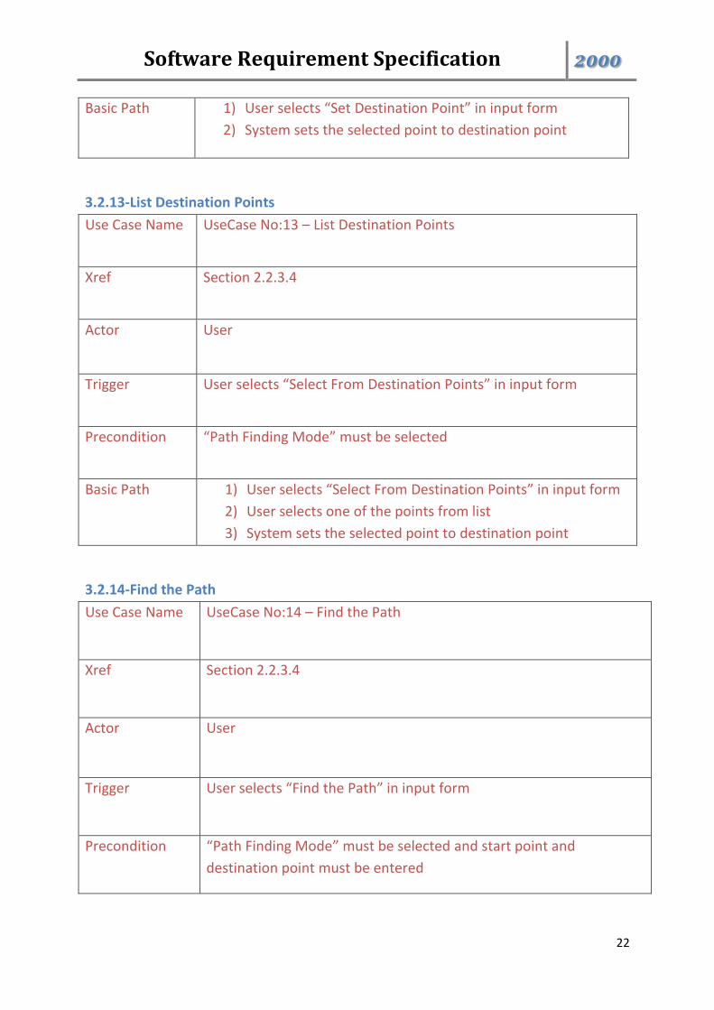
3.2.13-List Destination Points
Use Case Name UseCase No:13 – List Destination Points
Xref Section 2.2.3.4
Actor User
Trigger User selects “Select From Destination Points” in input form
Precondition “Path Finding Mode” must be selected
Basic Path 1) User selects “Select From Destination Points” in input form
2) User selects one of the points from list
3) System sets the selected point to destination point
3.2.14-Find the Path
Use Case Name UseCase No:14 – Find the Path
Xref Section 2.2.3.4
Actor User
Trigger User selects “Find the Path” in input form
Precondition “Path Finding Mode” must be selected and start point and
destination point must be entered
Software Requirement Specification 2000
23
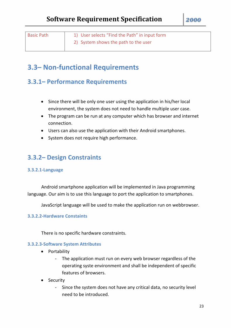
Basic Path 1) User selects “Find the Path” in input form
2) System shows the path to the user
3.3– Non-functional Requirements
3.3.1– Performance Requirements
Since there will be only one user using the application in his/her local
environment, the system does not need to handle multiple user case.
The program can be run at any computer which has browser and internet
connection.
Users can also use the application with their Android smartphones.
System does not require high performance.
3.3.2– Design Constraints
3.3.2.1-Language
Android smartphone application will be implemented in Java programming
language. Our aim is to use this language to port the application to smartphones.
JavaScript language will be used to make the application run on webbrowser.
3.3.2.2-Hardware Constaints
There is no specific hardware constraints.
3.3.2.3-Software System Attributes
Portability
- The application must run on every web browser regardless of the
operating syste environment and shall be independent of specific
features of browsers.
Security
- Since the system does not have any critical data, no security level
need to be introduced.
Software Requirement Specification 2000
24
4 – Data Model and Description
This section describes the basic data models of the system. Each model will be
described with their major attributes.
4.1– Data Description
The data models which are used in this project are:
* Environment
* DataObject
* FirstPersonShooter
4.1.1– Data Objects
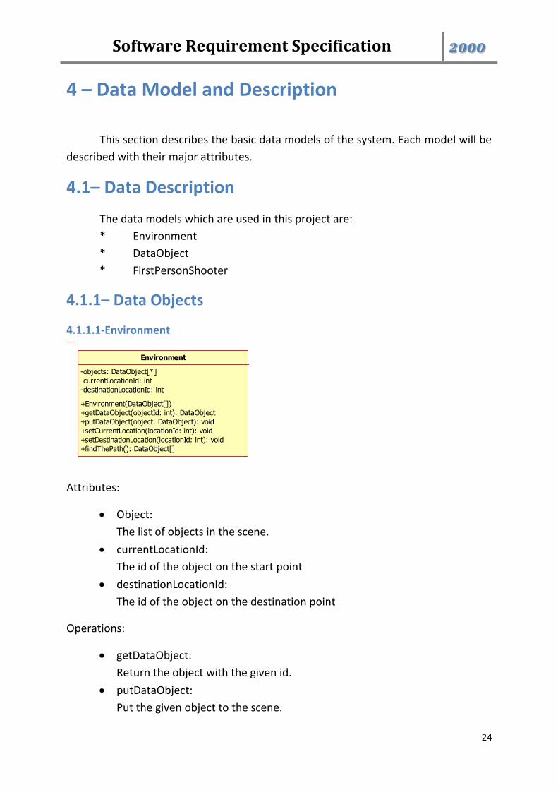
4.1.1.1-Environment
Attributes:
Object:
The list of objects in the scene.
currentLocationId:
The id of the object on the start point
destinationLocationId:
The id of the object on the destination point
Operations:
getDataObject:
Return the object with the given id.
putDataObject:
Put the given object to the scene.
Environment
-objects: DataObject[*]
-currentLocationId: int
-destinationLocationId: int
+Environment(DataObject[])
+getDataObject(objectId: int): DataObject
+putDataObject(object: DataObject): void
+setCurrentLocation(locationId: int): void
+setDestinationLocation(locationId: int): void
+findThePath(): DataObject[]
Software Requirement Specification 2000
25
setCurrentLocation:
Set the current location as the location of the object which has the given id.
setDestinationLocation:
Set the destionation location as the location of the object which has the
given id.
findThePath:
Find a shortest path between the current and destination points and
returns the objects on the calculated path.
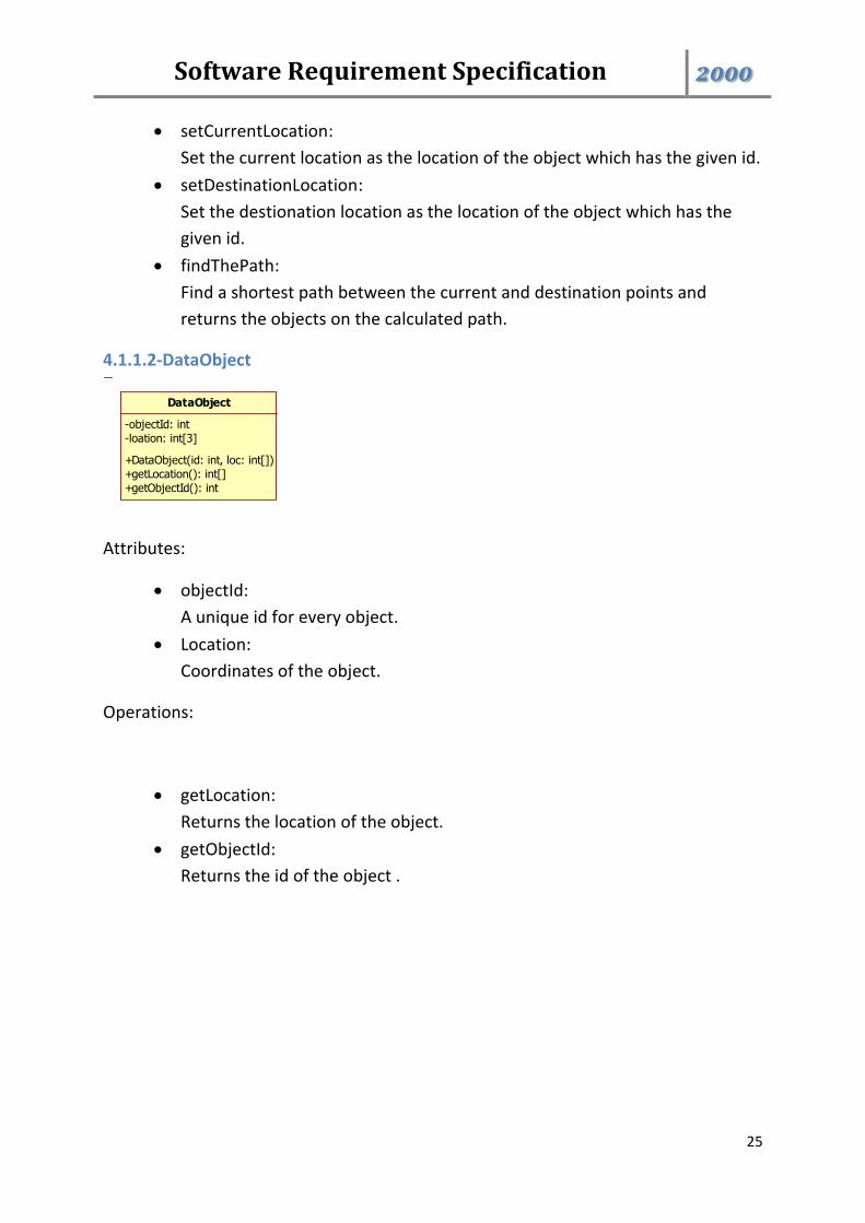
4.1.1.2-DataObject
Attributes:
objectId:
A unique id for every object.
Location:
Coordinates of the object.
Operations:
getLocation:
Returns the location of the object.
getObjectId:
Returns the id of the object .
DataObject
-objectId: int
-loation: int[3]
+DataObject(id: int, loc: int[])
+getLocation(): int[]
+getObjectId(): int
Software Requirement Specification 2000
26
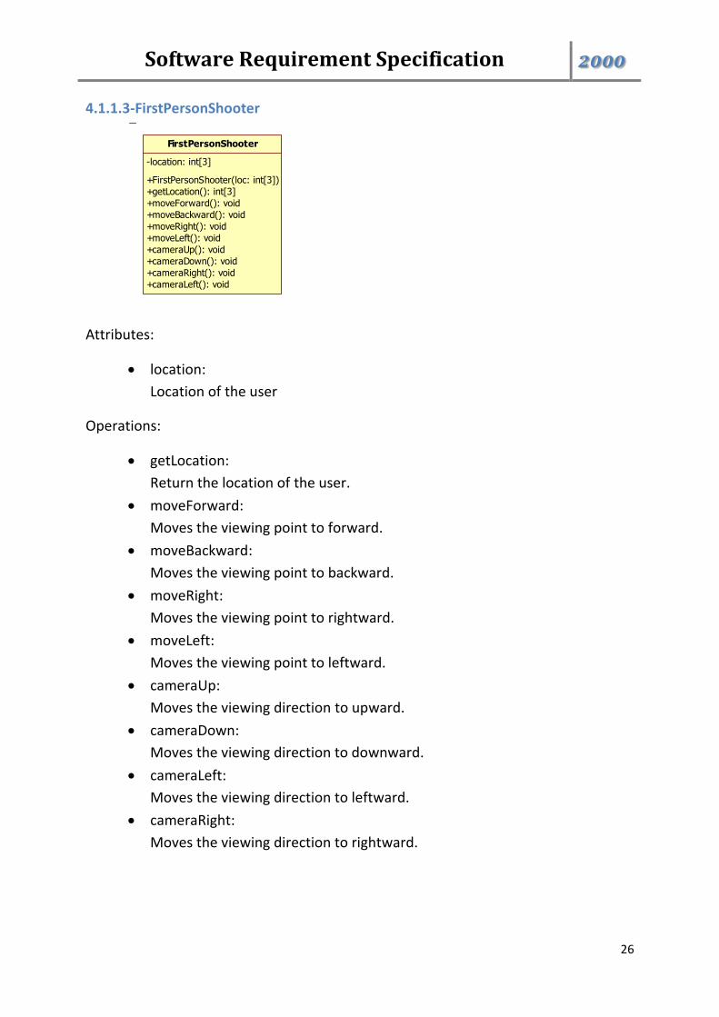
4.1.1.3-FirstPersonShooter
Attributes:
location:
Location of the user
Operations:
getLocation:
Return the location of the user.
moveForward:
Moves the viewing point to forward.
moveBackward:
Moves the viewing point to backward.
moveRight:
Moves the viewing point to rightward.
moveLeft:
Moves the viewing point to leftward.
cameraUp:
Moves the viewing direction to upward.
cameraDown:
Moves the viewing direction to downward.
cameraLeft:
Moves the viewing direction to leftward.
cameraRight:
Moves the viewing direction to rightward.
FirstPersonShooter
-location: int[3]
+FirstPersonShooter(loc: int[3])
+getLocation(): int[3]
+moveForward(): void
+moveBackward(): void
+moveRight(): void
+moveLeft(): void
+cameraUp(): void
+cameraDown(): void
+cameraRight(): void
+cameraLeft(): void
Software Requirement Specification 2000
27
4.1.2– Data Dictionary
The data objects have been explained in detail in section 4.1.1.
5 – Behavioral Model and Decription
This section presents a description of the behavior of the software.
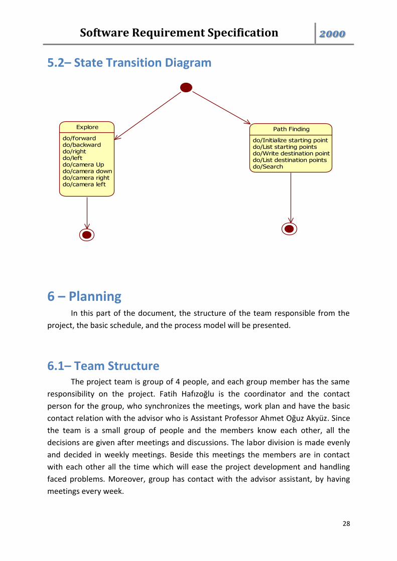
5.1– Description for Software Behavior
When the application starts with a single touch to COW-3D icon or entering
the website of the product, the user will see two options. These are exploring and
path finding options. In the first option, there are some keys which the user use to
move and change camera angle. By using arrow keys, the user can change his/her
view point and thanks to that, the user can explore all his/her around. The user can
use W-S-A-D keys to move forward, backward, right and left respectively.
In the second option, the user can use path finding feature of the product. In
this feature, the user can select starting and destination points or search for
destination point. When the user select start and destination point, application will
show the shortest path according to points. When the user search for destination,
then all possible destination points will be showed and the user will select one of
them. After that application will show the shortest path to the user.
Software Requirement Specification 2000
28
5.2– State Transition Diagram
6 – Planning In this part of the document, the structure of the team responsible from the
project, the basic schedule, and the process model will be presented.
6.1– Team Structure The project team is group of 4 people, and each group member has the same
responsibility on the project. Fatih Hafızoğlu is the coordinator and the contact
person for the group, who synchronizes the meetings, work plan and have the basic
contact relation with the advisor who is Assistant Professor Ahmet Oğuz Akyüz. Since
the team is a small group of people and the members know each other, all the
decisions are given after meetings and discussions. The labor division is made evenly
and decided in weekly meetings. Beside this meetings the members are in contact
with each other all the time which will ease the project development and handling
faced problems. Moreover, group has contact with the advisor assistant, by having
meetings every week.
Explore
do/forwarddo/backwarddo/rightdo/leftdo/camera Updo/camera downdo/camera rightdo/camera left
Path Finding
do/Initialize starting pointdo/List starting pointsdo/Write destination pointdo/List destination pointsdo/Search
Software Requirement Specification 2000
29
All the members of the group has the same level of knowledge about the project.
Therefore, to get the necessary knowledge sooner, the research areas about the
project are divided into 4 different parts and assigned to each member, and the
useful information is shared with the other members. Similar to research, software
development part will be divided into 4 different parts and everyone will develop
COW-3D his own part according to the common decision taken in the meetings.
Therefore, it is not going to be a problem to merge these 4 parts to each other.
During the development period, according to the needs of the project, members will
have some specific tasks decided by the group, but for now mainly our members and
the roles are:
Ali Hopyar – Researcher, Software Developer, Designer, Tester
Fatih Hafızoğlu - Researcher, Software Developer, Coordinator
Volkan Gümüş - Researcher, Software Developer, Designer
Yaşar Halim Kaya - Researcher, Software Developer, Tester
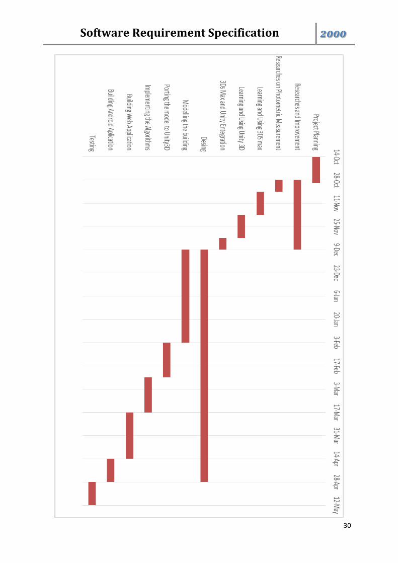
6.2– Estimation
Our aim is to start implementation as soon as possible after finishing
documentation and researches. To start implementation, we decided to start from
begin modelling basic things in 3DS Max and after that port the models we made to
Unity environment. While doing this, each member will also do researches about
making a web and andoid application. The plan is before finishing documentaion,
each member to have enough knowladge to complete entire project.
The basic schedule we decided in our meetings is given below:
Software Requirement Specification 2000
30
Software Requirement Specification 2000
31
6.3– Process Model
We are going to use the incremental process model in the development phase
of the project. The incremental model begins with determining the requirements and
then continues with the development. Depending on the test results, either the
requirements are updated and the process cycle starts from the beginning to satisfy
the new requirements or the system is decided to be deployed.
This model allows us to change the requirements during the process so that
we are able to converge the system into the best state it can be. Although each team
member have been assigned to different tasks, they are expected to contribute the
development of each one.
7 – Conclusion
This report is prepared to show COW-3D project requirement details. Firstly,
the problem intended to be solved is defined, and the details of the solution is
explained. After the basic information about the product, the detailed description of
the requirements are introduced. This includes the user interfaces, product functions,
non-functional requirements, attributes, and design constraints. User and function
relations, data to be processed, and user roles are modeled. After these detailed
explanation about the product, team structure, estimated time schedule, and process
model is stated.
8 – Supporting Information
Table of contents is given below
Software Requirement Specification 2000
32
8.1– Table of Contents
1 – Introduction ........................................................................................................... 1
1.1 – Problem Definition ............................................................................................. 1
1.2– Purpose ................................................................................................................ 1
1.3– Scope.................................................................................................................... 2
1.4– Definitions, Acronyms and Abbreviations ........................................................... 2
1.5– Definitions, Acronyms and Abbreviations ........................................................... 3
1.6– Overview .............................................................................................................. 3
2 – Overall Description ................................................................................................ 4
2.1– Product Perspective ............................................................................................. 4
2.1.1– User Interface ................................................................................................... 5
2.1.2– Hardware Interface .......................................................................................... 6
2.1.3– Software Interface ............................................................................................ 6
2.2– Product Perspective ............................................................................................. 6
2.2.1– Start .................................................................................................................. 8
2.2.2– Explore .............................................................................................................. 8
2.2.2.1– Move Forward ............................................................................................... 8
2.2.2.2– Move Backward ............................................................................................. 9
2.2.2.3– Move Right .................................................................................................... 9
2.2.2.4– Move Left ..................................................................................................... 10
2.2.2.5– Camera Up ................................................................................................... 10
2.2.2.6– Camera Down .............................................................................................. 11
2.2.2.7– Camera Right ............................................................................................... 11
2.2.2.8– Camera Left ................................................................................................. 12
2.2.3– Path Finding .................................................................................................... 12
2.2.3.1– Set Starting Point ......................................................................................... 13
2.2.3.2– List Starting Points ....................................................................................... 13
Software Requirement Specification 2000
33
2.2.3.3– Set Destination Point ................................................................................... 14
2.2.3.4– List Destination Poins .................................................................................. 14
2.2.3.5 Find the Path ................................................................................................. 15
3 – Specific Requirements ......................................................................................... 15
3.1– Interface Requirements ..................................................................................... 15
3.2– Functional Requirements .................................................................................. 16
3.2.1-Start .................................................................................................................. 16
3.2.2-Move Forward .................................................................................................. 16
3.2.3-Move Backward ................................................................................................ 17
3.2.4-Move Right ....................................................................................................... 17
3.2.5-Move Left ......................................................................................................... 18
3.2.6-Camera Up ........................................................................................................ 18
3.2.7-Camera Down ................................................................................................... 19
3.2.8-Camera Right .................................................................................................... 19
3.2.9-Camera Left ...................................................................................................... 20
3.2.10-Set Starting Point ............................................................................................ 20
3.2.11-List Starting Points .......................................................................................... 21
3.2.12-Set Destination Point ..................................................................................... 21
3.2.13-List Destination Points .................................................................................... 22
3.2.14-Find the Path .................................................................................................. 22
3.3– Non-functional Requirements ........................................................................... 23
3.3.1– Performance Requirements ........................................................................... 23
3.3.2– Design Constraints .......................................................................................... 23
3.3.2.1-Language ....................................................................................................... 23
3.3.2.2-Hardware Constaints ..................................................................................... 23
3.3.2.3-Software System Attributes .......................................................................... 23
4 – Data Model and Description ................................................................................ 24
4.1– Data Description ................................................................................................ 24
The data models which are used in this project are: ................................................ 24
Software Requirement Specification 2000
34
4.1.1– Data Objects ................................................................................................... 24
4.1.1.1-Environment .................................................................................................. 24
4.1.1.2-DataObject .................................................................................................... 25
4.1.1.3-FirstPersonShooter ........................................................................................ 26
4.1.2– Data Dictionary ............................................................................................... 27
5 – Behavioral Model and Decription ........................................................................ 27
5.1– Description for Software Behavior .................................................................... 27
5.2– State Transition Diagram ................................................................................... 28
6 – Planning ............................................................................................................... 28
6.1– Team Structure .................................................................................................. 28
6.2– Estimation .......................................................................................................... 29
6.3– Process Model ................................................................................................... 31
7 – Conclusion ............................................................................................................ 31
8 – Supporting Information ....................................................................................... 31
8.1– Table of Contents .............................................................................................. 32