software manual dds system bus can for plc - lenzedownload.lenze.com/td/dds__system bus can for...
TRANSCRIPT

L
Global Drive
System bus (CAN)for Lenze PLC devices
Manual

This documentation is valid for the following Lenze PLC devices:
Automation system Type designation As of hardware version As of software version
9300 Servo PLC EVS93XX−xI 2K 2.0
9300 Servo PLC EVS93XX−xT 2K 2.0
Drive PLC EPL10200 Px 2.0
ECSxA ECSxAxxx 1A 6.0
Important note:
The software is supplied to the user as described in this document. Any risks resulting from its quality or use remain the responsibility of theuser. The user must provide all safety measures protecting against possible maloperation.
We do not take any liability for direct or indirect damage, e.g. profit loss, order loss or any loss regarding business.
� 2006 Lenze Drive Systems GmbH
No part of this documentation may be copied or made available to third parties without the explicit written approval of Lenze Drive SystemsGmbH.
All information given in these Operating Instructions has been selected carefully and comply with the hardware and software described. Ne-vertheless, deviations cannot be ruled out. We do not take any responsibility or liability for damages which might possibly occur. Requiredcorrections will be made in the following editions.
All product names mentioned in this documentation are trademarks of the corresponding owners.
Version 2.0 07/2006 − TD31
System bus (CAN) for Lenze PLC devicesContents
iL PLC−Systembus EN 2.0
1 Preface and general information 1−1 . . . . . . . . . . . . . . . . . . . . . . . . . . . . . . . . . . . . . . . . . . .
1.1 About this Manual 1−1 . . . . . . . . . . . . . . . . . . . . . . . . . . . . . . . . . . . . . . . . . . . . . . . . . . . . . . . . . . . . . . . .
1.1.1 Conventions used in this Manual 1−2 . . . . . . . . . . . . . . . . . . . . . . . . . . . . . . . . . . . . . . . . . . . . . .
1.1.2 Structure of the description 1−3 . . . . . . . . . . . . . . . . . . . . . . . . . . . . . . . . . . . . . . . . . . . . . . . . . .
1.1.3 Pictographs used in this Manual 1−4 . . . . . . . . . . . . . . . . . . . . . . . . . . . . . . . . . . . . . . . . . . . . . . .
1.1.4 Terminology used 1−4 . . . . . . . . . . . . . . . . . . . . . . . . . . . . . . . . . . . . . . . . . . . . . . . . . . . . . . . . .
2 General information on the system bus (CAN) 2−1 . . . . . . . . . . . . . . . . . . . . . . . . . . . . . . . .
2.1 Introduction 2−1 . . . . . . . . . . . . . . . . . . . . . . . . . . . . . . . . . . . . . . . . . . . . . . . . . . . . . . . . . . . . . . . . . . . . .
2.2 Interfaces of the Lenze PLCs for system bus connection 2−2 . . . . . . . . . . . . . . . . . . . . . . . . . . . . . . . . . . . .
2.3 Identification of the nodes 2−3 . . . . . . . . . . . . . . . . . . . . . . . . . . . . . . . . . . . . . . . . . . . . . . . . . . . . . . . . . .
2.4 Structure of the CAN telegram 2−3 . . . . . . . . . . . . . . . . . . . . . . . . . . . . . . . . . . . . . . . . . . . . . . . . . . . . . . .
2.4.1 Identifier 2−3 . . . . . . . . . . . . . . . . . . . . . . . . . . . . . . . . . . . . . . . . . . . . . . . . . . . . . . . . . . . . . . . .
2.4.2 User data 2−5 . . . . . . . . . . . . . . . . . . . . . . . . . . . . . . . . . . . . . . . . . . . . . . . . . . . . . . . . . . . . . . .
2.5 Network management (NMT) 2−6 . . . . . . . . . . . . . . . . . . . . . . . . . . . . . . . . . . . . . . . . . . . . . . . . . . . . . . . .
2.6 Transmission of process data 2−7 . . . . . . . . . . . . . . . . . . . . . . . . . . . . . . . . . . . . . . . . . . . . . . . . . . . . . . . .
2.6.1 Process data channels 2−7 . . . . . . . . . . . . . . . . . . . . . . . . . . . . . . . . . . . . . . . . . . . . . . . . . . . . . .
2.6.2 Sync telegram for cyclic process data 2−9 . . . . . . . . . . . . . . . . . . . . . . . . . . . . . . . . . . . . . . . . . .
2.6.3 Process data telegram 2−10 . . . . . . . . . . . . . . . . . . . . . . . . . . . . . . . . . . . . . . . . . . . . . . . . . . . . . .
2.7 Transmitting parameter data 2−11 . . . . . . . . . . . . . . . . . . . . . . . . . . . . . . . . . . . . . . . . . . . . . . . . . . . . . . . . .
2.7.1 Parameter data telegram 2−11 . . . . . . . . . . . . . . . . . . . . . . . . . . . . . . . . . . . . . . . . . . . . . . . . . . . .
2.7.2 Writing parameters (example) 2−15 . . . . . . . . . . . . . . . . . . . . . . . . . . . . . . . . . . . . . . . . . . . . . . . .
2.7.3 Reading a parameter (example) 2−17 . . . . . . . . . . . . . . . . . . . . . . . . . . . . . . . . . . . . . . . . . . . . . . .
2.8 Free CAN objects 2−19 . . . . . . . . . . . . . . . . . . . . . . . . . . . . . . . . . . . . . . . . . . . . . . . . . . . . . . . . . . . . . . . . .
2.9 Application recommendations for the different CAN objects 2−20 . . . . . . . . . . . . . . . . . . . . . . . . . . . . . . . . . .
2.10 Monitoring mechanisms 2−21 . . . . . . . . . . . . . . . . . . . . . . . . . . . . . . . . . . . . . . . . . . . . . . . . . . . . . . . . . . . .
2.10.1 "Heartbeat" 2−21 . . . . . . . . . . . . . . . . . . . . . . . . . . . . . . . . . . . . . . . . . . . . . . . . . . . . . . . . . . . . . .
2.10.2 "Node Guarding" 2−22 . . . . . . . . . . . . . . . . . . . . . . . . . . . . . . . . . . . . . . . . . . . . . . . . . . . . . . . . . .
3 Configuration (system bus − CAN interface) 3−1 . . . . . . . . . . . . . . . . . . . . . . . . . . . . . . . . . .
3.1 CAN baud rate 3−1 . . . . . . . . . . . . . . . . . . . . . . . . . . . . . . . . . . . . . . . . . . . . . . . . . . . . . . . . . . . . . . . . . . .
3.2 CAN boot−up 3−2 . . . . . . . . . . . . . . . . . . . . . . . . . . . . . . . . . . . . . . . . . . . . . . . . . . . . . . . . . . . . . . . . . . . .
3.3 Node address (node ID) 3−3 . . . . . . . . . . . . . . . . . . . . . . . . . . . . . . . . . . . . . . . . . . . . . . . . . . . . . . . . . . . .
3.4 Identifiers of the process data objects 3−4 . . . . . . . . . . . . . . . . . . . . . . . . . . . . . . . . . . . . . . . . . . . . . . . . . .
3.4.1 Allocation of individual identifiers 3−4 . . . . . . . . . . . . . . . . . . . . . . . . . . . . . . . . . . . . . . . . . . . . . .
3.4.2 Display of the identifier set 3−5 . . . . . . . . . . . . . . . . . . . . . . . . . . . . . . . . . . . . . . . . . . . . . . . . . .
3.5 Cycle time (CAN2_OUT/CAN3_OUT) 3−6 . . . . . . . . . . . . . . . . . . . . . . . . . . . . . . . . . . . . . . . . . . . . . . . . . . . .
3.6 Delay time (CAN2_OUT/CAN3_OUT) 3−6 . . . . . . . . . . . . . . . . . . . . . . . . . . . . . . . . . . . . . . . . . . . . . . . . . . .
3.7 Synchronisation 3−7 . . . . . . . . . . . . . . . . . . . . . . . . . . . . . . . . . . . . . . . . . . . . . . . . . . . . . . . . . . . . . . . . . .
3.7.1 CAN sync response 3−7 . . . . . . . . . . . . . . . . . . . . . . . . . . . . . . . . . . . . . . . . . . . . . . . . . . . . . . . .
3.7.2 CAN sync identifiers 3−7 . . . . . . . . . . . . . . . . . . . . . . . . . . . . . . . . . . . . . . . . . . . . . . . . . . . . . . .
3.7.3 CAN sync Tx transmission cycle 3−7 . . . . . . . . . . . . . . . . . . . . . . . . . . . . . . . . . . . . . . . . . . . . . . .
3.8 Reset node 3−8 . . . . . . . . . . . . . . . . . . . . . . . . . . . . . . . . . . . . . . . . . . . . . . . . . . . . . . . . . . . . . . . . . . . . .
3.9 System bus management 3−8 . . . . . . . . . . . . . . . . . . . . . . . . . . . . . . . . . . . . . . . . . . . . . . . . . . . . . . . . . . .
3.10 Mapping indexes to codes 3−8 . . . . . . . . . . . . . . . . . . . . . . . . . . . . . . . . . . . . . . . . . . . . . . . . . . . . . . . . . .
3.10.1 Functional principle considering as example 3−9 . . . . . . . . . . . . . . . . . . . . . . . . . . . . . . . . . . . . . .
System bus (CAN) for Lenze PLC devicesContents
ii LPLC−Systembus EN 2.0
3.11 Remote parameterisation (gateway function) 3−10 . . . . . . . . . . . . . . . . . . . . . . . . . . . . . . . . . . . . . . . . . . . . .
3.12 Monitoring processes 3−11 . . . . . . . . . . . . . . . . . . . . . . . . . . . . . . . . . . . . . . . . . . . . . . . . . . . . . . . . . . . . . .
3.12.1 Time monitoring for CAN1_IN ... CAN3_IN 3−11 . . . . . . . . . . . . . . . . . . . . . . . . . . . . . . . . . . . . . . . .
3.12.2 Bus−off 3−11 . . . . . . . . . . . . . . . . . . . . . . . . . . . . . . . . . . . . . . . . . . . . . . . . . . . . . . . . . . . . . . . . .
3.12.3 Time−out when remote parameterisation is activated 3−12 . . . . . . . . . . . . . . . . . . . . . . . . . . . . . . .
3.12.4 Response in the case of system bus fault messages 3−12 . . . . . . . . . . . . . . . . . . . . . . . . . . . . . . . .
3.13 Diagnostics 3−13 . . . . . . . . . . . . . . . . . . . . . . . . . . . . . . . . . . . . . . . . . . . . . . . . . . . . . . . . . . . . . . . . . . . . .
3.13.1 Operating status of the CAN interface 3−13 . . . . . . . . . . . . . . . . . . . . . . . . . . . . . . . . . . . . . . . . . . .
3.13.2 Telegram counter 3−14 . . . . . . . . . . . . . . . . . . . . . . . . . . . . . . . . . . . . . . . . . . . . . . . . . . . . . . . . .
3.13.3 Bus load by the PLC 3−15 . . . . . . . . . . . . . . . . . . . . . . . . . . . . . . . . . . . . . . . . . . . . . . . . . . . . . . .
4 Configuration (AIF interface) 4−1 . . . . . . . . . . . . . . . . . . . . . . . . . . . . . . . . . . . . . . . . . . . . . .
4.1 CAN baud rate 4−1 . . . . . . . . . . . . . . . . . . . . . . . . . . . . . . . . . . . . . . . . . . . . . . . . . . . . . . . . . . . . . . . . . . .
4.2 CAN boot−up 4−2 . . . . . . . . . . . . . . . . . . . . . . . . . . . . . . . . . . . . . . . . . . . . . . . . . . . . . . . . . . . . . . . . . . . .
4.3 Node address (node ID) 4−3 . . . . . . . . . . . . . . . . . . . . . . . . . . . . . . . . . . . . . . . . . . . . . . . . . . . . . . . . . . . .
4.4 Identifiers of the process data objects 4−4 . . . . . . . . . . . . . . . . . . . . . . . . . . . . . . . . . . . . . . . . . . . . . . . . . .
4.4.1 Allocation of individual identifiers 4−4 . . . . . . . . . . . . . . . . . . . . . . . . . . . . . . . . . . . . . . . . . . . . . .
4.4.2 Display of the identifier set 4−5 . . . . . . . . . . . . . . . . . . . . . . . . . . . . . . . . . . . . . . . . . . . . . . . . . .
4.5 Cycle time (XCAN1_OUT ... XCAN3_OUT) 4−6 . . . . . . . . . . . . . . . . . . . . . . . . . . . . . . . . . . . . . . . . . . . . . . . .
4.6 Synchronisation 4−7 . . . . . . . . . . . . . . . . . . . . . . . . . . . . . . . . . . . . . . . . . . . . . . . . . . . . . . . . . . . . . . . . . .
4.6.1 XCAN sync response 4−7 . . . . . . . . . . . . . . . . . . . . . . . . . . . . . . . . . . . . . . . . . . . . . . . . . . . . . . .
4.6.2 XCAN sync identifier 4−7 . . . . . . . . . . . . . . . . . . . . . . . . . . . . . . . . . . . . . . . . . . . . . . . . . . . . . . .
4.6.3 XCAN sync Tx transmission cycle 4−7 . . . . . . . . . . . . . . . . . . . . . . . . . . . . . . . . . . . . . . . . . . . . . .
4.7 Reset node 4−8 . . . . . . . . . . . . . . . . . . . . . . . . . . . . . . . . . . . . . . . . . . . . . . . . . . . . . . . . . . . . . . . . . . . . .
4.8 Monitoring processes 4−8 . . . . . . . . . . . . . . . . . . . . . . . . . . . . . . . . . . . . . . . . . . . . . . . . . . . . . . . . . . . . . .
4.8.1 Time monitoring for XCAN1_IN ... XCAN3_IN 4−8 . . . . . . . . . . . . . . . . . . . . . . . . . . . . . . . . . . . . . .
4.8.2 Bus off 4−9 . . . . . . . . . . . . . . . . . . . . . . . . . . . . . . . . . . . . . . . . . . . . . . . . . . . . . . . . . . . . . . . . .
4.8.3 Response for system bus fault messages 4−9 . . . . . . . . . . . . . . . . . . . . . . . . . . . . . . . . . . . . . . . .
4.9 Diagnostics 4−10 . . . . . . . . . . . . . . . . . . . . . . . . . . . . . . . . . . . . . . . . . . . . . . . . . . . . . . . . . . . . . . . . . . . . .
4.9.1 Automation interface (AIF) operating status 4−10 . . . . . . . . . . . . . . . . . . . . . . . . . . . . . . . . . . . . . .
5 Configuration (FIF interface) 5−1 . . . . . . . . . . . . . . . . . . . . . . . . . . . . . . . . . . . . . . . . . . . . . .
5.1 CAN baud rate 5−1 . . . . . . . . . . . . . . . . . . . . . . . . . . . . . . . . . . . . . . . . . . . . . . . . . . . . . . . . . . . . . . . . . . .
5.2 CAN boot−up 5−2 . . . . . . . . . . . . . . . . . . . . . . . . . . . . . . . . . . . . . . . . . . . . . . . . . . . . . . . . . . . . . . . . . . . .
5.3 Node address (node ID) 5−3 . . . . . . . . . . . . . . . . . . . . . . . . . . . . . . . . . . . . . . . . . . . . . . . . . . . . . . . . . . . .
5.4 Identifiers of the process data objects 5−4 . . . . . . . . . . . . . . . . . . . . . . . . . . . . . . . . . . . . . . . . . . . . . . . . . .
5.4.1 Allocation of individual identifiers 5−4 . . . . . . . . . . . . . . . . . . . . . . . . . . . . . . . . . . . . . . . . . . . . . .
5.4.2 Display of the identifiers set 5−5 . . . . . . . . . . . . . . . . . . . . . . . . . . . . . . . . . . . . . . . . . . . . . . . . . .
5.5 Cycle time (FIF_CAN2_OUT/FIF_CAN3_OUT) 5−6 . . . . . . . . . . . . . . . . . . . . . . . . . . . . . . . . . . . . . . . . . . . . .
5.6 Delay time (FIF_CAN2_OUT/FIF_CAN3_OUT) 5−6 . . . . . . . . . . . . . . . . . . . . . . . . . . . . . . . . . . . . . . . . . . . . .
5.7 Synchronisation 5−7 . . . . . . . . . . . . . . . . . . . . . . . . . . . . . . . . . . . . . . . . . . . . . . . . . . . . . . . . . . . . . . . . . .
5.7.1 FIF−CAN sync response 5−7 . . . . . . . . . . . . . . . . . . . . . . . . . . . . . . . . . . . . . . . . . . . . . . . . . . . . .
5.7.2 FIF−CAN sync identifier 5−7 . . . . . . . . . . . . . . . . . . . . . . . . . . . . . . . . . . . . . . . . . . . . . . . . . . . . .
5.7.3 FIF−CAN sync Tx transmission cycle 5−7 . . . . . . . . . . . . . . . . . . . . . . . . . . . . . . . . . . . . . . . . . . . .
5.8 Reset node 5−8 . . . . . . . . . . . . . . . . . . . . . . . . . . . . . . . . . . . . . . . . . . . . . . . . . . . . . . . . . . . . . . . . . . . . .

System bus (CAN) for Lenze PLC devicesContents
iiiL PLC−Systembus EN 2.0
5.9 System bus management 5−8 . . . . . . . . . . . . . . . . . . . . . . . . . . . . . . . . . . . . . . . . . . . . . . . . . . . . . . . . . . .
5.10 Monitoring processes 5−9 . . . . . . . . . . . . . . . . . . . . . . . . . . . . . . . . . . . . . . . . . . . . . . . . . . . . . . . . . . . . . .
5.10.1 Time monitoring for FIF−CAN1_IN ... FIF−CAN3_IN 5−9 . . . . . . . . . . . . . . . . . . . . . . . . . . . . . . . . . .
5.10.2 Bus−off 5−9 . . . . . . . . . . . . . . . . . . . . . . . . . . . . . . . . . . . . . . . . . . . . . . . . . . . . . . . . . . . . . . . . .
5.10.3 Response in the case of system bus fault messages 5−10 . . . . . . . . . . . . . . . . . . . . . . . . . . . . . . . .
5.11 Diagnostics 5−11 . . . . . . . . . . . . . . . . . . . . . . . . . . . . . . . . . . . . . . . . . . . . . . . . . . . . . . . . . . . . . . . . . . . . .
5.11.1 Function interface (FIF) operating status 5−11 . . . . . . . . . . . . . . . . . . . . . . . . . . . . . . . . . . . . . . . . .
5.11.2 Telegram counter 5−12 . . . . . . . . . . . . . . . . . . . . . . . . . . . . . . . . . . . . . . . . . . . . . . . . . . . . . . . . .
5.11.3 Bus load by FIF−CAN 5−13 . . . . . . . . . . . . . . . . . . . . . . . . . . . . . . . . . . . . . . . . . . . . . . . . . . . . . . .
6 Configuration (CAN−AUX system bus interface) 6−1 . . . . . . . . . . . . . . . . . . . . . . . . . . . . . . .
6.1 CAN baud rate 6−1 . . . . . . . . . . . . . . . . . . . . . . . . . . . . . . . . . . . . . . . . . . . . . . . . . . . . . . . . . . . . . . . . . . .
6.2 CAN boot−up 6−2 . . . . . . . . . . . . . . . . . . . . . . . . . . . . . . . . . . . . . . . . . . . . . . . . . . . . . . . . . . . . . . . . . . . .
6.3 Node address (Node ID) 6−3 . . . . . . . . . . . . . . . . . . . . . . . . . . . . . . . . . . . . . . . . . . . . . . . . . . . . . . . . . . . .
6.4 Identifiers of the process data objects 6−4 . . . . . . . . . . . . . . . . . . . . . . . . . . . . . . . . . . . . . . . . . . . . . . . . . .
6.4.1 Allocation of individual identifiers 6−4 . . . . . . . . . . . . . . . . . . . . . . . . . . . . . . . . . . . . . . . . . . . . . .
6.4.2 Display of the identifiers set 6−5 . . . . . . . . . . . . . . . . . . . . . . . . . . . . . . . . . . . . . . . . . . . . . . . . . .
6.5 Cycle time (CANaux2_OUT/CANaux3_OUT) 6−6 . . . . . . . . . . . . . . . . . . . . . . . . . . . . . . . . . . . . . . . . . . . . . .
6.6 Delay time (CANaux2_OUT/CANaux3_OUT) 6−6 . . . . . . . . . . . . . . . . . . . . . . . . . . . . . . . . . . . . . . . . . . . . . .
6.7 Synchronisation 6−7 . . . . . . . . . . . . . . . . . . . . . . . . . . . . . . . . . . . . . . . . . . . . . . . . . . . . . . . . . . . . . . . . . .
6.7.1 CANaux sync response 6−7 . . . . . . . . . . . . . . . . . . . . . . . . . . . . . . . . . . . . . . . . . . . . . . . . . . . . .
6.7.2 CANaux sync identifiers 6−7 . . . . . . . . . . . . . . . . . . . . . . . . . . . . . . . . . . . . . . . . . . . . . . . . . . . . .
6.7.3 CANaux sync Tx transmission cycle 6−7 . . . . . . . . . . . . . . . . . . . . . . . . . . . . . . . . . . . . . . . . . . . .
6.8 Reset node 6−8 . . . . . . . . . . . . . . . . . . . . . . . . . . . . . . . . . . . . . . . . . . . . . . . . . . . . . . . . . . . . . . . . . . . . .
6.9 System bus management 6−8 . . . . . . . . . . . . . . . . . . . . . . . . . . . . . . . . . . . . . . . . . . . . . . . . . . . . . . . . . . .
6.10 Monitoring processes 6−9 . . . . . . . . . . . . . . . . . . . . . . . . . . . . . . . . . . . . . . . . . . . . . . . . . . . . . . . . . . . . . .
6.10.1 Time monitoring for CANaux1_IN ... CANaux3_IN 6−9 . . . . . . . . . . . . . . . . . . . . . . . . . . . . . . . . . .
6.10.2 Bus−off 6−9 . . . . . . . . . . . . . . . . . . . . . . . . . . . . . . . . . . . . . . . . . . . . . . . . . . . . . . . . . . . . . . . . .
6.10.3 Response in the case of system bus fault messages 6−10 . . . . . . . . . . . . . . . . . . . . . . . . . . . . . . . .
6.11 Diagnostics 6−11 . . . . . . . . . . . . . . . . . . . . . . . . . . . . . . . . . . . . . . . . . . . . . . . . . . . . . . . . . . . . . . . . . . . . .
6.11.1 Operating status of the CAN−AUX interface 6−11 . . . . . . . . . . . . . . . . . . . . . . . . . . . . . . . . . . . . . . .
6.11.2 Telegram counter 6−12 . . . . . . . . . . . . . . . . . . . . . . . . . . . . . . . . . . . . . . . . . . . . . . . . . . . . . . . . .
6.11.3 Bus load by CAN−AUX 6−13 . . . . . . . . . . . . . . . . . . . . . . . . . . . . . . . . . . . . . . . . . . . . . . . . . . . . . .
7 CAN system blocks 7−1 . . . . . . . . . . . . . . . . . . . . . . . . . . . . . . . . . . . . . . . . . . . . . . . . . . . . .
7.1 CAN1_IO (node number: 31) − 9300 Servo PLC 7−1 . . . . . . . . . . . . . . . . . . . . . . . . . . . . . . . . . . . . . . . . . . .
7.1.1 Inputs_CAN1 7−2 . . . . . . . . . . . . . . . . . . . . . . . . . . . . . . . . . . . . . . . . . . . . . . . . . . . . . . . . . . . . .
7.1.2 Outputs_CAN1 7−2 . . . . . . . . . . . . . . . . . . . . . . . . . . . . . . . . . . . . . . . . . . . . . . . . . . . . . . . . . . . .
7.1.3 Process data telegram 7−3 . . . . . . . . . . . . . . . . . . . . . . . . . . . . . . . . . . . . . . . . . . . . . . . . . . . . . .
7.1.4 Assignment of the user data to variables 7−3 . . . . . . . . . . . . . . . . . . . . . . . . . . . . . . . . . . . . . . . .
7.1.5 Transferring status and control information of the device control 7−5 . . . . . . . . . . . . . . . . . . . . . . .
7.2 CAN1_IO (node number: 31) − Drive PLC 7−6 . . . . . . . . . . . . . . . . . . . . . . . . . . . . . . . . . . . . . . . . . . . . . . . .
7.2.1 Inputs_CAN1 7−7 . . . . . . . . . . . . . . . . . . . . . . . . . . . . . . . . . . . . . . . . . . . . . . . . . . . . . . . . . . . . .
7.2.2 Outputs_CAN1 7−7 . . . . . . . . . . . . . . . . . . . . . . . . . . . . . . . . . . . . . . . . . . . . . . . . . . . . . . . . . . . .
7.2.3 Process data telegram 7−8 . . . . . . . . . . . . . . . . . . . . . . . . . . . . . . . . . . . . . . . . . . . . . . . . . . . . . .
7.2.4 Assignment of the user data to variables 7−8 . . . . . . . . . . . . . . . . . . . . . . . . . . . . . . . . . . . . . . . .
System bus (CAN) for Lenze PLC devicesContents
iv LPLC−Systembus EN 2.0
7.3 CAN1_IO (node number: 31) − ECSxA 7−10 . . . . . . . . . . . . . . . . . . . . . . . . . . . . . . . . . . . . . . . . . . . . . . . . . .
7.3.1 Inputs_CAN1 7−11 . . . . . . . . . . . . . . . . . . . . . . . . . . . . . . . . . . . . . . . . . . . . . . . . . . . . . . . . . . . . .
7.3.2 Outputs_CAN1 7−11 . . . . . . . . . . . . . . . . . . . . . . . . . . . . . . . . . . . . . . . . . . . . . . . . . . . . . . . . . . . .
7.3.3 Process data telegram 7−12 . . . . . . . . . . . . . . . . . . . . . . . . . . . . . . . . . . . . . . . . . . . . . . . . . . . . . .
7.3.4 Assignment of the user data to variables 7−12 . . . . . . . . . . . . . . . . . . . . . . . . . . . . . . . . . . . . . . . .
7.4 CAN2_IO (node number: 32) 7−14 . . . . . . . . . . . . . . . . . . . . . . . . . . . . . . . . . . . . . . . . . . . . . . . . . . . . . . . . .
7.4.1 Inputs_CAN2 7−15 . . . . . . . . . . . . . . . . . . . . . . . . . . . . . . . . . . . . . . . . . . . . . . . . . . . . . . . . . . . . .
7.4.2 Outputs_CAN2 7−15 . . . . . . . . . . . . . . . . . . . . . . . . . . . . . . . . . . . . . . . . . . . . . . . . . . . . . . . . . . . .
7.4.3 Process data telegram 7−15 . . . . . . . . . . . . . . . . . . . . . . . . . . . . . . . . . . . . . . . . . . . . . . . . . . . . . .
7.4.4 Assignment of the user data to variables 7−16 . . . . . . . . . . . . . . . . . . . . . . . . . . . . . . . . . . . . . . . .
7.5 CAN3_IO (node number: 33) 7−17 . . . . . . . . . . . . . . . . . . . . . . . . . . . . . . . . . . . . . . . . . . . . . . . . . . . . . . . . .
7.5.1 Inputs_CAN3 7−18 . . . . . . . . . . . . . . . . . . . . . . . . . . . . . . . . . . . . . . . . . . . . . . . . . . . . . . . . . . . . .
7.5.2 Outputs_CAN3 7−18 . . . . . . . . . . . . . . . . . . . . . . . . . . . . . . . . . . . . . . . . . . . . . . . . . . . . . . . . . . . .
7.5.3 Process data telegram 7−18 . . . . . . . . . . . . . . . . . . . . . . . . . . . . . . . . . . . . . . . . . . . . . . . . . . . . . .
7.5.4 Assignment of the user data to variables 7−19 . . . . . . . . . . . . . . . . . . . . . . . . . . . . . . . . . . . . . . . .
7.6 CAN_Management (node number: 101) 7−20 . . . . . . . . . . . . . . . . . . . . . . . . . . . . . . . . . . . . . . . . . . . . . . . . .
7.6.1 Inputs_CAN_Management 7−20 . . . . . . . . . . . . . . . . . . . . . . . . . . . . . . . . . . . . . . . . . . . . . . . . . . .
7.6.2 Outputs_CAN_Management 7−21 . . . . . . . . . . . . . . . . . . . . . . . . . . . . . . . . . . . . . . . . . . . . . . . . . .
7.6.3 Activating a reset node 7−21 . . . . . . . . . . . . . . . . . . . . . . . . . . . . . . . . . . . . . . . . . . . . . . . . . . . . .
7.6.4 Defining the instant of transmission for CAN2_OUT/CAN3_OUT 7−21 . . . . . . . . . . . . . . . . . . . . . . . .
7.6.5 Status messages 7−22 . . . . . . . . . . . . . . . . . . . . . . . . . . . . . . . . . . . . . . . . . . . . . . . . . . . . . . . . . .
7.7 CAN_Synchronization (node number: 102) 7−23 . . . . . . . . . . . . . . . . . . . . . . . . . . . . . . . . . . . . . . . . . . . . . . .
8 FIF−CAN system blocks (only Drive PLC) 8−1 . . . . . . . . . . . . . . . . . . . . . . . . . . . . . . . . . . . . .
8.1 FIF_CAN1_IO (node number: 34) 8−1 . . . . . . . . . . . . . . . . . . . . . . . . . . . . . . . . . . . . . . . . . . . . . . . . . . . . . .
8.1.1 FIF_Inputs_CAN1 8−2 . . . . . . . . . . . . . . . . . . . . . . . . . . . . . . . . . . . . . . . . . . . . . . . . . . . . . . . . . .
8.1.2 FIF_Outputs_CAN1 8−2 . . . . . . . . . . . . . . . . . . . . . . . . . . . . . . . . . . . . . . . . . . . . . . . . . . . . . . . .
8.1.3 Process data telegram 8−3 . . . . . . . . . . . . . . . . . . . . . . . . . . . . . . . . . . . . . . . . . . . . . . . . . . . . . .
8.1.4 Assignment of the user data to variables 8−3 . . . . . . . . . . . . . . . . . . . . . . . . . . . . . . . . . . . . . . . .
8.2 FIF_CAN2_IO (node number: 35) 8−1 . . . . . . . . . . . . . . . . . . . . . . . . . . . . . . . . . . . . . . . . . . . . . . . . . . . . . .
8.2.1 FIF_Inputs_CAN2 8−2 . . . . . . . . . . . . . . . . . . . . . . . . . . . . . . . . . . . . . . . . . . . . . . . . . . . . . . . . . .
8.2.2 FIF_Outputs_CAN2 8−2 . . . . . . . . . . . . . . . . . . . . . . . . . . . . . . . . . . . . . . . . . . . . . . . . . . . . . . . .
8.2.3 Process data telegram 8−2 . . . . . . . . . . . . . . . . . . . . . . . . . . . . . . . . . . . . . . . . . . . . . . . . . . . . . .
8.2.4 Assignment of the user data to variables 8−3 . . . . . . . . . . . . . . . . . . . . . . . . . . . . . . . . . . . . . . . .
8.3 FIF_CAN3_IO (node number: 36) 8−1 . . . . . . . . . . . . . . . . . . . . . . . . . . . . . . . . . . . . . . . . . . . . . . . . . . . . . .
8.3.1 FIF_Inputs_CAN3 8−2 . . . . . . . . . . . . . . . . . . . . . . . . . . . . . . . . . . . . . . . . . . . . . . . . . . . . . . . . . .
8.3.2 FIF_Outputs_CAN3 8−2 . . . . . . . . . . . . . . . . . . . . . . . . . . . . . . . . . . . . . . . . . . . . . . . . . . . . . . . .
8.3.3 Process data telegram 8−2 . . . . . . . . . . . . . . . . . . . . . . . . . . . . . . . . . . . . . . . . . . . . . . . . . . . . . .
8.3.4 Assignment of the user data to variables 8−3 . . . . . . . . . . . . . . . . . . . . . . . . . . . . . . . . . . . . . . . .
8.4 FIF_CAN_Management (node number: 111) 8−4 . . . . . . . . . . . . . . . . . . . . . . . . . . . . . . . . . . . . . . . . . . . . .
8.4.1 FIF_Inputs_CAN_Management 8−4 . . . . . . . . . . . . . . . . . . . . . . . . . . . . . . . . . . . . . . . . . . . . . . . .
8.4.2 FIF_Outputs_CAN_Management 8−5 . . . . . . . . . . . . . . . . . . . . . . . . . . . . . . . . . . . . . . . . . . . . . . .
8.4.3 Activating a reset node 8−5 . . . . . . . . . . . . . . . . . . . . . . . . . . . . . . . . . . . . . . . . . . . . . . . . . . . . .
8.4.4 Defining the instant of transmission for FIF−CAN2_OUT/FIF−CAN3_OUT 8−5 . . . . . . . . . . . . . . . . . .
8.4.5 Status messages 8−6 . . . . . . . . . . . . . . . . . . . . . . . . . . . . . . . . . . . . . . . . . . . . . . . . . . . . . . . . . .

System bus (CAN) for Lenze PLC devicesContents
vL PLC−Systembus EN 2.0
9 CAN−AUX system blocks (only ECSxA) 9−1 . . . . . . . . . . . . . . . . . . . . . . . . . . . . . . . . . . . . . .
9.1 CANaux1_IO (node number: 34) 9−1 . . . . . . . . . . . . . . . . . . . . . . . . . . . . . . . . . . . . . . . . . . . . . . . . . . . . . .
9.1.1 Inputs_CANaux1 9−2 . . . . . . . . . . . . . . . . . . . . . . . . . . . . . . . . . . . . . . . . . . . . . . . . . . . . . . . . . .
9.1.2 Outputs_CANaux1 9−2 . . . . . . . . . . . . . . . . . . . . . . . . . . . . . . . . . . . . . . . . . . . . . . . . . . . . . . . . .
9.1.3 Process data telegram 9−3 . . . . . . . . . . . . . . . . . . . . . . . . . . . . . . . . . . . . . . . . . . . . . . . . . . . . . .
9.1.4 Assignment of the user data to variables 9−3 . . . . . . . . . . . . . . . . . . . . . . . . . . . . . . . . . . . . . . . .
9.2 CANaux2_IO (node number: 35) 9−1 . . . . . . . . . . . . . . . . . . . . . . . . . . . . . . . . . . . . . . . . . . . . . . . . . . . . . .
9.2.1 Inputs_CANaux2 9−2 . . . . . . . . . . . . . . . . . . . . . . . . . . . . . . . . . . . . . . . . . . . . . . . . . . . . . . . . . .
9.2.2 Outputs_CANaux2 9−2 . . . . . . . . . . . . . . . . . . . . . . . . . . . . . . . . . . . . . . . . . . . . . . . . . . . . . . . . .
9.2.3 Process data telegram 9−2 . . . . . . . . . . . . . . . . . . . . . . . . . . . . . . . . . . . . . . . . . . . . . . . . . . . . . .
9.2.4 Assignment of the user data to variables 9−3 . . . . . . . . . . . . . . . . . . . . . . . . . . . . . . . . . . . . . . . .
9.3 CANaux3_IO (node number: 36) 9−1 . . . . . . . . . . . . . . . . . . . . . . . . . . . . . . . . . . . . . . . . . . . . . . . . . . . . . .
9.3.1 Inputs_CANaux3 9−2 . . . . . . . . . . . . . . . . . . . . . . . . . . . . . . . . . . . . . . . . . . . . . . . . . . . . . . . . . .
9.3.2 Outputs_CANaux3 9−2 . . . . . . . . . . . . . . . . . . . . . . . . . . . . . . . . . . . . . . . . . . . . . . . . . . . . . . . . .
9.3.3 Process data telegram 9−2 . . . . . . . . . . . . . . . . . . . . . . . . . . . . . . . . . . . . . . . . . . . . . . . . . . . . . .
9.3.4 Assignment of the user data to variables 9−3 . . . . . . . . . . . . . . . . . . . . . . . . . . . . . . . . . . . . . . . .
9.4 CANaux_Management (node number: 111) 9−4 . . . . . . . . . . . . . . . . . . . . . . . . . . . . . . . . . . . . . . . . . . . . . .
9.4.1 Inputs_CANaux_Management 9−4 . . . . . . . . . . . . . . . . . . . . . . . . . . . . . . . . . . . . . . . . . . . . . . . .
9.4.2 Outputs_CANaux_Management 9−5 . . . . . . . . . . . . . . . . . . . . . . . . . . . . . . . . . . . . . . . . . . . . . . .
9.4.3 Activating a reset node 9−5 . . . . . . . . . . . . . . . . . . . . . . . . . . . . . . . . . . . . . . . . . . . . . . . . . . . . .
9.4.4 Defining the instant of transmission for CANaux2_OUT/CANaux3_OUT 9−5 . . . . . . . . . . . . . . . . . . .
9.4.5 Status messages 9−6 . . . . . . . . . . . . . . . . . . . . . . . . . . . . . . . . . . . . . . . . . . . . . . . . . . . . . . . . . .
10 LenzeCanDrv.lib function library 10−1 . . . . . . . . . . . . . . . . . . . . . . . . . . . . . . . . . . . . . . . . . . .
10.1 Overview 10−1 . . . . . . . . . . . . . . . . . . . . . . . . . . . . . . . . . . . . . . . . . . . . . . . . . . . . . . . . . . . . . . . . . . . . . . .
10.2 Version identifiers of the function library 10−1 . . . . . . . . . . . . . . . . . . . . . . . . . . . . . . . . . . . . . . . . . . . . . . . .
10.3 L_CanInit − initialising the CAN driver 10−2 . . . . . . . . . . . . . . . . . . . . . . . . . . . . . . . . . . . . . . . . . . . . . . . . . .
10.4 L_CanClose − deactivating the CAN driver 10−5 . . . . . . . . . . . . . . . . . . . . . . . . . . . . . . . . . . . . . . . . . . . . . . .
10.5 L_CanGetStatus − querying the driver status 10−6 . . . . . . . . . . . . . . . . . . . . . . . . . . . . . . . . . . . . . . . . . . . . .
10.6 L_CanGetRelocCobId − querying the COB−ID range 10−7 . . . . . . . . . . . . . . . . . . . . . . . . . . . . . . . . . . . . . . . .
10.7 L_CanPdoTransmit − transmitting a CAN object 10−8 . . . . . . . . . . . . . . . . . . . . . . . . . . . . . . . . . . . . . . . . . . .
10.8 L_CanPdoReceive − receiving a CAN object 10−12 . . . . . . . . . . . . . . . . . . . . . . . . . . . . . . . . . . . . . . . . . . . . . .
11 LenzeCanDSxDrv.libfunction library 11−1 . . . . . . . . . . . . . . . . . . . . . . . . . . . . . . . . . . . . . . . .
11.1 Overview 11−1 . . . . . . . . . . . . . . . . . . . . . . . . . . . . . . . . . . . . . . . . . . . . . . . . . . . . . . . . . . . . . . . . . . . . . . .
11.2 Version identifiers of the function library 11−2 . . . . . . . . . . . . . . . . . . . . . . . . . . . . . . . . . . . . . . . . . . . . . . . .
11.3 L_CanDSxInitIndexCode − Configuration of index mapping 11−3 . . . . . . . . . . . . . . . . . . . . . . . . . . . . . . . . . . .
11.4 L_CanDSxOpen − initialising the CanDSx driver 11−5 . . . . . . . . . . . . . . . . . . . . . . . . . . . . . . . . . . . . . . . . . . .
11.5 L_CanDSxClose − deactivating the index mapping 11−6 . . . . . . . . . . . . . . . . . . . . . . . . . . . . . . . . . . . . . . . . .
11.6 L_CanDSxOpenHeartBeat − initialising a "Heartbeat" 11−7 . . . . . . . . . . . . . . . . . . . . . . . . . . . . . . . . . . . . . . .
11.7 L_CanDSxHeartBeat − carrying out a "Heartbeat" 11−8 . . . . . . . . . . . . . . . . . . . . . . . . . . . . . . . . . . . . . . . . .
11.8 L_CanDSxCloseHeartBeat − deactivating the "Heartbeat" 11−10 . . . . . . . . . . . . . . . . . . . . . . . . . . . . . . . . . . . .
11.9 L_CanDSxOpenNodeGuarding − initialising the "Node Guarding" 11−11 . . . . . . . . . . . . . . . . . . . . . . . . . . . . . . .
11.10L_CanDSxNodeGuarding − carrying out a "Node guarding" 11−12 . . . . . . . . . . . . . . . . . . . . . . . . . . . . . . . . . . .
11.11L_CanDSxCloseNodeGuarding − deactivating the "Node Guarding" 11−15 . . . . . . . . . . . . . . . . . . . . . . . . . . . . .
System bus (CAN) for Lenze PLC devicesContents
vi LPLC−Systembus EN 2.0
12 Index 12−1 . . . . . . . . . . . . . . . . . . . . . . . . . . . . . . . . . . . . . . . . . . . . . . . . . . . . . . . . . . . . . . . .
System bus (CAN) for Lenze PLC devicesPreface and general information
1.1 About this Manual
1−1L PLC−Systembus EN 2.0
1 Preface and general information
1.1 About this Manual
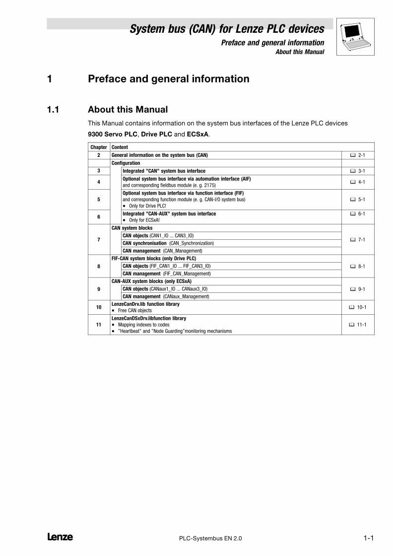
This Manual contains information on the system bus interfaces of the Lenze PLC devices
9300 Servo PLC, Drive PLC and ECSxA.
Chapter Content
2 General information on the system bus (CAN) � 2−1
Configuration
3 Integrated "CAN" system bus interface � 3−1
4Optional system bus interface via automation interface (AIF)
and corresponding fieldbus module (e. g. 2175)� 4−1
5
Optional system bus interface via function interface (FIF)
and corresponding function module (e. g. CAN−I/O system bus)
� Only for Drive PLC!
� 5−1
6Integrated "CAN−AUX" system bus interface
� Only for ECSxA!
� 6−1
7
CAN system blocks
� 7−1CAN objects (CAN1_IO ... CAN3_IO)
CAN synchronisation (CAN_Synchronization)
CAN management (CAN_Management)
8
FIF−CAN system blocks (only Drive PLC)
� 8−1CAN objects (FIF_CAN1_IO ... FIF_CAN3_IO)
CAN management (FIF_CAN_Management)
9
CAN−AUX system blocks (only ECSxA)
� 9−1CAN objects (CANaux1_IO ... CANaux3_IO)
CAN management (CANaux_Management)
10LenzeCanDrv.lib function library
� Free CAN objects� 10−1
11
LenzeCanDSxDrv.libfunction library
� Mapping indexes to codes
� "Heartbeat" and "Node Guarding"monitoring mechanisms
� 11−1

1.1 About this Manual
System bus (CAN) for Lenze PLC devicesPreface and general information
1−2 LPLC−Systembus EN 2.0
1.1.1 Conventions used in this Manual
This Manual uses the following conventions to distinguish between different types of information:
Variable identifier
... are presented in italics in the explanatory text:
� "Via wDrvNr..."
Tip!
Information about the conventions used for variables of Lenze system blocks, function blocks andfunctions can be obtained from the appendix of the DDS online documentation "Introduction intoIEC 61131−3 programming".The conventions ensure universal and uniform labelling and support thereadability of PLC programs.
Lenze functions/function blocks
... can be identified by their designation. They always start with an "L_":
� "The function L_CanInit ..."
� "The L_CanPdoTransmit FB..."
Program listings
... are specified in the "Courier" font, the keywords being printed bold:
� "IF (ReturnValue < 0) THEN..."

System bus (CAN) for Lenze PLC devicesPreface and general information
1.1 About this Manual
1−3L PLC−Systembus EN 2.0
1.1.2 Structure of the description
The descriptions of the individual functions/function blocks as well as of system blocks containedin this Manual have the same structure:
�
�
�
�
�
�
� Headline with SB identifier
� SB function and node number
� Short description of the SB and its most important features
� System block chart including all corresponding variables
� Input variables
� Output variables
� Table giving information about input and output variables:
� Identifier
� Data type
� Signal type
� Address
� Display code
� Display format
� Information
� Detailed functional description of the SB
Information on return values for a function
If it was not possible to carry out a function faultlessly, a negative return value is sent back,representing an error number.
� Each error number is assigned to a corresponding error cause in the Meaning column.
� If different error numbers (−1, −2, ...) may apply, a specific digit (1, 2, ...) in the Priority columnadditionally is assigned to the error number.
– The smaller this digit, the higher is the priority of the associated error number.
– If several error causes are available at the same time when a function is carried out, alwaysthe error number with the highest priority is returned by the function.

1.1 About this Manual
System bus (CAN) for Lenze PLC devicesPreface and general information
1−4 LPLC−Systembus EN 2.0
1.1.3 Pictographs used in this Manual
Pictographs
used
Signal words
Warning of
material damage
Stop! Warns of potential damage to material.
Possible consequences if disregarded:
Damage of the controller/drive system or its environment.
More notes Tip!
Note!
Indicates a tip or note.
1.1.4 Terminology used
Term In the following text used for
AIF Automation interface
DDS Drive PLC Developer Studio
FB Function block
FIF Function interface
GDC Global Drive Control (parameterisation program from Lenze)
Parameter codes Codes for setting the function of a function block
PLC � 9300 Servo PLC
� Drive PLC
� ECSxA
SB System block
System bus System bus (CAN): Lenze standard bus system similar to CANopen
System bus (CAN) for Lenze PLC devicesGeneral information
2−1l PLC−Systembus EN 2.0
2 General information on the system bus (CAN)
2.1 Introduction
All Lenze drive and automation systems are provided with an integrated system bus interface for thenetworking of control components on a field level.
Via the system bus interface, among other things process data and parameter data can beexchanged between the nodes. Furthermore the interface enables the connection of furthermodules, like for example decentralised terminals, operator and input devices, as well as externalcontrols and host systems.
The system bus interface transfers CAN objects following the CANopen communication profile(CiA DS301, version 4.01), which was developed under the umbrella association of the CiA (CAN inAutomation), complying with the CAL (CAN Application Layer).
System bus (CAN) for Lenze PLC devicesGeneral information
2−2 lPLC−Systembus EN 2.0
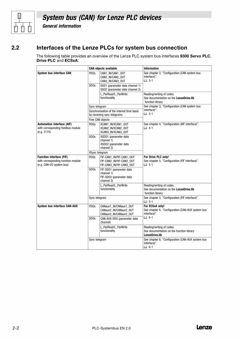
2.2 Interfaces of the Lenze PLCs for system bus connection
The following table provides an overview of the Lenze PLC system bus interfaces 9300 Servo PLC,Drive PLC and ECSxA:
CAN objects available Information
System bus interface CAN PDOs CAN1_IN/CAN1_OUT
CAN2_IN/CAN2_OUT
CAN3_IN/CAN3_OUT
See chapter 3, "Configuration (CAN system businterface)".
� 3−1
SDOs SDO1 (parameter data channel 1)
SDO2 (parameter data channel 2)
L_ParRead/L_ParWritefunctionality
Reading/writing of codes.
See documentation on the LenzeDrive.lib
function library
Sync telegram See chapter 3, "Configuration (CAN system businterface)".
� 3−1Synchronisation of the internal time basisby receiving sync telegrams
Free CAN objects
Automation interface (AIF)
with corresponding fieldbus module
(e.g. 2175)
PDOs XCAN1_IN/XCAN1_OUT
XCAN2_IN/XCAN2_OUT
XCAN3_IN/XCAN3_OUT
See chapter 4, "Configuration (AIF interface)".
� 4−1
SDOs XSDO1 (parameter datachannel 1)
XSDO2 (parameter datachannel 2)
XSync telegram
Function interface (FIF)
with corresponding function module
(e.g. CAN−I/O system bus)
PDOs FIF−CAN1_IN/FIF−CAN1_OUT
FIF−CAN2_IN/FIF−CAN2_OUT
FIF−CAN3_IN/FIF−CAN3_OUT
For Drive PLC only!
See chapter 5, "Configuration (FIF interface)".
� 5−1
SDOs FIF−SDO1 (parameter datachannel 1)
FIF−SDO2 (parameter datachannel 2)
L_ParRead/L_ParWritefunctionality
Reading/writing of codes.
See documentation on the LenzeDrive.lib
function library
Sync telegram See chapter 5, "Configuration (FIF interface)".
� 5−1
System bus interface CAN−AUX PDOs CANaux1_IN/CANaux1_OUT
CANaux2_IN/CANaux2_OUT
CANaux3_IN/CANaux3_OUT
For ECSxA only!
See chapter 6, "Configuration (CAN−AUX system businterface)".
� 6−1SDOs CAN−AUX−SDO (parameter datachannel)
L_ParRead/L_ParWritefunctionality
Reading/writing of codes.
See documentation on the function library
LenzeDrive.lib
Sync telegram See chapter 6, "Configuration (CAN−AUX system businterface)".
� 6−1
System bus (CAN) for Lenze PLC devicesGeneral information
2−3l PLC−Systembus EN 2.0
2.3 Identification of the nodes
Assign a node address − also called Node ID − in the range of 1 to 63 to each node within the systembus network as a definite identification.
� The same node address may not be assigned more than once within the network.
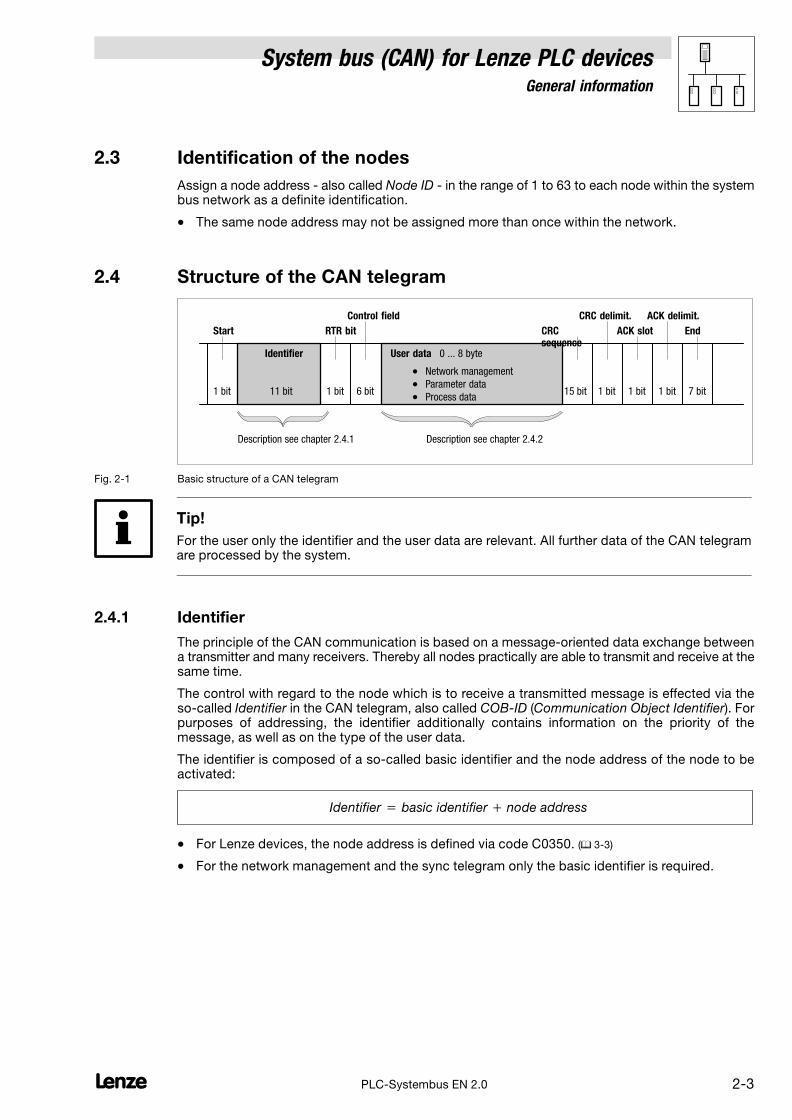
2.4 Structure of the CAN telegram
�1�bit 11�bit 1�bit 6�bit
0 ... 8 byte
15�bit
Start
Identifier
RTR bit
Control field
User data
CRCsequence
CRC delimit.
ACK slot
ACK delimit.
End
Description see chapter 2.4.1
� Network management
� Parameter data
� Process data
Description see chapter 2.4.2
�1�bit �1�bit �1�bit �7�bit
Fig. 2−1 Basic structure of a CAN telegram
Tip!
For the user only the identifier and the user data are relevant. All further data of the CAN telegramare processed by the system.
2.4.1 Identifier
The principle of the CAN communication is based on a message−oriented data exchange betweena transmitter and many receivers. Thereby all nodes practically are able to transmit and receive at thesame time.
The control with regard to the node which is to receive a transmitted message is effected via theso−called Identifier in the CAN telegram, also called COB−ID (Communication Object Identifier). Forpurposes of addressing, the identifier additionally contains information on the priority of themessage, as well as on the type of the user data.
The identifier is composed of a so−called basic identifier and the node address of the node to beactivated:
Identifier � basic identifier � node address
� For Lenze devices, the node address is defined via code C0350. (� 3−3)
� For the network management and the sync telegram only the basic identifier is required.
System bus (CAN) for Lenze PLC devicesGeneral information
2−4 lPLC−Systembus EN 2.0
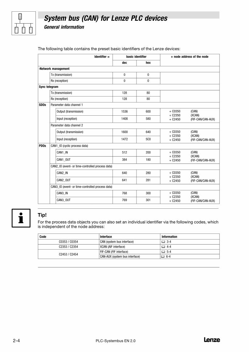
The following table contains the preset basic identifiers of the Lenze devices:
Identifier = basic identifier + node address of the node
dec hex
·Network management
Tx (transmission) 0 0
Rx (reception) 0 0
Sync telegram
Tx (transmission) 128 80
Rx (reception) 128 80
SDOs Parameter data channel 1
Output (transmission) 1536 600 + C0350
+ C2350
+ C2450
(CAN)
(XCAN)
(FIF−CAN/CAN−AUX)Input (reception) 1408 580
Parameter data channel 2
Output (transmission) 1600 640 + C0350
+ C2350
+ C2450
(CAN)
(XCAN)
(FIF−CAN/CAN−AUX)Input (reception) 1472 5C0
PDOs CAN1_IO (cyclic process data)
CAN1_IN 512 200 + C0350
+ C2350
+ C2450
(CAN)
(XCAN)
(FIF−CAN/CAN−AUX)CAN1_OUT 384 180
CAN2_IO (event− or time−controlled process data)
CAN2_IN 640 280 + C0350
+ C2350
+ C2450
(CAN)
(XCAN)
(FIF−CAN/CAN−AUX)CAN2_OUT 641 281
CAN3_IO (event− or time−controlled process data)
CAN3_IN 768 300 + C0350
+ C2350
+ C2450
(CAN)
(XCAN)
(FIF−CAN/CAN−AUX)CAN3_OUT 769 301
Tip!
For the process data objects you can also set an individual identifier via the following codes, whichis independent of the node address:
Code Interface Information
C0353 / C0354 CAN (system bus interface) � 3−4
C2353 / C2354 XCAN (AIF interface) � 4−4
C2453 / C2454FIF−CAN (FIF interface) � 5−4
CAN−AUX (system bus interface) � 6−4

System bus (CAN) for Lenze PLC devicesGeneral information
2−5l PLC−Systembus EN 2.0
2.4.2 User data
Via the user data area of the CAN telegram, three different types of data are transported:
Data type Information
Network management data Information on the structure of communication via the CAN network. Chapter 2.5(� 2−6)
Process data Process data are data for control−oriented concerns, e. g. setpoints and actualvalues.
� Process data are transmitted as so−called PDOs (Process Data Objects) with ahigh priority.
� Process data are processed more quickly by the PLC as parameter data.
� The transmission and reception of the process data is effected by the use ofspecific system blocks or the free CAN objects:
Chapter 2.6(� 2−7)
CAN
(integrated
system bus interface)
SB CAN1_IO for cyclic process data (sync−controlled)
9300 Servo PLC:
Drive PLC:
ECSxA:
Chapter 7.1(� 7−1)
Chapter 7.2(� 7−6)
Chapter 7.2(� 7−6)
SB CAN2_IO for event− or time−controlled process data Chapter 7.4(� 7−14)
SB CAN3_IO for event− or time−controlled process data Chapter 7.5(� 7−17)
XCAN
(automation interface)
SB AIF1_IO_AutomationInterface
for cyclic process data (sync−controlled)
See Manual
� 9300 Servo PLC
� Drive PLC
� ECSxASB AIF2_IO_AutomationInterface
for event− or time−controlled process data
SB AIF3_IO_AutomationInterface
for event− or time−controlled process data
FIF−CAN
(function interface,
Drive PLC only!
SB FIF_CAN1_IO for cyclic process data (sync−controlled) Chapter 8.1(� 8−1)
SB FIF_CAN2_IO for event− or time−controlled process data Chapter 8.2(� 8−1)
SB FIF_CAN3_IO for event− or time−controlled process data Chapter 8.3(� 8−1)
CAN−AUX
(integrated
system bus interface,
ECSxA only)
SB CANaux1_IO for cyclic process data (sync−controlled) Chapter 9.1(� 9−1)
SB CANaux2_IO for event− or time−controlled process data Chapter 9.2(� 9−1)
SB CANaux3_IO for event− or time−controlled process data Chapter 9.3(� 9−1)
Free CAN objects By using the functions/function blocks of the LenzeCanDrv.lib functionlibrary, so−called "free CAN objects" additionally can be added to thefixedly integrated CAN objects.
Chapter 10(� 10−1)
Parameter data For Lenze devices, parameter data are the so−called codes.
� Parameter settings for instance are carried out in the case of a one−timesetting of the system during commissioning, or in the case of a materialchange of the production machine.
� Parameter data are transferred as so−called SDOs (Service Data Objects) viathe CAN network and are acknowledged by the receiver, i. e. the transmitterreceives a feedback on whether the transmission was successful.
Chapter 2.7(� 2−11)
System bus (CAN) for Lenze PLC devicesGeneral information
2−6 lPLC−Systembus EN 2.0
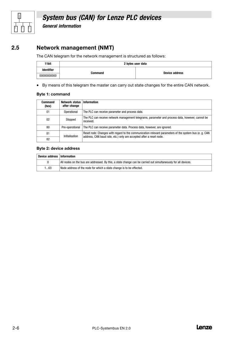
2.5 Network management (NMT)
The CAN telegram for the network management is structured as follows:
11bit 2 bytes user data
IdentifierCommand Device address
00000000000
� By means of this telegram the master can carry out state changes for the entire CAN network.
Byte 1: command
Command
(hex)
Network statusafter change
Information
01 Operational The PLC can receive parameter and process data.
02 StoppedThe PLC can receive network management telegrams, parameter and process data, however, cannot bereceived.
80 Pre−operational The PLC can receive parameter data. Process data, however, are ignored.
81Initialisation
Reset rode: Changes with regard to the communication−relevant parameters of the system bus (e. g. CANaddress, CAN baud rate, etc.) only are accepted after a reset node.
82
Byte 2: device address
Device address Information
0 All nodes on the bus are addressed. By this, a state change can be carried out simultaneously for all devices.
1...63 Node address of the node for which a state change is to be effected.

System bus (CAN) for Lenze PLC devicesGeneral information
2−7l PLC−Systembus EN 2.0
2.6 Transmission of process data
Process data are data for control−oriented concerns, e. g. setpoints and actual values.
� Process data are transferred as so−called PDOs (Process Data Objects) with a high priority viathe system bus.
� Transmitting and receiving the process data is effected by the use of specific system blocks:
CAN
(integrated)
XCAN
(AIF interface)
FIF−CAN
(FIF interface)
For Drive PLC only!
CANaux
For ECSxA only! Information
CAN1_IO AIF1_IO_AutomationInterface FIF_CAN1_IO CANaux1_IO Cyclic process data (sync−controlled)
CAN2_IO AIF2_IO_AutomationInterface FIF_CAN2_IO CANaux2_IO Event− or time−controlled process data
CAN3_IO AIF3_IO_AutomationInterface FIF_CAN3_IO CANaux3_IO Event− or time−controlled process data
Tip!
In the following subchapters you’ll receive further information on the CAN1_IO ... CAN3_IO processdata objects of the CAN interface. This information also applies to the process data objects of theAIF−, FIF− and CAN−AUX interface!
2.6.1 Process data channels
Process data channel 1: CAN1_IO
The CAN1_IO SB can be used for the data exchange of cyclic process data (e. g. setpoints andactual values) with a higher−level host system.
cyclic process data (sync−controlled)process data channel 1
CAN1_IN
CAN1_OUT
Host
Fig. 2−2 Process data channel 1 (CAN1_IO) for the cyclic data exchange

System bus (CAN) for Lenze PLC devicesGeneral information
2−8 lPLC−Systembus EN 2.0
Process data channel 2/3: CAN2_IO/CAN3_IO
The SBs CAN2_IO and CAN3_IO are designed for the data exchange of event− or time−controlledprocess data among the devices. These SBs can also be used for the data exchange withdecentralised input/output terminals and higher−level host systems.
event−controlled process dataprocess data channel 2
CAN2_OUT
CAN2_IN
event−controlled process dataprocess data channel 3
CAN2_IN
CAN2_OUT
CAN3_OUT
CAN3_IN
CAN3_IN
CAN3_OUT
E. g. decentralised terminals
Fig. 2−3 Process data channels 2 and 3 (CAN2_IO/CAN3_IO) for the event− or time−controlled data exchange
Tip!
Detailed information on the CAN1_IO ... CAN3_IO CAN objects integrated in the PLC can be foundin the chapter 7, "CAN system blocks":
CAN1_IO for cyclic process data (sync−controlled)
9300 Servo PLC:
Drive PLC:
ECSxA:
Chapter 7.1(� 7−1)
Chapter 7.2(� 7−6)
Chapter 7.3(� 7−10)
CAN2_IO for event− or time−controlled process data Chapter 7.4(� 7−14)
CAN3_IO for event− or time−controlled process data Chapter 7.5(� 7−17)
System bus (CAN) for Lenze PLC devicesGeneral information
2−9l PLC−Systembus EN 2.0
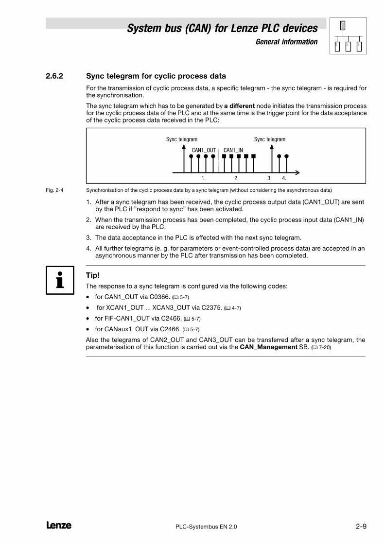
2.6.2 Sync telegram for cyclic process data
For the transmission of cyclic process data, a specific telegram − the sync telegram − is required forthe synchronisation.
The sync telegram which has to be generated by a different node initiates the transmission processfor the cyclic process data of the PLC and at the same time is the trigger point for the data acceptanceof the cyclic process data received in the PLC:
Sync telegram Sync telegram
CAN1_OUT CAN1_IN
1. 2. 3. 4.
Fig. 2−4 Synchronisation of the cyclic process data by a sync telegram (without considering the asynchronous data)
1. After a sync telegram has been received, the cyclic process output data (CAN1_OUT) are sentby the PLC if "respond to sync" has been activated.
2. When the transmission process has been completed, the cyclic process input data (CAN1_IN)are received by the PLC.
3. The data acceptance in the PLC is effected with the next sync telegram.
4. All further telegrams (e. g. for parameters or event−controlled process data) are accepted in anasynchronous manner by the PLC after transmission has been completed.
Tip!
The response to a sync telegram is configured via the following codes:
� for CAN1_OUT via C0366. (� 3−7)
� for XCAN1_OUT ... XCAN3_OUT via C2375. (� 4−7)
� for FIF−CAN1_OUT via C2466. (� 5−7)
� for CANaux1_OUT via C2466. (� 5−7)
Also the telegrams of CAN2_OUT and CAN3_OUT can be transferred after a sync telegram, theparameterisation of this function is carried out via the CAN_Management SB. (� 7−20)
System bus (CAN) for Lenze PLC devicesGeneral information
2−10 lPLC−Systembus EN 2.0
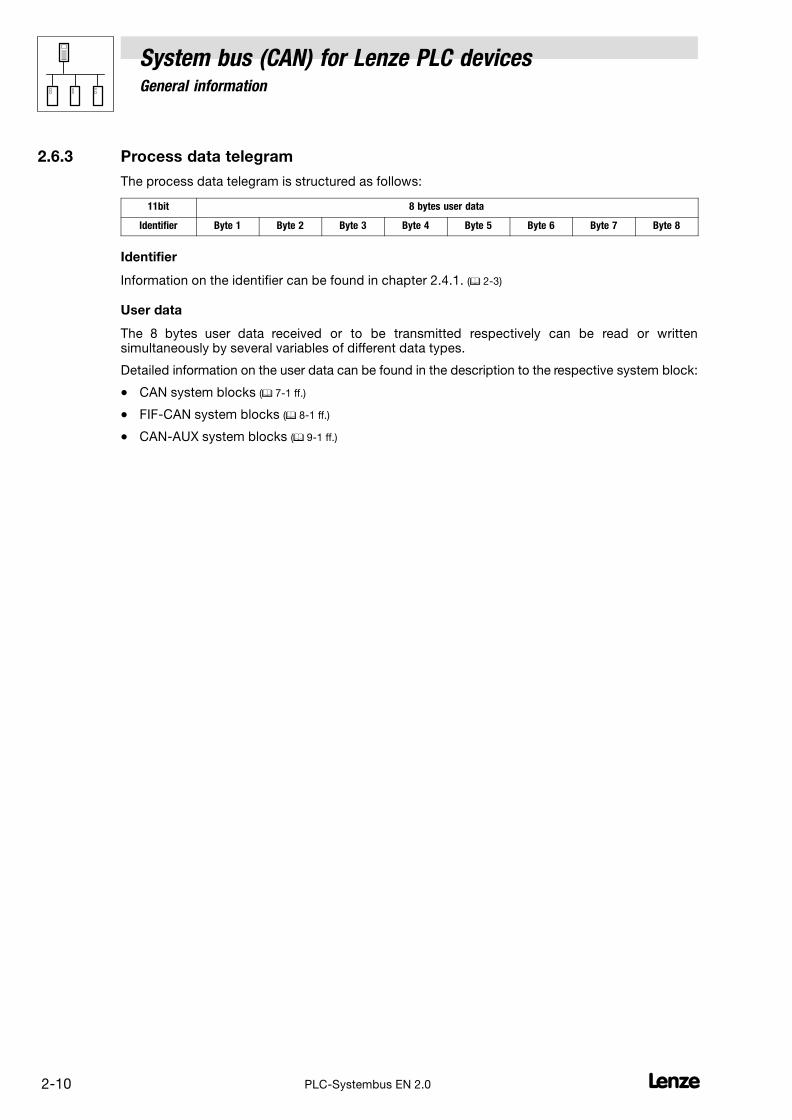
2.6.3 Process data telegram
The process data telegram is structured as follows:
11bit 8 bytes user data
Identifier Byte 1 Byte 2 Byte 3 Byte 4 Byte 5 Byte 6 Byte 7 Byte 8
Identifier
Information on the identifier can be found in chapter 2.4.1. (� 2−3)
User data
The 8 bytes user data received or to be transmitted respectively can be read or writtensimultaneously by several variables of different data types.
Detailed information on the user data can be found in the description to the respective system block:
� CAN system blocks (� 7−1 ff.)
� FIF−CAN system blocks (� 8−1 ff.)
� CAN−AUX system blocks (� 9−1 ff.)

System bus (CAN) for Lenze PLC devicesGeneral information
2−11l PLC−Systembus EN 2.0
2.7 Transmitting parameter data
For Lenze devices, parameter data are the so−called codes.
� Parameter settings for instance are carried out in the case of a one−time setting of the systemduring commissioning, or in the case of a material change of the production machine.
� Parameter data are transferred as so−called SDOs (Service Data Objects) via the system busand are acknowledged by the receiver, i. e. the transmitter receives a feedback on whether thetransmission was successful.
2.7.1 Parameter data telegram
The telegram for parameter data is structured as follows:
11bit 8 bytes user data
IdentifierCommand
code
IndexSubindex Data 1 Data 2 Data 3 Data 4
Low byte High byte
� In the following subchapters the different components of the telegram are explained in detail.
� An example for writing a parameter can be found in chapter 2.7.2. (� 2−15)
� An example for reading a parameter can be found in chapter 2.7.3. (� 2−17)
2.7.1.1 Identifier
IdentifierCommand
code
IndexSubindex Data 1 Data 2 Data 3 Data 4
Low byte High byte
For the transmission of parameter data, two parameter data channels are provided, which areaddressed via the identifier:
Identifier = basic identifier + node address of the node
dec hex
SDOs Parameter data channel 1
Output (transmission) 1536 600 + C0350
+ C2350
+ C2450
(CAN)
(XCAN)
(FIF−CAN/CANaux)Input (reception) 1408 580
Parameter data channel 2
Output (transmission) 1600 640 + C0350
+ C2350
+ C2450
(CAN)
(XCAN)
(FIF−CAN/CANaux)Input (reception) 1472 5C0
Tip!
Between the identifiers for parameter data channels 1 and 2 there respectively is an offset of 64:
� Output of parameter data channel 1 = 1536
� Output of parameter data channel 2 = 1536 + 64 = 1600

System bus (CAN) for Lenze PLC devicesGeneral information
2−12 lPLC−Systembus EN 2.0
2.7.1.2 Command code
IdentifierCommand
code
IndexSubindex Data 1 Data 2 Data 3 Data 4
Low byte High byte
Among other things, the command code contains the command to be carried out as well asinformation on the parameter data length, and is structured as follows:
Bit 7 (MSB) Bit 6 Bit 5 Bit 4 Bit 3 Bit 2 Bit 1 Bit 0
Command Command Specifier (cs) Length e s
Write request 0 0 1 000 = 4 bytes
01 = 3 bytes
10 = 2 bytes
11 = 1 byte
1 1
Write response 0 1 1 0 0 0
Read request 0 1 0 0 0 0
Read response 0 1 0 0 1 1
Error Response 1 0 0 0 0 0 0 0
Command code for parameters with 1, 2, or 4 bytes data length:
4 byte data
(32 bit)
2 byte data
(16 bit)
1 byte data
(8 bit)
Command hex dec hex dec hex dec Information
Write Request 23 35 2B 43 2F 47 Send parameter to a node
Write Response 60 96 60 64 60 96 Node response to "write request" (acknowledgement)
Read Request 40 64 40 64 40 64 Request for reading a parameter of a node
Read Response 43 67 4B 75 4F 79 Response to the read request with an actual value
Error Response 80 128 80 128 80 128 Node reports an error with regard to communication
"Error Response" command
In the case of this error, an "Error Response" is generated by the node that is addressed.
� This telegram in data 4 always contains the value "6", and in data 3 an error code:
Error Response command code Data 3 Data 4 Error message
80hex
3
6
Access denied
5 Incorrect subindex
6 Incorrect index
C0hex 8Job was not edited
(for 8200 vector + FIF module)

System bus (CAN) for Lenze PLC devicesGeneral information
2−13l PLC−Systembus EN 2.0
2.7.1.3 Addressing the parameter (index/subindex)
IdentifierCommand
code
IndexSubindex Data 1 Data 2 Data 3 Data 4
Low byte High byte
The addressing of the parameter or of the Lenze code which is to be read or written is effected viathe index of the telegram:
Index � 24575 � Lenze code number
� The value for the index is to be entered divided into a low and a high byte in the left−justifiedIntel format (see example).
� If a subcode is to be addressed, enter the number of the respective subcode in the subindexof the telegram.
� For codes without subcodes, the subindex always receives the value "0".
� The index for Lenze codes is between 40C0hex (16576) and 5FFFhex (24575).
Lenze code Index
dec hex
C0000 24575 5FFF
... ... ...
C7999 16576 40C0
Tip!
For converting a code number to the corresponding index, the function L_FUNCodeIndexConv inthe LenzeDrive.lib function library is provided to you.
Example:
Subcode 1 of code C0168 (fault messages) is to be addressed:
Index � 24575 � 168 � 24407 � 5F57hex
11bit 8 bytes user data
IdentifierCommand
code
IndexSubindex Data 1 Data 2 Data 3 Data 4
Low byte High byte
57hex 5Fhex 1hex

System bus (CAN) for Lenze PLC devicesGeneral information
2−14 lPLC−Systembus EN 2.0
2.7.1.4 Data of the parameter (data 1 ... data 4)
IdentifierCommand
code
IndexSubindex Data 1 Data 2 Data 3 Data 4
Low byte High byte
For the data of the parameter up to 4 bytes (data 1 ... data 4) are provided.
� The data are presented in the left−justified Intel format with data 1 as LSB and data 4 as MSB(see example).
Example:
For a code in the "Fixed32" data format, the value "20" is to be transmitted.
� "Fixed32" is a fixed point format with 4 decimal positions. Therefore the value has to bemultiplied by 10000:
Data1...4 � 20 � 10000 � 200000 � 00 03 0D 40hex
11bit 8 bytes user data
IdentifierCommand
code
IndexSubindex Data 1 Data 2 Data 3 Data 4
Low byte High byte
40hex 0Dhex 03hex 00hex
(LSB) (MSB)
Tip!
The parameters of the Lenze devices are stored in different formats.
Detailed information on this subject can be found in the Manual for the respective PLC in the chapter"Appendix − Table of attributes".

System bus (CAN) for Lenze PLC devicesGeneral information
2−15l PLC−Systembus EN 2.0
2.7.2 Writing parameters (example)
Task
The acceleration time (C0012) of the controller with the node address 1 is to be set to 20 s via theparameter data channel 1.
Telegram to the controller
Formula Information
Identifier = basic identifier + node address
= 1536 + 1
= 1537
� Basic identifier for parameter data channel 1 (output) = 1536
� Node address of the controller = 1
Command code = 23hex � Command "Write Request" (send parameter to controller)
Index = 24575 − number of the Lenze code
= 24575 − 12
= 24563
= 5F F3hex
� Code = C0012 (acceleration time)
Subindex = 0 � Subcode = 0 (no subcode)
Data 1 ... 4 = 20 x 10000
= 200000
= 00 03 0D 40hex
� Value = 20 s
� Fixed32 data format (4 fixed decimal positions); multiply value by 10000
11bit 8 bytes user data
IdentifierCommand
code
IndexSubindex Data 1 Data 2 Data 3 Data 4
Low byte High byte
1537 23hex F3hex 5Fhex 0 40hex 0Dhex 03hex 00hex
(LSB) (MSB)
Identifier = 1537
L
SDO 1 / Node-ID 1
Identifier = 1409
Write Request(C0012 = 20 s)
Write Response
Fig. 2−5 Writing parameters

System bus (CAN) for Lenze PLC devicesGeneral information
2−16 lPLC−Systembus EN 2.0
Telegram from controller (acknowledgement if carried out correctly)
Formula Information
Identifier = basic identifier + node address
= 1408 + 1
= 1409
� Basic identifier for parameter data channel 1 (input) = 1408
� Node address of the controller = 1
Command code = 60hex � "Write Response" command (acknowledgement by the controller)
Index = index of the read request
Subindex = subindex of the read request
Data 1 ... 4 = 0 � Acknowledgement only
11bit 8 bytes user data
IdentifierCommand
code
IndexSubindex Data 1 Data 2 Data 3 Data 4
Low byte High byte
1409 60hex F3hex 5Fhex 0 0 0 0 0

System bus (CAN) for Lenze PLC devicesGeneral information
2−17l PLC−Systembus EN 2.0
2.7.3 Reading a parameter (example)
Task
The heatsink temperature (C0061) of the controller with the node address 5 is to be read via theparameter data channel 1.
Telegram to the controller
Formula Information
Identifier = basic identifier + node address
= 1536 + 5
= 1541
� Basic identifier for parameter data channel 1 (output) = 1536
� Node address of the controller = 5
Command code = 40hex � Command "Read Request" (request to read a parameter from thecontroller)
Index = 24575 − number of the Lenze code
= 24575 − 61
= 24514
= 5F C2hex
� Code = C0061 (heatsink temperature)
Subindex = 0 � Subcode = 0 (no subcode)
Data 1 ... 4 = 0 � Read request only
11bit 8 bytes user data
IdentifierCommand
code
IndexSubindex Data 1 Data 2 Data 3 Data 4
Low byte High byte
1541 40hex C2hex 5Fhex 0 0 0 0 0
Identifier = 1541
L
Identifier = 1413
Read Request(C0061 = ???)
Read Response(C0061 = 43 ºC)
SDO 1 / Node-ID 5
Fig. 2−6 Reading parameters
System bus (CAN) for Lenze PLC devicesGeneral information
2−18 lPLC−Systembus EN 2.0
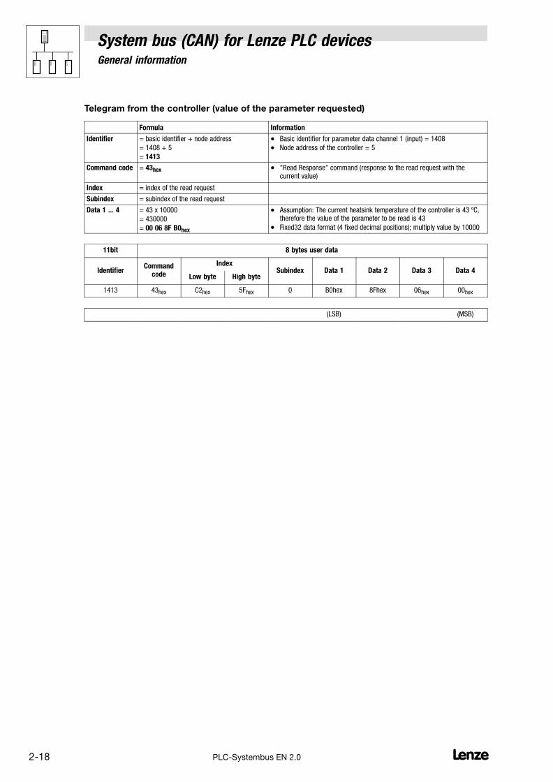
Telegram from the controller (value of the parameter requested)
Formula Information
Identifier = basic identifier + node address
= 1408 + 5
= 1413
� Basic identifier for parameter data channel 1 (input) = 1408
� Node address of the controller = 5
Command code = 43hex � "Read Response" command (response to the read request with thecurrent value)
Index = index of the read request
Subindex = subindex of the read request
Data 1 ... 4 = 43 x 10000
= 430000
= 00 06 8F B0hex
� Assumption: The current heatsink temperature of the controller is 43 ºC,therefore the value of the parameter to be read is 43
� Fixed32 data format (4 fixed decimal positions); multiply value by 10000
11bit 8 bytes user data
IdentifierCommand
code
IndexSubindex Data 1 Data 2 Data 3 Data 4
Low byte High byte
1413 43hex C2hex 5Fhex 0 B0hex 8Fhex 06hex 00hex
(LSB) (MSB)
System bus (CAN) for Lenze PLC devicesGeneral information
2−19l PLC−Systembus EN 2.0
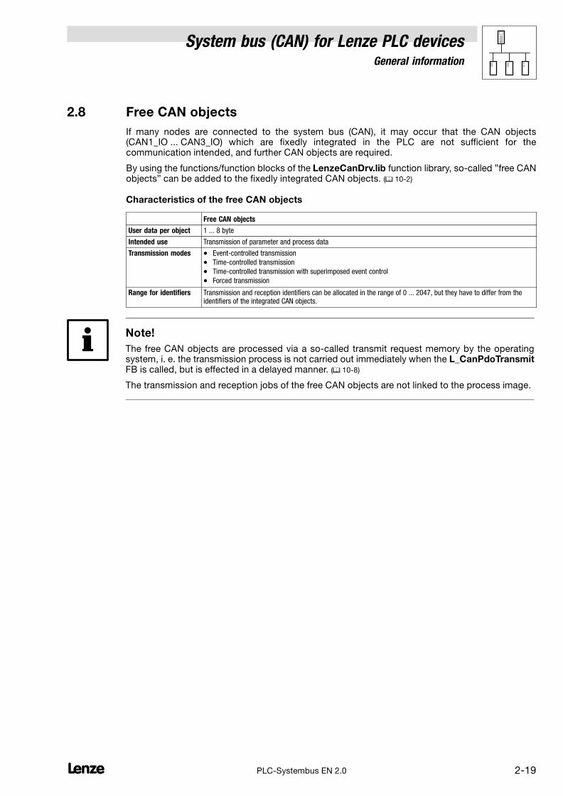
2.8 Free CAN objects
If many nodes are connected to the system bus (CAN), it may occur that the CAN objects(CAN1_IO ... CAN3_IO) which are fixedly integrated in the PLC are not sufficient for thecommunication intended, and further CAN objects are required.
By using the functions/function blocks of the LenzeCanDrv.lib function library, so−called "free CANobjects" can be added to the fixedly integrated CAN objects. (� 10−2)
Characteristics of the free CAN objects
Free CAN objects
User data per object 1 ... 8 byte
Intended use Transmission of parameter and process data
Transmission modes � Event−controlled transmission
� Time−controlled transmission
� Time−controlled transmission with superimposed event control
� Forced transmission
Range for identifiers Transmission and reception identifiers can be allocated in the range of 0 ... 2047, but they have to differ from theidentifiers of the integrated CAN objects.
Note!
The free CAN objects are processed via a so−called transmit request memory by the operatingsystem, i. e. the transmission process is not carried out immediately when the L_CanPdoTransmitFB is called, but is effected in a delayed manner. (� 10−8)
The transmission and reception jobs of the free CAN objects are not linked to the process image.

System bus (CAN) for Lenze PLC devicesGeneral information
2−20 lPLC−Systembus EN 2.0
2.9 Application recommendations for the different CAN objects
The following table provides a comparison of the different CAN objects and their specificcharacteristics:
CAN object Process datatransmission
Linked to theprocess image
Sync telegramrequired1)
Application recommendation
CAN1_IO � � � Data exchange
� of position setpoints/actual values
� of speed setpoints for servo applicationsCAN2_IO � �
CAN3_IO � �
XCAN1_IO � � �
XCAN2_IO � �
XCAN3_IO � �
FIF_CAN1_IO � � �
FIF_CAN2_IO � �
FIF_CAN3_IO � �
CANaux1_IO � � �
CANaux2_IO � �
CANaux3_IO � �
Free CAN objects � Data exchange
� of setpoints/actual values
� with analog terminal I/Os
1) Sync telegram required for the function of the respective CAN1 object
System bus (CAN) for Lenze PLC devicesGeneral information
2−21l PLC−Systembus EN 2.0
2.10 Monitoring mechanisms
In the CANopen communication profile (CiA DS301, version 4.01) two optional monitoringmechanisms for ensuring the function of system bus nodes are specified, "Heartbeat" and "NodeGuarding".
Note!
The "Heartbeat" and "Node Guarding" monitoring mechanisms are supported by the9300 Servo PLC, Drive, PLC and by the ECSxA axis module as of V6.0.
The initialisation and execution of the monitoring mechanisms is carried out by means of thefunctions/function blocks of the LenzeCanDSxDrv.lib function library. (� 11−1)
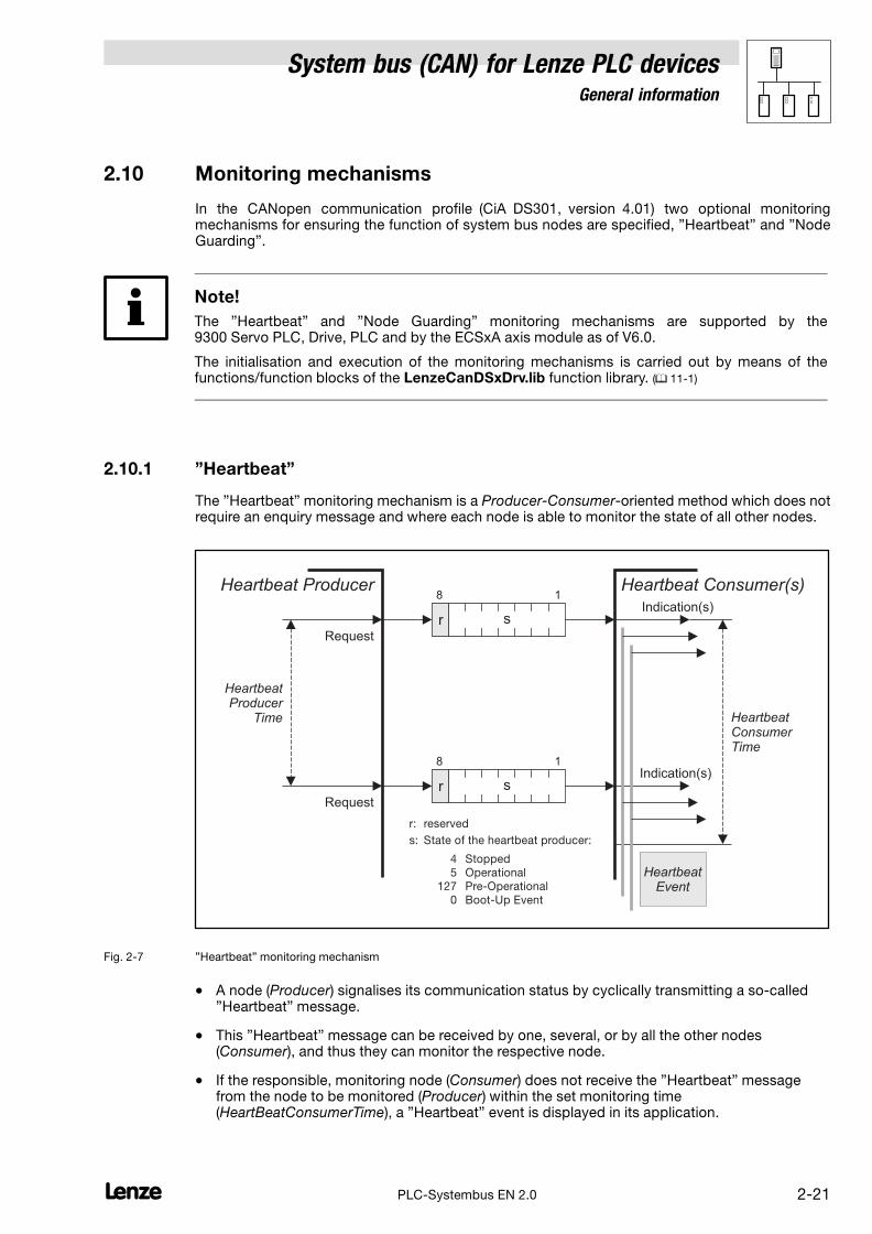
2.10.1 "Heartbeat"
The "Heartbeat" monitoring mechanism is a Producer−Consumer−oriented method which does notrequire an enquiry message and where each node is able to monitor the state of all other nodes.
Request
Request
Indication(s)
HeartbeatProducer
Time
Heartbeat Producer Heartbeat Consumer(s)
r s
HeartbeatEvent
HeartbeatConsumerTime
18
r s
18Indication(s)
r:
Stopped
Operational
Pre-Operational
Boot-Up Event
reserved
s: State of the heartbeat producer:
4
5
127
0
Fig. 2−7 "Heartbeat" monitoring mechanism
� A node (Producer) signalises its communication status by cyclically transmitting a so−called"Heartbeat" message.
� This "Heartbeat" message can be received by one, several, or by all the other nodes(Consumer), and thus they can monitor the respective node.
� If the responsible, monitoring node (Consumer) does not receive the "Heartbeat" messagefrom the node to be monitored (Producer) within the set monitoring time(HeartBeatConsumerTime), a "Heartbeat" event is displayed in its application.

System bus (CAN) for Lenze PLC devicesGeneral information
2−22 lPLC−Systembus EN 2.0
2.10.2 "Node Guarding"
In contrast to the "Heartbeat" monitoring mechanism, for the "Node Guarding" an enquiry messagefrom the monitoring node (NMT Master) is required.
NodeLife
Time
NodeGuarding
Event
Indication
Response
Confirmation
Confirmation
Response
Request
Request
Indication
NodeGuard
Time
NMT Master NMT Slave
RTR
t s
t s
RTR
LifeGuarding
Event
NodeLifeTime
18
18
t:
Stopped
Operational
Pre-Operational
Boot-Up Event
Toggle bit
s: NMT Slave state:
4
5
127
0
Fig. 2−8 "Node guarding" monitoring mechanism
� The NMT master monitors each of the nodes to be monitored (NMT slave) cyclically using anode−specific "Remote Transmission Request" telegram.
� The NMT slave to be monitored returns its communication status as a response to thisrequest.
� If the NMT master does not receive the message from the NMT Slave) to be monitored withinthe set monitoring time (NodeLifeTime|, a "Node Guarding" event is displayed in itsapplication.
� For the NMT slave to be monitored, however, a "Life Guarding" event is activated if its statushas not been enquired by the monitoring NMT master for longer than its "Node Life Time".
System bus (CAN) for Lenze PLC devices"CAN" system bus interface configuration
3−1l PLC−Systembus EN 2.0
3 Configuration (system bus − CAN interface)
Tip!
Changes with regard to the CAN baud rate, the CAN addresses, and the identifiers for PDOs onlyare accepted after a reset node.
A reset node can be effected by
� Reconnection of the mains
� Reset node command via NMT command. (� 2−6)
� Reset node via C0358 (� 3−8)
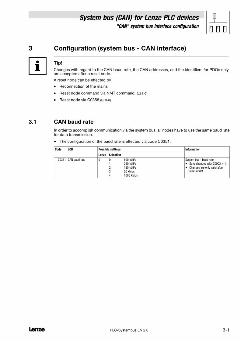
3.1 CAN baud rate
In order to accomplish communication via the system bus, all nodes have to use the same baud ratefor data transmission.
� The configuration of the baud rate is effected via code C0351:
Code LCD Possible settings Information
Lenze Selection
C0351 CAN baud rate 0 0 500 kbit/s
1 250 kbit/s
2 125 kbit/s
3 50 kbit/s
4 1000 kbit/s
System bus − baud rate
� Save changes with C0003 = 1.
� Changes are only valid afterreset node!
System bus (CAN) for Lenze PLC devices"CAN" system bus interface configuration
3−2 lPLC−Systembus EN 2.0
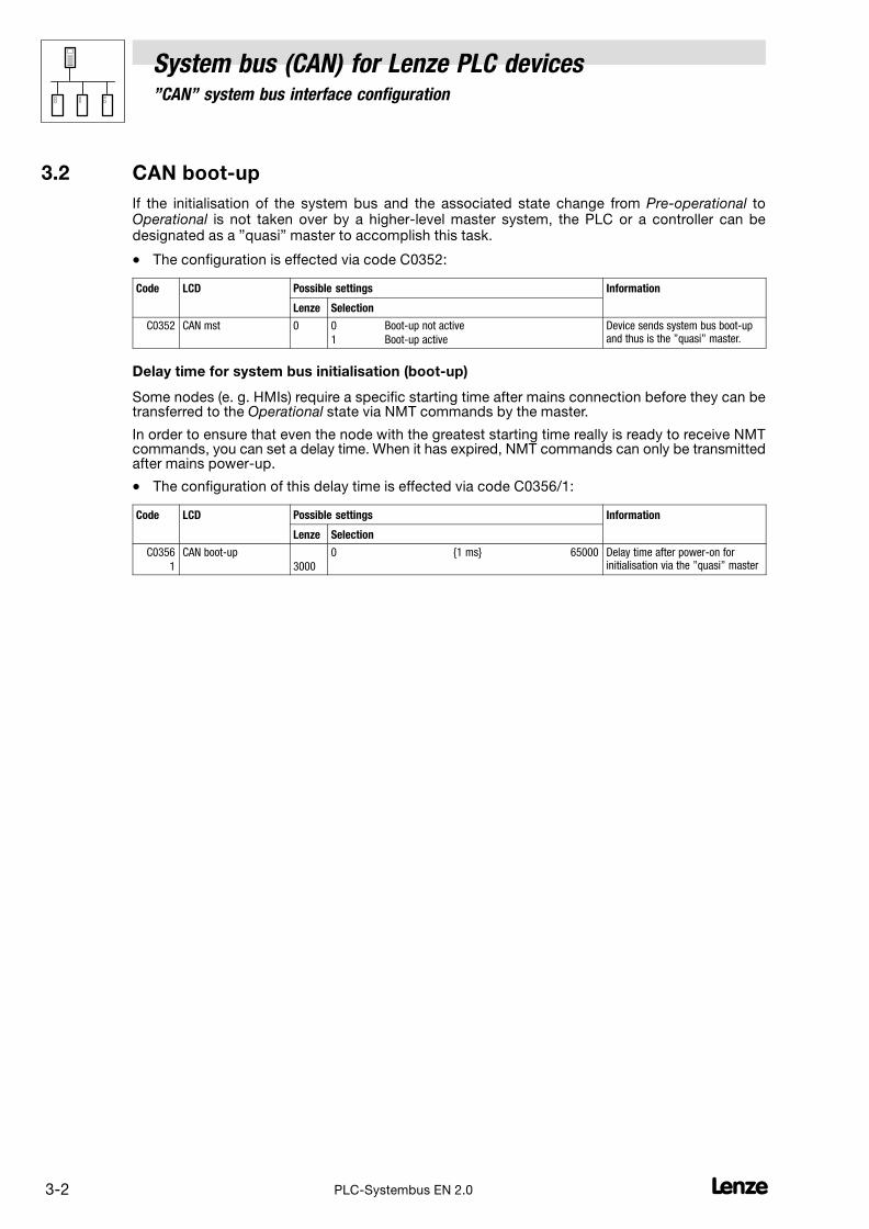
3.2 CAN boot−up
If the initialisation of the system bus and the associated state change from Pre−operational toOperational is not taken over by a higher−level master system, the PLC or a controller can bedesignated as a "quasi" master to accomplish this task.
� The configuration is effected via code C0352:
Code LCD Possible settings Information
Lenze Selection
C0352 CAN mst 0 0 Boot−up not active
1 Boot−up active
Device sends system bus boot−upand thus is the "quasi" master.
Delay time for system bus initialisation (boot−up)
Some nodes (e. g. HMIs) require a specific starting time after mains connection before they can betransferred to the Operational state via NMT commands by the master.
In order to ensure that even the node with the greatest starting time really is ready to receive NMTcommands, you can set a delay time. When it has expired, NMT commands can only be transmittedafter mains power−up.
� The configuration of this delay time is effected via code C0356/1:
Code LCD Possible settings Information
Lenze Selection
C0356
1
CAN boot−up
3000
0 {1 ms} 65000 Delay time after power−on forinitialisation via the "quasi" master
System bus (CAN) for Lenze PLC devices"CAN" system bus interface configuration
3−3l PLC−Systembus EN 2.0
3.3 Node address (node ID)
Assign a node address − also called Node ID − within the range of 1 to 63 to each node within thesystem bus network as a definite identification.
� The same node address may not be assigned more than once within the network.
� The configuration of the node address for the PLC is carried out via code C0350:
Code LCD Possible settings Information
Lenze Selection
C0350 CAN address 1 1 {1} 63 System bus − node address
� Save changes with C0003 = 1.
� Changes are only valid afterreset node!
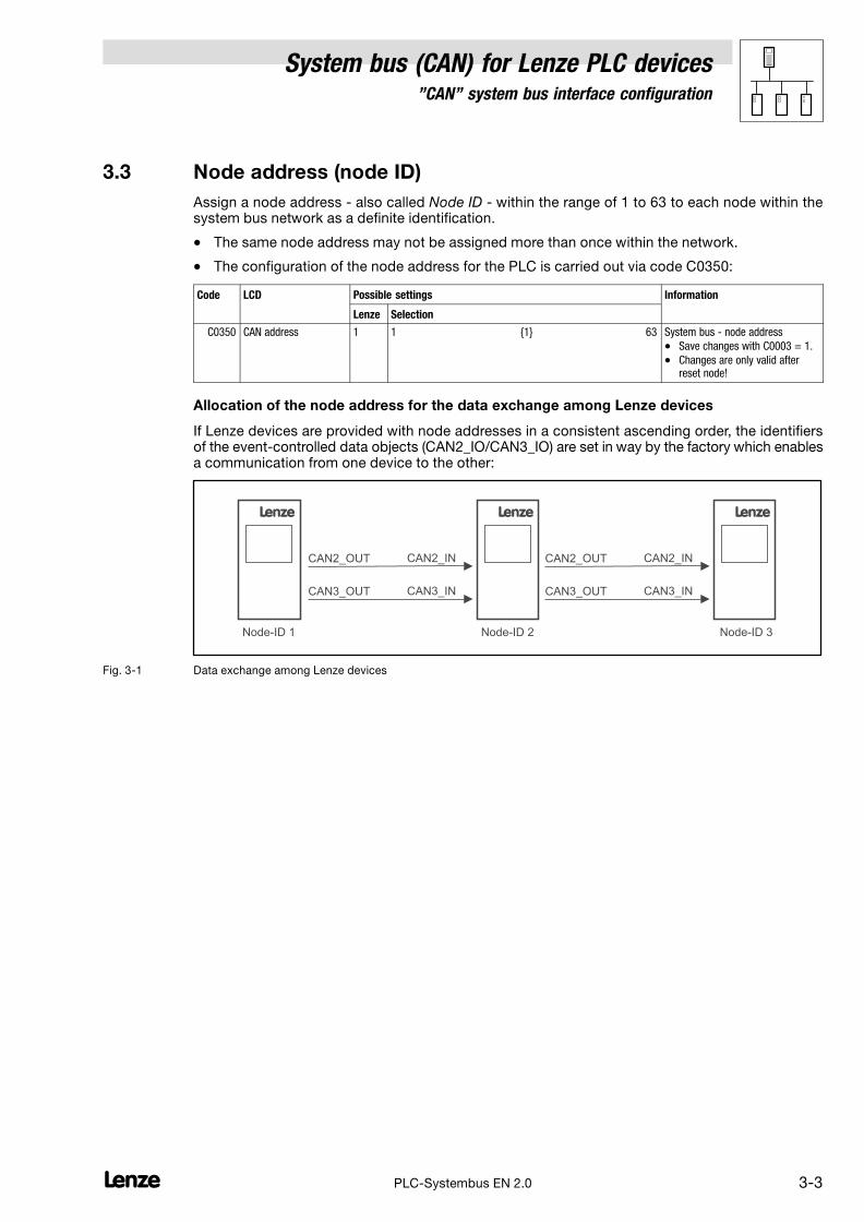
Allocation of the node address for the data exchange among Lenze devices
If Lenze devices are provided with node addresses in a consistent ascending order, the identifiersof the event−controlled data objects (CAN2_IO/CAN3_IO) are set in way by the factory which enablesa communication from one device to the other:
L
Node-ID 1
CAN2_OUT CAN2_IN
CAN3_OUT CAN3_IN
L
Node-ID 2
CAN2_OUT CAN2_IN
CAN3_OUT CAN3_IN
L
Node-ID 3
Fig. 3−1 Data exchange among Lenze devices

System bus (CAN) for Lenze PLC devices"CAN" system bus interface configuration
3−4 lPLC−Systembus EN 2.0
3.4 Identifiers of the process data objects
The identifiers for the CAN1_IO ... CAN3_IO process data objects are generated by the so−calledbasic identifier and the node address set in C0350:
Identifier � basic identifier � node address
Basic identifiers
dec hex
PDOs CAN1_IO (cyclic process data)
CAN1_IN 512 200
CAN1_OUT 384 180
CAN2_IO (event− or time−controlled process data)
CAN2_IN 640 280
CAN2_OUT 641 281
CAN3_IO (event− or time−controlled process data)
CAN3_IN 768 300
CAN3_OUT 769 301
3.4.1 Allocation of individual identifiers
For greater system bus networks with many nodes it may be reasonable to set individual identifiersfor the CAN1_IO ... CAN3_IO process data objects via C0353/C0354, which are independent of thenode address set in C0350:
1. Set C0353/x to "1".
– (x = subcode of the corresponding process data object):
Code LCD Possible settings Information
Lenze Selection
C0353 CAN addr sel 0 Identifier assignment under C0350 + basicidentifier
1 Identifier assignment under C0354/x
Source for the identifiers of theprocess data objects
� Save changes with C0003 = 1.
� Changes are only valid afterreset node!
1 CAN addr sel1 0 CAN1_IN/OUT
2 CAN addr sel2 0 CAN2_IN/OUT
3 CAN addr sel3 0 CAN3_IN/OUT
2. Set the value which added to "384" makes the desired identifier in C0354/x.
– (x = subcode of the corresponding process data object):
Code LCD Possible settings Information
Lenze Selection
C0354 CAN addr 1 {1} 512 Specification of individualidentifiers for the process dataobjects
1
2
3
4
5
6
IN1 addr2
OUT1 addr2
IN2 addr2
OUT2 addr2
IN3 addr2
OUT3 addr2
129
1
257
258
385
386
CAN1_IN
CAN1_OUT
CAN2_IN
CAN2_OUT
CAN3_IN
CAN3_OUT
System bus (CAN) for Lenze PLC devices"CAN" system bus interface configuration
3−5l PLC−Systembus EN 2.0
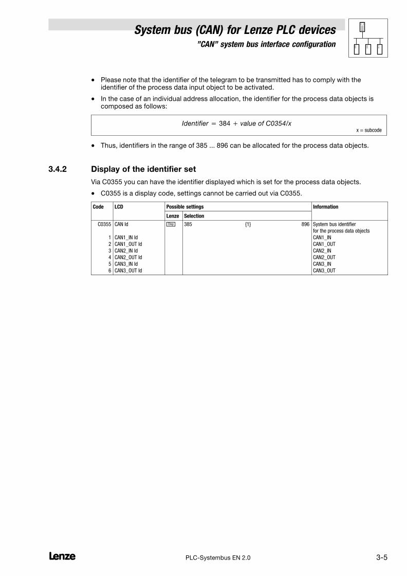
� Please note that the identifier of the telegram to be transmitted has to comply with theidentifier of the process data input object to be activated.
� In the case of an individual address allocation, the identifier for the process data objects iscomposed as follows:
Identifier � 384 � value of C0354/xx = subcode
� Thus, identifiers in the range of 385 ... 896 can be allocated for the process data objects.
3.4.2 Display of the identifier set
Via C0355 you can have the identifier displayed which is set for the process data objects.
� C0355 is a display code, settings cannot be carried out via C0355.
Code LCD Possible settings Information
Lenze Selection
C0355
1
2
3
4
5
6
CAN Id
CAN1_IN Id
CAN1_OUT Id
CAN2_IN Id
CAN2_OUT Id
CAN3_IN Id
CAN3_OUT Id
� 385 {1} 896 System bus identifier
for the process data objects
CAN1_IN
CAN1_OUT
CAN2_IN
CAN2_OUT
CAN3_IN
CAN3_OUT

System bus (CAN) for Lenze PLC devices"CAN" system bus interface configuration
3−6 lPLC−Systembus EN 2.0
3.5 Cycle time (CAN2_OUT/CAN3_OUT)
The transmission of the output data of CAN2_OUT and CAN3_OUT can be carried out in anevent−controlled or time−controlled manner.
� The configuration of the transmission mode is effected via code C0356/x:
Code LCD Possible settings Information
Lenze Selection
C0356
2
3
CAN2_OUT T
CAN3_OUT T
0
0
0 {1} 65000
0 = event−controlled transmission
Factor to the task time fortransmitting the process dataobject
Event−controlled transmission
C0356/x = 0
� The transmission of the output data is always effected if a value has changed within the8 bytes of user data (Lenze setting).
Time−controlled transmission
C0356/x = 1 ... 65000
� The transmission of the output data is effected within the cycle time set in C0356/x (relating tothe task cycle time).
Example:
� The CAN object is used in a 10 ms task.
� Factor set via C0356/2 = 5
The CAN object is transmitted after every fifth cycle of the task, i. e. every 50 ms (10 ms x 5).
3.6 Delay time (CAN2_OUT/CAN3_OUT)
For the transmission of the output data of CAN2_OUT and CAN3_OUT a delay time can be configuredvia code C0356/4:
Code LCD Possible settings Information
Lenze Selection
C0356
4 CAN delay 20
0 {1 ms} 65000 Delay time for sending the processdata object.
If the NMT state Operational (to Pre−operational or Stopped) is reached, the "CANdelay" delay timeis started. After the delay time has expired, the PDOs CAN−OUT2 and CAN−OUT3 are transmittedfor the first time.

System bus (CAN) for Lenze PLC devices"CAN" system bus interface configuration
3−7l PLC−Systembus EN 2.0
3.7 Synchronisation
Tip!
By means of the CAN_Synchronization SB, the internal time base of the PLC can be synchronisedwith the arrival of the sync telegram.
Thus, the internal calculating processes (e. g. control−oriented processes) of the PLC can besynchronised with the calculating processes of other nodes which can also process the synctelegram.
Detailed information on the CAN_Synchronization SB can be found in chapter 7.7. (� 7−23)
3.7.1 CAN sync response
The response to the reception of a sync telegram can be configured via C0366:
Code LCD Possible settings IMPORTANT
Lenze Selection
C0366 Sync response 1 CAN sync response
0 No response No response
1 Response to sync PLC responds to a sync telegramby sending the CAN1_OUT object.
3.7.2 CAN sync identifiers
The transmission or reception identifiers of the sync telegram can be configured via C0367/C0368:
Code LCD Possible settings IMPORTANT
Lenze Selection
C0367 Sync Rx Id 128 1 {1} 256 CAN sync Rx identifier
Receive identifier of the synctelegram
C0368 Sync Tx Id 128 1 {1} 256 CAN sync Tx identifier
Transmit identifier of the synctelegram
3.7.3 CAN sync Tx transmission cycle
The cycle time within which a sync telegram with the identifier set in C0368 is transmitted can beconfigured via C0369:
Code LCD Possible settings IMPORTANT
Lenze Selection
C0369 Sync Tx time 0 0 {1} 65000
0 = Off
CAN sync transmission telegramcycle
A sync telegram with the identifierof C0368 is sent with the set cycletime.
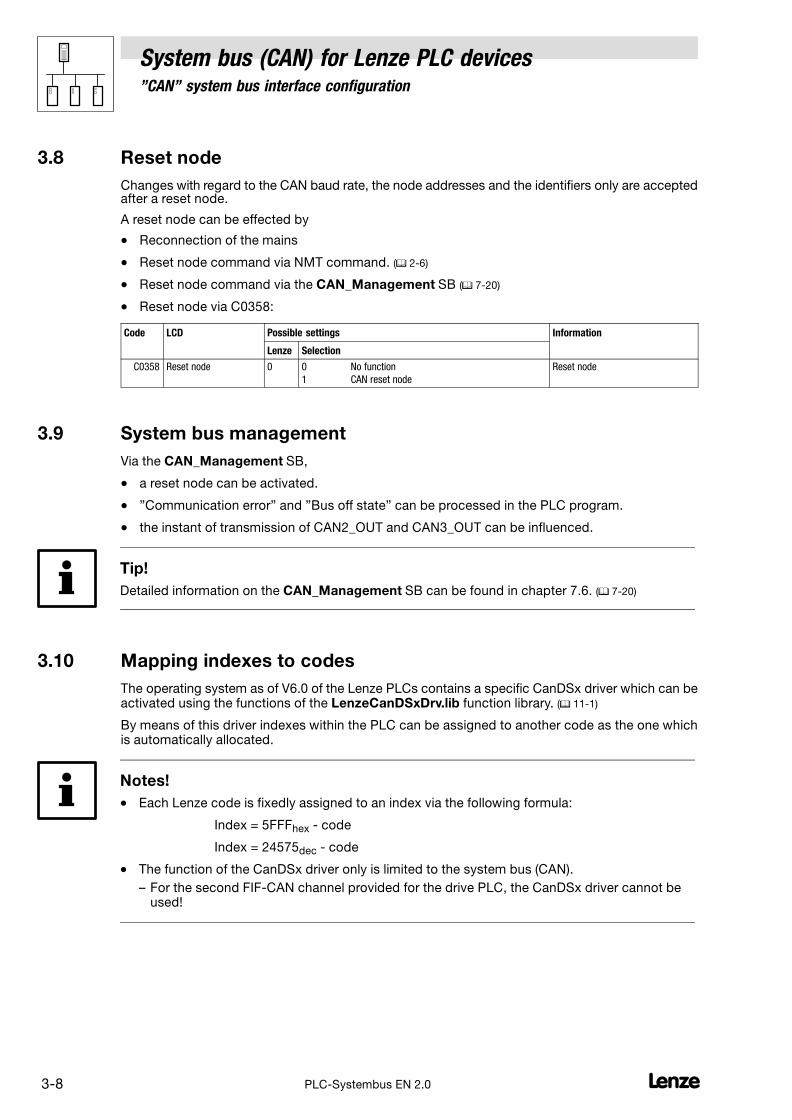
System bus (CAN) for Lenze PLC devices"CAN" system bus interface configuration
3−8 lPLC−Systembus EN 2.0
3.8 Reset node
Changes with regard to the CAN baud rate, the node addresses and the identifiers only are acceptedafter a reset node.
A reset node can be effected by
� Reconnection of the mains
� Reset node command via NMT command. (� 2−6)
� Reset node command via the CAN_Management SB (� 7−20)
� Reset node via C0358:
Code LCD Possible settings Information
Lenze Selection
C0358 Reset node 0 0 No function
1 CAN reset node
Reset node
3.9 System bus management
Via the CAN_Management SB,
� a reset node can be activated.
� "Communication error" and "Bus off state" can be processed in the PLC program.
� the instant of transmission of CAN2_OUT and CAN3_OUT can be influenced.
Tip!
Detailed information on the CAN_Management SB can be found in chapter 7.6. (� 7−20)
3.10 Mapping indexes to codes
The operating system as of V6.0 of the Lenze PLCs contains a specific CanDSx driver which can beactivated using the functions of the LenzeCanDSxDrv.lib function library. (� 11−1)
By means of this driver indexes within the PLC can be assigned to another code as the one whichis automatically allocated.
Notes!
� Each Lenze code is fixedly assigned to an index via the following formula:
Index = 5FFFhex − code
Index = 24575dec − code
� The function of the CanDSx driver only is limited to the system bus (CAN).
– For the second FIF−CAN channel provided for the drive PLC, the CanDSx driver cannot beused!

System bus (CAN) for Lenze PLC devices"CAN" system bus interface configuration
3−9l PLC−Systembus EN 2.0
3.10.1 Functional principle considering as example
Task
Within the PLC, a function has been realised from the user side, which can be parameterised via theuser code C3200/5. The index 21375dec is automatically assigned to code C3200:
Index = 24575dec − code = 24575dec − 3200 = 21375dec
On the basis of the communication profile used, this function, however, is to be parameterisable viathe index 4101dec/subindex 2 instead.
Solution
Via the functions of the LenzeCanDSxDrv.lib function library, index 4101dec/subindex 2 is simplydiverted to code C3200/5 within the PLC, so that the communication profile can be used unchanged.
Functional principle
The operating system (as of V6.0) of the Lenze PLCs contains a so−called "mapping table". With thistable up to 256 indexes within the PLC can be "mapped" to other codes than to those which areautomatically allocated.
If a CAN telegram arrives and the index is in the valid range, it is checked whether this index is listedin the mapping table.
� If the index is listed in the mapping table, the code which has been newly assigned to thisindex in the mapping table is accessed. �
� If the index is not listed in the mapping table, the code which is automatically allocated isaccessed, resulting from the above−mentioned formula. �
SDO telegram
Index numbervalid ?
CAN subindex
4101
yes
Index access: 4101/2
Code access: C3200/5
Mapping table
CAN index Lenze code Lenze subcode
2 3200 5
4101 1
20000 0
3200 4
3000 0
SDO telegram
Index numbervalid ?
CAN subindex
4101
yes
Index access: 21475/1
Lenze code = 24575 - Index = 24575 - 21475 = 3100Code access = C3100/1
Mapping table
CAN index Lenze code Lenze subcode
2 3200 5
4101 1
20000 0
3200 4
3000 0
� �
Fig. 3−2 Process of diverting indexes to codes
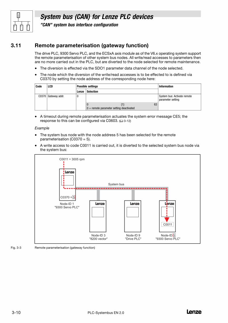
System bus (CAN) for Lenze PLC devices"CAN" system bus interface configuration
3−10 lPLC−Systembus EN 2.0
3.11 Remote parameterisation (gateway function)
The drive PLC, 9300 Servo PLC, and the ECSxA axis module as of the V6.x operating system supportthe remote parameterisation of other system bus nodes. All write/read accesses to parameters thenare no more carried out in the PLC, but are diverted to the node selected for remote maintenance.
� The diversion is effected via the SDO1 parameter data channel of the node selected.
� The node which the diversion of the write/read accesses is to be effected to is defined viaC0370 by setting the node address of the corresponding node here:
Code LCD Possible settings Information
Lenze Selection
C0370 Gateway addr. 0 System bus: Activate remoteparameter setting
0 {1} 63
0 = remote parameter setting deactivated
� A timeout during remote parameterisation actuates the system error message CE5; theresponse to this can be configured via C0603. (� 3−12)
Example
� The system bus node with the node address 5 has been selected for the remoteparameterisation (C0370 = 5).
� A write access to code C0011 is carried out, it is diverted to the selected system bus node viathe system bus:
L
Node-ID 1"9300 Servo PLC"
Node-ID 3"8200 vector"
Node-ID 9"Drive PLC"
L
Node-ID 5"9300 Servo PLC"
L L
C0370 = 5
C0011
C0011 = 3005 rpm
System bus
Fig. 3−3 Remote parameterisation (gateway function)
System bus (CAN) for Lenze PLC devices"CAN" system bus interface configuration
3−11l PLC−Systembus EN 2.0
3.12 Monitoring processes
3.12.1 Time monitoring for CAN1_IN ... CAN3_IN
For the inputs of the CAN1_IN ... CAN3_IN process data objects a time monitoring can be configuredvia C0357:
Code LCD Possible settings Information
Lenze Selection
C0357
1
2
3
CE1monit time
CE2monit time
CE3monit time
3000
3000
3000
0 {1 ms} 65000 Monitoring time for process datainput objects
The response for the case that no telegram has been received within the defined monitoring time canbe configured via codes C0591 ... C0593:
Code LCD Possible settings Information
Lenze Selection
C0591 MONIT CE1 3 0 TRIP
2 Warning
3 Off
Configuration of the monitoring forCAN1_IN error "CommErrCANIN1"(CAN1 CE1)
C0592 MONIT CE2 3 0 TRIP
2 Warning
3 Off
Configuration of the monitoring forCAN2_IN error "CommErrCANIN2"(CAN2 CE2)
C0593 MONIT CE3 3 0 TRIP
2 Warning
3 Off
Configuration of the monitoring forCAN3_IN error "CommErrCANIN3"(CAN3 CE3)
3.12.2 Bus−off
If the PLC has disconnected from the system bus due to too many incorrectly received telegrams,the signal "BusOffState" (CE4) is set.
The response to this can be configured via C0595:
Code LCD Possible settings Information
Lenze Selection
C0595 MONIT CE4 3 0 TRIP
2 Warning
3 Off
Configuration of the monitoring for
"BusOffState" (CE4)
Tip!
Possible causes for incorrectly received telegrams can be:
� Missing bus termination
� Non−sufficient shielding
� Differences in potential with regard to the earth connection of the control electronics
� Bus load too high

System bus (CAN) for Lenze PLC devices"CAN" system bus interface configuration
3−12 lPLC−Systembus EN 2.0
3.12.3 Time−out when remote parameterisation is activated
If a time−out occurs during the remote parameterisation (gateway function) activated via C0370, thesystem error message CE5 is output.
The response to this can be configured via C0603:
Code LCD Possible settings Information
Lenze Selection
C0603 MONIT CE5 3 System bus: Monitoringconfiguration
Time−out when remoteparameterisation is activated(C0370)
0 TRIP
2 Warning
3 Off
3.12.4 Response in the case of system bus fault messages
Overview of the system bus error sources registered by the PLC and of the possible settings for thecorresponding response:
Fault message Possible settings/response
Display ErrorNo.
Meaning TRIP Message Warning Fault/QSP
Off Code
CE1 62 CAN1_IN communication error
(time monitoring can be set via C0357/1)
− − • C0591
CE2 63 CAN2_IN communication error
(time monitoring can be set via C0357/2)
− − • C0592
CE3 64 CAN3_IN communication error
(time monitoring can be set via C0357/3)
− − • C0593
CE4 65 BUS−OFF state
(too many faulty telegrams were received)
− − • C0595
CE5 66 CAN time−out
(gateway function C0370)
− − • C0603
• Lenze setting
Possible
− Not possible
System bus (CAN) for Lenze PLC devices"CAN" system bus interface configuration
3−13l PLC−Systembus EN 2.0
3.13 Diagnostics
The following codes can be used for diagnostics purposes:
Code Information displayed Information
C0359 Operating status of the system bus Chapter 3.13.1 � 3−13
C0360 Number of the telegrams sent and received Chapter 3.13.2 � 3−14
C0361 Bus load (in %) Chapter 3.13.3 � 3−15
� Settings cannot be carried out via these codes.
3.13.1 Operating status of the CAN interface
Via C0359 you can have the operating status of the system bus displayed:
Code LCD Possible settings Information
Lenze Selection
C0359 CAN state � 0 Operational
1 Pre−operational
2 Warning
3 Bus off
System bus status
C0359 Operating status Information
0 Operational The system bus is fully functional. The PLC can transmit and receive parameter and process data.
1 Pre−operational The PLC can transmit and receive parameter data. Process data, however, are ignored.
A status change from Pre−operational to Operational can be effected by:
� the CAN master � 3−2
� a reset node
– via C0358, if the PLC has been configured as a "quasi" master. � 3−8
– via the binary input signal "reset node" at the CAN_Management SB � 7−20
2 Warning The PLC has received faulty telegrams and is only involved in the system bus passively, i. e. no data can besent from the PLC anymore.
Possible causes:
� Missing bus termination
� Non−sufficient shielding
� Differences in potential with regard to the earth connection of the control electronics
� Bus load too high
� PLC is not connected to the system bus.
3 Bus−off The PLC has disconnected from the system bus due to too many faultily received telegrams.
� The response to this status can be configured via C0595. � 3−11
System bus (CAN) for Lenze PLC devices"CAN" system bus interface configuration
3−14 lPLC−Systembus EN 2.0
3.13.2 Telegram counter
Via C0360 you can have the number of the telegrams sent and received by the PLC viaCAN1_IO ... CAN3_IO displayed.
� Only the telegrams which are valid for the PLC are counted.
� Each transmit and receive channel is evaluated separately.
� The max. counter content is 65535 (16 bit); if this value is exceeded, the correspondingcounter starts with 0 again.
Code LCD Possible settings Information
Lenze Selection
C0360 CAN message � 0 {1} 65535 System bus telegram counter
(number of telegrams)
� For values > 65535 countingrestarts with 0.
1 Message OUT All sent
2 Message IN All received
3 Message OUT1 Sent on CAN_OUT1
4 Message OUT2 Sent on CAN_OUT2
5 Message OUT3 Sent on CAN_OUT3
6 Message POUT1 Sent on parameter data channel 1
7 Message POUT2 Sent on parameter data channel 2
8 Message IN1 Received from CAN_IN1
9 Message IN2 Received from CAN_IN2
10 Message IN3 Received from CAN_IN3
11 Message PIN1 Received from parameter datachannel 1
12 Message PIN2 Received from parameter datachannel 2

System bus (CAN) for Lenze PLC devices"CAN" system bus interface configuration
3−15l PLC−Systembus EN 2.0
3.13.3 Bus load by the PLC
Via C0361 you can receive a percentage display of the extent to which the system bus is loaded bythe telegrams of the PLC.
� Only valid telegrams are considered.
� Each transmit and receive channel is evaluated separately.
Code LCD Possible settings Information
Lenze Selection
C0361 Load IN/OUT � 0 {1 %} 100 System bus − bus load
� Trouble−free operation demandsthat the total bus load (allconnected devices) does notexceed 80 %.
1 Load OUT All sent
2 Load IN All received
3 Load OUT1 Sent on CAN_OUT1
4 Load OUT2 Sent on CAN_OUT2
5 Load OUT3 Sent on CAN_OUT3
6 Load POUT1 Sent on parameter data channel 1
7 Load POUT2 Sent on parameter data channel 2
8 Load IN1 Received from CAN_IN1
9 Load IN2 Received from CAN_IN2
10 Load IN3 Received from CAN_IN3
11 Load PIN1 Received from parameter datachannel 1
12 Load PIN2 Received from parameter datachannel 2
Limits of the data transmission
Data transmission is limited by the number of telegrams per time unit and by the data transmissionspeed.
� For a data exchange within a drive system only consisting of Lenze controllers/PLCs, theselimits can be determined by adding code C0361/1 of all devices involved.
� Example: Three controllers are connected to each other via the system bus:
Value of C0361/1 on controller 1: 23.5 % bus load
Value of C0361/1 on controller 2: 12.6 % bus load
Value of C0361/1 on controller 3: 16.0 % bus load
52.1 % total bus load
Tip!
� The bus load of all devices involved should not exceed 80 %.
� If other devices, like for example decentralised inputs and outputs are connected, thesetelegrams are to be considered also.
� A bus overload for instance can be effected by an event−controlled transmission of continuallychanging signals.
– Remedy: Accordingly alter the setting of the cycle time for CAN2_OUT or CAN3_OUT, sothat the total of all bus loads does not exceed the value of 80 %. (� 3−6)

System bus (CAN) for Lenze PLC devices"CAN" system bus interface configuration
3−16 lPLC−Systembus EN 2.0

System bus (CAN) for Lenze PLC devicesConfiguration (AIF interface)
4−1l PLC−Systembus EN 2.0
4 Configuration (AIF interface)
By means of an according fieldbus module (e. g. 2175) you can use the AIF interface of the 9300Servo PLC, drive PLC and of the ECSxA axis module as an additional system bus interface.
Note!
If the fieldbus module attached to the AIF interface and the integrated system bus interface areconnected to the same system bus network, please be absolutely sure that different CANaddresses as well as different identifiers have been set for the interfaces!
Tip!
Changes with regard to the CAN baud rate, the CAN addresses, and the identifiers for PDOs onlyare accepted after a reset node.
A reset node can be effected by
� Reconnection of the mains
� Reset node command via NMT command (� 2−6)
� Reset node via C0358 (� 3−8)
4.1 CAN baud rate
In order to accomplish communication via the system bus, all nodes have to use the same baud ratefor data transmission.
� The configuration of the baud rate is effected via code C2351:
Code LCD Possible settings Information
Lenze Selection
C2351 XCAN baud rate 0 0 500 kbit/s
1 250 kbit/s
2 125 kbit/s
3 50 kbit/s
4 1000 kbit/s
5 20 kbit/s (not for ECSxA!)
6 10 kbit/s (not for ECSxA!)
System bus − baud rate
� Save changes with C0003 = 1.
� Changes are only valid afterreset node!

System bus (CAN) for Lenze PLC devicesConfiguration (AIF interface)
4−2 lPLC−Systembus EN 2.0
4.2 CAN boot−up
If the initialisation of the system bus and the associated state change of Pre−operational toOperational is not taken over by a higher−level master system, the PLC or a controller can bedesignated as a "quasi" master to accomplish this task.
� The configuration is effected via code C2352:
Code LCD Possible settings Information
Lenze Selection
C2352 XCAN mst 0 0 Boot−up not active
1 Boot−up active
Device sends system bus boot−upand thus is the "quasi" master.
Delay time for system bus initialisation (boot−up)
Some nodes (e. g. HMIs) require a specific starting time after mains connection before they can betransferred to the Operational state via NMT commands by the master.
In order to ensure that even the node with the greatest starting time really is ready to receive NMTcommands, you can set a delay time. When it has expired, NMT commands can only be transmittedafter mains power−up.
� The configuration of this delay time is effected via code C2356/1:
Code LCD Possible settings Information
Lenze Selection
C2356/1 XCAN boot−up 3000 0 {1 ms} 65000 Delay time after power−on forinitialisation via the "quasi" master
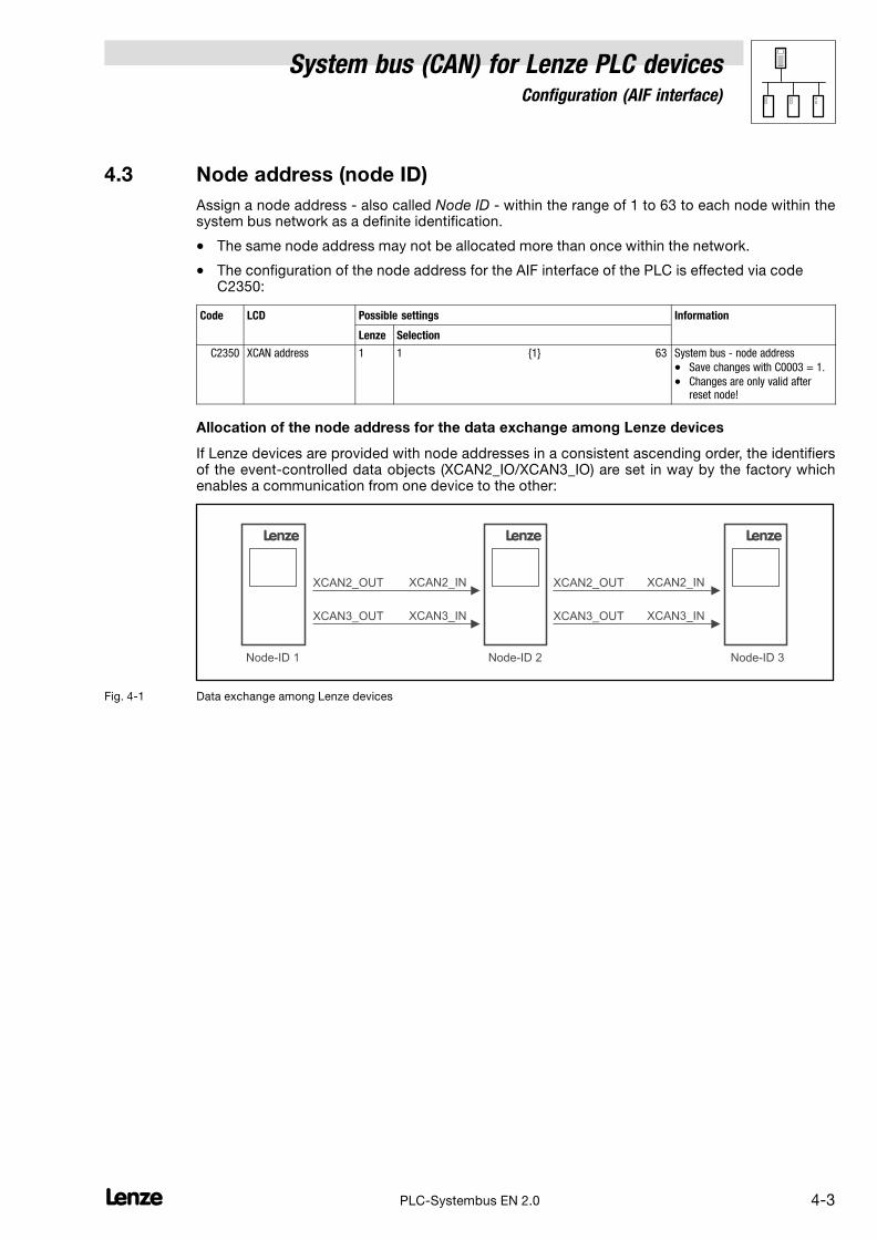
System bus (CAN) for Lenze PLC devicesConfiguration (AIF interface)
4−3l PLC−Systembus EN 2.0
4.3 Node address (node ID)
Assign a node address − also called Node ID − within the range of 1 to 63 to each node within thesystem bus network as a definite identification.
� The same node address may not be allocated more than once within the network.
� The configuration of the node address for the AIF interface of the PLC is effected via codeC2350:
Code LCD Possible settings Information
Lenze Selection
C2350 XCAN address 1 1 {1} 63 System bus − node address
� Save changes with C0003 = 1.
� Changes are only valid afterreset node!
Allocation of the node address for the data exchange among Lenze devices
If Lenze devices are provided with node addresses in a consistent ascending order, the identifiersof the event−controlled data objects (XCAN2_IO/XCAN3_IO) are set in way by the factory whichenables a communication from one device to the other:
L
Node-ID 1
XCAN2_OUT XCAN2_IN
XCAN3_OUT XCAN3_IN
L
Node-ID 2
XCAN2_OUT XCAN2_IN
XCAN3_OUT XCAN3_IN
L
Node-ID 3
Fig. 4−1 Data exchange among Lenze devices

System bus (CAN) for Lenze PLC devicesConfiguration (AIF interface)
4−4 lPLC−Systembus EN 2.0
4.4 Identifiers of the process data objects
The identifiers for the XCAN1_IO ... XCAN3_IO process data objects are generated by the so−calledbasic identifier and the node address set in C2350:
Identifier � basic identifier � node address
Basic identifiers
dec hex
PDOs XCAN1_IO (cyclic process data)
XCAN1_IN 512 200
XCAN1_OUT 384 180
XCAN2_IO (event− or time−controlled process data)
XCAN2_IN 640 280
XCAN2_OUT 641 281
XCAN3_IO (event− or time−controlled process data)
XCAN3_IN 768 300
XCAN3_OUT 769 301
4.4.1 Allocation of individual identifiers
For greater system bus networks with many nodes it can be reasonable to set individual identifiersfor the XCAN1_IO ... XCAN3_IO process data objects via C2353/C2354, which are independent ofthe node address set in C2350:
1. Set C2353/x to "1".
– (x = subcode of the corresponding process data object):
Code LCD Possible settings Information
Lenze Selection
C2353 XCAN addr sel 0 Identifier assignment via C2350 + basicidentifier
1 Identifier assignment via C2354/x
Source for the identifiers of theprocess data objects
� Save changes with C0003 = 1.
� Changes are only valid afterreset node!
1 XCAN addr sel1 0 XCAN1_IN/OUT
2 XCAN addr sel2 0 XCAN2_IN/OUT
3 XCAN addr sel3 0 XCAN3_IN/OUT
2. Set the value which added to "384" makes the desired identifier in C2354/x.
– (x = subcode of the corresponding process data object):
Code LCD Possible settings Information
Lenze Selection
C2354 XCAN addr 0 {1} 1663 Specification of individualidentifiers for the process dataobjects
1
2
3
4
5
6
IN1 addr2
OUT1 addr2
IN2 addr2
OUT2 addr2
IN3 addr2
OUT3 addr2
129
1
257
258
385
386
XCAN1_IN
XCAN1_OUT
XCAN2_IN
XCAN2_OUT
XCAN3_IN
XCAN3_OUT
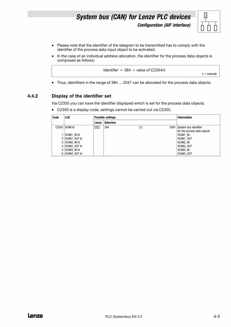
System bus (CAN) for Lenze PLC devicesConfiguration (AIF interface)
4−5l PLC−Systembus EN 2.0
� Please note that the identifier of the telegram to be transmitted has to comply with theidentifier of the process data input object to be activated.
� In the case of an individual address allocation, the identifier for the process data objects iscomposed as follows:
Identifier � 384 � value of C2354/xx = subcode
� Thus, identifiers in the range of 384 ... 2047 can be allocated for the process data objects.
4.4.2 Display of the identifier set
Via C2355 you can have the identifier displayed which is set for the process data objects.
� C2355 is a display code, settings cannot be carried out via C2355.
Code LCD Possible settings Information
Lenze Selection
C2355
1
2
3
4
5
6
XCAN Id
XCAN1_IN Id
XCAN1_OUT Id
XCAN2_IN Id
XCAN2_OUT Id
XCAN3_IN Id
XCAN3_OUT Id
� 384 {1} 2047 System bus identifier
for the process data objects
XCAN1_IN
XCAN1_OUT
XCAN2_IN
XCAN2_OUT
XCAN3_IN
XCAN3_OUT

System bus (CAN) for Lenze PLC devicesConfiguration (AIF interface)
4−6 lPLC−Systembus EN 2.0
4.5 Cycle time (XCAN1_OUT ... XCAN3_OUT)
The transmission of the output data of XCAN1_OUT ... XCAN3_OUT can be carried out in anevent−controlled or time−controlled manner.
� The configuration of the transmission mode is effected via code C2356/x:
Code LCD Possible settings Information
Lenze Selection
C2356
2
3
4
XCAN1_OUT T
XCAN2_OUT T
XCAN3_OUT T
0
0
0 {1 ms} 65000
0 = event−controlled transmission
Cycle time for transmitting theprocess data object
Event−controlled transmission
C2356/x = 0
� The transmission of the output data is always effected if a value has changed within the8 bytes of user data (Lenze setting).
Time−controlled transmission
C2356/x = 1 ... 65000
� The transmission of the output data is effected within the cycle time set in C2356/x (relating tothe task cycle time).
Example:
� The CAN object is used in a 10 ms task.
� Factor set via C2356/2 = 5
The CAN object is transmitted after every fifth cycle of the task, i. e. every 50 ms (10 ms x 5).

System bus (CAN) for Lenze PLC devicesConfiguration (AIF interface)
4−7l PLC−Systembus EN 2.0
4.6 Synchronisation
Tip!
By means of the CAN_Synchronization SB the internal time base of the PLC can be synchronisedwith the arrival of the sync telegram.
Thus, the internal calculating processes (e. g. control−oriented processes) of the PLC can besynchronised with the calculating processes of other nodes which can also process the synctelegram.
Detailed information on the CAN_Synchronization SB can be found in chapter 7.7. (� 7−23)
4.6.1 XCAN sync response
The response to the reception of a sync telegram can be configured via C2375:
Code LCD Possible settings IMPORTANT
Lenze Selection
C2375 XCAN Tx mode AIF−CAN sync response
� Selection of cycle time underC2356
0 Sync with response
1 Sync without response
2 Event−controlled (with mask)/cyclically
3 Event−controlled (with mask)with cyclic overlay
1 0 XCAN1_OUT
2 0 XCAN2_OUT
3 0 XCAN3_OUT
4.6.2 XCAN sync identifier
The transmission or reception identifiers of the sync telegram can be configured via C2367/C2368:
Code LCD Possible settings IMPORTANT
Lenze Selection
C2367 Sync Rx Id 128 1 {1} 256 XCAN sync Rx identifier
Receive identifier for the synctelegram
C2368 Sync Tx Id 128 1 {1} 256 XCAN sync Tx identifier
Transmit identifier for the synctelegram
4.6.3 XCAN sync Tx transmission cycle
The cycle time within which a sync telegram with the identifier set in C2368 is transmitted can beconfigured via C2356/5:
Code LCD Possible settings IMPORTANT
Lenze Selection
C2356
5
Sync Tx time
0
0 {1 ms} 65535
0 = Off XCAN sync time
Sync transmission telegram cycle
System bus (CAN) for Lenze PLC devicesConfiguration (AIF interface)
4−8 lPLC−Systembus EN 2.0
4.7 Reset node
Changes with regard to the CAN baud rate, the node addresses, and the identifiers only are acceptedafter a reset node.
A reset node can be effected by
� Reconnection of the mains
� Reset node command via NMT command. (� 2−6)
� Reset node command via the CAN_Management SB (� 7−20)
� Reset node via C0358:
Code LCD Possible settings Information
Lenze Selection
C0358 Reset node 0 0 No function
1 CAN reset node
Reset node
4.8 Monitoring processes
4.8.1 Time monitoring for XCAN1_IN ... XCAN3_IN
For the inputs of the XCAN1_IN ... XCAN3_IN process data objects a time monitoring can beconfigured via C2357:
Code LCD Possible settings Information
Lenze Selection
C2357 CE monit time 0 {1 ms} 65000 Monitoring time for XCAN processdata input objects
1 3000 XCAN1_IN
2 3000 XCAN2_IN
3 3000 XCAN3_IN
4 1 Bus−off
The response for the case that no telegram has been received within the defined monitoring time canbe configured via code C2382/x:
Code LCD Possible settings Information
Lenze Selection
C2382 XCAN Conf. CE
0
0 Off
1 Controller inhibit
2 Quick stop (QSP)
Configuration of XCAN monitoring
"BusOffState"
� Controller inhibit or quick stop(QSP) can only be carried out for9300 Servo PLC and ECSxA!
1 0 XCAN1_IN
2 0 XCAN2_IN
3 0 XCAN3_IN
4 0 Bus−off
5 0 Live guarding event

System bus (CAN) for Lenze PLC devicesConfiguration (AIF interface)
4−9l PLC−Systembus EN 2.0
4.8.2 Bus off
If the PLC has disconnected from the system bus due to too many incorrectly received telegrams,the signal "BusOffState" (CE14) is set.
The response to this can be configured via C2382/4:
Code LCD Possible settings Information
Lenze Selection
C2382
4
XCAN Conf. CE
0
0 Off
1 Controller inhibit
2 Quick stop (QSP)
Configuration of XCAN monitoring
"BusOffState"
� Controller inhibit or quick stop(QSP) can only be carried out for9300 Servo PLC and ECSxA!
Tip!
Possible causes for incorrectly received telegrams can be:
� Missing bus termination
� Non−sufficient shielding
� Differences in potential with regard to the earth connection of the control electronics
� Bus load too high. See chapter 3.13.3, "Bus load by the PLC". (� 3−15)
4.8.3 Response for system bus fault messages
Overview of the system bus error sources registered by the PLC and of the possible settings for thecorresponding response:
Fault message Possible settings/response
Display Error No. Meaning CINH Fault/QSP Off Code
XCAN Conf. CE 1) XCAN1_IN communication error
(time monitoring can be set via C2357/1)
© C2382/1
XCAN Conf. CE 1) XCAN2_IN communication error
(time monitoring can be set via C2357/2)
• C2382/2
XCAN Conf. CE 1) XCAN3_INcommunication error
(time monitoring can be set via C2357/3)
• C2382/3
XCAN Conf. CE 1) BUS−OFF state
(too many faulty telegrams were received)
• C2382/4
1) Not available; status can be determined via C2121. � 4−10 • Lenze setting
Possible

System bus (CAN) for Lenze PLC devicesConfiguration (AIF interface)
4−10 lPLC−Systembus EN 2.0
4.9 Diagnostics
The following codes can be used for diagnostics purposes:
Code Information displayed Information
C2121 AIF−CAN operating status Chapter 4.9.1 � 4−10
� Settings cannot be carried out via these codes.
4.9.1 Automation interface (AIF) operating status
Via C2121 you can have the operating status of the automation interface displayed:
Code LCD Possible settings Information
Lenze Selection
C2121 AIF state � Bit 0 XCAN1_IN monitoring time
Bit 1 XCAN2_IN monitoring time
Bit 2 XCAN3_IN monitoring time
Bit 3 XCAN bus−off
Bit 4 XCAN operational
Bit 5 XCAN pre−operational
Bit 6 XCAN warning
Bit 7 Internally assigned
AIF status, bit−coded
� Detailed information on this canbe found in the description forthe corresponding fieldbusmodule.
C2121 Operating status Information
Bit4 = 1 Operational The system bus is fully functional. The PLC can transmit and receive parameter and process data.
Bit5 = 1 Pre−operational The PLC can transmit and receive parameter data. Process data, however, are ignored.
A status change from Pre−Operational to Operational can be effected by:
� the CAN master � 4−2
� a reset node
– via C0358, if the PLC has been configured as a "quasi" master. � 3−8
– via the binary input signal "Reset node" at the CAN_Management SB � 7−20
Bit6 = 1 Warning The PLC has received faulty telegrams and is only involved in the system bus passively, i. e. no data can besent from the PLC anymore.
Possible causes:
� Missing bus termination
� Non−sufficient shielding
� Differences in potential with regard to the earth connection of the control electronics
� Bus load too high
� PLC is not connected to the system bus.
Bit3 = 1 Bus−off The PLC has disconnected from the system bus due to too many faultily received telegrams.
� The response to this status can be configured via C2382/4. � 4−9
System bus (CAN) for Lenze PLC devicesConfiguration (FIF interface)
5−1l PLC−Systembus EN 2.0
5 Configuration (FIF interface)
By means of an appropriate function module (e. g. CAN−I/O system bus) you can use the FIF interfaceof the Drive PLC as an additional system bus interface.
Note!
If the fieldbus module attached to the FIF interface and the integrated system bus interface areconnected to the same system bus network, please be absolutely sure that different CANaddresses as well as different identifiers have been set for the interfaces!
Tip!
Changes with regard to the CAN baud rate, the CAN addresses, and the identifiers for PDOs onlyare accepted after a reset node.
A reset node can be effected by
� Reconnection of the mains
� Reset node command via NMT command. (� 2−6)
� Reset node via C0358 (� 5−8)
5.1 CAN baud rate
In order to accomplish communication via the system bus, all nodes have to use the same baud ratefor data transmission.
� The configuration of the baud rate is effected via code C2451:
Code LCD Possible settings Information
Lenze Selection
C2451 CAN1 baud rate 0 0 500 kbit/s
1 250 kbit/s
2 125 kbit/s
3 50 kbit/s
4 1000 kbit/s
System bus − baud rate
� Save changes with C0003 = 1.
� Changes are only valid afterreset node!

System bus (CAN) for Lenze PLC devicesConfiguration (FIF interface)
5−2 lPLC−Systembus EN 2.0
5.2 CAN boot−up
If the initialisation of the system bus and the associated state change from Pre−operational toOperational is not taken over by a higher−level master system, the PLC or a controller can bedesignated as a "quasi" master to accomplish this task.
� The configuration is effected via code C2452:
Code LCD Possible settings Information
Lenze Selection
C2452 CAN1 mst 0 0 Boot−up not active
1 Boot−up active
Device sends system bus boot−upand thus is the "quasi" master.
Delay time for system bus initialisation (boot−up)
Some nodes (e. g. HMIs) require a specific starting time after mains connection before they can betransferred to the Operational state via NMT commands by the master.
In order to ensure that even the node with the greatest starting time really is ready to receive NMTcommands, you can set a delay time. When it has expired, NMT commands can only be transmittedafter mains power−up.
� The configuration of this delay time is effected via code C2456/1:
Code LCD Possible settings Information
Lenze Selection
C2456
1
CAN1 boot−up
3000
0 {1 ms} 65000 Delay time after power−on forinitialisation via the "quasi" master

System bus (CAN) for Lenze PLC devicesConfiguration (FIF interface)
5−3l PLC−Systembus EN 2.0
5.3 Node address (node ID)
Assign a node address − also called Node ID − within the range of 1 to 63 to each node within thesystem bus network as a definite identification.
� The same node address may not be assigned more than once within the network.
� The configuration of the node address for the FIF interface of the PLC is effected via codeC2450:
Code LCD Possible settings Information
Lenze Selection
C2450 CAN1 address 1 1 {1} 63 System bus node address
� Save modifications with C0003= 1.
� Modifications are only validafter reset node!
Allocation of the node address for the data exchange among Lenze devices
If Lenze devices are provided with node addresses in a consistent ascending order, the identifiersof the event−controlled data objects (FIF_CAN2_IO/FIF_CAN3_IO) are set in way by the factory whichenables a communication from one device to the other:
L
Node-ID 1
FIF-CAN2_OUT
FIF-CAN2_INFIF-CAN3_OUT
FIF-CAN3_IN
L
Node-ID 2
FIF-CAN2_OUT
FIF-CAN2_INFIF-CAN3_OUT
FIF-CAN3_IN
L
Node-ID 3
Fig. 5−1 Data exchange among Lenze devices
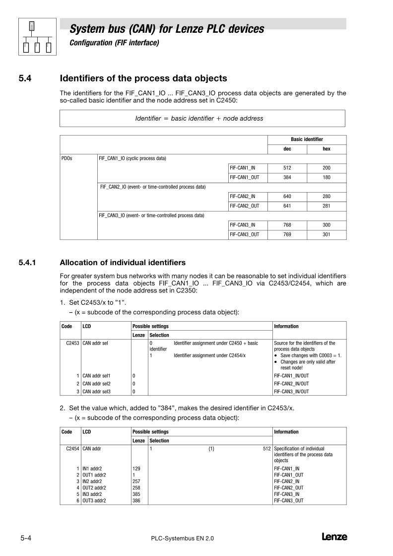
System bus (CAN) for Lenze PLC devicesConfiguration (FIF interface)
5−4 lPLC−Systembus EN 2.0
5.4 Identifiers of the process data objects
The identifiers for the FIF_CAN1_IO ... FIF_CAN3_IO process data objects are generated by theso−called basic identifier and the node address set in C2450:
Identifier � basic identifier � node address
Basic identifier
dec hex
PDOs FIF_CAN1_IO (cyclic process data)
FIF−CAN1_IN 512 200
FIF−CAN1_OUT 384 180
FIF_CAN2_IO (event− or time−controlled process data)
FIF−CAN2_IN 640 280
FIF−CAN2_OUT 641 281
FIF_CAN3_IO (event− or time−controlled process data)
FIF−CAN3_IN 768 300
FIF−CAN3_OUT 769 301
5.4.1 Allocation of individual identifiers
For greater system bus networks with many nodes it can be reasonable to set individual identifiersfor the process data objects FIF_CAN1_IO ... FIF_CAN3_IO via C2453/C2454, which areindependent of the node address set in C2350:
1. Set C2453/x to "1".
– (x = subcode of the corresponding process data object):
Code LCD Possible settings Information
Lenze Selection
C2453 CAN addr sel 0 Identifier assignment under C2450 + basicidentifier
1 Identifier assignment under C2454/x
Source for the identifiers of theprocess data objects
� Save changes with C0003 = 1.
� Changes are only valid afterreset node!
1 CAN addr sel1 0 FIF−CAN1_IN/OUT
2 CAN addr sel2 0 FIF−CAN2_IN/OUT
3 CAN addr sel3 0 FIF−CAN3_IN/OUT
2. Set the value which, added to "384", makes the desired identifier in C2453/x.
– (x = subcode of the corresponding process data object):
Code LCD Possible settings Information
Lenze Selection
C2454 CAN addr 1 {1} 512 Specification of individualidentifiers of the process dataobjects
1
2
3
4
5
6
IN1 addr2
OUT1 addr2
IN2 addr2
OUT2 addr2
IN3 addr2
OUT3 addr2
129
1
257
258
385
386
FIF−CAN1_IN
FIF−CAN1_OUT
FIF−CAN2_IN
FIF−CAN2_OUT
FIF−CAN3_IN
FIF−CAN3_OUT

System bus (CAN) for Lenze PLC devicesConfiguration (FIF interface)
5−5l PLC−Systembus EN 2.0
� Please note that the identifier of the telegram to be transmitted has to comply with theidentifier of the process data input object to be activated.
� In the case of an individual address allocation, the identifier for the process data objects iscomposed as follows:
Identifier � 384 � value of C2454/xx = subcode
� Thus, for the process data objects identifiers in the range of 385 ... 896 can be allocated.
5.4.2 Display of the identifiers set
Via C2455 you can have the identifier displayed which is set for the process data objects.
� C2455 is a display code, settings cannot be carried out via C2455.
Code LCD Possible settings Information
Lenze Selection
C2455
1
2
3
4
5
6
CAN Id
CAN1_IN Id
CAN1_OUT Id
CAN2_IN Id
CAN2_OUT Id
CAN3_IN Id
CAN3_OUT Id
� 385 {1} 896 System bus identifier
for the process data objects
FIF−CAN1_IN
FIF−CAN1_OUT
FIF−CAN2_IN
FIF−CAN2_OUT
FIF−CAN3_IN
FIF−CAN3_OUT

System bus (CAN) for Lenze PLC devicesConfiguration (FIF interface)
5−6 lPLC−Systembus EN 2.0
5.5 Cycle time (FIF_CAN2_OUT/FIF_CAN3_OUT)
The transmission of the output data of FIF−CAN2_OUT and FIF−CAN3_OUT can be carried out in anevent−controlled or time−controlled manner.
� The configuration of the transmission mode is effected via code C2456/x:
Code LCD Possible settings Information
Lenze Selection
C2456 0 {1} 65000
0 = event−controlled transmission
Factor to the task time fortransmitting the process dataobject
2
3
CAN2_OUT T
CAN3_OUT T
0
0
FIF−CAN2_OUT
FIF−CAN3_OUT
Event−controlled transmission
C2456/x = 0
� The transmission of the output data is always effected if a value has changed within the8 bytes of user data (Lenze setting).
Time−controlled transmission
C2456/x = 1 ... 65000
� The transmission of the output data is effected within the cycle time set in C2456/x (relating tothe task cycle time).
Example:
� The CAN object is used in a 10 ms task.
� Factor set via C2456/2 = 5
The CAN object is transmitted after every fifth cycle of the task, i. e. every 50 ms (10 ms x 5).
5.6 Delay time (FIF_CAN2_OUT/FIF_CAN3_OUT)
For the transmission of the output data of FIF−CAN2_OUT and FIF−CAN3_OUT a delay time can beconfigured via code C2456/4:
Code LCD Possible settings Information
Lenze Selection
C2456
4 CAN delay 20
0 {1 ms} 65000 Delay time for sending the processdata object
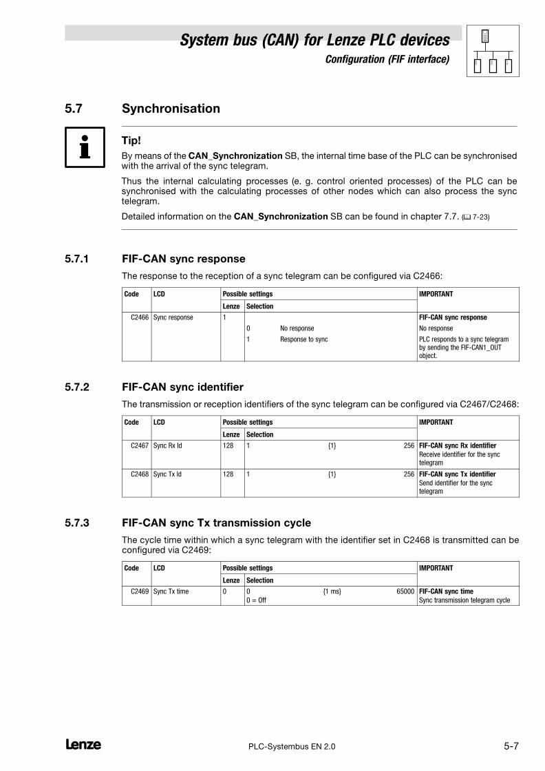
System bus (CAN) for Lenze PLC devicesConfiguration (FIF interface)
5−7l PLC−Systembus EN 2.0
5.7 Synchronisation
Tip!
By means of the CAN_Synchronization SB, the internal time base of the PLC can be synchronisedwith the arrival of the sync telegram.
Thus the internal calculating processes (e. g. control oriented processes) of the PLC can besynchronised with the calculating processes of other nodes which can also process the synctelegram.
Detailed information on the CAN_Synchronization SB can be found in chapter 7.7. (� 7−23)
5.7.1 FIF−CAN sync response
The response to the reception of a sync telegram can be configured via C2466:
Code LCD Possible settings IMPORTANT
Lenze Selection
C2466 Sync response 1 FIF−CAN sync response
0 No response No response
1 Response to sync PLC responds to a sync telegramby sending the FIF−CAN1_OUTobject.
5.7.2 FIF−CAN sync identifier
The transmission or reception identifiers of the sync telegram can be configured via C2467/C2468:
Code LCD Possible settings IMPORTANT
Lenze Selection
C2467 Sync Rx Id 128 1 {1} 256 FIF−CAN sync Rx identifier
Receive identifier for the synctelegram
C2468 Sync Tx Id 128 1 {1} 256 FIF−CAN sync Tx identifier
Send identifier for the synctelegram
5.7.3 FIF−CAN sync Tx transmission cycle
The cycle time within which a sync telegram with the identifier set in C2468 is transmitted can beconfigured via C2469:
Code LCD Possible settings IMPORTANT
Lenze Selection
C2469 Sync Tx time 0 0 {1 ms} 65000
0 = Off
FIF−CAN sync time
Sync transmission telegram cycle

System bus (CAN) for Lenze PLC devicesConfiguration (FIF interface)
5−8 lPLC−Systembus EN 2.0
5.8 Reset node
Changes with regard to the CAN baud rate, the node addresses, and the identifiers only are acceptedafter a reset node.
A reset node can be effected by
� Reconnection of the mains
� Reset node command via NMT command. (� 2−6)
� Reset node command via the FIF_CAN_Management SB (� 8−4)
� Reset node via C2458:
Code LCD Possible settings Information
Lenze Selection
C2458 Reset node 0 0 No function
1 FIF−CAN reset node
FIF−CAN reset node
5.9 System bus management
Via the FIF_CAN_Management SB,
� a reset node can be activated.
� "Communication error" and "Bus off state" can be processed in the PLC program.
� the instant of transmission of FIF−CAN2_OUT and FIF−CAN3_OUT can be influenced.
Tip!
Detailed information on the FIF_CAN_Management SB can be found in chapter 8.4. (� 8−4)

System bus (CAN) for Lenze PLC devicesConfiguration (FIF interface)
5−9l PLC−Systembus EN 2.0
5.10 Monitoring processes
5.10.1 Time monitoring for FIF−CAN1_IN ... FIF−CAN3_IN
For the inputs of the process data objects FIF−CAN1_IN ... FIF−CAN3_IN a time monitoring can beconfigured via C2457:
Code LCD Possible settings Information
Lenze Selection
C2457
1
2
3
CE11monit time
CE12monit time
CE13monit time
3000
3000
3000
0 {1 ms} 65000 Monitoring time for process datainput objects
The response for the case that no telegram has been received within the defined monitoring time canbe configured via codes C2481 ... C2483:
Code LCD Possible settings Information
Lenze Selection
C2481 MONIT CE11 3 0 TRIP
2 Warning
3 Off
Configuration of the monitoring for
FIF−CAN1_IN error (CE11)
C2482 MONIT CE12 3 0 TRIP
2 Warning
3 Off
Configuration of the monitoring for
FIF−CAN2_IN error (CE12)
C2483 MONIT CE13 3 0 TRIP
2 Warning
3 Off
Configuration of the monitoring for
FIF−CAN3_IN error (CE13)
5.10.2 Bus−off
If the PLC has disconnected from the system bus due to too many incorrectly received telegrams,the signal "BusOffState" (CE14) is set.
The response to this can be configured via C2484:
Code LCD Possible settings Information
Lenze Selection
C2484 MONIT CE14 0 0 Off
1 Controller inhibit
2 Quick stop (QSP)
Configuration of the monitoring for
"BusOffState" (CE14)
Tip!
Possible causes for incorrectly received telegrams can be:
� Missing bus termination
� Non−sufficient shielding
� Differences in potential with regard to the earth connection of the control electronics
� Bus load too high. See chapter 3.13.3, "Bus load by the PLC". (� 3−15)

System bus (CAN) for Lenze PLC devicesConfiguration (FIF interface)
5−10 lPLC−Systembus EN 2.0
5.10.3 Response in the case of system bus fault messages
Overview of the system bus error sources registered by the PLC as well as of the possible settingsfor the corresponding response:
Fault message Possible settings/response
Display ErrorNo.
Meaning TRIP Message Warning Fault/QSP
Off Code
CE11 122 Communication error FIF−CAN1_IN
(Time monitoring can be set via C2457/1)
− − • C2481
CE12 123 Communication error FIF−CAN2_IN
(Time monitoring can be set via C2457/2)
− − • C2482
CE13 124 Communication error FIF−CAN3_IN
(Time monitoring can be set via C2457/3)
− − • C2483
CE14 125 BUS−OFF state
(too many faulty telegrams were received)
− − • C2484
• Lenze setting
Possible
− Not possible
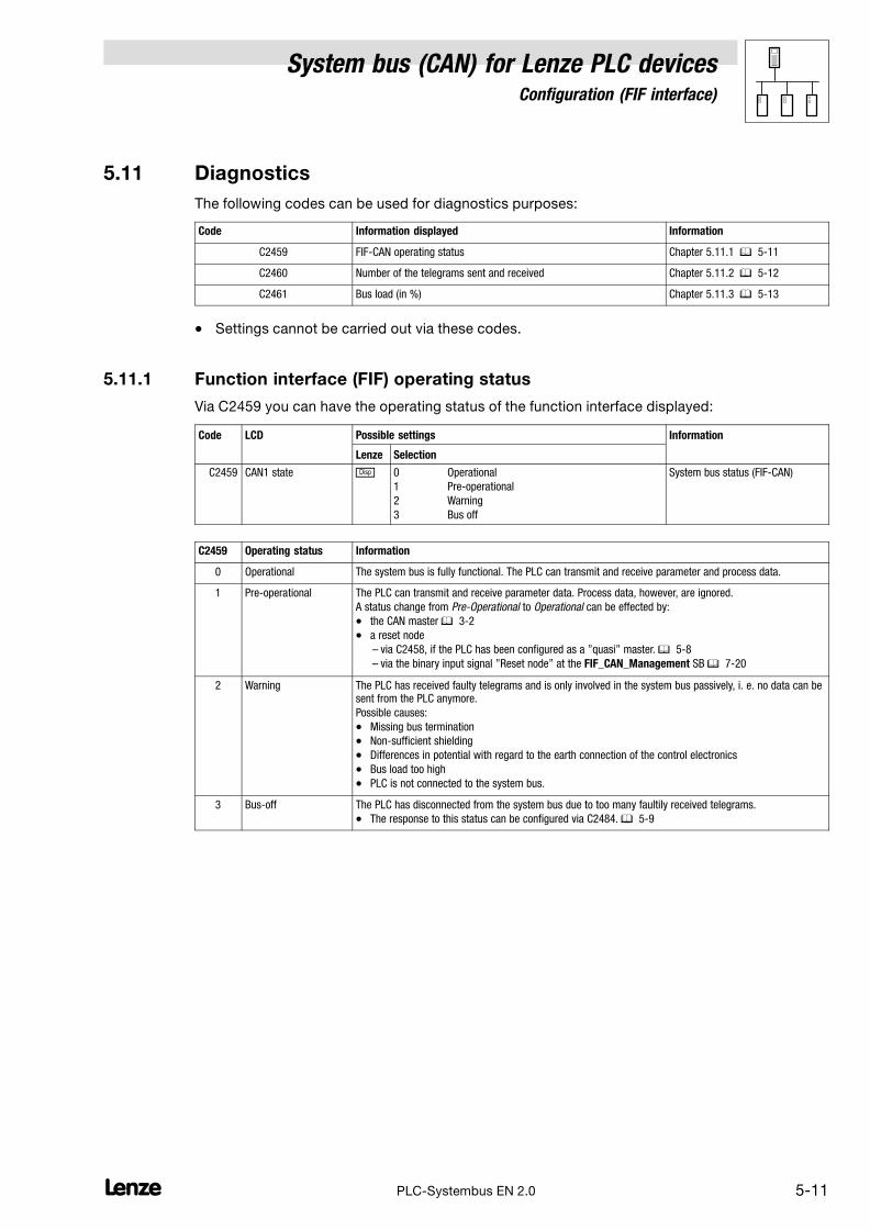
System bus (CAN) for Lenze PLC devicesConfiguration (FIF interface)
5−11l PLC−Systembus EN 2.0
5.11 Diagnostics
The following codes can be used for diagnostics purposes:
Code Information displayed Information
C2459 FIF−CAN operating status Chapter 5.11.1 � 5−11
C2460 Number of the telegrams sent and received Chapter 5.11.2 � 5−12
C2461 Bus load (in %) Chapter 5.11.3 � 5−13
� Settings cannot be carried out via these codes.
5.11.1 Function interface (FIF) operating status
Via C2459 you can have the operating status of the function interface displayed:
Code LCD Possible settings Information
Lenze Selection
C2459 CAN1 state � 0 Operational
1 Pre−operational
2 Warning
3 Bus off
System bus status (FIF−CAN)
C2459 Operating status Information
0 Operational The system bus is fully functional. The PLC can transmit and receive parameter and process data.
1 Pre−operational The PLC can transmit and receive parameter data. Process data, however, are ignored.
A status change from Pre−Operational to Operational can be effected by:
� the CAN master � 3−2
� a reset node
– via C2458, if the PLC has been configured as a "quasi" master. � 5−8
– via the binary input signal "Reset node" at the FIF_CAN_Management SB � 7−20
2 Warning The PLC has received faulty telegrams and is only involved in the system bus passively, i. e. no data can besent from the PLC anymore.
Possible causes:
� Missing bus termination
� Non−sufficient shielding
� Differences in potential with regard to the earth connection of the control electronics
� Bus load too high
� PLC is not connected to the system bus.
3 Bus−off The PLC has disconnected from the system bus due to too many faultily received telegrams.
� The response to this status can be configured via C2484. � 5−9

System bus (CAN) for Lenze PLC devicesConfiguration (FIF interface)
5−12 lPLC−Systembus EN 2.0
5.11.2 Telegram counter
Via C2460 you can have the number of the telegrams sent and received by the PLC viaFIF_CAN1_IO ... FIF_CAN3_IO.
� Only the telegrams which are valid for the PLC are counted.
� Each transmit and receive channel is evaluated separately.
� The max. counter content is 65535 (16 bit); if this value is exceeded, the correspondingcounter starts with 0 again.
Code LCD Possible settings Information
Lenze Selection
C2460 CAN message � 0 {1} 65535 System bus telegram counter
(number of telegrams)
� For values > 65535 countingrestarts with 0.
1 Message OUT All sent
2 Message IN All received
3 Message OUT1 Sent on FIF−CAN_OUT1
4 Message OUT2 Sent on FIF−CAN_OUT2
5 Message OUT3 Sent on FIF−CAN_OUT3
6 Message POUT1 Sent on parameter data channel 1
7 Message POUT2 Sent on parameter data channel 2
8 Message IN1 Received from FIF−CAN_IN1
9 Message IN2 Received from FIF−CAN_IN2
10 Message IN3 Received from FIF−CAN_IN3
11 Message PIN1 Received from parameter datachannel 1
12 Message PIN2 Received from parameter datachannel 2
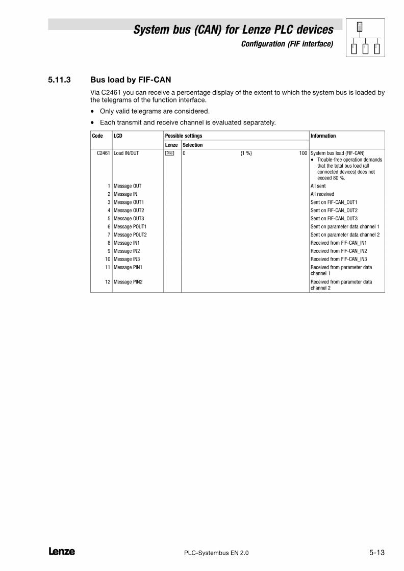
System bus (CAN) for Lenze PLC devicesConfiguration (FIF interface)
5−13l PLC−Systembus EN 2.0
5.11.3 Bus load by FIF−CAN
Via C2461 you can receive a percentage display of the extent to which the system bus is loaded bythe telegrams of the function interface.
� Only valid telegrams are considered.
� Each transmit and receive channel is evaluated separately.
Code LCD Possible settings Information
Lenze Selection
C2461 Load IN/OUT � 0 {1 %} 100 System bus load (FIF−CAN)
� Trouble−free operation demandsthat the total bus load (allconnected devices) does notexceed 80 %.
1 Message OUT All sent
2 Message IN All received
3 Message OUT1 Sent on FIF−CAN_OUT1
4 Message OUT2 Sent on FIF−CAN_OUT2
5 Message OUT3 Sent on FIF−CAN_OUT3
6 Message POUT1 Sent on parameter data channel 1
7 Message POUT2 Sent on parameter data channel 2
8 Message IN1 Received from FIF−CAN_IN1
9 Message IN2 Received from FIF−CAN_IN2
10 Message IN3 Received from FIF−CAN_IN3
11 Message PIN1 Received from parameter datachannel 1
12 Message PIN2 Received from parameter datachannel 2

System bus (CAN) for Lenze PLC devicesConfiguration (FIF interface)
5−14 lPLC−Systembus EN 2.0

System bus (CAN) for Lenze PLC devicesConfiguration (CAN−AUX interface)
6−1l PLC−Systembus EN 2.0
6 Configuration (CAN−AUX system bus interface)
By means of a corresponding function module (e. g. CAN−I/O system bus) you can use the CAN−AUXinterface of the ECSxA axis module as an additional system bus interface.
Note!
If the function module attached to the CAN−AUX interface and the integrated system bus interfaceare connected to the same system bus network, please be absolutely sure that different CANaddresses and different identifiers have been set for the interfaces!
Tip!
Changes with regard to the CAN baud rate, the CAN addresses, and the identifiers for PDOs onlyare accepted after a reset node.
A reset node can be effected by
� Reconnection of the mains
� Reset node command via NMT command. (� 2−6)
� Reset node via C0358 (� 6−8)
6.1 CAN baud rate
In order to accomplish a communication via the system bus, all nodes have to use the same baudrate for data transmission.
� The configuration of the baud rate is effected via code C2451:
Code LCD Possible settings Information
Lenze Selection
C2451 CAN1 baud rate 0 0 500 kbit/s
1 250 kbit/s
2 125 kbit/s
3 50 kbit/s
4 1000 kbit/s
System bus − baud rate
� Save changes with C0003 = 1.
� Changes are only valid afterreset node!

System bus (CAN) for Lenze PLC devicesConfiguration (CAN−AUX interface)
6−2 lPLC−Systembus EN 2.0
6.2 CAN boot−up
If the initialisation of the system bus and the associated state change from Pre−operational toOperational is not taken over by a higher−level master system, the PLC or a controller can bedesignated as a "quasi" master to accomplish this task instead.
� The configuration is effected via code C2452:
Code LCD Possible settings Information
Lenze Selection
C2452 CAN1 mst 0 0 Boot−up not active
1 Boot−up active
Device sends system bus boot−upand thus is the "quasi" master.
Delay time for system bus initialisation (boot−up)
Some nodes (e. g. HMIs) require a specific starting time after mains connection before they can betransferred to the Operational state via NMT commands by the master.
In order to ensure that even the node with the greatest starting time really is ready to receive NMTcommands, you can set a delay time. When it has expired, NMT commands can only be transmittedafter mains power−up.
� The configuration of this delay time is effected via code C2456/1:
Code LCD Possible settings Information
Lenze Selection
C2456
1
CAN1 boot−up
3000
0 {1 ms} 65000 Delay time after power−on forinitialisation via the "quasi" master

System bus (CAN) for Lenze PLC devicesConfiguration (CAN−AUX interface)
6−3l PLC−Systembus EN 2.0
6.3 Node address (Node ID)
Assign a node address − also called Node ID − within the range of 1 to 63 to each node within thesystem bus network as a definite identification.
� The same node address may not be assigned more than once within the network.
� The configuration of the node address for the CAN−AUX interface of the PLC is effected viacode C2450:
Code LCD Possible settings Information
Lenze Selection
C2450 CAN1 address 1 1 {1} 63 System bus node address
� Save changes with C0003 = 1.
� Changes are only valid afterreset node!
Allocation of the node address for the data exchange among Lenze devices
If Lenze devices are provided with node addresses in a consistent ascending order, the identifiersof the event−controlled data objects (CANaux2_IO/CANaux3_IO) are set in way by the factory whichenables a communication from one device to the other:
L
Node-ID 1
FIF-CAN2_OUT
FIF-CAN2_INFIF-CAN3_OUT
FIF-CAN3_IN
L
Node-ID 2
FIF-CAN2_OUT
FIF-CAN2_INFIF-CAN3_OUT
FIF-CAN3_IN
L
Node-ID 3
Fig. 6−1 Data exchange among Lenze devices

System bus (CAN) for Lenze PLC devicesConfiguration (CAN−AUX interface)
6−4 lPLC−Systembus EN 2.0
6.4 Identifiers of the process data objects
The identifiers for the CANaux1_IO ... CANaux3_IO process data objects are generated by theso−called basic identifier and the node address set in C2450:
Identifier � basic identifier � node address
Basic identifiers
dec hex
PDOs CANaux1_IO (cyclic process data)
CANaux1_IN 512 200
CANaux1_OUT 384 180
CANaux2_IO (event− or time−controlled process data)
CANaux2_IN 640 280
CANaux2_OUT 641 281
CANaux3_IO (event− or time−controlled process data)
CANaux3_IN 768 300
CANaux3_OUT 769 301
6.4.1 Allocation of individual identifiers
For greater system bus networks with many nodes it can be reasonable to set individual identifiersfor the CANaux1_IO ... CANaux3_IO process data objects via C2453/C2454, which are independentof the node address set in C2350:
1. Set C2453/x to "1".
– (x = subcode of the corresponding process data object):
Code LCD Possible settings Information
Lenze Selection
C2453 CAN addr sel 0 Identifier assignment under C2450 + basicidentifier
1 Identifier assignment under C2454/x
Source for the identifiers of theprocess data objects
� Save changes with C0003 = 1.
� Changes are only valid afterreset node!
1 CAN addr sel1 0 CANaux1_IN/OUT
2 CAN addr sel2 0 CANaux2_IN/OUT
3 CAN addr sel3 0 CANaux3_IN/OUT
2. Set the value which, added to "384", makes the desired identifier in C2453/x.
– (x = subcode of the corresponding process data object):
Code LCD Possible settings Information
Lenze Selection
C2454 CAN addr 1 {1} 512 Specification of individualidentifiers of the process dataobjects
1
2
3
4
5
6
IN1 addr2
OUT1 addr2
IN2 addr2
OUT2 addr2
IN3 addr2
OUT3 addr2
129
1
257
258
385
386
CANaux1_IN
CANaux1_OUT
CANaux2_IN
CANaux2_OUT
CANaux3_IN
CANaux3_OUT

System bus (CAN) for Lenze PLC devicesConfiguration (CAN−AUX interface)
6−5l PLC−Systembus EN 2.0
� Please note that the identifier of the telegram to be transmitted has to comply with theidentifier of the process data input object to be activated.
� In the case of an individual address allocation, the identifier for the process data objects iscomposed as follows:
Identifier � 384 � value of C2454/xx = subcode
� Thus, for the process data objects identifiers in the range of 385 ... 896 can be allocated.
6.4.2 Display of the identifiers set
Via C2455 you can have the identifier displayed which is set for the process data objects.
� C2455 is a display code, settings cannot be carried out via C2455.
Code LCD Possible settings Information
Lenze Selection
C2455
1
2
3
4
5
6
CAN Id
CAN1_IN Id
CAN1_OUT Id
CAN2_IN Id
CAN2_OUT Id
CAN3_IN Id
CAN3_OUT Id
� 385 {1} 896 System bus identifier
for the process data objects
CANaux1_IN
CANaux1_OUT
CANaux2_IN
CANaux2_OUT
CANaux3_IN
CANaux3_OUT

System bus (CAN) for Lenze PLC devicesConfiguration (CAN−AUX interface)
6−6 lPLC−Systembus EN 2.0
6.5 Cycle time (CANaux2_OUT/CANaux3_OUT)
The transmission of the output data of CANaux2_OUT and CANaux3_OUT can be carried out in anevent−controlled or time−controlled manner.
� The configuration of the transmission mode is effected via code C2456/x:
Code LCD Possible settings Information
Lenze Selection
C2456 0 {1} 65000
0 = event−controlled transmission
Factor to the task time fortransmitting the process dataobject
2
3
CAN2_OUT T
CAN3_OUT T
0
0
CANaux2_OUT
CANaux3_OUT
Event−controlled transmission
C2456/x = 0
� The transmission of the output data is always effected if a value has changed within the8 bytes of user data (Lenze setting).
Time−controlled transmission
C2456/x = 1 ... 65000
� The transmission of the output data is effected within the cycle time set in C2456/x (relating tothe task cycle time).
Example:
� The CAN object is used in a 10 ms task.
� Factor set via C2456/2 = 5
The CAN object is transmitted after every fifth cycle of the task, i. e. every 50 ms (10 ms x 5).
6.6 Delay time (CANaux2_OUT/CANaux3_OUT)
For the transmission of the output data of CANaux2_OUT and CANaux3_OUT a delay time can beconfigured via code C2456/4:
Code LCD Possible settings Information
Lenze Selection
C2456
4 CAN delay 20
0 {1 ms} 65000 Delay time for sending the processdata object

System bus (CAN) for Lenze PLC devicesConfiguration (CAN−AUX interface)
6−7l PLC−Systembus EN 2.0
6.7 Synchronisation
Tip!
By means of the CAN_Synchronization SB, the internal time base of the PLC can be synchronisedwith the arrival of the sync telegram.
Thus the internal calculating processes (e. g. control−oriented processes) of the PLC can besynchronised with the calculating processes of other nodes which can also process the synctelegram.
Detailed information on the CAN_Synchronization SB can be found in chapter 7.7. (� 7−23)
6.7.1 CANaux sync response
The response to the reception of a sync telegram can be configured via C2466:
Code LCD Possible settings IMPORTANT
Lenze Selection
C2466 Sync response 1 CANaux sync response
0 No response No response
1 Response to sync PLC responds to a sync telegramby sending the CANaux1_OUTobject.
6.7.2 CANaux sync identifiers
The transmission or reception identifiers of the sync telegram can be configured via C2467/C2468:
Code LCD Possible settings IMPORTANT
Lenze Selection
C2467 Sync Rx Id 128 1 {1} 256 CANaux sync Rx identifier
Receive identifier for the synctelegram
C2468 Sync Tx Id 128 1 {1} 256 CANaux sync Tx identifier
Send identifier for the synctelegram
6.7.3 CANaux sync Tx transmission cycle
The cycle time within which a sync telegram with the identifier set in C2468 is transmitted can beconfigured via C2469:
Code LCD Possible settings IMPORTANT
Lenze Selection
C2469 Sync Tx time 0 0 {1 ms} 65000
0 = Off
CANaux sync time
Sync transmission telegram cycle

System bus (CAN) for Lenze PLC devicesConfiguration (CAN−AUX interface)
6−8 lPLC−Systembus EN 2.0
6.8 Reset node
Changes with regard to the CAN baud rate, the node addresses, and the identifiers only are acceptedafter a reset node.
A reset node can be effected by
� Reconnection of the mains
� Reset node command via NMT command. (� 2−6)
� Reset node command via the CANaux_Management SB (� 8−4)
� Reset node via C2458:
Code LCD Possible settings Information
Lenze Selection
C2458 Reset node 0 0 No function
1 CANaux reset node
CANauxreset node
6.9 System bus management
Via the CANaux_Management SB,
� a reset node can be activated.
� "Communication error" and "Bus off state" can be processed in the PLC program.
� the instant of transmission of CANaux2_OUT and CANaux3_OUT can be influenced.
Tip!
Detailed information on the CANaux_Management SB can be found in chapter 8.4. (� 8−4)
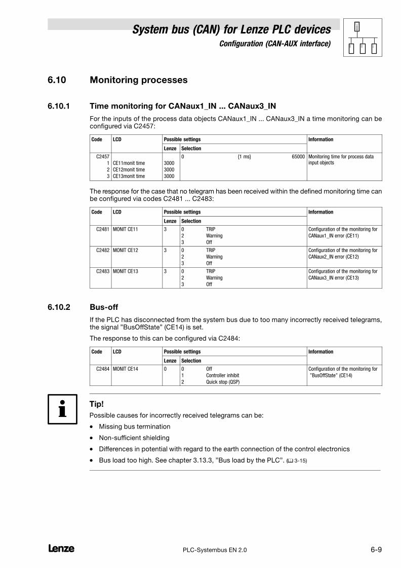
System bus (CAN) for Lenze PLC devicesConfiguration (CAN−AUX interface)
6−9l PLC−Systembus EN 2.0
6.10 Monitoring processes
6.10.1 Time monitoring for CANaux1_IN ... CANaux3_IN
For the inputs of the process data objects CANaux1_IN ... CANaux3_IN a time monitoring can beconfigured via C2457:
Code LCD Possible settings Information
Lenze Selection
C2457
1
2
3
CE11monit time
CE12monit time
CE13monit time
3000
3000
3000
0 {1 ms} 65000 Monitoring time for process datainput objects
The response for the case that no telegram has been received within the defined monitoring time canbe configured via codes C2481 ... C2483:
Code LCD Possible settings Information
Lenze Selection
C2481 MONIT CE11 3 0 TRIP
2 Warning
3 Off
Configuration of the monitoring for
CANaux1_IN error (CE11)
C2482 MONIT CE12 3 0 TRIP
2 Warning
3 Off
Configuration of the monitoring for
CANaux2_IN error (CE12)
C2483 MONIT CE13 3 0 TRIP
2 Warning
3 Off
Configuration of the monitoring for
CANaux3_IN error (CE13)
6.10.2 Bus−off
If the PLC has disconnected from the system bus due to too many incorrectly received telegrams,the signal "BusOffState" (CE14) is set.
The response to this can be configured via C2484:
Code LCD Possible settings Information
Lenze Selection
C2484 MONIT CE14 0 0 Off
1 Controller inhibit
2 Quick stop (QSP)
Configuration of the monitoring for
"BusOffState" (CE14)
Tip!
Possible causes for incorrectly received telegrams can be:
� Missing bus termination
� Non−sufficient shielding
� Differences in potential with regard to the earth connection of the control electronics
� Bus load too high. See chapter 3.13.3, "Bus load by the PLC". (� 3−15)

System bus (CAN) for Lenze PLC devicesConfiguration (CAN−AUX interface)
6−10 lPLC−Systembus EN 2.0
6.10.3 Response in the case of system bus fault messages
Overview of the system bus error sources registered by the PLC as well as of the possible settingsfor the corresponding response:
Fault message Possible settings/response
Display ErrorNo.
Meaning TRIP Message Warning Fault/QSP
Off Code
CE11 122 Communication error CANaux1_IN
(Time monitoring can be set via C2457/1)
− − • C2481
CE12 123 CANaux2_IN communication error
(Time monitoring can be set via C2457/2)
− − • C2482
CE13 124 CANaux3_IN communication error
(Time monitoring can be set via C2457/3)
− − • C2483
CE14 125 BUS−OFF state
(too many faulty telegrams were received)
− − • C2484
• Lenze setting
Possible
− Not possible

System bus (CAN) for Lenze PLC devicesConfiguration (CAN−AUX interface)
6−11l PLC−Systembus EN 2.0
6.11 Diagnostics
The following codes can be used for diagnostics purposes:
Code Information displayed Information
C2459 CAN−AUX operating status Chapter 6.11.1 � 6−11
C2460 Number of the telegrams sent and received Chapter 6.11.2 � 6−12
C2461 Bus load (in %) Chapter 6.11.3 � 6−13
� Settings cannot be carried out via these codes.
6.11.1 Operating status of the CAN−AUX interface
Via C2459 you can have the operating status of the system bus displayed:
Code LCD Possible settings Information
Lenze Selection
C2459 CAN1 state � 0 Operational
1 Pre−operational
2 Warning
3 Bus off
System bus status (CAN−AUX)
C2459 Operating status Information
0 Operational The system bus is fully functional. The PLC can transmit and receive parameter and process data.
1 Pre−operational The PLC can transmit and receive parameter data. Process data, however, are ignored.
A status change from Pre−operational to Operational can be effected by:
� the CAN master � 3−2
� a reset node
– via C2458, if the PLC has been configured as a "quasi" master. � 6−8
– via the binary input signal "Reset node" at the CANaux_Management SB � 7−20
2 Warning The PLC has received faulty telegrams and is only involved in the system bus passively, i. e. no data can besent from the PLC anymore.
Possible causes:
� Missing bus termination
� Non−sufficient shielding
� Differences in potential with regard to the earth connection of the control electronics
� Bus load too high
� PLC is not connected to the system bus.
3 Bus−off The PLC has disconnected from the system bus due to too many faultily received telegrams.
� The response to this status can be configured via C2484. � 6−9

System bus (CAN) for Lenze PLC devicesConfiguration (CAN−AUX interface)
6−12 lPLC−Systembus EN 2.0
6.11.2 Telegram counter
Via C2460 you can have the number of the telegrams sent and received by the PLC viaCANaux1_IO ... CANaux3_IO.
� Only the telegrams which are valid for the PLC are counted.
� Each transmit and receive channel is evaluated separately.
� The max. counter content is 65535 (16 bit); if this value is exceeded, the correspondingcounter starts with 0 again.
Code LCD Possible settings Information
Lenze Selection
C2460 CAN message � 0 {1} 65535 System bus telegram counter
(number of telegrams)
� For values > 65535 countingrestarts with 0.
1 Message OUT All sent
2 Message IN All received
3 Message OUT1 Sent on CANaux_OUT1
4 Message OUT2 Sent on CANaux_OUT2
5 Message OUT3 Sent on CANaux_OUT3
6 Message POUT1 Sent on parameter data channel 1
7 Message POUT2 Sent on parameter data channel 2
8 Message IN1 Received from CANaux_IN1
9 Message IN2 Received from CANaux_IN2
10 Message IN3 Received from CANaux_IN3
11 Message PIN1 Received from parameter datachannel 1
12 Message PIN2 Received from parameter datachannel 2

System bus (CAN) for Lenze PLC devicesConfiguration (CAN−AUX interface)
6−13l PLC−Systembus EN 2.0
6.11.3 Bus load by CAN−AUX
Via C2461 you can receive a percentage display of the extent to which the system bus is loaded bythe telegrams of the CAN−AUX interface.
� Only valid telegrams are considered.
� Each transmit and receive channel is evaluated separately.
Code LCD Possible settings Information
Lenze Selection
C2461 Load IN/OUT � 0 {1 %} 100 System bus − bus load
(CAN−AUX)
� Trouble−free operation demandsthat the total bus load (allconnected devices) does notexceed 80 %.
1 Message OUT All sent
2 Message IN All received
3 Message OUT1 Sent on CANaux_OUT1
4 Message OUT2 Sent on CANaux_OUT2
5 Message OUT3 Sent on CANaux_OUT3
6 Message POUT1 Sent on parameter data channel 1
7 Message POUT2 Sent on parameter data channel 2
8 Message IN1 Received from CANaux_IN1
9 Message IN2 Received from CANaux_IN2
10 Message IN3 Received from CANaux_IN3
11 Message PIN1 Received from parameter datachannel 1
12 Message PIN2 Received from parameter datachannel 2

System bus (CAN) for Lenze PLC devicesConfiguration (CAN−AUX interface)
6−14 lPLC−Systembus EN 2.0

System bus (CAN) for Lenze PLC devicesCAN system blocks
7.1 CAN1_IO (node number: 31) − 9300 Servo PLC
7−1L PLC−Systembus EN 2.0
7 CAN system blocks
7.1 CAN1_IO (node number: 31) − 9300 Servo PLC
This SB serves to transmit cyclic process data via the system bus.
� For the transmission a sync telegram is required, which has to be generated by a differentnode. (� 2−9)
CAN1_nInW1_a
C0866/1
CAN1_dnInD1_p
CAN1_wDctrlCtrl
CAN1_bCtrlB0_b
CAN1_bCtrlB1_b
CAN1_bCtrlB2_b
CAN1_bCtrlQuickstop_b
CAN1_bCtrlB4_b
CAN1_bCtrlB5_b
CAN1_bCtrlB6_b
CAN1_bCtrlB7_b
CAN1_bCtrlDisable_b
CAN1_bCtrlCInhibit_b
CAN1_bCtrlTripSet_b
CAN1_bCtrlTripReset_b
CAN1_bCtrlB12_b
CAN1_bCtrlB13_b
CAN1_bCtrlB14_b
CAN1_bCtrlB15_b
CAN1_nInW2_a
CAN1_bInB _b0...15
CAN1_nInW3_a
CAN1_bInB _b16...31
System bus interface
Controldatainput
WORD
Byte
7
8
5
6
3
4
1
2
16 xBOOL
Byte
7
8
5
6
3
4
1
2
WORDCAN1_wDctrlStat
CAN1_nOutW1_a
CAN1_nOutW2_a
CAN1_bFDO _b0...15
CAN1_nOutW3_a
CAN1_bFDO _b16...31
CAN1_dnOutD1_p
CAN1_IO
Statedataoutput
3
8
9
10
11
0
1
2
3
5
6
7
12
13
14
15
Bit:
C0866/2
WORD
C0866/3
WORD
16 x BOOL
16 x BOOL
C0867/1
DINT
WORD
C0868/1
WORD
C0868/2
WORD
C0868/3
WORD
16 x BOOL
16 x BOOL
C0151/1
DINT
Output user data(8 bytes)
Input user data(8 bytes)
L
H
L
H
C0151/1
C0863/2
C0863/1
C0869/1
Fig. 7−1 CAN1_IO system block
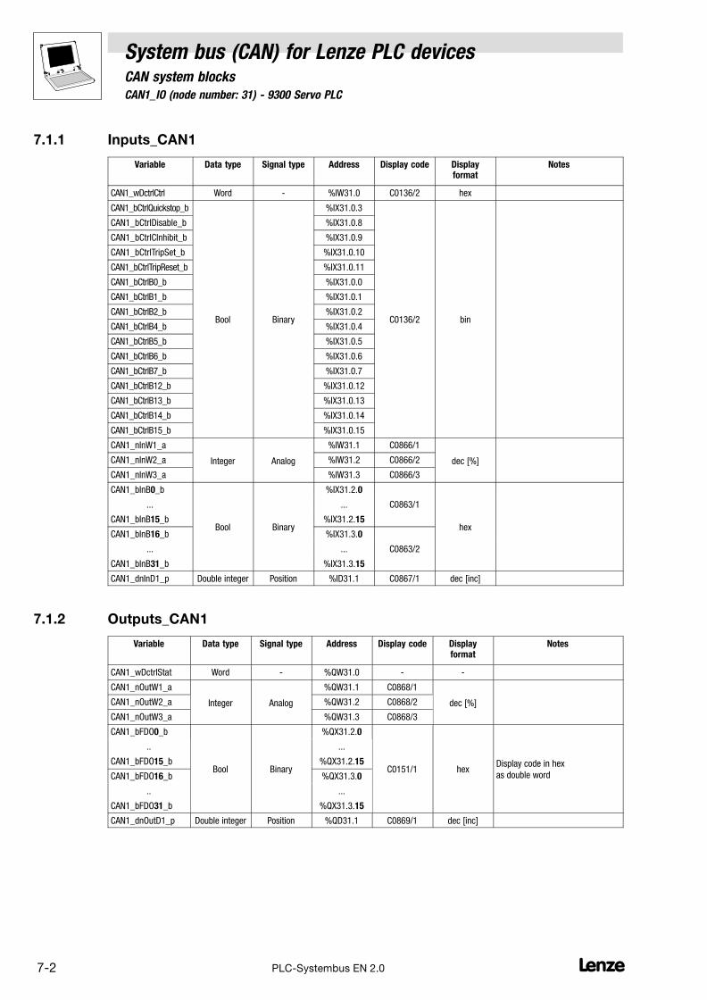
7.1 CAN1_IO (node number: 31) − 9300 Servo PLC
System bus (CAN) for Lenze PLC devicesCAN system blocks
7−2 LPLC−Systembus EN 2.0
7.1.1 Inputs_CAN1
Variable Data type Signal type Address Display code Displayformat
Notes
CAN1_wDctrlCtrl Word − %IW31.0 C0136/2 hex
CAN1_bCtrlQuickstop_b
Bool Binary
%IX31.0.3
C0136/2 bin
CAN1_bCtrlDisable_b %IX31.0.8
CAN1_bCtrlCInhibit_b %IX31.0.9
CAN1_bCtrlTripSet_b %IX31.0.10
CAN1_bCtrlTripReset_b %IX31.0.11
CAN1_bCtrlB0_b %IX31.0.0
CAN1_bCtrlB1_b %IX31.0.1
CAN1_bCtrlB2_b %IX31.0.2
CAN1_bCtrlB4_b %IX31.0.4
CAN1_bCtrlB5_b %IX31.0.5
CAN1_bCtrlB6_b %IX31.0.6
CAN1_bCtrlB7_b %IX31.0.7
CAN1_bCtrlB12_b %IX31.0.12
CAN1_bCtrlB13_b %IX31.0.13
CAN1_bCtrlB14_b %IX31.0.14
CAN1_bCtrlB15_b %IX31.0.15
CAN1_nInW1_a
Integer Analog
%IW31.1 C0866/1
dec [%]CAN1_nInW2_a %IW31.2 C0866/2
CAN1_nInW3_a %IW31.3 C0866/3
CAN1_bInB0_b
Bool Binary
%IX31.2.0
hex
... ... C0863/1
CAN1_bInB15_b %IX31.2.15
CAN1_bInB16_b %IX31.3.0
... ... C0863/2
CAN1_bInB31_b %IX31.3.15
CAN1_dnInD1_p Double integer Position %ID31.1 C0867/1 dec [inc]
7.1.2 Outputs_CAN1
Variable Data type Signal type Address Display code Displayformat
Notes
CAN1_wDctrlStat Word − %QW31.0 − −
CAN1_nOutW1_a
Integer Analog
%QW31.1 C0868/1
dec [%]CAN1_nOutW2_a %QW31.2 C0868/2
CAN1_nOutW3_a %QW31.3 C0868/3
CAN1_bFDO0_b
Bool Binary
%QX31.2.0
C0151/1 hexDisplay code in hex
as double word
.. ...
CAN1_bFDO15_b %QX31.2.15
CAN1_bFDO16_b %QX31.3.0
.. ...
CAN1_bFDO31_b %QX31.3.15
CAN1_dnOutD1_p Double integer Position %QD31.1 C0869/1 dec [inc]

System bus (CAN) for Lenze PLC devicesCAN system blocks
7.1 CAN1_IO (node number: 31) − 9300 Servo PLC
7−3L PLC−Systembus EN 2.0
7.1.3 Process data telegram
The process data telegram consists of an identifier and 8 bytes of user data.
11bit 8 bytes user data
Identifier Byte 1 Byte 2 Byte 3 Byte 4 Byte 5 Byte 6 Byte 7 Byte 8
Information on the identifier can be found in chapter 2.4.1. (� 2−3)
7.1.4 Assignment of the user data to variables
Several variables of different data types are assigned to the user data to be transmitted and received.Thus, the data in the PLC program can be optionally interpreted as:
� binary information (1 bit)
� status word/quasi−analog value (16 bit)
� angle information (32 bit)
Variables for user data to be transmitted
User data Assigned variables
Byte Bit Variable (1 bit) Variable (16 bit) Variable (32 bit)
1 0...7CAN1_wDctrlStat
2 0...7
3 0...7CAN1_nOutW1_a
4 0...7
5 0
...
7
CAN1_bFDO0_b
...
CAN1_bFDO7_bCAN1_nOutW2_a
CAN1_dnOutD1_p
6 0
...
7
CAN1_bFDO8_b
...
CAN1_bFDO15_b
7 0
...
7
CAN1_bFDO16_b
...
CAN1_bFDO23_bCAN1_nOutW3_a
8 0
...
7
CAN1_bFDO24_b
...
CAN1_bFDO31_b
Note!
Avoid simultaneous overwriting via different variable types to ensure data consistency.
For instance, if you want to write bytes 5 and 6, only use the variable CAN1_dnOutD1_p,CAN1_nOutW2_a, or only the variables CAN1_bFDO0_b ... CAN1_bFDO15_b for this purpose!

7.1 CAN1_IO (node number: 31) − 9300 Servo PLC
System bus (CAN) for Lenze PLC devicesCAN system blocks
7−4 LPLC−Systembus EN 2.0
Variables for received user data
User data Assigned variables
Byte Bit Variable (1 bit) Variable (16 bit) Variable (32 bit)
1 0 CAN1_bInB0_b
CAN1_wDctrlCtrl
1 CAN1_bInB1_b
2 CAN1_bInB2_b
3 CAN1_bCtrlQuickstop_b
4 CAN1_bInB4_b
5 CAN1_bInB5_b
6 CAN1_bInB6_b
7 CAN1_bInB7_b
2 0 CAN1_bCtrlDisable_b
1 CAN1_bCtrlCInhibit_b
2 CAN1_bCtrlTripSet_b
3 CAN1_bCtrlTripReset_b
4 CAN1_bInB12_b
5 CAN1_bInB13_b
6 CAN1_bInB14_b
7 CAN1_bInB15_b
3 0...7CAN1_nInW1_a
4 0...7
5 0
...
7
CAN1_bInB0_b
...
CAN1_bInB7_bCAN1_nInW2_a
CAN1_dnInD1_p
6 0
...
7
CAN1_bInB8_b
...
CAN1_bInB15_b
7 0
...
7
CAN1_bInB16_b
...
CAN1_bInB23_bCAN1_nInW3_a
8 0
...
7
CAN1_bInB24_b
...
CAN1_bInB31_b

System bus (CAN) for Lenze PLC devicesCAN system blocks
7.1 CAN1_IO (node number: 31) − 9300 Servo PLC
7−5L PLC−Systembus EN 2.0
7.1.5 Transferring status and control information of the device control
Via the user data bytes 1 and 2, you can exchange status and control information of the devicecontrol (DCTRL) between different 9300 Servo PLCs via the system bus (CAN) in a simple manner.
Sending the status word of the DCTRL SB
Connect the variable DCTRL_wStat of the DCTRL SB to the variable CAN1_wDctrlStat to transferthe status word of the DCTRL SB via the user data bytes 1 and 2.
Tip!
In addition to signals such as IMP and CINH, the SB status word DCTRL contains some freelyassignable signals which can be overwritten via the variables DCTRL_bStateB.._b of the DCTRL SB.
Detailed information on the DCTRL SB can be found in the "9300 Servo PLC" Online Manual.
Transferring the control word to the DCTRL SB
Connect the variable CAN1_wDctrlCtrl to the variable DCTRL_wCAN1Ctrl of the DCTRL SB totransfer the control word received via the user data bytes 1 and 2 to the DCTRL SB.
Tip!
The control signals for the functions quick stop (QSP), DISABLE, CINH, TRIP−SET, and TRIP−RESETcan be additionally read out and processed via the following variables:
� CAN1_bCtrlQuickstop_b
� CAN1_bCtrlDisable_b
� CAN1_bCtrlInhibit_b
� CAN1_bCtrlTripSet_b
� CAN1_bCtrlTripReset_b
The remaining 11 bits (CAN1_bCtrlB..._b) can be used for controlling further functions/functionblocks.
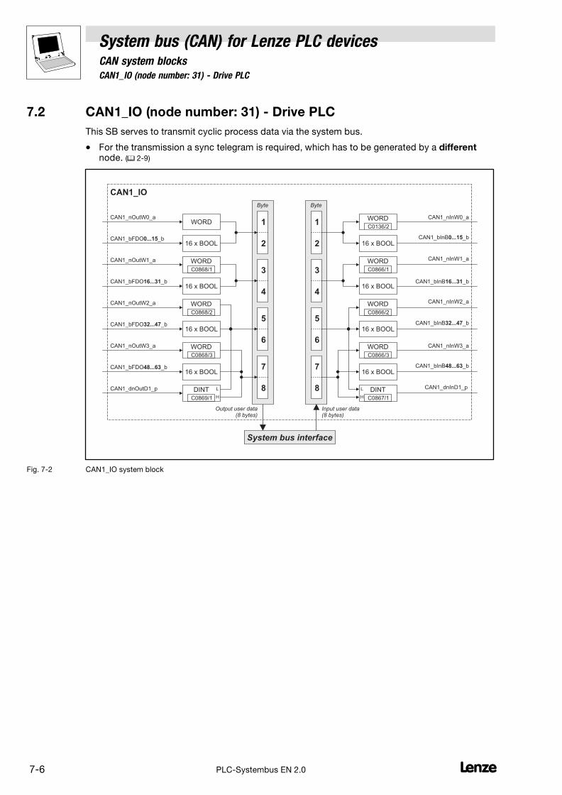
7.2 CAN1_IO (node number: 31) − Drive PLC
System bus (CAN) for Lenze PLC devicesCAN system blocks
7−6 LPLC−Systembus EN 2.0
7.2 CAN1_IO (node number: 31) − Drive PLC
This SB serves to transmit cyclic process data via the system bus.
� For the transmission a sync telegram is required, which has to be generated by a differentnode. (� 2−9)
CAN1_nInW0_a
CAN1_nInW1_a
CAN1_bInB _b0...15
CAN1_bInB _b16...31
System bus interface
Byte
7
8
5
6
3
4
1
2
Byte
7
8
5
6
3
4
1
2
CAN1_nOutW0_a
CAN1_nOutW1_a
CAN1_nOutW2_a
CAN1_bFDO _b16...31
CAN1_dnOutD1_p
CAN1_IO
DINT
WORD
WORD
WORD
16 x BOOL
DINT
Output user data(8 bytes)
Input user data(8 bytes)
L
H
L
H
CAN1_bFDO _b0...1516 x BOOL
CAN1_nOutW3_a WORD
CAN1_nInW2_a
CAN1_nInW3_a
CAN1_dnInD1_p
C0868/1
C0869/1
C0868/2
C0868/3
C0867/1
CAN1_bFDO _b32...4716 x BOOL
CAN1_bFDO _b48...6316 x BOOL
WORD
WORD
16 x BOOL
16 x BOOL
WORD
C0866/1
C0866/2
C0866/3
16 x BOOL
16 x BOOL
WORD
C0136/2
CAN1_bInB _b32...47
CAN1_bInB _b48...63
Fig. 7−2 CAN1_IO system block

System bus (CAN) for Lenze PLC devicesCAN system blocks
7.2 CAN1_IO (node number: 31) − Drive PLC
7−7L PLC−Systembus EN 2.0
7.2.1 Inputs_CAN1
Variable Data type Signal type Address Display code Displayformat
Notes
CAN1_nInW0_a Integer Analog %IW31.0 C0136/2 dec [%]
CAN1_bInB0_b %IX31.0.0
... Bool Binary ... C0863/1 hex
CAN1_bInB15_b %IX31.0.15
CAN1_nInW1_a Integer Analog %IW31.1 C0866/1 dec [%]
CAN1_bInB16_b %IX31.1.0
... Bool Binary ... C0863/2 hex
CAN1_bInB31_b %IX31.1.15
CAN1_nInW2_a Integer Analog %IW31.2 C0866/2 dec [%]
CAN1_bInB32_b %IX31.2.0
... Bool Binary ...
CAN1_bInB47_b %IX31.2.15
CAN1_nInW3_a Integer Analog %IW31.3 C0866/3 dec [%]
CAN1_bInB48_b %IX31.3.0
... Bool Binary ...
CAN1_bInB63_b %IX31.3.15
CAN1_dnInD1_p Double integer Position %ID31.1 C0867/1 dec [inc]
7.2.2 Outputs_CAN1
Variable Data type Signal type Address Display code Displayformat
Notes
CAN1_nOutW0_a Integer Analog %QW31.0 − −
CAN1_bFDO0_b
Bool Binary
%QX31.0.0
− hexDisplay code in hex
as double word.. ..
CAN1_bFDO15_b %QX31.0.15
CAN1_nOutW1_a Integer Analog %QW31.1 C0868/1 dec [%]
CAN1_bFDO16_b
Bool Binary
%QX31.1.0
− hexDisplay code in hex
as double word.. ..
CAN1_bFDO31_b %QX31.1.15
CAN1_nOutW2_a Integer Analog %QW31.2 C0868/2 dec [%]
CAN1_bFDO32_b
Bool Binary
%QX31.2.0
− hexDisplay code in hex
as double word.. ..
CAN1_bFDO47_b %QX31.2.15
CAN1_nOutW3_a Integer Analog %QW31.3 C0868/3 dec [%]
CAN1_bFDO48_b
Bool Binary
%QX31.3.0
− hexDisplay code in hex
as double word.. ..
CAN1_bFDO63_b %QX31.3.15
CAN1_dnOutD1_p Double integer Position %QD31.1 C0869/1 dec [inc]

7.2 CAN1_IO (node number: 31) − Drive PLC
System bus (CAN) for Lenze PLC devicesCAN system blocks
7−8 LPLC−Systembus EN 2.0
7.2.3 Process data telegram
The process data telegram consists of an identifier and 8 bytes of user data.
11bit 8 bytes user data
Identifier Byte 1 Byte 2 Byte 3 Byte 4 Byte 5 Byte 6 Byte 7 Byte 8
Information on the identifier can be found in chapter 2.4.1. (� 2−3)
7.2.4 Assignment of the user data to variables
Several variables of different data types are assigned to the user data to be transmitted and received.Thus, the data in the PLC program can be optionally interpreted as:
� binary information (1 bit)
� status word/quasi−analog value (16 bit)
� angle information (32 bit)
Variables for user data to be transmitted
User data Assigned variables
Byte Bit Variable (1 bit) Variable (16 bit) Variable (32 bit)
1 0
...
7
CAN1_bFDO0_b
...
CAN1_bFDO7_bCAN1_nOutW0_a
2 0
...
7
CAN1_bFDO8_b
...
CAN1_bFDO15_b
3 0
...
7
CAN1_bFDO16_b
...
CAN1_bFDO23_bCAN1_nOutW1_a
4 0
...
7
CAN1_bFDO24_b
...
CAN1_bFDO31_b
5 0
...
7
CAN1_bFDO32_b
...
CAN1_bFDO39_bCAN1_nOutW2_a
CAN1_dnOutD1_p
6 0
...
7
CAN1_bFDO40_b
...
CAN1_bFDO47_b
7 0
...
7
CAN1_bFDO48_b
...
CAN1_bFDO55_bCAN1_nOutW3_a
8 0
...
7
CAN1_bFDO56_b
...
CAN1_bFDO63_b
Note!
Avoid simultaneous overwriting via different variable types to ensure data consistency.
For instance, if you want to write bytes 5 and 6, only use the variable CAN1_dnOutD1_p,CAN1_nOutW2_a, or only the variables CAN1_bFDO32_b ... CAN1_bFDO47_b for this purpose!

System bus (CAN) for Lenze PLC devicesCAN system blocks
7.2 CAN1_IO (node number: 31) − Drive PLC
7−9L PLC−Systembus EN 2.0
Variables for received user data
User data Assigned variables
Byte Bit Variable (1 bit) Variable (16 bit) Variable (32 bit)
1 0
...
7
CAN1_bInB0_b
...
CAN1_bInB7_bCAN1_nInW0_a
2 0
...
7
CAN1_bInB8_b
...
CAN1_bInB15_b
3 0
...
7
CAN1_bInB16_b
...
CAN1_bInB23_bCAN1_nInW1_a
4 0
...
7
CAN1_bInB24_b
...
CAN1_bInB31_b
5 0
...
7
CAN1_bInB32_b
...
CAN1_bInB39_bCAN1_nInW2_a
CAN1_dnInD1_p
6 0
...
7
CAN1_bInB40_b
...
CAN1_bInB47_b
7 0
...
7
CAN1_bInB48_b
...
CAN1_bInB55_bCAN1_nInW3_a
8 0
...
7
CAN1_bInB56_b
...
CAN1_bInB63_b

7.3 CAN1_IO (node number: 31) − ECSxA
System bus (CAN) for Lenze PLC devicesCAN system blocks
7−10 LPLC−Systembus EN 2.0
7.3 CAN1_IO (node number: 31) − ECSxA
This SB serves to transmit cyclic process data via the system bus.
� For the transmission a sync telegram is required, which has to be generated by a differentnode. (� 2−9)
CAN1_nInW0_a
CAN1_nInW1_a
CAN1_bInB _b0...15
CAN1_bInB _b16...31
System bus interface
Byte
7
8
5
6
3
4
1
2
Byte
7
8
5
6
3
4
1
2
CAN1_nOutW0_a
CAN1_nOutW1_a
CAN1_nOutW2_a
CAN1_bFDO _b16...31
CAN1_dnOutD1_p
CAN1_IO
DINT
WORD
WORD
WORD
16 x BOOL
DINT
Output user data(8 bytes)
Input user data(8 bytes)
L
H
L
H
CAN1_bFDO _b0...1516 x BOOL
CAN1_nOutW3_a WORD
CAN1_nInW2_a
CAN1_nInW3_a
CAN1_dnInD1_p
C0868/1
C0869/1
C0868/2
C0868/3
C0867/1
CAN1_bFDO _b32...4716 x BOOL
CAN1_bFDO _b48...6316 x BOOL
WORD
WORD
16 x BOOL
16 x BOOL
WORD
C0866/1
C0866/2
C0866/3
16 x BOOL
16 x BOOL
WORD
C0136/2
CAN1_bInB _b32...47
CAN1_bInB _b48...63
Fig. 7−3 CAN1_IO system block

System bus (CAN) for Lenze PLC devicesCAN system blocks
7.3 CAN1_IO (node number: 31) − ECSxA
7−11L PLC−Systembus EN 2.0
7.3.1 Inputs_CAN1
Variable Data type Signal type Address Display code Displayformat
Notes
CAN1_nInW0_a Integer Analog %IW31.0 C0136/2 dec [%]
CAN1_bInB0_b %IX31.0.0
... Bool Binary ... C0863/1 hex
CAN1_bInB15_b %IX31.0.15
CAN1_nInW1_a Integer Analog %IW31.1 C0866/1 dec [%]
CAN1_bInB16_b %IX31.1.0
... Bool Binary ... C0863/2 hex
CAN1_bInB31_b %IX31.1.15
CAN1_nInW2_a Integer Analog %IW31.2 C0866/2 dec [%]
CAN1_bInB32_b %IX31.2.0
... Bool Binary ...
CAN1_bInB47_b %IX31.2.15
CAN1_nInW3_a Integer Analog %IW31.3 C0866/3 dec [%]
CAN1_bInB48_b %IX31.3.0
... Bool Binary ...
CAN1_bInB63_b %IX31.3.15
CAN1_dnInD1_p Double integer Position %ID31.1 C0867/1 dec [inc]
7.3.2 Outputs_CAN1
Variable Data type Signal type Address Display code Displayformat
Notes
CAN1_nOutW0_a Integer Analog %QW31.0 − −
CAN1_bFDO0_b
Bool Binary
%QX31.0.0
− hexDisplay code in hex
as double word.. ..
CAN1_bFDO15_b %QX31.0.15
CAN1_nOutW1_a Integer Analog %QW31.1 C0868/1 dec [%]
CAN1_bFDO16_b
Bool Binary
%QX31.1.0
− hexDisplay code in hex
as double word.. ..
CAN1_bFDO31_b %QX31.1.15
CAN1_nOutW2_a Integer Analog %QW31.2 C0868/2 dec [%]
CAN1_bFDO32_b
Bool Binary
%QX31.2.0
− hexDisplay code in hex
as double word.. ..
CAN1_bFDO47_b %QX31.2.15
CAN1_nOutW3_a Integer Analog %QW31.3 C0868/3 dec [%]
CAN1_bFDO48_b
Bool Binary
%QX31.3.0
− hexDisplay code in hex
as double word.. ..
CAN1_bFDO63_b %QX31.3.15
CAN1_dnOutD1_p Double integer Position %QD31.1 C0869/1 dec [inc]

7.3 CAN1_IO (node number: 31) − ECSxA
System bus (CAN) for Lenze PLC devicesCAN system blocks
7−12 LPLC−Systembus EN 2.0
7.3.3 Process data telegram
The process data telegram consists of an identifier and 8 bytes of user data.
11bit 8 bytes user data
Identifier Byte 1 Byte 2 Byte 3 Byte 4 Byte 5 Byte 6 Byte 7 Byte 8
Information on the identifier can be found in chapter 2.4.1. (� 2−3)
7.3.4 Assignment of the user data to variables
Several variables of different data types are assigned to the user data to be transmitted and received.Thus, the data in the PLC program can be optionally interpreted as:
� Binary information (1 bit)
� Status word/quasi−analog value (16 bit)
� Angle information (32 bit)
Variables for user data to be transmitted
User data Assigned variables
Byte Bit Variable (1 bit) Variable (16 bit) Variable (32 bit)
1 0
...
7
CAN1_bFDO0_b
...
CAN1_bFDO7_bCAN1_nOutW0_a
2 0
...
7
CAN1_bFDO8_b
...
CAN1_bFDO15_b
3 0
...
7
CAN1_bFDO16_b
...
CAN1_bFDO23_bCAN1_nOutW1_a
4 0
...
7
CAN1_bFDO24_b
...
CAN1_bFDO31_b
5 0
...
7
CAN1_bFDO32_b
...
CAN1_bFDO39_bCAN1_nOutW2_a
CAN1_dnOutD1_p
6 0
...
7
CAN1_bFDO40_b
...
CAN1_bFDO47_b
7 0
...
7
CAN1_bFDO48_b
...
CAN1_bFDO55_bCAN1_nOutW3_a
8 0
...
7
CAN1_bFDO56_b
...
CAN1_bFDO63_b
Note!
Avoid simultaneous overwriting via different variable types to ensure data consistency.
For instance, if you want to write the bytes 5 and 6, only use the variable CAN1_dnOutD1_p,CAN1_nOutW2_a, or only the variables CAN1_bFDO32_b ... CAN1_bFDO47_b for this purpose!

System bus (CAN) for Lenze PLC devicesCAN system blocks
7.3 CAN1_IO (node number: 31) − ECSxA
7−13L PLC−Systembus EN 2.0
Variables for received user data
User data Assigned variables
Byte Bit Variable (1 bit) Variable (16 bit) Variable (32 bit)
1 0
...
7
CAN1_bInB0_b
...
CAN1_bInB7_bCAN1_nInW0_a
2 0
...
7
CAN1_bInB8_b
...
CAN1_bInB15_b
3 0
...
7
CAN1_bInB16_b
...
CAN1_bInB23_bCAN1_nInW1_a
4 0
...
7
CAN1_bInB24_b
...
CAN1_bInB31_b
5 0
...
7
CAN1_bInB32_b
...
CAN1_bInB39_bCAN1_nInW2_a
CAN1_dnInD1_p
6 0
...
7
CAN1_bInB40_b
...
CAN1_bInB47_b
7 0
...
7
CAN1_bInB48_b
...
CAN1_bInB55_bCAN1_nInW3_a
8 0
...
7
CAN1_bInB56_b
...
CAN1_bInB63_b

7.4 CAN2_IO (node number: 32)
System bus (CAN) for Lenze PLC devicesCAN system blocks
7−14 LPLC−Systembus EN 2.0
7.4 CAN2_IO (node number: 32)
This SB serves to transmit event−controlled or time−controlled process data via the system bus.
� The setting of the transmission mode (event− or time−controlled) is effected via C0356. (� 3−6)
� A sync telegram is not required.
CAN2_nInW1_a
CAN2_nInW2_a
CAN2_bInB _b0...15
CAN2_bInB _b16...31
System bus interface
Byte
7
8
5
6
3
4
1
2
Byte
7
8
5
6
3
4
1
2
CAN2_nOutW1_a
CAN2_nOutW2_a
CAN2_nOutW3_a
CAN2_bFDO _b16...31
CAN2_dnOutD1_p
CAN2_IO
DINT
WORD
WORD
WORD
16 x BOOL
DINT
Output user data(8 bytes)
Input user data(8 bytes)
L
H
L
H
CAN2_bFDO _b0...1516 x BOOL
CAN2_nOutW4_a WORD
WORD
WORD
16 x BOOL
16 x BOOL
CAN2_nInW3_a
CAN2_nInW4_a
WORD
WORD
CAN2_dnInD1_p
C0868/4
C0868/5
C0869/2
C0868/6
C0868/7
C0866/4
C0866/5
C0863/3
C0863/4
C0867/2
C0866/6
C0866/7
Fig. 7−4 CAN2_IOsystem block
Tip!
Via C0357/2 you can set the monitoring time for the data reception. (Lenze setting: 3000 ms)
� Further information on this subject can be found in chapter 3.12.1. (� 3−11)
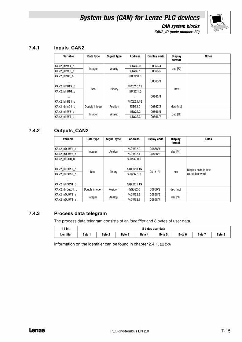
System bus (CAN) for Lenze PLC devicesCAN system blocks
7.4 CAN2_IO (node number: 32)
7−15L PLC−Systembus EN 2.0
7.4.1 Inputs_CAN2
Variable Data type Signal type Address Display code Displayformat
Notes
CAN2_nInW1_aInteger Analog
%IW32.0 C0866/4dec [%]
CAN2_nInW2_a %IW32.1 C0866/5
CAN2_bInB0_b
Bool Binary
%IX32.0.0
hex
... ... C0863/3
CAN2_bInB15_b %IX32.0.15
CAN2_bInB16_b %IX32.1.0
... ... C0863/4
CAN2_bInB31_b %IX32.1.15
CAN2_dnInD1_p Double integer Position %ID32.0 C0867/2 dec [inc]
CAN2_nInW3_aInteger Analog
%IW32.2 C0866/6dec [%]
CAN2_nInW4_a %IW32.3 C0866/7
7.4.2 Outputs_CAN2
Variable Data type Signal type Address Display code Displayformat
Notes
CAN2_nOutW1_aInteger Analog
%QW32.0 C0868/4dec [%]
CAN2_nOutW2_a %QW32.1 C0868/5
CAN2_bFDO0_b
Bool Binary
%QX32.0.0
C0151/2 hexDisplay code in hex
as double word
... ...
CAN2_bFDO15_b %QX32.0.15
CAN2_bFDO16_b %QX32.1.0
... ...
CAN2_bFDO31_b %QX32.1.15
CAN2_dnOutD1_p Double integer Position %QD32.0 C0869/2 dec [inc]
CAN2_nOutW3_aInteger Analog
%QW32.2 C0868/6dec [%]
CAN2_nOutW4_a %QW32.3 C0868/7
7.4.3 Process data telegram
The process data telegram consists of an identifier and 8 bytes of user data.
11 bit 8 bytes user data
Identifier Byte 1 Byte 2 Byte 3 Byte 4 Byte 5 Byte 6 Byte 7 Byte 8
Information on the identifier can be found in chapter 2.4.1. (� 2−3)
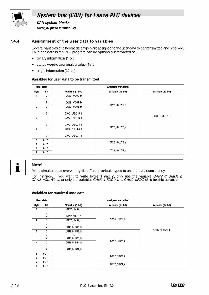
7.4 CAN2_IO (node number: 32)
System bus (CAN) for Lenze PLC devicesCAN system blocks
7−16 LPLC−Systembus EN 2.0
7.4.4 Assignment of the user data to variables
Several variables of different data types are assigned to the user data to be transmitted and received.Thus, the data in the PLC program can be optionally interpreted as:
� binary information (1 bit)
� status word/quasi−analog value (16 bit)
� angle information (32 bit)
Variables for user data to be transmitted
User data Assigned variables
Byte Bit Variable (1 bit) Variable (16 bit) Variable (32 bit)
1 0
...
7
CAN2_bFDO0_b
...
CAN2_bFDO7_bCAN2_nOutW1_a
CAN2_dnOutD1_p
2 0
...
7
CAN2_bFDO8_b
...
CAN2_bFDO15_b
3 0
...
7
CAN2_bFDO16_b
...
CAN2_bFDO23_bCAN2_nOutW2_a
4 0
...
7
CAN2_bFDO24_b
...
CAN2_bFDO31_b
5 0...7CAN2_nOutW3_a
6 0...7
7 0...7CAN2_nOutW4_a
8 0...7
Note!
Avoid simultaneous overwriting via different variable types to ensure data consistency.
For instance, if you want to write bytes 1 and 2, only use the variable CAN2_dnOutD1_p,CAN2_nOutW2_a, or only the variables CAN2_bFDO0_b ... CAN2_bFDO15_b for this purpose!
Variables for received user data
User data Assigned variables
Byte Bit Variable (1 bit) Variable (16 bit) Variable (32 bit)
1 0
...
7
CAN2_bInB0_b
...
CAN2_bInB7_bCAN2_nInW1_a
CAN2_dnInD1_p
2 0
...
7
CAN2_bInB8_b
...
CAN2_bInB15_b
3 0
...
7
CAN2_bInB16_b
...
CAN2_bInB23_bCAN2_nInW2_a
4 0
...
7
CAN2_bInB24_b
...
CAN2_bInB31_b
5 0...7CAN2_nInW3_a
6 0...7
7 0...7CAN2_nInW4_a
8 0...7
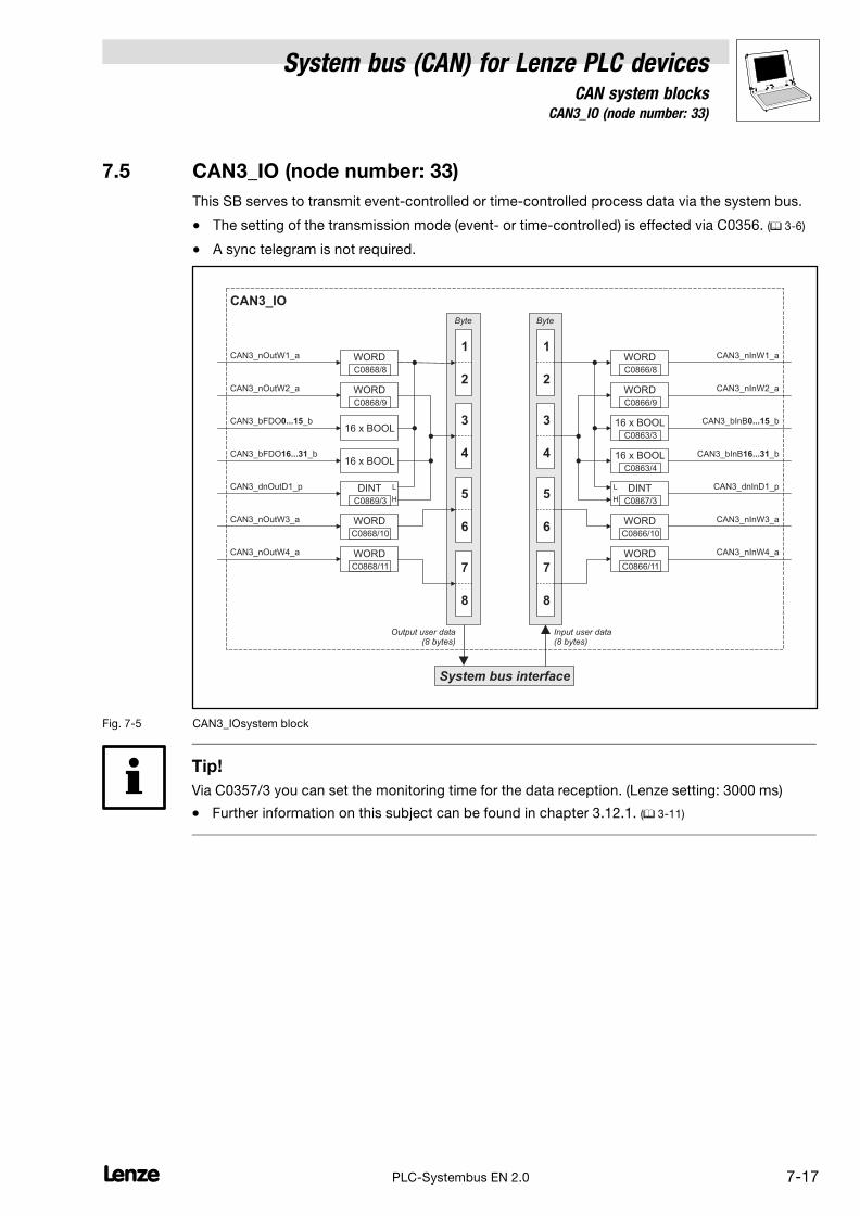
System bus (CAN) for Lenze PLC devicesCAN system blocks
7.5 CAN3_IO (node number: 33)
7−17L PLC−Systembus EN 2.0
7.5 CAN3_IO (node number: 33)
This SB serves to transmit event−controlled or time−controlled process data via the system bus.
� The setting of the transmission mode (event− or time−controlled) is effected via C0356. (� 3−6)
� A sync telegram is not required.
CAN3_nInW1_a
CAN3_nInW2_a
CAN3_bInB _b0...15
CAN3_bInB _b16...31
System bus interface
Byte
7
8
5
6
3
4
1
2
Byte
7
8
5
6
3
4
1
2
CAN3_nOutW1_a
CAN3_nOutW2_a
CAN3_nOutW3_a
CAN3_bFDO _b16...31
CAN3_dnOutD1_p
CAN3_IO
DINT
WORD
WORD
WORD
16 x BOOL
DINT
Output user data(8 bytes)
Input user data(8 bytes)
L
H
L
H
CAN3_bFDO _b0...1516 x BOOL
CAN3_nOutW4_a WORD
WORD
WORD
16 x BOOL
16 x BOOL
CAN3_nInW3_a
CAN3_nInW4_a
WORD
WORD
CAN3_dnInD1_p
C0868/8
C0868/9
C0869/3
C0868/10
C0868/11
C0866/8
C0866/9
C0863/3
C0863/4
C0867/3
C0866/10
C0866/11
Fig. 7−5 CAN3_IOsystem block
Tip!
Via C0357/3 you can set the monitoring time for the data reception. (Lenze setting: 3000 ms)
� Further information on this subject can be found in chapter 3.12.1. (� 3−11)

7.5 CAN3_IO (node number: 33)
System bus (CAN) for Lenze PLC devicesCAN system blocks
7−18 LPLC−Systembus EN 2.0
7.5.1 Inputs_CAN3
Variable Data type Signal type Address Display code Displayformat
Notes
CAN3_nInW1_aInteger Analog
%IW33.0 C0866/8dec [%]
CAN3_nInW2_a %IW33.1 C0866/9
CAN3_bInB0_b
Bool Binary
%IX33.0.0
hex
... ... C0863/5
CAN3_bInB15_b %IX33.0.15
CAN3_bInB16_b %IX33.1.0
... ... C0863/6
CAN3_bInB31_b %IX33.1.15
CAN3_dnInD1_p Double integer Position %ID33.0 C0867/3 dec [inc]
CAN3_nInW3_aInteger Analog
%IW33.2 C0866/10dec [%]
CAN3_nInW4_a %IW33.3 C0866/11
7.5.2 Outputs_CAN3
Variable Data type Signal type Address Display code Displayformat
Notes
CAN3_nOutW1_aInteger Analog
%QW33.0 C0868/8dec [%]
CAN3_nOutW2_a %QW33.1 C0868/9
CAN3_bFDO0_b
Bool Binary
%QX33.0.0
C0151/3 hexDisplay code in hex
as double word
... ...
CAN3_bFDO15_b %QX33.0.15
CAN3_bFDO16_b %QX33.1.0
... ...
CAN3_bFDO31_b %QX33.1.15
CAN3_dnOutD1_p Double integer Position %QD33.0 C0869/3 dec [inc]
CAN3_nOutW3_aInteger Analog
%QW33.2 C0868/10dec [%]
CAN3_nOutW4_a %QW33.3 C0868/11
7.5.3 Process data telegram
The process data telegram consists of an identifier and 8 bytes of user data.
11bit 8 bytes user data
Identifier Byte 1 Byte 2 Byte 3 Byte 4 Byte 5 Byte 6 Byte 7 Byte 8
Information on the identifier can be found in chapter 2.4.1. (� 2−3)

System bus (CAN) for Lenze PLC devicesCAN system blocks
7.5 CAN3_IO (node number: 33)
7−19L PLC−Systembus EN 2.0
7.5.4 Assignment of the user data to variables
Several variables of different data types are assigned to the user data to be transmitted and received.Thus, the data in the PLC program can be optionally interpreted as:
� binary information (1 bit)
� status word/quasi−analog value (16 bit)
� angle information (32 bit)
Variables for user data to be transmitted
User data Assigned variables
Byte Bit Variable (1 bit) Variable (16 bit) Variable (32 bit)
1 0
...
7
CAN3_bFDO0_b
...
CAN3_bFDO7_bCAN3_nOutW1_a
CAN3_dnOutD1_p
2 0
...
7
CAN3_bFDO8_b
...
CAN3_bFDO15_b
3 0
...
7
CAN3_bFDO16_b
...
CAN3_bFDO23_bCAN3_nOutW2_a
4 0
...
7
CAN3_bFDO24_b
...
CAN3_bFDO31_b
5 0...7CAN3_nOutW3_a
6 0...7
7 0...7CAN3_nOutW4_a
8 0...7
Note!
Avoid simultaneous overwriting via different variable types to ensure data consistency.
For instance, if you want to write bytes 1 and 2, only use the variable CAN3_dnOutD1_p,CAN3_nOutW1_a, or only the variables CAN3_bFDO0_b ... CAN3_bFDO15_b for this purpose!
Variables for received user data
User data Assigned variables
Byte Bit Variable (1 bit) Variable (16 bit) Variable (32 bit)
1 0
...
7
CAN3_bInB0_b
...
CAN3_bInB7_bCAN3_nInW1_a
CAN3_dnInD1_p
2 0
...
7
CAN3_bInB8_b
...
CAN3_bInB15_b
3 0
...
7
CAN3_bInB16_b
...
CAN3_bInB23_bCAN3_nInW2_a
4 0
...
7
CAN3_bInB24_b
...
CAN3_bInB31_b
5 0...7CAN3_nInW3_a
6 0...7
7 0...7CAN3_nInW4_a
8 0...7

7.6 CAN_Management (node number: 101)
System bus (CAN) for Lenze PLC devicesCAN system blocks
7−20 LPLC−Systembus EN 2.0
7.6 CAN_Management (node number: 101)
By using this SB
� a reset node can be activated, e. g. to accept changes with regard to the baud rate andaddressings.
� Communication error, Bus−off state, and further states can be processed in the PLCprogram.
� the instant of transmission of CAN2_OUT and CAN3_OUT can be influenced.
CAN_bResetNode_b
CAN_Management
C0358
CAN2_OUT
CAN_bCe2CommErrCanIn2_b
CAN_ResetNode
CAN_bTxCan2Synchronized_b
CAN1_INCommunication error
CAN2_INCommunication error
CAN3_INCommunication error
CANBus off state
CAN_bCe1CommErrCanIn1_b
CAN_bCe3CommErrCanIn3_b
CAN_bCe4BusOffState_b
CAN_SYNC
CAN3_OUTCAN_bTxCan3Synchronized_b
CAN_SYNC
1
CANNode address (C0350)
CANState (C0359)
CAN_byNodeAddress
CAN_byState
CAN_bFreePdoTxBufferOverflow_bFree PDO Txbuffer overflow
Free PDO Rxoverflow
Overrun life time
CAN_bFreePdoRxOverflow_b
CAN_bOverrunLifeTime_b
Fig. 7−6 CAN_Management system block
Note!
The process image for this SB is generated in a fixed system task (interval: 1 ms).
7.6.1 Inputs_CAN_Management
Variable Data type Signal type Address Displaycode
Displayformat
Notes
CAN_bCe1CommErrCanIn1_b
Bool Binary
%IX101.0.0
− −
CAN1_IN communication error
CAN_bCe2CommErrCanIn1_b %IX101.0.1 CAN2_IN communication error
CAN_bCe3CommErrCanIn1_b %IX101.0.2 CAN3_IN communication error
CAN_bCe4BusOffState_b %IX101.0.3 CAN bus "off state" recognised
CAN_bFreePdoTxBufferOverflow_b %IX101.0.4 Transmit request memory overflow
CAN_bFreePdoRxOverflow_b %IX101.0.5 Receive memory overflow
CAN_bOverrunLifeTime_b %IX101.0.6 "Node life time" exceeded
CAN_byNodeAddressByte −
%IB101.2 C0350 − CAN mode address
CAN_byState %IB101.3 C0359 − CAN status

System bus (CAN) for Lenze PLC devicesCAN system blocks
7.6 CAN_Management (node number: 101)
7−21L PLC−Systembus EN 2.0
7.6.2 Outputs_CAN_Management
Variable Data type Signal type Address Displaycode
Displayformat
Notes
CAN_bResetNode_b
Bool Binary
%QX101.0.0
− −
Carry out reset node of the PLC
CAN_bTxCan2Synchronized_b %QX101.0.1 Transmit CAN2_OUT with synctelegram.
CAN_bTxCan3Synchronized_b %QX101.0.2 Transmit CAN3_OUT with synctelegram.
Note!
If CAN_bTxCan2Synchronized_b and/or CAN_bTxCan3Synchronized_b are integrated, it is requiredto configure the device as sync transmitter. The data are transmitted immediately after the syncsignal is sent.
7.6.3 Activating a reset node
A reset node is activated by setting CAN_bResetNode_b to TRUE or C0358 = 1.
Tip!
Even if the CAN_Management SB has not been assigned to the control configuration, a reset nodecan be activated via C0358. (� 3−8)
7.6.4 Defining the instant of transmission for CAN2_OUT/CAN3_OUT
Via CAN_bTxCan2Synchonized_b and CAN_bTxCan3Synchonized_b you define the instant oftransmission for the CAN objects CAN2_OUT and CAN3_OUT:
� FALSE: Data from CAN2_OUT/CAN3_OUT are sent at the end of the process image.
� TRUE: Data from CAN2_OUT/CAN3_OUT are sent to sync.
– The identifiers for the sync transmission C0369 and reception telegram can be set viaC0367/C0368.
– The sync Tx time can be set via C0369.
– Detailed information on this can be found in the description of the CAN_Syncronization SB.(� 7−23)

7.6 CAN_Management (node number: 101)
System bus (CAN) for Lenze PLC devicesCAN system blocks
7−22 LPLC−Systembus EN 2.0
7.6.5 Status messages
The CAN_Management SB provides different status messages which can be processed in the PLCprogram:
Variable Description
CAN_bCe1CommErrCanIn1_b TRUE CAN1_IN communication error
CAN_bCe2CommErrCanIn1_b TRUE CAN2_IN communication error
CAN_bCe3CommErrCanIn1_b TRUE CAN3_IN communication error
CAN_bCe4BusOffState_b TRUE CAN bus "off state" recognised
CAN_bFreePdoTxBufferOverflow_b Free CAN objects
TRUE Overflow of send order memory
� See L_CanPdoTransmit FB. (� 10−8)
CAN_bFreePdoRxOverflow_b Free CAN objects
TRUE Overflow of the receive memory
� See L_CanPdoReceive FB. (� 10−12)
CAN_bOverrunLifeTime_b CAN"Node guarding" monitoring mechanism
TRUE The "Node life time" has been exceeded
� See chapter 2.10, "monitoring mechanisms". (� 2−21)
CAN_byNodeAddress 1...63 CAN node address (� 3−3)
CAN_byState Operating status of the system bus
1 Operational
2 Pre−operational
3 Warning
4 Bus−off

System bus (CAN) for Lenze PLC devicesCAN system blocks
7.7 CAN_Synchronization (node number: 102)
7−23L PLC−Systembus EN 2.0
7.7 CAN_Synchronization (node number: 102)
This SB can be used to synchronise the internal time base of the controller to the instant of receptionof the sync telegram or of a terminal signal. Thus, the start of cyclic and time−controlled internalprocesses (e. g. data transfer from tasks to the DCTRL function block) is effected in a synchronousmanner for all controllers involved in the synchronisation.
CAN_bSyncForInterpolator_b
CAN_Synchronization
CAN_bResetSyncForInterpolartor_b
CAN_nSyncDeviation
CAN_bSyncInsideWindow_b
2
1Sync telegram
SyncControl
C1121
C1123C1122
C0369C0366C0363
C1120
C0367C0368
Sync signal
0Off
Fig. 7−7 CAN_Synchronizationsystem block
Variable Data type Signal type Address Displaycode
Displayformat
Notes
CAN_bSyncInsideWindow_b
Bool Binary
%IX102.0.0
− −
TRUE:
Sync telegram/signal within thetime slot (C1123)
FALSE:
� Exit synchronicity
� No sync telegram/signal
� Time slot (C1123) too small
CAN_bSyncForInterpolator_b %IX102.0.1 TRUE:
Sync telegram/signal recognised
CAN_nSyncDeviation Integer − %IX102.1 Current sync deviation
CAN_bResetSyncForInterpolator_b
Bool Binary%QX102.0.0 TRUE:
Reset CAN_bSyncForInterpolator_b
Operating mode
Code LCD Possible settings IMPORTANT
Lenze Selection
[C1120] Sync mode 0 CAN sync. source
0 Off Synchronisation deactivated.
1 Synchronisation via system bus (CAN) Synchronisation by sync telegramvia system bus.
2 Synchronisation via terminal Synchronisation by sync signal viaterminal:
� 9300 Servo PLC: X5/E5
� Drive PLC: X3/I1
� ECSxA: X6/DI1
Axis synchronisation via system bus (CAN)
The system bus transmits both the sync telegram and the process signals.
Example for applications:
� Specification of cyclic, synchronised position setpoint information for multi−axis applicationsvia the system bus.
7.7 CAN_Synchronization (node number: 102)
System bus (CAN) for Lenze PLC devicesCAN system blocks
7−24 LPLC−Systembus EN 2.0
Axis synchronisation via terminal
The transmission paths for the sync signal and the process signals are separated.
� The process signals are applied via a freely selectable input channel (e. g. AIF interface, DFinput).
� The sync signal is injected via terminal:
PLC Terminal for sync signal
9300 Servo PLC X5/E5
Drive PLC X3/I1
ECSxA X6/DI1
Note!
For the synchronisation via terminal, in addition to the SB CAN_Synchronization the SBDIGITAL_IO has to be included in the control configuration of the Drive PLC Developer Studio.
Examples for applications:
� Specification of cyclic, synchronised position setpoint information for multi−axis applicationsvia other bus systems (e. g. INTERBUS).
� Synchronisation of the internal process cycles to higher−level process controls.
Synchronisation time
After mains power−up and the initialisation time of the PLC, an additional period is required forsynchronisation.
The synchronisation time depends on
� the baud rate of the system bus
� the starting time (arrival of the first sync telegram/signal)
� the interval of the sync telegrams/signals
� the sync correction factor (C0363)
� the operating mode (C1120)
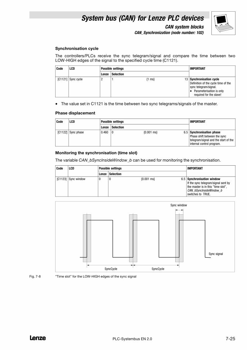
System bus (CAN) for Lenze PLC devicesCAN system blocks
7.7 CAN_Synchronization (node number: 102)
7−25L PLC−Systembus EN 2.0
Synchronisation cycle
The controllers/PLCs receive the sync telegram/signal and compare the time between twoLOW−HIGH edges of the signal to the specified cycle time (C1121).
Code LCD Possible settings IMPORTANT
Lenze Selection
[C1121] Sync cycle 2 1 {1 ms} 13 Synchronisation cycle
Definition of the cycle time of thesync telegram/signal.
� Parameterisation is onlyrequired for the slave!
� The value set in C1121 is the time between two sync telegrams/signals of the master.
Phase displacement
Code LCD Possible settings IMPORTANT
Lenze Selection
[C1122] Sync phase 0.460 0 {0.001 ms} 6.5 Synchronisation phase
Phase shift between the synctelegram/signal and the start of theinternal control program.
Monitoring the synchronisation (time slot)
The variable CAN_bSyncInsideWindow_b can be used for monitoring the synchronisation.
Code LCD Possible settings IMPORTANT
Lenze Selection
[C1123] Sync window 0 0 {0.001 ms} 6.5 Synchronisation window
If the sync telegram/signal sent bythe master is in this "time slot",CAN_bSyncInsideWindow_b�switches to �TRUE.
Sync signal
Sync window
SyncCycle SyncCycle
Fig. 7−8 "Time slot" for the LOW−HIGH edges of the sync signal

7.7 CAN_Synchronization (node number: 102)
System bus (CAN) for Lenze PLC devicesCAN system blocks
7−26 LPLC−Systembus EN 2.0
Tip!
A jitter* up to ±200 �s on the LOW−HIGH edges of the sync signal is permissible. The extent of thejitter has an effect on the parameter setting of the "time slot".
* Jitter refers to the phase shiftings and therefore to the periodic changes of signal frequencies. Theyare variations of fixed points in time (e. g. the time of the transition from one signal amplitude toanother) of a digital signal. Jitter particularly occurs with high frequencies and can result in datalosses.
Correction value of the phase controller
Code LCD Possible settings IMPORTANT
Lenze Selection
C0363 Sync corr 1 9300 Servo PLC: Drive PLC:
1 0.2 �s/ms 0.4 �s/ms
2 0.4 �s/ms 0.8 �s/ms
3 0.6 �s/ms 1.2 �s/ms
4 0.8 �s/ms 1.6 �s/ms
5 1.0 �s/ms 2.0 �s/ms
CAN sync correction increment
Alter the correction value untilCAN_nSyncDeviation has reached aminimum.
CAN sync response
Code LCD Possible settings IMPORTANT
Lenze Selection
C0366 Sync response 1 CAN sync response
0 No response No response
1 Response to sync PLC responds to a sync telegramby sending the CAN1_OUT object.
CAN sync identifier
Transmit or receive identifier of the sync telegram
Code LCD Possible settings IMPORTANT
Lenze Selection
C0367 Sync Rx Id 128 1 {1} 256 CAN sync Rx identifier
Receive identifier of the synctelegram.
C0368 Sync Tx Id 128 1 {1} 256 CAN sync Tx identifier
Send identifier of the synctelegram.
CAN sync Tx transmission cycle
Code LCD Possible settings IMPORTANT
Lenze Selection
C0369 Sync Tx time 0 0 {1} 65000
0 = Off
CAN sync transmission telegramcycle
A sync telegram with the identifierof C0368 is sent with the set cycletime.

System bus (CAN) for Lenze PLC devicesCAN system blocks
7.7 CAN_Synchronization (node number: 102)
7−27L PLC−Systembus EN 2.0
Configuration example: synchronisation via system bus (CAN)
When carrying out the commissioning, observe the following sequence:
Location Step Information
All devices 1. Commission controller/PLC and system bus.
2. Inhibit controller/PLC.
DDS 3. Integrate CAN_Synchronization SB into the control configuration.
Slave devices 4. Connect CAN_bSyncInsideWindow_b to a digital output.
5. C1120 = 1 Synchronisation by sync telegram via system busactive.
6. C0366 = 1 (Lenze setting) CAN sync response:
Slave devices respond to sync telegram.
Master 7. Define order of the telegrams (identifiers):
1. Send new setpoint to all slaves
2. Send sync telegram
3. Receive response of all slaves
8. Start communication / send sync telegrams.
Slave devices 9. Read C0362 from the master. Query cycle time of the sync telegram from themaster.
10. Set C1121 in accordance with C0362 from the master. Adjust interval of the sync telegrams to bereceived to the cycle time of the master.
11. Set C1123. Set optimum size for the "time slot".
� If the sync signal "jitters" heavily, increase"time slot".
12. Enable controller/PLC via the signal CAN_bSyncInsideWindow_bapplied to the digital output.
Monitor the synchronisation.
� If CAN_bSyncInsideWindow_b = TRUE, enablecontroller/PLC.
Configuration example: synchronisation via terminal
When carrying out the commissioning, observe the following sequence:
Location Step Information
All devices 1. Commission controller/PLC and system bus.
2. Inhibit controller/PLC.
DDS 3. Integrate CAN_Synchronization SB into the control configuration.
Slave devices 4. Connect CAN_bSyncInsideWindow_b to a digital output.
5. Apply sync signal of the master to terminal. 9300 Servo PLC: terminal X5/E5
Drive PLC: terminal X3/I1
ECSxA: X6/DI1
Slave devices 6. C1120 = 2 Synchronisation by sync signal via terminal active.
Slave devices 7. C0366 = 1 (Lenze setting) CAN sync response:
Slave devices respond to sync telegram.
Master 8. Start communication, send sync telegrams.
Slave devices 9. Read C0362 from the master. Query cycle time of the sync signal from themaster.
10. Set C1121 in accordance with C0362 from the master. Adjust interval of the sync signals to be receivedto the cycle time of the master.
11. Set C1123. Set optimum size for the "time slot".
� If the sync signal "jitters" heavily, increase"time slot".
12. Enable controller/PLC via the signal CAN_bSyncInsideWindow_bapplied to the digital output.
Monitor the synchronisation.
� If CAN_bSyncInsideWindow_b = TRUE, enablecontroller/PLC.

7.7 CAN_Synchronization (node number: 102)
System bus (CAN) for Lenze PLC devicesCAN system blocks
7−28 LPLC−Systembus EN 2.0

System bus (CAN) for Lenze PLC devicesFIF−CAN system blocks
8.1 FIF_CAN1_IO (node number: 34)
8−1L PLC−Systembus EN 2.0
8 FIF−CAN system blocks (only Drive PLC)
8.1 FIF_CAN1_IO (node number: 34)
This SB serves to the transmission of cyclic process data via the function interface of the Drive PLC.
� For the transmission a sync telegram is required, which has to be generated by a differentnode. (� 2−9)
FIF_CAN1_nInW0_a
FIF_CAN1_nInW1_a
FIF_CAN1_bInB _b0...15
FIF_CAN1_bInB _b16...31
FIF System bus interface
Byte
7
8
5
6
3
4
1
2
Byte
7
8
5
6
3
4
1
2
FIF_CAN1_nOutW0_a
FIF_CAN1_nOutW1_a
FIF_CAN1_nOutW2_a
FIF_CAN1_bFDO _b16...31
FIF_CAN1_dnOutD1_p
FIF_CAN1_IO
DINT
WORD
WORD
WORD
16 x BOOL
DINT
Output user data(8 bytes)
Input user data(8 bytes)
L
H
L
H
FIF_CAN1_bFDO _b0...1516 x BOOL
FIF_CAN1_nOutW3_a WORD
FIF_CAN1_nInW2_a
FIF_CAN1_nInW3_a
FIF_CAN1_dnInD1_p
C2493/1
C2493/2
C2493/3
FIF_CAN1_bFDO _b32...4716 x BOOL
FIF_CAN1_bFDO _b48...6316 x BOOL
WORD
WORD
16 x BOOL
16 x BOOL
WORD
C2492/1
C2492/2
C2492/3
16 x BOOL
16 x BOOL
WORD
C2491/1
FIF_CAN1_bInB _b32...47
FIF_CAN1_bInB _b48...63
C2491/2
Fig. 8−1 FIF_CAN1_IO system block

8.1 FIF_CAN1_IO (node number: 34)
System bus (CAN) for Lenze PLC devicesFIF−CAN system blocks
8−2 LPLC−Systembus EN 2.0
8.1.1 FIF_Inputs_CAN1
Variable Data type Signal type Address Display code Displayformat
Notes
FIF_CAN1_nInW0_a Integer Analog %IW34.0
FIF_CAN1_bInB0_b %IX34.0.0
... Bool Binary ... C2491/1 hex
FIF_CAN1_bInB15_b %IX34.0.15
FIF_CAN1_nInW1_a Integer Analog %IW34.1 C2492/1 dec [%]
FIF_CAN1_bInB16_b %IX34.1.0
... Bool Binary ... C2491/2 hex
FIF_CAN1_bInB31_b %IX34.1.15
FIF_CAN1_nInW2_a Integer Analog %IW34.2 C2492/2 dec [%]
FIF_CAN1_bInB32_b %IX34.2.0
... Bool Binary ...
FIF_CAN1_bInB47_b %IX34.2.15
FIF_CAN1_nInW3_a Integer Analog %IW34.3 C2492/3 dec [%]
FIF_CAN1_bInB48_b %IX34.3.0
... Bool Binary ...
FIF_CAN1_bInB63_b %IX34.3.15
FIF_CAN1_dnInD1_p Double integer Position %ID34.1
8.1.2 FIF_Outputs_CAN1
Variable Data type Signal type Address Display code Displayformat
Notes
FIF_CAN1_nOutW0_a Integer Analog %QW34.0 − −
FIF_CAN1_bFDO0_b
Bool Binary
%QX34.0.0
− −.. ..
FIF_CAN1_bFDO15_b %QX34.0.15
FIF_CAN1_nOutW1_a Integer Analog %QW34.1 C2493/1 dec [%]
FIF_CAN1_bFDO16_b
Bool Binary
%QX34.1.0
− −.. ..
FIF_CAN1_bFDO31_b %QX34.1.15
FIF_CAN1_nOutW2_a Integer Analog %QW34.2 C2493/2 dec [%]
FIF_CAN1_bFDO32_b
Bool Binary
%QX34.2.0
− −.. ..
FIF_CAN1_bFDO47_b %QX34.2.15
FIF_CAN1_nOutW3_a Integer Analog %QW34.3 C2493/3 dec [%]
FIF_CAN1_bFDO48_b
Bool Binary
%QX34.3.0
− −.. ..
FIF_CAN1_bFDO63_b %QX34.3.15
FIF_CAN1_dnOutD1_p Double integer Position %QD34.1 − −

System bus (CAN) for Lenze PLC devicesFIF−CAN system blocks
8.1 FIF_CAN1_IO (node number: 34)
8−3L PLC−Systembus EN 2.0
8.1.3 Process data telegram
The process data telegram consists of an identifier and 8 bytes of user data.
11bit 8 bytes user data
Identifier Byte 1 Byte 2 Byte 3 Byte 4 Byte 5 Byte 6 Byte 7 Byte 8
Information on the identifier can be found in chapter 2.4.1. (� 2−3)
8.1.4 Assignment of the user data to variables
Several variables of different data types are assigned to the user data to be transmitted and received.Thus, the data in the PLC program can be optionally interpreted as:
� binary information (1 bit)
� status word/quasi−analog value (16 bit)
� angle information (32 bit)
Variables for user data to be transmitted
User data Assigned variables
Byte Bit Variable (1 bit) Variable (16 bit) Variable (32 bit)
1 0
...
7
FIF_CAN1_bFDO0_b
...
FIF_CAN1_bFDO7_bFIF_CAN1_nOutW0_a
2 0
...
7
FIF_CAN1_bFDO8_b
...
FIF_CAN1_bFDO15_b
3 0
...
7
FIF_CAN1_bFDO16_b
...
FIF_CAN1_bFDO23_bFIF_CAN1_nOutW1_a
4 0
...
7
FIF_CAN1_bFDO24_b
...
FIF_CAN1_bFDO31_b
5 0
...
7
FIF_CAN1_bFDO32_b
...
FIF_CAN1_bFDO39_bFIF_CAN1_nOutW2_a
FIF_CAN1_dnOutD1_p
6 0
...
7
FIF_CAN1_bFDO40_b
...
FIF_CAN1_bFDO47_b
7 0
...
7
FIF_CAN1_bFDO48_b
...
FIF_CAN1_bFDO55_bFIF_CAN1_nOutW3_a
8 0
...
7
FIF_CAN1_bFDO56_b
...
FIF_CAN1_bFDO63_b
Note!
Avoid simultaneous overwriting via different variable types to ensure data consistency.
For instance, if you want to write the bytes 5 and 6, only use the variable FIF_CAN1_dnOutD1_p,FIF_CAN1_nOutW2_a, or only the variables FIF_CAN1_bFDO32_b ... FIF_CAN1_bFDO47_b for thispurpose!

8.1 FIF_CAN1_IO (node number: 34)
System bus (CAN) for Lenze PLC devicesFIF−CAN system blocks
8−4 LPLC−Systembus EN 2.0
Variables for received user data
User data Assigned variables
Byte Bit Variable (1 bit) Variable (16 bit) Variable (32 bit)
1 0
...
7
FIF_CAN1_bInB0_b
...
FIF_CAN1_bInB7_bFIF_CAN1_nInW0_a
2 0
...
7
FIF_CAN1_bInB8_b
...
FIF_CAN1_bInB15_b
3 0
...
7
FIF_CAN1_bInB16_b
...
FIF_CAN1_bInB23_bFIF_CAN1_nInW1_a
4 0
...
7
FIF_CAN1_bInB24_b
...
FIF_CAN1_bInB31_b
5 0
...
7
FIF_CAN1_bInB32_b
...
FIF_CAN1_bInB39_bFIF_CAN1_nInW2_a
FIF_CAN1_dnInD1_p
6 0
...
7
FIF_CAN1_bInB40_b
...
FIF_CAN1_bInB47_b
7 0
...
7
FIF_CAN1_bInB48_b
...
FIF_CAN1_bInB55_bFIF_CAN1_nInW3_a
8 0
...
7
FIF_CAN1_bInB56_b
...
FIF_CAN1_bInB63_b
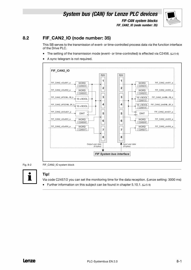
System bus (CAN) for Lenze PLC devicesFIF−CAN system blocks
8.2 FIF_CAN2_IO (node number: 35)
8−1L PLC−Systembus EN 2.0
8.2 FIF_CAN2_IO (node number: 35)
This SB serves to the transmission of event− or time−controlled process data via the function interfaceof the Drive PLC.
� The setting of the transmission mode (event− or time−controlled) is effected via C2456. (� 5−6)
� A sync telegram is not required.
FIF_CAN2_nInW1_a
FIF_CAN2_nInW2_a
FIF_CAN2_bInB _b0...15
FIF_CAN2_bInB _b16...31
FIF System bus interface
Byte
7
8
5
6
3
4
1
2
Byte
7
8
5
6
3
4
1
2
FIF_CAN2_nOutW1_a
FIF_CAN2_nOutW2_a
FIF_CAN2_nOutW3_a
FIF_CAN2_bFDO _b16...31
FIF_CAN2_dnOutD1_p
FIF_CAN2_IO
DINT
WORD
WORD
WORD
16 x BOOL
DINT
Output user data(8 bytes)
Input user data(8 bytes)
L
H
L
H
FIF_CAN2_bFDO _b0...1516 x BOOL
FIF_CAN2_nOutW4_a WORD
WORD
WORD
16 x BOOL
16 x BOOL
FIF_CAN2_nInW3_a
FIF_CAN2_nInW4_a
WORD
WORD
FIF_CAN2_dnInD1_p
C2493/4
C2493/5
C2493/6
C2493/7
C2492/4
C2492/5
C2491/3
C2491/4
C2492/6
C2492/7
Fig. 8−2 FIF_CAN2_IO system block
Tip!
Via code C2457/2 you can set the monitoring time for the data reception. (Lenze setting: 3000 ms)
� Further information on this subject can be found in chapter 5.10.1. (� 5−9)

8.2 FIF_CAN2_IO (node number: 35)
System bus (CAN) for Lenze PLC devicesFIF−CAN system blocks
8−2 LPLC−Systembus EN 2.0
8.2.1 FIF_Inputs_CAN2
Variable Data type Signal type Address Display code Displayformat
Notes
FIF_CAN2_nInW1_aInteger Analog
%IW35.0 C2492/4dec [%]
FIF_CAN2_nInW2_a %IW35.1 C2492/5
FIF_CAN2_bInB0_b
Bool Binary
%IX35.0.0
hex
... ... C2491/3
FIF_CAN2_bInB15_b %IX35.0.15
FIF_CAN2_bInB16_b %IX35.1.0
... ... C2491/4
FIF_CAN2_bInB31_b %IX35.1.15
FIF_CAN2_dnInD1_p Double integer Position %ID35.0 − −
FIF_CAN2_nInW3_aInteger Analog
%IW35.2 C2492/6dec [%]
FIF_CAN2_nInW4_a %IW35.3 C2492/7
8.2.2 FIF_Outputs_CAN2
Variable Data type Signal type Address Display code Displayformat
Notes
FIF_CAN2_nOutW1_aInteger Analog
%QW35.0 C2493/4dec [%]
FIF_CAN2_nOutW2_a %QW35.1 C2493/5
FIF_CAN2_bFDO0_b
Bool Binary
%QX35.0.0
− −
... ...
FIF_CAN2_bFDO15_b %QX35.0.15
FIF_CAN2_bFDO16_b %QX35.1.0
... ...
FIF_CAN2_bFDO31_b %QX35.1.15
FIF_CAN2_dnOutD1_p Double integer Position %QD35.0 − −
FIF_CAN2_nOutW3_aInteger Analog
%QW35.2 C2493/6dec [%]
FIF_CAN2_nOutW4_a %QW35.3 C2493/7
8.2.3 Process data telegram
The process data telegram consists of an identifier and 8 bytes of user data.
11bit 8 bytes user data
Identifier Byte 1 Byte 2 Byte 3 Byte 4 Byte 5 Byte 6 Byte 7 Byte 8
Information on the identifier can be found in chapter 2.4.1. (� 2−3)

System bus (CAN) for Lenze PLC devicesFIF−CAN system blocks
8.2 FIF_CAN2_IO (node number: 35)
8−3L PLC−Systembus EN 2.0
8.2.4 Assignment of the user data to variables
Several variables of different data types are assigned to the user data to be transmitted and received.Thus, the data in the PLC program can be optionally interpreted as:
� binary information (1 bit)
� status word/quasi−analog value (16 bit)
� angle information (32 bit)
Variables for user data to be transmitted
User data Assigned variables
Byte Bit Variable (1 bit) Variable (16 bit) Variable (32 bit)
1 0
...
7
FIF_CAN2_bFDO0_b
...
FIF_CAN2_bFDO7_bFIF_CAN2_nOutW1_a
FIF_CAN2_dnOutD1_p
2 0
...
7
FIF_CAN2_bFDO8_b
...
FIF_CAN2_bFDO15_b
3 0
...
7
FIF_CAN2_bFDO16_b
...
FIF_CAN2_bFDO23_bFIF_CAN2_nOutW2_a
4 0
...
7
FIF_CAN2_bFDO24_b
...
FIF_CAN2_bFDO31_b
5 0...7FIF_CAN2_nOutW3_a
6 0...7
7 0...7FIF_CAN2_nOutW4_a
8 0...7
Note!
Avoid simultaneous overwriting via different variable types to ensure data consistency.
For instance, if you want to write the bytes 1 and 2, only use the variable FIF_CAN2_dnOutD1_p,FIF_CAN2_nOutW1_a, or only the variables FIF_CAN2_bFDO0_b ... FIF_CAN2_bFDO15_b for thispurpose!
Variables for received user data
User data Assigned variables
Byte Bit Variable (1 bit) Variable (16 bit) Variable (32 bit)
1 0
...
7
FIF_CAN2_bInB0_b
...
FIF_CAN2_bInB7_bFIF_CAN2_nInW1_a
FIF_CAN2_dnInD1_p
2 0
...
7
FIF_CAN2_bInB8_b
...
FIF_CAN2_bInB15_b
3 0
...
7
FIF_CAN2_bInB16_b
...
FIF_CAN2_bInB23_bFIF_CAN2_nInW2_a
4 0
...
7
FIF_CAN2_bInB24_b
...
FIF_CAN2_bInB31_b
5 0...7FIF_CAN2_nInW3_a
6 0...7
7 0...7FIF_CAN2_nInW4_a
8 0...7

System bus (CAN) for Lenze PLC devicesFIF−CAN system blocks
8.3 FIF_CAN3_IO (node number: 36)
8−1L PLC−Systembus EN 2.0
8.3 FIF_CAN3_IO (node number: 36)
This SB serves to the transmission of event− or time−controlled process data via the function interfaceof the Drive PLC.
� The setting of the transmission mode (event− or time−controlled) is effected via C2456. (� 5−6)
� A sync telegram is not required.
FIF_CAN3_nInW1_a
FIF_CAN3_nInW2_a
FIF_CAN3_bInB _b0...15
FIF_CAN3_bInB _b16...31
FIF System bus interface
Byte
7
8
5
6
3
4
1
2
Byte
7
8
5
6
3
4
1
2
FIF_CAN3_nOutW1_a
FIF_CAN3_nOutW2_a
FIF_CAN3_nOutW3_a
FIF_CAN3_bFDO _b16...31
FIF_CAN3_dnOutD1_p
FIF_CAN3_IO
DINT
WORD
WORD
WORD
16 x BOOL
DINT
Output user data(8 bytes)
Input user data(8 bytes)
L
H
L
H
FIF_CAN3_bFDO _b0...1516 x BOOL
FIF_CAN3_nOutW4_a WORD
WORD
WORD
16 x BOOL
16 x BOOL
FIF_CAN3_nInW3_a
FIF_CAN3_nInW4_a
WORD
WORD
FIF_CAN3_dnInD1_p
C2493/8
C2493/9
C2493/10
C2493/11
C2492/8
C2492/9
C2492/5
C2491/6
C2492/10
C2492/11
Fig. 8−3 FIF_CAN3_IO system block
Tip!
Via code C2457/3 you can set the monitoring time for the data reception. (Lenze setting: 3000 ms)
� Further information on this subject can be found in chapter 5.10.1. (� 5−9)

8.3 FIF_CAN3_IO (node number: 36)
System bus (CAN) for Lenze PLC devicesFIF−CAN system blocks
8−2 LPLC−Systembus EN 2.0
8.3.1 FIF_Inputs_CAN3
Variable Data type Signal type Address Display code Displayformat
Notes
FIF_CAN3_nInW1_aInteger Analog
%IW36.0 C2492/8dec [%]
FIF_CAN3_nInW2_a %IW36.1 C2492/9
FIF_CAN3_bInB0_b
Bool Binary
%IX36.0.0
hex
... ... C2491/5
FIF_CAN3_bInB15_b %IX36.0.15
FIF_CAN3_bInB16_b %IX36.1.0
... ... C2491/6
FIF_CAN3_bInB31_b %IX36.1.15
FIF_CAN3_dnInD1_p Double integer Position %ID36.0 − −
FIF_CAN3_nInW3_aInteger Analog
%IW36.2 C2492/10dec [%]
FIF_CAN3_nInW4_a %IW36.3 C2492/11
8.3.2 FIF_Outputs_CAN3
Variable Data type Signal type Address Display code Displayformat
Notes
FIF_CAN3_nOutW1_aInteger Analog
%QW36.0 C2493/8dec [%]
FIF_CAN3_nOutW2_a %QW36.1 C2493/9
FIF_CAN3_bFDO0_b
Bool Binary
%QX36.0.0
− −
... ...
FIF_CAN3_bFDO15_b %QX36.0.15
FIF_CAN3_bFDO16_b %QX36.1.0
... ...
FIF_CAN3_bFDO31_b %QX36.1.15
FIF_CAN3_dnOutD1_p Double integer Position %QD36.0 − −
FIF_CAN3_nOutW3_aInteger Analog
%QW36.2 C2493/10dec [%]
FIF_CAN3_nOutW4_a %QW36.3 C2493/11
8.3.3 Process data telegram
The process data telegram consists of an identifier and 8 bytes of user data.
11bit 8 bytes user data
Identifier Byte 1 Byte 2 Byte 3 Byte 4 Byte 5 Byte 6 Byte 7 Byte 8
Information on the identifier can be found in chapter 2.4.1. (� 2−3)

System bus (CAN) for Lenze PLC devicesFIF−CAN system blocks
8.3 FIF_CAN3_IO (node number: 36)
8−3L PLC−Systembus EN 2.0
8.3.4 Assignment of the user data to variables
Several variables of different data types are assigned to the user data to be transmitted and received.Thus, the data in the PLC program can be optionally interpreted as:
� binary information (1 bit)
� status word/quasi−analog value (16 bit)
� angle information (32 bit)
Variables for user data to be transmitted
User data Assigned variables
Byte Bit Variable (1 bit) Variable (16 bit) Variable (32 bit)
1 0
...
7
FIF_CAN3_bFDO0_b
...
FIF_CAN3_bFDO7_bFIF_CAN3_nOutW1_a
FIF_CAN3_dnOutD1_p
2 0
...
7
FIF_CAN3_bFDO8_b
...
FIF_CAN3_bFDO15_b
3 0
...
7
FIF_CAN3_bFDO16_b
...
FIF_CAN3_bFDO23_bFIF_CAN3_nOutW2_a
4 0
...
7
FIF_CAN3_bFDO24_b
...
FIF_CAN3_bFDO31_b
5 0...7FIF_CAN3_nOutW3_a
6 0...7
7 0...7FIF_CAN3_nOutW4_a
8 0...7
Note!
Avoid simultaneous overwriting via different variable types to ensure data consistency.
For instance, if you want to write the bytes 1 and 2, only use the variable FIF_CAN3_dnOutD1_p,FIF_CAN3_nOutW1_a, or only the variables FIF_CAN3_bFDO0_b ... FIF_CAN3_bFDO15_b for thispurpose!
Variables for received user data
User data Assigned variables
Byte Bit Variable (1 bit) Variable (16 bit) Variable (32 bit)
1 0
...
7
FIF_CAN3_bInB0_b
...
FIF_CAN3_bInB7_bFIF_CAN3_nInW1_a
FIF_CAN3_dnInD1_p
2 0
...
7
FIF_CAN3_bInB8_b
...
FIF_CAN3_bInB15_b
3 0
...
7
FIF_CAN3_bInB16_b
...
FIF_CAN3_bInB23_bFIF_CAN3_nInW2_a
4 0
...
7
FIF_CAN3_bInB24_b
...
FIF_CAN3_bInB31_b
5 0...7FIF_CAN3_nInW3_a
6 0...7
7 0...7FIF_CAN3_nInW4_a
8 0...7
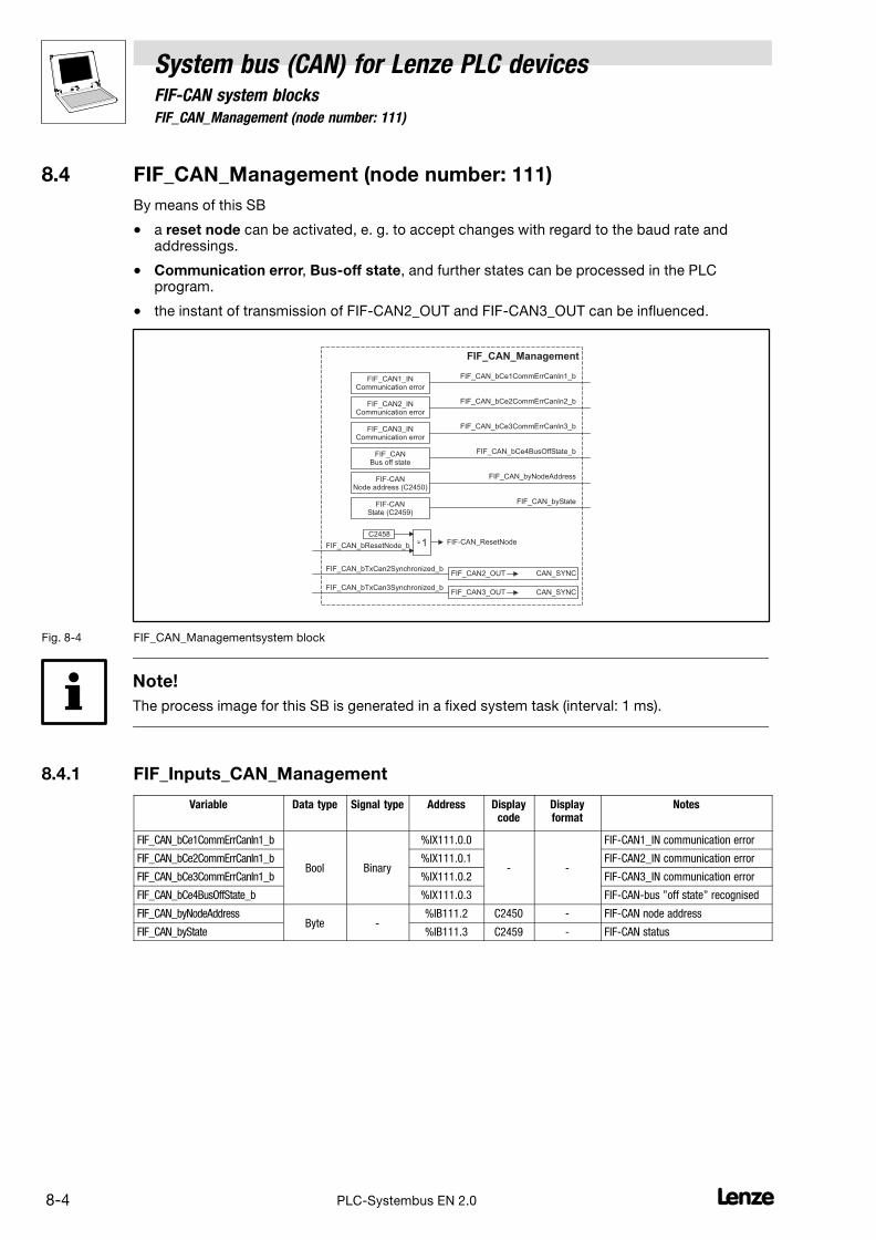
8.4 FIF_CAN_Management (node number: 111)
System bus (CAN) for Lenze PLC devicesFIF−CAN system blocks
8−4 LPLC−Systembus EN 2.0
8.4 FIF_CAN_Management (node number: 111)
By means of this SB
� a reset node can be activated, e. g. to accept changes with regard to the baud rate andaddressings.
� Communication error, Bus−off state, and further states can be processed in the PLCprogram.
� the instant of transmission of FIF−CAN2_OUT and FIF−CAN3_OUT can be influenced.
FIF_CAN_bResetNode_b
FIF_CAN_Management
C2458
FIF_CAN2_OUT
FIF_CAN_bCe2CommErrCanIn2_b
FIF-CAN_ResetNode
FIF_CAN_bTxCan2Synchronized_b
FIF_CAN1_INCommunication error
FIF_CAN2_INCommunication error
FIF_CAN3_INCommunication error
FIF_CANBus off state
FIF_CAN_bCe1CommErrCanIn1_b
FIF_CAN_bCe3CommErrCanIn3_b
FIF_CAN_bCe4BusOffState_b
CAN_SYNC
FIF_CAN3_OUTFIF_CAN_bTxCan3Synchronized_b
CAN_SYNC
1
FIF-CANNode address (C2450)
FIF-CANState (C2459)
FIF_CAN_byNodeAddress
FIF_CAN_byState
Fig. 8−4 FIF_CAN_Managementsystem block
Note!
The process image for this SB is generated in a fixed system task (interval: 1 ms).
8.4.1 FIF_Inputs_CAN_Management
Variable Data type Signal type Address Displaycode
Displayformat
Notes
FIF_CAN_bCe1CommErrCanIn1_b
Bool Binary
%IX111.0.0
− −
FIF−CAN1_IN communication error
FIF_CAN_bCe2CommErrCanIn1_b %IX111.0.1 FIF−CAN2_IN communication error
FIF_CAN_bCe3CommErrCanIn1_b %IX111.0.2 FIF−CAN3_IN communication error
FIF_CAN_bCe4BusOffState_b %IX111.0.3 FIF−CAN−bus "off state" recognised
FIF_CAN_byNodeAddressByte −
%IB111.2 C2450 − FIF−CAN node address
FIF_CAN_byState %IB111.3 C2459 − FIF−CAN status
System bus (CAN) for Lenze PLC devicesFIF−CAN system blocks
8.4 FIF_CAN_Management (node number: 111)
8−5L PLC−Systembus EN 2.0
8.4.2 FIF_Outputs_CAN_Management
Variable Data type Signal type Address Displaycode
Displayformat
Notes
FIF_CAN_bResetNode_b
Bool Binary
%QX111.0.0
− −
Carry out reset node of the FIF−CAN
FIF_CAN_bTxCan2Synchronized_b %QX111.0.1 Transmit FIF−CAN2_OUT with synctelegram.
FIF_CAN_bTxCan3Synchronized_b %QX111.0.2 Transmit FIF−CAN_OUT with synctelegram.
Note!
If FIF_CAN_bTxCan2Synchronized_b and/or FIF_CAN_bTxCan3Synchronized_b are integrated, itis required to configure the device as sync transmitter. The data are transmitted immediately afterthe sync telegram is sent.
8.4.3 Activating a reset node
A reset node can be activated by setting FIF_CAN_bResetNode_b to TRUE or C2458 = 1.
Tip!
Even if the FIF_CAN_Management SB has not been assigned to the control configuration, a resetnode can be activated via C2458. (� 5−8)
8.4.4 Defining the instant of transmission for FIF−CAN2_OUT/FIF−CAN3_OUT
Via FIF_CAN_bTxCan2Synchonized_b and FIF_CAN_bTxCan3Synchonized_b you define theinstant of transmission for the CAN objects FIF−CAN2_OUT and FIF−CAN3_OUT:
� FALSE: Data from FIF−CAN2_OUT/FIF−CAN3_OUT are sent at the end of the process image.
� TRUE: Data from FIF−CAN2_OUT/FIF−CAN3_OUT are sent to sync.
– The identifiers for the sync transmission and reception telegram can be set viaC2467/C2468.
– The sync Tx time can be set via C2469.

8.4 FIF_CAN_Management (node number: 111)
System bus (CAN) for Lenze PLC devicesFIF−CAN system blocks
8−6 LPLC−Systembus EN 2.0
8.4.5 Status messages
The FIF_CAN_Management SB provides different status messages which can be processed in thePLC program:
Variable Description
FIF_CAN_bCe1CommErrCanIn1_b TRUE FIF−CAN1_IN communication error
FIF_CAN_bCe2CommErrCanIn1_b TRUE FIF−CAN2_IN communication error
FIF_CAN_bCe3CommErrCanIn1_b TRUE FIF−CAN3_IN communication error
FIF_CAN_bCe4BusOffState_b TRUE FIF−CAN bus "off state" recognised
FIF_CAN_byNodeAddress 1...63 FIF−CAN node address (� 3−3)
FIF_CAN_byState FIFsystem busoperating status
1 Operational
2 Pre−operational
3 Warning
4 Bus−off

System bus (CAN) for Lenze PLC devicesCAN−AUX system blocks
9.1 CANaux1_IO (node number: 34)
9−1L PLC−Systembus EN 2.0
9 CAN−AUX system blocks (only ECSxA)
9.1 CANaux1_IO (node number: 34)
This SB serves to transmit cyclic process data via the system bus.
� For the transmission a sync telegram is required, which has to be generated by a differentnode. (� 2−9)
CANaux1_nInW0_a
CANaux1_nInW1_a
CANaux1_bInB _b0...15
CANaux1_bInB _b16...31
CAN-AUX System bus interface
Byte
7
8
5
6
3
4
1
2
Byte
7
8
5
6
3
4
1
2
CANaux1_nOutW0_a
CANaux1_nOutW1_a
CANaux1_nOutW2_a
CANaux1_bFDO _b16...31
CANaux1_dnOutD1_p
CANaux1_IO
DINT
WORD
WORD
WORD
16 x BOOL
DINT
Output user data(8 bytes)
Input user data(8 bytes)
L
H
L
H
CANaux1_bFDO _b0...1516 x BOOL
CANaux1_nOutW3_a WORD
CANaux1_nInW2_a
CANaux1_nInW3_a
CANaux1_dnInD1_p
C2493/1
C2493/2
C2493/3
CANaux1_bFDO _b32...4716 x BOOL
CANaux1_bFDO _b48...6316 x BOOL
WORD
WORD
16 x BOOL
16 x BOOL
WORD
C2492/1
C2492/2
C2492/3
16 x BOOL
16 x BOOL
WORD
C2491/1
CANaux1_bInB _b32...47
CANaux1_bInB _b48...63
C2491/2
Fig. 9−1 CANaux1_IOsystem block

9.1 CANaux1_IO (node number: 34)
System bus (CAN) for Lenze PLC devicesCAN−AUX system blocks
9−2 LPLC−Systembus EN 2.0
9.1.1 Inputs_CANaux1
Variable Data type Signal type Address Display code Displayformat
Notes
CANaux1_nInW0_a Integer Analog %IW34.0
CANaux1_bInB0_b %IX34.0.0
... Bool Binary ... C2491/1 hex
CANaux1_bInB15_b %IX34.0.15
CANaux1_nInW1_a Integer Analog %IW34.1 C2492/1 dec [%]
CANaux1_bInB16_b %IX34.1.0
... Bool Binary ... C2491/2 hex
CANaux1_bInB31_b %IX34.1.15
CANaux1_nInW2_a Integer Analog %IW34.2 C2492/2 dec [%]
CANaux1_bInB32_b %IX34.2.0
... Bool Binary ...
CANaux1_bInB47_b %IX34.2.15
CANaux1_nInW3_a Integer Analog %IW34.3 C2492/3 dec [%]
CANaux1_bInB48_b %IX34.3.0
... Bool Binary ...
CANaux1_bInB63_b %IX34.3.15
CANaux1_dnInD1_p Double integer Position %ID34.1
9.1.2 Outputs_CANaux1
Variable Data type Signal type Address Display code Displayformat
Notes
CANaux1_nOutW0_a Integer Analog %QW34.0 − −
CANaux1_bFDO0_b
Bool Binary
%QX34.0.0
− −.. ..
CANaux1_bFDO15_b %QX34.0.15
CANaux1_nOutW1_a Integer Analog %QW34.1 C2493/1 dec [%]
CANaux1_bFDO16_b
Bool Binary
%QX34.1.0
− −.. ..
CANaux1_bFDO31_b %QX34.1.15
CANaux1_nOutW2_a Integer Analog %QW34.2 C2493/2 dec [%]
CANaux1_bFDO32_b
Bool Binary
%QX34.2.0
− −.. ..
CANaux1_bFDO47_b %QX34.2.15
CANaux1_nOutW3_a Integer Analog %QW34.3 C2493/3 dec [%]
CANaux1_bFDO48_b
Bool Binary
%QX34.3.0
− −.. ..
CANaux1_bFDO63_b %QX34.3.15
CANaux1_dnOutD1_p Double integer Position %QD34.1 − −
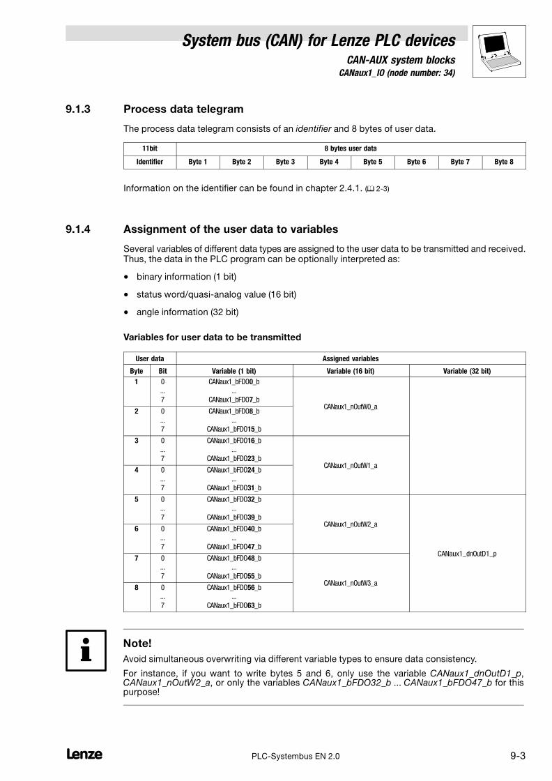
System bus (CAN) for Lenze PLC devicesCAN−AUX system blocks
9.1 CANaux1_IO (node number: 34)
9−3L PLC−Systembus EN 2.0
9.1.3 Process data telegram
The process data telegram consists of an identifier and 8 bytes of user data.
11bit 8 bytes user data
Identifier Byte 1 Byte 2 Byte 3 Byte 4 Byte 5 Byte 6 Byte 7 Byte 8
Information on the identifier can be found in chapter 2.4.1. (� 2−3)
9.1.4 Assignment of the user data to variables
Several variables of different data types are assigned to the user data to be transmitted and received.Thus, the data in the PLC program can be optionally interpreted as:
� binary information (1 bit)
� status word/quasi−analog value (16 bit)
� angle information (32 bit)
Variables for user data to be transmitted
User data Assigned variables
Byte Bit Variable (1 bit) Variable (16 bit) Variable (32 bit)
1 0
...
7
CANaux1_bFDO0_b
...
CANaux1_bFDO7_bCANaux1_nOutW0_a
2 0
...
7
CANaux1_bFDO8_b
...
CANaux1_bFDO15_b
3 0
...
7
CANaux1_bFDO16_b
...
CANaux1_bFDO23_bCANaux1_nOutW1_a
4 0
...
7
CANaux1_bFDO24_b
...
CANaux1_bFDO31_b
5 0
...
7
CANaux1_bFDO32_b
...
CANaux1_bFDO39_bCANaux1_nOutW2_a
CANaux1_dnOutD1_p
6 0
...
7
CANaux1_bFDO40_b
...
CANaux1_bFDO47_b
7 0
...
7
CANaux1_bFDO48_b
...
CANaux1_bFDO55_bCANaux1_nOutW3_a
8 0
...
7
CANaux1_bFDO56_b
...
CANaux1_bFDO63_b
Note!
Avoid simultaneous overwriting via different variable types to ensure data consistency.
For instance, if you want to write bytes 5 and 6, only use the variable CANaux1_dnOutD1_p,CANaux1_nOutW2_a, or only the variables CANaux1_bFDO32_b ... CANaux1_bFDO47_b for thispurpose!
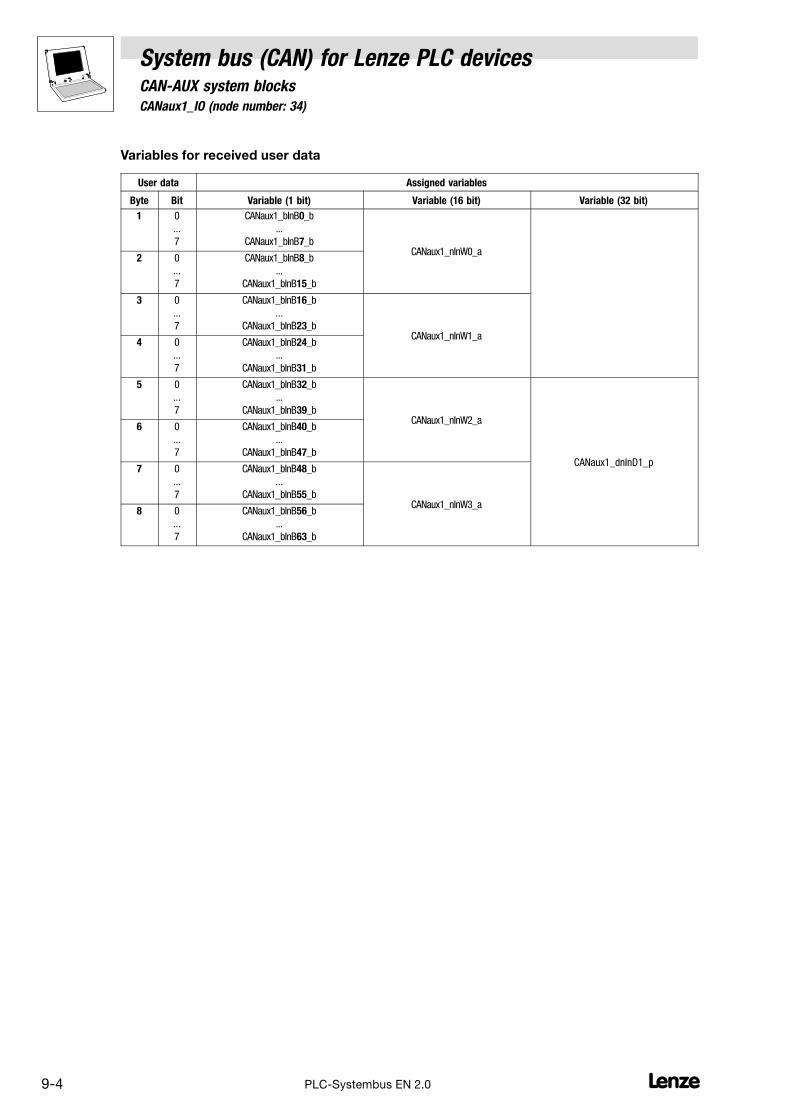
9.1 CANaux1_IO (node number: 34)
System bus (CAN) for Lenze PLC devicesCAN−AUX system blocks
9−4 LPLC−Systembus EN 2.0
Variables for received user data
User data Assigned variables
Byte Bit Variable (1 bit) Variable (16 bit) Variable (32 bit)
1 0
...
7
CANaux1_bInB0_b
...
CANaux1_bInB7_bCANaux1_nInW0_a
2 0
...
7
CANaux1_bInB8_b
...
CANaux1_bInB15_b
3 0
...
7
CANaux1_bInB16_b
...
CANaux1_bInB23_bCANaux1_nInW1_a
4 0
...
7
CANaux1_bInB24_b
...
CANaux1_bInB31_b
5 0
...
7
CANaux1_bInB32_b
...
CANaux1_bInB39_bCANaux1_nInW2_a
CANaux1_dnInD1_p
6 0
...
7
CANaux1_bInB40_b
...
CANaux1_bInB47_b
7 0
...
7
CANaux1_bInB48_b
...
CANaux1_bInB55_bCANaux1_nInW3_a
8 0
...
7
CANaux1_bInB56_b
...
CANaux1_bInB63_b

System bus (CAN) for Lenze PLC devicesCAN−AUX system blocks
9.2 CANaux2_IO (node number: 35)
9−1L PLC−Systembus EN 2.0
9.2 CANaux2_IO (node number: 35)
This SB serves to transmit event−controlled or time−controlled process data via the system bus.
� The setting of the transmission mode (event− or time−controlled) is effected via C2456. (� 3−6)
� A sync telegram is not required.
CANaux2_nInW1_a
CANaux2_nInW2_a
CANaux2_bInB _b0...15
CANaux2_bInB _b16...31
Byte
7
8
5
6
3
4
1
2
Byte
7
8
5
6
3
4
1
2
CANaux2_nOutW1_a
CANaux2_nOutW2_a
CANaux2_nOutW3_a
CANaux2_bFDO _b16...31
CANaux2_dnOutD1_p
CANaux2_IO
DINT
WORD
WORD
WORD
16 x BOOL
DINT
Output user data(8 bytes)
Input user data(8 bytes)
L
H
L
H
CANaux2_bFDO _b0...1516 x BOOL
CANaux2_nOutW4_a WORD
WORD
WORD
16 x BOOL
16 x BOOL
CANaux2_nInW3_a
CANaux2_nInW4_a
WORD
WORD
CANaux2_dnInD1_p
C2493/4
C2493/5
C2493/6
C2493/7
C2492/4
C2492/5
C2491/3
C2491/4
C2492/6
C2492/7
CAN-AUX System bus interface
Fig. 9−2 CANaux2_IOsystem block
Tip!
Via C2457/2 you can set the monitoring time for the data reception. (Lenze setting: 3000 ms)
� Further information on this subject can be found in chapter 3.12.1. (� 3−11)
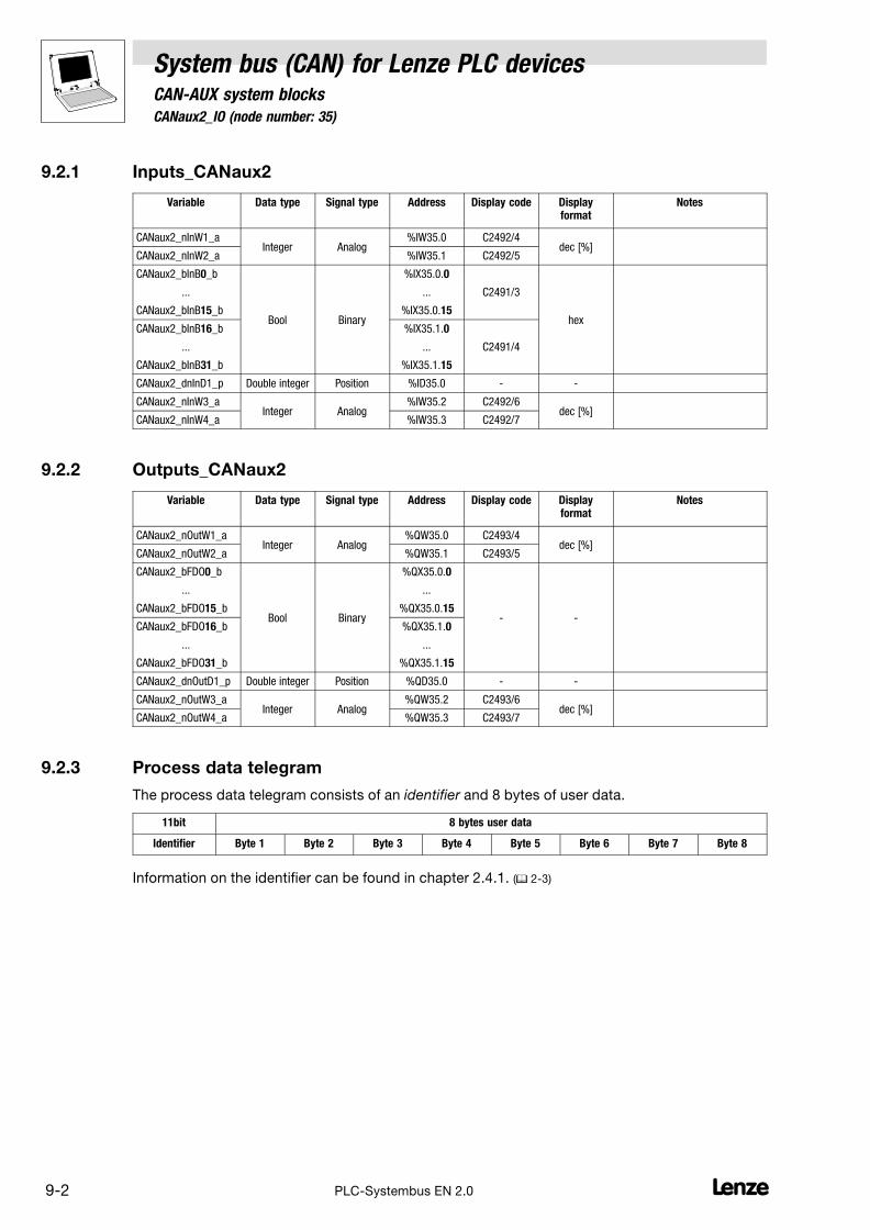
9.2 CANaux2_IO (node number: 35)
System bus (CAN) for Lenze PLC devicesCAN−AUX system blocks
9−2 LPLC−Systembus EN 2.0
9.2.1 Inputs_CANaux2
Variable Data type Signal type Address Display code Displayformat
Notes
CANaux2_nInW1_aInteger Analog
%IW35.0 C2492/4dec [%]
CANaux2_nInW2_a %IW35.1 C2492/5
CANaux2_bInB0_b
Bool Binary
%IX35.0.0
hex
... ... C2491/3
CANaux2_bInB15_b %IX35.0.15
CANaux2_bInB16_b %IX35.1.0
... ... C2491/4
CANaux2_bInB31_b %IX35.1.15
CANaux2_dnInD1_p Double integer Position %ID35.0 − −
CANaux2_nInW3_aInteger Analog
%IW35.2 C2492/6dec [%]
CANaux2_nInW4_a %IW35.3 C2492/7
9.2.2 Outputs_CANaux2
Variable Data type Signal type Address Display code Displayformat
Notes
CANaux2_nOutW1_aInteger Analog
%QW35.0 C2493/4dec [%]
CANaux2_nOutW2_a %QW35.1 C2493/5
CANaux2_bFDO0_b
Bool Binary
%QX35.0.0
− −
... ...
CANaux2_bFDO15_b %QX35.0.15
CANaux2_bFDO16_b %QX35.1.0
... ...
CANaux2_bFDO31_b %QX35.1.15
CANaux2_dnOutD1_p Double integer Position %QD35.0 − −
CANaux2_nOutW3_aInteger Analog
%QW35.2 C2493/6dec [%]
CANaux2_nOutW4_a %QW35.3 C2493/7
9.2.3 Process data telegram
The process data telegram consists of an identifier and 8 bytes of user data.
11bit 8 bytes user data
Identifier Byte 1 Byte 2 Byte 3 Byte 4 Byte 5 Byte 6 Byte 7 Byte 8
Information on the identifier can be found in chapter 2.4.1. (� 2−3)

System bus (CAN) for Lenze PLC devicesCAN−AUX system blocks
9.2 CANaux2_IO (node number: 35)
9−3L PLC−Systembus EN 2.0
9.2.4 Assignment of the user data to variables
Several variables of different data types are assigned to the user data to be transmitted and received.Thus, the data in the PLC program can be optionally interpreted as:
� binary information (1 bit)
� status word/quasi−analog value (16 bit)
� angle information (32 bit)
Variables for user data to be transmitted
User data Assigned variables
Byte Bit Variable (1 bit) Variable (16 bit) Variable (32 bit)
1 0
...
7
CANaux2_bFDO0_b
...
CANaux2_bFDO7_bCANaux2_nOutW1_a
CANaux2_dnOutD1_p
2 0
...
7
CANaux2_bFDO8_b
...
CANaux2_bFDO15_b
3 0
...
7
CANaux2_bFDO16_b
...
CANaux2_bFDO23_bCANaux2_nOutW2_a
4 0
...
7
CANaux2_bFDO24_b
...
CANaux2_bFDO31_b
5 0...7CANaux2_nOutW3_a
6 0...7
7 0...7CANaux2_nOutW4_a
8 0...7
Note!
Avoid simultaneous overwriting via different variable types to ensure data consistency.
For instance, if you want to write bytes 1 and 2, only use the variable CANaux2_dnOutD1_p,CANaux2_nOutW1_a, or only the variables CANaux2_bFDO0_b ... CANaux2_bFDO15_b for thispurpose!
Variables for received user data
User data Assigned variables
Byte Bit Variable (1 bit) Variable (16 bit) Variable (32 bit)
1 0
...
7
CANaux2_bInB0_b
...
CANaux2_bInB7_bCANaux2_nInW1_a
CANaux2_dnInD1_p
2 0
...
7
CANaux2_bInB8_b
...
CANaux2_bInB15_b
3 0
...
7
CANaux2_bInB16_b
...
CANaux2_bInB23_bCANaux2_nInW2_a
4 0
...
7
CANaux2_bInB24_b
...
CANaux2_bInB31_b
5 0...7CANaux2_nInW3_a
6 0...7
7 0...7CANaux2_nInW4_a
8 0...7

System bus (CAN) for Lenze PLC devicesCAN−AUX system blocks
9.3 CANaux3_IO (node number: 36)
9−1L PLC−Systembus EN 2.0
9.3 CANaux3_IO (node number: 36)
This SB serves to transmit event−controlled or time−controlled process data via the system bus.
� The setting of the transmission mode (event− or time−controlled) is effected via C2456. (� 3−6)
� A sync telegram is not required.
CANaux3_nInW1_a
CANaux3_nInW2_a
CANaux3_bInB _b0...15
CANaux3_bInB _b16...31
Byte
7
8
5
6
3
4
1
2
Byte
7
8
5
6
3
4
1
2
CANaux3_nOutW1_a
CANaux3_nOutW2_a
CANaux3_nOutW3_a
CANaux3_bFDO _b16...31
CANaux3_dnOutD1_p
CANaux3_IO
DINT
WORD
WORD
WORD
16 x BOOL
DINT
Output user data(8 bytes)
Input user data(8 bytes)
L
H
L
H
CANaux3_bFDO _b0...1516 x BOOL
CANaux3_nOutW4_a WORD
WORD
WORD
16 x BOOL
16 x BOOL
CANaux3_nInW3_a
CANaux3_nInW4_a
WORD
WORD
CANaux3_dnInD1_p
C2493/8
C2493/9
C2493/10
C2493/11
C2492/8
C2492/9
C2492/5
C2491/6
C2492/10
C2492/11
CAN-AUX System bus interface
Fig. 9−3 CANaux3_IOsystem block
Tip!
Via C2457/3 you can set the monitoring time for the data reception. (Lenze setting: 3000 ms)
� Further information on this subject can be found in chapter 3.12.1. (� 3−11)

9.3 CANaux3_IO (node number: 36)
System bus (CAN) for Lenze PLC devicesCAN−AUX system blocks
9−2 LPLC−Systembus EN 2.0
9.3.1 Inputs_CANaux3
Variable Data type Signal type Address Display code Displayformat
Notes
CANaux3_nInW1_aInteger Analog
%IW36.0 C2492/8dec [%]
CANaux3_nInW2_a %IW36.1 C2492/9
CANaux3_bInB0_b
Bool Binary
%IX36.0.0
hex
... ... C2491/5
CANaux3_bInB15_b %IX36.0.15
CANaux3_bInB16_b %IX36.1.0
... ... C2491/6
CANaux3_bInB31_b %IX36.1.15
CANaux3_dnInD1_p Double integer Position %ID36.0 − −
CANaux3_nInW3_aInteger Analog
%IW36.2 C2492/10dec [%]
CANaux3_nInW4_a %IW36.3 C2492/11
9.3.2 Outputs_CANaux3
Variable Data type Signal type Address Display code Displayformat
Notes
CANaux3_nOutW1_aInteger Analog
%QW36.0 C2493/8dec [%]
CANaux3_nOutW2_a %QW36.1 C2493/9
CANaux3_bFDO0_b
Bool Binary
%QX36.0.0
− −
... ...
CANaux3_bFDO15_b %QX36.0.15
CANaux3_bFDO16_b %QX36.1.0
... ...
CANaux3_bFDO31_b %QX36.1.15
CANaux3_dnOutD1_p Double integer Position %QD36.0 − −
CANaux3_nOutW3_aInteger Analog
%QW36.2 C2493/10dec [%]
CANaux3_nOutW4_a %QW36.3 C2493/11
9.3.3 Process data telegram
The process data telegram consists of an identifier and 8 bytes of user data.
11bit 8 bytes user data
Identifier Byte 1 Byte 2 Byte 3 Byte 4 Byte 5 Byte 6 Byte 7 Byte 8
Information on the identifier can be found in chapter 2.4.1. (� 2−3)
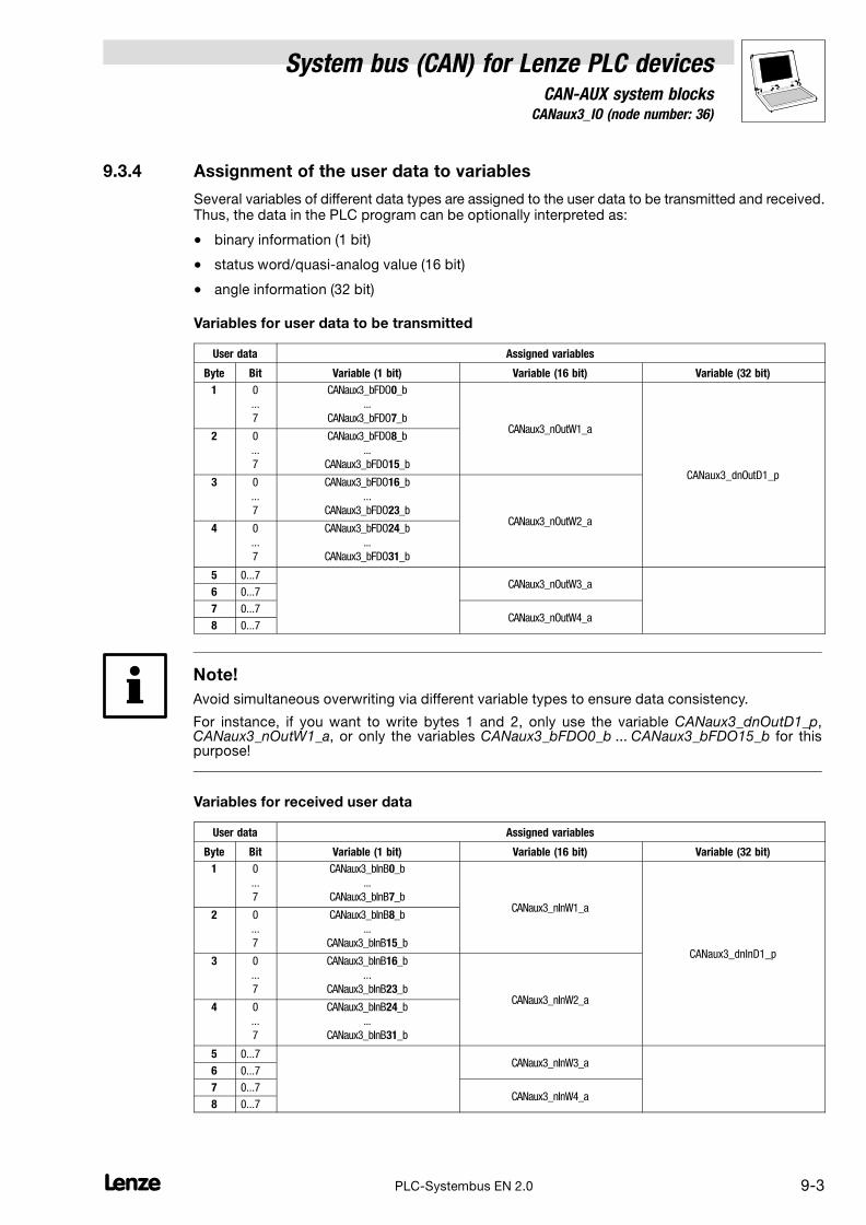
System bus (CAN) for Lenze PLC devicesCAN−AUX system blocks
9.3 CANaux3_IO (node number: 36)
9−3L PLC−Systembus EN 2.0
9.3.4 Assignment of the user data to variables
Several variables of different data types are assigned to the user data to be transmitted and received.Thus, the data in the PLC program can be optionally interpreted as:
� binary information (1 bit)
� status word/quasi−analog value (16 bit)
� angle information (32 bit)
Variables for user data to be transmitted
User data Assigned variables
Byte Bit Variable (1 bit) Variable (16 bit) Variable (32 bit)
1 0
...
7
CANaux3_bFDO0_b
...
CANaux3_bFDO7_bCANaux3_nOutW1_a
CANaux3_dnOutD1_p
2 0
...
7
CANaux3_bFDO8_b
...
CANaux3_bFDO15_b
3 0
...
7
CANaux3_bFDO16_b
...
CANaux3_bFDO23_bCANaux3_nOutW2_a
4 0
...
7
CANaux3_bFDO24_b
...
CANaux3_bFDO31_b
5 0...7CANaux3_nOutW3_a
6 0...7
7 0...7CANaux3_nOutW4_a
8 0...7
Note!
Avoid simultaneous overwriting via different variable types to ensure data consistency.
For instance, if you want to write bytes 1 and 2, only use the variable CANaux3_dnOutD1_p,CANaux3_nOutW1_a, or only the variables CANaux3_bFDO0_b ... CANaux3_bFDO15_b for thispurpose!
Variables for received user data
User data Assigned variables
Byte Bit Variable (1 bit) Variable (16 bit) Variable (32 bit)
1 0
...
7
CANaux3_bInB0_b
...
CANaux3_bInB7_bCANaux3_nInW1_a
CANaux3_dnInD1_p
2 0
...
7
CANaux3_bInB8_b
...
CANaux3_bInB15_b
3 0
...
7
CANaux3_bInB16_b
...
CANaux3_bInB23_bCANaux3_nInW2_a
4 0
...
7
CANaux3_bInB24_b
...
CANaux3_bInB31_b
5 0...7CANaux3_nInW3_a
6 0...7
7 0...7CANaux3_nInW4_a
8 0...7

9.4 CANaux_Management (node number: 111)
System bus (CAN) for Lenze PLC devicesCAN−AUX system blocks
9−4 LPLC−Systembus EN 2.0
9.4 CANaux_Management (node number: 111)
By means of this SB
� a reset node can be activated, e. g. to accept changes with regard to the baud rate andaddressings.
� Communication error, Bus−off state, and further states can be processed in the PLCprogram.
� the instant of transmission of CANaux2_OUT and CANaux3_OUT can be influenced.
CANaux_bResetNode_b
CANaux_Management
C2458
CANaux2_OUT
CANaux_bCe2CommErrCanIn2_b
CANaux_ResetNode
CANaux_bTxCan2Synchronized_b
CANaux1_INCommunication error
CANaux2_INCommunication error
CANaux3_INCommunication error
CAN-AUXBus off state
CANaux_bCe1CommErrCanIn1_b
CANaux_bCe3CommErrCanIn3_b
CANaux_bCe4BusOffState_b
CAN_SYNC
CANaux3_OUTCANaux_bTxCan3Synchronized_b
CAN_SYNC
1
CAN-AUXNode address (C2450)
CAN-AUXState (C2459)
CANaux_byNodeAddress
CANaux_byState
Fig. 9−4 CANaux_Managementsystem block
Note!
The process image for this SB is generated in a fixed system task (interval: 1 ms).
9.4.1 Inputs_CANaux_Management
Identifier Data type Signal type Address DIS DIS format Information
CANaux_bCe1CommErrCanIn1_b
Bool Binary
%IX111.0.0
− −
CANaux1_IN communication error
CANaux_bCe2CommErrCanIn1_b %IX111.0.1 CANaux2_IN communication error
CANaux_bCe3CommErrCanIn1_b %IX111.0.2 CANaux3_IN communication error
CANaux_bCe4BusOffState_b %IX111.0.3 CAN−AUX bus "off state" recognised
CANaux_byNodeAddressByte −
%IB111.2 C2450 − CAN−AUX node address
CANaux_byState %IB111.3 C2459 − CAN−AUX status

System bus (CAN) for Lenze PLC devicesCAN−AUX system blocks
9.4 CANaux_Management (node number: 111)
9−5L PLC−Systembus EN 2.0
9.4.2 Outputs_CANaux_Management
Identifier Data type Signal type Address DIS DIS format Information
CANaux_bResetNode_b
Bool Binary
%QX111.0.0
− −
Carry out reset node of the CANaux
CANaux_bTxCan2Synchronized_b %QX111.0.1 Transfer CANaux2_OUT with synctelegram.
CANaux_bTxCan3Synchronized_b %QX111.0.2 Transfer CANaux3_OUT with synctelegram.
Note!
If CANaux_bTxCan2Synchronized_b and/or CANaux_bTxCan3Synchronized_b are integrated, it isrequired to configure the device as sync transmitter. The data are transmitted immediately after thesync telegram is sent.
9.4.3 Activating a reset node
A reset node can be activated by setting CANaux_bResetNode_b to TRUE or C2458 = .
Tip!
Even if the CANaux_Management SB has not been assigned to the control configuration, a resetnode can be activated via C2458. (� 3−8)
9.4.4 Defining the instant of transmission for CANaux2_OUT/CANaux3_OUT
Via CANaux_bTxCan2Synchonized_b and CANaux_bTxCan3Synchonized_b you define the instantof transmission for the CAN objects CANaux2_OUT and CANaux3_OUT:
� FALSE: Data from the CANaux2_OUT/CANaux3_OUT are transmitted at the end of theprocess image.
� TRUE: Data from the CANaux2_OUT/CANaux3_OUT are sent to sync.
– The identifiers for the sync transmission and reception telegram can be set viaC2467/C2468.
– The sync Tx time can be set via C2469.

9.4 CANaux_Management (node number: 111)
System bus (CAN) for Lenze PLC devicesCAN−AUX system blocks
9−6 LPLC−Systembus EN 2.0
9.4.5 Status messages
The CANaux_Management SB provides different status messages which can be processed in thePLC program:
Identifier Information
CANaux_bCe1CommErrCanIn1_b TRUE CANaux1_IN communication error
CANaux_bCe2CommErrCanIn1_b TRUE CANaux2_IN communication error
CANaux_bCe3CommErrCanIn1_b TRUE CANaux3_IN communication error
CANaux_bCe4BusOffState_b TRUE CAN−AUX−bus "off state" recognised
CANaux_byNodeAddress 1...63 CAN−AUX node address (� 3−3)
CANaux_byState Operating status of the system bus
1 Operational
2 Pre−operational
3 Warning
4 Bus−off
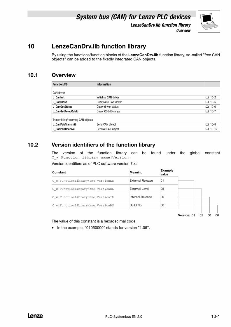
System bus (CAN) for Lenze PLC devicesLenzeCanDrv.lib function library
10.1 Overview
10−1L PLC−Systembus EN 2.0
10 LenzeCanDrv.lib function library
By using the functions/function blocks of the LenzeCanDrv.lib function library, so−called "free CANobjects" can be added to the fixedly integrated CAN objects.
10.1 Overview
Function/FB Information
CAN driver
L_CanInit Initialise CAN driver � 10−2
L_CanClose Deactivate CAN driver � 10−5
L_CanGetStatus Query driver status � 10−6
L_CanGetRelocCobId Query COB−ID range � 10−7
Transmitting/receiving CAN objects
L_CanPdoTransmit Send CAN object � 10−8
L_CanPdoReceive Receive CAN object � 10−12
10.2 Version identifiers of the function library
The version of the function library can be found under the global constantC_w[Function library name]Version .
Version identifiers as of PLC software version 7.x:
Constant MeaningExample
value
C_w[FunctionLibraryName]VersionER External Release 01
C_w[FunctionLibraryName]VersionEL External Level 05
C_w[FunctionLibraryName]VersionIR Internal Release 00
C_w[FunctionLibraryName]VersionBN Build No. 00
Version: 01 05 00 00
The value of this constant is a hexadecimal code.
� In the example, "01050000" stands for version "1.05".

10.3 L_CanInit − initialising the CAN driver
System bus (CAN) for Lenze PLC devicesLenzeCanDrv.lib function library
10−2 LPLC−Systembus EN 2.0
10.3 L_CanInit − initialising the CAN driver
Function
DWORD L_CanInit (wDrvNr, dwRelocCobIdArea)
Before it is possible to work with the free CAN objects, an initialisation of the CAN driver has to becarried out.
� By repeatedly calling this function, the CAN driver in the initialised state can be switched overto other parameters.
– The acceptance of the new parameters is effected immediately and therefore can have animpact on transmission and reception jobs which are still pending. Thus, the function maynot be called cyclically.
L_CanInit
wDrvNrdwRelocCobId
Transfer parameters
Identifier Data type Possible settings Information
wDrvNr Word 10 System bus
dwRelocCobIdArea Double Word
0
192...319
832...1344
1664...1728
1856...1984
Identifier area − Only relevant for 9300 Servo PLC!
dwRelocCobIdArea = 832 (Lenze setting)
Free range 1
Free range 2
Free range 3
Free range 4
Return value
Data type Bit Value Meaning Priority
Double Word 0 0 Driver is initialised. −
1 Error during initialisation.
� In this case the bits 1 ... 31 are all set to "1" and therefore are invalid.
1 0 Setting dwRelocCobIdAreaOK.
1 Setting dwRelocCobIdAreanot OK.
� The identifier area featuring 64 objects overlaps with another area or is settledbeyond the limits 0 ... 2047.
2 0 Free object found.
1 No free object found.
Remedy:
� Do not use one of the CAN objects CAN1_IN ... CAN3_IN or CAN1_OUT ... CAN3_OUT.
� Set C2118 to �0" (write parameters via SDO2).PLEASE NOTE: at C2118 = 0 the SDO2 channel is no longer available!
� Switch off generation of the sync object (C0369 = 0).
3−15 Reserved for future supplements (bits are set to "0").
16−31 Version of the LenzeCanDrv.lib
function library
Format: main version/subversion (e. g. 0103hex = version 1.03)

System bus (CAN) for Lenze PLC devicesLenzeCanDrv.lib function library
10.3 L_CanInit − initialising the CAN driver
10−3L PLC−Systembus EN 2.0
Reception identifier area
Fig. 10−1 shows the identifier area provided for data reception.
� Basically the entire identifier area of 0 ... 2047 is provided.
� The grayed out fields in Fig. 10−1 are pre−assigned for specific applications, e. g. for networkmanagement commands and process data.
� Fields which are not pre−assigned are designated as free area 1 ... 4.
Note on the 9300 Servo PLC (firmware version 2.6 or lower)!
In contrast to the Drive PLC, in the case of the 9300 Servo PLC due to memory limitations only thefollowing data can be received at the same time:
� Data with identifiers within the grayed out fields in Fig. 10−1.
� Data with identifiers within the identifier field COB−ID field featuring 64 objects.
NMT commands
0
127
Tx−sync 128
Alarm objects
129
191
Free range 1
192
383
Process data objects (PDO)
384
831
COB−ID field
(shiftable identifier field − Lenze setting)
832
895
COB−ID area
(only relevant for 9300 Servo PLC)
For the simultaneous data reception concerning the 9300Servo PLC in addition to the pre−assigned areas, 64further identifiers are provided to you via the COB−ID area.
� In the Lenze setting these are the identifiers832 ... 895.
� If you require other identifiers you can shift the COB−IDarea within the free areas 1...4 during initialisationusing the variable dwRelocCobIdArea.
� If the COB−ID area by means of dwRelocCobIdArea isshifted in a way that causes an overlapping with afixedly predefined area, an error in the return value ofthe function is reported.(Bit 0 = 1 / Bit 1 = 1)
Free range 2
1407
Service data objects (SDO)
1408
1663
Free range 3
1664
1791
Node monitoring
1792
1855
Free range 4
1856
2047
Fig. 10−1 Pre−assigned and free identifier fields as well as relocatable COB−ID area for 9300 Servo PLC
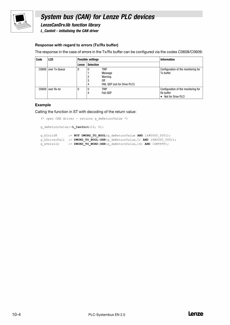
10.3 L_CanInit − initialising the CAN driver
System bus (CAN) for Lenze PLC devicesLenzeCanDrv.lib function library
10−4 LPLC−Systembus EN 2.0
Response with regard to errors (Tx/Rx buffer)
The response in the case of errors in the Tx/Rx buffer can be configured via the codes C0608/C0609:
Code LCD Possible settings Information
Lenze Selection
C0608 over Tx−Queue 0 0 TRIP
1 Message
2 Warning
3 Off
4 FAIL QSP (not for Drive PLC!)
Configuration of the monitoring for
Tx buffer
C0609 over Rx−lsr 0 0 TRIP
4 Fail−QSP
Configuration of the monitoring for
Rx buffer
� Not for Drive PLC!
Example
Calling the function in ST with decoding of the return value:
(* open CAN driver − returns g_dwReturnValue *)
g_dwReturnValue:=L_CanInit(10, 0);
g_bInitOK := NOT DWORD_TO_BOOL(g_dwReturnValue AND 16#0000_0001);
g_bDriverFail := DWORD_TO_BOOL(SHR(g_dwReturnValue,1) AND 16#0000_0001);
g_wVersion := DWORD_TO_WORD(SHR(g_dwReturnValue,16) AND 16#FFFF);
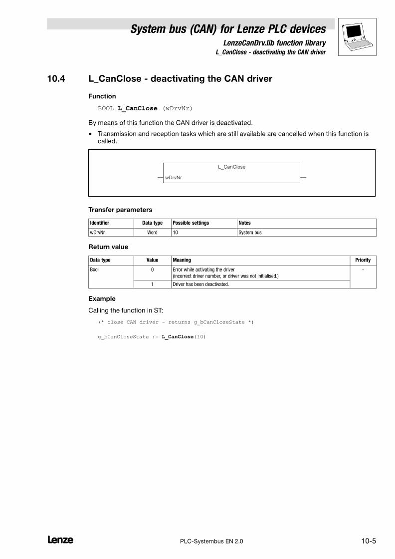
System bus (CAN) for Lenze PLC devicesLenzeCanDrv.lib function library
10.4 L_CanClose − deactivating the CAN driver
10−5L PLC−Systembus EN 2.0
10.4 L_CanClose − deactivating the CAN driver
Function
BOOL L_CanClose (wDrvNr)
By means of this function the CAN driver is deactivated.
� Transmission and reception tasks which are still available are cancelled when this function iscalled.
L_CanClose
wDrvNr
Transfer parameters
Identifier Data type Possible settings Notes
wDrvNr Word 10 System bus
Return value
Data type Value Meaning Priority
Bool 0 Error while activating the driver
(incorrect driver number, or driver was not initialised.)
−
1 Driver has been deactivated.
Example
Calling the function in ST:
(* close CAN driver − returns g_bCanCloseState *)
g_bCanCloseState := L_CanClose(10)

10.5 L_CanGetStatus − querying the driver status
System bus (CAN) for Lenze PLC devicesLenzeCanDrv.lib function library
10−6 LPLC−Systembus EN 2.0
10.5 L_CanGetStatus − querying the driver status
Function
DWORD L_CanGetStatus (wDrvNr)
By means of this function the status of the CAN driver can be determined.
L_CanGetStatus
wDrvNr
Transfer parameters
Identifier Data type Possible settings Information
wDrvNr Word 10 System bus
Return value
Data type Bit Value Meaning Priority
Double Word 0, 1 0 CAN driver is Operational. −
1 CAN driver is not available or not initialised.
� In this case the bits 16 ... 31 are all set to "1" and therefore are invalid.
2 CAN driver is Pre−operational.
3 CAN driver is stopped.
Double Word 2...15 Reserved for future supplements (bits are set to "0").
16...31 Version of the CAN driver
Format: main version/subversion (e. g. 0103hex = version 1.03)
Example
Calling the function in ST:
g_dwCanDrvState:=L_Can_GetStatus(10);
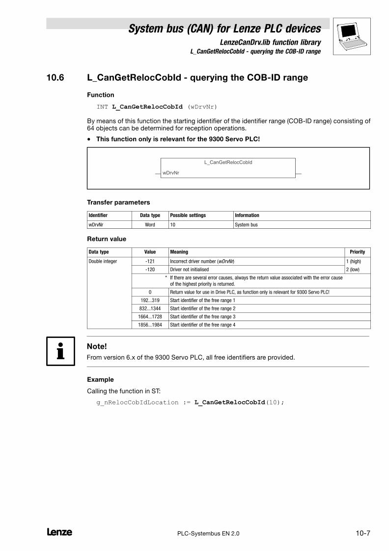
System bus (CAN) for Lenze PLC devicesLenzeCanDrv.lib function library
10.6 L_CanGetRelocCobId − querying the COB−ID range
10−7L PLC−Systembus EN 2.0
10.6 L_CanGetRelocCobId − querying the COB−ID range
Function
INT L_CanGetRelocCobId (wDrvNr)
By means of this function the starting identifier of the identifier range (COB−ID range) consisting of64 objects can be determined for reception operations.
� This function only is relevant for the 9300 Servo PLC!
L_CanGetRelocCobId
wDrvNr
Transfer parameters
Identifier Data type Possible settings Information
wDrvNr Word 10 System bus
Return value
Data type Value Meaning Priority
Double integer −121 Incorrect driver number (wDrvNr) 1 (high)
−120 Driver not initialised 2 (low)
* If there are several error causes, always the return value associated with the error cause
of the highest priority is returned.
0 Return value for use in Drive PLC, as function only is relevant for 9300 Servo PLC!
192...319 Start identifier of the free range 1
832...1344 Start identifier of the free range 2
1664...1728 Start identifier of the free range 3
1856...1984 Start identifier of the free range 4
Note!
From version 6.x of the 9300 Servo PLC, all free identifiers are provided.
Example
Calling the function in ST:
g_nRelocCobIdLocation := L_CanGetRelocCobId(10);

10.7 L_CanPdoTransmit − transmitting a CAN object
System bus (CAN) for Lenze PLC devicesLenzeCanDrv.lib function library
10−8 LPLC−Systembus EN 2.0
10.7 L_CanPdoTransmit − transmitting a CAN object
Function block
This FB serves to transmit data via the system bus interface according to CANopen.
� The data transmission is carried out simultaneously to the process of the PLC program by theoperating system of the controller, whereby an object can be max. sent every 250 �s.
L_CanPdoTransmit
wDrvNrbyLendwCobIdpIOAdresstRepeatTimebyTransmitMode
nStatewNrOfCallsToSend
Identifier Data type Variable type Possible settings Information
wDrvNr Word VAR_INPUT 10 System bus
byLen Byte VAR_INPUT 0...8 Telegram length (in bytes)
dwCobID Double Word VAR_INPUT 0...2047 CAN identifier
pIOAdress Pointer to Byte VAR_INPUT Pointer to the address in thememory from which the databytes to be transmitted arestored.
The address of a variable can be determined viathe address function ADR.
tRepeatTime Time VAR_INPUT
T#0s
T#xms
Parameter for the time−controlled transmission
(byTransmitMode = 1/2)
� Transmission takes place at each call of theFB.
� TRansmission takes place after the set cycletime x (in ms) has expired.
byTransmitMode Byte VAR_INPUT 0 Event−controlled transmission
� Transmission takes place if the input datahave changed.
� If the bus state changes from Pre−operational to Operational, the telegramon principle is transmitted once.
1 Time−controlled transmission
� Transmission takes place after the cycle timeset via tRepeatTime has expired.
2 Time−controlled transmission with superimposedevent control
� Transmission takes place after the cycle timeset via tRepeatTime has expired, and if thetransmitted data have changed.
3 Forced transmission
� Transmission takes place if the action <Instance name>.SendData iscalled, irrespective of the cycle time set.
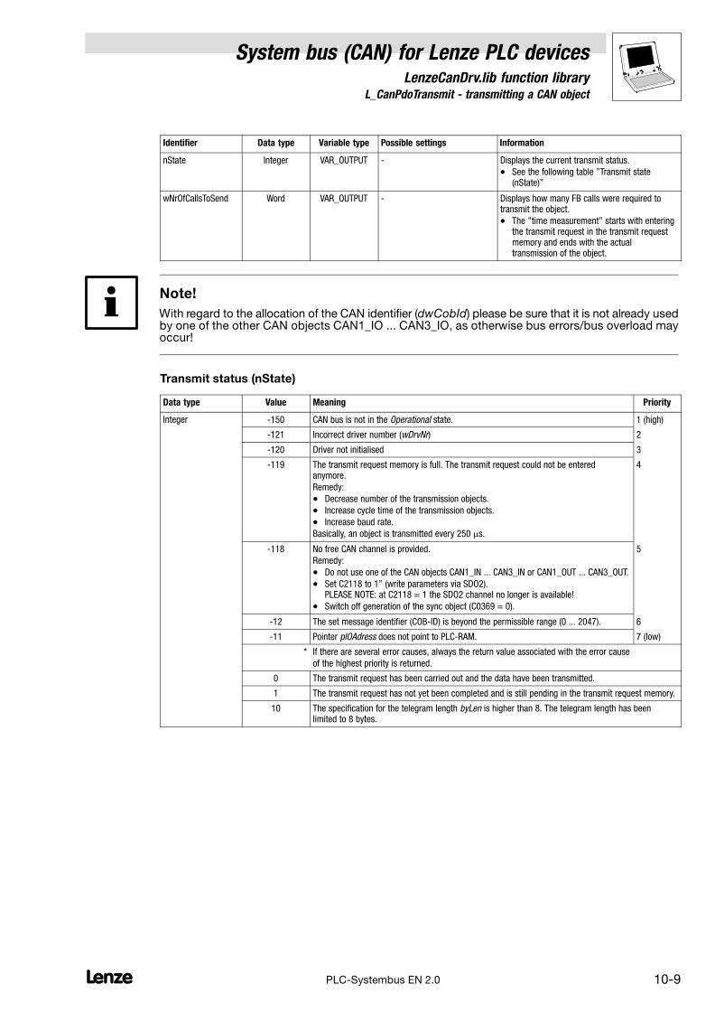
System bus (CAN) for Lenze PLC devicesLenzeCanDrv.lib function library
10.7 L_CanPdoTransmit − transmitting a CAN object
10−9L PLC−Systembus EN 2.0
Identifier InformationPossible settingsVariable typeData type
nState Integer VAR_OUTPUT − Displays the current transmit status.
� See the following table "Transmit state(nState)"
wNrOfCallsToSend Word VAR_OUTPUT − Displays how many FB calls were required totransmit the object.
� The "time measurement" starts with enteringthe transmit request in the transmit requestmemory and ends with the actualtransmission of the object.
Note!
With regard to the allocation of the CAN identifier (dwCobId) please be sure that it is not already usedby one of the other CAN objects CAN1_IO ... CAN3_IO, as otherwise bus errors/bus overload mayoccur!
Transmit status (nState)
Data type Value Meaning Priority
Integer −150 CAN bus is not in the Operational state. 1 (high)
−121 Incorrect driver number (wDrvNr) 2
−120 Driver not initialised 3
−119 The transmit request memory is full. The transmit request could not be enteredanymore.
Remedy:
� Decrease number of the transmission objects.
� Increase cycle time of the transmission objects.
� Increase baud rate.
Basically, an object is transmitted every 250 �s.
4
−118 No free CAN channel is provided.
Remedy:
� Do not use one of the CAN objects CAN1_IN ... CAN3_IN or CAN1_OUT ... CAN3_OUT.
� Set C2118 to 1" (write parameters via SDO2).PLEASE NOTE: at C2118 = 1 the SDO2 channel no longer is available!
� Switch off generation of the sync object (C0369 = 0).
5
−12 The set message identifier (COB−ID) is beyond the permissible range (0 ... 2047). 6
−11 Pointer pIOAdress does not point to PLC−RAM. 7 (low)
* If there are several error causes, always the return value associated with the error cause
of the highest priority is returned.
0 The transmit request has been carried out and the data have been transmitted.
1 The transmit request has not yet been completed and is still pending in the transmit request memory.
10 The specification for the telegram length byLen is higher than 8. The telegram length has beenlimited to 8 bytes.

10.7 L_CanPdoTransmit − transmitting a CAN object
System bus (CAN) for Lenze PLC devicesLenzeCanDrv.lib function library
10−10 LPLC−Systembus EN 2.0
Transmit request memory as an interface between the CAN driver and the
L_CanPdoTransmitFB
As the data transmission via the CAN driver is effected simultaneously to the process of the PLCprogram, a temporary storage for the transmit requests, the so−called transmit request memory, isused between the CAN driver and the L_CanPdoTransmit FB.
L_CanPdoTransmit
L_CanPdoTransmit
Transmit request 1
CAN driver
System bus (CAN)
250 s cycle�
PLC program Operating system
Transmission request memory
L_ParWrite
Transmit request 2
Transmit request 3
Transmit request 64
� Every time the L_CanPdoTransmit FB is called, a transmit request is stored in the transmitrequest memory.
� Transmit requests can also be stored in the transmit request memory using the L_ParWrite FBof the LenzeDrive.lib function library.
� The transmit request memory can buffer 64 transmit requests of the L_CanPdoTransmit orL_ParWrite FBs at a total.
� Every 250 �s, simultaneously to the process of the PLC program, a transmit request iscollected from the transmit request memory and is processed by the operating system.
Note!
If the transmit request memory due to a too frequent call of the L_CanPdoTransmit or L_ParWriteFBs is filled up faster as it is emptied by the operating system which collects the transmit requests,an overflow error will occur.
� In the case of an overflow error, the variable nState receives the value "−119".
� Additionally a corresponding error message is output by the operating system.(See chapter "Error messages" in the Manual to the respective target system, e. g.9300 Servo PLC, Drive PLC, or ECSxA).

System bus (CAN) for Lenze PLC devicesLenzeCanDrv.lib function library
10.7 L_CanPdoTransmit − transmitting a CAN object
10−11L PLC−Systembus EN 2.0
Forced transmission
Some cases may require an entry of a transmit request in the transmit request memory withoutconsidering a data change (event−controlled) or a cycle time (time−controlled).
For this purpose, the L_CanPdoTransmit FB supports the action SendData in the "Forcedtransmission" transmit mode (byTransmitMode = 3).
Example
Declaration of the function block in ST:
SendWithID678: L_CanPdoTransmit; (* send data with identifier 678 *)
Calling the function block in ST:
SendWithID678 (wDrvNr:=10, byLen:=8, dwCobID:=678, pIOAdress:=ADR(abySendData), tRepeatTime:=T#5ms, byTransmitMode:=3);
Action "Forced transmission" in ST:
SendWithID678.SendData; (* force send procedure *)
Note!
The use of an address which is stored in the memory area of the operating system is not permittedfor the L_CanPdoTransmit and L_CanPdoReceiveFBs!
Problem:
The addresses of the system variables (inputs/outputs of systemblocks) are also placed in the memory area of the operating system, inthe following illustration the system variable AIN1_nIn_a:
Remedy:
Instead of the address of the system variable, use the address of atemporary variable, which the value of the corresponding systemvariable is copied into:
ADR
2
AIN1_nIn_a
L_CanPdoTransmit
wDrvNrbyLendwCobIdpIOAdresstRepeatTimebyTransmitMode
nStatewNrOfCallsToSend
108
750
t#10ms nAnalogInput
AIN1_nIn_a nAnalogInput
ADR
2
L_CanPdoTransmit
wDrvNrbyLendwCobIdpIOAdresstRepeatTimebyTransmitMode
nStatewNrOfCallsToSend
108
750
t#10ms

10.8 L_CanPdoReceive − receiving a CAN object
System bus (CAN) for Lenze PLC devicesLenzeCanDrv.lib function library
10−12 LPLC−Systembus EN 2.0
10.8 L_CanPdoReceive − receiving a CAN object
Function block
This FB serves to receive data via the system bus interface according to CANopen.
Tip!
An overload with regard to the receive process can occur if due to a high bus utilisation or very fasttransmission activities of the other nodes further receive telegrams already arrive while a receivetelegram is processed.
The operating system responds to this with an overflow error:
� A corresponding error message is output (see chapter "Error messages" in the Manual for therespective PLC, e. g. 9300 Servo PLC, Drive PLC, or ECSxA).
� Furthermore the CAN driver is deactivated for the free CAN objects and has to be reinitialisedvia the function L_CanInit.
L_CanPdoReceive
wDrvNrbyLendwCobIdpIOAdress
nStatebNewMessage
Identifier Data type Variable type Possible settings Information
wDrvNr Word VAR_INPUT 10 System bus
byLen Byte VAR_INPUT 0...8 Telegram length (in bytes)
dwCobID Double Word VAR_INPUT 0...2047 CAN identifier
pIOAdress Pointer to Byte VAR_INPUT Pointer to the address in thememory from which the databytes received are stored.
The address of a variable can be determined viathe address function ADR.
bNewMessage Bool VAR_OUTPUT − Is set to TRUE if data have been received, andonly is reset to FALSE by calling the followingaction:<Instancename>.ResetNewMessage
� If no reset is carried out, data can furthermorebe received, but data reception is notdisplayed.
nState Integer VAR_OUTPUT − Displays the current receive status.
� See the following table"Receive state (nState)"
Note!
With regard to the allocation of the CAN identifier (dwCobId) please be sure that it is not already usedby one of the other CAN objects CAN1_IO ... CAN3_IO, as otherwise incorrect data are received!

System bus (CAN) for Lenze PLC devicesLenzeCanDrv.lib function library
10.8 L_CanPdoReceive − receiving a CAN object
10−13L PLC−Systembus EN 2.0
Receive status (nState)
Data type Value Meaning Priority
Integer −150 CAN bus is not in the Operational state. 1 (high)
−121 Incorrect driver number (wDrvNr) 2
−120 Driver not initialised 3
−12 The set message identifier (COB−ID) is beyond the permissible range (0 ... 2047). 4
−11 Pointer pIOAdress does not point to PLC−RAM. 5 (low)
* If there are several error causes, always the value associated with the error cause
of the highest priority is returned.
0 Data have been faultlessly received.
10 The specification for the telegram length byLen is higher than 8. The telegram length has beenlimited to 8 bytes.
200 Data were received without resetting bNewMessage. Therefore valid data were possibly overwrittenin the receive memory.
Resetting the variable "bNewMessage"
If data have been received from the CAN bus, the output variable bNewMessage is set to TRUE andonly is reset to FALSE again by calling the action <Instance name>.ResetNewMessage:
(* FB instance *)
ReceiveFromID678: L_CanPdoReceive; (* receive data *) (* from identifier 678 *)...
(* reset NewMessage information at FB ReceiveFromID678 *)
ReceiveFromID678.ResetNewMessage; (* reset NewMessage *)
Example
Calling the function block in ST:
ReceiveFromID678(wDrvNr:=10, byLen:=8, dwCobID:=678, pIOAdress:=ADR(abyReceiveData);
Note!
The use of an address which is stored in the memory area of the operating system is not permittedfor the L_CanPdoTransmit and L_CanPdoReceiveFBs!
� See also note to the function L_CanPdoTransmit. (� 10−8)
10.8 L_CanPdoReceive − receiving a CAN object
System bus (CAN) for Lenze PLC devicesLenzeCanDrv.lib function library
10−14 LPLC−Systembus EN 2.0

System bus (CAN) for Lenze PLC devicesLenzeCanDSxDrv.lib function library
11.1 Overview
11−1L PLC−Systembus EN 2.0
11 LenzeCanDSxDrv.libfunction library
The LenzeCanDSxDrv.lib function library contains functions by means of which CAN indexesreceived via the system bus interface within the PLC can be "mapped" to other codes than to thosewhich are automatically allocated.
Furthermore functions/FBs are provided, by means of which the "Heartbeat" and "Node guarding"monitoring mechanisms for ensuring the function of system bus nodes can be realised.
Tip!
General information
� on the mapping of indexes to codes can be found in chapter 3.10. (� 3−8)
� on the "Heartbeat" and "Node Guarding" monitoring mechanisms can be found in chapter2.10. (� 2−21)
11.1 Overview
Function/FB Information
Mapping indexes to codes
� The functions are limited to the parameter access via the system bus interface integrated in the PLC.
L_CanDSxInitIndexCode Configure index mapping � 11−3
L_CanDSxOpen Activate index mapping � 11−5
L_CanDSxClose Deactivate index mapping again � 11−6
"Hearbeat" monitoring mechanism
L_CanDSxOpenHeartBeat Initialise "Heartbeat" � 11−7
L_CanDSxHeartBeat Carry out "Heartbeat" � 11−8
L_CanDSxCloseHeartBeat Deactivate "Heartbeat" again � 11−10
"Node guarding" monitoring mechanism
L_CanDSxOpenNodeGuarding Initialise "Node guarding" � 11−11
L_CanDSxNodeGuarding Carry out "Node guarding" � 11−12
L_CanDSxCloseNodeGuarding Deactivate "Node guarding" again � 11−15
Tip!
For mapping codes which are accessed via the AIF interface, the LenzeAifParMapDrv.lib functionlibrary with its corresponding functions is provided to you.

11.2 Version identifiers of the function library
System bus (CAN) for Lenze PLC devicesLenzeCanDSxDrv.lib function library
11−2 LPLC−Systembus EN 2.0
11.2 Version identifiers of the function library
The version of the function library can be found under the global constantC_w[Function library name]Version .
Version identifiers as of PLC software version 7.x:
Constant MeaningExample
value
C_w[FunctionLibraryName]VersionER External Release 01
C_w[FunctionLibraryName]VersionEL External Level 05
C_w[FunctionLibraryName]VersionIR Internal Release 00
C_w[FunctionLibraryName]VersionBN Build No. 00
Version: 01 05 00 00
The value of this constant is a hexadecimal code.
� In the example, "01050000" stands for version "1.05".

System bus (CAN) for Lenze PLC devicesLenzeCanDSxDrv.lib function library
11.3 L_CanDSxInitIndexCode − Configuration of index mapping
11−3L PLC−Systembus EN 2.0
11.3 L_CanDSxInitIndexCode − Configuration of index mapping
Function
This function is used to configure the mapping table and the redirection of indeces to codes otherthan the automatically assigned codes.
� With every function call one index and the corresponding Lenze code can be entered in themapping table.
Declaration
INT L_CanDSxInitIndexCode (byTabIndex, wCANIndex, byCANSubIndex, wLenzeCodeNumber, byLenzeSubCodeNumber);
Transfer parameters Data type Information/possible settings
byTabIndex Byte 0 ... 255 Number of the configuration entry in the mapping table.
Index to be redirected:
wCANIndex Word 1000hex ...8FFFhex
(4096dec ...36863dec)
CAN index
byCANSubIndex Byte 0 ... 255 CAN subindex
Redirection target (Lenze code):
wLenzeCodeNumber Word 1 ... 7999 Code number
byLenzeSubCode Number
Byte 0 ... 255 Subcode number
Return value Data type Value/meaning
Integer Status
0 Entry in the mapping table has been successful.
−20 Error: Transfer parameter wCANIndex is invalid.
−30 Error: Transfer parameter wLenzeCodeNumber is invalid.
� A maximum of 256 entries can be entered in the mapping table:
Code to be redirected Redirection target
byTabIndex wCANIndex byCANSubIndex wLenzeCodeNumber byLenzeSubCodeNumber
0
1 4104 2 3200 5
2
...
255
Note!
If the function L_CanDSxInitIndexCode is called while code read or write requests are active anerror may occur!
This is why all actions with code access should be completed before this function is called.
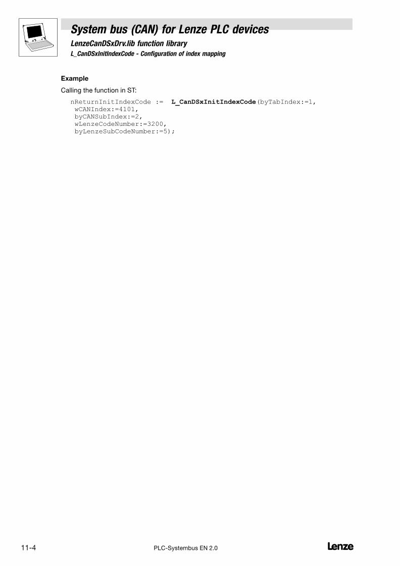
11.3 L_CanDSxInitIndexCode − Configuration of index mapping
System bus (CAN) for Lenze PLC devicesLenzeCanDSxDrv.lib function library
11−4 LPLC−Systembus EN 2.0
Example
Calling the function in ST:
nReturnInitIndexCode := L_CanDSxInitIndexCode(byTabIndex:=1, wCANIndex:=4101, byCANSubIndex:=2, wLenzeCodeNumber:=3200, byLenzeSubCodeNumber:=5);
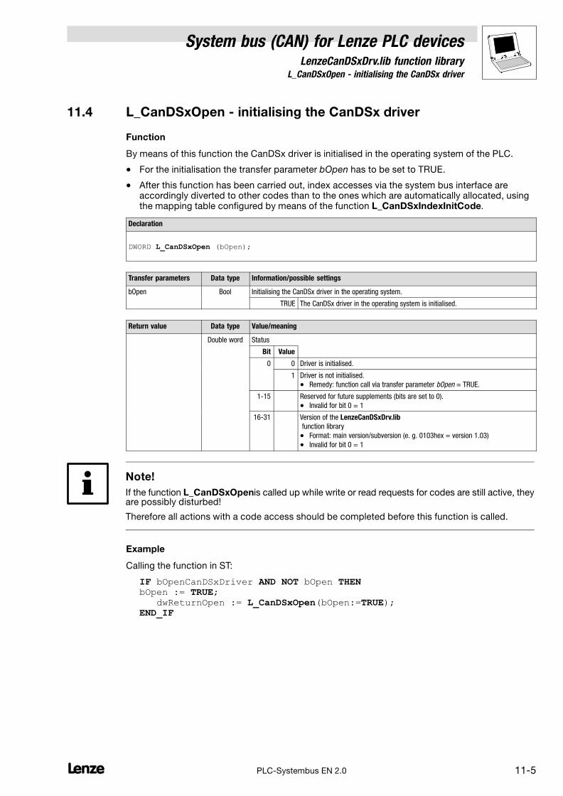
System bus (CAN) for Lenze PLC devicesLenzeCanDSxDrv.lib function library
11.4 L_CanDSxOpen − initialising the CanDSx driver
11−5L PLC−Systembus EN 2.0
11.4 L_CanDSxOpen − initialising the CanDSx driver
Function
By means of this function the CanDSx driver is initialised in the operating system of the PLC.
� For the initialisation the transfer parameter bOpen has to be set to TRUE.
� After this function has been carried out, index accesses via the system bus interface areaccordingly diverted to other codes than to the ones which are automatically allocated, usingthe mapping table configured by means of the function L_CanDSxIndexInitCode.
Declaration
DWORD L_CanDSxOpen (bOpen);
Transfer parameters Data type Information/possible settings
bOpen Bool Initialising the CanDSx driver in the operating system.
TRUE The CanDSx driver in the operating system is initialised.
Return value Data type Value/meaning
Double word Status
Bit Value
0 0 Driver is initialised.
1 Driver is not initialised.
� Remedy: function call via transfer parameter bOpen = TRUE.
1−15 Reserved for future supplements (bits are set to 0).
� Invalid for bit 0 = 1
16−31 Version of the LenzeCanDSxDrv.lib
function library
� Format: main version/subversion (e. g. 0103hex = version 1.03)
� Invalid for bit 0 = 1
Note!
If the function L_CanDSxOpenis called up while write or read requests for codes are still active, theyare possibly disturbed!
Therefore all actions with a code access should be completed before this function is called.
Example
Calling the function in ST:
IF bOpenCanDSxDriver AND NOT bOpen THENbOpen := TRUE; dwReturnOpen := L_CanDSxOpen(bOpen:=TRUE);END_IF
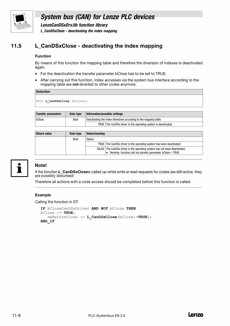
11.5 L_CanDSxClose − deactivating the index mapping
System bus (CAN) for Lenze PLC devicesLenzeCanDSxDrv.lib function library
11−6 LPLC−Systembus EN 2.0
11.5 L_CanDSxClose − deactivating the index mapping
Function
By means of this function the mapping table and therefore the diversion of indexes is deactivatedagain.
� For the deactivation the transfer parameter bClose has to be set to TRUE.
� After carrying out this function, index accesses via the system bus interface according to themapping table are not diverted to other codes anymore.
Declaration
BOOL L_CanDSxClose (bClose);
Transfer parameters Data type Information/possible settings
bClose Bool Deactivating the index diversions according to the mapping table.
TRUE The CanDSx driver in the operating system is deactivated.
Return value Data type Value/meaning
Bool Status
TRUE The CanDSx driver in the operating system has been deactivated.
FALSE The CanDSx driver in the operating system has not been deactivated.
� Remedy: function call via transfer parameter bClose = TRUE.
Note!
If the function L_CanDSxCloseis called up while write or read requests for codes are still active, theyare possibly disturbed!
Therefore all actions with a code access should be completed before this function is called.
Example
Calling the function in ST:
IF bCloseCanDSxDriver AND NOT bClose THENbClose := TRUE; dwReturnClose := L_CanDSxClose(bClose:=TRUE);END_IF
System bus (CAN) for Lenze PLC devicesLenzeCanDSxDrv.lib function library
11.6 L_CanDSxOpenHeartBeat − initialising a "Heartbeat"
11−7L PLC−Systembus EN 2.0
11.6 L_CanDSxOpenHeartBeat − initialising a "Heartbeat"
Function
In the CANopen communication profile (CiA DS301, version 4.01) two optional monitoringmechanisms for ensuring the function of system bus nodes are specified, "Heartbeat" and "NodeGuarding".
By means of this function, the "Heartbeat" monitoring mechanism of the CanDSx driver is initialised.
� For the initialisation the transfer parameter bOpen has to be set to TRUE.
� The actual monitoring is carried out using the L_CanDSxHeartBeat FB. (� 11−8)
� By means of the function L_CanDSxCloseHeartBeat you can deactivate the "Heartbeat"monitoring mechanism again. (� 11−10)
Note!
Using both monitoring mechanisms at the same is not permitted!
If a non−zero transmission cycle time for the "Heartbeat" message is configured for the node to bemonitored, the "Heartbeat" mechanism is used prior to the "Node Guarding" mechanism.
Declaration
BOOL L_CanDSxOpenHeartBeat(bOpen);
Transfer parameters Data type Information/possible settings
bOpen Bool Initialising the "Heartbeat" monitoring mechanism.
TRUE The "Heartbeat" monitoring mechanism of the CanDSx driver is initialised.
Return value Data type Value/meaning
Bool Status
TRUE The "Heartbeat" monitoring mechanism has been initialised.
FALSE A The "Heartbeat" monitoring mechanism has not been initialised.
– Remedy: function call with transfer parameter bOpen = TRUE.
or
B Beforehand the function L_CanDSxOpenNodeGuarding has been called("Node Guarding" is activated).
– Remedy: function call L_CanDSxCloseNodeGuarding with transferparameter bClose = TRUE (deactivate "Node Guarding").
Example
Calling the function in ST:
bReturnOpenHeartBeat := L_CanDSxOpenHeartBeat(bOpen:=TRUE);
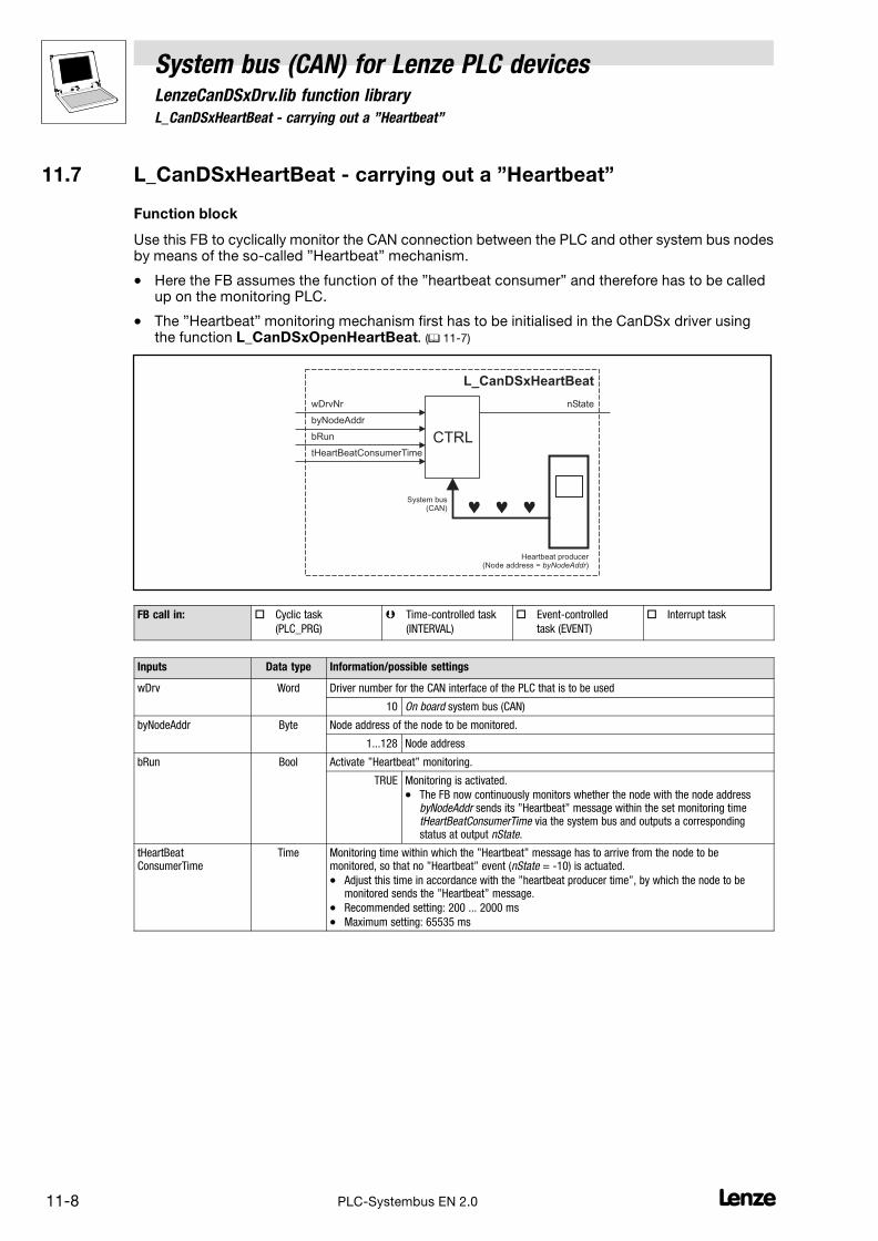
11.7 L_CanDSxHeartBeat − carrying out a "Heartbeat"
System bus (CAN) for Lenze PLC devicesLenzeCanDSxDrv.lib function library
11−8 LPLC−Systembus EN 2.0
11.7 L_CanDSxHeartBeat − carrying out a "Heartbeat"
Function block
Use this FB to cyclically monitor the CAN connection between the PLC and other system bus nodesby means of the so−called "Heartbeat" mechanism.
� Here the FB assumes the function of the "heartbeat consumer" and therefore has to be calledup on the monitoring PLC.
� The "Heartbeat" monitoring mechanism first has to be initialised in the CanDSx driver usingthe function L_CanDSxOpenHeartBeat. (� 11−7)
L_CanDSxHeartBeat
tHeartBeatConsumerTime
wDrvNr
byNodeAddr
bRun CTRL
nState
Heartbeat producer(Node address = )byNodeAddr
System bus(CAN) � � �
FB call in: � Cyclic task
(PLC_PRG)
� Time−controlled task
(INTERVAL)
� Event−controlled
task (EVENT)
� Interrupt task
Inputs Data type Information/possible settings
wDrv Word Driver number for the CAN interface of the PLC that is to be used
10 On board system bus (CAN)
byNodeAddr Byte Node address of the node to be monitored.
1...128 Node address
bRun Bool Activate "Heartbeat" monitoring.
TRUE Monitoring is activated.
� The FB now continuously monitors whether the node with the node addressbyNodeAddr sends its "Heartbeat" message within the set monitoring timetHeartBeatConsumerTime via the system bus and outputs a correspondingstatus at output nState.
tHeartBeatConsumerTime
Time Monitoring time within which the "Heartbeat" message has to arrive from the node to bemonitored, so that no "Heartbeat" event (nState = −10) is actuated.
� Adjust this time in accordance with the "heartbeat producer time", by which the node to bemonitored sends the "Heartbeat" message.
� Recommended setting: 200 ... 2000 ms
� Maximum setting: 65535 ms
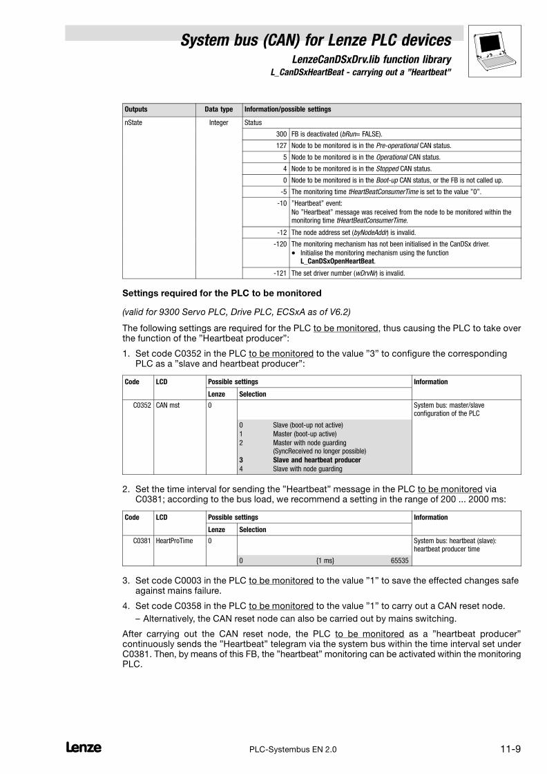
System bus (CAN) for Lenze PLC devicesLenzeCanDSxDrv.lib function library
11.7 L_CanDSxHeartBeat − carrying out a "Heartbeat"
11−9L PLC−Systembus EN 2.0
Outputs Data type Information/possible settings
nState Integer Status
300 FB is deactivated (bRun= FALSE).
127 Node to be monitored is in the Pre−operational CAN status.
5 Node to be monitored is in the Operational CAN status.
4 Node to be monitored is in the Stopped CAN status.
0 Node to be monitored is in the Boot−up CAN status, or the FB is not called up.
−5 The monitoring time tHeartBeatConsumerTime is set to the value "0".
−10 "Heartbeat" event:
No "Heartbeat" message was received from the node to be monitored within themonitoring time tHeartBeatConsumerTime.
−12 The node address set (byNodeAddr) is invalid.
−120 The monitoring mechanism has not been initialised in the CanDSx driver.
� Initialise the monitoring mechanism using the functionL_CanDSxOpenHeartBeat.
−121 The set driver number (wDrvNr) is invalid.
Settings required for the PLC to be monitored
(valid for 9300 Servo PLC, Drive PLC, ECSxA as of V6.2)
The following settings are required for the PLC to be monitored, thus causing the PLC to take overthe function of the "Heartbeat producer":
1. Set code C0352 in the PLC to be monitored to the value "3" to configure the correspondingPLC as a "slave and heartbeat producer":
Code LCD Possible settings Information
Lenze Selection
C0352 CAN mst 0 System bus: master/slaveconfiguration of the PLC
0 Slave (boot−up not active)
1 Master (boot−up active)
2 Master with node guarding(SyncReceived no longer possible)
3 Slave and heartbeat producer
4 Slave with node guarding
2. Set the time interval for sending the "Heartbeat" message in the PLC to be monitored viaC0381; according to the bus load, we recommend a setting in the range of 200 ... 2000 ms:
Code LCD Possible settings Information
Lenze Selection
C0381 HeartProTime 0 System bus: heartbeat (slave):heartbeat producer time
0 {1 ms} 65535
3. Set code C0003 in the PLC to be monitored to the value "1" to save the effected changes safeagainst mains failure.
4. Set code C0358 in the PLC to be monitored to the value "1" to carry out a CAN reset node.
– Alternatively, the CAN reset node can also be carried out by mains switching.
After carrying out the CAN reset node, the PLC to be monitored as a "heartbeat producer"continuously sends the "Heartbeat" telegram via the system bus within the time interval set underC0381. Then, by means of this FB, the "heartbeat" monitoring can be activated within the monitoringPLC.

11.8 L_CanDSxCloseHeartBeat − deactivating the "Heartbeat"
System bus (CAN) for Lenze PLC devicesLenzeCanDSxDrv.lib function library
11−10 LPLC−Systembus EN 2.0
11.8 L_CanDSxCloseHeartBeat − deactivating the "Heartbeat"
Function
By means of this function, the "Heartbeat" monitoring mechanism of the CanDSx driver isdeactivated again.
� For the deactivation the transfer parameter bClose has to be set to TRUE.
Declaration
BOOL L_CanDSxCloseHeartBeat(bClose);
Transfer parameters Data type Information/possible settings
bClose Bool Deactivating the "Heartbeat" monitoring mechanism.
TRUE The "Heartbeat" monitoring mechanism of the CanDSx driver in the operatingsystem is deactivated.
Return value Data type Value/meaning
Bool Status
TRUE The "Heartbeat" monitoring mechanism of the CanDSx driver has beendeactivated.
FALSE The "Heartbeat" monitoring mechanism of the CanDSx driver has not beendeactivated.
� Remedy: function call via transfer parameter bClose = TRUE.
Example
Calling the function in ST:
bReturnCloseHeartBeat := L_CanDSxCloseHeartBeat(bClose:=TRUE);
System bus (CAN) for Lenze PLC devicesLenzeCanDSxDrv.lib function library
11.9 L_CanDSxOpenNodeGuarding − initialising the "Node Guarding"
11−11L PLC−Systembus EN 2.0
11.9 L_CanDSxOpenNodeGuarding − initialising the "Node Guarding"
Function
In the CANopen communication profile (CiA DS301, version 4.01) two optional monitoringmechanisms for ensuring the function of system bus nodes are specified, "Heartbeat" and "NodeGuarding".
By means of this function the "Node Guarding" monitoring mechanism of the CanDSx driver isinitialised.
� For the initialisation, the transfer parameter bOpen has to be set to TRUE.
� The actual monitoring is carried out using the L_CanDSxNodeGuarding FB. (� 11−12)
� By means of the function L_CanDSxCloseNodeGuarding you can deactivate the "NodeGuarding" monitoring mechanism again. (� 11−15)
Note!
Using both monitoring mechanisms at the same is not permitted!
If a non−zero transmission cycle time for the "Heartbeat" message is configured for the node to bemonitored, the "Heartbeat" mechanism is used prior to the "Node Guarding" mechanism.
Declaration
BOOL L_CanDSxOpenNodeGuarding(bOpen);
Transfer parameters Data type Information/possible settings
bOpen Bool Initialising the "Node Guarding" monitoring mechanism
TRUE The "Node Guarding" monitoring mechanism of the CanDSx driver is initialised.
return value Data type Value/meaning
Bool Status
TRUE The "Node Guarding" monitoring mechanism has been initialised.
FALSE A The "Node Guarding" monitoring mechanism has not been initialised.
– Remedy: function call with transfer parameter bOpen = TRUE.
or
B The PLC is not configured as "Master with Node Guarding" anymore.
– Remedy: set code C352 to the value "2" to configure the PLC as "Masterwith Node Guarding".
Example
Calling the function in ST:
bReturnOpenNodeGuarding := L_CanDSxOpenNodeGuarding(bOpen:=TRUE);
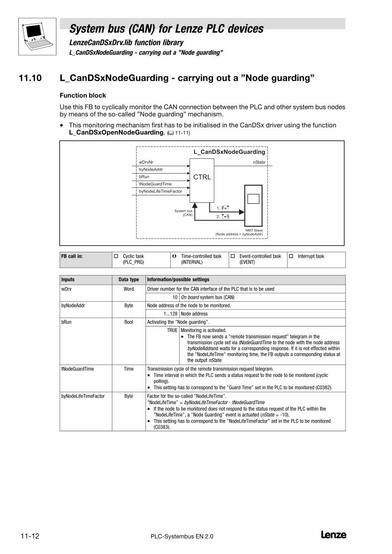
11.10 L_CanDSxNodeGuarding − carrying out a "Node guarding"
System bus (CAN) for Lenze PLC devicesLenzeCanDSxDrv.lib function library
11−12 LPLC−Systembus EN 2.0
11.10 L_CanDSxNodeGuarding − carrying out a "Node guarding"
Function block
Use this FB to cyclically monitor the CAN connection between the PLC and other system bus nodesby means of the so−called "Node guarding" mechanism.
� This monitoring mechanism first has to be initialised in the CanDSx driver using the functionL_CanDSxOpenNodeGuarding. (� 11−11)
L_CanDSxNodeGuarding
tNodeGuardTime
wDrvNr
byNodeAddr
bRun CTRL
nState
NMT Slave(Node address = )byNodeAddr
System bus(CAN)
�
byNodeLifeTimeFactor
1.
2. �
FB call in: � Cyclic task (PLC_PRG)
� Time−controlled task(INTERVAL)
� Event−controlled task(EVENT)
� Interrupt task
Inputs Data type Information/possible settings
wDrv Word Driver number for the CAN interface of the PLC that is to be used
10 On board system bus (CAN)
byNodeAddr Byte Node address of the node to be monitored.
1...128 Node address
bRun Bool Activating the "Node guarding".
TRUE Monitoring is activated.
� The FB now sends a "remote transmission request" telegram in thetransmission cycle set via tNodeGuardTime to the node with the node addressbyNodeAddrand waits for a corresponding response. If it is not effected withinthe "NodeLifeTime" monitoring time, the FB outputs a corresponding status atthe output nState.
tNodeGuardTime Time Transmission cycle of the remote transmission request telegram.
� Time interval in which the PLC sends a status request to the node to be monitored (cyclicpolling).
� This setting has to correspond to the "Guard Time" set in the PLC to be monitored (C0382).
byNodeLifeTimeFactor Byte Factor for the so−called "NodeLifeTime".
"NodeLifeTime" = byNodeLifeTimeFactor � tNodeGuardTime
� If the node to be monitored does not respond to the status request of the PLC within the"NodeLifeTime", a "Node Guarding" event is actuated (nState = −10).
� This setting has to correspond to the "NodeLifeTimeFactor" set in the PLC to be monitored(C0383).
System bus (CAN) for Lenze PLC devicesLenzeCanDSxDrv.lib function library
11.10 L_CanDSxNodeGuarding − carrying out a "Node guarding"
11−13L PLC−Systembus EN 2.0
Outputs Data type Information/possible settings
nState Integer Status
300 FB is deactivated (bRun= FALSE).
127 Node to be monitored is in the Pre−operational CAN status.
5 Node to be monitored is in the Operational CAN status.
4 Node to be monitored is in the Stopped CAN status.
0 Node to be monitored is in the Boot−up CAN status, or the FB is not called up.
−5 The tNodeGuardTime monitoring time or the factor byNodeLifeTimeFactor is set tothe value "0".
−9 Response of the node to be monitored is invalid.
−10 "Node Guarding" event:
No status response from the node to be monitored was received within the"NodeLifeTime" monitoring time.
−12 The set node address (byNodeAddr) is invalid.
−120 The monitoring mechanism has not been initialised in the CanDSx driver.
� Initialise the monitoring mechanism using the functionL_CanDSxOpenNodeGuarding.
−121 The set driver number (wDrvNr) is invalid.
Settings required for the PLC to be monitored
(valid for 9300 Servo PLC, Drive PLC, ECSxA as of V6.2)
The following settings are required for the PLC to be monitored, thus causing the PLC to take overthe function of the "Node Guarding Slave":
1. Set code C0352 in the PLC to be monitored to the value "4" to configure the correspondingPLC as a "Slave with Node Guarding":
Code LCD Possible settings Information
Lenze Selection
C0352 CAN mst 0 System bus: master/slaveconfiguration of the PLC
0 Slave (boot−up not active)
1 Master (boot−up active)
2 Master with Node Guarding(SyncReceived no longer possible)
3 Slave and heartbeat producer
4 Slave with Node Guarding
2. Set the time interval for the status enquiry by the master in the PLC to be monitored viaC0382. This value has to correspond to the setting at the FB input tNodeGuardTime in themonitoring PLC:
Code LCD Possible settings Information
Lenze Selection
C0382 GuardTime 0 System bus: Node Guarding (slave):NodeGuardTime
0 {1 ms} 65535
3. Set the "Node Guarding Master" in the monitoring PLC with C0352/0 = 2.
11.10 L_CanDSxNodeGuarding − carrying out a "Node guarding"
System bus (CAN) for Lenze PLC devicesLenzeCanDSxDrv.lib function library
11−14 LPLC−Systembus EN 2.0
4. Set the factor for the "NodeLifeTime" monitoring time via C0383 in the PLC to be monitored.This value has to correspond to the setting at the FB input byNodeLifeTimeFactor in themonitoring PLC:
Code LCD Possible settings Information
Lenze Selection
C0383 LifeTimeFact. 0 System bus: Node Guarding (slave):NodeLifeTimeFactor
0 {1} 255
Tip!
From the settings for the "NodeGuardTime" (C0382) and the "NodeLifeTimeFactor" (C0383) in thePLC to be monitored, the so−called "NodeLifeTime" results:
NodeLifeTime = NodeGuardTime(C0382) � NodeLifeTimeFactor (C0383)
� If the PLC to be monitored does not receive a status enquiry from the monitoring PLC withinthis "NodeLifeTime", a so−called "Life Guarding" event is actuated in the PLC to bemonitored.
5. Set the desired response by which the PLC to be monitored is to react to a "Life GuardingEvent" via C0384 in the PLC to be monitored:
Code LCD Possible settings Information
Lenze Selection
C0384 Err NodeGuard 3 System bus: Node Guarding (slave):response to a "Life Guard" event.
0 TRIP
1 Message
2 Warning
3 Off
4 Fail−QSP
6. Set code C0003 in the PLC to be monitored to the value "1" to save the effected changes in amanner safe against mains failure.
7. Set code C0358 in the PLC to be monitored to the value "1" to carry out a CAN reset node.
– Alternatively, the CAN reset node can also be carried out by mains switching.
After the CAN reset node has been carried out, the PLC to be monitored is configured as "nodeguarding slave", and monitoring in the "node guarding master" can be activated using this FB.

System bus (CAN) for Lenze PLC devicesLenzeCanDSxDrv.lib function library
11.11 L_CanDSxCloseNodeGuarding − deactivating the "Node Guarding"
11−15L PLC−Systembus EN 2.0
11.11 L_CanDSxCloseNodeGuarding − deactivating the "Node
Guarding"
Function
By means of this function, the "Node Guarding" monitoring mechanism of the CanDSx driver isdeactivated again.
� For the deactivation the transfer parameter bClose has to be set to TRUE.
Declaration
BOOL L_CanDSxCloseNodeGuarding (bClose);
Transfer parameters Data type Information/possible settings
bClose Bool Deactivating the "Node Guarding" monitoring mechanism
TRUE The "Node Guarding" monitoring mechanism of the CanDSx driver is deactivated.
Return value Data type Value/meaning
Bool Status
TRUE The "Node Guarding" monitoring mechanism of the CanDSx driver has beendeactivated.
FALSE The "Node Guarding" monitoring mechanism of the CanDSx driver has not beendeactivated.
� Remedy: function call via transfer parameter bClose = TRUE.
Example
Calling the function in ST:
bReturnCloseNodeGuarding := L_CanDSxCloseNodeGuarding(bClose:=TRUE);

11.11 L_CanDSxCloseNodeGuarding − deactivating the "Node Guarding"
System bus (CAN) for Lenze PLC devicesLenzeCanDSxDrv.lib function library
11−16 LPLC−Systembus EN 2.0

System bus (CAN) for Lenze PLC devicesIndex
12−1L PLC−Systembus EN 2.0
12 Index
A
Addressing parameters, 2−13
Axis synchronisation, 7−23
B
Baud rate
AIF interface, 4−1
CAN interface, 3−1
CAN−AUX interface, 6−1
FIF interface, 5−1
Boot−up
AIF interface, 4−2
CAN interface, 3−2
CAN−AUX interface, 6−2
FIF interface, 5−2
Bus load
CAN interface, 3−15
CAN−AUX interface, 6−13
FIF interface, 5−13
Bus off, AIF interface, 4−9
Bus−off
CAN interface, 3−11
CAN−AUX interface, 6−9
FIF interface, 5−9
C
C0350, 3−3
C0351, 3−1
C0352, 3−2
C0353, 3−4
C0354, 3−4
C0355, 3−5
C0356, 3−2 , 3−6
C0357, 3−11
C0358, 3−8 , 4−8
C0359, 3−13
C0360, 3−14
C0361, 3−15
C0363, 7−26
C0366, 3−7 , 7−26
C0367, 3−7 , 7−26
C0368, 3−7 , 7−26
C0369, 3−7 , 7−26
C0591, 3−11
C0592, 3−11
C0593, 3−11
C0595, 3−11
C0608, 10−4
C0609, 10−4
C1120, 7−23
C1121, 7−25
C1122, 7−25
C1123, 7−25
C2121, 4−10
C2350, 4−3
C2351, 4−1
C2352, 4−2
C2353, 4−4
C2354, 4−4
C2355, 4−5
C2356, 4−2 , 4−6 , 4−7
C2357, 4−8
C2367, 4−7
C2368, 4−7
C2375, 4−7
C2382, 4−8 , 4−9
C2450, 5−3 , 6−3
C2451, 5−1 , 6−1
C2452, 5−2 , 6−2
C2453, 5−4 , 6−4
C2454, 5−4 , 6−4
C2455, 5−5 , 6−5
C2456, 5−2 , 5−6 , 6−2 , 6−6
C2457, 5−9 , 6−9
C2458, 5−8 , 6−8
C2459, 5−11 , 6−11
C2460, 5−12 , 6−12
C2461, 5−13 , 6−13
C2466, 5−7 , 6−7
C2467, 5−7 , 6−7
C2468, 5−7 , 6−7
C2469, 5−7 , 6−7
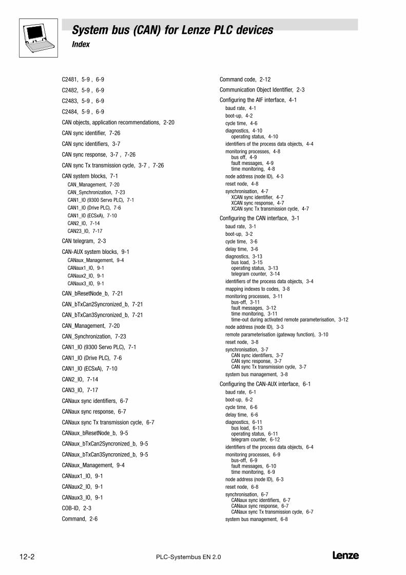
System bus (CAN) for Lenze PLC devicesIndex
12−2 LPLC−Systembus EN 2.0
C2481, 5−9 , 6−9
C2482, 5−9 , 6−9
C2483, 5−9 , 6−9
C2484, 5−9 , 6−9
CAN objects, application recommendations, 2−20
CAN sync identifier, 7−26
CAN sync identifiers, 3−7
CAN sync response, 3−7 , 7−26
CAN sync Tx transmission cycle, 3−7 , 7−26
CAN system blocks, 7−1
CAN_Management, 7−20
CAN_Synchronization, 7−23
CAN1_IO (9300 Servo PLC), 7−1
CAN1_IO (Drive PLC), 7−6
CAN1_IO (ECSxA), 7−10
CAN2_IO, 7−14
CAN23_IO, 7−17
CAN telegram, 2−3
CAN−AUX system blocks, 9−1
CANaux_Management, 9−4
CANaux1_IO, 9−1
CANaux2_IO, 9−1
CANaux3_IO, 9−1
CAN_bResetNode_b, 7−21
CAN_bTxCan2Syncronized_b, 7−21
CAN_bTxCan3Syncronized_b, 7−21
CAN_Management, 7−20
CAN_Synchronization, 7−23
CAN1_IO (9300 Servo PLC), 7−1
CAN1_IO (Drive PLC), 7−6
CAN1_IO (ECSxA), 7−10
CAN2_IO, 7−14
CAN3_IO, 7−17
CANaux sync identifiers, 6−7
CANaux sync response, 6−7
CANaux sync Tx transmission cycle, 6−7
CANaux_bResetNode_b, 9−5
CANaux_bTxCan2Syncronized_b, 9−5
CANaux_bTxCan3Syncronized_b, 9−5
CANaux_Management, 9−4
CANaux1_IO, 9−1
CANaux2_IO, 9−1
CANaux3_IO, 9−1
COB−ID, 2−3
Command, 2−6
Command code, 2−12
Communication Object Identifier, 2−3
Configuring the AIF interface, 4−1
baud rate, 4−1
boot−up, 4−2
cycle time, 4−6
diagnostics, 4−10 operating status, 4−10
identifiers of the process data objects, 4−4
monitoring processes, 4−8 bus off, 4−9 fault messages, 4−9 time monitoring, 4−8
node address (node ID), 4−3
reset node, 4−8
synchronisation, 4−7 XCAN sync identifier, 4−7 XCAN sync response, 4−7 XCAN sync Tx transmission cycle, 4−7
Configuring the CAN interface, 3−1
baud rate, 3−1
boot−up, 3−2
cycle time, 3−6
delay time, 3−6
diagnostics, 3−13 bus load, 3−15 operating status, 3−13 telegram counter, 3−14
identifiers of the process data objects, 3−4
mapping indexes to codes, 3−8
monitoring processes, 3−11 bus−off, 3−11 fault messages, 3−12 time monitoring, 3−11 time−out during activated remote parameterisation, 3−12
node address (node ID), 3−3
remote parameterisation (gateway function), 3−10
reset node, 3−8
synchronisation, 3−7 CAN sync identifiers, 3−7 CAN sync response, 3−7 CAN sync Tx transmission cycle, 3−7
system bus management, 3−8
Configuring the CAN−AUX interface, 6−1
baud rate, 6−1
boot−up, 6−2
cycle time, 6−6
delay time, 6−6
diagnostics, 6−11 bus load, 6−13 operating status, 6−11 telegram counter, 6−12
identifiers of the process data objects, 6−4
monitoring processes, 6−9 bus−off, 6−9 fault messages, 6−10 time monitoring, 6−9
node address (node ID), 6−3
reset node, 6−8
synchronisation, 6−7 CANaux sync identifiers, 6−7 CANaux sync response, 6−7 CANaux sync Tx transmission cycle, 6−7
system bus management, 6−8
System bus (CAN) for Lenze PLC devicesIndex
12−3L PLC−Systembus EN 2.0
Configuring the FIF interface, 5−1
baud rate, 5−1
boot−up, 5−2
cycle time, 5−6
delay time, 5−6
diagnostics, 5−11 bus load, 5−13 operating status, 5−11
diagnostics , telegram counter, 5−12
identifiers of the process data objects, 5−4
monitoring processes, 5−9 bus−off, 5−9 fault messages, 5−10 time monitoring, 5−9
node address (node ID), 5−3
reset node, 5−8
synchronisation, 5−7 FIF−CAN sync identifier, 5−7 FIF−CAN sync response, 5−7 FIF−CAN sync Tx transmission cycle, 5−7
system bus management, 5−8
Correction value of the phase controller, 7−26
Cycle time
AIF interface, 4−6
CAN interface, 3−6
CAN−AUX interface, 6−6
FIF interface, 5−6
D
Data of the parameter, 2−14
Delay time
CAN interface, 3−6
CAN−AUX interface, 6−6
FIF interface, 5−6
Device address, 2−6
Diagnostics
AIF interface, 4−10 operating status, 4−10
CAN interface, 3−13 bus load, 3−15 operating status, 3−13 telegram counter, 3−14
CAN−AUX interface, 6−11 bus load, 6−13 operating status, 6−11 telegram counter, 6−12
FIF interface, 5−11 , 5−12 bus load, 5−13 operating status, 5−11
E
Error Response, 2−12
F
Fault messages, 6−10
AIF interface, 4−9
CAN interface, 3−12
CAN−AUX interface, 6−10
FIF interface, 5−10
FIF−CAN sync identifier, 5−7
FIF−CAN sync response, 5−7
FIF−CAN sync Tx transmission cycle, 5−7
FIF−CAN system blocks, 8−1
FIF_CAN_Management, 8−4
FIF_CAN1_IO, 8−1
FIF_CAN2_IO, 8−1
FIF_CAN3_IO, 8−1
FIF_CAN_bResetNode_b, 8−5
FIF_CAN_Management, 8−4
FIF_CAN1_IO, 8−1
FIF_CAN2_IO, 8−1
FIF_CAN3_IO, 8−1
Forced transmission, 10−11
Free CAN objects, 2−19
G
Gateway function, CAN interface, 3−10
H
Heartbeat, 2−21
I
Identifier, 2−3 , 2−10
Identifiers, 2−11
AIF interface, 4−4
CAN interface, 3−4
CAN−AUX interface, 6−4
FIF interface, 5−4
Index, 2−13
L
L_CanClose, 10−5
L_CanGetRelocCobId, 10−7
L_CanGetStatus, 10−6
L_CanInit, 10−2
L_CanPdoReceive, 10−12
L_CanPdoTransmit, 10−8
L_ParWrite, 10−10
System bus (CAN) for Lenze PLC devicesIndex
12−4 LPLC−Systembus EN 2.0
M
Mapping indexes to codes, CAN interface, 3−8
Monitoring mechanisms, 2−21
"Heartbeat", 2−21
"Node Guarding", 2−22
Monitoring processes
AIF interface, 4−8 bus off, 4−9 fault messages, 4−9 time monitoring, 4−8
CAN interface, 3−11 bus−off, 3−11 fault messages, 3−12 time monitoring, 3−11 time−out during activated remote parameterisation, 3−12
CAN−AUX interface, 6−9 bus−off, 6−9 fault messages, 6−10 time monitoring, 6−9
FIF interface, 5−9 bus−off, 5−9 fault messages, 5−10 time monitoring, 5−9
N
Network management (NMT), 2−6
command, 2−6
device address, 2−6
Netwotk status, 2−6
Node address (node ID)
AIF interface, 4−3
CAN interface, 3−3
CAN−AUX interface, 6−3
FIF interface, 5−3
Node Guarding, 2−22
Node ID, 2−3 , 6−3
P
Parameter data, 2−5 , 2−11
addressing (index/subindex), 2−13
command code, 2−12
data format, 2−14
identifiers, 2−11
reading parameters, 2−17
telegram structure, 2−11
transmission, 2−11
writing parameters, 2−15
PDOs, 2−5
Phase displacement, 7−25
Process data, 2−5
identifier, 2−10
sync telegram, 2−9
telegram structure, 2−10
transmission, 2−7
user data, 2−10
Process data channels, 2−7
Process Data Objects, 2−5
R
Read request, 2−12
Read response, 2−12
Reading parameters, 2−17
Receive status, 10−13
Remote parameterisation (gateway function), CAN interface,3−10
Reset node
AIF interface, 4−8
CAN interface, 3−8
CAN−AUX interface, 6−8
FIF interface, 5−8
S
Safety information, layout, More notes, 1−4
Safety instructions, layout, warning of material damage, 1−4
SDOs, 2−5
Service Data Objects, 2−5
Subindex, 2−13
Sync telegram, 2−9
Synchronisation
AIF interface, 4−7
CAN interface, 3−7
CAN sync identifiers, 3−7
CAN sync response, 3−7
CAN sync Tx transmission cycle, 3−7
CAN−AUX interface, 6−7
CANaux sync identifiers, 6−7
CANaux sync response, 6−7
CANaux sync Tx transmission cycle, 6−7
FIF interface, 5−7
FIF−CAN sync identifier, 5−7
FIF−CAN sync response, 5−7
FIF_CAN sync Tx transmission cycle, 5−7
XCAN sync identifier, 4−7
XCAN sync response, 4−7
XCAN sync Tx transmission cycle, 4−7
Synchronisation cycle, 7−25
Synchronisation time, 7−24

System bus (CAN) for Lenze PLC devicesIndex
12−5L PLC−Systembus EN 2.0
System bus (CAN), 2−1
CAN objects, application recommendations, 2−20
cycle timeAIF interface, 4−6 CAN interface, 3−6 CAN−AUX interface, 6−6 FIF interface, 5−6
delay timeCAN interface, 3−6 CAN−AUX interface, 6−6 FIF interface, 5−6
diagnosticsAIF interface, 4−10 CAN interface, 3−13 CAN−AUX interface, 6−11 FIF interface, 5−11
free CAN objects, 2−19
identification of the nodes, 2−3
identifier, 2−3
identifiersAIF interface, 4−4 CAN interface, 3−4 CAN−AUX interface, 6−4 FIFterface, 5−4
interfaces for system bus connection, 2−2 configuring the AIF interface, 4−1 configuring the CAN−AUX interface, 6−1
interfaces for systerm bus connection, Configuring the FIFinterface, 5−1
interfaces for the system bus connection, configuring the CANinterface, 3−1
mapping indexes to codes, CAN interface, 3−8
monitoring mechanisms, 2−21 "Heartbeat", 2−21 "Node Guarding", 2−22
monitoring processesAIF interface, 4−8 CAN interface, 3−11 CAN−AUX interface, 6−9 FIF interface, 5−9
network management (NMT), 2−6 command, 2−6 device address, 2−6
operating statusAIF interface, 4−10 CAN interface, 3−13 CAN−AUX interface, 6−11 FIF interface, 5−11
parameter dataaddressing (index/subindex), 2−13 command code, 2−12 data format, 2−14 identifiers, 2−11 reading parameters, 2−17 telegram structure, 2−11 transmission, 2−11 writing parameters, 2−15
process dataidentifier, 2−10 sync telegram, 2−9 telegram structure, 2−10 transmission, 2−7 user data, 2−10
remote parameterisation (gateway function), CAN interface,3−10
reset nodeAIF interface, 4−8 CAN interface, 3−8 CAN−AUX interface, 6−8 FIF interface, 5−8
synchronisationAIF interface, 4−7 CAN interface, 3−7 CAN−AUX interface, 6−7 FIF interface, 5−7
system bus managementCAN interface, 3−8 CAN−AUX interface, 6−8 FIF interface, 5−8
telegram structure, 2−3
user data, 2−5
System bus management
CAN, 7−20
CAN interface, 3−8
CAN−AUX, 8−4 , 9−4
CAN−AUX interface, 6−8
FIF interface, 5−8
T
Telegram counter
CAN interface, 3−14
CAN−AUX interface, 6−12
FIF interface, 5−12
Term definitions, 1−4
Time monitoring
AIF interface, 4−8
CAN interface, 3−11
CAN−AUX interface, 6−9
FIF interface, 5−9
Time slot, 7−25
Time−out during activated remote paramterisation, CANinterface, 3−12
Transmission
parameter data, 2−11
process data, 2−7
Transmit request memory, 10−10
Transmit status, 10−9
U
User data, 2−5 , 2−10
V
Version identifiers of the function library, 10−1 , 11−2
W
Write request, 2−12
Write response, 2−12
Writing parameters, 2−15

System bus (CAN) for Lenze PLC devicesIndex
12−6 LPLC−Systembus EN 2.0
X
XCAN sync identifier, 4−7
XCAN sync response, 4−7
XCAN sync Tx transmission cycle, 4−7