software for electrical engineering analysis and … · ^electrical engineering department,...
TRANSCRIPT

A software package for analysis of circular
corrugated horns in their operative
environment
G. Pelosi(% R. CocciolF), R.
Electrical Engineering Department, University of Florence, Via C,
Lombroso 6/17, 50134 Firenze, Italy
Electrical Engineering Department, University of California, Los
CA
Abstract
A hybrid method for the analysis of the interaction between circular corrugatedhorns and conducting structures usually present in their operative environment isproposed. The method is based on the application of a particular formulation ofthe equivalence principle that subdivides the original problem into an exteriorand an interior one. The former is formulated by using a moment method basedon a Combined Field Integral Equation (CFIE), the latter by employing theMode Matching technique. The Green's function in the kernel of the CFIE for theformulation of the exterior problem is modified to take into account the presenceof conducting structures placed nearby the corrugated horn. Numerical resultsshowing the level of field on the horn opening due to unwanted interactions in adual Gregorian antenna system are reported.
1 Introduction
Circular corrugated horns are often used as feeders in modern reflector high-performance antenna systems because of their very good characteristics in termof high copolar pattern symmetry [1-2], low-level of cross polarization [3] andgood impedance matching [4]. Because of these attractive features, corrugatedhorns have been extensively studied and many efforts have been directed towardsthe development of efficient methods for their analysis and design [4].
One of the most used analysis method is the Mode-Matching (MM) [5]which provides a very accurate model of the field inside the horn, at the expenseof computational cost. Among the advantages of the MM, its great flexibility isprobably the most important since it allows to analyze horns with corrugations
Transactions on Engineering Sciences vol 22 © 1999 WIT Press, www.witpress.com, ISSN 1743-3533

36 Software for Electrical Engineering Analysis and Design
having arbitrarily varying depth and width. This feature is particularly importantfor horns used in space applications where excitation of higher order modes inmultimode horns as well as matching the feeder to the beam forming networkmust be achieved using only a suitable design of the corrugations shape. In fact,for this kind of application is desirable to avoid using dielectric materials.
Because this method is suitable for the analysis of the interior part only ofthe horn, many efforts have been focused towards the hybridization of MM withintegral formulations which can take into account also the external geometry ofthe horn [6-9]. However, no effort has been done so far to include in the analysisinteractions between the horn and perfectly conducting structures often present inits operative environment. This aspect of the analysis is particularly importantwhen the horn is used as feeder in a reflector antenna system and parabolicreflectors and struts constitute an important part of the horn operativeenvironment.
Aim of this work is to present a software package for the analysis and designof circular corrugated horns that can also evaluate the level of unwanted couplingbetween the horn and nearby conducting structures with characteristic dimensionslarge with respect to the wavelength. The package implements a hybrid methodthat is an extension of that presented in [8-9] for the analysis and optimization ofcircular corrugated horns radiating in free space. The effects of nearby structureson the horn performance have been estimated by using a perturbative approach inconjunction with the Uniform Theory of Diffraction (UTD) [10]. The UTD isemployed to modify the kernel of the integral equation used to formulate theexterior part of the problem.
This approach has the advantage of requiring a limited number of unknownsand it provides a first order correction to results obtained considering the hornisolated. On the other hand, its validity is limited to the case of perfectlyconducting objects with dimensions and distance from the horn of the same orderof wavelength. Indeed, this is not a limitation for the analysis of reflector antennasystems using corrugated horns as feeders.
The paper is organized as follows: the analysis method implemented in thesoftware package is described in details in Section 2; both the rigorousformulation and the perturbative approach actually implemented are considered.Numerical data relative to a dual Gregorian Rotatable Coverage satellite antennaare presented in Section 3. Finally, conclusions are drawn in Section 4.
2 Analysis Method
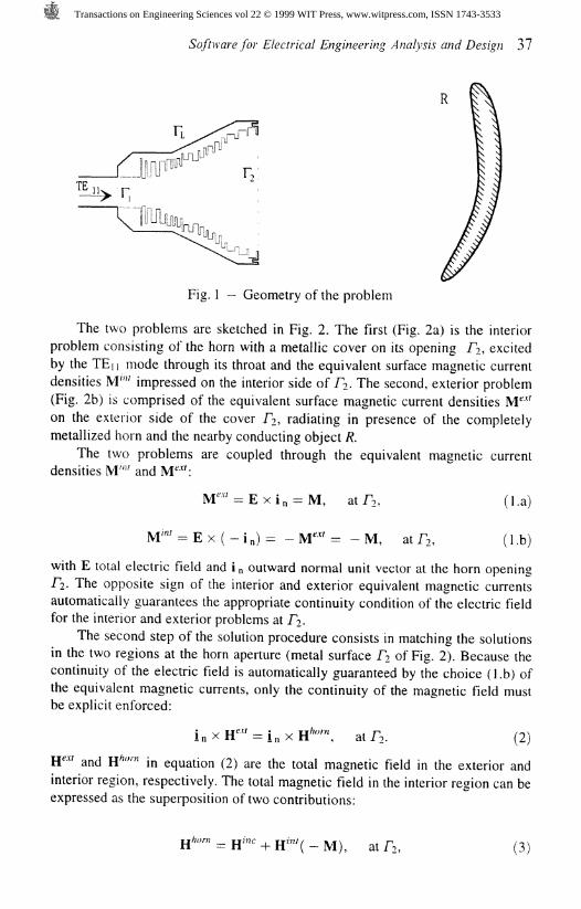
The longitudinal section of a transverse corrugated circular horn and a metallicobject placed nearby is sketched in Fig. 1. The analysis of this problem is carriedon using a two-step technique. In the first step, a particular formulation of theequivalence theorem [11,12] is used to subdivide the original problem into twoseparate but coupled problems.
Transactions on Engineering Sciences vol 22 © 1999 WIT Press, www.witpress.com, ISSN 1743-3533
Software for Electrical Engineering Analysis and Design 37
f\
Fig. 1 - Geometry of the problem
The two problems are sketched in Fig. 2. The first (Fig. 2a) is the interiorproblem consisting of the horn with a metallic cover on its opening T?, excitedby the TEn mode through its throat and the equivalent surface magnetic currentdensities M"" impressed on the interior side of PI. The second, exterior problem(Fig. 2b) is comprised of the equivalent surface magnetic current densities IVT"on the exterior side of the cover f?, radiating in presence of the completelymetallized horn and the nearby conducting object R.
The two problems are coupled through the equivalent magnetic currentdensities MT' and M<*':
M"" = E x ( - in) = - &T" = -M,at
with E total electric field and i „ outward normal unit vector at the horn opening/2. The opposite sign of the interior and exterior equivalent magnetic currentsautomatically guarantees the appropriate continuity condition of the electric fieldfor the interior and exterior problems at I"?.
The second step of the solution procedure consists in matching the solutionsin the two regions at the horn aperture (metal surface A of Fig. 2). Because thecontinuity of the electric field is automatically guaranteed by the choice (l.b) ofthe equivalent magnetic currents, only the continuity of the magnetic field mustbe explicit enforced:
jhorn at IV (2)
H"' and H'""" in equation (2) are the total magnetic field in the exterior andinterior region, respectively. The total magnetic field in the interior region can beexpressed as the superposition of two contributions:
at A, (3)
Transactions on Engineering Sciences vol 22 © 1999 WIT Press, www.witpress.com, ISSN 1743-3533

3 8 Software for Electrical Engineering Analysis and Design
a) interior problem
b) exterior problem
Fig. 2 — The original problem is subdivided into an interior (a) and an exteriorone (b).
where W™ is the magnetic field produced over the horn opening by the TEnmode fed through the input port FI, while H*™' is the contribution due to theinterior equivalent magnetic current distribution — M The magnetic fieldcontinuity condition yields the integrodifferential equation:
x H"'(M) + i n x H""(M) = i at (4)
that can be solved for the unknown equivalent magnetic current. The applicationof the standard weighted residual method to equation (4) transforms thatintegrodifferential equation into the linear system of equations:
[¥"' + ¥''"'] [V] = [I], (5)
whose solution gives the equivalent magnetic current distribution M Theknowledge of M immediately gives the actual electric field distribution over thehorn aperture in presence of the conducting object (R in Fig. 1). In equation (5),[V] is the column vector of the unknown coefficients of the basis functions {M/,j = 1,N} used to express the equivalent current distribution M, [I] is the column
vector of excitation associated to the field at J? due to the TEj j mode feeding thehorn, [¥**'] and [¥""] account for the contributions to the magnetic field at /?coming from the exterior and interior magnetic currents, respectively.
Transactions on Engineering Sciences vol 22 © 1999 WIT Press, www.witpress.com, ISSN 1743-3533

Software for Electrical Engineering Analysis and Design 39
The choices of basis and weighting functions for the weighted residualsolution of equation (4) as well as the expressions of the entries of the matrices[¥**'], [Y'"'], and the vector [I] have been discussed in [8-9] referring to the caseof an isolated horn and will not repeated here. In the following subsection 2.1,the solution of the interior problem is briefly outlined with particular attention tothe changes that need to be done with respect to the case of an isolated horn.Subsection 2.2 instead focuses on the perturbative approach used to treat theexterior problem and to compute the unwanted field at the horn opening due tointeractions with nearby conducting objects.
2.1 Interior Problem: Mode Considerations
To evaluate the entries of both the [I] vector and the [Y""] matrix it is necessaryto solve the interior problem. This can be efficiently accomplished once theGeneralized Scattering Matrix (GSM) [S] of the corrugated horn is known. Thismatrix can be reckoned resorting to the well-known MM technique whichaccurately describes wave propagation through the corrugated horn. The MMtechnique is flexibile, accurate and efficient, therefore can be used for synthesisand optimization purpoese [7-9].
The circular corrugated horn can be thought of as comprised of a manycascaded discontinuity of radial-type. The scattering matrix of each discontinuitycan be computed using an expansion in circular waveguide characteristic modes,and the GSM [S] of the whole horn is obtained by cascading the scatteringmatrices of each discontinuity.
Because of the rotational symmetry of the geometry and of the modeexciting the horn, in [8-9] the matrix [S] is computed using TE/ and TM/,,,modes only. However, when conducting objects are located nearby the horn,rotational symmetry of the geometry is generally destroyed and the matrix [S]must be computed taking into account all the possible TE,,,,, and TM^ modes ina circular waveguides.
2.2 Exterior Problem: A Perturbative Approach
Evaluation of matrix [Y"'] j'-th column entries requires the solution of theexterior problem (Fig. 2b). In particular, it is necessary to compute the magneticfield HP'(Mj) at FI due to the j-th basis function (Mj) used for expanding MThe basis function Mj radiates in the presence of both the conducting object Rand the perfectly conducting horn with short-circuited input (fi) and output (A)apertures. In the case of an isolated horn (object R is not present), the exteriorproblem can be solved using the Combined Field Integral Equation (CFIE)technique [6,8,13]. To this end, the equivalence theorem is applied to replace theperfectly conducting horn with a distribution of surface equivalent electriccurrents J. This leads to a new configuration in which the known magneticcurrent Mj and unknown electric current density sources J radiate in free space.
Transactions on Engineering Sciences vol 22 © 1999 WIT Press, www.witpress.com, ISSN 1743-3533
40 Software for Electrical Engineering Analysis and Design
The unknown current J can be evaluated formulating the CFIE [13] over theexterior surface of the horn:
ainxL(J)-f
\ -a= a in x K(Mj) — in
(6)
In equation (6), !„ is the outward normal unit vector and the parameter a (in thiscase set to 0.5) is the coupling factor between the Electric Field Integral Equation(EFIE) and the Magnetic Field Integral Equation (MFIE). ( is the free-spacecharacteristic impedance and the integrodifferential operators L( • ) and K( • ) are[13]:
= W/[x(rJ J [S'
VV • , r') ds%
K(X) = I /X(r') x VG(r, r') ds%
S'
(7a)
(7b)
where G is the free-space dyadic Green's function, S' is teh exterior surface of thecorrugated horn, and X is either J or Mj .
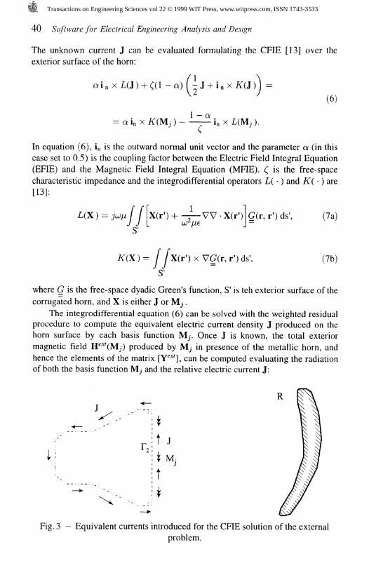
The integrodifferential equation (6) can be solved with the weighted residualprocedure to compute the equivalent electric current density J produced on thehorn surface by each basis function Mj. Once J is known, the total exteriormagnetic field H**'(Mj) produced by Mj in presence of the metallic horn, andhence the elements of the matrix [Y**'], can be computed evaluating the radiationof both the basis function Mj and the relative electric current J:
i t
|t J
i t
Fig. 3 - Equivalent currents introduced for the CFIE solution of the externalproblem.
Transactions on Engineering Sciences vol 22 © 1999 WIT Press, www.witpress.com, ISSN 1743-3533

Software for Electrical Engineering Analysis and Design 41
H"'(M;)= - - - K ( J ) . (8)
In the general case of horn radiating in presence of conducting objects, theabove procedure can be repeated. The equivalence theorem is again applied onthe perfectly conducting surface of the horn which is once again replaced by thesurface equivalent current J (Fig. 3). The CFIE can be again formulated on theextereior surface S' of the horn, however the operators L( - ) and K( • ) need to bemodified because the equivalent currents now radiates in presence of theconducting object R (Fig. 3). In the practical case of interest in which theconducting bodies nearby the horn are the reflectors of an antenna system, L( - )and K( - ) can be expressed as
In the above equations, V™ and K*™ account for free-space radiation andare given in equations (7), while V*®' and K**®' take care of contributions comingfrom field diffracted by the edges of the reflectors and can be evaluated by meansof the Uniform Theory of Diffraction (UTD) [10]. Geometric Opticscontributions L°° and K™ usually present in UTD formulations have beenneglected in this case because in practical reflector antenna systems the reflectorsshape and position are designed so as not to reflect signal back towards thefeeder.
Although feasible, the approach outlined above is very demanding from acomputational point of view. It is then more convenient resorting to aperturbative approach that can greatly reduce computational efforts maintainingacceptable accuracy.
The perturbative approach can be used because the presence of the reflectorsusually only slightly modifies the free-space radiation characteristic of the feeder.Denoting with J° the CFIE free-space solution, of equation (6), hereafterreferred to as non perturbed solution, equation (6) can be recast in the shorterform
where £° is the operator of the non perturbed problem (isolated horn). When thehorn radiates in presence of conducting objects (perturbed problem) the CFIE isrewritten as:
g + g, (11)
where C is the exact operator, sum of the non perturbed (£°) and difference (£')operators. Assuming that the solution J of the perturbed problem can beexpressed by adding a perturbative term J' to J°, with j' < J°, the CFIE (6) inpresence of reflectors becomes:
Transactions on Engineering Sciences vol 22 © 1999 WIT Press, www.witpress.com, ISSN 1743-3533

42 Software for Electrical Engineering Analysis and Design
(12)
Exploiting the linearity of the operators and disregarding the term £'(j' ),equation (12) can be simplified as:
fO(j') = g'_,C'(j\ (13)
where:
(I4a)
(14b)
(14c).
The solution of eqaution (13) gives the perturbation j' caused by the reflectorsthat can be used to compute the field HP'(Mj):
(15)
-
and subsequently the entries of the matrix [¥"'].
3 Numerical Results
The software package X_HORN [14] implements the technique outlined in theprevious section and has been used to compute the numerical results presented inthis section relative to a Dual Gregorian Rotatable Coverage satellite antenna at afrequency of 13 GHz.
The feeder of this antenna system is the V5A circular corrugated horn [8-9],whose copolar and cross polar radiation patterns (when considered as isolated)are shown in Fig. 4. These results show a very good agreement with availablemeasurements [8] and validates the approach for the case of free-space radiation(no interaction).
The radiation pattern of the isolated horn is also useful to assess the level ofinteractions between the horn and the two reflectors of the dual Gregoriansystem. From the geometry of the system (sketched in Fig. 5) and the radiationpattern of the isolated horn reported in Fig. 4, it is seen that the subreflector'sedges are strongly illuminated ( - 12dB with respect to the peak of radiation in
Transactions on Engineering Sciences vol 22 © 1999 WIT Press, www.witpress.com, ISSN 1743-3533

Software for Electrical Engineering Analysis and Design 43
90
Theta(degree)
180 Oam(dBi)
270
Fig.4 — Radiation pattern of the copolar (cp) and crosspolar (xp) fieldcomponents at (p - 45° for the VA5 horn.
the direction 0 = 0°), while the level of field radiated by the horn which directlyreaches the main reflector is well below -45dB with respect to the peak ofradiation. Consequently, the effect of direct interaction between the horn and themain reflector can be neglected without significantly degrading the accuracy ofthe technique.
Fig. 5 shows cross-polar radiation pattern of the horn when the horn isisolated and when the coupling between the V5A feeder and the subreflector ofthe Dual Gregorian antenna is taken into account. Only the crosspolar radiationpatterns are shown because they are more significant than the copolar patternsdue to their lower field levels. It is seen that when interaction between the feederand the subreflector is taken into account, the level of the crosspolar pattern inthe solid angle subtended by the main reflector rises up to 5 dB. In some satelliteantennas applications this increase can be critical and its detection in the earlystage of design can be very important to reduce development time.
The non-perturbed and perturbed magnetic and electric field amplitudedistributions over the horn opening are shown in Fig. 6. These results serve as ana posteriori validation of the perturbative approach since they show that thecorrective term is about 30dB lower than the non-perturbed field over most of thehorn aperture.
Transactions on Engineering Sciences vol 22 © 1999 WIT Press, www.witpress.com, ISSN 1743-3533

44 Software for Electrical Engineering Analysis and Design
. Non-perturbed Crosspolar
Perturbed Crosspolar
Fig. 5 — Comparison between the radiation pattern (dBi) of the cross-polar fieldcomponent for the isolated horn (non-perturbed) and the cross-polar fieldcomponent arising because of the interactions with the subreflector of the dualGregorian antenna (perturbed); y — 45°.
4 Conclusions
A software package for the analysis of circular corrugated horns radiating inpresence of nearby perfectly conducting structures has been presented. Thesoftware implements a hybrid method which combines several techniques (MM,CFIE and UTD), each suitable for the analysis of a particular region of theproblem space.
The computational cost of the problem is minimized by exploiting aperturbative approach to correct the solution relative to the isolated horn withcontributions due to the interactions with nearby conducting structures. Thisapproach is particularly convenient for the analysis of circular horns used asfeeder in reflector antenna systems where unwanted interactions are mainly dueto field diffracted by the reflector's edges and are responsible for increasing thecross-polarization level.
Transactions on Engineering Sciences vol 22 © 1999 WIT Press, www.witpress.com, ISSN 1743-3533

-40 -
-50 -
-60 -
-70 -
-80 -
-90 -
400-
-110 -
-120
Software for Electrical Engineering Analysis and Design 45
non perturbed
perturbation
H field
Fig. 6 - Comparison between amplitude (dB) distribution over horn aperture ofnon-perturbed field and field induced by diffraction (perturbation); elevation=0°,
azimuth= - 60°.
Acknowledgments
The authors wish to express their gratitude to Prof. Magdalena Salazar-Palma(Polytechnic University of Madrid, Madrid, Spain) and Dr. Rodolfo Ravanelli(Alenia Aerospazio, Rome, Italy) for invaluable suggestions and discussions.
This work was supported in part by Italian-Spanish Integrated Action (HI-1996 and HI-1997)
Transactions on Engineering Sciences vol 22 © 1999 WIT Press, www.witpress.com, ISSN 1743-3533

46 Software for Electrical Engineering Analysis and Design
References[1] AJ. Simons, A.F. Kay, "The scalar feed-a high performance feed for large
parabolic reflectors," IEE Conf. Pub. 27, 1966, pp. 213-217.[2] H.C. Minnett, MacA.B. Thomas, "A method of synthesizing radiation
patterns with axial symmetry," IEEE Trans. Antennas Propagat., Vol. AP-14, 1966, pp. 654-656.
[3] C.G. Parini, P.J.B. Clarricoats, A.D. Olver, "Cross-polar radiation fromopen-ended corrugated waveguides," Electron. Lett., 1975, no. 11, p. 567.
[4] A.D. Olver, P.J.B. Clarricoats, A.A. Kishk, L. Shafai, Microwave hornsand feeds, London and New York: IEE and IEEE Press, 1994.
[5] G.L. James, "Analysis and design of TEn to HEn corrugated cylindricalwaveguide mode converters," IEEE Trans. Microwave Theory Techn., Vol.MTT-29, 1981, pp. 1059-1066.
[6] E. Kuhn, V. Hombach, "Computer-aided analysis of corrugated horns withaxial or ring-loaded radial slots," Third International Conference onAntennas and Propagation ICAP 83, Norwich, UK, 12-15 April 1983.London, UK: IEE, 1983. pp. 127-131.
[7] J.M. Rieter, F. Arndt, "Efficient hybrid boundary contour mode-matchingtechnique for the accurate full-wave analysis of circular horn antennasincluding the outer wall geometry," IEEE Transactions on Antennas andPropagation, vol. 45, no. 3, pp. 568-570, Mar. 1997.
[8] R. Coccioli, G. Pelosi, R. Ravanelli, "Combined mode matching-integralequation technique for feeders optimization," in Software for ElectricalEngineering Analysis and Design. Editor P.P. Silvester, Southampton(UK): Computational Mechanics Publications, 1996.
[9] R. Coccioli, G. Pelosi, R. Ravanelli, "A mode matching-integral equationtechnique for the analysis and design of corrugated horns," AerospaceScience and Technology, vol. 2, no. 2, 1998.
[10] R.G. Kouyoumjian, P.H. Pathak, "A uniform geometrical theory ofdiffraction for an edge in a perfectly conducting surface," Proc. IEEE, Vol.62, 1974, pp. 1448-1461.
[11] R.F Harrington, J.R. Mautz, "Computational methods for transmissions ofwaves through apertures," in Electromagnetic scattering. Editor P.L.E.Uslenghi, New York: Academic Press, 1978.
[12] R.F. Harrington, J.R. Mautz, "A generalized network formulation foraperture problems," IEEE Trans. Antennas Propagat., Vol. AP-24,November 1976, pp. 870-873.
[13] P.L. Huddleston, L.N. Medgyesi-Mitschang, J.M. Putnam, "Combined fieldintegral equation formulation for scattering by dielectrically coatedconducting bodies," IEEE Trans. Antennas Propagat., Vol. AP-34, April1986, pp. 510-520.
[14] G.G. Gentili, G. Pelosi, R. Ravanelli, "Design and Optimization ofCorrugated Feeders: X_HORN Software Package," IEEE Mag. AntennasPropagat., Vol. 39, No. 5, October 1997, pp. 96-98.
Transactions on Engineering Sciences vol 22 © 1999 WIT Press, www.witpress.com, ISSN 1743-3533