software engineering ii
TRANSCRIPT
a
Table of Contents Chapter I Software Requirement Specification ......................................................................... 1
1 Introduction ........................................................................................................................ 1
1.1 Purpose ........................................................................................................................ 1
1.2 Scope ........................................................................................................................... 1
1.3 Intended audience & Reading Suggestion .................................................................. 2
1.4 Reference ..................................................................................................................... 2
2 Overall Description ............................................................................................................. 2
3 System Features .................................................................................................................. 4
4 External System Requirements ........................................................................................... 5
5 Other Non-Functional Requirements .................................................................................. 6
CHAPTER II – Project Plan .................................................................................................... 10
2 Introduction ........................................................................................................................... 10
2.3 Risk Assessment ............................................................................................................ 11
Project Milestones / Deliverables .................................................................................... 13
Work Breakdown Structure ............................................................................................. 14
Activities Log................................................................................................................... 15
Dependencies Table ......................................................................................................... 16
Gantt chart ........................................................................................................................ 17
Pert Chart ......................................................................................................................... 18
Chapter III Methodology ......................................................................................................... 19
Available Methodology ....................................................................................................... 19
Waterfall model ............................................................................................................... 19
Spiral methodology .......................................................................................................... 20
Prototyping ....................................................................................................................... 21
Incremental Model ........................................................................................................... 22
Rapid Application Development (RAD) Model .............................................................. 23
Chosen Methodology for Development ............................................................................... 24
CHAPTER IV Design Specification ........................................................................................ 26
4.1 Introduction: ................................................................................................................... 26
4.2 Purposes ......................................................................................................................... 26
4.3 Intended Audience and Reading Suggestion: ................................................................ 26
b
4.4 System Architectural Design ......................................................................................... 27
4.5 Class Diagram ................................................................................................................ 30
4.6 Use Case Diagram.......................................................................................................... 32
4.7 Activity Diagram ........................................................................................................... 38
4.8 State Transition Diagram ............................................................................................... 44
4.10 ER Diagram ................................................................................................................. 49
CHAPTER V – Testing Specifications .................................................................................... 52
5.1 Introduction .................................................................................................................... 52
5.2Purpose ............................................................................................................................ 52
Unit Test............................................................................................................................... 53
Component Test ................................................................................................................... 62
Validation Testing ................................................................................................................ 64
System Testing ..................................................................................................................... 66
SYSTEM EVALUATION ....................................................................................................... 69
Introduction .......................................................................................................................... 69
Evaluation Overview ........................................................................................................... 69
Evaluation of Project Deliverables ...................................................................................... 69
System Evaluation ............................................................................................................... 69
Criteria ................................................................................................................................. 69
PROJECT CONCLUSION ...................................................................................................... 70
Server Installation .................................................................................................................... 70
User Manual ............................................................................................................................. 74
Reference ................................................................................................................................. 75
Figure 1 Work Breakdown Structure ....................................................................................... 15
Figure 2: Figure showing Waterfall model .......................................................................... 19
Figure 3 Figure showing Spiral Model (Purcell, 2008) ....................................................... 20
Figure 4 Figure showing prototyping (istqbexamcertification) ......................................... 21
Figure 5 Incremental Model (istqbexamcertification) ........................................................ 22
Figure 6 RAD Figure (24point0) ........................................................................................... 23
Figure 7 Iterative Waterfall Diagram ....................................................................................... 24
Figure 8: MVC Architecture .................................................................................................... 27
Figure 9 MCV Architecture of Sasto Mart .............................................................................. 28
Figure 10: Client Server Architecture ...................................................................................... 29
Figure 11 Class Diagram ......................................................................................................... 31
Figure 12 Use case Diagram POS System Overall .................................................................. 32
c
Figure 13 Use Case Diagram for New Membership ................................................................ 33
Figure 14 Use Case Diagram MIS System .............................................................................. 35
Figure 15 Use Case Diagram for Sales Process ....................................................................... 36
Figure 16 Use Case Diagram for Authentication ..................................................................... 37
Figure 17 Activity Diagram POS Login .................................................................................. 38
Figure 18 Activity Diagram Issue Membership....................................................................... 39
Figure 19 Activity Diagram POS Overall ................................................................................ 40
Figure 20 Activity Diagram Sales............................................................................................ 41
Figure 21 Activity Diagram MIS Report ................................................................................. 42
Figure 22 Activity Diagram POS Top-Up ............................................................................... 43
Figure 23 State Transition Diagram Sasto Mart ...................................................................... 44
Figure 24Sequence Diagram Staff/Admin Login .................................................................... 45
Figure 25 Sequence Diagram Membership.............................................................................. 46
Figure 26 Sequence Diagram Top-Up ..................................................................................... 46
Figure 27 Sequence Diagram generate receipt ........................................................................ 47
Figure 28 Sequence Diagram Item Management..................................................................... 47
Figure 29 Sequence Diagram MIS ........................................................................................... 48
Figure 30 ER Diagram ............................................................................................................. 49
Table 3 Advantages & Disadvantages of Waterfall Model ................................................ 19
Table 4 Advantages & Disadvantage of Spiral Model ........................................................ 21
Table 5 Advantages & Disadvantage of Prototyping Model .............................................. 22
Table 6 Advantages & Disadvantage of Incremental Model ............................................. 23
Table 7 Advantages & Disadvantage of RAD Model ......................................................... 24

1
Chapter I Software Requirement Specification
1 Introduction
The information technology is revolutionizing the way we live and work. It is
changing all aspects of human life and lifestyle. This digital revolution has given mankind
the ability to treat information with mathematical precision, to transmit it at very high
accuracy and to manipulate it at will. The increasing demand for the new software is in
order to reduce the effort, time. Simple example while shopping customer spend several
minutes in order to get the payment bill. Normally this process includes the confirmation of
the goods selected, price calculation, deduct discount, add VAT, bill generation etc. in the
transnational ways. But using “Software as Solution”, this situation can be solved by using
the computerized system. In this types of computerized system the only goods identity no is
sufficient to generate the whole bills in a manner of seconds.
Similarly, this type of computerized system is a solution for SASTO MART a
recently opened department store in New Road, Kathmandu. This project is included as a
coursework in “Software Engineering II” in Islington College, Kathmandu, Nepal. This
project is related to the SASTO Mart for maintaining sales of commodities through POS
System with RFID cards.
1.1 Purpose
The purpose of this project is to develop a POS System and a separate MIS module
for the newly opened department store in the Kathmandu valley. It will provide the actual
information on the scope of this project, how we are developing the system etc.
In other word the purpose of this SRS document for Sasto Mart is to provide a
detailed overview of the new POS System, its parameters, goals. This document describes
the targeted audience, hardware and software requirements, user interface etc.
1.2 Scope
The Sasto Mart POS system is intended to work for the multiple counters in the Sasto
mart using the RFID technology. This project will result a new POS and separate MIS
web based module for the SASTO Mart having the following features:
In Scope
a. POS
b. RFID Card System
c. Separate MIS
d. Card with Barcode
e. Barcode Reader at each of the counter
Out Scope
a. Dot Matrix Printer
2
b. Computing Devices
1.3 Intended audience & Reading Suggestion
a. Intended Audience: The intended audience of the POS System are mentioned
below:
1) Senior Management
2) Owner
3) Staff or Employees
4) Customer
5) Sasto Mart Authorities
6) Billing Counter at the Sasto Mart
b. Reading Suggestion: The System includes the following reading suggestions.
1) Overall Description: It defines the general factors that affect the
product and its requirements. It doesn’t state the specific requirements
2) System Features: It specify overall features available in the system.
3) External Interface Requirements: It defines the hardware, software,
user as well as communication interface of the system.
4) Other Non-functional Requirements: It describes the non-functional
requirements like performance requirements, software quality
requirements, safety and security requirements etc.
1.4 Reference
IEEE. IEE Std 830-1998 IEEE Recommended Practise for Software Requirements
Specifications, IEEE Computer Society, 1998
ISO/IEC 18000-6: "Information technology - Radio frequency identification for item
management - Part 6: Parameters for air interface communications at 860 MHz to 960
MHz".
2 Overall Description a) Product Perspective
The Sasto Mart POS is the new system that will replace the traditional or manual
approach with the billing procedure. The system will work as point of sale or POS
application that will help the Sasto mart while keeping track of the sales and their
inventory. The customers selected items are scan by the help of the barcode scanner.
The System then calculates the price for the items including the VAT and also
deducting the discount. Likewise, after the calculation the system communicate with
the dot matrix bill printer in order to print the sales receipt.
b) Product Features
The Sasto Mart POS System will provide an interface to the staff by which they can
enter the information of the selected goods from the customer. This process is done
with the help of barcode scanner available in the counter. The system will also send

3
the information to the database as well as web based MIS module for the corporate
report.
1. The POS system should provide means to sell items to the counter staff
2. The POS system should provide a means for user authentication in to
the system through their respective username and password.
3. The POS system should provide a means of membership for the
regular customer with a top-up privilege card.
4. The POS system should provide a means to the counter staff to manage
the product (add, modify, delete, list etc.). And configure the POS
System with product category.
5. The POS system should provide a means to generate bills.
6. The system should provide a means to generate a MIS report based on
different category such as daily, monthly, counter wise sales report.
c) User Classes & Characteristics
1. Client Class (Counter Staff & Admin): POS client will be the
individual’s counter that is providing the billing services through the
Sasto mart. The POS system server inter-connect with the different
client counter where the client sync their transactional details with
the connect Sasto mart server in order to generate the report through
the MIS module.
2. Customer Class: They are temporary user class which normally
interact with the Sasto mart POS counter.
d) Operating Environment
1. The POS System must operate on the web-server.
2. The System must support the IE, Chrome, Firefox version 6.0 or
greater and Netscape Version 6.0 etc.
e) Design & Implementation Constraints
The POS system for the Sasto mart is initially limited with the windows based
computer and counter. The web server should be able to run PHP and maintain the
MySQL database.
1. All the HTML code must be HTML 4.0 Standard
2. The System must use the standard MySQL database
f) Assumptions, Constraints & Dependencies
1) AS-1. The Sasto Mart is open on the business day for day to day
department store business activities in which the staff or the employees
are expected to be on site.
2) AS-2. The Sasto Mart computing devices have multiple USB ports.
3) C-1. The POS system is currently limited to Windows operating
system no other operating system will be facilitated.
4) C-2. The POS system is limited to three customers at a time at a
specific counter.
4
5) DE-1. The proper operation of the POS system depends on the change
being made in the inventory to update the store.
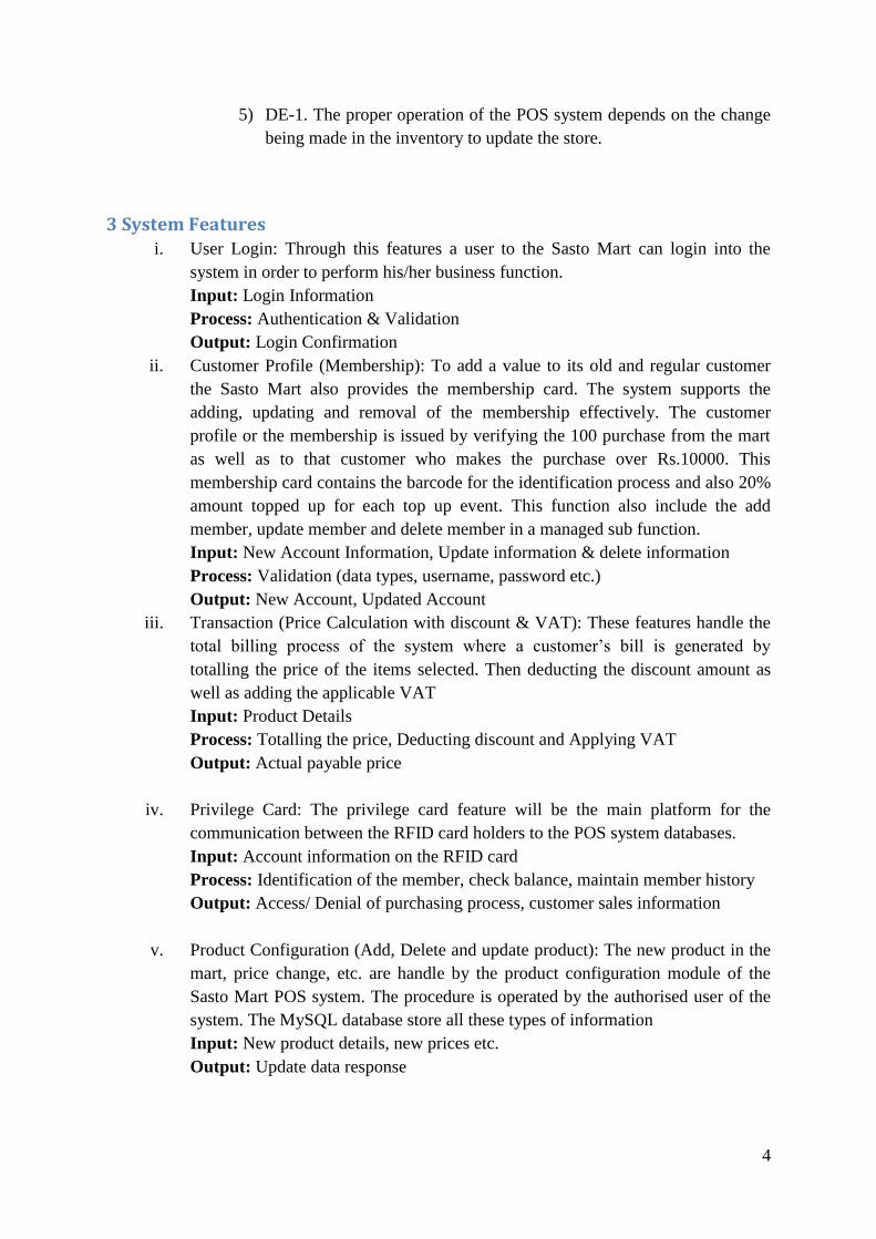
3 System Features i. User Login: Through this features a user to the Sasto Mart can login into the
system in order to perform his/her business function.
Input: Login Information
Process: Authentication & Validation
Output: Login Confirmation
ii. Customer Profile (Membership): To add a value to its old and regular customer
the Sasto Mart also provides the membership card. The system supports the
adding, updating and removal of the membership effectively. The customer
profile or the membership is issued by verifying the 100 purchase from the mart
as well as to that customer who makes the purchase over Rs.10000. This
membership card contains the barcode for the identification process and also 20%
amount topped up for each top up event. This function also include the add
member, update member and delete member in a managed sub function.
Input: New Account Information, Update information & delete information
Process: Validation (data types, username, password etc.)
Output: New Account, Updated Account
iii. Transaction (Price Calculation with discount & VAT): These features handle the
total billing process of the system where a customer’s bill is generated by
totalling the price of the items selected. Then deducting the discount amount as
well as adding the applicable VAT
Input: Product Details
Process: Totalling the price, Deducting discount and Applying VAT
Output: Actual payable price
iv. Privilege Card: The privilege card feature will be the main platform for the
communication between the RFID card holders to the POS system databases.
Input: Account information on the RFID card
Process: Identification of the member, check balance, maintain member history
Output: Access/ Denial of purchasing process, customer sales information
v. Product Configuration (Add, Delete and update product): The new product in the
mart, price change, etc. are handle by the product configuration module of the
Sasto Mart POS system. The procedure is operated by the authorised user of the
system. The MySQL database store all these types of information
Input: New product details, new prices etc.
Output: Update data response

5
vi. MIS: MIS Module of Sasto Mart is executed in order to produce the sales report
daily, monthly based on the total sales by the different counter of the Sasto mart.
Input: Individuals sales details by the counter including the member
Process: Manipulation of the different sales details
Output: Daily/Monthly Sales Report Generation, Counter-wise sales report and
customer-wise report generation.
vii. User Logout: At the end of the day the user can logout from the system.
4 External System Requirements External interface requirements state software, hardware or database elements with
which a system must interface. This part gives information to make sure that system will
communicate with the external components.
i. User Interfaces: .The platform through which the users of the POS system
inter-connect with each other. The user friendly GUI and the Web-Based
Interface is used for the system having the following features. And it supports
the entire latest browser like Chrome, Firefox, and IE etc.
1) The User Interface of POS system should specify the screen resolution.
2) The interface should be clean and easy to read & understand.
3) The interface should be intuitive for the user.
4) The interface should not include unsuitable language for the activity to
be performed.
5) The interface should provide the suitable feedback for the actions.
ii. Hardware Interfaces:
For the web based application the system hardware must inter-connect with
the system server through the internet with the help of LAN, WAN and
Ethernet cable.
1) The system is capable to interface with different hardware technologies
and it supports the active as well as passive RFID & barcode devices.
2) The hardware devices such as dot-matrix printer, barcode scanner etc
inter-connects with the computer via USB port.
iii. Software Interfaces:
Sasto Mart web application required the server like WAMP, XAMMP etc. in
order to communicate each other and also MySQL databases are required to
store the data during the operation. It describes the requirements for any
communication functions the product will use like e-mail, network
communication protocols, web browser and electronic forms. It also specifies
communication security data transfer rates, encryption issues and
synchronization mechanisms
1) The POS system communicates with the server to get the product
specification, promotions, discount etc.
iv. Communication Interfaces
6
The Sasto Mart POS system should use HTTP protocol in order to
communicate over the internet and TCP/IP protocol for the intranet
communication. It describes the requirements for any communication
functions the product will use like e-mail, network communication protocols,
web browser and electronic forms. It also specifies communication security
data transfer rates, encryption issues and synchronization mechanism
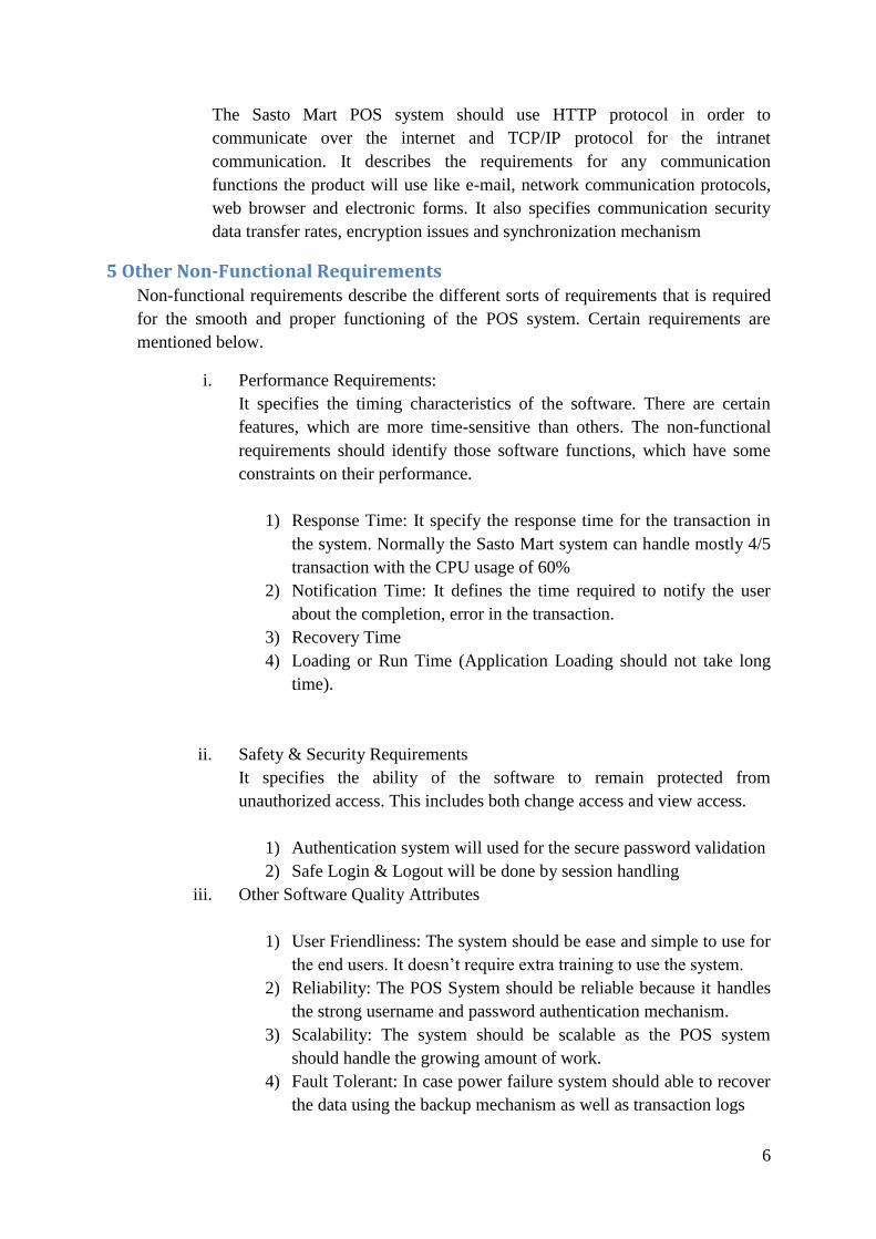
5 Other Non-Functional Requirements Non-functional requirements describe the different sorts of requirements that is required
for the smooth and proper functioning of the POS system. Certain requirements are
mentioned below.
i. Performance Requirements:
It specifies the timing characteristics of the software. There are certain
features, which are more time-sensitive than others. The non-functional
requirements should identify those software functions, which have some
constraints on their performance.
1) Response Time: It specify the response time for the transaction in
the system. Normally the Sasto Mart system can handle mostly 4/5
transaction with the CPU usage of 60%
2) Notification Time: It defines the time required to notify the user
about the completion, error in the transaction.
3) Recovery Time
4) Loading or Run Time (Application Loading should not take long
time).
ii. Safety & Security Requirements
It specifies the ability of the software to remain protected from
unauthorized access. This includes both change access and view access.
1) Authentication system will used for the secure password validation
2) Safe Login & Logout will be done by session handling
iii. Other Software Quality Attributes
1) User Friendliness: The system should be ease and simple to use for
the end users. It doesn’t require extra training to use the system.
2) Reliability: The POS System should be reliable because it handles
the strong username and password authentication mechanism.
3) Scalability: The system should be scalable as the POS system
should handle the growing amount of work.
4) Fault Tolerant: In case power failure system should able to recover
the data using the backup mechanism as well as transaction logs

7
5) Operating Platform: The POS system should operate of the
computer having the Microsoft Windows Xp and greater, with
minimum 1GHz processor and 256MB RAM.
6) Interface Metaphor: The POS system GUI must include the dialog
boxes, menus, buttons and also some screen instructions. And
minimize the use of pointer navigation then the keyboard
navigation.
7) Ease of Use: The POS system must be user friendly in terms with
ease menu, instructions etc.
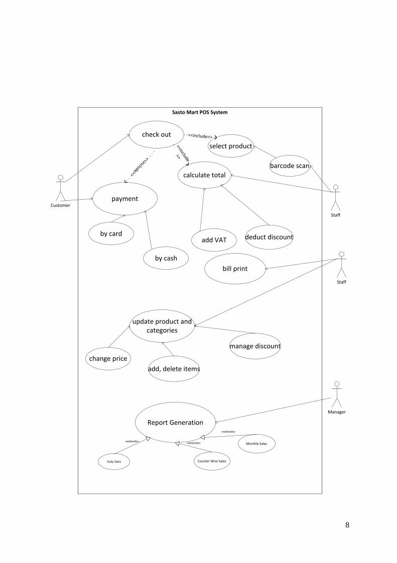
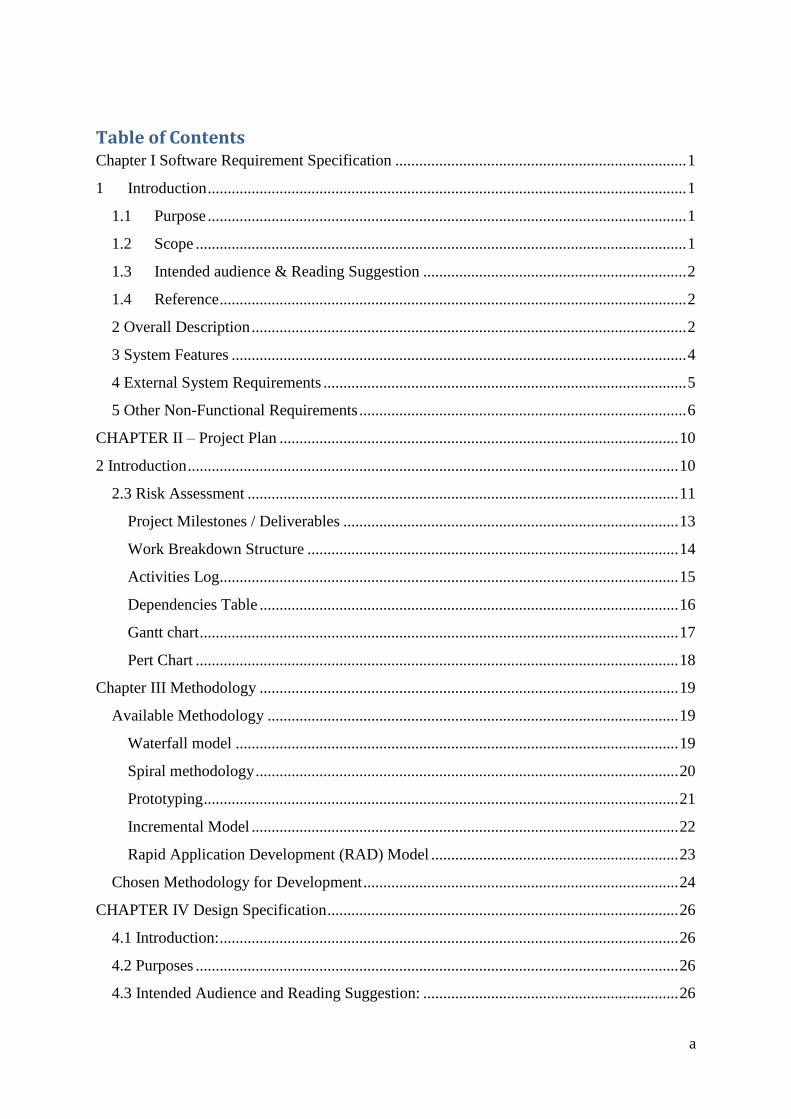
8
Customer
check out
Staff
select product
Staff
bill print
Report Generation
Daily Sales
Monthly Sales
Counter Wise Sales
«extends»
Sasto Mart POS System
Manager
payment
calculate total
<<include>>
<<include
>><<include>>
by card
by cash
add VAT deduct discount
«extends»
«extends»
barcode scan
update product andcategories
change price
add, delete items
manage discount
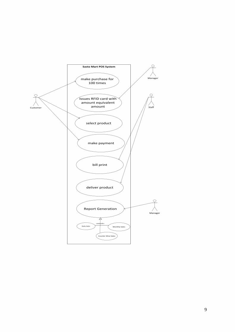
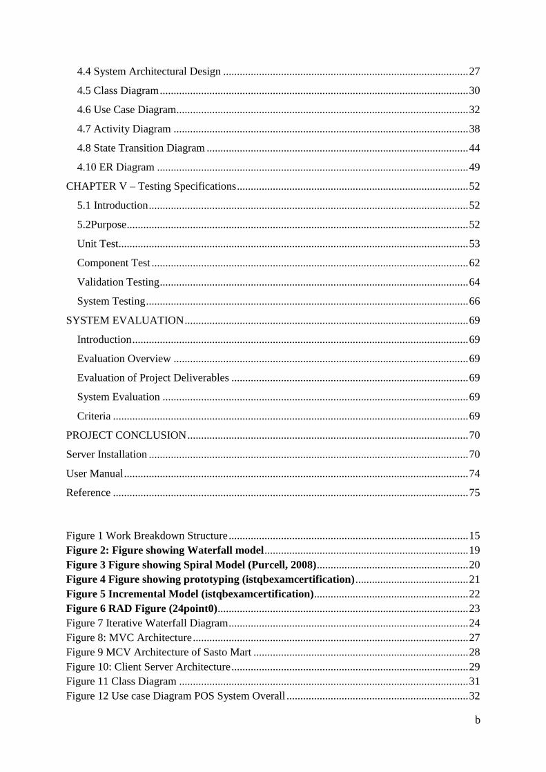
9
Customer
make purchase for100 times
Manager
Issues RFID card withamount equivalent
amount
select product
make payment
Staff
deliver product
bill print
Report Generation
Daily Sales Monthly Sales
Counter Wise Sales
«extends»
Sasto Mart POS System
Manager
10
CHAPTER II – Project Plan
2 Introduction
This document specific the overall approach applied to the planning phase of the
development cycle. These normally include the team members and the different task
allocated to the team members with response to the time frame provided by the project
manager.
2.1 Scope
The major scope of this system in to develop a web based point of sale software program for
a department store. This POS also include a separate MIS system in order to facilitate the
management part of the store.
2.2 Constraints
Normally constraints are the other important factors for the development cycle. The
following are the considerable constraints for the development of the Sasto Mart POS system.
2.2.1 COST
Cost reflects the competitive advantage of product and marginal utility & value to the clients.
In other word, it’s a pre estimation of the sum of the money required for the software
development. During the development of the POS all the direct as well as indirect cost should
be mentioned.

11
2.2.2 TIME
Time/Resource describes the structure of our group and its ability to fulfil commitments or
the ability to handle changes. For this POS system the project deadline is before 14th
January
2014. Likewise, the maximum human resource allocated was 5.
2.2.3 QUALITY
High quality for the system is maintained so to make the system more reliable and more
efficient. This constraint also can be affected by the total cost and time that is invested for the
completion of the project. So the constraint quality is proportional to the other two constraints
of the system i.e. Cost and the time.
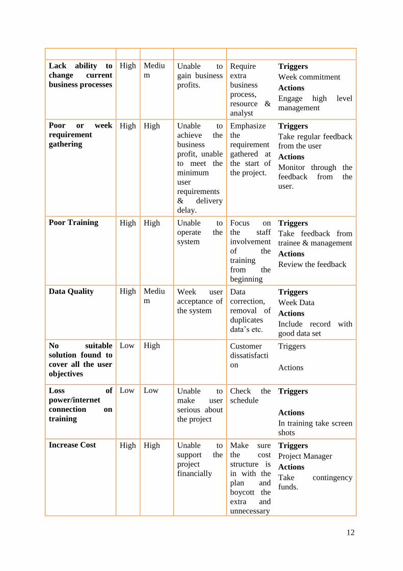
2.3 Risk Assessment
Risk
Project Size Overview
Time/Member Strategy
Project Schedule 6-7 weeks Create Project plan
Team Size 5 members Divide work to group,
assigned project manager,
create communication plan &
meetings
Risk Pro
babi
lity
Impact Effect on
project
Reduction
Strategy
Trigger & Action
Loss to project
key staff.
Low High Unable to
complete
project
Focus on
the
important of
the project
within the
group
members
Triggers:
Reports of absence, or
diversion of staff to
other work
Actions:
Find alternative
resources in case of
unexpected absence;
ensure complete
records of work are
available at any point.
Change in
requirements
Low High Time-quality-
cost
Make sure
the
requirement
is fully
identified
and verified
before the
project
developmen
t process.
Triggers
Ask for changes to
agree the specification
Actions
Discuss impact of
change on schedules
& implement project
change, if agreed.
12
Lack ability to
change current
business processes
High Mediu
m Unable to
gain business
profits.
Require
extra
business
process,
resource &
analyst
Triggers
Week commitment
Actions
Engage high level
management
Poor or week
requirement
gathering
High High Unable to
achieve the
business
profit, unable
to meet the
minimum
user
requirements
& delivery
delay.
Emphasize
the
requirement
gathered at
the start of
the project.
Triggers
Take regular feedback
from the user
Actions
Monitor through the
feedback from the
user.
Poor Training High High Unable to
operate the
system
Focus on
the staff
involvement
of the
training
from the
beginning
Triggers
Take feedback from
trainee & management
Actions
Review the feedback
Data Quality High Mediu
m Week user
acceptance of
the system
Data
correction,
removal of
duplicates
data’s etc.
Triggers
Week Data
Actions
Include record with
good data set
No suitable
solution found to
cover all the user
objectives
Low High Customer
dissatisfacti
on
Triggers
Actions
Loss of
power/internet
connection on
training
Low Low Unable to
make user
serious about
the project
Check the
schedule Triggers
Actions
In training take screen
shots
Increase Cost High High Unable to
support the
project
financially
Make sure
the cost
structure is
in with the
plan and
boycott the
extra and
unnecessary
Triggers
Project Manager
Actions
Take contingency
funds.

13
cost.
Poor
communications
High Low. Week
cohesion.
Monitor the
project
progress
regularly
Triggers
PM unaware about the
project progress
Actions
Make sure that the
staffs notify every
progress to the project
manager.
The work is divided into the following content areas:
a. Project management: Anit Thapaliya, Manoj Rana
b. Requirements: Karun Lama, Rachana Shrestha, Roshan Rai, Manoj Rana & Anit
c. Development: Anit Thapaliya, Manoj Rana & Roshan
d. Architecture: All Members
e. Test: Roshan, Anit, Manoj, Rachana & Karun
Name Role Phone Email
Anit Thapaliya Project Manager 9849054113 [email protected]
Manoj Rana Analyst [email protected]
Karun/Rachana Designer
Anit/Manoj Programmer
Roshan Rai Tester
Project Milestones / Deliverables
Milestone Estimated Completion Date Member
Project Plan 14th
Nov 2013 Anit Thapaliya
Requirement
Specification
21th
Nov 2013 Anit Thapaliya
Design Specification 30th
Nov 2013 Manoj Rana
Source Code 15th
Dec 2013 Anit Thapaliya & Manoj
Rana
Test Result 22th
Dec 2013 Rachana Shrestha & Roshan
Rai
User Manual 19th
Dec 2013 Karun Lama
Installation Plan 21th
Dec 2013 Rachana Shrestha

14
Work Breakdown Structure
Work Member Milestone Dependencies
1. Planning Anit
1.1 Create scope of user
requirements
1.2 Project team selection
1.3 Development of project
plan
1.4 Milestone (Plan
Approval)
1.3
2. Analysis Anit/Manoj SRS 1.3
2.1 Requirement Analysis
2.2 List Functional
Requirement
2.1
2.3 List Non-Functional
Requirement
2.1
2.4 Prepare SRS 2.1
3. Design Anit/Manoj/Rachana SDS 2.4 (SRS)
3.1 Data Design
3.2 Interface Design
3.2.1 User Interface/ Front
End
3.2.2 SQL Database/ Back
End
3.3 Component Design
3.4 Behavioural Design
3.5 Architecture Design
4. Development ALL Executable OS 3 (SDS)
4.1 POS Development
4.2 MIS Development
5. Testing Rachana/Roshan Test Log 4 (Executable
OS)
5.1 Test Case Planning
5.2 Conduct Testing 5.1
6. Deployment Karun/Roshan 5 ( Tested and
Debugged
executable OS)
6.1 Develop installation
Plan
6.2 Develop user manual
6.3 Installation 6.1
6.4 User Training

15
Figure 1 Work Breakdown Structure
Activities Log
Task Days Start date End date Dependency Milestones
1.0 Project Planning 4 10/11/13
14/11/13
1.1 Prepare Project
Plan
4 10/11/13
14/11/13 Project Plan
2.0 Analysis 6 15/11/13
21/11/13 1.0
2.1 Requirement
Analysis
3 15/11/13
18/11/13 1.1
2.2 Prepare SRS
document
3 18/11/13
21/11/13 2.1 SRS document
3.0 Design 8 22/11/13
30/11/13 2.0
3.1 Data design 2 22/11/13
24/12/13
3.2 Architectural design 2 24/11/13
26/11/13
3.3 Design Specification
Preparation
4 26/11/13
30/11/13 3.1, 3.2 Design
Specification
4.0 Development 12 03/12/13
15/12/13 3.0
4.1POS Development 6 03/12/13
09/12/13 Source for
POS
4.2 MIS Development 6 10/12/13
16/12/13 Source for MIS

16
5.0 Testing 6 16/12/13
22/12/13 4.0
5.1 Test Plan
Preparation
3 16/12/13
19/12/13 Test Plan
5.2 Test Data 3 19/12/13
22/12/13 5.1 Test Result
6.0 Deployment 7 18/12/13
25/12/13 5.0
6.1 User Manual
Development
1 18/12/13
19/12/13 User Manuals
6.2 Installation Plan 2 19/12/13
21/12/13 Installation
Plan
6.3 System Installation 2 21/12/13
23/12/13 6.2
6.4 User Training 2 23/12/13
25/12/13
7.0 Review 2 25/12/13
27/12/13
Dependencies Table
Task
no
Task name Duration Dependencies Milestone
T1 Background Study
2
T2 Requirement Gathering 3 T1
T3 Prioritizing requirements 1 T2
T4 Prepare SRS 3 T3 M1
T5 Data Design 2 M1
T6 Architectural Design 2 T5
T7 Prepare SDS 4 T5,T6 M2
T8 Develop POS module 6 M2
T9 Develop MIS module 6 M2
T10 Testing (Black Box) 1 M3
T11 Testing (White Box) 2 M3
T12 Test Log Preparation 2 T13,T14 M3
T13 User Manual Preparation 1 M3 M4
T14 Installation 2 M4
T15 Training 2 T15
17
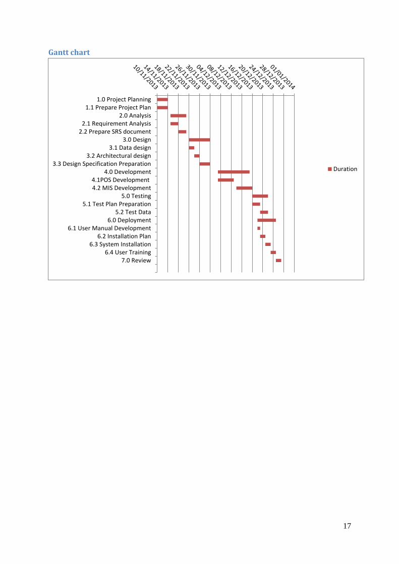
Gantt chart
1.0 Project Planning1.1 Prepare Project Plan
2.0 Analysis2.1 Requirement Analysis
2.2 Prepare SRS document3.0 Design
3.1 Data design3.2 Architectural design
3.3 Design Specification Preparation4.0 Development
4.1POS Development4.2 MIS Development
5.0 Testing5.1 Test Plan Preparation
5.2 Test Data6.0 Deployment
6.1 User Manual Development6.2 Installation Plan
6.3 System Installation6.4 User Training
7.0 Review
Duration
18
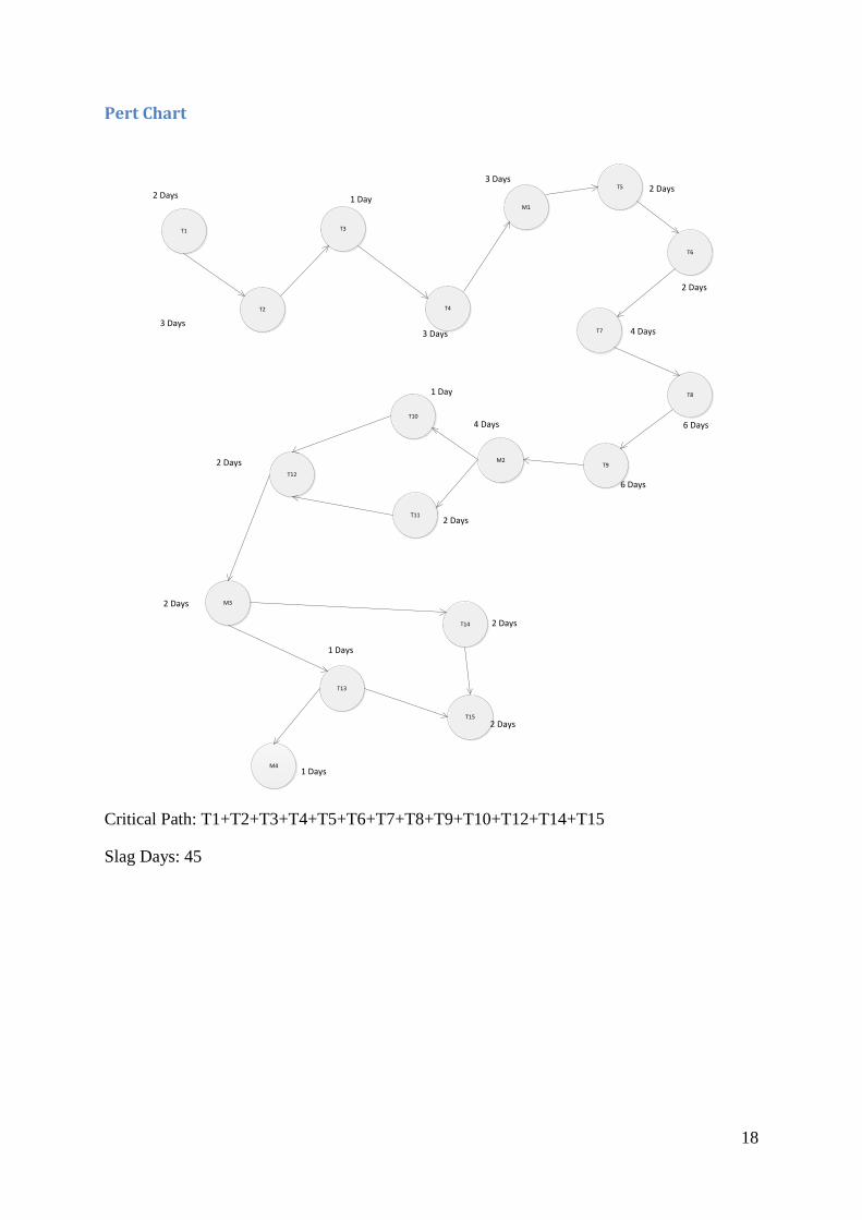
Pert Chart
T1
T2
T3
T4
M1
T5
T6
T7
T8
T9M2
T10
T11
T12
M3
T13
T14
T15
M4
2 Days
3 Days
1 Day
3 Days
2 Days
2 Days
4 Days
6 Days
6 Days
1 Day
2 Days
2 Days
1 Days
2 Days
2 Days
3 Days
4 Days
2 Days
1 Days
Critical Path: T1+T2+T3+T4+T5+T6+T7+T8+T9+T10+T12+T14+T15
Slag Days: 45

19
Chapter III Methodology
Available Methodology
There are various types of software development methodologies.
Waterfall model
The waterfall model is a sequential software development model. In other word it is
defined as a process for the creation of software in which development is seen as flowing
steadily downwards like a waterfall in the nature. The origin of the term “waterfall” is
cited to be an article by Winston W. Royce. (Rouse, 2007). The unmodified waterfall
model progress flows from top to the bottom just like a normal waterfall.
The model starts with requirements specification, when the requirement are fully
complete then proceeds to design. This section of design must be the plan for the
implementation of that design by the programmers. Likewise after the implementation
and integration the testing phase is carried out. The error introducted in the earlier pahse
are carried out in the testing phase. Finally the software system is installed and later
maintained to introduce the modification (Sky, 2007).
Figure 2: Figure showing Waterfall model
Advantage Disadvantage
Very easy to implement (Linear) Only able to use when requirement are fixed
Required minimum resource Unable to move back to the previous stage
Documentation is produced at every stages If mistake happen on middle, should start
from the scratch
Testing is done to check code is running
correct or not
Tester role only happen in the test phase
Table 1 Advantages & Disadvantages of Waterfall Model

20
Spiral methodology
The spiral model, also known as the spiral lifecycle model, is a systems development
lifecycle (SDLC) model used in information technology. This model of development
combines the features of the prototyping model and the waterfall model. The spiral model is
favoured for large, expensive, and complicated projects. The Spiral Model is an evolutionary
software process model that couples the iterative nature of prototyping with the controlled
and systematic aspects of the Linear Sequential Model.
In response to the weakness and failure of the waterfall model many new models were
developed that add some form of iteration to the software development process. In spiral
model, the development team starts with a tiny set of requirements and goes through each
development phase (excluding the installation and maintenance phase) for those set of
requirements. Based on the lesson learned through risk analysis process, the development
team adds functionality for additional requirements in every increasing spiral until system
gets ready for installation (Purcell, 2008). Each iteration is prior to the production of version
is a prototype of the application. Hence, it is more recommended to use spiral model when
the cost and risk evaluation is important and the project is complex (better for high risk
project).
Figure 3 Figure showing Spiral Model (Purcell, 2008)
21
Advantage Disadvantage
Avoidance of risk is enhanced Can be a costly model to use
Good for large and critical projects Risk analysis require highly expertise
personal
Strong approval & document control Project success is dependent on the risk
analysis phase
Additional function can be added at the end Not feasible for small projects
Table 2 Advantages & Disadvantage of Spiral Model
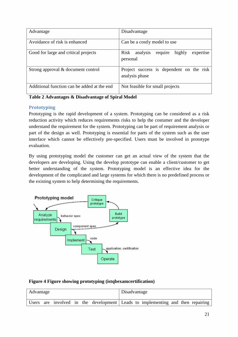
Prototyping
Prototyping is the rapid development of a system. Prototyping can be considered as a risk
reduction activity which reduces requirements risks to help the costumer and the developer
understand the requirement for the system. Prototyping can be part of requirement analysis or
part of the design as well. Prototyping is essential for parts of the system such as the user
interface which cannot be effectively pre-specified. Users must be involved in prototype
evaluation.
By using prototyping model the customer can get an actual view of the system that the
developers are developing. Using the develop prototype can enable a client/customer to get
better understanding of the system. Prototyping model is an effective idea for the
development of the complicated and large systems for which there is no predefined process or
the existing system to help determining the requirements.
Figure 4 Figure showing prototyping (istqbexamcertification)
Advantage Disadvantage
Users are involved in the development Leads to implementing and then repairing
22
process way of development
Errors can be detected initially Incomplete application may cause application
not to be used as the full system
Missing functionalities can be identified
easily
Lack adequate problems analysis
Table 3 Advantages & Disadvantage of Prototyping Model
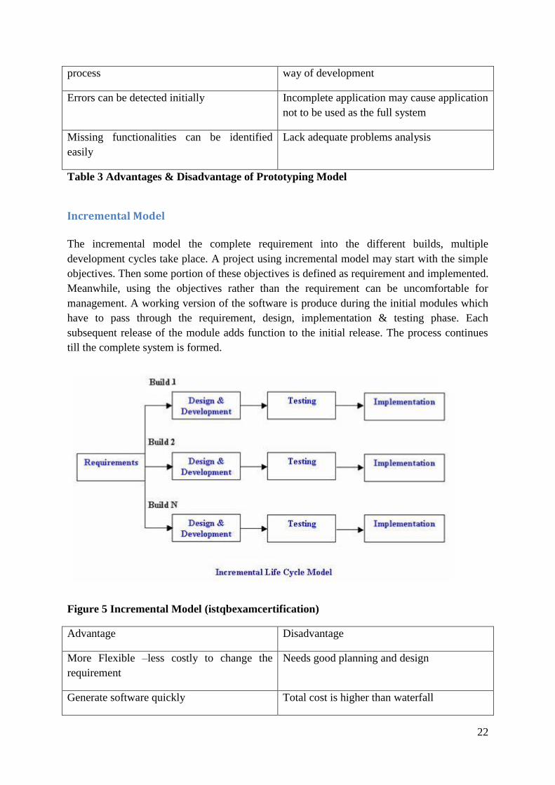
Incremental Model
The incremental model the complete requirement into the different builds, multiple
development cycles take place. A project using incremental model may start with the simple
objectives. Then some portion of these objectives is defined as requirement and implemented.
Meanwhile, using the objectives rather than the requirement can be uncomfortable for
management. A working version of the software is produce during the initial modules which
have to pass through the requirement, design, implementation & testing phase. Each
subsequent release of the module adds function to the initial release. The process continues
till the complete system is formed.
Figure 5 Incremental Model (istqbexamcertification)
Advantage Disadvantage
More Flexible –less costly to change the
requirement
Needs good planning and design
Generate software quickly Total cost is higher than waterfall

23
Easy to test and debug Needs a clear definition of the system
Easy to manage risk Requirement must be clear and well defined
Table 4 Advantages & Disadvantage of Incremental Model
Rapid Application Development (RAD) Model
Rapid model is rapid application development. It is also called as a type of the incremental
model. In RAD, functions are developed in parallel. The development processes are bound
with the time boxed, delivered and then assembled into a running prototype. This can be very
useful to deliver the project progress to the customer for feedback regarding their
requirements.
Figure 6 RAD Figure (24point0)
24
Advantage Disadvantage
Reduce development time Needs highly skilled manpower
Increase reusability of components Modularized system can only be built using
RAD
Increase client feedback High dependency on modelling skills
Table 5 Advantages & Disadvantage of RAD Model
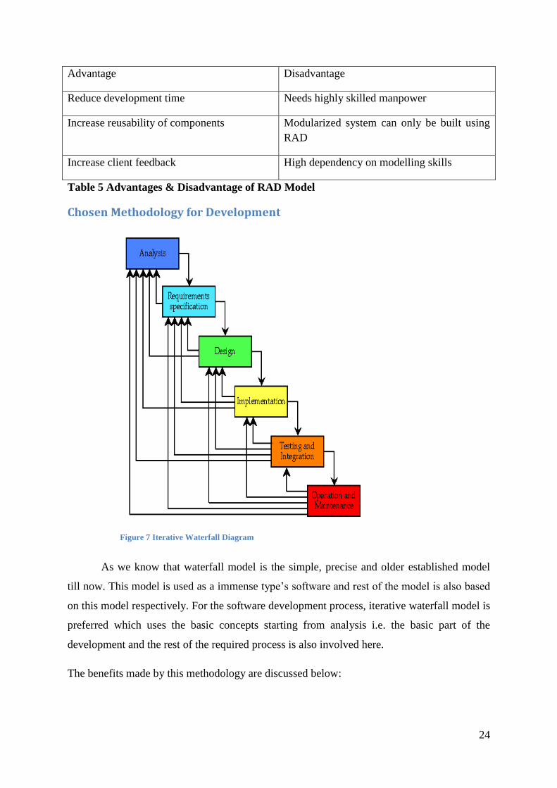
Chosen Methodology for Development
As we know that waterfall model is the simple, precise and older established model
till now. This model is used as a immense type’s software and rest of the model is also based
on this model respectively. For the software development process, iterative waterfall model is
preferred which uses the basic concepts starting from analysis i.e. the basic part of the
development and the rest of the required process is also involved here.
The benefits made by this methodology are discussed below:
Figure 7 Iterative Waterfall Diagram

25
1. Analysis: Sufficient problem understanding to write a requirements specification
document.
2. Specification: The required specification that unequivocally communicates the required
quality of the system to the designer.
3. Design: A design document that decidedly communicates the design to the implementers.
4. Implementation: The script code and documentation, prepared to be tested.
5. Testing and Integration: The tested code in operational state.
6. Maintenance: Changes in requirements may require additional performance and testing
or additional design work, or even a new analysis.
26
CHAPTER IV Design Specification
4.1 Introduction:
The objectives of this section of the system specification are to model the proposed system.
The lists of requirements that are gathered in previous chapter are to be design in this chapter.
This section contains different UML diagrams to design the requirements UML stands for
Unified modelling language that is used in OOAD approaches in Software Company. UML is
treated as a rich language that is used to model any business functions, structures.
4.2 Purposes The main purpose of design specification document is as follows:
i) Design specification document is used for various functions from laying out plans for
a new space ship to addressing the design concerns of the system.
ii) Provide the hawk eye structure of the project through different pictorial
representation.
iii) The expectations of user are documented, and are agreed by the users and developer
team.
iv) It involves the thorough data, functional requirements and behavioral requirements.
v) It clears the way to the programmers giving the plan and guidelines on how the
software necessity ought to be actualized.
vi) The design document additionally ensures that the present design sums up all the
explicit necessities of the arrangement ideal and additionally the inherent necessities
anticipated by the customer.
4.3 Intended Audience and Reading Suggestion:
The intended audience for this document is most likely the project owner and somehow we
can integrate users of the system also.
4.3.1 Project Owner: For any academic project the project owner simply justly the
involvement of the academic institutions that’s why Islington College virtually stay as the
project owner of this project
4.3.2 Programmer: Programmer refers the students who is undertaking the project and
responsible for all the sort s of development process in software engineering.
4.3.3 User: The user will be implementing and bringing the system in use. The User Interface
(UI) will be shared among the different users.
27
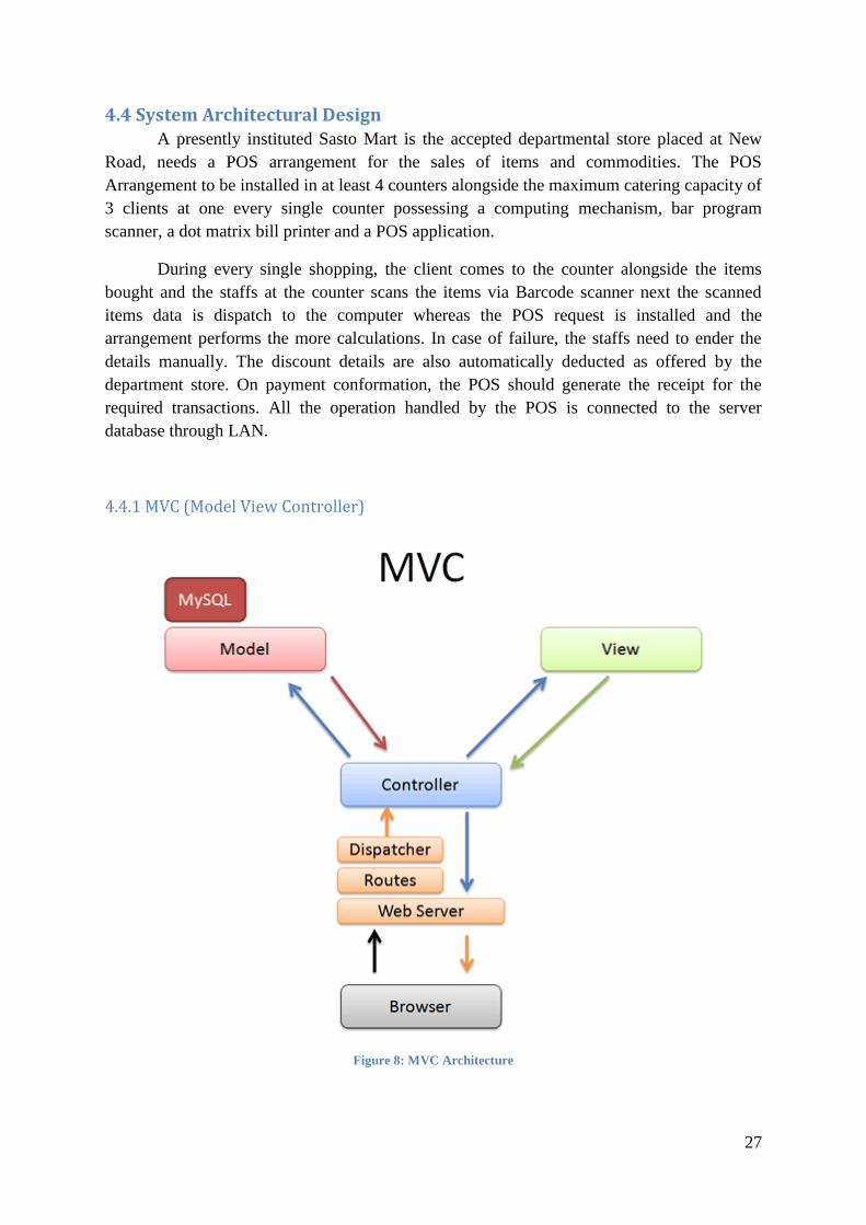
4.4 System Architectural Design A presently instituted Sasto Mart is the accepted departmental store placed at New
Road, needs a POS arrangement for the sales of items and commodities. The POS
Arrangement to be installed in at least 4 counters alongside the maximum catering capacity of
3 clients at one every single counter possessing a computing mechanism, bar program
scanner, a dot matrix bill printer and a POS application.
During every single shopping, the client comes to the counter alongside the items
bought and the staffs at the counter scans the items via Barcode scanner next the scanned
items data is dispatch to the computer whereas the POS request is installed and the
arrangement performs the more calculations. In case of failure, the staffs need to ender the
details manually. The discount details are also automatically deducted as offered by the
department store. On payment conformation, the POS should generate the receipt for the
required transactions. All the operation handled by the POS is connected to the server
database through LAN.
4.4.1 MVC (Model View Controller)
Figure 8: MVC Architecture

28
Model–view–controller (MVC) is a software outline for implementing the user
interfaces. It divides the software into three interconnected portions to distinct inner
representations of data from the methods that data gave to or consented from the user
4.4.1.1 A model notifies its associated sights and controllers after there has been a change in
its state. This notification permits the sights to produce notified output, and the controllers
to change the obtainable set of commands. A passive implementation of MVC omits these
notifications, because the request does not need them or the software period does not
support them.
4.4.1.2 A view requests information from the model that it needs for obtaining an output
representation to the user.
4.4.1.3 A controller can launch commands to the model to update the model's state. It can
also send commands to its associated view to change the view's presentation of the model.
ModulesAuthentication
AdminCounter Staff
Database connection
ViewLogin UI
Report UIAddcustomer UI
Home UI
ControllerLogin controller
database controllerSession controller
Member
Data Query
Data
Request
Request
Request
Response
Database
Figure 9 MCV Architecture of Sasto Mart

29
4.4.2 Client Server Architecture
Figure 10: Client Server Architecture
Client server architecture partially divides the complete system into three different aspects
which include the database server, a main server as well as a client system. In this Sasto mart
system the four different POS terminal would react as the client system, a database server
system will be available for the storage during the business procedure. Likewise a main
server will be available for interpreting the database into the client terminal.
30
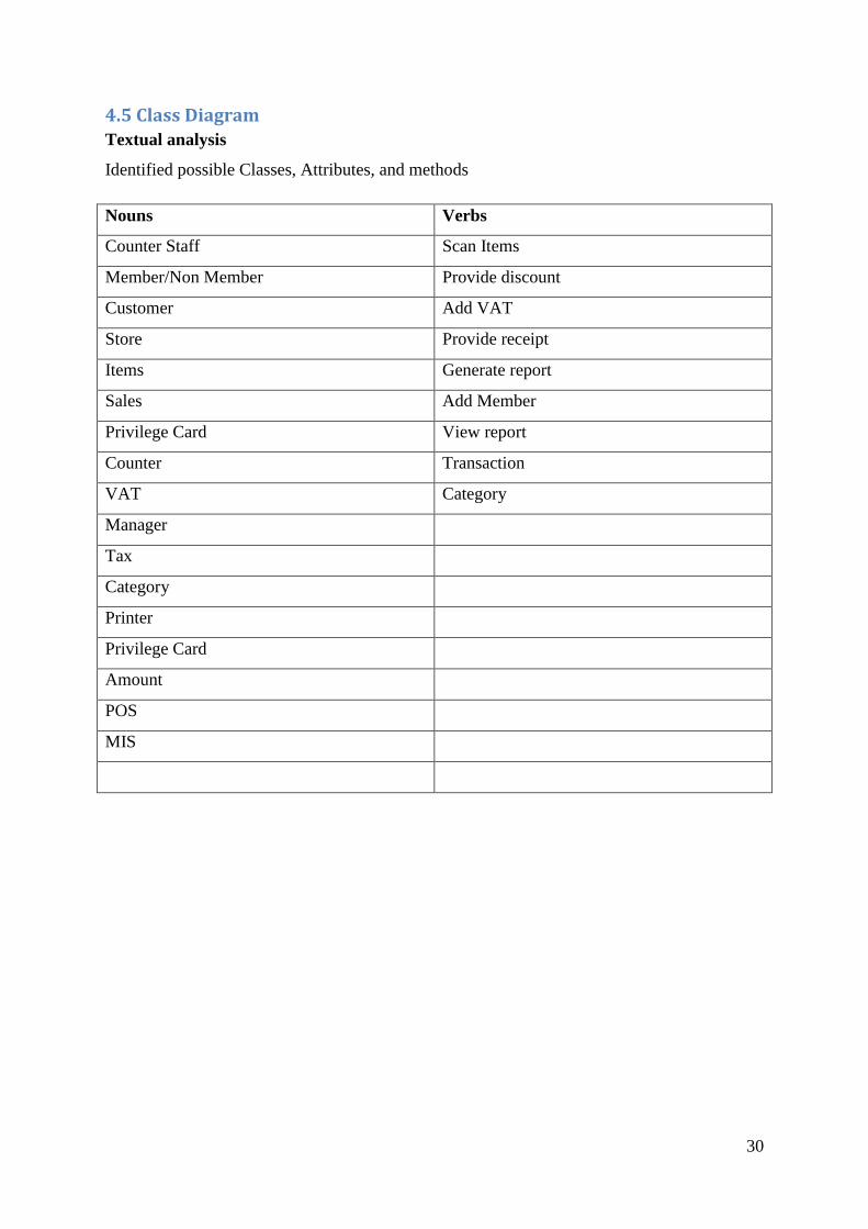
4.5 Class Diagram
Textual analysis
Identified possible Classes, Attributes, and methods
Nouns Verbs
Counter Staff Scan Items
Member/Non Member Provide discount
Customer Add VAT
Store Provide receipt
Items Generate report
Sales Add Member
Privilege Card View report
Counter Transaction
VAT Category
Manager
Tax
Category
Printer
Privilege Card
Amount
POS
MIS

31
-staff_id-counter_id-contact-staff_name-purchase_order
Employee
-item_id-item_name-quantity-price-counter_id-bill
Item
+purchaseItem()
-customer_id-balance-name-
Customer
+calculateAmt()
-transaction_id-customer_id-iterm_id-staff_id-payment
Transaction
-bill_id-customer_id-item_id-vat-total amount
Bill
-counter_id--
Counter
-item_id-category_id
Item_category
+takeOrder()
-counter_id-
staff
+viewReport()
-id
Manager
1
*
0..**
1 1
1
1
1
1
1
*
+topupamount()()
-card_no-balance
Privilege Card
11
1 0..*
+make purchaser()
-name-no of purchase
Non Member
+make purchase()
-RFID_no-Name
Member
+make decision()
-report_date-type
Report
0..1
1..*
1
1
0..1
1
Figure 11 Class Diagram

32
4.6 Use Case Diagram
Employee
Admin
Staff
Customer
Process Sales
POS System
Login
Payment
generate receipt
calcute totals
add vatdeduct discount
«extends» «extends»
generate salesreport
view sales reports
Received receipt
Figure 12 Use case Diagram POS System Overall
Use case name POS System Overall
Actors Staff, Customer & Admin
Use case Login
Process Sales
Calculate totals
Payment
Generate receipt
Generate sales report
Description Initially, a customer appears to the Sasto mart and makes the
selection of the product in order to make purchase. The counter
staff processes the sales through the POS terminal available in the

33
counter with the selected items details. Then the counter staffs
calculate the total including the VAT and deducting the discount
based on the offer provided to the customer. Finally the customer
makes the payment and the counter staffs generate the receipt for
the customer. Meanwhile the manager can generate the overall
sales report based on the daily, monthly, counter wise sales from
the Sasto mart.
POS system New Membership Use Case
staff
customer
ask for membership
check customerdetails
verify customerdetails
provide prelivedgecard
ask for membershipcancelation
check remainingamount/ balance
refundbalanceamount
terminatemembershi
p
customertransaction
«extends»
Member
Figure 13 Use Case Diagram for New Membership
34
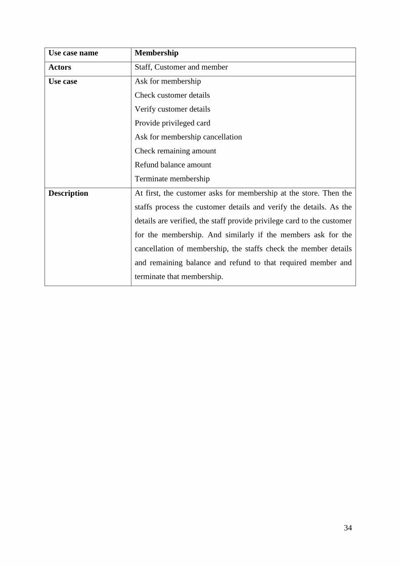
Use case name Membership
Actors Staff, Customer and member
Use case Ask for membership
Check customer details
Verify customer details
Provide privileged card
Ask for membership cancellation
Check remaining amount
Refund balance amount
Terminate membership
Description At first, the customer asks for membership at the store. Then the
staffs process the customer details and verify the details. As the
details are verified, the staff provide privilege card to the customer
for the membership. And similarly if the members ask for the
cancellation of membership, the staffs check the member details
and remaining balance and refund to that required member and
terminate that membership.
35
MIS
login
gather sales data
generate salesreport
view overallsales
reports
Daily Sales Report Monthly SalesReport
Counterwise SalesReport
«extends»«extends»
«extends»
Staff Admin
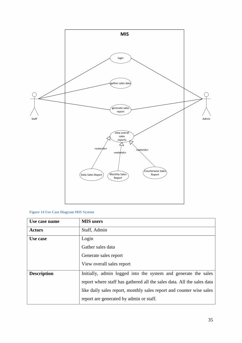
Figure 14 Use Case Diagram MIS System
Use case name MIS users
Actors Staff, Admin
Use case Login
Gather sales data
Generate sales report
View overall sales report
Description Initially, admin logged into the system and generate the sales
report where staff has gathered all the sales data. All the sales data
like daily sales report, monthly sales report and counter wise sales
report are generated by admin or staff.

36
POS Sales
select itmes
scan items
calculate total
add VAT deduct discount
payment
staff customer
by cash by card
deduct frommembership card
generate receipt
«extends»«extends»
«extends» «extends»
Figure 15 Use Case Diagram for Sales Process
Use case name Sales report
Actors Staff, Customer
Use case Select items
Scan items
Calculate total
Payment
Deduct from membership card

37
Generate receipt
Description At first, the customer selects the items from the mart and then the
staffs at the counter scans the following items to check the amount
of the items and check whether the items get discount or to add
vat. The customer then does the payment either by cash or by card.
The staffs then take the payment and deduct the amount and
generate receipt.
POS Authentication
Login
username password
logout
«extends» «extends»
StaffAdmin
Figure 16 Use Case Diagram for Authentication
Use case name Authentication
Actors Staff, Admin
Use case Login
Logout
Description Initially, the POS system authentication is required in order to
recognize the type of the user by the system. Where the admin as
well as the counter staff identify their details to the system in order
to perform the business function.
38
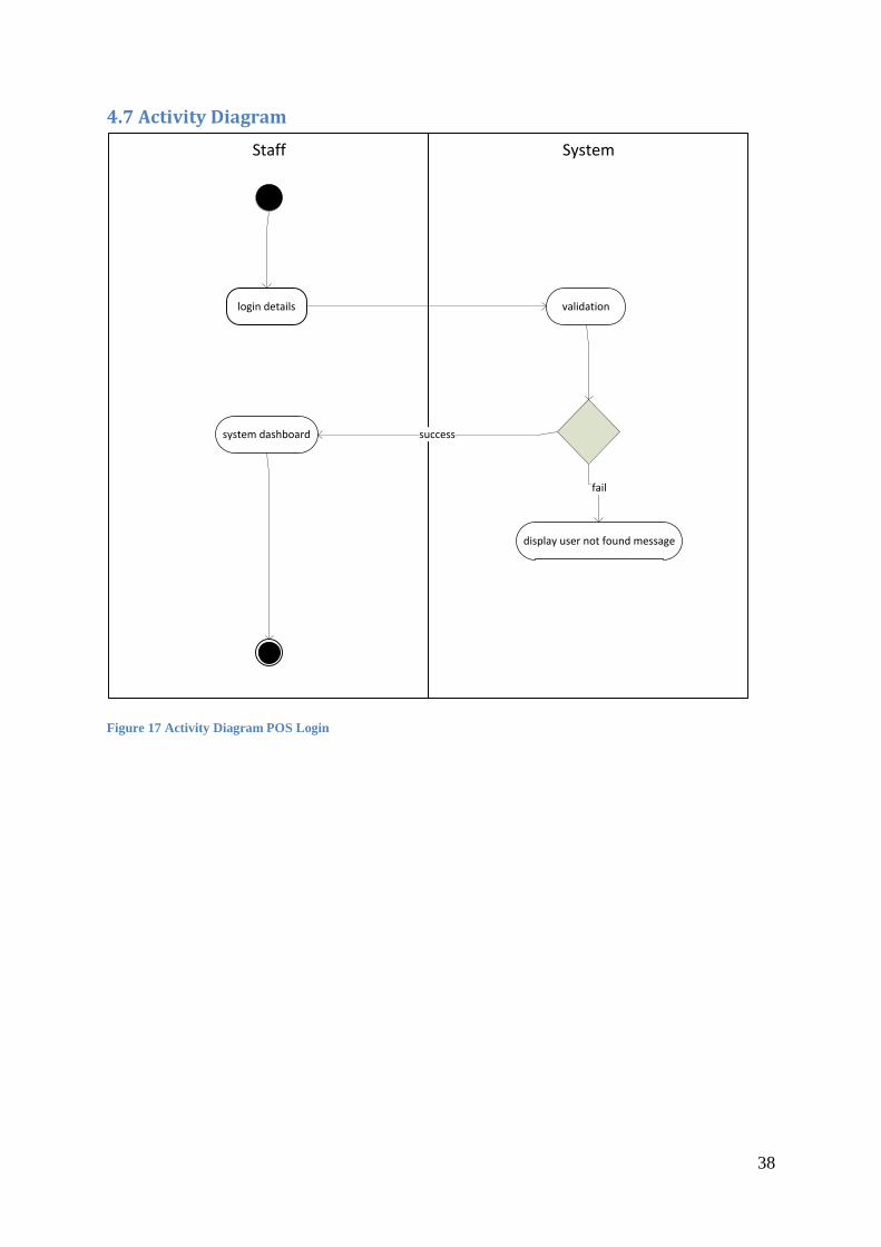
4.7 Activity Diagram
SystemStaff
login details validation
system dashboard
display user not found message
fail
success
Figure 17 Activity Diagram POS Login

39
Systemstaff
enter customer details
retrieve total no of purchase & amount
if total no of purchase > 100 or sales amount >10000
Provide membership/card
Yes
no
Figure 18 Activity Diagram Issue Membership
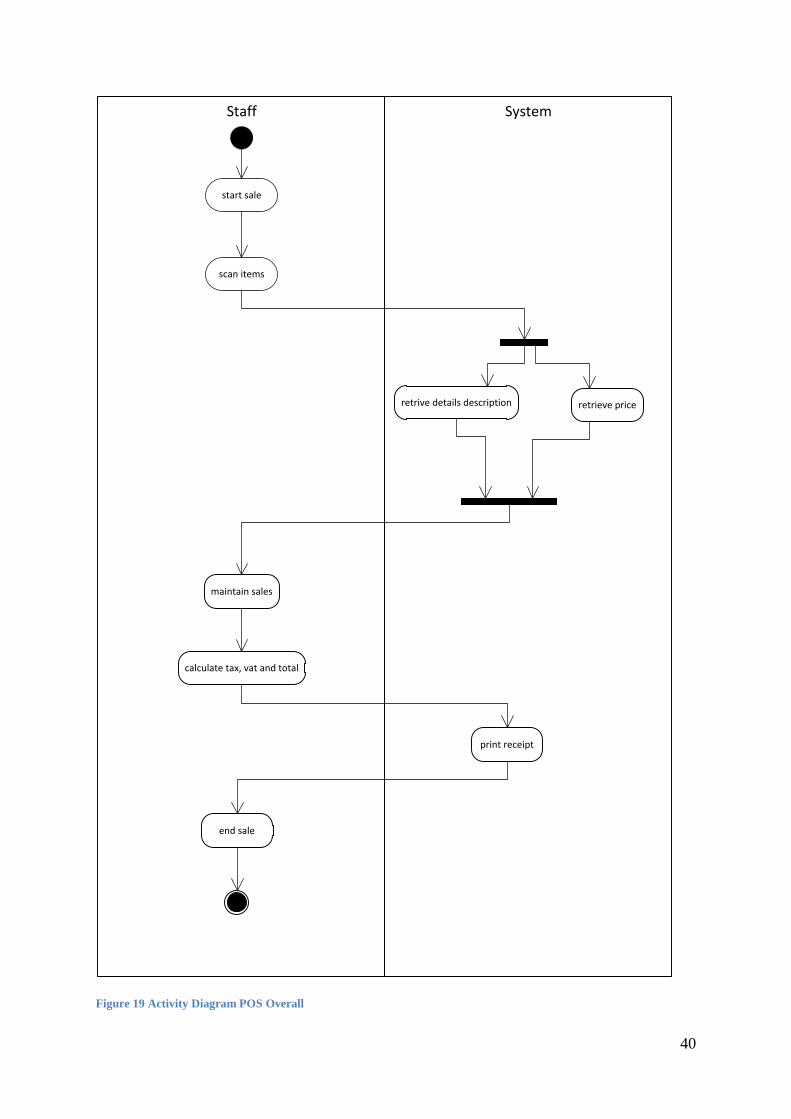
40
SystemStaff
start sale
scan items
retrive details description retrieve price
maintain sales
calculate tax, vat and total
print receipt
end sale
Figure 19 Activity Diagram POS Overall
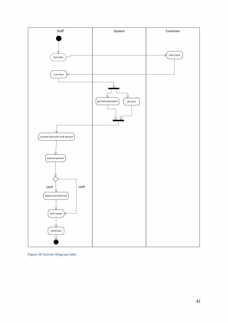
41
CustomerSystemStaff
start salesselect items
scan items
get items description get price
calculate total with vat & discount
received payment
deduct from RFID Card
print receipt
closed saes
card cash
Figure 20 Activity Diagram Sales
42
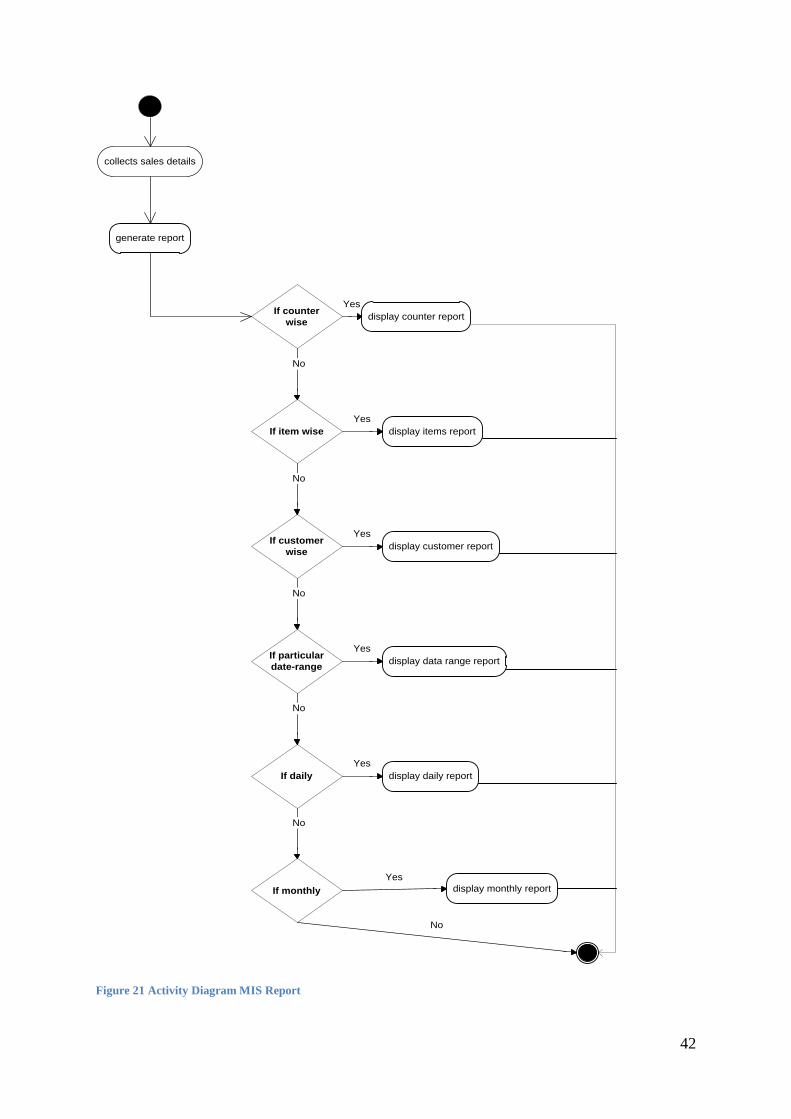
If counter
wise
Yes
No
If item wise
Yes
No
If customer
wise
Yes
No
If particular
date-range
Yes
If daily
No
Yes
No
If monthly
Yes
collects sales details
generate report
display items report
display customer report
display data range report
display daily report
display monthly report
No
display counter report
Figure 21 Activity Diagram MIS Report

43
Systemstaff
login
receive request for top-up amount
if customer = Member
insert amount
Yes
no
enter customer details
top-up card updated
Figure 22 Activity Diagram POS Top-Up

44
4.8 State Transition Diagram
System Idle
Adding Products
Payment
Deduce stock amount/print receipt
Compute totals amount
Manage payment
Start sales transaction
Read barcode/retrieve name & price
Figure 23 State Transition Diagram Sasto Mart
45
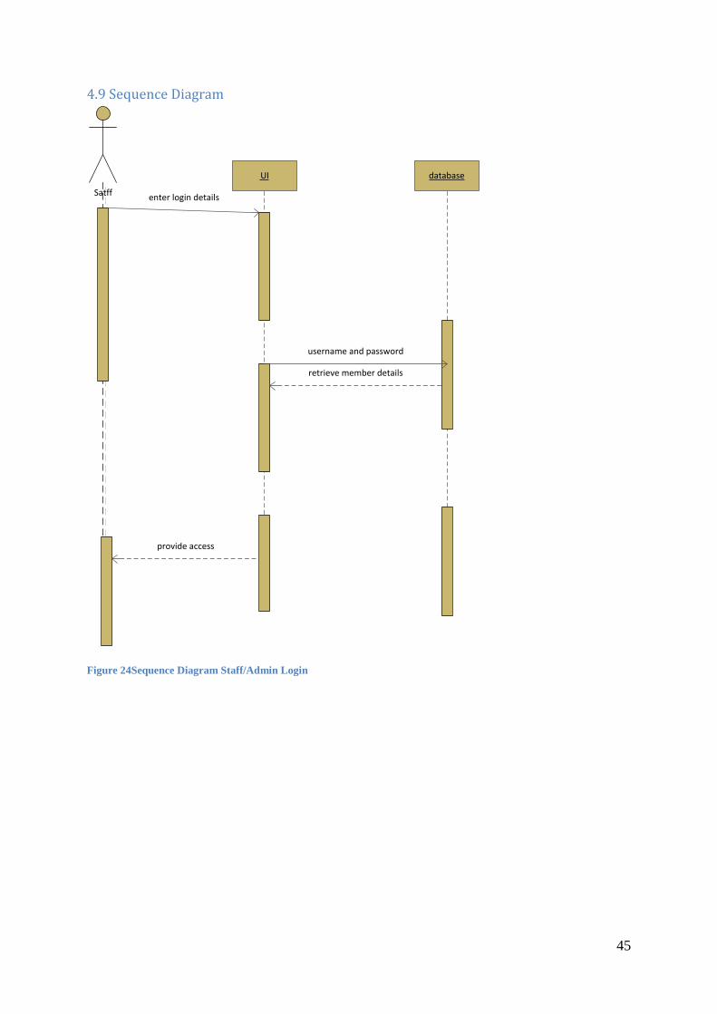
4.9 Sequence Diagram
UI
Satff
database
enter login details
username and password
retrieve member details
provide access
Figure 24Sequence Diagram Staff/Admin Login
46
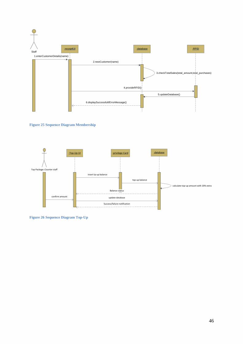
Staff
1.enterCustomerDetails(name)
:receiptlUI :database :RFID
2.newCustomer(name)
3.checkTotalSales(total_amount,total_purchases)
4.provideRFID()
5.updateDatabase()
6.displaySuccessfull/ErrorMessage()
Figure 25 Sequence Diagram Membership
:Top-Up UI :privilege Card :database
Top Package::Counter staff
insert tp-up balance
top-up balance
Balance status
Success/failure notification
calculate top-up amount with 20% extra
confirm amount update database
Figure 26 Sequence Diagram Top-Up
47
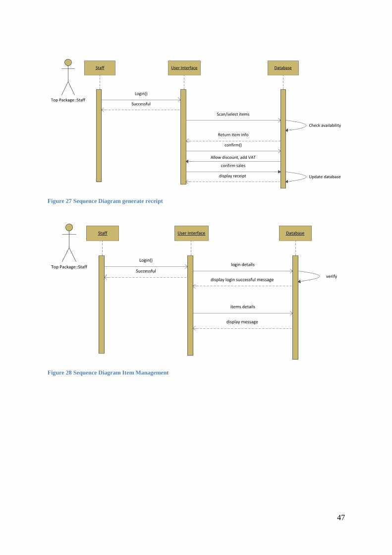
Staff User Interface Database
Top Package::Staff
Login()
Scan/select items
Successful
Return item info
Check availability
confirm()
Allow discount, add VAT
confirm sales
Update databasedisplay receipt
Figure 27 Sequence Diagram generate receipt
Staff User Interface Database
Top Package::Staff
Login()
items details
Successfulverify
display message
login details
display login successful message
Figure 28 Sequence Diagram Item Management

48
Login
login details
VerifyLogin Confirmation
request report
report ()
get report
check database
display report
display report
databaseManager
UI authentication
Figure 29 Sequence Diagram MIS

49
4.10 ER Diagram
user
PK userid
username password status userCol1 userCol2
sales
PK salesid
paymentmethod date discount total useridFK1 memberid salesCol1 salesCol2FK3 saleid
items
PK id
name price quantity itemcategoryCol1
member
PK memberid
name status cardno purchase no memberCol1
transaction
PK saleid
itemid quantity discount transactionCol1FK1 id
amounttopup
PK topupid
FK1 cardid amount amounttopupCol1
itemcategory
itemidFK2 categoryidFK1 id
category
PK categoryid
name status categoryCol1 categoryCol2 categoryCol3
card
PK cardid
amount statrus cardCol1 cardCol2 cardCol3
offer
PK offerid
title description amount offerCol1 offerCol2
Figure 30 ER Diagram
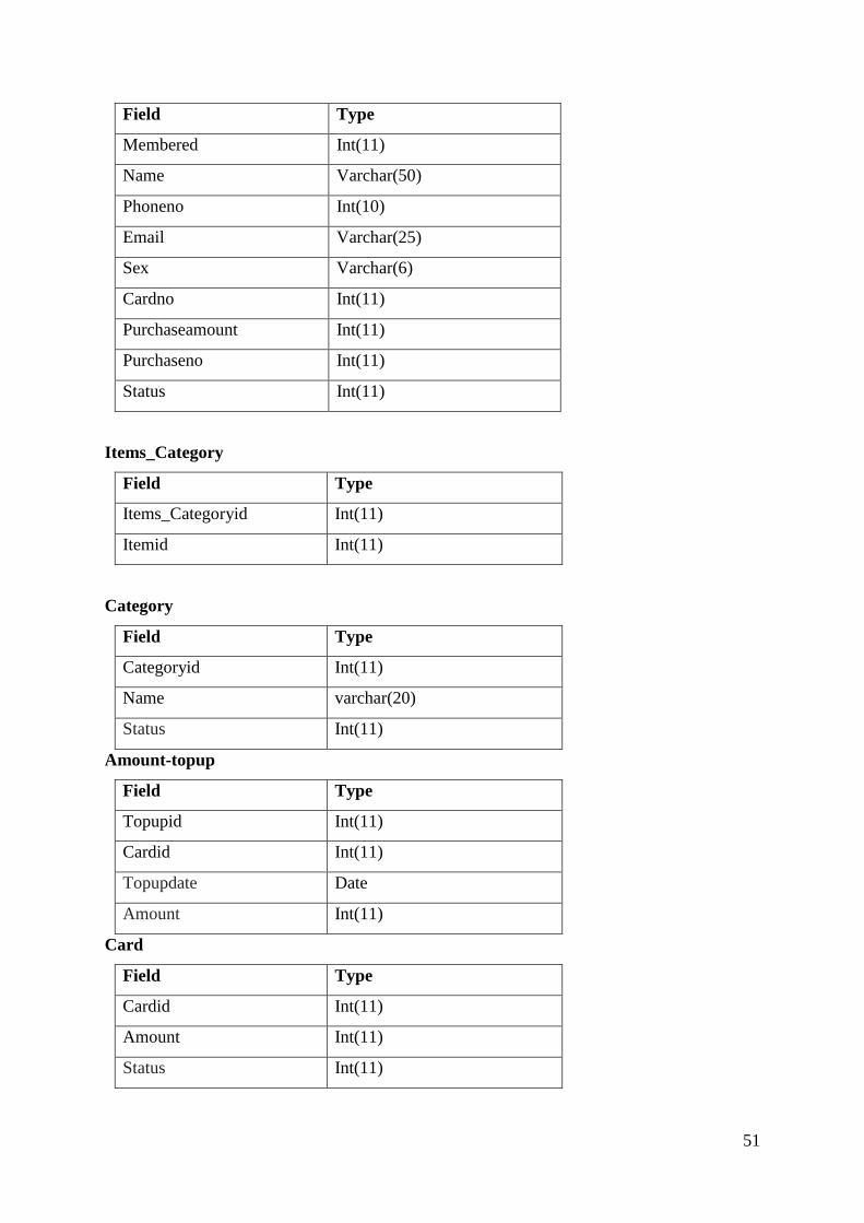
4.10.1 Data Dictionary
Items
Field Type
Id Int(11)
Name Varchar(25)
Price Int(11)
Quantity Int(11)
Status Int(11)
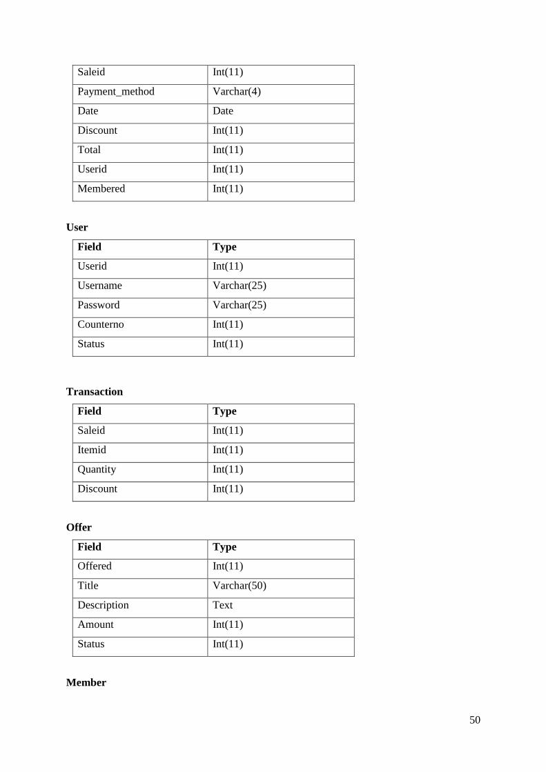
Sales
Field Type
50
Saleid Int(11)
Payment_method Varchar(4)
Date Date
Discount Int(11)
Total Int(11)
Userid Int(11)
Membered Int(11)
User
Field Type
Userid Int(11)
Username Varchar(25)
Password Varchar(25)
Counterno Int(11)
Status Int(11)
Transaction
Field Type
Saleid Int(11)
Itemid Int(11)
Quantity Int(11)
Discount Int(11)
Offer
Field Type
Offered Int(11)
Title Varchar(50)
Description Text
Amount Int(11)
Status Int(11)
Member
51
Field Type
Membered Int(11)
Name Varchar(50)
Phoneno Int(10)
Email Varchar(25)
Sex Varchar(6)
Cardno Int(11)
Purchaseamount Int(11)
Purchaseno Int(11)
Status Int(11)
Items_Category
Field Type
Items_Categoryid Int(11)
Itemid Int(11)
Category
Field Type
Categoryid Int(11)
Name varchar(20)
Status Int(11)
Amount-topup
Field Type
Topupid Int(11)
Cardid Int(11)
Topupdate Date
Amount Int(11)
Card
Field Type
Cardid Int(11)
Amount Int(11)
Status Int(11)
52
CHAPTER V – Testing Specifications
5.1 Introduction The main aspect of the testing during the software development process is to verify the
system as per the requirements of the system. The test plan is the execution plan for a testing
session. During the test plan various test case are generated in order to deliver the quality
product to the client. It is also refers as a documentation for the future aspect with the
developed programs or the software.
5.2Purpose The main purpose of this document is to provide test requirements and here are some of the
purposes of test case document:
1. To find unseen bugs in the system.
2. To fix the bugs determined with the software.
3. To assure the quality of the system.
4. To maintain the standard and customer requirements.
5. To ensure that functionality is working according to the requirements.

53
Test Plan
Unit Test
Test Plan
S.N. Test Cases Description
1. To test if the ‘authenticate’ function validates the user or not.
2. To test whether ‘offer’ menu allow store to add new offer package or not.
3. To test where ‘amount_topup’ menu stores the amount into card or not.
4. To test whether ‘item’ menu receives data from the form or not.
5. To test whether ‘category’ menu shows the items category or not.
6. To test whether ‘member’ menu adds the member or not.
7. To test whether ‘member’ menu shows the member or not.
8. To test if ‘report’ function shows the report or not.
9. To test if ‘sales’ menu show the interface to calculate the customer total or not
Test Cases
1. Test Case
No:
1
Test Case Description: To test if the ‘authenticate’ function validates the user or
not.
Test Data: Valid login information.
Expected Result: System shall authenticate the users with the correct login
details or display error message
Actual Result: System authenticate the user with correct details and
system display error message with wrong details
54
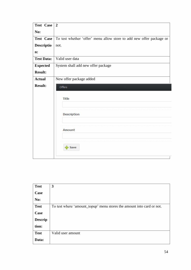
Test Case
No:
2
Test Case
Descriptio
n:
To test whether ‘offer’ menu allow store to add new offer package or
not.
Test Data: Valid user data
Expected
Result:
System shall add new offer package
Actual
Result:
New offer package added
Test
Case
No:
3
Test
Case
Descrip
tion:
To test where ‘amount_topup’ menu stores the amount into card or not.
Test
Data:
Valid user amount

55
Expecte
d
Result:
System shall stores the top-up amount to card
Actual
Result:
Top-up amount added
Test Case No: 4
Test Case
Description:
To test whether ‘item’ menu receives data from the form or
not.
Test Data: Valid user data.
Expected Result: System shall accept the data from the form

56
Actual Result: System accept the data from the form
Test Case
No:
5
Test Case
Description
:
To test whether ‘category’ menu shows the items category or not.
Test Data: Valid user data
Expected System shall display the category option

57
Result:
Actual
Result:
System display the category
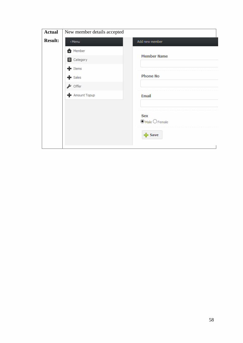
Test
Case
No:
6
Test
Case
Descrip
tion:
To test whether ‘member’ menu adds the member or not.
Test
Data:
New member details
Expect
ed
Result:
System shall accept the new member details
58
Actual
Result:
New member details accepted
59
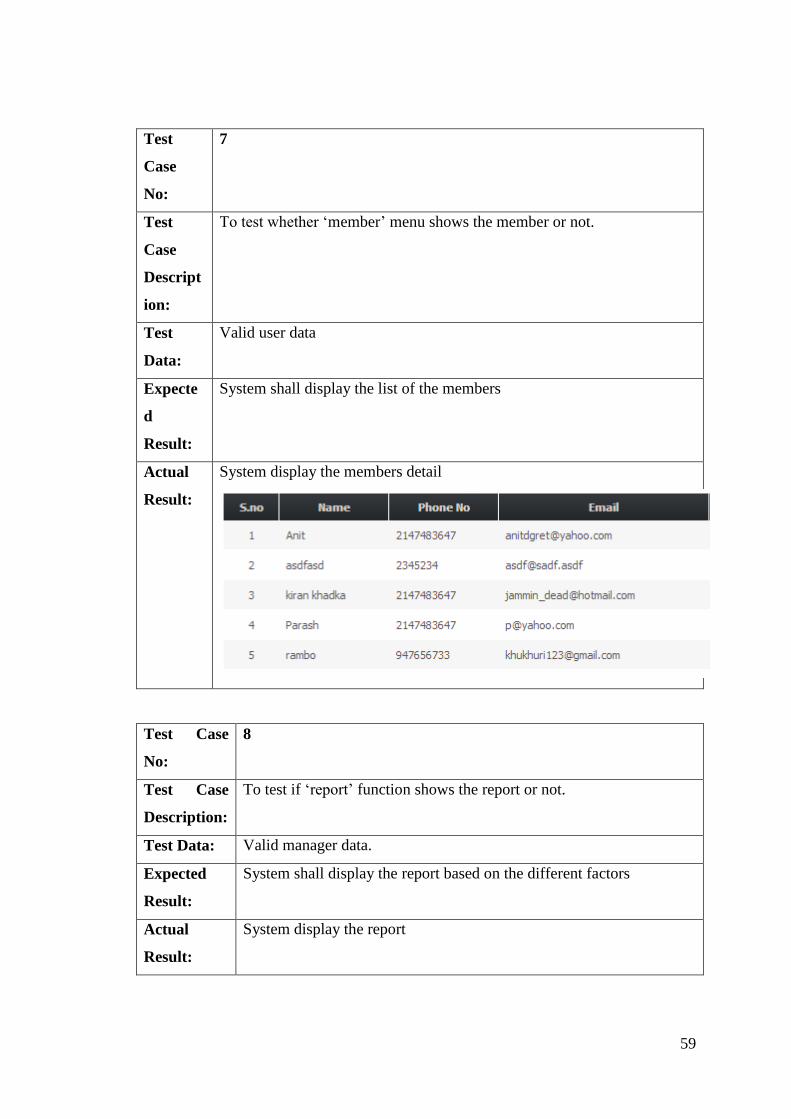
Test
Case
No:
7
Test
Case
Descript
ion:
To test whether ‘member’ menu shows the member or not.
Test
Data:
Valid user data
Expecte
d
Result:
System shall display the list of the members
Actual
Result:
System display the members detail
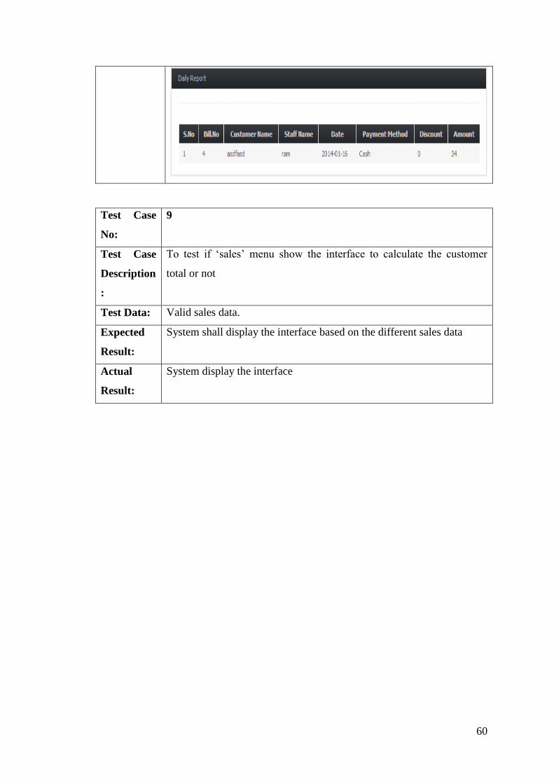
Test Case
No:
8
Test Case
Description:
To test if ‘report’ function shows the report or not.
Test Data: Valid manager data.
Expected
Result:
System shall display the report based on the different factors
Actual
Result:
System display the report
60
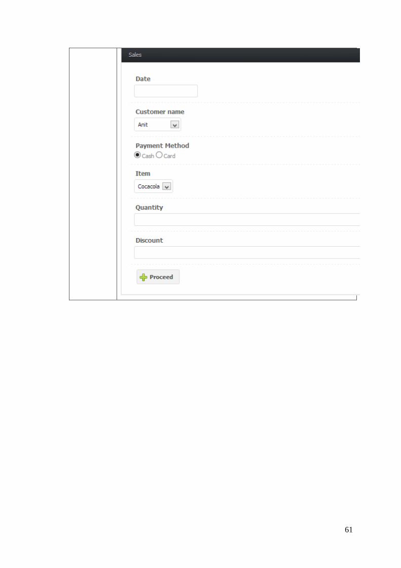
Test Case
No:
9
Test Case
Description
:
To test if ‘sales’ menu show the interface to calculate the customer
total or not
Test Data: Valid sales data.
Expected
Result:
System shall display the interface based on the different sales data
Actual
Result:
System display the interface
61
62
Test case Results
Test Case Result
1 Successful
2 Successful
3 Successful
4 Successful
5 Successful
6 Successful
7 Successful
8 Successful
9 Successful
Component Test
Test Plan
S.N. Test Cases Description
1. To test whether related user interface form is displayed or not after the successful
authentication process.
2. To test whether the password field encrypt the characters or not.
Component Test Cases
Test Case No: 1
Test Case Description: To test whether related user interface form is displayed or
not after the successful authentication process.
Test Data: Valid user login details
Expected Result: System shall display the related interface based on the user
type
Actual Result: System display the interface

63
Test Case No: 2
Test Case
Description:
To test whether the password field encrypt the characters or not.
Test Data: user login details
Expected
Result:
System shall encrypt the related login details (password)
Actual Result: System encrypt login details (password)

64
Component Test results
S.N. Test Cases Description Status
1. To test whether order form is displayed or not after the successful
authentication process.
Success
2. To test whether the password field encrypt the characters or not. Success
Validation Testing
Test Case 1
Objective To check what system display when username and password is
mismatch
Test Data Username and password
Expected Test Result System need to provide error message
Actual Test Result Error message displayed
Test Cases Objective
1 To check what system display when username and password is mismatch
2 To check whether the system accepts random card number or not
3 To check the quantity can a character or not
4 To check whether the item can be added without an quantity or not
65
Conclusion Successfully done.
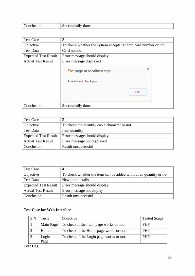
Test Case 2
Objective To check whether the system accepts random card number or not
Test Data Card number
Expected Test Result Error message should display
Actual Test Result Error message displayed
Conclusion Successfully done.
Test Case 3
Objective To check the quantity can a character or not
Test Data Item quantity
Expected Test Result Error message should display
Actual Test Result Error message not displayed
Conclusion Result unsuccessful
Test Case 4
Objective To check whether the item can be added without an quantity or not
Test Data New item details
Expected Test Result Error message should display
Actual Test Result Error message not display
Conclusion Result unsuccessful
Test Case for Web Interface
S.N Tests Objective Tested Script
1 Main Page To check if the main page works or not. PHP
2 Home To check if the Home page works or not. PHP
3 Login
Page
To check if the Login page works or not. PHP
Test Log
66
S.N Test
Objectives
Test Results
1 Test Case 1 Successful
2 Test Case 2 Successful
3 Test Case 3 Successful
System Testing
Test logs
S.N. Test Cases Description Status
1. To test whether a new item is created in database or not
upon filling up the new item form.
Success
2. To test whether system validates the admin user or not Success
3. To test whether user is added to the database or not upon
adding a new staff by the manager.
Success
Test Cases
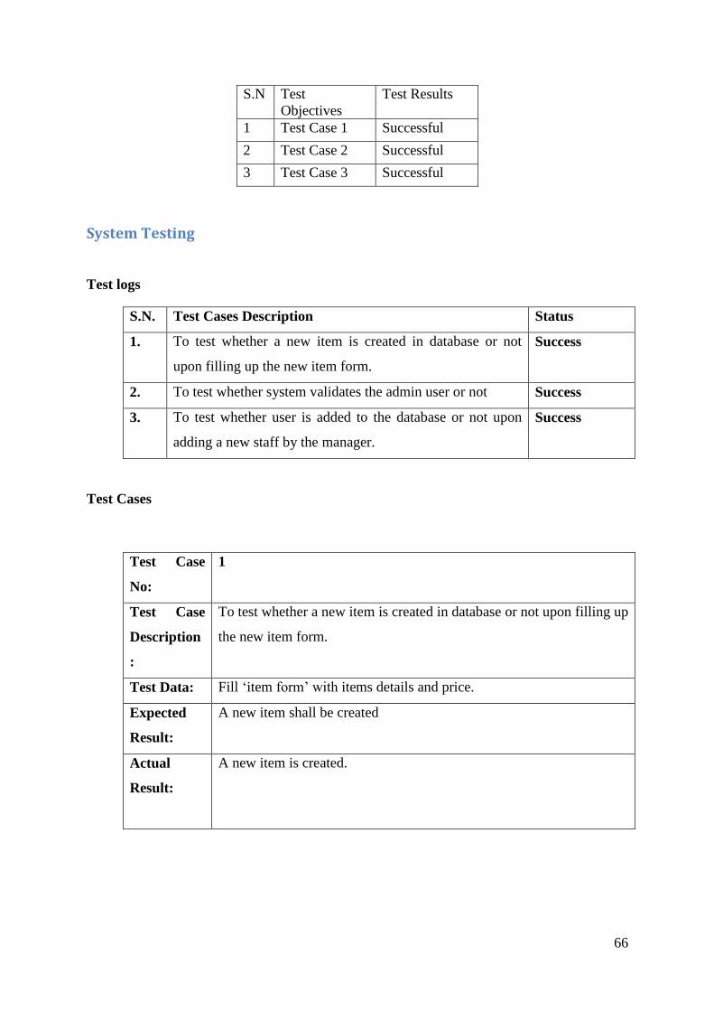
Test Case
No:
1
Test Case
Description
:
To test whether a new item is created in database or not upon filling up
the new item form.
Test Data: Fill ‘item form’ with items details and price.
Expected
Result:
A new item shall be created
Actual
Result:
A new item is created.
67
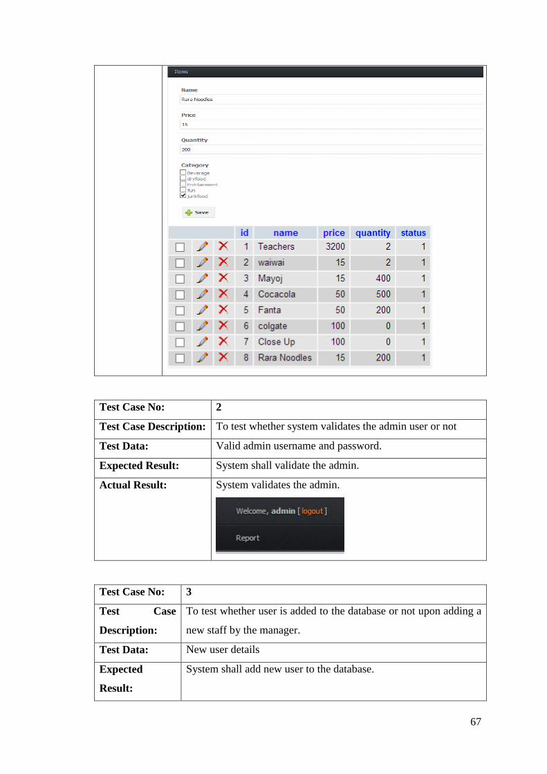
Test Case No: 2
Test Case Description: To test whether system validates the admin user or not
Test Data: Valid admin username and password.
Expected Result: System shall validate the admin.
Actual Result: System validates the admin.
Test Case No: 3
Test Case
Description:
To test whether user is added to the database or not upon adding a
new staff by the manager.
Test Data: New user details
Expected
Result:
System shall add new user to the database.

68
Actual Result: System updates the database.
Test Results
S.N. Test Cases Description Status
1. To test whether a new item is created in database or not
upon filling up the new item form.
Success
2. To test whether system validates the admin user or not Success
3. To test whether user is added to the database or not upon
adding a new staff by the manager.
Success
69
SYSTEM EVALUATION
Introduction
This part portrays the criticalness of provision assessment in reference to the task. The
principle destination of this part is to check if the provision has reached its necessities and fit
for executing it. This section incorporates how the results were completed throughout
actualizing results and talk of the assessment on the venture and its conclusions.
Evaluation Overview
The assessment of the venture is carried out against the task scope. The main aim and
objective of the project extension was installing it in individual stall, add to cart, discount,
and create bargains report and so on. The study on the usage of the task will be functional as
it will help us to handle with the issues and assess the data recovered from the issues
confronted.
Evaluation of Project Deliverables
The fundamental motivation behind the execution of the proposed web provision is to
help to make costumer and salesman simpler on their direction and likewise spare time and to
decrease redundancy error.
System Evaluation
The system evaluation of the requisition is carried out as per the necessities of the
provision. The useful evaluation of the task will discover the functional requirements of the
project and likewise the implementation of the capacities. The advancement of the project
ought to have the ability to furnish proportional payback necessities of the system.
Criteria
The criteria for the assessment of the project will verify the generally speaking parts of the
system.
70
PROJECT CONCLUSION
At long last, we assembly of five have finished the System advancement and
documentation for "Sasto Mart". At that point we have chosen a particular methodology
“iterative waterfall model” for the advancement of the system. We likewise have given the
explanation behind choosing it by contrasting it with different methodologies.
For the improvement of the system we have utilized Xamp as a server as it is an open
source cross-platform web server and its free of cost. This incorporates MySQL database and
translators for scripts composed in PHP customizing dialect. We have utilized Adobe
Dreamweaver for the advancement of the provision utilizing PHP. Dreamweaver is a web
improvement requisition and PHP as a Server side HTML entrenched scripting language
which gives us the complete suite for making this web based application.
On outlining the provision, we have initially portrayed the stream of the project as per
the situation provided for us. At that point we draw the conceivable case outline likewise with
activity and sequence diagram. These diagrams indicate the full working of the project and its
stream. Distinctive attributes and entities are recorded and the database needed for this
system is diagrammed. Other diagrams like peer chart is attracted to know the basic way for
the task and Gantt diagram for the evaluated time span for the completion of the undertaking
for advancement and documentation. The interface is designed and is characterized with the
functionalities included.
We have improved the provision where we can screen the total sales by creating the
deals report of each one counter of “Sasto Mart. Finally the project is tried through object
testing and interface testing system. At that point general experiments are recorded with their
goals and the results of the test cases. Then the assessment of the system improved is carried
out in addition to its criteria and its practices.
We have attempted to finish the system improvement as required by the prerequisites
that have been specified. We have not utilized the RFID mechanism to read the client's card
ID. Rather in utilizing the ID of the card created, we need to furnish the card ID physically in
the system for obtaining the items.
Server Installation 1. Find XAMPP Server installation file in Utility CD. Execute that file and select
directory to install XAMPP in your computer.

71
2. After successful installation of XAMPP, find Xampp control.exe in Drive where you
install or using short cut key in your desktop. After getting control panel, press start
button at the side of Apache and MySQL.
When you execute xampp control.exe After you press start
3. Click Both Admin button to ensure that you have correctly installed server and
database to run the application.
When clicked Apache ADMIN button
When Clicked MySQL ADMIN button
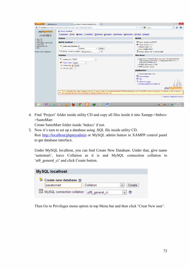
72
4. Find ‘Project’ folder inside utility CD and copy all files inside it into Xampp->htdocs-
>SastoMart
Create SastoMart folder inside ‘htdocs’ if not.
5. Now it’s turn to set up a database using .SQL file inside utility CD.
Run http://localhost/phpmyadmin or MySQL admin button in XAMPP control panel
to get database interface.
Under MySQL localhost, you can find Create New Database. Under that, give name
‘sastomart’, leave Collation as it is and MySQL connection collation to
‘ut8_general_ci’ and click Create button.
Then Go to Privileges menu option in top Menu bar and then click ‘Creat New user’.
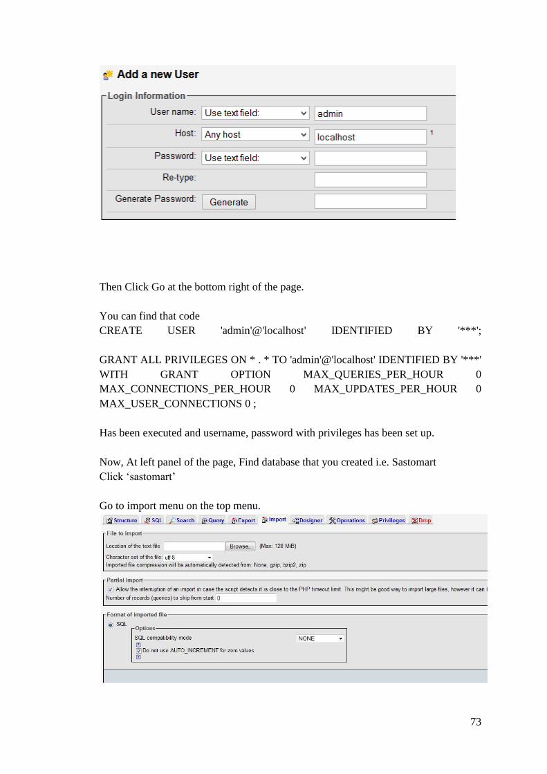
73
Then Click Go at the bottom right of the page.
You can find that code
CREATE USER 'admin'@'localhost' IDENTIFIED BY '***';
GRANT ALL PRIVILEGES ON * . * TO 'admin'@'localhost' IDENTIFIED BY '***'
WITH GRANT OPTION MAX_QUERIES_PER_HOUR 0
MAX_CONNECTIONS_PER_HOUR 0 MAX_UPDATES_PER_HOUR 0
MAX_USER_CONNECTIONS 0 ;
Has been executed and username, password with privileges has been set up.
Now, At left panel of the page, Find database that you created i.e. Sastomart
Click ‘sastomart’
Go to import menu on the top menu.
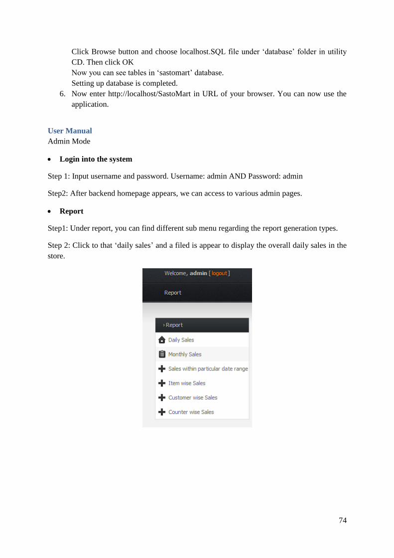
74
Click Browse button and choose localhost.SQL file under ‘database’ folder in utility
CD. Then click OK
Now you can see tables in ‘sastomart’ database.
Setting up database is completed.
6. Now enter http://localhost/SastoMart in URL of your browser. You can now use the
application.
User Manual
Admin Mode
Login into the system
Step 1: Input username and password. Username: admin AND Password: admin
Step2: After backend homepage appears, we can access to various admin pages.
Report
Step1: Under report, you can find different sub menu regarding the report generation types.
Step 2: Click to that ‘daily sales’ and a filed is appear to display the overall daily sales in the
store.

75
Reference 24point0. (n.d.). Rapid Application Development. Retrieved 12 01, 2013, from
http://www.24point0.com/ppt-shop/rapid-application-development-powerpoint/
istqbexamcertification. (n.d.). Retrieved 12 01, 2013, from
http://istqbexamcertification.com/what-is-incremental-model-advantages-
disadvantages-and-when-to-use-it/
istqbexamcertification. (n.d.). ISTQB Exam Certification. Retrieved 12 01, 2013, from
http://istqbexamcertification.com/what-is-prototype-model-advantages-disadvantages-
and-when-to-use-it/
Purcell, J. (2008). Comparison of software development lifecycle methodologies, 2-6.
Rouse, M. (2007). What is waterfall model? - Definition from WhatIs.com. Retrieved 11 26,
2013, from http://searchsoftwarequality.techtarget.com/definition/waterfall-model
Sky, S. (2007). Waterfall Method Software Development Life Cycle. Retrieved 11 26, 2013,
from http://skysigal.xact-
solutions.com/Resources/SoftwareDevLifeCycle/WaterfallMethodSDLC/tabid/600/D
efault.aspx
technologies, r. i. (2007). client server architecture. Retrieved 12 11, 2013, from
http://www.roseindia.net/java/network/client-server.shtml

76