software development methodologies - sharifsharif.edu/~ramsin/index_files/sdmlecture3.pdfstructures,...
TRANSCRIPT

Department of Computer Engineering1
Sharif University of Technology
Software Development
Methodologies
Lecturer: Raman Ramsin
Lecture 3
Seminal Object-Oriented Methodologies:
A Feature-Focused Review

Software Development Methodologies – Lecture 3
Department of Computer Engineering2
Sharif University of Technology
Responsibility-Driven Design (RDD)
Introduced in 1990; a UML-based and use-case driven version was released in 2002.
The process starts when a detailed requirements specification of the system has already been provided.
The system is modeled as a collection of objects that collaborate to fulfill their responsibilities.
Responsibilities include two key items:
The knowledge an object maintains.
The actions an object can perform.

Software Development Methodologies – Lecture 3
Department of Computer Engineering3
Sharif University of Technology
RDD: Process The process is divided into two phases:
Exploratory Phase: classes and their responsibilities and collaborations are identified.
Analysis Phase: subsystems and class details are specified.
[Wirfs-Brock et al. 1990]

Software Development Methodologies – Lecture 3
Department of Computer Engineering4
Sharif University of Technology
RDD: Exploratory Phase
The major tasks to be iteratively performed in this phase are: Discovering the classes required to model the application Determining what behavior the system is responsible for and assign these responsibilities
to specific classes Determining what collaborations must occur between classes of objects to fulfill the
responsibilities.
Results are modeled in CRC (Class-Responsibility-Collaborator) cards
CRC Card
[Wirfs-Brock et al. 1990]

Software Development Methodologies – Lecture 3
Department of Computer Engineering5
Sharif University of Technology
RDD: Analysis Phase
Major tasks to be performed in this phase:
Factoring the responsibilities into inheritance hierarchies modeled in Inheritance Graphs, and identifying class contracts
Identifying possible subsystems of objects and modeling them and their client-server relationships in Collaboration Graphs
Determining Class Protocols (method signatures) and completing a specification of classes, subsystems of classes, and client-server contracts

Software Development Methodologies – Lecture 3
Department of Computer Engineering6
Sharif University of Technology
RDD: Analysis Phase
Collaboration Graph
[Wirfs-Brock et al. 1990]

Software Development Methodologies – Lecture 3
Department of Computer Engineering7
Sharif University of Technology
Booch
Introduced, purely as a design method, in 1991 [Boo91]; extended version, which also covered analysis, was introduced in 1994.
Process designed as a repeating process (referred to as “The Micro Process”) within a lifecycle-level repeating process (referred to as “The Macro Process”).
The macro process serves as a controlling framework for the micro process.

Software Development Methodologies – Lecture 3
Department of Computer Engineering8
Sharif University of Technology
Booch: Macro Process
Represents the activities of the development team on the scale of weeks to months.
Many parts of this process are basic software management practices such as quality assurance, code walkthroughs, and documentation.
The focus at this level is more upon the customers and their desires for things such as quality, completeness, and scheduling.
[Booch 1994]

Software Development Methodologies – Lecture 3
Department of Computer Engineering9
Sharif University of Technology
Booch: Micro Process
Driven by scenarios and architectural specifications that emerge from the macro process
Represents the daily activities of the individual or small group of developers
[Booch 1994]

Software Development Methodologies – Lecture 3
Department of Computer Engineering10
Sharif University of Technology
Object Modeling Technique (OMT)
Introduced by Rumbaugh et al. in 1991
Categorized as combinative [MP92], since it is based on three different models and defines a method for integrating them.
Object Model (OM): depicts object classes in the system and their relationships, as well as their attributes and operations, in a Class Diagram
Dynamic Model (DM): indicates the dynamics of the objects, their changes in state and the flow of events; captured in Event-Trace Diagrams and State Transition Diagrams (State Charts)
Functional Model (FM): a hierarchical set of Data Flow Diagrams (DFDs) of the system

Software Development Methodologies – Lecture 3
Department of Computer Engineering11
Sharif University of Technology
OMT Process
[Rumbaugh et al. 1991]

Software Development Methodologies – Lecture 3
Department of Computer Engineering12
Sharif University of Technology
OMT Process: Analysis Phase
The goal is to build a correct and comprehensible model of the real world.
Once the initial problem is defined, the following tasks are carried out:
Building the object model, including a Class Diagram and a Data Dictionary.
Developing the dynamic model, including State Transition Diagrams and global Event-Trace Diagrams
Constructing the functional model including Data Flow Diagrams and constraints
Verifying, iterating, and refining the three models.

Software Development Methodologies – Lecture 3
Department of Computer Engineering13
Sharif University of Technology
OMT Process: Analysis Phase
Class Diagram
[Rumbaugh et al. 1991]

Software Development Methodologies – Lecture 3
Department of Computer Engineering14
Sharif University of Technology
OMT Process: Analysis Phase
Event-Trace Diagram
[Rumbaugh et al. 1991]

Software Development Methodologies – Lecture 3
Department of Computer Engineering15
Sharif University of Technology
OMT Process: Analysis Phase
State Transition Diagram
[Rumbaugh et al. 1991]

Software Development Methodologies – Lecture 3
Department of Computer Engineering16
Sharif University of Technology
OMT Process: Analysis Phase
Data Flow Diagram
[Rumbaugh et al. 1991]

Software Development Methodologies – Lecture 3
Department of Computer Engineering17
Sharif University of Technology
OMT Process: System Design
High-level structure of the system is defined
Tasks include: Organizing the system into subsystems
Identifying concurrency
Allocating subsystems to processors and tasks
Choosing the strategy for implementing data stores in terms of data structures, files, and databases
Identifying global resources and determining mechanisms for controlling access to them
Choosing an approach to implementing software control
Considering boundary conditions
Establishing trade-off priorities

Software Development Methodologies – Lecture 3
Department of Computer Engineering18
Sharif University of Technology
OMT Process: Object Design
Concerned with fully specifying the existing and remaining classes, associations, attributes, and operations necessary for implementing the system
Operations and data structures are fully defined along with any internal objects needed for implementation
All details for fully determining how the system will be implemented are specified

Software Development Methodologies – Lecture 3
Department of Computer Engineering19
Sharif University of Technology
Object-Oriented Software Engineering (OOSE)
First introduced by Jacobson et al. in 1992
A simplified version of Jacobson’s Objectorymethodology, first introduced in 1987 and later the property of Rational Corporation (now acquired by IBM)
Covers the full generic lifecycle

Software Development Methodologies – Lecture 3
Department of Computer Engineering20
Sharif University of Technology
OOSE: Process Analysis: focusing on understanding the system and creating a
conceptual model. Consists of two non-sequential, iterative subphases:
Requirements Analysis, aiming at eliciting and modeling the requirements of the system. A Requirements Model is produced.
Robustness Analysis, aiming at modeling the structure of the system. An Analysis Model is produced.
Construction: focusing on creating a blueprint of the software and producing the code. Consists of two subphases:
Design, aiming at modeling the run-time structure of the system, and also the inter-object and intra-object behaviour. A Design Model is produced.
Implementation, aiming at building the software. An Implementation Model(including the code) is produced.
Testing: focusing on verifying and validating the implemented system. A Test Model is produced.

Software Development Methodologies – Lecture 3
Department of Computer Engineering21
Sharif University of Technology
OOSE: Process
[Jacobson et al. 1992]

Software Development Methodologies – Lecture 3
Department of Computer Engineering22
Sharif University of Technology
OOSE: Analysis – Requirements Analysis
Aim: Specify and model the functionality required of the system, typical means and forms of interacting with the system, and the structure of the problem domain.
The model to be developed is the Requirements Model, further divided into three submodels:
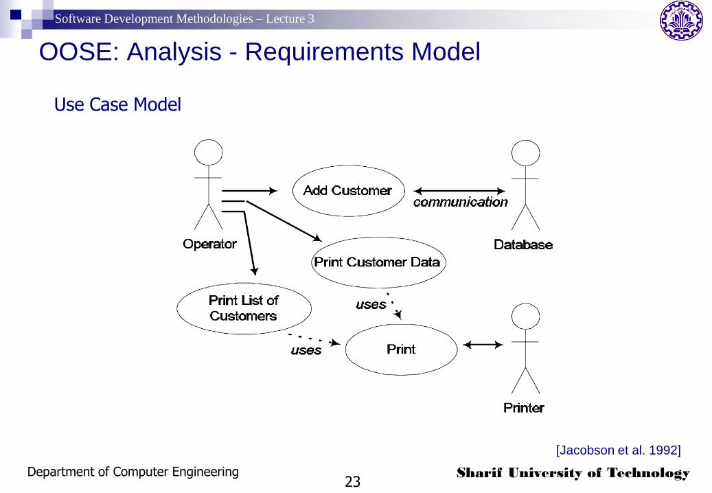
A Use Case Model: which delimits the system and describes the functional requirements from the user’s perspective.
A Domain Object Model: consists of objects representing entities derived from the problem domain, and their inheritance, aggregation and association relationships.
Interface Descriptions: provide detailed logical specifications of the user interface and interfaces with other systems.
Software Development Methodologies – Lecture 3
Department of Computer Engineering23
Sharif University of Technology
OOSE: Analysis - Requirements Model
[Jacobson et al. 1992]
Use Case Model

Software Development Methodologies – Lecture 3
Department of Computer Engineering24
Sharif University of Technology
OOSE: Analysis - Requirements Model
[Jacobson et al. 1992]
Domain Object Model

Software Development Methodologies – Lecture 3
Department of Computer Engineering25
Sharif University of Technology
OOSE: Analysis – Robustness Analysis
Aim: Map the Requirements Model to a logical configuration of the system that is robust and adaptable to change.
The model to be developed is the Analysis Model: Shows how the functionality of each and every use case is realized by
collaboration among typed objects (called Analysis Objects). Shows the subsystems of the system.
Analysis Objects can be of three types: Entity: Represent entities with persistent state, typically outliving the use
cases they help realize. They are usually derived from the domain object model.
Interface: Represent entities that manage transactions between the system and the actors in the outside world.
Control: Represent functionality not inherently belonging to other types of objects. They typically act as controllers or coordinators of the processing going on in the use cases.

Software Development Methodologies – Lecture 3
Department of Computer Engineering26
Sharif University of Technology
OOSE: Analysis - Analysis Model
[Jacobson et al. 1992]
Analysis Model

Software Development Methodologies – Lecture 3
Department of Computer Engineering27
Sharif University of Technology
OOSE: Construction - Design
Aim: Refine the Analysis Model by taking into account implementation features.
The model to be developed is the Design Model:
describes the features of the implementation environment
describes the details of the design classes (referred to as blocks) necessary to implement the system
describes the way run-time objects should behave and interact in order to realize the use cases

Software Development Methodologies – Lecture 3
Department of Computer Engineering28
Sharif University of Technology
OOSE: Construction - Design
Three Subphases:
1. Determination of the features of the implementation environment (DBMS, programming language features, distributionconsiderations,…)
2. Definition of blocks (design classes) and their structure: 1. Each object in the Analysis Model is mapped to a block.
2. Implementation-specific blocks are added and the collection is revised.
3. Interfaces and semantics of operations are defined.
3. Specification of the sequences of interactions among objects and the dynamic behaviour of each block:1. An Interaction Diagram is drawn for each of the use cases.
2. A State Transition Graph is used for describing the behaviour of each block.

Software Development Methodologies – Lecture 3
Department of Computer Engineering29
Sharif University of Technology
OOSE: Construction - Design Model
[Jacobson et al. 1992]
Interaction Diagram

Software Development Methodologies – Lecture 3
Department of Computer Engineering30
Sharif University of Technology
OOSE: Construction - Implementation
Aim: Produce the code from the specifications of the packages and blocks defined in the design model.
The model to be developed is the Implementation Model, which consists of the actual source code and accompanying documentation.

Software Development Methodologies – Lecture 3
Department of Computer Engineering31
Sharif University of Technology
OOSE: Testing
Aim: Verify and validate the implementation model
The model to be developed is the Testing Model, which mainly consists of: Test plan
Test specifications
Test results.
Testing is done at three levels, starting from the lowest level: blocks are tested first
Use cases are tested next
Finally, tests are performed on the whole system

Software Development Methodologies – Lecture 3
Department of Computer Engineering32
Sharif University of Technology
OOSE: Pivotal role of the Use Case Model
[Jacobson et al. 1992]

Software Development Methodologies – Lecture 3
Department of Computer Engineering33
Sharif University of Technology
References
Wirfs-Brock, R., Wilkerson, B., Wiener, R., Designing Object-Oriented Software. Prentice-Hall, 1990.
Booch, G., Object Oriented Analysis and Design with Applications (2nd Edition). Benjamin/Cummings, 1994.
Rumbaugh, J., Blaha, M., Premerlani, W., Eddy, F., Lorensen, W., Object-Oriented Modeling and Design. Prentice-Hall, 1991.
Jacobson, I., Christerson, M., Jonsson, P., Övergaard, G., Object-Oriented Software Engineering: A Use Case Driven Approach. Addison-Wesley, 1992.