software architecture - eth...
TRANSCRIPT

Chair of Software Engineering
Software Architecture
Lecture 16: UML – Unified Modeling Language
Bertrand Meyer, Carlo A. Furia, Martin Nordio (Christian Estler)
ETH Zurich, February-May 2011

2
Why do we need models?
Problem domain
Code
Implementation
Ideal world...
Problem domain
Implementation
Reality
Code

3
Why do we need models?
Models are abstractions of „the real thing“
They hide complexity by looking at a problem from a certain perspective
Focus on relevant parts
Ignoring irrelevant details
What is relevant depends on the model
Example: to model the main components of a car, we do not need internal details of the engine.
Problem domain
Code
Model
abstract from
abstract from

4
Why model software?
Why is code itself not a good model?
Software is getting increasingly more complex
Windows XP: ~40 millions lines of code
A single programmer cannot manage this amount of code in its entirety
Code is not easily understandable by developers who did not write it
We need simpler representations for complex systems
Modeling is a means for dealing with complexity
5
UML - Unified Modeling Language
Unified Modeling Language (UML)
General purpose modeling language (for [OO software] systems)
Today‟s de-facto standard in Industry
Sine ‟97, UML is defined/evolved by the Object Management Group (OMG)
Founded 1989 by IBM, Apple, Sun, …
Microsoft joined 2008
Today more than 800 members

6
UML - Unified Modeling Language
Authors: The Three Amigos
Grady Booch James Rumbaugh Ivar Jacobson

7
Why “Unified” Modeling Language?

8
What is UML?
Specification: the language is supposed to be simple enough to be understood by the clients
Visualization: models can be represented graphically
Construction: the language is supposed to be precise enough to make code generation possible
Documentation: the language is supposed to be widespread enough to make your models understandable by other developers
UML is a standardized language for specifying, visualizing, constructing and documenting
(software) systems

9
What is UML?
UML defines
Entities of models and their (possible) relations
Different graphical notations to visualize structure and behavior
A model in UML consist of
Diagrams
Documentation which complements the diagrams
10
What UML is not !
Programming language
this would bound the language to a specific computing architecture
however code generation is encouraged
Software development process
Choose your own process, (e.g. Waterfall-model, V-model, …)
Use UML to model & document
CASE tool specification
however tools do exist: Sun, IBM Rose, Microsoft Visio, Borland Together etc.

11
Diagrams in UML
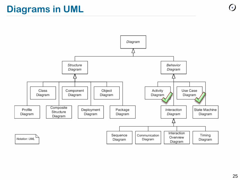
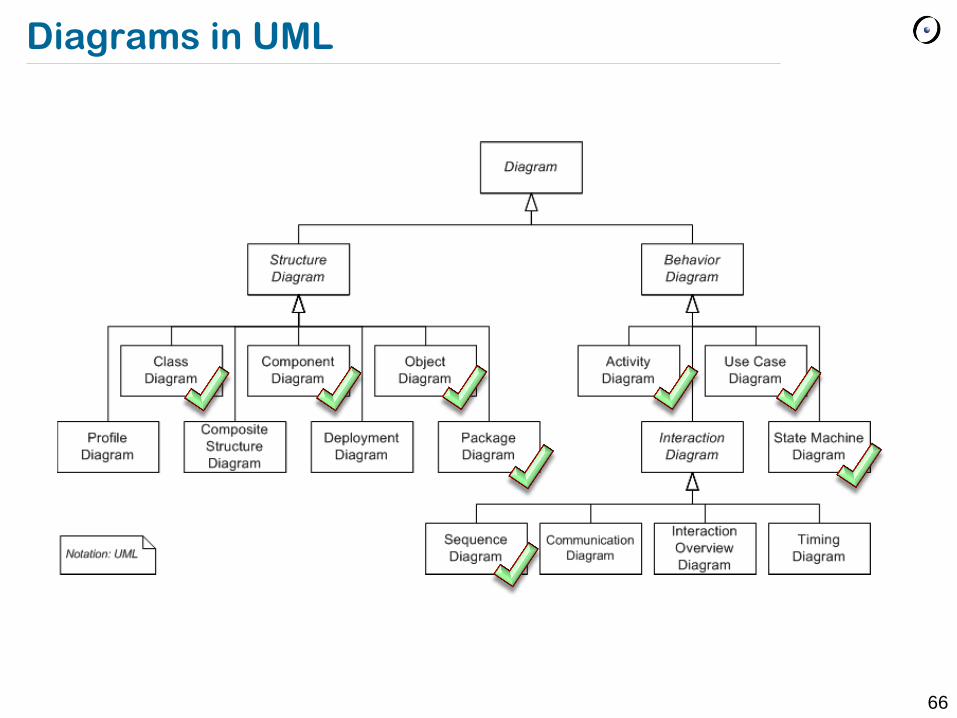
UML currently defines 14 types of diagrams
7 types of Structure Diagrams
7 types of Behavior Diagrams
Different diagrams provide different levels of abstraction
High-level structure vs. low-level structure
Example: components vs. objects
High-level behavior vs. low-level behavior
Example: use-case vs. feature-call sequence

12
Diagrams in UML

13
Case study*
ETH cafeteria wants to introduce a card-based payment system
Students upload money to their card using a special automaton (similar to an ATM)
Using their cards, students pay cashless in the cafeteria
* inspired by: http://www.fbi.h-da.de/labore/case/uml.html

14
Use Case diagram
Use Case diagrams
High-level abstraction of the system„s external behavior
From the client„s perspective
What the client plans to do with the system
Basic elements of a Use Case diagram:
Actor name
Use Case name
System name
Task that should be
executed by the planned
system
Person or System that
interacts with the planned
system
Boundaries of the planned
system

15
Use Case diagram - Example
Use Case diagram for the payment system
Pay Food
Client Load Card
Log Transaction
<<include>>
<<include>>
Caf_Pay
Teller
Accounting
Association between Actor and Use Case
Stereotype
Dependency between Use Cases

16
Use Case diagrams: include-association
<<include>> stereotype to include use cases:
reusing common functionality, no duplicates
“Pay Food” and “Load Card” use the functionality provided by “Log Transaction”
Pay Food
Client
Load Card Log
Transaction
<<include>>
<<include>>
17
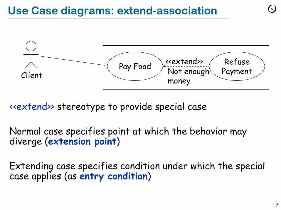
Use Case diagrams: extend-association
<<extend>> stereotype to provide special case Normal case specifies point at which the behavior may diverge (extension point) Extending case specifies condition under which the special case applies (as entry condition)
Pay Food Client
Refuse Payment
<<extend>> Not enough money
18
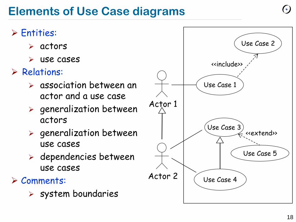
Elements of Use Case diagrams
Entities:
actors
use cases
Relations:
association between an actor and a use case
generalization between actors
generalization between use cases
dependencies between use cases
Comments:
system boundaries
Actor 1
Use Case 1
Actor 2
Use Case 3
Use Case 4
Use Case 2
<<include>>
Use Case 5
<<extend>>
19
Use Case specification
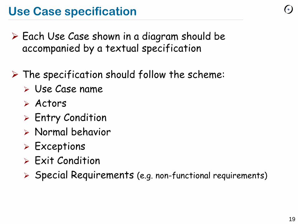
Each Use Case shown in a diagram should be accompanied by a textual specification
The specification should follow the scheme:
Use Case name
Actors
Entry Condition
Normal behavior
Exceptions
Exit Condition
Special Requirements (e.g. non-functional requirements)

20
Use Case specification
Example for „ Pay Food“ Use Case
Name: Pay Food
Actors: Client, Teller
Entry Condition: Client has food and wants to pay it
Normal behavior: Teller types in food; Total amount is shown on display; Client puts card into reading device; Amount gets withdrawn; If not enough money on card, then an error message is shown; Return card to client
Exceptions: If card is not readable, then show error message and return card; If power failure while card in reading device, wait until power is back and return card – payment needs to be redone
Exit Condition: Client has paid the food and gets the card back

21
Diagrams in UML

22
Activity diagrams
Activity diagrams are used to model (work)flows
They are used visualize complex behavior, e.g.
Business process
Algorithms (though less common)
Tokens are used to determine the flow, similar to Petri-nets
A common usage: detailed modeling of Use Cases

23
Elements of Activity diagrams
Action: atomic element, no further splitting possible
Activity: can contain activities, actions, control nodes
Control nodes: used to denote control struture in the flowgraph
Action name
Action2
Action1 In-Param
activity name
Out-Param
Allows refinement
Initial node: start of a flow
Splitting node
Synchronization node
End node: terminates the
activity
Decision- / Merging node
24
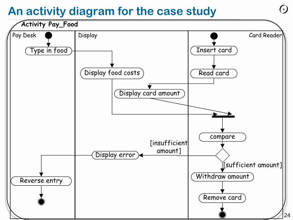
An activity diagram for the case study
Type in food
Activity Pay_Food
Display food costs
Display card amount
Read card
Insert card
compare
Withdraw amount
Remove card
Display error
Reverse entry
[sufficient amount]
[insufficient amount]
Pay Desk Display Card Reader
25
Diagrams in UML

26
UML Class diagrams
Keep in mind:
Use Cases represent an external view of the system‟s behavior
Classes represent inner structure of the system
No correlation between use cases and classes
Class diagrams are used at different levels of abstraction with different levels of details
Early phase: identifying classes and their relations in the problem domain (high-level, no implementation details)
Implementation phase: high level of detail (attributes, visibility, …), all classes relevant to implement the system

27
Classes
A class encapsulates state (attributes) and behavior (operations)
Each attribute has a type
Each operation has a signature
The class name is the only mandatory information
Cafeteria_Card amount : Float Id: String
get_amount(): Integer get_id(): String withdraw( Integer )
Name
Type
Signature
Operations
Attributes

28
More on classes
Valid UML class diagrams
Corresponding BON diagram
No distinction between attributes and operations (uniform access principle)
Cafeteria_Card
Amount id get_amount() get_id()
Cafeteria_Card
Cafeteria_Card
get_amount get_id
NONE Amount id

29
More on classes
Abstract classes have a italicized class name or {abstract} property (also applicable to operations)
OR
Parameterized classes
Card
id
get_id()
Card {abstract} id
get_id()
List
items: T[ 0.. k]
T, k: Integer
Address _Book <<bind>> <T->Address, k-> 250>

30
Interface classes
Interface classes have a keyword <<interface>>
Interfaces have no attributes
Classes implement an interface using an implementation relation
<<interface>> ICard_Reader
read() write()
ICard_Reader
read() write()
31
Generalization and specialization
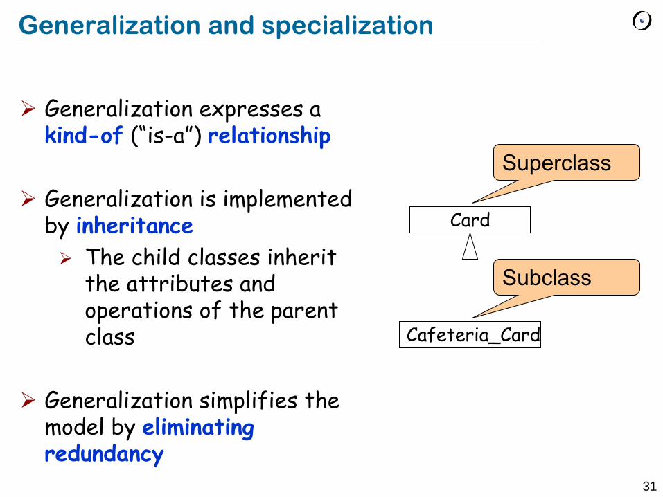
Generalization expresses a kind-of (“is-a”) relationship
Generalization is implemented by inheritance
The child classes inherit the attributes and operations of the parent class
Generalization simplifies the model by eliminating redundancy
Card
Cafeteria_Card
Superclass
Subclass

32
Associations
A line between two classes denotes an association
An association is a type of relation between classes
Objects of the classes can communicate using the association, e.g.
Class A has an attribute of type B
Class A creates instances of B
Class A receives a message with argument of type B
Class A Class B uses
Optional name Optional reading
direction
Role A Role B
Multiplicity Multiplicity
Optional role Optional multiplicity

33
Association multiplicity
Multiplicity denotes how many objects of the class take part in the relation
1-to-1
1-to-many
many-to-many
City Country 1 1 is capital of
Mother Child 1..*
Person Company works for * *

34
Association roles
Different instances of an class can be differentiate using roles
Example: Invoice and shipping address are both addresses
Example: Position hierarchy
Order Address
Invoice add.
Shipping add.
Invoice address for
Shipping address for
0..1
1
Position
subordination
*
0..1 chief
subordinate

35
Special associations
Aggregation – “part-of” relation between objects
Component can be part of multiple aggregates
Component can be created and destroyed independently of the aggregate
Composition – strong aggregation
A component can only be part of a single aggregate
Exists only together with the aggregate
Curriculum Course *
TicketMachine ZoneButton 3
Aggregate Component

36
More on associations
Ordering of an end – whether the objects at this end are ordered
Changeability of an end – whether the set of objects at this end can be changed after creation
Polygon Point 3..*
{ordered} {frozen, ordered}

37
Navigability of association
Associations can be directed
Direction denotes whether objects can be accessed through this association
Card Card_Reader
Card Card_Reader
Card Card_Reader
Card knows about Card_Reader
Card_Reader knows about Card
Card and Card_Reader know about each other

38
Class diagram for the case study
ETH_Card id
Cafeteria_Card amount read() write()
Pay_Automaton
Pay_Desk input_food() compare()
Display show_Amount() show_Error()
Card_Reader card_insert() card_Amount()
Money_Slot money_In() money_Out() validate_Bill()
1 1
1
1 1 1
1 1
1 1
1
1
1
1

39
Diagrams in UML

40
UML Object diagrams
An Object diagram is used to denote a snapshot of the system at runtime
It shows the existing objects, their attribute values and relations at that particular point of time
42: Cafeteria_Card
id=235813 amount=25.50
pd1: Pay_Desk
Link: name or role-name are optinal
Object identifier

41
Diagrams in UML
42
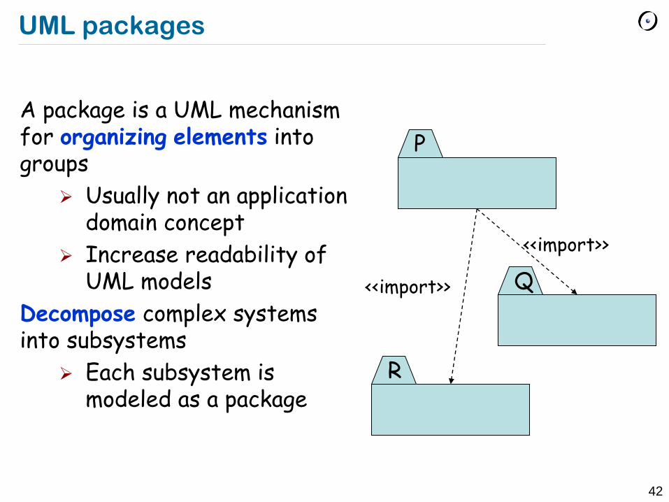
UML packages
A package is a UML mechanism for organizing elements into groups
Usually not an application domain concept
Increase readability of UML models
Decompose complex systems into subsystems
Each subsystem is modeled as a package
R
Q
P
<<import>>
<<import>>

43
Diagrams in UML

44
Component diagrams
Entities:
components • programs • documents • files • libraries • DB tables
interfaces
classes
objects
Relations:
dependency
association (composition)
implementation
<<component>>
DataBase
<<component>>
Business
ODBC
<<component>>
Business
<<provided interfaces>> Interface_m
<<required interfaces>> Inteface_n
<<realization>> Class_A Class_B
<<artifact>> library.jar

45
Diagrams in UML
46
Overview
We will now look at two more diagrams which are used to model the behavior of a system.
Sequence diagrams: used to describe the interaction of objects and show their “communication protocol”
State diagrams: focus on the state of an object (or system) an how it changes due to events

47
Sequence diagrams
:Client :Card_Reader
insertCard( )
insertPIN( )
Time
Entities:
objects (including instances of actors)
Relations:
message passing
Sugar:
lifelines
activations
creations
destructions
frames
Actors and objects: columns
Lifeline: dashed line
Activations: narrow rectangles
Messages: arrows

48
Nested messages
The source of an arrow indicates the activation which sent the message
An activation is as long as all nested activations
:Client :C_Reader
insertCard( )
:ClientData
check( data )
ok / nok
:Display
displayMessage( text )
Data flow

49
Creation and destruction
Creation is denoted by a message arrow pointing to the object In garbage collection environments, destruction can be used to denote the end of the useful life of an object
:Terminal
:Session
start( )
Destruction
log( )
close( )
Creation

50
From Use Cases to Sequence diagrams
Sequence diagrams are derived from flows of events of use cases
An event always has a sender and a receiver
Find the objects for each event
Relation to object identification
Objects/classes have already been identified during object modeling
Additional objects are identified as a result of dynamic modeling
51
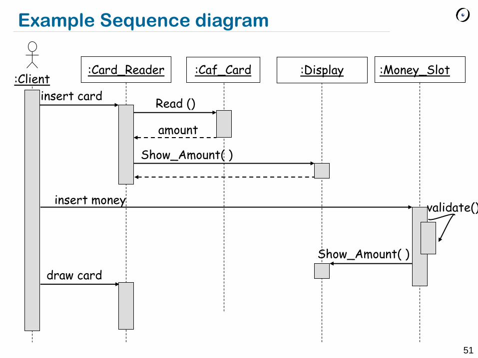
:Money_Slot :Client
:Card_Reader
insert card
:Caf_Card
Read ()
:Display
Show_Amount( )
draw card
amount
Example Sequence diagram
insert money validate()
Show_Amount( )
52
Example Sequence diagram
The diagram shows only the successful case
Exceptional case could go either on another diagram or could be incorporated to this one
Sequence diagrams show main scenario and “interesting” cases
interesting: exceptional or important variant behavior
Need not draw diagram for every possible case
would lead to too many diagrams

53
Interaction frames
:Item :Container :Processor
process()
increase()
loop
[for each item]
decrease()
alt
[value < 100]
[else]

54
Fork structure
The dynamic behavior is placed in a single object, usually a control object
It knows all the other objects and often uses them for direct queries and commands
<<Control>>

55
Stair structure
The dynamic behavior is distributed Each object delegates some responsibility to other
objects Each object knows only a few of the other objects
and knows which objects can help with a specific behavior

56
Fork or stair?
Object-oriented supporters claim that the stair structure is better
The more the responsibility is spread out, the better
Choose the stair (decentralized control) if
The operations have a strong connection
The operations will always be performed in the same order
Choose the fork (centralized control) if
The operations can change order
New operations are expected to be added as a result of new requirements

57
Diagrams in UML

58
State Machine Diagrams
UML State Machine Diagrams are a powerful notation to model finite automata
It shows the states which an object or a (sub)system – depending on the level of abstraction – can have at runtime
It also shows the events which trigger a change of state
59
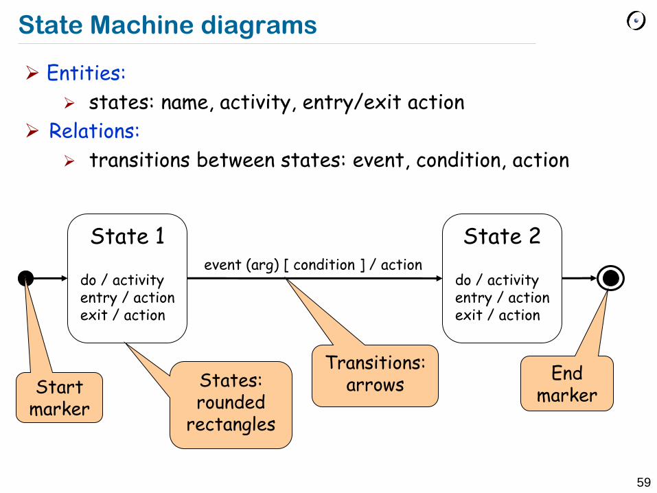
State Machine diagrams
Entities:
states: name, activity, entry/exit action
Relations:
transitions between states: event, condition, action
State 1 do / activity entry / action exit / action
State 2 do / activity entry / action exit / action
event (arg) [ condition ] / action
States: rounded
rectangles
Transitions: arrows Start
marker
End marker

60
State Machine diagram for the case study
Request money do / increase amount entry / validate money
Card check
Remember: event (arg) [ condition ] / action
Ready
Load card
/ return_card
[Card = !OK ] / return_card
Insert_Card
[ Card = OK ]
Cancel/ return_card
Insert_Money Done

61
Composite/nested State Machine diagrams
Activities in states can be composite items that denote other state diagrams
Sets of substates in a nested state diagram can be denoted with a superstate
Avoid spaghetti models
Reduce the number of lines in a state diagram

62
State diagrams: example composite state
Off
On
Working
Blinking
Red Yellow
Yellow Green
Red Green
TurnOn
TurnOff
SwitchOn
SwitchOff
after 3 sec
after 45 sec after 5 sec
after 30 sec
TrafficLight
63
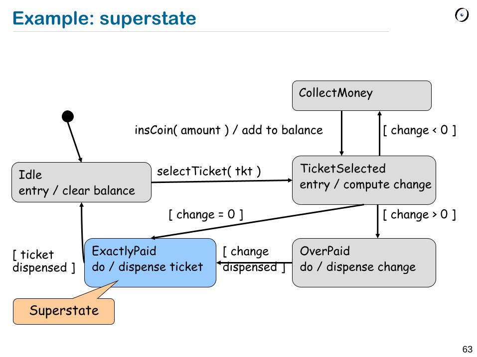
Example: superstate
Idle entry / clear balance
CollectMoney
TicketSelected entry / compute change
ExactlyPaid do / dispense ticket
OverPaid do / dispense change
insCoin( amount ) / add to balance
selectTicket( tkt )
[ change > 0 ] [ change = 0 ]
[ change < 0 ]
[ change dispensed ]
[ ticket dispensed ]
Superstate
64
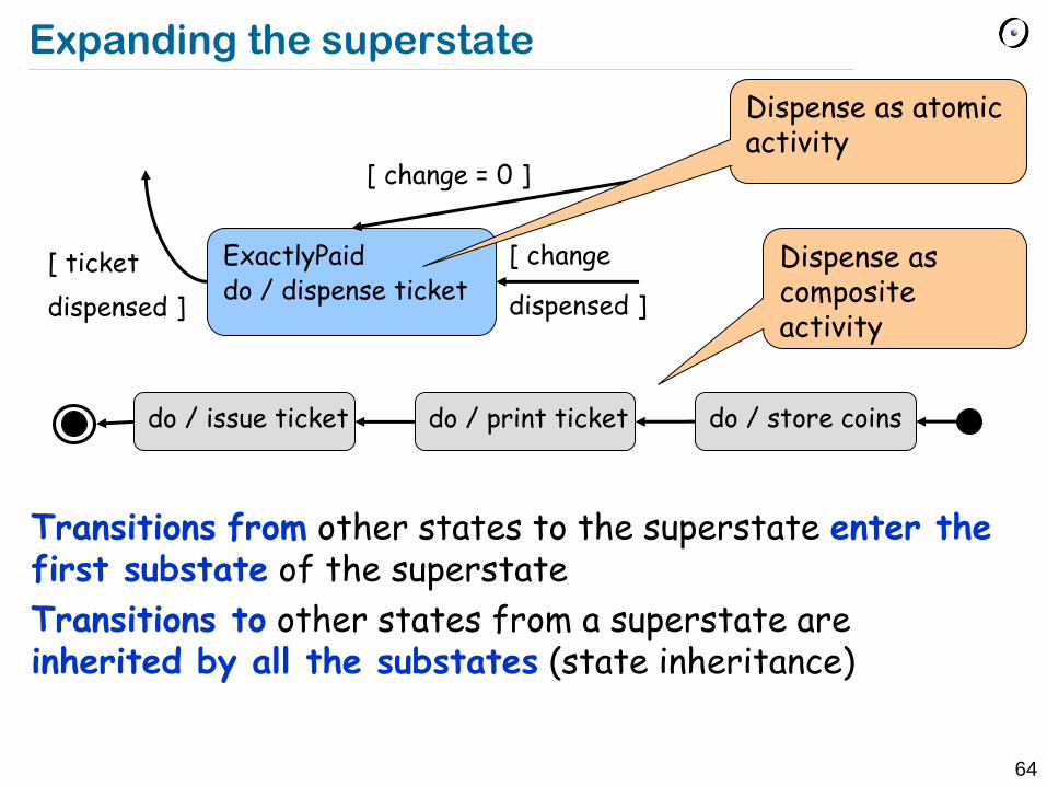
Expanding the superstate
Transitions from other states to the superstate enter the first substate of the superstate
Transitions to other states from a superstate are inherited by all the substates (state inheritance)
do / store coins do / issue ticket do / print ticket
ExactlyPaid do / dispense ticket
[ change = 0 ]
[ change
dispensed ]
[ ticket
dispensed ]
Dispense as atomic activity
Dispense as composite activity
65
State diagram vs. Sequence diagram
State diagrams help to identify
Changes to an individual object over time
Sequence diagrams help to identify
The temporal relationship between objects
Sequence of operations as a response to one or more events
66
Diagrams in UML

67
Practical tips
Create component diagrams only for large, distributed systems
Create state diagrams only for classes with complex, interesting behavior (usually classes representing entities from the problem domain or performing control)
Create activity diagrams for complex algorithms and business processes (not for every operation)
Create sequence diagrams for nontrivial collaborations and protocols (not for every scenario)
Don‟t put too much information on a diagram
Choose the level of abstraction and maintain it