software architecture chapter 2: architectural patterns
DESCRIPTION
Software Architecture Chapter 2: Architectural Patterns. Feng Zhiyong Tianjin University Apr. 5, 2007. Interactive Systems. The Model-View-Controller pattern (MVC) divides an interactive application into three components. The model contains the core functionality and data. - PowerPoint PPT PresentationTRANSCRIPT

Software Architecture Chapter 2: Architectural Patterns
Feng Zhiyong
Tianjin University
Apr. 5, 2007
Interactive Systems
The Model-View-Controller pattern (MVC) divides an interactive application into three components.
– The model contains the core functionality and data. – Views display information to the user. – Controllers handle user input. – Views and controllers together comprise the user interface. A change-
propagation mechanism ensures consistency between the user interface and the model.
The Presentation-Abstraction-Control pattern (PAC) defines a structure for interactive software systems in the form of a hierarchy of cooperating agents. Every agent is responsible for a specific aspect of the application's functionality and consists of three components:
– presentation, abstraction, and control. This subdivision separates the human-computer interaction aspects of the agent from its functional core and its communication with other agents.

Model-View-Controller
The Model-View-Controller architectural pattern (MVC) divides an interactive application into three components.
– The model contains the core functionality and data. – Views display information to the user.– Controllers handle user input.
Views and controllers together comprise the user interface. A change-propagation mechanism ensures consistency between the user interface and the model.

Example
Context: Interactive applications with a flexible human-computer interface.

Problem
The same information is presented differently in different windows, for example, in a bar or pie chart.
The display and behavior of the application must reflect data manipulations immediately.
Changes to the user interface should be easy, and even possible at run-time.
Supporting different 'look and feel' standards or porting the user interface should not affect code in the core of the application.
Solution
MVC divides an interactive application into the three areas: processing, output, and input.
The model component encapsulates core data and functionality. The model is independent of specific output representations or input behavior.
View components display information to the user. A view obtains the data from the model. There can be multiple views of the model.
Each view has an associated controller component. Controllers receive input, usually as events that encode mouse movement, activation of mouse buttons, or keyboard input. Events are translated to service requests for the model or the view. The user interacts with the system solely through controllers.

Structure
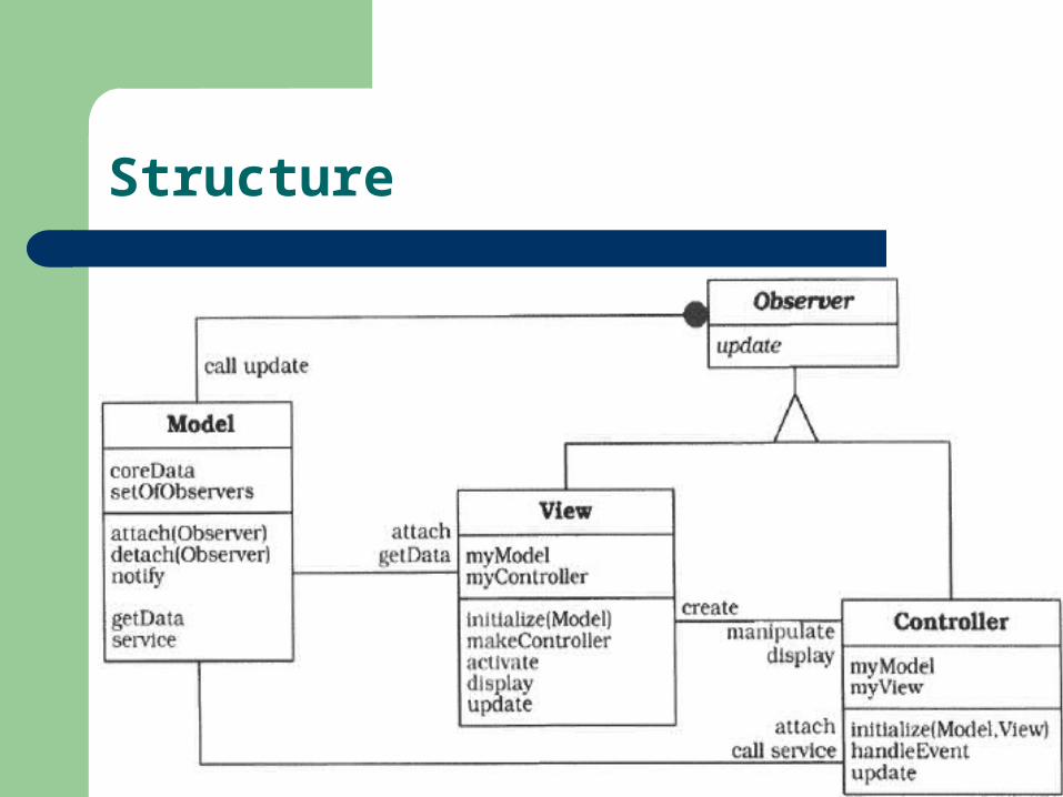
Structure
Dynamics----Scenario I
The controller accepts user input in its event-handling procedure, interprets the event, and activates a service procedure of the model.
The model performs the requested service. This results in a change to its internal data.
The model notifies all views and controllers registered with the change-propagation mechanism of the change by calling their update procedures.
Each view requests the changed data from the model and redisplays itself on the screen.
Each registered controller retrieves data from the model to enable or disable certain user functions. For example, enabling the menu entry for saving data can be a consequence of modifications to the data of the model.
The original controller regains control and returns from its event-handling procedure.

Dynamics----Scenario I

Dynamics----Scenario II
The model instance is created, which then initializes its internal data structures.
A view object is created. This takes a reference to the model as a parameter for its initialization.
The view subscribes to the change-propagation mechanism of the model by calling the attach procedure.
The view continues initialization by creating its controller. It passes references both to the model and to itself to the controller's initialization procedure.
The controller also subscribes to the change-propagation mechanism by calling the attach procedure.
After initialization, the application begins to process events.

Dynamics----Scenario II

Implementation
Separate human-computer interaction from core functionality.

Implementation
Implement the change-propagation mechanism

Implementation
Design and implement the views.

Implementation
Design and implement the controllers.

Implementation
Design and implement the view-controller relationship.

Implementation
Implement the set-up of MVC.

Implementation
Dynamic view creation
– Apply the View Handler design pattern to implement this view management component.
'Pluggable controllers.
Implementation
Infrastructure for hierarchical views and controllers.
Further decoupling from system dependencies.

Variants
Document-View

Known Uses
Smalltalk MFC ET++

Consequences ---- benefits
Multiple views of the same model. Synchronized views. 'Pluggable' views and controllers. Exchangeability of 'look and feel'. Framework potential.
Consequences ---- liabilities
Increased complexity. Potential for excessive number of updates. Intimate connection between view and controller. Close coupling of views and controllers to a model. Inefficiency of data access in view. Inevitability of change to view and controller
when porting. Difficulty of using MVC with modern user-
interface took.

Presentation-Abstraction-Control
The Presentation-Abstraction-Control architectural pattern (PAC) defines a structure for interactive software systems in the form of a hierarchy of cooperating agents. Every agent is responsible for a specific aspect of the application's functionality and consists of three components: presentation, abstraction, and control. This subdivision separates the human-computer interaction aspects of the agent from its functional core and its communication with other agents.

Example
Context Development of an interactive application with the help of agents.
Problem
Agents often maintain their own state and data.
Interactive agents provide their own user interface, since their respective human-computer interactions often differ widely.
Systems evolve over time.

Solution

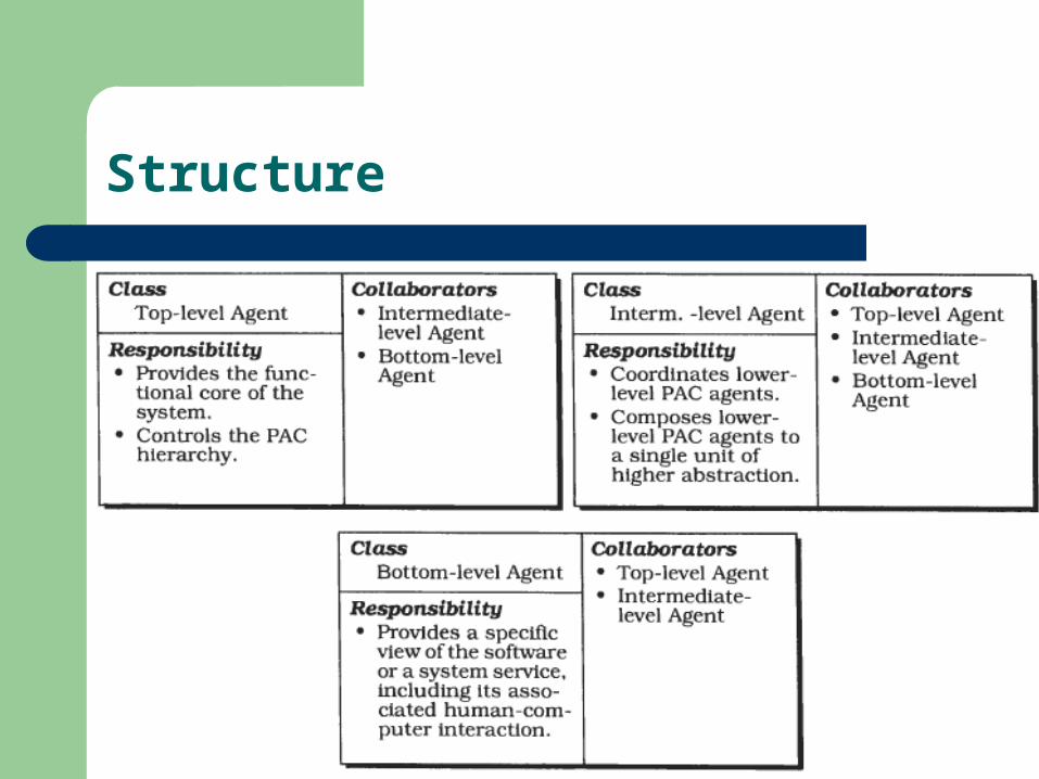
Structure
The main responsibility of the top-lewl PAC agent is to provide the global data model of the software.
– It allows lower-level agents to make use of the services of the top-level agents, mostly to access and manipulate the global data model. Incoming service requests from lower-level agents are forwarded either to the abstraction component or the presentation component.
– It coordinates the hierarchy of PAC agents. It maintains information about connections between the top-level agent and lower-level agents. The control component uses this information to ensure correct collaboration and data exchange between the top –level agent and lower-level agents.
– It maintains information about the interaction of the user with the system. For example, it may check whether a particular operation can be performed on the data model when triggered by the user. It may also keep track of the functions called to provide history or undo/redo services for operations on the functional core.
Structure
Bottom-level PAC agents represent a specific semantic concept of the application domain
– The presentation component of a bottom-level PAC agent presents a specific view of the corresponding semantic concept, and provides access to all the functions users can apply to it.
– The abstraction component of a bottom-level PAC agent has a similar responsibility as the abstraction component of the top-level PAC agent, maintaining agent-specific data.
– The control component of a bottom-level PAC agent maintains consistency between the abstraction and presentation components, thereby avoiding direct dependencies between them.
– The control component of bottom-level PAC agents communicates with higher-level agents to exchange events and data.
Structure

Structure
Structure
Dynamics----Scenario I
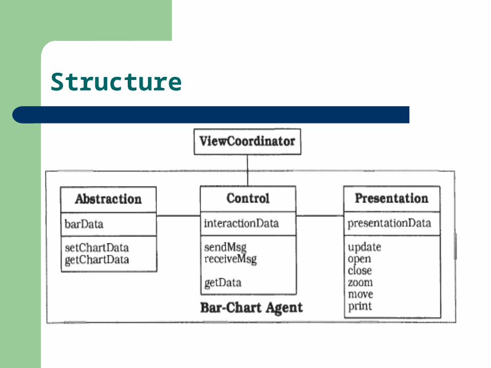
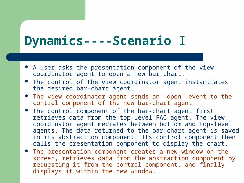
A user asks the presentation component of the view coordinator agent to open a new bar chart.
The control of the view coordinator agent instantiates the desired bar-chart agent.
The view coordinator agent sends an 'open' event to the control component of the new bar-chart agent.
The control component of the bar-chart agent first retrieves data from the top-level PAC agent. The view coordinator agent mediates between bottom and top-level agents. The data returned to the bar-chart agent is saved in its abstraction component. Its control component then calls the presentation component to display the chart.
The presentation component creates a new window on the screen, retrieves data from the abstraction component by requesting it from the control component, and finally displays it within the new window.

Dynamics----Scenario I

Dynamics----Scenario II
The user enters new data into a spreadsheet. The control component of the spreadsheet agent forwards this data to the top-level PAC agent.
The control component of the top-level PAC agent receives the data and tells the top-level abstraction to change the data repository accordingly. The abstraction component of the top-level agent asks its control component to update all agents that depend on the new data. The control component of the top-level PAC agent therefore notifies the view coordinator agent.
The control component of the view coordinator agent forwards the change notification to all view PAC agents it is responsible for coordinating.
As in the previous scenario, all view PAC agents then update their data and refresh the image they display.

Dynamics----Scenario II
Implementation
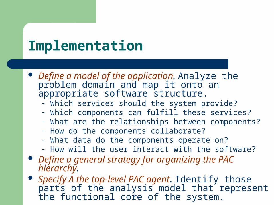
Define a model of the application. Analyze the problem domain and map it onto an appropriate software structure.
– Which services should the system provide?– Which components can fulfill these services?– What are the relationships between components?– How do the components collaborate?– What data do the components operate on?– How will the user interact with the software?
Define a general strategy for organizing the PAC hierarchy.
Specify A the top-level PAC agent. Identify those parts of the analysis model that represent the functional core of the system.

Implementation
Specify the bottom-level PAC agents. Identify those components of the analysis model that represent the smallest self-contained units of the system on which the user can perform operations or view presentations.
Specify bottom-level PAC agents for system services. Often an application includes additional services that are not directly related to its primary subject.
Specify intermediate-level PAC agents to compose lower-level PAC agents. Often, several lower-level agents together form a higher-level semantic concept on which users can operate.
Specify intermediate-level PAC agents to coordinate lower-level PAC agents. Many systems offer multiple views of the same semantic concept.
Implementation
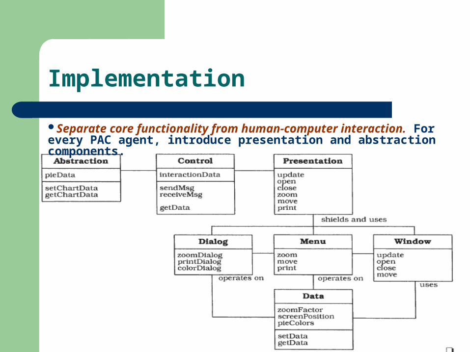
Separate core functionality from human-computer interaction. For every PAC agent, introduce presentation and abstraction components.
Implementation
Provide the external interface.– One way of implementing communication with other agents
is to apply the Composite Message pattern– A second option is to provide a public interface that offers
every service of an agent as a separate function.– A PAC agent can be connected to other PAC agents in a
flexible and dynamic way by using registration functionality, as introduced by the Publisher-Subscriber pattern.
– If a PAC agent depends on data or information maintained by other PAC agents, you should provide a change-propagation mechanism. Such a mechanism should involve all agents and all levels of the hierarchy and work in both directions.

Implementation
Link the hierarchy together.– After implementing the individual PAC agents you can build the
final PAC hierarchy. Connect every PAC agent with those lower-level PAC agents with which it directly cooperates.
– Provide the PAC agents that dynamically create and delete lower-level PAC agents with functionality to dynamically extend or reduce the PAC hierarchy. For example, the view coordinator agent in our information system creates a new view PAC agent if the user wants to open a particular view, and deletes this agent when the user closes the window in which the view is displayed.

Variants
PAC agents as active objects. Many applications, especially interactive ones, benefit from multi-threading. The mobile robot system is an example of a multi-threaded PAC architecture. Every PAC agent can be implemented as an active object that lives in its own thread of control. Design patterns like Active Object and Half-Sync/Half-Async can help you implement such an architecture.
PAC agents as processes. To support PAC agents located in different processes or on remote machines, use proxies to locally represent these PAC agents and to avoid direct dependencies on their physical location. Use the Forwarder-Receiver pattern) or the Client-Dispatcher-Server pattern (323) to implement the inter-process communication (IPC) between PAC agents.
Known Uses
Network Traffic Management.– Gathering traffic data from switching units.– Threshold checking and generation of overflow exceptions.– Logging and routing of network exceptions.– Visualization of traffic flow and network exceptions.– Displaying various user-configurable views of the whole
network.– Statistical evaluations of traffic data.– Access to historic traffic data.– System administration and configuration.

Network Traffic Management
Known Uses
Mobile Robot.– Provide the robot with a description of the
environment it will work– in, places in this environment, and routes
between places.– Subsequently modify the environment.– Specify missions for the robot.– Control the execution of missions.– Observe the progress of missions.

Mobile Robot

Consequences-benefits
Separation of concerns. Support for change and extension. Support for multi-tasking.

Consequences-liabilities
Increased system complexity. Complex control component. Efficiency. The overhead in the communication
between PAC agents may impact system efficiency. Applicability. The smaller the atomic semantic
concepts of an application are, and the greater the similarity of their user interfaces, the less applicable this pattern is.

Adaptable Systems
Systems evolve over time-new functionality is added and existing services are changed.
– The Microkernel pattern applies to software systems that must be able to adapt to changing system requirements. It separates a minimal functional core from extended functionality and customer-specific parts. The microkernel also serves as a socket for plugging in such extensions and coordinating their collaboration.
– The Reflection pattern provides a mechanism for changing structure and behavior of software systems dynamically. It supports the modification of fundamental aspects, such as type structures and function call mechanisms. In this pattern, an application is split into two parts. A meta level provides information about selected system properties and makes the software self-aware. A base level includes the application logic. Its implementation builds on the meta level. Changes to information kept in the meta level affect subsequent base-level behavior.
Microkernel
The Microkernel architectural pattern applies to software systems that must be able to adapt to changing system requirements. It separates a minimal functional core from extended functionality and customer-specific parts. The microkernel also serves as a socket for plugging in these extensions and coordinating their collaboration.

Example
The development of several applications that use similarprogramming interfaces that build on the same core functionality.
Problem
Particular consideration– The application platform must cope with continuous hardware
and software evolution.– The application platform should be portable, extensible and
adaptable to allow easy integration of emerging technologies. This leads to the following forces:
– The applications in your domain need to support different, but similar, application platforms.
– The applications may be categorized into groups that use the same functional core in different ways, requiring the underlying application platform to emulate existing standards.
The functional core of the application platform should be separated into a component with minimal memory size, and services that consume as little processing power as possible.

Solution
Encapsulate the fundamental services of your application platform in a microkernel component.
– Core functionality that cannot be implemented within the microkernel without unnecessarily increasing its size or complexity should be separated in internal servers.
– External servers implement their own view of the underlying microkernel.
To construct this view, they use the mechanisms available through the interfaces of the microkernel. Every external server is a separate process that itself represents an application platform. Hence, a Microkernel system may be viewed as an application platform that integrates other application platforms.
– Clients communicate with external servers by using the communication facilities provided by the microkernel.

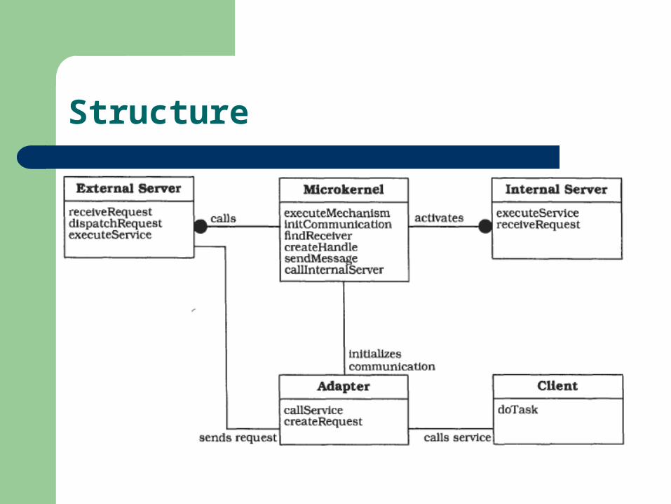
Structure
Internal servers External servers Adapters Clients Microkernel

Structure
Structure

Dynamics----Scenario I
At a certain point in its control flow the client requests a service from an external server by calling the adapter.
The adapter constructs a request and asks the microkernel for a communication link with the external server.
The microkernel determines the physical address of the external server and returns it to the adapter.
After retrieving this information, the adapter establishes a direct communication link to the external server.
The adapter sends the request to the external server using a remote procedure call.
The external server receives the request, unpacks the message and delegates the task to one of its own methods. After completing the requested service, the external server sends all results and status information back to the adapter.
The adapter returns to the client, which in turn continues with its control flow.

Dynamics----Scenario I

Dynamics----Scenario II
The external server sends a service request to the microkernel.
A procedure of the programming interface of the microkernel is called to handle the service request. During method execution the microkernel sends a request to an internal server.
After receiving the request, the internal server executes the requested service and sends all results back to the microkernel.
The microkernel returns the results back to the external server.
Finally, the external server retrieves the results and continues with its control flow.

Dynamics----Scenario II

Implementation
1. Analyze the application domain. If you already know the policies your external servers need to offer, or if you have a detailed knowledge about the external servers you are going to implement, continue with step 2. If not, perform a domain analysis and identify the core functionality necessary for implementing external servers, then continue with step 3.
2. Analyze external servers. Analyze the policies external servers are going to provide. You should then be able to identify the functionality you require within your application domain.
3. Categorize the services. Whenever possible, group all the functionality into semantically-independent categories.

Implementation
4. Partition the categories. Separate the categories into services that should be part of the microkernel, and those that should be available as internal servers. You need to establish criteria for this separation.
5. Find a consistent and complete set of operations and abstractions for every category you identified in step 1. Remember that the microkernel provides mechanisms, not policies. Each policy an external server provides must be implemented through use of the services the microkernel offers through its interfaces.– Creating and terminating processes and threads.– Stopping and restarting them.– Reading from or writing to process address spaces.– Catching and handling exceptions.– Managing relationships between processes or threads.– Synchronizing and coordinating threads.

Implementation
Determine strategies for request transmission and retrieval. Specify the facilities the microkernel should provide for communication between components.
– Synchronous Remote Procedure Calls (RPCs). RPCs enable a client to invoke the services of a remote server as if they were implemented by local procedure calls. The mechanisms necessary for supporting RPCs, for example the packing and unpacking of requests or the transmission of messages across process boundaries, are hidden from the caller and the sewer called.
– Asynchronous Mailboxes. A mailbox is a type of message buffer. A set of components is allowed to read messages from the mailbox, another set of components has permission to write messages to it. A component may be allowed to perform both activities.
Implementation
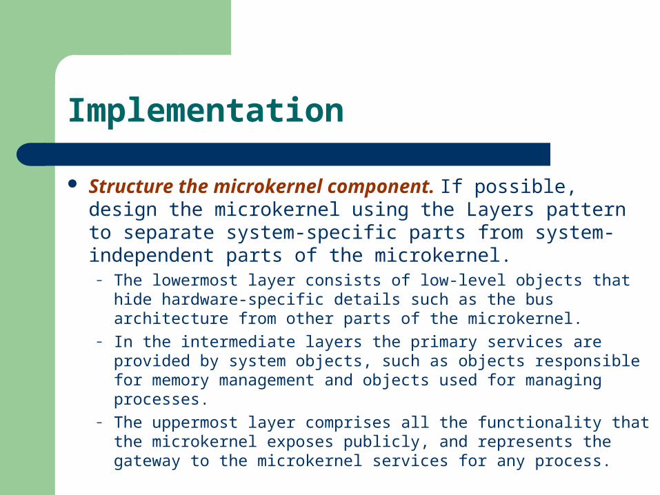
Structure the microkernel component. If possible, design the microkernel using the Layers pattern to separate system-specific parts from system-independent parts of the microkernel.
– The lowermost layer consists of low-level objects that hide hardware-specific details such as the bus architecture from other parts of the microkernel.
– In the intermediate layers the primary services are provided by system objects, such as objects responsible for memory management and objects used for managing processes.
– The uppermost layer comprises all the functionality that the microkernel exposes publicly, and represents the gateway to the microkernel services for any process.

Implementation
To specify the programming interfaces of the microkernel, you need to decide how these interfaces should be accessible externally. You must obviously take into account whether the microkernel is implemented as a separate process or as a module that is physically shared by other components.
The microkernel is responsible for managing all system resources such as memory blocks, devices or device contexts-a handle to an output area in a graphical user interface implementation. The microkernel maintains information about resources and allows access to them in a coordinated and systematic way.
Implementation
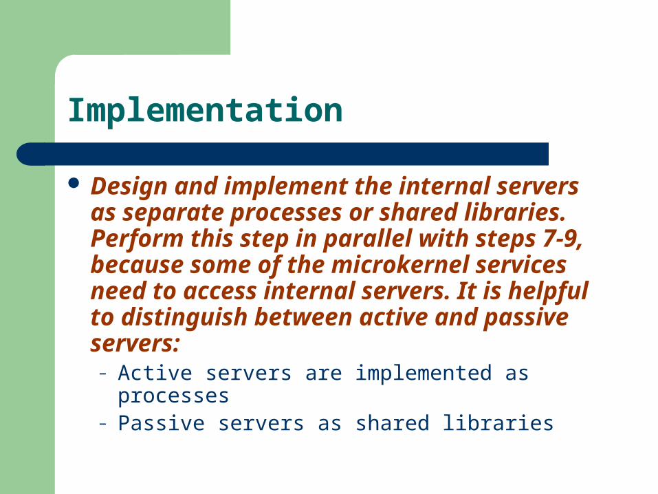
Design and implement the internal servers as separate processes or shared libraries. Perform this step in parallel with steps 7-9, because some of the microkernel services need to access internal servers. It is helpful to distinguish between active and passive servers:– Active servers are implemented as processes– Passive servers as shared libraries

Implementation
Implement the external servers. All the policies the external servers include are based on the services available in the programming interfaces of the microkernel. An external server receives requests, analyzes them, executes the appropriate services and sends the results back to the caller. When executing services, the external server may call operations in the microkernel.
A full implementation of Microsoft’s Win32 and Win16 APIs, to allow users to run Windows NT, Windows 3.11 and Windows 95 applications.
The complete functionality provided by IBM OS/2 Warp 2.0. An implementation of Openstep. All relevant UNIX System V interfaces specified by X/Open. a

Implementation
Implement the adapters. The primary task of an adapter is to provide operations to its clients that are forwarded to an external server.– Whenever the client calls a function of the external
server, the adapter packages all relevant information into a request and forwards the request to the appropriate external server. The adapter then waits for the server’s response and finally returns control to the client, using the facilities for inter-component communication.

Develop client Applicalions or use existing ones for the ready-to-run Microkernel system. When creating a new client for a specific external server, its architecture is only limited by the constraints imposed by the external server. That is, clients depend on the policies implemented by their external server.
– In Hydra we can develop Microsoft Windows applications by accessing the services of the Microsoft Windows external server via the Microsoft Windows adapter.

Example resolved
Building an external server on top of the Hydra microkernel that implements all the programming interfaces provided by MacOS, including the policies of the Macintosh user interface.
Providing an adapter that is designed as a library, dynamically linked to clients. For every API function available in a native MacOS system, a syntactically-identical procedure must be provided by the library.
Implementing the internal sewers required for MacOS. For example, one internal server provides the network protocol AppleTalk. The microkernel must be modified to invoke these additional internal servers on behalf of the MacOS server.

Variants
Microkernel System with indirect Client-Server connections.
Distributed Microkernel System

Known Uses
The Mach operating system The operating system Amoeba Chorus Windows NT Microkernel Datenbank Engine
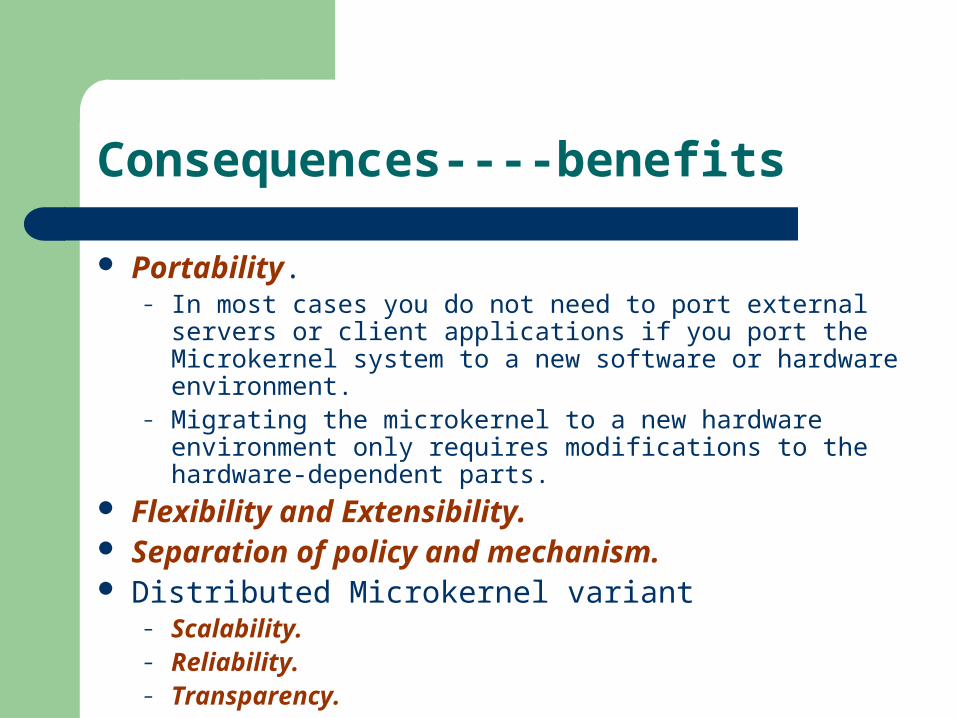
Consequences----benefits
Portability.– In most cases you do not need to port external servers or client
applications if you port the Microkernel system to a new software or hardware environment.
– Migrating the microkernel to a new hardware environment only requires modifications to the hardware-dependent parts.
Flexibility and Extensibility. Separation of policy and mechanism. Distributed Microkernel variant
– Scalability.– Reliability.– Transparency.

Consequences----liabilities
Performance. Complexity of design and implementation.

Reflection
The Reflection architectural pattern provides a mechanism for changing structure and behavior of software systems dynamically. It supports the modification of fundamental aspects. such as type structures and function call mechanisms. In this pattern, an application is split into two parts.
– A meta level provides information about selected system properties and makes the software self-aware.
– A base level includes the application logic. Its implementation builds on the meta level. Changes to information kept in the meta level affect subsequent base-level behavior.
Also Known As Open Implementation, Meta-Level Architecture
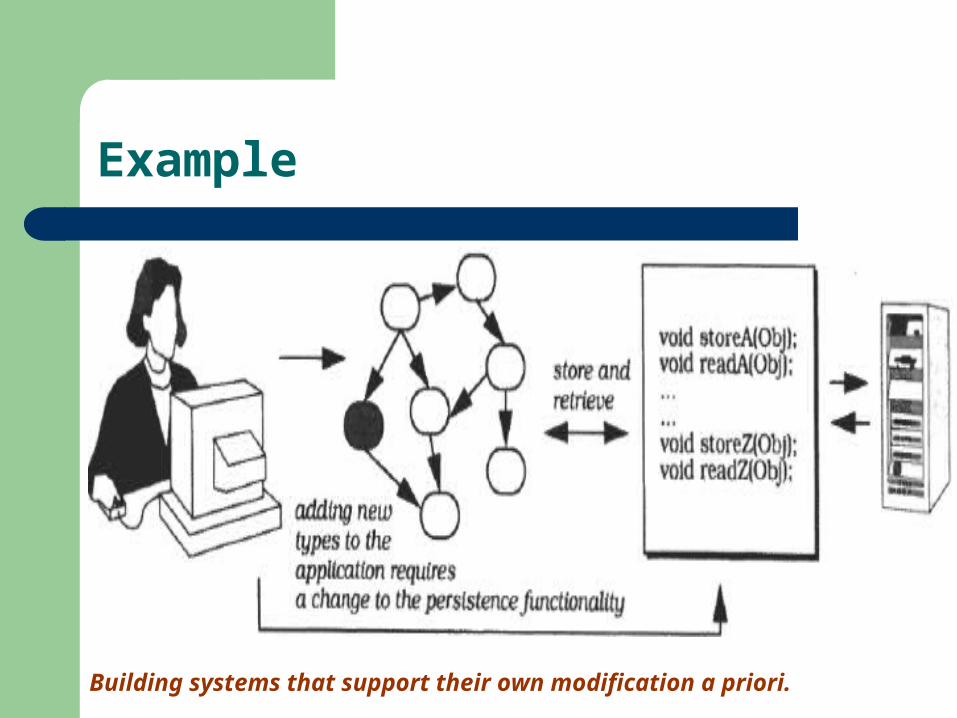
Example
Building systems that support their own modification a priori.

Problem
Changing software is tedious, error prone, and often expensive. Adaptable software systems usually have a complex inner structure. The more techniques that are necessary for keeping a system chang
eable, such as parameterization, subclassing, mix-ins, or even copy and paste, the more awkward and complex its modification becomes. A uniform mechanism that applies to all kinds of changes is easier to use and understand.
Changes can be of any scale, from providing shortcuts for commonly-used commands to adapting an application framework for a specific customer.
Even fundamental aspects of software systems can change, for example the communication mechanisms between components

Solution
The meta level provides a self-representation of the software to give it knowledge of its own structure and behavior, and consists of so-called rnetaobjects.
The base level defines the application logic. Its implementation uses the metaobjects to remain independent of those aspects that are likely to change.
An interface is specified for manipulating the metaobjects. It is called the metaobject protocol (MOP), and allows clients to specify particular changes, such as modification of the function call mechanism metaobject mentioned above.

Structure
The meta level– It can be provided by the run-time environment of the system, such as C
++ type identification objects.– It can be user-defined, such as the function call mechanism in the previo
us section.– It can be retrieved from the base level at run-time, for example informatio
n about the current state of computation. The base level
– models and implements the application logic of the software. Its components represent the various services the system offers as well as their underlying data model.
– uses the information and services provided by the metaobjects, such as location information about components and function call mechanisms.
The metaobject protocol (MOP] serves as an external interface to the meta level, and makes the implementation of a reflective system accessible in a defined way.

Structure

Structure

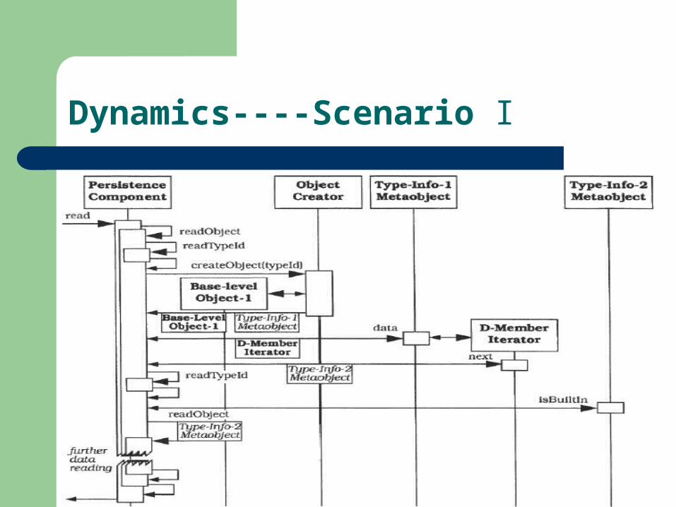
Dynamics----Scenario I
The user wants to read stored objects. The request is forwarded to the read() procedure of the persistence component, together with the name of the data file in which the objects are stored.
Procedure read() opens the data file and calls an internal readobject() procedure which reads the first type identifier.
Procedure readObject() calls the metaobject that is responsible for the creation of objects. The 'object creator' metaobject instantiates an 'empty' object of the previously-determined type. It returns a handle to this object and a handle to the corresponding run-time type information (RTTI) metaobject.

Dynamics----Scenario I
Procedure readobject() requests an iterator over the data members of the object to be read from its corresponding metaobject. The procedure iterates over the data members of the object.
Procedure readobject() reads the type identifier for the next data member. If the type identifier denotes a built-in type--a case we do not illustrate--the readobject() procedure directly assigns the next data item from the file to the data member, based on the data member's size and offset within the object. Othenvise readobject() is called recursively. This recursion starts with the creation of an 'empty' object if the data member is a pointer. If not, the recursively called readobject() operates on the existing layout of the object that contains the data member.
After reading the data, the read() procedure closes the data file and returns the new objects to the client that requested them.
Dynamics----Scenario I

Dynamics----Scenario II
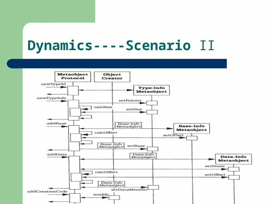
A client invokes the metaobject protocol to specify run-time type information for a new type in the application. The name of the type is passed as an argument.
The metaobject protocol creates a metaobject of class type-info for this type. This metaobject also serves as a type identifier.
The client calls the metaobject protocol to add extended type information. This includes setting the size of the type, whether or not it is a pointer, and its inheritance relationships to other types. To handle the inheritance relationship, the metaobject protocol creates metaobjects of class baseInfo. These maintain a handle to the type-info object for a particular base class and its offset within the new type.
In the next step, the client specifies the inner structure for the new type. The metaobject protocol is provided with the name and type of every data member. For every data member the metaobject protocol creates an object of class dataInfo. It maintains a handle to the type-info object for the type of the member, its name, and whether or not it is a static data member. The dataInfo object also maintains the absolute address of the data member if it is static, otherwise its offset within the new type.
Dynamics----Scenario II
The client invokes the metaobject protocol to modify existing types that include the new type as a data member. Appropriate data member information is added for every type. Since this step is very similar to the previous one, we do not illustrate it in the object message sequence chart that follows.
Finally, the client calls the metaobject protocol to adapt the 'object creator' metaobject. The persistence component must be able to instantiate an object of the new type when reading persistent data.
The metaobject protocol automatically generates code for creating objects of the new type, based on the prevlously-added type information. It further integrates the new code with the existing implementation of the 'object creator' metaobject, compiles the modified implementation, and links it with the application.
Dynamics----Scenario II

Implementation
Define a model of the application. Analyze the problem domain and decompose it into an appropriate software structure. Answer the following questions:– Which services should the software provide?– Which components can fulfil these services?– What are the relationships between the components?– How do the components cooperate or collaborate?– What data do the components operate on?– How will the user interact with the software?

Implementation
Identify varying behavior. Analyze the model developed in the previous step and determine which of the application services may vary and which remain stable.
– Real-time constraints, such as deadlines, time-fence protocols and algorithms for detecting deadline misses.
– Transaction protocols, for example optimistic and pessimistic transaction control in accounting systems.
– Inter-process communication mechanisms, such as remote procedure calls and shared memory.
– Behavior in case of exceptions, for example the handling of deadline misses in real-time systems.
– Algorithms for application services, such as country specific VAT calculation.

Implementation
Identify structural aspects of the system, which, when changed, should not affect the implementation of the base level.
Identify system services that support both the variation of application services identified in step 2 and the independence of structural details identified in step 3.– Resource allocation– Garbage collection– Page swapping– Object creation
Implementation
Define the metaobjects. For every aspect identifled in the three previous steps, define appropriate metaobjects. Encapsulating behavior is supported by several domain-independent design patterns, such as Objectifier. Strategy. Bridge, Visitor, and Abstract Factory

Implementation
Define the metaobject protocol. Support a defined and controlled modification and extension of the meta level, and also a modification of relationships between base-level components and metaobjects.– Integrate it with the metaobjects. Every metaobject pro
vides those functions of the metaobject protocol that operate on it.
– Implement the metaobject protocol as a separate component.

Implementation
Define the base level. Implement the functional core and user interface of the system according to the analysis model developed in step 1.
Variants
Refection with several meta levels.– Sometimes metaobjects depend on each other. For ex
ample, consider the persistence component. Changes to the run-time type information of a particular type requires that you update the 'object creator' metaobject. To coordinate such changes you may introduce separate metaobjects, and-conceptually-a meta level for the meta level, or in other words, a meta meta level. In theory this leads to an infinite tower of reflection.
Known Uses
CLOS– The system first determines the methods that are
applicable to a given invocation.– It then sorts the applicable methods in decreasing
order of precedence.– The system finally sequences the execution of the list
of applicable methods. Note that in CLOS more than one method can be executed in response to a given invocation.
Known Uses
MIP– The first layer includes information and functionality that allows software to identi
fy and compare types. This layer corresponds to the standard run-time type identification facilities for C++.
– The second layer provides more detailed information about the type system of an application. For example, clients can obtain information about inheritance relationships for classes, or about their data and function members. This information can be used to browse type structures.
– The third layer provides information about relative addresses of data members, and offers functions for creating 'empty' objects of user-defined types. In combination with the second layer, this layer supports object I/O.
– The fourth layer provides full type information, such as that about friends of a class, protection of data members, or argument and return types of function members. This layer supports the development of flexible inter-process communication mechanisms, or of tools such as inspectors, that need very detailed information about the type structure of an application. The metaobject protocol of MIP allows you to specify

Known Uses
PGen is a persistence component for C++ that is based on MIP. It allows an application to store and read arbitrary C++ object structures.

Known Uses
NEDIS. Properties for certain attributes of classes, such as their allowed
value ranges. Functions for checking attribute values against their required
properties. NEDIS uses these functions to evaluate user input, for example to validate a date.
Default values for attributes of classes, used to initialize new objects. Functions specifying the behavior of the system in the event of
errors, such as invalid input or unexpected 'null' values of attributes. Country-specific functionality, for example for tax calculation. Information about the 'look and feel' of the software, such as the
layout of input masks or the language to be used in the user interface.

Known Uses
OLE 2.0 provides functionality for exposing and accessing type information about OLE objects and their interfaces.

Consequences----benefits
No explicit modification of source code. You do not need to touch existing code when modifying a reflective system. Instead, you specify a change by calling a function of the metaobject protocol.
Changing a software system is easy. The metaobject protocol provides a safe and uniform mechanism for changing software.
Support for many kinds of change. Metaobjects can encapsulate every aspect of system behavior, state and structure.

Consequences---- liabilities
Modifications at the meta level may cause damage. Even the safest metaobject protocol does not prevent users from specifying incorrect modifications.
Increased number of components. It may happen that a reflective software system includes more metaobjects than base-level components.
Lower efficiency. Reflective software systems are usually slower than non-reflective systems.
Not all potential changes to the software are supported. Not all languages support refection.