soft starter instruction manual - zener.com.au · the smartstart 6000 instruction manual:...
TRANSCRIPT

ZENER VARIDRIVE SOLUTIONS
ZENER SMARTSTART® 6000 Soft Starter Instruction Manual


Instruction Manual: Smartstart® 6000 IMI0042 rev K
Contents Introduction 2 Receiving ……… 2 Handling & Storage ……… 2 Handling on Installation ……… 2 Software ……… 2
The Smartstart® 6000 3 Soft Starter Operation ……… 3 ‘SMART‐TORQ’ Torque Control ……… 3
Installation 4 Mechanical Installation ……… 4 Heat Dissipation & ventilation ……… 4 Mechanical Dimensions ……… 5 Power Wiring ‐ General ……… 6 Semiconductor Fuses ……… 6 Power Wiring – 15A‐80A ……… 7 Power Terminals – 100A and above ……… 8 Power Terminals – 6 wire & CT relocation ……… 10 Control Wiring ……… 13 Communications ……… 15
Programming 16
Local Control Panel/Display ……… 16 Trip Log / Resetting ……… 18 Menu Map ……… 19 1 Setup menu – Display (D01‐D20) ……… 20 2 Setup menu – Motor (M01 – M04) ……… 21 3 Setup menu – Control (C01‐C22) ……… 21 4 Setup menu – Protection (P01‐P73) ……… 23 5 Setup menu – Reset (R01‐R13) ……… 26 6 Setup menu – Input (X10‐X22) ……… 27 7 Setup menu – Output (Y10‐Y52) ……… 27 8 Setup menu – Advanced (A10‐A61) ……… 29 9 Setup menu – Network (N01‐N20) ……… 31 10 Setup menu – Commands ……… 32 11 Setup menu – Starter Diagram ……… 32 12 Setup menu – Network Diagram ……… 33 Relay functions, I/O functions, Alarm & Trip Messages ……... 34‐36 Brake fail Protection ……… 37
Specifications ……… 38
Thermal Protection ……… 39
Unit ratings ……… 40
Shipping/Packaging Details ……… 41
Options ……… 42 Appendix – A – Smart‐Torque / Typical start parameters ……… 44 B ‐ Application Diagrams ……… 46 C – Remote Console Instructions …….. 49 D – Data Logger Option Board ……. 50 E – 6 Wire using internal CT’s ……. 52
Set up Record Sheet ……… 53
Read & familiarise yourself with the warnings detailed on Page 1 of the manual before proceeding.
Read all operating instructions before installing, wiring, operating, servicing or inspecting the Smartstart. Ensure that the instruction manual is made available to the final user of the product as well as all personnel involved in any aspect of installation, adjustment or maintenance.
This symbol identifies the essential parameters forquick setup.
(High Voltage Warning)
(General Warning)
IMPORTANT – Read this first !!
Instruction Manual: Smartstart® 6000 IMI0042 rev K Page 1
Read all operating instructions before installing, wiring, operating, servicing or inspecting the Smartstart®6000. Ensure that the instruction manual is made available to the final user of the product as well as all personnel involved in any aspect of installation, adjustment or maintenance. Your Smartstart
®6000 must be applied and installed by a suitably qualified and experienced electrical tradesperson in accordance with this manual, good engineering practice and all local rules and regulations.
There are hazardous voltages inside the Smartstart®6000 whenever it is connected to an electrical supply. The Smartstart®6000 contains high energy circuits that may be hazardous. Do not operate with the covers removed or the doors of the enclosure in which it is installed open. Do not touch the terminals of the Smartstart®6000 or any associated motor and wiring when it is energised, even if the Smartstart®6000 and motor are stopped. Electric shock may result. Do not modify this equipment electrically, mechanically or otherwise. Modification may create safety hazards as well as voiding the UL listing of models so listed. The Smartstart
®6000 is designed to drive an appropriately rated and otherwise suitable 3 phase induction motor. It is not
suitable for single phase motors or other types of motor or non‐motor load. Use with inappropriate load types may create a safety hazard. Where the Smartstart
®6000 is used as a component part of another product, it is the purchaser's responsibility to ensure that the final product meets all of the necessary safety, EMC, regulatory, operational and other requirements for that product. Requirements for the purchaser's final product may be substantially different to the requirements for stand‐alone inverters. The Smartstart
®6000 is intended for use only in fixed wiring applications. It is not intended for use on a flexible supply cable. Mount the Smartstart
®6000 on a vertical, incombustible surface such as metal or masonry. Do not place combustible or flammable material near the Smartstart®6000. Failure to observe these precautions may create a fire hazard The Smartstart
®6000 is manufactured under strict quality control arrangements, however additional and independent safety equipment must be installed if the application is such that failure of the product may result in personal injury or property damage. Ensure the Smartstart
®6000 is applied in a manner that does not adversely affect the proper operation of other equipment or systems, particularly those that have a safety function. Install emergency stop circuitry that removes power from the Smartstart
®6000 and does not depend on any feature of the product for proper and safe operation. The Smartstart
®6000 has features that may be used to cause an automatic restart in certain circumstances. The overall application (machine etc) must be designed such that automatic restart is not hazardous. Do not install this equipment in locations where mechanical damage to the enclosure is possible. In particular, consider vehicles, vandalism and attack by insects or animals. Severe equipment damage and safety hazards may result. The Smartstart®6000 offers an Essential Services Over‐ride (ESO) mode of operation. This mode of operation intentionally ignores some motor and starter protection. As a result the equipment may operate outside its thermal rating and void any warranty.
Introduction
Instruction Manual: Smartstart® 6000 IMI0042 rev K Page 2
Receiving:Inspect the Smartstart®6000 for any shipping damage. If any damage is found, report it to the carrier immediately. Remove cover of starter and visually check for damage. Do not attempt to operate the Smartstart®6000 if any obvious damage exists or suspect damage has occurred. After the initial inspection, the Smartstart®6000 can be repacked and stored in a clean, dry location until it is required for use.
Handling&Storage:To ensure the starter is protected before installation, handle and store the equipment in its packaging. DO NOT store this equipment in an area where the ambient temperature will fall below ‐20ºC or rise above 70ºC. DO NOT store this equipment in areas that are subject to condensation or corrosive atmosphere. Proper storage is necessary to ensure satisfactory startup and performance.
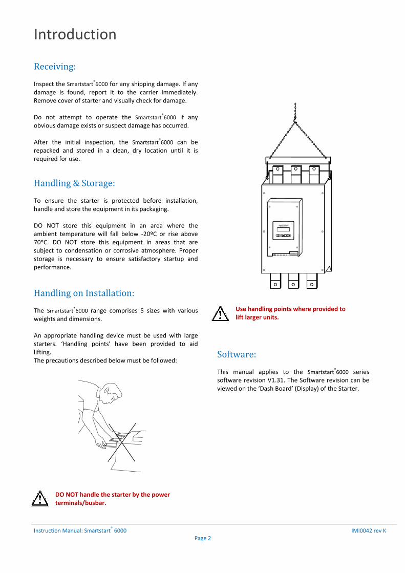
HandlingonInstallation:The Smartstart®6000 range comprises 5 sizes with various weights and dimensions. An appropriate handling device must be used with large starters. ‘Handling points’ have been provided to aid lifting. The precautions described below must be followed:
DO NOT handle the starter by the power terminals/busbar.
Use handling points where provided to lift larger units.
Software:This manual applies to the Smartstart®6000 series software revision V1.31. The Software revision can be viewed on the ‘Dash Board’ (Display) of the Starter.
The Smartstart 6000
Instruction Manual: Smartstart® 6000 IMI0042 rev K Page 3
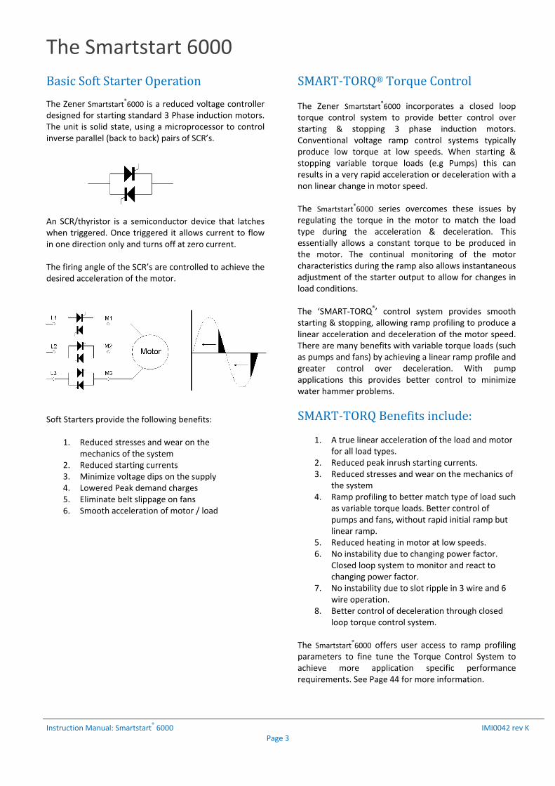
BasicSoftStarterOperationThe Zener Smartstart®6000 is a reduced voltage controller designed for starting standard 3 Phase induction motors. The unit is solid state, using a microprocessor to control inverse parallel (back to back) pairs of SCR’s.
An SCR/thyristor is a semiconductor device that latches when triggered. Once triggered it allows current to flow in one direction only and turns off at zero current. The firing angle of the SCR’s are controlled to achieve the desired acceleration of the motor. Soft Starters provide the following benefits:
1. Reduced stresses and wear on the mechanics of the system
2. Reduced starting currents 3. Minimize voltage dips on the supply 4. Lowered Peak demand charges 5. Eliminate belt slippage on fans 6. Smooth acceleration of motor / load
SMART‐TORQ®TorqueControlThe Zener Smartstart®6000 incorporates a closed loop torque control system to provide better control over starting & stopping 3 phase induction motors. Conventional voltage ramp control systems typically produce low torque at low speeds. When starting & stopping variable torque loads (e.g Pumps) this can results in a very rapid acceleration or deceleration with a non linear change in motor speed. The Smartstart®6000 series overcomes these issues by regulating the torque in the motor to match the load type during the acceleration & deceleration. This essentially allows a constant torque to be produced in the motor. The continual monitoring of the motor characteristics during the ramp also allows instantaneous adjustment of the starter output to allow for changes in load conditions. The ‘SMART‐TORQ®’ control system provides smooth starting & stopping, allowing ramp profiling to produce a linear acceleration and deceleration of the motor speed. There are many benefits with variable torque loads (such as pumps and fans) by achieving a linear ramp profile and greater control over deceleration. With pump applications this provides better control to minimize water hammer problems.
SMART‐TORQBenefitsinclude:
1. A true linear acceleration of the load and motor for all load types.
2. Reduced peak inrush starting currents. 3. Reduced stresses and wear on the mechanics of
the system 4. Ramp profiling to better match type of load such
as variable torque loads. Better control of pumps and fans, without rapid initial ramp but linear ramp.
5. Reduced heating in motor at low speeds. 6. No instability due to changing power factor.
Closed loop system to monitor and react to changing power factor.
7. No instability due to slot ripple in 3 wire and 6 wire operation.
8. Better control of deceleration through closed loop torque control system.
The Smartstart®6000 offers user access to ramp profiling parameters to fine tune the Torque Control System to achieve more application specific performance requirements. See Page 44 for more information.

Installation ‐ Mechanical
Technical Manual: Smartstart® 6000 IMI0042 rev K Page 4
MechanicalInstallationThe Smartstart®6000 should be installed by qualified electrical personnel only. The following should be considered when installing. Mount in a vibration free environment. Mount vertically and away from heat radiating
sources. Do not mount in direct sunlight or on hot surfaces. Mount in a suitable enclosure for the environment
in which it is to operate, the total heat dissipation must be considered.
Do not drill holes into the Smartstart®6000 enclosure.
Do not allow metal shavings or any other conductive material to enter the enclosure or damage may result.
Clearances for airflow:Models: 6R15/30/60/80 Only: Below illustrates the clearances to allow access to Ports if fitted;
i) Remote Console (RJ Connection) ii) SD Card Slot iii) Ethernet Port
HeatDissipationThe Smartstart®6000 is cooled by temperature controlled internal fans. Installing a bypass contactor will reduce the heat dissipated and the ventilation required. Soft Starters generally dissipate approximately 4.5watts per Amp when operated without a bypass contactor. The heat dissipated can be calculated by; Continuous Duty: P = (FLC x 4.5) Bypass Duty: P = (FLC x SC x 4.5 x t x N) / 3600 Where;
P = Power dissipated in Watts FLC = Nameplate FLC of Motor SC = Average starting current expressed per unit of FLC t = Starting time N = Number of starts per hour
When installing the Smartstart®6000 in an enclosure or switch board it is necessary to consider the heat dissipated and then the ventilation required. The following formula’s will assist in determining whether ventilation is required and how much. Ventilated Enclosure: V = (3.1 x P) / T Where; V = Airflow required in m3/hour P = Power dissipated in Watts T = Temperature differential in °C (inside – outside) Non Ventilated Enclosure: A = P / ( T x k) Where; A = Exposed surface area of cabinet (m2) P = Power dissipated in Watts T = Temperature differential (°C) (inside – outside) k = Heat transmission constant (5 for Painted metal)
> 75mm
> 75mm
> 20mm
> 7
5mm
> 7
5mm

Installation ‐ Mechanical
Technical Manual: Smartstart® 6000 IMI0042 rev K Page 5
Dimensions(All Dimensions in mm)
Mounting Holes: Mounting Holes: Mounting Holes:
Model: Chassis A B C D Depth
6R005B2 B2 335 162 315 111 1746R015B2 B2 335 162 315 111 1746R030B2 B2 335 162 315 111 1746R060B2 B3 440 162 420 111 1746R080B2 B3 440 162 420 111 174
Model: Chassis A B C D Depth
6R10000 A2 430 248 400 216 2446R19000 A2 430 248 400 216 2446R22000 A2 430 248 400 216 244
6V09000 A2+ 430 248+55 400 216 244
Model: Chassis A B C D Depth
6R36000 A3 670 375 640 159 2856R58000 A3 670 375 640 159 2856R83000 A3 670 375 640 159 285
6V20000 A3+ 670 375 640 159 3056V40000 A3+ 670 375 640 159 305
Installation ‐ Power Wiring
Technical Manual: Smartstart
® 6000 IMI0042 rev K Page 6
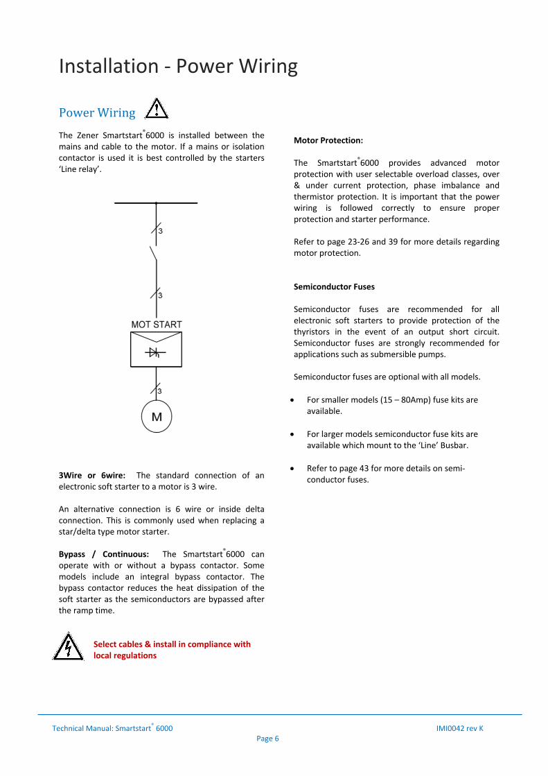
PowerWiringThe Zener Smartstart®6000 is installed between the mains and cable to the motor. If a mains or isolation contactor is used it is best controlled by the starters ‘Line relay’.
3Wire or 6wire: The standard connection of an electronic soft starter to a motor is 3 wire. An alternative connection is 6 wire or inside delta connection. This is commonly used when replacing a star/delta type motor starter. Bypass / Continuous: The Smartstart®6000 can operate with or without a bypass contactor. Some models include an integral bypass contactor. The bypass contactor reduces the heat dissipation of the soft starter as the semiconductors are bypassed after the ramp time.
Select cables & install in compliance with local regulations
Motor Protection: The Smartstart®6000 provides advanced motor protection with user selectable overload classes, over & under current protection, phase imbalance and thermistor protection. It is important that the power wiring is followed correctly to ensure proper protection and starter performance. Refer to page 23‐26 and 39 for more details regarding motor protection. Semiconductor Fuses Semiconductor fuses are recommended for all electronic soft starters to provide protection of the thyristors in the event of an output short circuit. Semiconductor fuses are strongly recommended for applications such as submersible pumps. Semiconductor fuses are optional with all models.
For smaller models (15 – 80Amp) fuse kits are available.
For larger models semiconductor fuse kits are available which mount to the ‘Line’ Busbar.
Refer to page 43 for more details on semi‐conductor fuses.
Installation ‐ Power Terminals (up to 80Amp)
Technical Manual: Smartstart
® 6000 IMI0042 rev K Page 7
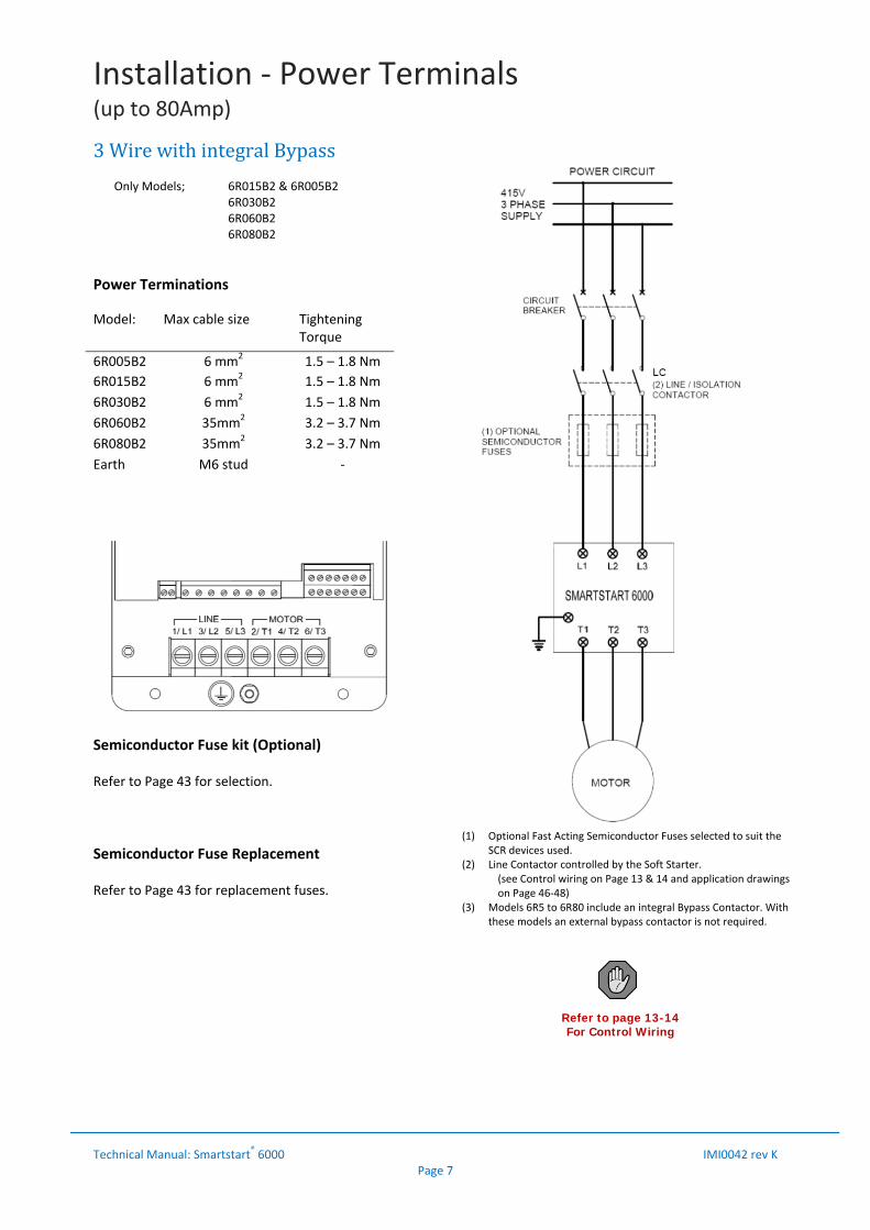
3WirewithintegralBypass Only Models; 6R015B2 & 6R005B2
6R030B2 6R060B2 6R080B2
Power Terminations
Model: Max cable size TighteningTorque
6R005B2 6 mm2 1.5 – 1.8 Nm
6R015B2 6 mm2 1.5 – 1.8 Nm
6R030B2 6 mm2 1.5 – 1.8 Nm
6R060B2 35mm2 3.2 – 3.7 Nm
6R080B2 35mm2 3.2 – 3.7 Nm
Earth M6 stud ‐
Semiconductor Fuse kit (Optional) Refer to Page 43 for selection.
Semiconductor Fuse Replacement Refer to Page 43 for replacement fuses.
Refer to page 13-14 For Control Wiring
(1) Optional Fast Acting Semiconductor Fuses selected to suit the SCR devices used.
(2) Line Contactor controlled by the Soft Starter. (see Control wiring on Page 13 & 14 and application drawings on Page 46‐48)
(3) Models 6R5 to 6R80 include an integral Bypass Contactor. With these models an external bypass contactor is not required.
Installation ‐ Power Terminals (100A model and above)
Technical Manual: Smartstart
® 6000 IMI0042 rev K Page 8
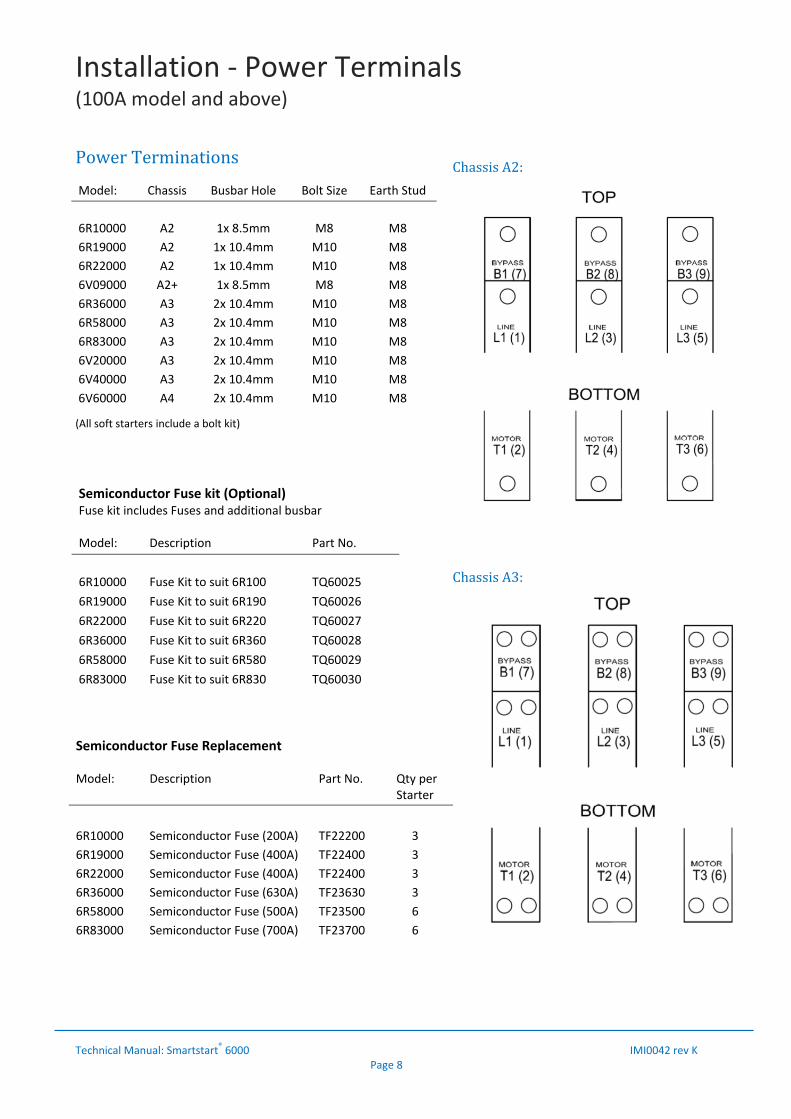
PowerTerminations (All soft starters include a bolt kit)
ChassisA2:
ChassisA3:
Semiconductor Fuse kit (Optional) Fuse kit includes Fuses and additional busbar Model: Description Part No.
6R10000 Fuse Kit to suit 6R100 TQ60025
6R19000 Fuse Kit to suit 6R190 TQ60026
6R22000 Fuse Kit to suit 6R220 TQ60027
6R36000 Fuse Kit to suit 6R360 TQ60028
6R58000 Fuse Kit to suit 6R580 TQ60029
6R83000 Fuse Kit to suit 6R830 TQ60030
Semiconductor Fuse Replacement Model: Description Part No. Qty per
Starter
6R10000 Semiconductor Fuse (200A) TF22200 3
6R19000 Semiconductor Fuse (400A) TF22400 3
6R22000 Semiconductor Fuse (400A) TF22400 3
6R36000 Semiconductor Fuse (630A) TF23630 3
6R58000 Semiconductor Fuse (500A) TF23500 6
6R83000 Semiconductor Fuse (700A) TF23700 6
Model: Chassis Busbar Hole Bolt Size Earth Stud
6R10000 A2 1x 8.5mm M8 M8
6R19000 A2 1x 10.4mm M10 M8
6R22000 A2 1x 10.4mm M10 M8
6V09000 A2+ 1x 8.5mm M8 M8
6R36000 A3 2x 10.4mm M10 M8
6R58000 A3 2x 10.4mm M10 M8
6R83000 A3 2x 10.4mm M10 M8
6V20000 A3 2x 10.4mm M10 M8
6V40000 A3 2x 10.4mm M10 M8
6V60000 A4 2x 10.4mm M10 M8

Installation ‐ Power Wiring (100A model and above)
Technical Manual: Smartstart
® 6000 IMI0042 rev K Page 9
3WireBypass
3WireContinuous(WithoutBypassContactor)NOTE: The SS6000 must have the appropriate rating to operate without a bypass contactor.
Refer to page 13 & 14 For Control Wiring
Refer to page 13 & 14 For Control Wiring
(1) Optional Fast Acting Semiconductor Fuses selected to suit the SCR devices used.
(2) Line Contactor controlled by the Soft Starter. (see Control wiring on Page 13 & 14 and application drawings on Page 46‐48)
(3) Bypass Contactor controlled by the Soft Starter. (see Control wiring on Page 13 & 14 and application drawings on Page 46‐48)
(1) Optional Fast Acting Semiconductor Fuses selected to suit the SCR devices used.
(2) Line Contactor controlled by the Soft Starter. (see Control wiring on Page 13 & 14 and application drawings on Page 46‐48)
Installation ‐ Power Wiring (100A model and above)
Technical Manual: Smartstart
® 6000 IMI0042 rev K Page 10
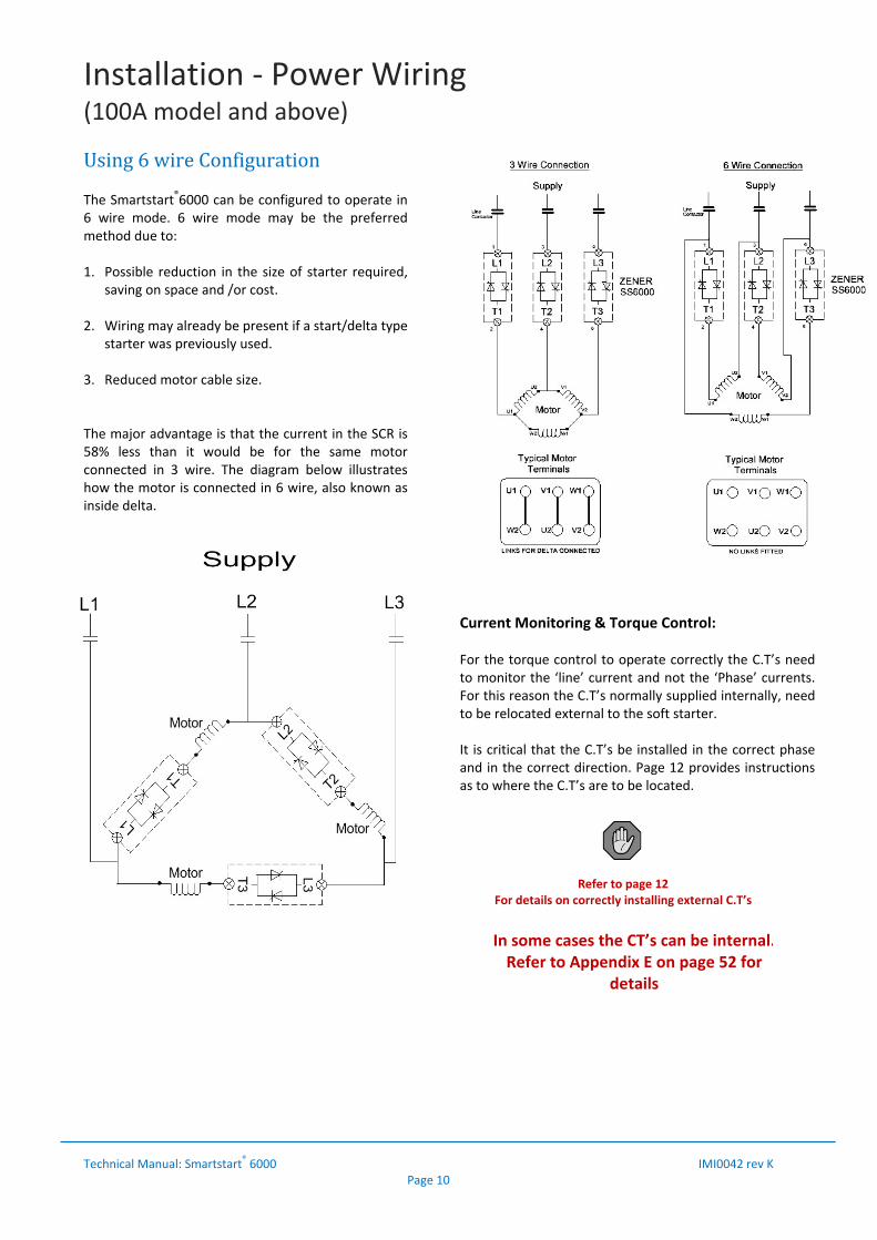
Using6wireConfigurationThe Smartstart®6000 can be configured to operate in 6 wire mode. 6 wire mode may be the preferred method due to: 1. Possible reduction in the size of starter required,
saving on space and /or cost. 2. Wiring may already be present if a start/delta type
starter was previously used. 3. Reduced motor cable size. The major advantage is that the current in the SCR is 58% less than it would be for the same motor connected in 3 wire. The diagram below illustrates how the motor is connected in 6 wire, also known as inside delta.
The following illustrates the difference between 3 wire & 6 wire connection:
Current Monitoring & Torque Control: For the torque control to operate correctly the C.T’s need to monitor the ‘line’ current and not the ‘Phase’ currents. For this reason the C.T’s normally supplied internally, need to be relocated external to the soft starter. It is critical that the C.T’s be installed in the correct phase and in the correct direction. Page 12 provides instructions as to where the C.T’s are to be located.
Refer to page 12 For details on correctly installing external C.T’s
In some cases the CT’s can be internal.Refer to Appendix E on page 52 for
details

Installation ‐ Power Wiring (100A model and above)
Technical Manual: Smartstart
® 6000 IMI0042 rev K Page 11
Standard6wireBypass
Standard6wireContinuous
Refer to page 13 & 14 For Control Wiring
Refer to page 13 & 14For Control Wiring
Refer to page 12 For details on correctly installing
external C.T’s
Refer to page 12 For details on correctly installing
external C.T’s
(1) Optional Fast Acting Semiconductor Fuses selected to suit the SCR devices used.
(2) Line Contactor controlled by the Soft Starter. (see Control wiring on Page 13 & 14 and application drawings on Page 46‐48)
(3) Bypass Contactor controlled by the Soft Starter. (see Control wiring on Page 13 & 14 and application drawings on Page 46‐48)
(1) Optional Fast Acting Semiconductor Fuses selected to suit the SCR devices used.
(2) Line Contactor controlled by the Soft Starter. (see Control wiring on Page 13 & 14 and application drawings on Page 46‐48)
Installation ‐ Power Wiring (100A model and above)
Technical Manual: Smartstart
® 6000 IMI0042 rev K Page 12
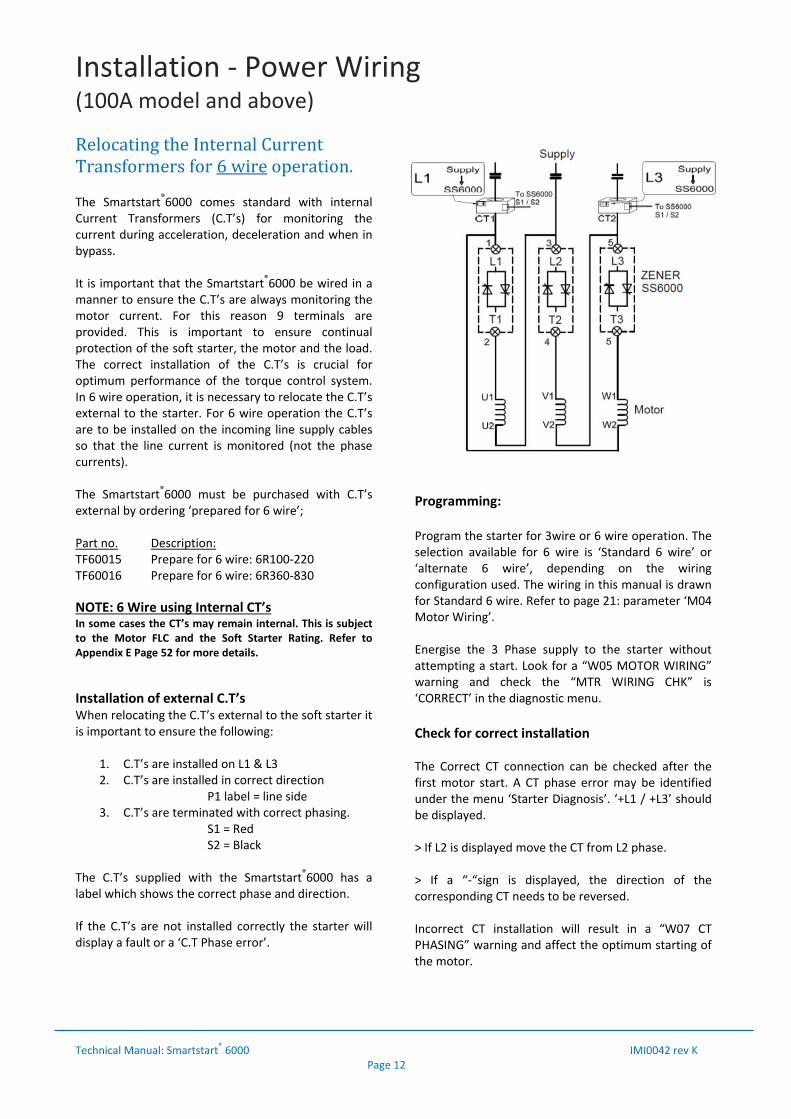
RelocatingtheInternalCurrentTransformersfor6wireoperation.The Smartstart®6000 comes standard with internal Current Transformers (C.T’s) for monitoring the current during acceleration, deceleration and when in bypass. It is important that the Smartstart®6000 be wired in a manner to ensure the C.T’s are always monitoring the motor current. For this reason 9 terminals are provided. This is important to ensure continual protection of the soft starter, the motor and the load. The correct installation of the C.T’s is crucial for optimum performance of the torque control system. In 6 wire operation, it is necessary to relocate the C.T’s external to the starter. For 6 wire operation the C.T’s are to be installed on the incoming line supply cables so that the line current is monitored (not the phase currents). The Smartstart®6000 must be purchased with C.T’s external by ordering ‘prepared for 6 wire’; Part no. Description: TF60015 Prepare for 6 wire: 6R100‐220 TF60016 Prepare for 6 wire: 6R360‐830
NOTE: 6 Wire using Internal CT’s In some cases the CT’s may remain internal. This is subject to the Motor FLC and the Soft Starter Rating. Refer to Appendix E Page 52 for more details.
Installation of external C.T’s When relocating the C.T’s external to the soft starter it is important to ensure the following:
1. C.T’s are installed on L1 & L3 2. C.T’s are installed in correct direction P1 label = line side 3. C.T’s are terminated with correct phasing.
S1 = Red S2 = Black
The C.T’s supplied with the Smartstart®6000 has a label which shows the correct phase and direction. If the C.T’s are not installed correctly the starter will display a fault or a ‘C.T Phase error’.
Programming: Program the starter for 3wire or 6 wire operation. The selection available for 6 wire is ‘Standard 6 wire’ or ‘alternate 6 wire’, depending on the wiring configuration used. The wiring in this manual is drawn for Standard 6 wire. Refer to page 21: parameter ‘M04 Motor Wiring’. Energise the 3 Phase supply to the starter without attempting a start. Look for a “W05 MOTOR WIRING” warning and check the “MTR WIRING CHK” is ‘CORRECT’ in the diagnostic menu. Check for correct installation The Correct CT connection can be checked after the first motor start. A CT phase error may be identified under the menu ‘Starter Diagnosis’. ‘+L1 / +L3’ should be displayed. > If L2 is displayed move the CT from L2 phase. > If a “‐“sign is displayed, the direction of the corresponding CT needs to be reversed. Incorrect CT installation will result in a “W07 CT PHASING” warning and affect the optimum starting of the motor.
Control Wiring
Technical Manual: Smartstart
® 6000 IMI0042 rev K Page 13
+
-
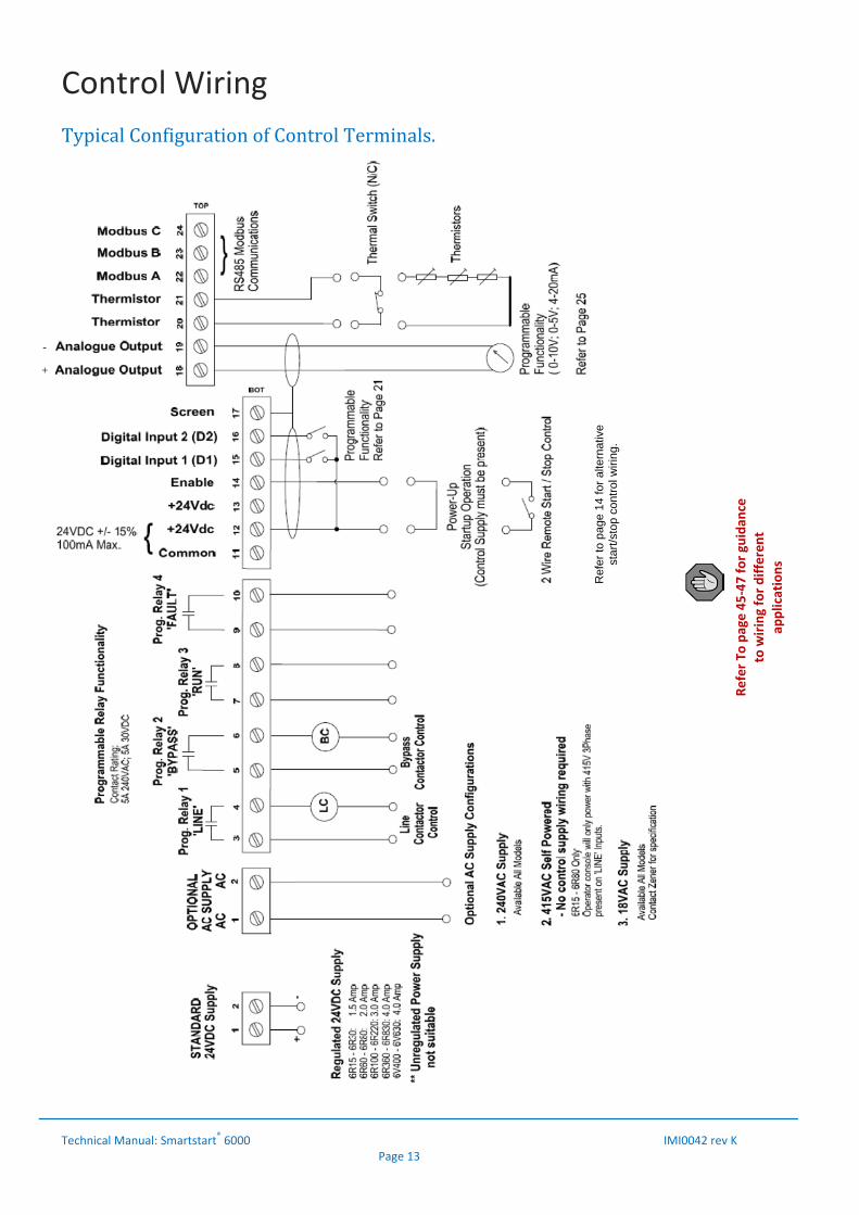
TypicalConfigurationofControlTerminals.
Refer To
page 45‐47 for guidan
ce
to wiring for different
applications
Ref
er to
pag
e 14
for
alte
rnat
ive
star
t/sto
p co
ntro
l wiri
ng.

Control Wiring
Technical Manual: Smartstart
® 6000 IMI0042 rev K Page 14
Default/StandardControl: 1. Standard Power‐up Start (no Soft Stop)
2. Standard Run/Stop using enable input (Soft Start/Soft Stop or Coast) C20 Decel Ramp : 0.0 for coast : Adjust for soft stop (>0) If enable is left on, power‐up start will be supported
3. Standard Run/stop using built‐in 24hour cycle timer Start/stop by internal timer. See page 28 for details
Alternativeconfigurationavailable: 1. 3 wire Start/Stop A53 Start Logic : ‘edge sensed’ X10 Dig In 1 : Enabled X11 Dig In 1 Variable : Start (latching) X11 Dig In 1 Delay : 0.0sec Use enable or DIG in2 for stop: X20 Dig In 2 : Invert X21 Dig In 2 Variable : Stop X22 Dig In 2 Delay : 0.0sec C20 Decel Ramp : 0.0 for coast : Adjust for soft stop (>0)
2. Delayed Soft Start and/or Soft Stop Multiple pump control systems or prestart warning A X10 Dig In 1 : Enabled X11 Dig In 1 Variable : Start (latching) X11 Dig In 1 Delay : Adjust to suit (0‐300seconds) X20 Dig In 2 : Invert X21 Dig In 2 Variable : Stop X22 Dig In 2 Delay : Adjust to suit (0‐300seconds) (Adjust Accel and Decel to suit application)
Control Supply
24VDC 12/13
ENABLE 14
DIGIn 1 15
DIGIn 2 16
RUN / STOP
Control Supply
24VDC 12/13
ENABLE 14
DIGIn 1 15
DIGIn 2 16 Control Supply
24VDC 12/13
ENABLE 14
DIG In 1 15
DIG In 2 16 START
STOP
Control Supply
24VDC 12/13
ENABLE 14
DIG In 1 15
DIG In 2 16
START
STOP
Control Supply
24VDC 12/13
ENABLE 14
Relay 3 or 4 ‘TIMER RELAY’
Network Connections
Technical Manual: Smartstart
® 6000 IMI0042 rev K Page 15
ModbusRS485
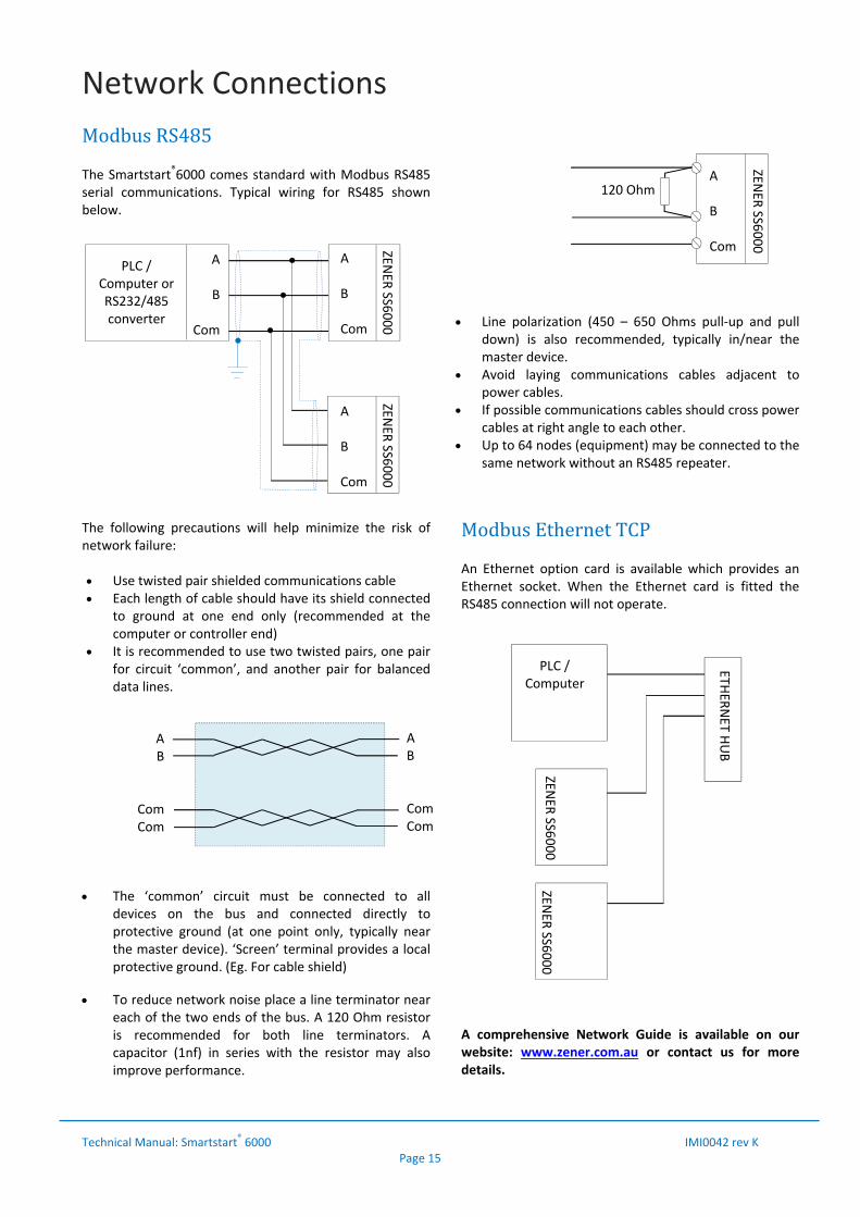
The Smartstart®6000 comes standard with Modbus RS485 serial communications. Typical wiring for RS485 shown below. The following precautions will help minimize the risk of network failure: Use twisted pair shielded communications cable Each length of cable should have its shield connected
to ground at one end only (recommended at the computer or controller end)
It is recommended to use two twisted pairs, one pair for circuit ‘common’, and another pair for balanced data lines.
The ‘common’ circuit must be connected to all
devices on the bus and connected directly to protective ground (at one point only, typically near the master device). ‘Screen’ terminal provides a local protective ground. (Eg. For cable shield)
To reduce network noise place a line terminator near
each of the two ends of the bus. A 120 Ohm resistor is recommended for both line terminators. A capacitor (1nf) in series with the resistor may also improve performance.
Line polarization (450 – 650 Ohms pull‐up and pull
down) is also recommended, typically in/near the master device.
Avoid laying communications cables adjacent to power cables.
If possible communications cables should cross power cables at right angle to each other.
Up to 64 nodes (equipment) may be connected to the same network without an RS485 repeater.
ModbusEthernetTCPAn Ethernet option card is available which provides an Ethernet socket. When the Ethernet card is fitted the RS485 connection will not operate. A comprehensive Network Guide is available on our website: www.zener.com.au or contact us for more details.
PLC / Computer or RS232/485 converter
A B Com
A
B
Com
A B Com
A B Com
ZENER
SS6000
ZENER
SS6000
ZENER
SS6000
120 Ohm
A B
Com Com
AB Com Com
PLC / Computer
ZENER
SS6000
ZENER
SS6000
ETHER
NET H
UB
Programming
Technical Manual: Smartstart® 6000 IMI0042 rev K Page 16
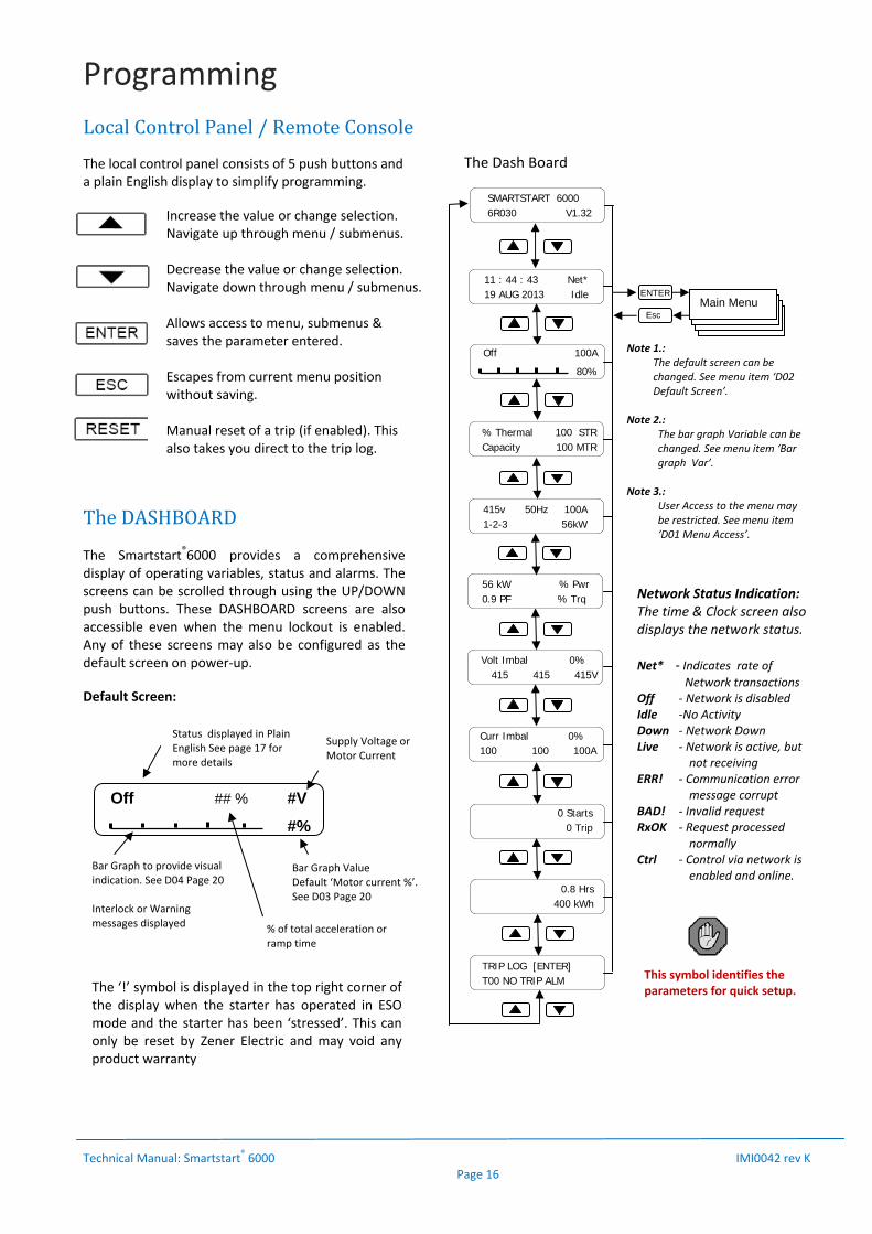
LocalControlPanel/RemoteConsole The local control panel consists of 5 push buttons and a plain English display to simplify programming.
Increase the value or change selection. Navigate up through menu / submenus. Decrease the value or change selection. Navigate down through menu / submenus. Allows access to menu, submenus & saves the parameter entered. Escapes from current menu position without saving. Manual reset of a trip (if enabled). This also takes you direct to the trip log.
TheDASHBOARDThe Smartstart®6000 provides a comprehensive display of operating variables, status and alarms. The screens can be scrolled through using the UP/DOWN push buttons. These DASHBOARD screens are also accessible even when the menu lockout is enabled. Any of these screens may also be configured as the default screen on power‐up. Default Screen:
The Dash Board
Off ## % #V
#%
Status displayed in Plain English See page 17 for more details
Supply Voltage orMotor Current
Bar Graph ValueDefault ‘Motor current %’. See D03 Page 20
Bar Graph to provide visual indication. See D04 Page 20 Interlock or Warning messages displayed
ENTER
11 : 44 : 43 Net* 19 AUG 2013 Idle
% Thermal 100 STR Capacity 100 MTR
415v 50Hz 100A 1-2-3 56kW
56 kW % Pwr 0.9 PF % Trq
Volt Imbal 0% 415 415 415V
Curr Imbal 0% 100 100 100A
0 Starts 0 Trip
0.8 Hrs 400 kWh
TRIP LOG [ENTER] T00 NO TRIP ALM
Esc Main Menu
Off 100A
80%
Note 1.: The default screen can be
changed. See menu item ‘D02 Default Screen’.
Note 2.: The bar graph Variable can be
changed. See menu item ‘Bar graph Var’.
Note 3.:
User Access to the menu may be restricted. See menu item ‘D01 Menu Access’.
Network Status Indication: The time & Clock screen also displays the network status. Net* ‐ Indicates rate of Network transactions Off ‐ Network is disabled Idle ‐No Activity Down ‐ Network Down Live ‐ Network is active, but
not receiving ERR! ‐ Communication error
message corrupt BAD! ‐ Invalid request RxOK ‐ Request processed
normally Ctrl ‐ Control via network is
enabled and online.
SMARTSTART 6000 6R030 V1.32
This symbol identifies the parameters for quick setup. The ‘!’ symbol is displayed in the top right corner of
the display when the starter has operated in ESO mode and the starter has been ‘stressed’. This can only be reset by Zener Electric and may void any product warranty
% of total acceleration or ramp time

Programming
Technical Manual: Smartstart® 6000 IMI0042 rev K Page 17
OperatingStatusIndication
‘Off’ : The Smartstart®6000 has control power applied but not enabled and no line supply.
‘Standby’ : The Smartstart®6000 has been enabled to start and the run relay energized to bring in the line contactor (if installed). The Smartstart®6000 will initiate a start immediately 3 phase supply is applied.
‘Ready’ : Line supply on but nor enabled.
‘ACCEL ##%’ : The Smartstart®6000 is accelerating the motor. Ramp time completed (%) & Motor Current (A) displayed.
‘At Speed ##%’ : The motor is at full speed, the accel time period may not be complete. Ramp time completed (%) & Motor Current (A) is displayed.
‘Run Bypass or Run Cont.’ : The ramp time is complete and the bypass contactor operated or SCR’s are in full conduction. Motor Current (A) is displayed.
‘DECEL ##%’ : The Smartstart®6000 is decelerating the motor. Ramp time completed (%) & Motor Current (A) displayed
‘Start Req’ : Enabled, but start delayed/postponed due to cooling or start timer delay.
‘Kick Start’: Kick start is active.
‘Motor Off’: Brief message as motor defluxes or Pending motor loss trip.
‘Tripped’: System has tripped. (Not seen in Auto retart)
‘Cooling’: Starter too hot to start or during “Minimum off time”.
‘Shut down’: PSU under voltage detected (SMARTSTART shutting down).
‘Brownout’: Sustained PSU under voltage condition (supply problem/fault).
‘AR Pending’: System tripped but waiting for auto restart.
‘AR Lockout’: Final trip after all AR attempts exhausted.
Warnings,AlarmsandMessages:The Smartstart®6000 has been designed to provide the user with a comprehensive display of its operating status. Messages in plain English are flashed across the screen (if enabled) to alert the user of its current status, any warnings, trips or pending actions. The code will have a prefix of T (trip), W (Warning) or I (Interlock). Example 1: If auto restart is selected it will flash: ‘AR PENDING’, the number of restarts and time before a restart. Example 2: If the motor or starter has reached a thermal state where cannot restart it will flash: ‘PENDING, I30 MTR OVERLOAD’ ‘FLASH ALERTS’ (Top Line of Display) The Smartstart®6000 can be configured to Flash Warning & Alarm messages irrespective of the DASHBOARD screen currently active. See ‘D05 Warning alarms’ on page 21. These alerts include:
PENDING WARNING TRIPPED OVERRIDE AR #12 in 1234s AR#12 Anytime LOCKOUT
Refer to table 4 on page 34 for explanation of each. ‘ALARMS and interlock Messages The Smartstart®6000 can be configured to Display the Trip code and Description over the bar graph on the default screen. Interlock messages can also be displayed. See ‘D06 Alm over bar’ on page 21.
Interlock Messages When this feature is enabled (ie. D06 ‐ ‘All Alarms’) interlock messages are displayed on the 2nd line. Refer to ‘D06 Warning Alarms’ for more information). Interlock messages have an ‘I’ prefix. Eg. ‘I70EnableOFF’ . These messages provide more information about the current status of the starter and provide diagnostics to why the motor may not be operating. Refer to page 35 & 36 for explanation of these messages.
ACCEL 50 % 250A
300%
Current status % of Accel or Decel time
Actual Current
Current as % of motor FLC. (Programmable)
Bar Graph displaying current%

Programming
Technical Manual: Smartstart® 6000 IMI0042 rev K Page 18
ESC
ENTER
ENTER Op Code
% of ramp time
Log Number
TRIP Code
Operating state at time
ESC
TripLog: The trip log is accessed from the ‘Trip status’ screen. The ‘Trip status’ screen is the last DASHBOARD screen (or press the reset button). The “Trip status’ screen displays the last trip. To access the trip log press [ENTER]
[Trip status screen] ENTER
[Trip Log #1 screen]
Ifnotripshaveoccurred:
For all trip codes and descriptions refer to page 36.
TheTripLogMessage:
Each trip log shows: 1. Log Number: L01 (most recent) to L10 (Oldest). 2. Date & Time of trip. 3. The Trip code and description. See trip codes. 4. ‘Op Code’ = Indicates the operating state when
the trip occurred.
A = Accel ##% Accel Ramp up (with ramp timer progress) B = Run Bypass; Bypass contactor closed C = Run Continuous D = Decel ##% (with ramp timer progress) K = Kick Start U = Atspd #% Motor up to speed (with ramp timer progress)
HowtoResetafteratrip.To reset the starter press the reset button for 3 seconds. The display will countdown ‘3…2…1…Resetting fault’. The trip will be logged into the fault log. The reset function can be configured multiple ways. Refer to ‘5 Reset/Restart’ Menu and page 26 for more information.
Trip Log [ENTER]
T60 MOTOR FAULT
L01 04 Jan 2014
00:12:17 A->T60
L01 Accel 1% ->
T60 MOTOR FAULT
L10 01 Jan 2014
00:08:17 A->T60
L01 04 Jan 2014
00:12:17 A->T60
L01 Accel 1% ->
T60 MOTOR FAULT
Trip Log [ENTER]
No Alarms
[Alternate Trip Log screen]
Programming
Technical Manual: Smartstart® 6000 IMI0042 rev K Page 19
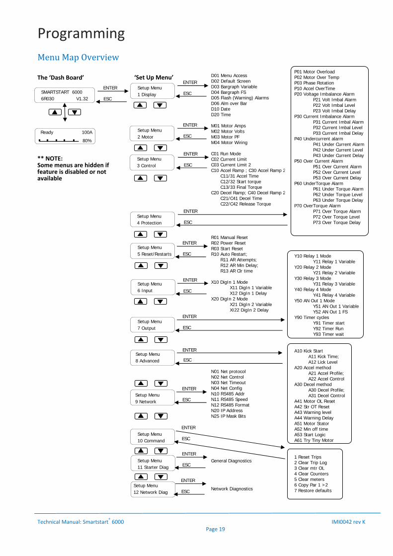
MenuMapOverview
D01 Menu AccessD02 Default Screen D03 Bargraph Variable D04 Bargraph FS D05 Flash (Warning) Alarms D06 Alm over Bar D10 Date D20 Time M01 Motor Amps M02 Motor Volts M03 Motor PF M04 Motor Wiring C01 Run Mode C02 Current Limit C03 Current Limit 2 C10 Accel Ramp ; C30 Accel Ramp 2 C11/31 Accel Time C12/32 Start torque C13/33 Final Torque C20 Decel Ramp; C40 Decel Ramp 2 C21/C41 Decel Time C22/C42 Release Torque R01 Manual Reset R02 Power Reset R03 Start Reset R10 Auto Restart; R11 AR Attempts; R12 AR Min Delay; R13 AR Clr time X10 DigIn 1 Mode X11 DigIn 1 Variable X12 DigIn 1 Delay X20 DigIn 2 Mode X21 DigIn 2 Variable XI22 DigIn 2 Delay N01 Net protocol N02 Net Control N03 Net Timeout N04 Net Config N10 RS485 Addr N11 RS485 Speed N12 RS485 Format N20 IP Address N25 IP Mask Bits General Diagnostics Network Diagnostics
The ‘Dash Board’ ‘Set Up Menu’
SMARTSTART 6000 6R030 V1.32
Ready 100A
80%
Setup Menu 1 Display
Setup Menu 2 Motor
Setup Menu 3 Control
Setup Menu 4 Protection
Setup Menu 6 Input
Setup Menu 7 Output
Setup Menu 5 Reset/Restarts
Setup Menu 8 Advanced
Setup Menu 10 Command
Setup Menu 11 Starter Diag
ENTER
ESC
P01 Motor OverloadP02 Motor Over Temp P03 Phase Rotation P10 Accel OverTime P20 Voltage Imbalance Alarm P21 Volt Imbal Alarm P22 Volt Imbal Level P23 Volt Imbal Delay P30 Current Imbalance Alarm P31 Current Imbal Alarm P32 Current Imbal Level P33 Current Imbal Delay P40 Undercurrent alarm P41 Under Current Alarm P42 Under Current Level P43 Under Current Delay P50 Over Current Alarm P51 Over Current Alarm P52 Over Current Level P53 Over Current Delay P60 UnderTorque Alarm P61 Under Torque Alarm P62 Under Torque Level P63 Under Torque Delay P70 OverTorque Alarm P71 Over Torque Alarm P72 Over Torque Level P73 Over Torque Delay Y10 Relay 1 Mode Y11 Relay 1 Variable Y20 Relay 2 Mode Y21 Relay 2 Variable Y30 Relay 3 Mode Y31 Relay 3 Variable Y40 Relay 4 Mode Y41 Relay 4 Variable Y50 AN Out 1 Mode Y51 AN Out 1 Variable Y52 AN Out 1 FS Y90 Timer cycles Y91 Timer start Y92 Timer Run Y93 Timer wait A10 Kick Start A11 Kick Time; A12 Lick Level A20 Accel method A21 Accel Profile; A22 Accel Control A30 Decel method A30 Decel Profile; A31 Decel Control A41 Motor OL Reset A42 Str OT Reset A43 Warning level A44 Warning Delay A51 Motor Stator A52 Min off time A53 Start Logic A61 Try Tiny Motor 1 Reset Trips 2 Clear Trip Log 3 Clear mtr OL 4 Clear Counters 5 Clear meters 6 Copy Par 1 >2 7 Restore defaults
ENTER
ESC
ENTER
ESC
ENTER
ESC
ENTER
ESC
ENTER
ESC
ENTER
ESC
ENTER
ESC
Setup Menu 9 Network
ENTER
ESC
ENTER
ESC
ENTER
ESC Setup Menu 12 Network Diag
ENTER
ESC
ENTER
ESC
** NOTE: Some menus are hidden if feature is disabled or not available

Programming
Technical Manual: Smartstart® 6000 IMI0042 rev K Page 20
MenuNavigation
D01 Menu Access: Sets the desired user access to menu.
Selection: Disabled; Setup; Read only Default: Setup To save changes To exit without saving
If the menu access is disabled a user access code is required to access the menu. The access code is 1470.
D02 Default Screen: The default screen is the dashboard screen that the Soft Starter will return to ‐ on power up, exit or time‐out from the menu.
Selection: Overview; Thermal; Electrical; Power; Volt imbal; Curr imbal; Counters; meters; clock/net
Default: Overview To save changes To exit without saving
D03 Bargraph Var.:
Sets the bargraph variable to monitor & Display.
Selection: Mtr current; Mtr Torque; Mtr Thermal; SCR Thermal; Active
Power; Power Factor Default: Mtr Current To save changes To exit without saving
D04 Bargraph FS.: Adjust the full scale of the bar graph meter as a percentage.
Selection: 100;120;150;200;300;400;600 Default: 300% To save changes To exit without saving
Setup Menu
1 Display
MENU ACCESS
Read Only
LOGIN CODE
> 1470
3 sec * Press <Enter> for 3 seconds.
Setup Menu 1 Display
Esc
Setup Menu 2 Motor
Setup Menu 3 Control
Off 0V
0%
Setup Menu 4 Protection
Setup Menu 5 Reset /Restarts
Setup Menu 6 Input
Setup Menu 7 Output
Setup Menu 8 Advanced
Setup Menu 10 Command
Dashboard screen (1 of 11)
Enter
Refer to Page 20
Refer to Page 21
Refer to Page 21
Refer to Page 23
Refer to Page 27
Refer to Page 26
Refer to Page 27
Refer to Page 29
Refer to Page 32
Setup Menu 11 Starter Diag
Refer to Page 32
Setup Menu 9 Network
Refer to Page 31 & the ‘SS6000 Network Guide’
Setup Menu 12 Network Diag
Refer to Page 33
Programming
Technical Manual: Smartstart® 6000 IMI0042 rev K Page 21
D05 (Flash) Warnings/Alarms: General inclusion of warning alarms to be ‘flashed over’ the current dashboard screen. Refer to table 4 (p35 & 36) for alarm message explanation.
Selection: All Alarms; Disabled; Trips only; Flt Warnings; Major Warnings
Default: All Alarms To save changes To exit without saving
D06 Alm over Bar: The default screen will display when a trip has occurred, with details of the type of trip in the trip log. The Smartstart®6000 may be configured to display the trip or alarm warning on the default screen (over the bar graph). The highest priority active alarm is displayed in place of the bar graph (only when the motor is off). Refer to table 5 (p35 & 36) for alarm message explanation.
Selection: All Alarms; Disabled; Trips only; Flt Warnings; Major Warnings
Default: All Alarms To save changes To exit without saving
Level/Option: Description:
1/Trips Only Only displays ‘trip’ Alarms (T##). Incl. Tripped, AR & Lockout alerts.
2/Flt Warnings: Include fault warning alarms: (W02,22,15,14,11,05,07,32,08,06)
3/Major Warnings: Include major warning alarms: (W02,04,13,23,21,20,31,30,24,25,26)
4/All Warnings: Include remaining (minor) alarms (W37,38,41,33,35,34,36)
5/All Alarms: Include interlock warning alarms (see ‘I’ message/alarms on page 36)
D10 Date: Set the date of real time clock
Adjust the value of time To save changes To exit without saving
D20 Time:
Set the time of real time clock
Adjust the value of time To save changes To exit without saving
M01 Motor Amps:
Adjust to the value of motor full load current (FLC) indicated on the motor rating plate, even if connected in 6 wire (inside delta).
Range: 40% of Nom. unit rating to max. rating Default: Nom. rating of unit To save changes To exit without saving [‘Nom. unit rating’ = 3wire, bypass, light duty]
M02 Motor Volts: Adjust the value to the motor nameplate voltage.
Range: 199 – 481V [480 ‐1160V] Default: 415V [1000V] To save changes To exit without saving
M03 Motor PF: Adjust to the value to the motor Power Factor as indicated on the motor rating plate.
Range: 0.60 – 0.98 Default: 0.90 To save changes To exit without saving
M04 Motor Wiring: (excl. 6R15‐6R80) Select the wiring configuration of the soft starter.
Range: 3 Wire; Std 6 Wire; Alt 6 Wire Default: 3 Wire To save changes To exit without saving
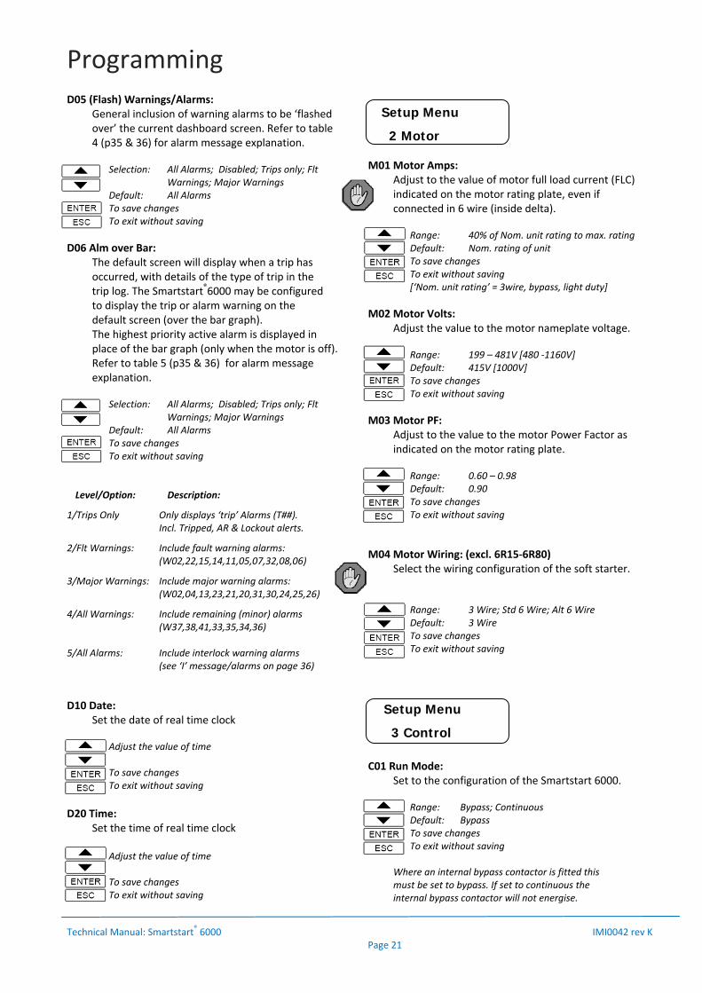
C01 Run Mode: Set to the configuration of the Smartstart 6000.
Range: Bypass; Continuous Default: Bypass To save changes To exit without saving
Where an internal bypass contactor is fitted this must be set to bypass. If set to continuous the internal bypass contactor will not energise.
Setup Menu
2 Motor
Setup Menu
3 Control
Programming
Technical Manual: Smartstart® 6000 IMI0042 rev K Page 22
C02 Current Limit: The current limit is expressed as a percentage of the entered motor Amps (FLC). This current limit setting operates during the ramp time only and will over‐ride the torque settings. Reducing the current limit will limit the torque available to the motor and load. If set too low it may prevent the motor from accelerating or reaching full speed.
Range: 100 to 450% FLC Default: 450% To save changes To exit without saving
Appendix A – Page 44 provides a guide to starting parameters for various load types.
C03 Current Limit 2: (2nd Parameter Enabled)
Current limit setting for 2nd parameters when enabled and activated used digital input 1 or 2.
Range: 100 to 450% FLC Default: 450% To save changes To exit without saving
C10 Accel Ramp:
To enter submenu to modify To exit sub menu
C11 Accel Time: Adjust this to vary the time taken to ramp the voltage to full supply voltage or the torque to reach the ‘finish torque’. The accel time will affect the actual current during starting – the faster the rate of acceleration the higher the start current.
Range: 1 to 60 seconds Default: 10 s To save changes To exit without saving
C12 Start Torque: The initial torque provided when a start is initiated. Adjust to the lowest setting which allows the motor to turn on a start command. This is entered as a percentage of nominal Torque (FLT). This setting will be dependent on the torque required by the load.
Range: 0% to 200% Default: 30% To save changes To exit without saving
C13 Final Torque: (torque control only) This sets the torque provided at the end of the acceleration period. This is entered as a percentage of nominal Torque (FLT).
Range: 15 to 200% Default: 100% To save changes To exit without saving
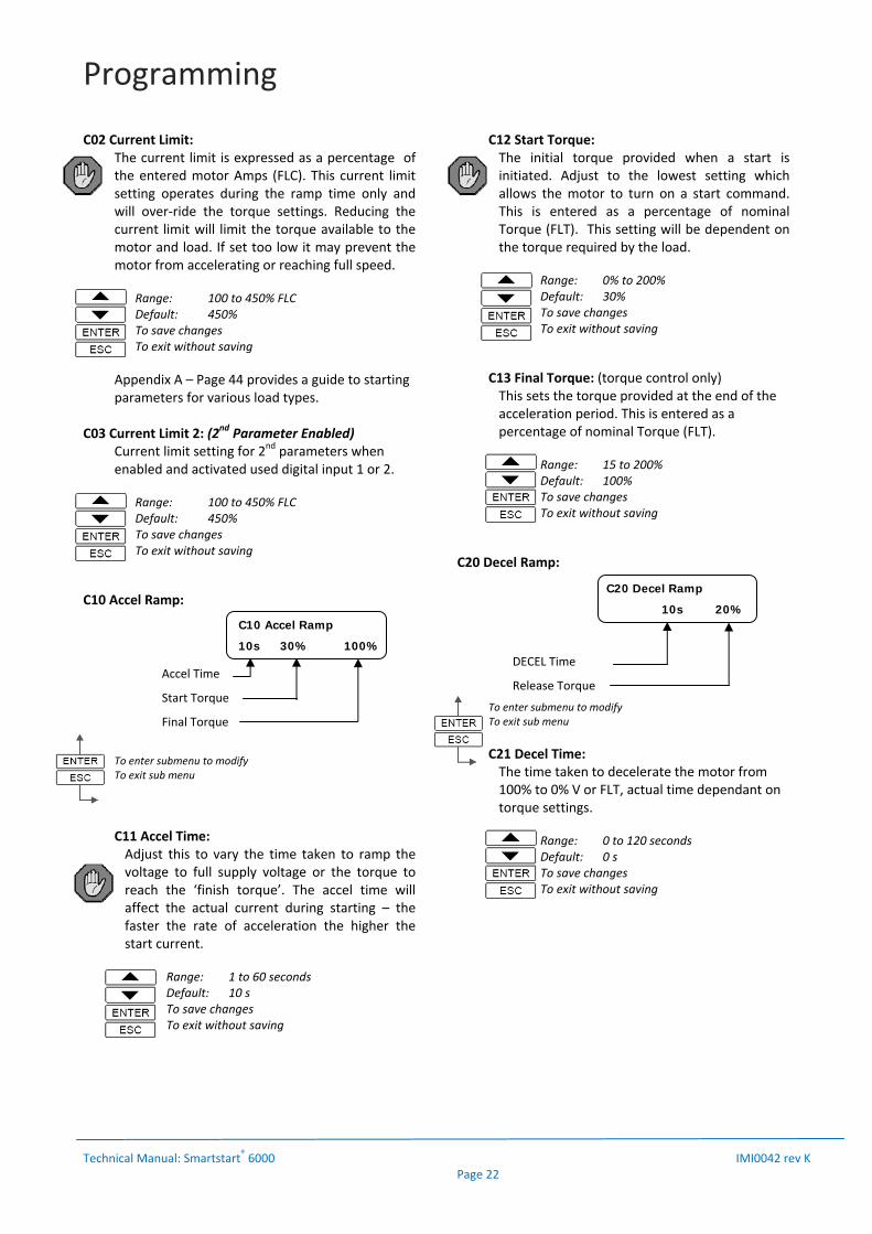
C20 Decel Ramp:
To enter submenu to modify To exit sub menu
C21 Decel Time: The time taken to decelerate the motor from 100% to 0% V or FLT, actual time dependant on torque settings.
Range: 0 to 120 seconds Default: 0 s To save changes To exit without saving
C10 Accel Ramp
10s 30% 100%
Accel Time
Start Torque
Final Torque
DECEL Time
Release Torque
C20 Decel Ramp
10s 20%
Programming
Technical Manual: Smartstart® 6000 IMI0042 rev K Page 23
C22 Release Torq: The Smartstart®6000 will decelerate the motor at the ‘decel time’ rate until the torque reaches the release torque value entered. This is entered as a percentage of nominal Torque (FLT).
Range: 0 to 100% Default: 20% To save changes To exit without saving
In pump applications the deceleration provided by the Smartstart®6000 will reduce problems with water hammer with greater control of the motor torque & speed. The Smartstart®6000 has advanced settings to customise the control of the motor during acceleration and deceleration. Refer to Menu ‘Advanced Controls’ on page 29 for more details. C30 Accel Ramp 2: (2nd Parameter Enabled)
C31 Accel Time 2: Accel Ramp for 2nd parameter operation when enabled and activated used digital input 1 or 2.
Range: 1 to 60 seconds Default: 10 s To save changes To exit without saving
C32 Start Torque 2: The initial torque for 2nd parameter operation.
Range: 0% to 200% Default: 30% To save changes To exit without saving
C33 Final Torque 2: (torque control only) This sets the torque provided at the end of the acceleration period.
Range: 15 to 200% Default: 100% To save changes To exit without saving
C40 Decel Ramp: (2nd Parameter Enabled)
C21 Decel Time: The time taken to decelerate the motor from 100% to 0% V or FLT for 2nd parameter operation
Range: 0 to 120 seconds Default: 0 s To save changes To exit without saving
C42 Release Torq: Release Torque for 2nd parameter operation
. Range: 0 to 100% Default: 20% To save changes To exit without saving
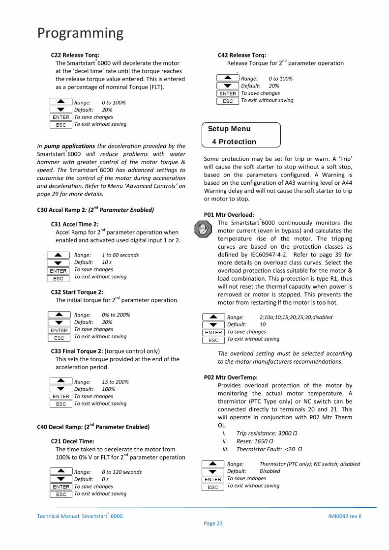
Some protection may be set for trip or warn. A ‘Trip’ will cause the soft starter to stop without a soft stop, based on the parameters configured. A Warning is based on the configuration of A43 warning level or A44 Warning delay and will not cause the soft starter to trip or motor to stop. P01 Mtr Overload:
The Smartstart®6000 continuously monitors the motor current (even in bypass) and calculates the temperature rise of the motor. The tripping curves are based on the protection classes as defined by IEC60947‐4‐2. Refer to page 39 for more details on overload class curves. Select the overload protection class suitable for the motor & load combination. This protection is type R1, thus will not reset the thermal capacity when power is removed or motor is stopped. This prevents the motor from restarting if the motor is too hot.
Range: 2;10a;10;15;20;25;30;disabled Default: 10 To save changes To exit without saving
The overload setting must be selected according to the motor manufacturers recommendations.
P02 Mtr OverTemp:
Provides overload protection of the motor by monitoring the actual motor temperature. A thermistor (PTC Type only) or NC switch can be connected directly to terminals 20 and 21. This will operate in conjunction with P02 Mtr Therm OL. i. Trip resistance: 3000 Ω ii. Reset: 1650 Ω iii. Thermistor Fault: <20 Ω
Range: Thermistor (PTC only); NC switch; disabled Default: Disabled To save changes To exit without saving
Setup Menu
4 Protection
Programming
Technical Manual: Smartstart® 6000 IMI0042 rev K Page 24
P03 Ph Rotation: Selectable phase sequence protection to inhibit motor operation if a prohibited phase sequence is detected (ie. reverse operation). Ideal for pumping applications.
Range: Ignore; 1‐2‐3; 3‐2‐1; Default: Ignore To save changes To exit without saving
P10 Acc Overtime :
To enter submenu to modify To exit sub menu
P11 Overtime Alarm: Protection against the start time exceeding the preset acceleration or ramp time.
Range: off; trip; warn Default: off To save changes To exit without saving
P12 Overtime Del: The time exceeding the set ramp time before a trip on Accel overtime occurs.
Range: 5 – 300 secs Default: 120s To save changes To exit without saving
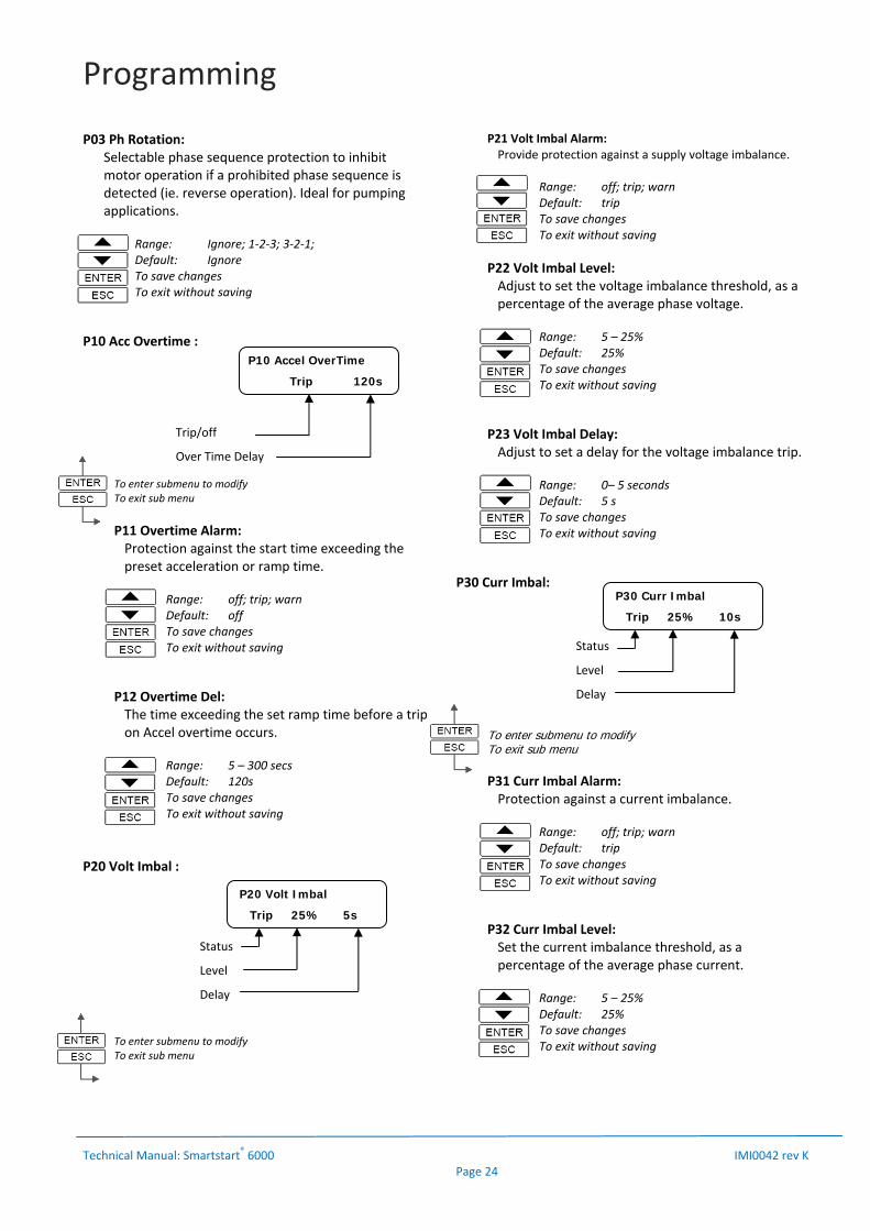
P20 Volt Imbal :
To enter submenu to modify To exit sub menu
P21 Volt Imbal Alarm: Provide protection against a supply voltage imbalance.
Range: off; trip; warn Default: trip To save changes To exit without saving
P22 Volt Imbal Level: Adjust to set the voltage imbalance threshold, as a percentage of the average phase voltage.
Range: 5 – 25% Default: 25% To save changes To exit without saving
P23 Volt Imbal Delay: Adjust to set a delay for the voltage imbalance trip.
Range: 0– 5 seconds Default: 5 s To save changes To exit without saving
P30 Curr Imbal:
To enter submenu to modify To exit sub menu
P31 Curr Imbal Alarm: Protection against a current imbalance.
Range: off; trip; warn Default: trip To save changes To exit without saving
P32 Curr Imbal Level: Set the current imbalance threshold, as a percentage of the average phase current.
Range: 5 – 25% Default: 25% To save changes To exit without saving
Status
Level
Delay
P20 Volt Imbal
Trip 25% 5s
Status
Level
Delay
P30 Curr Imbal
Trip 25% 10s
Trip/off
Over Time Delay
P10 Accel OverTime
Trip 120s

Programming
Technical Manual: Smartstart® 6000 IMI0042 rev K Page 25
P33 Curr Imbal Delay: Set a delay for the current imbalance trip.
Range: 0 – 10 seconds Default: 10s To save changes To exit without saving
P40 Undercurrent:
To enter submenu to modify To exit sub menu
P41 Undercurrent Alarm: Protection against under current. This protection is not active during accel & decel period. Active when motor is up to speed.
Range: off; trip; warn Default: off To save changes To exit without saving
Ideal for detecting loss of load or low load conditions such as belt breakages or blocked water pipes. ‘Trip’: The soft starter trips , stops the motor and indicates an ‘undercurrent trip’. The Trip relay will change state if selected. ‘Warn’: The soft starter does not trip or stop the motor. See D05 & D06 for more information regarding warning alarms.
P42 Undercurrent Level: Adjust to the desired trip threshold, as a percentage (%) of the Motor Amps.
Range: 10 – 100% Default: 10% To save changes To exit without saving
P43 Undercurrent Delay: Adjust to set the time period that the current must fall below the threshold before a trip occurs.
Range: 1‐90 seconds Default: 10 s To save changes To exit without saving
P50 Overcurrent:
To enter submenu to modify To exit sub menu
P51 Overcurrent Alarm: Provide protection against over current. This protection is not active during the accel & decel period.
Range: off; trip; warn Default: off To save changes To exit without saving
‘Trip’: The soft starter trips, stops the motor and indicates an ‘over current trip’. The Trip relay will change state if selected. ‘Warn’: The soft starter does not trip or stop the motor. See D05 & D06 for more information regarding warning alarms.
P52 Overcurrent Level: Adjust to the desired trip threshold, as a percentage (%) of the Motor Amps.
Range: 80 – 250% Default: 100% To save changes To exit without saving
P53 Overcurrent Delay: Adjust to set the time period that the current must exceed the threshold before a trip occurs.
Range: 0 ‐ 30 seconds Default: 10 s To save changes To exit without saving
P60 Under Torque:
To enter submenu to modify To exit sub menu
Status
Level
Delay
P40 Undercurrent
Trip 5% 5s
Status
Level
Delay
P50 Overcurrent
Trip 110% 2s
Status
Level
Delay
P60 Under Torque
Trip 10% 10s

Programming
Technical Manual: Smartstart® 6000 IMI0042 rev K Page 26
P61 Under torque Alarm: Provide protection against under‐torque. This protection is not active during the accel & decel period.
Range: off; trip; warn Default: off To save changes To exit without saving
‘Trip’: The soft starter trips, stops the motor and indicates an ‘Under Torque trip’. The Trip relay will change state if selected. ‘Warn’: The soft starter does not trip or stop the motor. See D05 & D06 for more information regarding warning alarms.
P62 Under Torque Level: Adjust to the desired trip threshold, as a percentage of nominal torque.
Range: 10 – 100% Default: 10% To save changes To exit without saving
P63 Under Torque Delay: Adjust to set the time period that the torque must fall below the threshold before a trip occurs.
Range: 1 ‐ 90 seconds Default: 10 s To save changes To exit without saving
P70 Over Torque (Electronic Shear Pin):
Electronic Shear Pin or protection against over torque. This protection is not active during the accel & decel period.
To enter submenu to modify To exit sub menu
P71 Over Torque Alarm: Provide protection against excess torque. This protection is not active during the accel & decel period.
Range: off; trip; warn Default: off To save changes To exit without saving
‘Trip’: The soft starter trips, stops the motor and indicates an ‘Over Torque trip’. The Trip relay will change state if selected. ‘Warn’: The soft starter does not trip or stop the motor. See D05 & D06 for more information regarding warning alarms.
P72 Over Torque Level: Adjust to the desired trip threshold, as a percentage of nominal torque.
Range: 80 – 250% Default: 100% To save changes To exit without saving
P73 Over Torque Delay:
Adjust to set the time period that the torque must exceed the threshold before a trip occurs.
Range: 0 ‐ 30 seconds Default: 10 s To save changes To exit without saving
R01 Manual Reset Activate or de‐activate the manual reset ie. The reset on the local console.
Range: Enable; Disable Default: Enable To save changes To exit without saving
R02 Power Reset Activate or de‐activate reset on removal of control supply.
Range: Enable; Disable Default: Enable To save changes To exit without saving
Status
Level
Delay
P70 Over Torque
Trip 100% 5s
Setup Menu
5 Reset / Restarts

Programming
Technical Manual: Smartstart® 6000 IMI0042 rev K Page 27
R03 Start Reset Activate or de‐activate reset on a start command.
Range: Enable; Disable Default: Disabled To save changes To exit without saving
R10 Auto Restart
R11 AR Attempts Enter number of restart attempts.
Range: 0 ‐ 15 Default: 0 = Disabled To save changes To exit without saving
R12 AR Min Delay Enter Minimum delay before restart attempt.
Range: 5 – 3600 seconds Default: 10 seconds To save changes To exit without saving
R13 AR Clear Time Enter time period the soft starter must run for to reset the ‘R11 AR attempt log’ to 0.
Range: 10 – 7200 seconds Default: 1200 seconds To save changes To exit without saving
For more detailed description of Digital input functions refer to table 3 page 33.
X10 DigIn 1 Mode
Activates digital input 1.
Range: Enable; Invert; Disable Default: Enable To save changes To exit without saving
X11 DigIn 1 Variable Set the functionality of digital input 1. Refer to page 34 and page 37 (Brake On) for more details.
Range: Trip; Reset; Start; Stop; Coast; Local; ESO; Brake On (see page 37)
Default: Reset To save changes To exit without saving
X12 DigIn 1 Delay Set the delay that the digital input needs to be active for the Soft starter to respond.
Range: 0.0 – 300.0 seconds Default: 0.0 To save changes To exit without saving
X20 DigIn 2 Mode Activates digital input 2.
Range: Enable; Invert; Disable Default: Disable To save changes To exit without saving
X21 DigIn 2 Variable Set the functionality of digital input 2. Refer to page 34 and page 37 (Brake On) for more details.
Range: Trip; Reset; Start; Stop; Coast; Local; ESO; Brake On (see page 37)
Default: Trip To save changes To exit without saving
X22 DigIn 2 Delay
Set the delay that the digital input needs to be active for the Soft starter to respond.
Range: 0.0 – 300.0 seconds Default: ‐ To save changes To exit without saving
Y10 Relay 1 Mode
Activates Relay 1.
Range: Enable; Invert; Disable Default: Enable To save changes To exit without saving
Setup Menu
6 Inputs Setup Menu
7 Outputs
No. of Attempts
AR Min Delay
AR Clear time
P70 Over Torque
5 10s 1200s

Programming
Technical Manual: Smartstart® 6000 IMI0042 rev K Page 28
Y11 Relay 1 Variable Set the functionality of Relay 1.
Range: See table on page 34 Default: Line Ctrl To save changes To exit without saving
Y20 Relay 2 Mode
Activates Relay 2.
Range: Enable; Invert; Disable Default: Enable To save changes To exit without saving
Y21 Relay 2 Variable Set the functionality of Relay 2.
Range: See table on page 34 Default: Bypass Ctrl To save changes To exit without saving
NOTE: Relay 2 must be configured as ‘bypass’ for Starters with internal bypass contactor (6R15‐6R80).
Y30 Relay 3 Mode Activates Relay 3.
Range: Enable; Invert; Disable Default: Enable To save changes To exit without saving
Y31 Relay 3 Variable Set the functionality of Relay 3.
Range: See table on page 34 Default: Up to Speed To save changes To exit without saving
Y40 Relay 4 Mode Activates Relay 4.
Range: Enable; Invert; Disable Default: Enable To save changes To exit without saving
Y41 Relay 4 Variable
Set the functionality of Relay 4.
Range: See table on page 34 Default: Trip Alarm To save changes To exit without saving
Y50 An Out 1 Mode Activate and set the signal type for Analogue Output 1.
Range: Disabled ; 0‐10v; 0‐5v; 0‐20mA; 4‐20mA Default: Disabled To save changes To exit without saving
Y51 An Out 1 Variable Set the functionality of Analogue Output 1.
Range: See table on page 34 Default: Current To save changes To exit without saving
Y52 An Out 1 FS (Full Scale) Set the full scale of the Analogue output signal.
Range: 50 – 500% Default: 200% To save changes To exit without saving
Example: On a 0‐120A meter scale & 40Amp Motor FLC Scaling = 120/40 x 100 = 300%
Therefore, 20mA = 300% to display 120A
24Hour Timer: The inbuilt 24hour timer operates a relay when assigned. The relay output can be used to start/stop the soft starter or used to control external devices. Assign either Relay 1, 2, 3 or 4 as ‘Timer Relay’ and configure the settings below. Refer to page 14 for wiring into enable/start circuit. Y90 Timer Cycles
Set the number of timer cycles to operate the starter/motor.
Range: 0 – 120 Default: 0 To save changes To exit without saving
Y91 Timer Start Set to the desired time for the cycles to commence (24hour time). This will be based on the time set on the soft starter.
Range: Set start time Default: 0 To save changes To exit without saving
Programming
Technical Manual: Smartstart® 6000 IMI0042 rev K Page 29
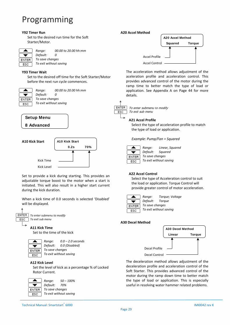
Y92 Timer Run Set to the desired run time for the Soft Starter/Motor.
Range: 00.00 to 20.00 hh:mm Default: 0 To save changes To exit without saving
Y93 Timer Wait Set to the desired off time for the Soft Starter/Motor before the next run cycle commences.
Range: 00.00 to 20.00 hh:mm Default: 0 To save changes To exit without saving
A10 Kick Start
Set to provide a kick during starting. This provides an adjustable torque boost to the motor when a start is initiated. This will also result in a higher start current during the kick duration.
When a kick time of 0.0 seconds is selected ‘Disabled’ will be displayed.
To enter submenu to modify To exit sub menu
A11 Kick Time Set to the time of the kick
Range: 0.0 – 2.0 seconds Default: 0.0 (Disabled) To save changes To exit without saving
A12 Kick Level Set the level of kick as a percentage % of Locked Rotor Current.
Range: 50 – 100% Default: 70% To save changes To exit without saving
A20 Accel Method
The acceleration method allows adjustment of the aceleration profile and acceleration control. This provides advanced control of the motor during the ramp time to better match the type of load or application. See Appendix A on Page 44 for more details.
To enter submenu to modify To exit sub menu
A21 Accel Profile Select the type of acceleration profile to match the type of load or application. Example: Pump/Fan = Squared
Range: Linear, Squared Default: Squared To save changes To exit without saving
A22 Accel Control Select the type of Acceleration control to suit the load or application. Torque Control will provide greater control of motor acceleration.
Range: Torque; Voltage Default: Torque To save changes To exit without saving
A30 Decel Method
The deceleration method allows adjustment of the deceleration profile and acceleration control of the Soft Starter. This provides advanced control of the motor during the ramp down time to better match the type of load or application. This is especially useful in resolving water hammer related problems.
Setup Menu
8 Advanced
Kick Time
Kick Level
A10 Kick Start
0.2s 70%
Accel Profile
Accel Control
A20 Accel Method
Squared Torque
Decel Profile
Decel Control
A30 Decel Method
Linear Torque
Programming
Technical Manual: Smartstart® 6000 IMI0042 rev K Page 30
To save changes To exit without saving
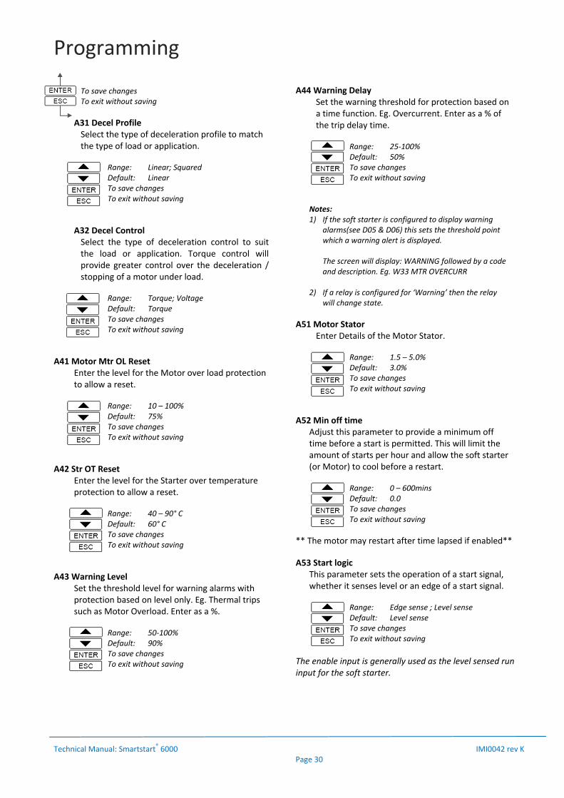
A31 Decel Profile Select the type of deceleration profile to match the type of load or application.
Range: Linear; Squared Default: Linear To save changes To exit without saving
A32 Decel Control Select the type of deceleration control to suit the load or application. Torque control will provide greater control over the deceleration / stopping of a motor under load.
Range: Torque; Voltage Default: Torque To save changes To exit without saving
A41 Motor Mtr OL Reset Enter the level for the Motor over load protection to allow a reset.
Range: 10 – 100% Default: 75% To save changes To exit without saving
A42 Str OT Reset Enter the level for the Starter over temperature protection to allow a reset.
Range: 40 – 90° C Default: 60° C To save changes To exit without saving
A43 Warning Level Set the threshold level for warning alarms with protection based on level only. Eg. Thermal trips such as Motor Overload. Enter as a %.
Range: 50‐100% Default: 90% To save changes To exit without saving
A44 Warning Delay Set the warning threshold for protection based on a time function. Eg. Overcurrent. Enter as a % of the trip delay time.
Range: 25‐100% Default: 50% To save changes To exit without saving
Notes: 1) If the soft starter is configured to display warning
alarms(see D05 & D06) this sets the threshold point which a warning alert is displayed.
The screen will display: WARNING followed by a code and description. Eg. W33 MTR OVERCURR
2) If a relay is configured for ‘Warning’ then the relay
will change state.
A51 Motor Stator Enter Details of the Motor Stator.
Range: 1.5 – 5.0% Default: 3.0% To save changes To exit without saving
A52 Min off time Adjust this parameter to provide a minimum off time before a start is permitted. This will limit the amount of starts per hour and allow the soft starter (or Motor) to cool before a restart.
Range: 0 – 600mins Default: 0.0 To save changes To exit without saving
** The motor may restart after time lapsed if enabled**
A53 Start logic This parameter sets the operation of a start signal, whether it senses level or an edge of a start signal.
Range: Edge sense ; Level sense Default: Level sense To save changes To exit without saving
The enable input is generally used as the level sensed run input for the soft starter.
Programming
Technical Manual: Smartstart® 6000 IMI0042 rev K Page 31
An optional ‘Start’ function is also selectable as a digital input. This is a latching input, which is unlatched by a stop control input, deactivating the enable input or a trip. Level Sense: The default setting when using the enable input to run the soft starter. For ‘power‐up’ start with line supply to function, ‘level sense’ must be selected. Also used for 2 wire run/stop control using the digital input ‘Start’ and enable input. (may be used in conjunction with the ‘stop’ or ‘coast’ input).The start signal must be present until motor commences start. Edge Sense: Will only start with an edge trigger. This is the recommended setting for 3 wire start/stop control. May also be used to prevent an unexpected start, if ‘stop/coast’ is restored and enable/start input signal remains active. Refer to page 14 more wiring configuration. Refer to pages 26‐27 for selection of digital inputs and also page 34 for description of the digital input variables.. A61 Try Tiny Motor
Allows a test of the starter using a small test motor or motor smaller than the starter is rated.
Range: Enable/Disable Default: Disable To save changes To exit without saving
The Smartstart®6000 will trip on motor loss if motor current falls below 15% of the entered FLC. This creates a problem for workshop testing or fault finding. If ‘Try Tiny Motor’ is enabled a start is allowed which ignores this protection. When the control supply is removed this automatically resets to ’disabled’.
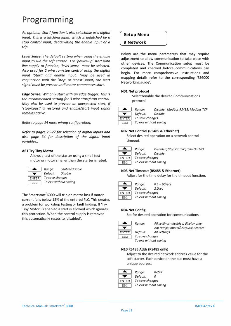
Below are the menu parameters that may require adjustment to allow communication to take place with other devices. The Communication setup must be completed and checked before communications can begin. For more comprehensive instructions and mapping details refer to the corresponding ‘SS6000 Networking guide’.
N01 Net protocol Select/enable the desired Communications protocol.
Range: Disable; Modbus RS485: Modbus TCP Default: Disable To save changes To exit without saving
N02 Net Control (RS485 & Ethernet) Select desired operation on a network control timeout.
Range: Disabled; Stop On T/O; Trip On T/O Default: Disable To save changes To exit without saving
N03 Net Timeout (RS485 & Ethernet) Adjust for the time delay for the timeout function.
Range: 0.1 – 60secs Default: 2.0sec To save changes To exit without saving
N04 Net Config Set for desired operation for communications .
Range: All settings; disabled, display only; Adj ramps; Inputs/Outputs; Restart Default: All Settings To save changes To exit without saving
N10 RS485 Addr (RS485 only) Adjust to the desired network address value for the soft starter. Each device on the bus must have a unique address.
Range: 0‐247 Default: 0 To save changes To exit without saving
Setup Menu
9 Network
Programming
Technical Manual: Smartstart® 6000 IMI0042 rev K Page 32
N11 RS485 Speed (RS485 only) Adjust to the required baud rate.
Range: 4800,9600,19k2,38k4 Default: 19k2 To save changes To exit without saving
N12 RS485 Format (RS485 only) Select the correct protocol format.
Range: 8o1, 8n1, 8n2, 8e1 Default: 8e1 To save changes To exit without saving
N20 IP Address (Ethernet Only) Enter the IP address in format shown
N21 IP Address 1 (Ethernet Only)
Range: 0 ‐255 Default: 0 To save changes To exit without saving
N22 IP Address 2 (Ethernet Only)
Range: 0 ‐255 Default: 0 To save changes To exit without saving
N23 IP Address 3 (Ethernet Only)
Range: 0 ‐255 Default: 0 To save changes To exit without saving
N24 IP Address 4 (Ethernet Only)
Range: 0 ‐255 Default: 0 To save changes To exit without saving
N25 IP Mask Bits (Ethernet Only)
Range: /2 ‐ /30 Default: /24 To save changes To exit without saving
To clear/reset any of the following a confirmation code is required: 1 Reset Trip 2 ClrTrip Log 3 Clr Mtr OL 4 Clr Counters 5 Clr Meters 6 Copy Par1 to Par2 7 Restore Defaults The Confirmation Code is: 1470
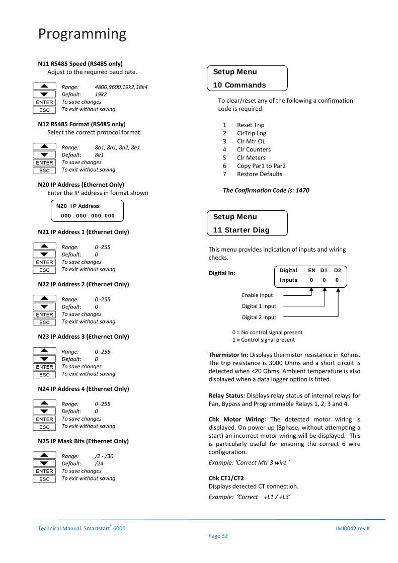
This menu provides indication of inputs and wiring checks.
Digital In:
0 = No control signal present 1 = Control signal present
Thermistor In: Displays thermistor resistance in Kohms. The trip resistance is 3000 Ohms and a short circuit is detected when <20 Ohms. Ambient temperature is also displayed when a data logger option is fitted. Relay Status: Displays relay status of internal relays for Fan, Bypass and Programmable Relays 1, 2, 3 and 4.
Chk Motor Wiring: The detected motor wiring is displayed. On power up (3phase, without attempting a start) an incorrect motor wiring will be displayed. This is particularly useful for ensuring the correct 6 wire configuration.
Example: ‘Correct Mtr 3 wire ‘
Chk CT1/CT2 Displays detected CT connection.
Example: ‘Correct +L1 / +L3’
Setup Menu
10 Commands
Setup Menu
11 Starter Diag
Digital EN D1 D2
Inputs 0 0 0
Enable Input
Digital 1 Input
Digital 2 Input
N20 IP Address
000 . 000 . 000. 000
Programming
Technical Manual: Smartstart® 6000 IMI0042 rev K Page 33
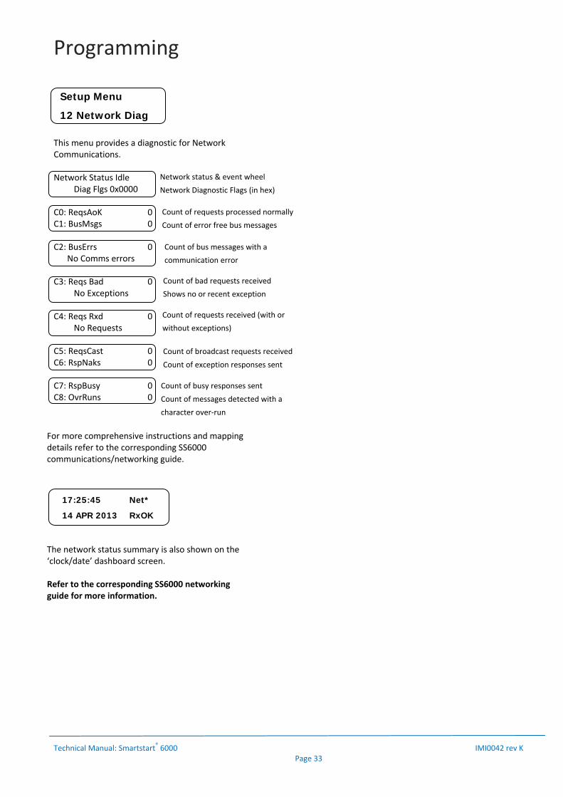
This menu provides a diagnostic for Network Communications. Network Status Idle Diag Flgs 0x0000 C0: ReqsAoK 0 C1: BusMsgs 0 C2: BusErrs 0 No Comms errors C3: Reqs Bad 0 No Exceptions C4: Reqs Rxd 0 No Requests C5: ReqsCast 0 C6: RspNaks 0 C7: RspBusy 0 C8: OvrRuns 0
For more comprehensive instructions and mapping details refer to the corresponding SS6000 communications/networking guide.
The network status summary is also shown on the ‘clock/date’ dashboard screen. Refer to the corresponding SS6000 networking guide for more information.
Setup Menu
12 Network Diag
17:25:45 Net*
14 APR 2013 RxOK
Network status & event wheel
Network Diagnostic Flags (in hex)
Count of requests processed normally
Count of error free bus messages
Count of bus messages with a
communication error
Count of bad requests received
Shows no or recent exception
Count of requests received (with or
without exceptions)
Count of broadcast requests received
Count of exception responses sent
Count of busy responses sent
Count of messages detected with a
character over‐run

Programming
Technical Manual: Smartstart® 6000 IMI0042 rev K Page 34
Table1:OutputRelayFunctionality
Table2:AnalogueOutputFunctionality
Table3:DigitalInputFunctionality
Relay Function
Selection: Description
Line Ctrl Control for Line Contactor
Bypass Ctrl Control for Bypass Contactor
Accel Ramp Starter in acceleration ramp mode
Decel Ramp Starter in deceleration ramp mode
Ramping Starter in Ramp Mode
Up to Speed motor is up to speed
Motor On Motor is running
Trip Alarm A trip alarm is active
Mtr Loss Output phase(s) open circuit/motor isolated
Freq Error Supply frequency range exceeded
Bypass FLT Bypass contactor failed
STR OL Trip Starter reached overload level
Mtr OL Trip Motor reached overload level
Mtr OT Trip Motor thermistor/switch trip active
Ph Rotation Rotation trip active
Dig In Trip Digital input trip active
Over time Over time trip active
Volt Imbal Voltage Imbalance trip active
Curr Imbal Current imbalance trip active
Under Current Under current trip active
Over Current Over Current trip active
Under Torque Under Torque trip active
Over Torque Over Torque trip active
Warning Alarm A warning alarm is active
TOL Warning Motor Overload warning alarm
Regen. Mode Soft starter is operating in regeneration mode
AR Pending Waiting for restart (time)
AR Lockout Restarts exhausted – starter tripped
ESO Proof In ESO and current detected
Timer Relay Timer function is active
Fan Control Fan is ON
Test (ON) Turns relay on
Brake Fault Fault with external mechanical Brake
Analogue Output
Selection: Description
Mtr Torque Estimated torque produced in motor
Mtr Thermal Estimated Motor temperature of over load
STR thermal Soft Starter temperature
Active power Power consumed kW
Power Factor Power Factor
Mtr Current Motor Current
Test (100%) Maximum output
Digital Input
Selection: Description
Reset
Attempts to reset a Smartstart trip/fault condition. Motor may start immediately on successful reset. A delay can also be configured.
Trip Trips the Smartstart after a configurable delay. Ideal for external pressure/flow switch.
Start
Enable this function where 3 wire start/stop control is required. The start request is latched once the motor starts. Use the enable or ‘stop’ input to a N/C stop button, to unlatch. Edge or level sense may be used.
Stop Initiates a motor stop with the configured decel profile. A delay may be incorporated.
Coast Forces a free wheel stop from any operating state. Optional delay
Local Forces local control and disables network control
Par2 Activates the Par2 start parameters for the next ramp (Accel or Decel).
ESO
Essential Services Override: This feature is designed for systems that must operate in the event of an emergency (eg. Fire Mode). ESO overrides most protection and input conditions to run the motor.
Brake ON Feedback from switch that indicates the position of an external mechanical Brake See Page 35 for more details.
Programming
Technical Manual: Smartstart® 6000 IMI0042 rev K Page 35
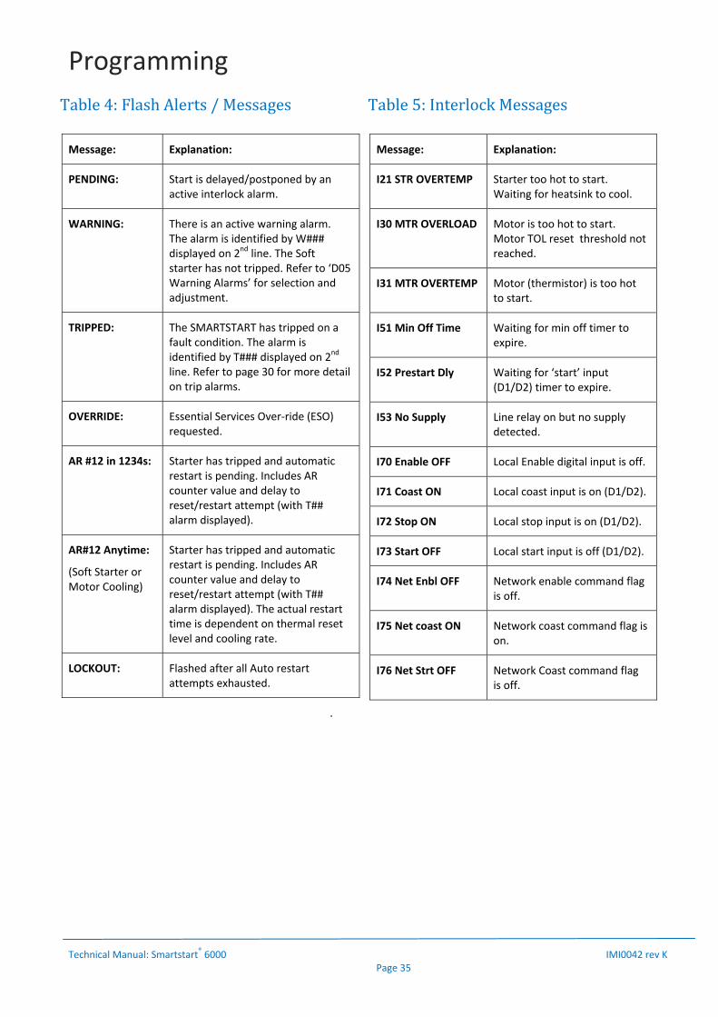
Table4:FlashAlerts/MessagesMessage: Explanation:
PENDING: Start is delayed/postponed by an active interlock alarm.
WARNING: There is an active warning alarm. The alarm is identified by W### displayed on 2nd line. The Soft starter has not tripped. Refer to ‘D05 Warning Alarms’ for selection and adjustment.
TRIPPED: The SMARTSTART has tripped on a fault condition. The alarm is identified by T### displayed on 2nd line. Refer to page 30 for more detail on trip alarms.
OVERRIDE: Essential Services Over‐ride (ESO) requested.
AR #12 in 1234s: Starter has tripped and automatic restart is pending. Includes AR counter value and delay to reset/restart attempt (with T## alarm displayed).
AR#12 Anytime:
(Soft Starter or Motor Cooling)
Starter has tripped and automatic restart is pending. Includes AR counter value and delay to reset/restart attempt (with T## alarm displayed). The actual restart time is dependent on thermal reset level and cooling rate.
LOCKOUT: Flashed after all Auto restart attempts exhausted.
.
Table5:InterlockMessagesMessage: Explanation:
I21 STR OVERTEMP Starter too hot to start. Waiting for heatsink to cool.
I30 MTR OVERLOAD Motor is too hot to start. Motor TOL reset threshold not reached.
I31 MTR OVERTEMP Motor (thermistor) is too hot to start.
I51 Min Off Time Waiting for min off timer to expire.
I52 Prestart Dly Waiting for ‘start’ input (D1/D2) timer to expire.
I53 No Supply Line relay on but no supply detected.
I70 Enable OFF Local Enable digital input is off.
I71 Coast ON Local coast input is on (D1/D2).
I72 Stop ON Local stop input is on (D1/D2).
I73 Start OFF Local start input is off (D1/D2).
I74 Net Enbl OFF Network enable command flag is off.
I75 Net coast ON Network coast command flag is on.
I76 Net Strt OFF Network Coast command flag is off.
Programming
Technical Manual: Smartstart® 6000 IMI0042 rev K Page 36
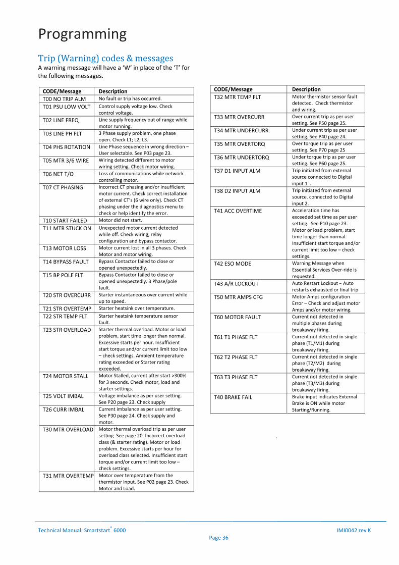
Trip(Warning)codes&messagesA warning message will have a ‘W’ in place of the ‘T’ for the following messages.
CODE/Message Description
T00 NO TRIP ALM No fault or trip has occurred.
T01 PSU LOW VOLT Control supply voltage low. Check control voltage.
T02 LINE FREQ Line supply frequency out of range while motor running.
T03 LINE PH FLT 3 Phase supply problem, one phase open. Check L1; L2; L3.
T04 PHS ROTATION Line Phase sequence in wrong direction –User selectable. See P03 page 23.
T05 MTR 3/6 WIRE Wiring detected different to motor wiring setting. Check motor wiring.
T06 NET T/O Loss of communications while network controlling motor.
T07 CT PHASING Incorrect CT phasing and/or insufficient motor current. Check correct installation of external CT’s (6 wire only). Check CT phasing under the diagnostics menu to check or help identify the error.
T10 START FAILED Motor did not start.
T11 MTR STUCK ON Unexpected motor current detected while off. Check wiring, relay configuration and bypass contactor.
T13 MOTOR LOSS Motor current lost in all 3 phases. Check Motor and motor wiring.
T14 BYPASS FAULT Bypass Contactor failed to close or opened unexpectedly.
T15 BP POLE FLT Bypass Contactor failed to close or opened unexpectedly. 3 Phase/pole fault.
T20 STR OVERCURR Starter instantaneous over current while up to speed.
T21 STR OVERTEMP Starter heatsink over temperature.
T22 STR TEMP FLT Starter heatsink temperature sensor fault.
T23 STR OVERLOAD Starter thermal overload. Motor or load problem, start time longer than normal. Excessive starts per hour. Insufficient start torque and/or current limit too low – check settings. Ambient temperature rating exceeded or Starter rating exceeded.
T24 MOTOR STALL Motor Stalled, current after start >300% for 3 seconds. Check motor, load and starter settings.
T25 VOLT IMBAL Voltage imbalance as per user setting. See P20 page 23. Check supply
T26 CURR IMBAL Current imbalance as per user setting. See P30 page 24. Check supply and motor.
T30 MTR OVERLOAD Motor thermal overload trip as per user setting. See page 20. Incorrect overload class (& starter rating). Motor or load problem. Excessive starts per hour for overload class selected. Insufficient start torque and/or current limit too low – check settings.
T31 MTR OVERTEMP Motor over temperature from the thermistor input. See P02 page 23. Check Motor and Load.
CODE/Message Description
T32 MTR TEMP FLT Motor thermistor sensor fault detected. Check thermistor and wiring.
T33 MTR OVERCURR Over current trip as per user setting. See P50 page 25.
T34 MTR UNDERCURR Under current trip as per user setting. See P40 page 24.
T35 MTR OVERTORQ Over torque trip as per user setting. See P70 page 25
T36 MTR UNDERTORQ Under torque trip as per user setting. See P60 page 25.
T37 D1 INPUT ALM Trip initiated from external source connected to Digital input 1 .
T38 D2 INPUT ALM Trip initiated from external source. connected to Digital input 2.
T41 ACC OVERTIME Acceleration time has exceeded set time as per user setting. See P10 page 23. Motor or load problem, start time longer than normal. Insufficient start torque and/or current limit too low – check settings.
T42 ESO MODE Warning Message when Essential Services Over‐ride is requested.
T43 A/R LOCKOUT Auto Restart Lockout – Auto restarts exhausted or final trip
T50 MTR AMPS CFG Motor Amps configuration Error – Check and adjust motor Amps and/or motor wiring.
T60 MOTOR FAULT Current not detected in multiple phases during breakaway firing.
T61 T1 PHASE FLT Current not detected in single phase (T1/M1) during breakaway firing.
T62 T2 PHASE FLT Current not detected in single phase (T2/M2) during breakaway firing.
T63 T3 PHASE FLT Current not detected in single phase (T3/M3) during breakaway firing.
T40 BRAKE FAIL Brake input indicates External Brake is ON while motor Starting/Running.
.

Programming
Technical Manual: Smartstart® 6000 IMI0042 rev K Page 37
BrakeFailProtection: A digital input can be programmed for ‘Brake On’. This allows a voltage free contact indicating the position of a mechanical brake to the Soft Starter. The intention of this feature is for the soft starter to safely stop the motor from driving into a load with the brake applied for a period of time. indicate a ‘Brake Fail’ condition. This will provide protection of the Motor and mechanical components from damage. It is not a safety feature to provide protection should the Brake fail to operate when the motor is stopped. However, it will display a warning.
Operation:The SS6000 continuously monitors the Brake feedback via a digital Input. The digital input may be ‘Enabled’ or ‘inverted’. 1. ‘ENABLED’ = 24VDC at input when brake coil de‐
energised (Brake is ON). 2. ‘INVERTED’ = 24VDC at input when brake coil
energised (Brake OFF). A brake Trip will also occur if brake switch wiring is Open Circuit.
A “Brake ON’ input indicates to the Soft Starter that the brake is applied to the output shaft (ie. A fault when the motor is running).
A T40 BRAKE FAULT (Trip) will occur if the Brake is ON while the motor is ON. An adjustable delay allows time for the brake to lift during starting. If in Bypass mode, the trip has a fixed delay to prevent false trips and to allow the Soft starter to use the SCR’s to break any potential high locked Rotor Currents. A W40 BRAKE FAULT (Warning, no trip) will be displayed if the Brake remains OFF (lifted) after the motor turns off.
AdjustableSettings: DigIn 1 or 2 Variable
Activate the Brake Fail protection by assigning a digital input to ‘Brake On’.
Range: Trip; Reset; Start; Stop; Coast; Local; ESO; Brake On
Default: Reset To save changes To exit without saving
DigIn 1 or 2 Delay (Brake Lift Delay) Set the delay to allow time for the brake to lift on motor start (motor takes up load torque). This delay is normally set between 1 and 5 seconds.
Range: 0.0 – 300.0 seconds Default: 0.0 To save changes To exit without saving
Specification/Setting Value Description
Brake Lift Delay 0 – 300s Maximum time allowed for brake to lift on motor start. Adjustable Delay
Brake Fault Detect delay 0.2s Fixed Delay to prevent false trips due to timing of enable and brake.
Time to turn motor off 0.5s Max Bypass contactor and SCR sequencing to stop under load
Warning Delay 2s When motor is off and brake remains lifted

Specification
Technical Manual: Smartstart® 6000 IMI0042 rev K Page 38
Input Voltage: 6R series: 220 to 460Vac 6R15‐80: 380Vac to 415Vac 6V series: 600 to 1000V (+10%) Input Frequency: 50 / 60Hz +/‐ 3Hz, Auto detecting Control Supply: 24Vdc (+15%, ‐15%) 24VDC Power Supply (min. requirements):
Power Supply O/P: 24VDC Regulated Peak power requirements:
6R15‐30: 1.5 Amps (36W) 6R60‐80: 2 Amps (48W) 6R100–220/6V90: 3.0Amps (72W) 6R300–880: 4.0 Amps (96W) 6V200‐400: 4.0 Amps (96W)
These ratings allow for peak current requirements of internal fans
AC Control Supply Options Available: 240VAC: All Models 18VAC: All Models 415VAC Self Powered 6R15/30/60/80 Only
Configurations: i) 3 wire & 6 wire ii) Bypass or Continuous
6R15 to 6R80 have integral Bypass Contactor.
Duty: Light Duty: 300% for 15 secs; 10start/hr 350% for 10secs; 10start/hr Standard Duty: 300% for 30secs; 10start/hr 400% for 10 secs; 10start/hr Severe Duty: 450 for 20 secs; 5start/hr 300% for 60 secs; 5start/hr SCR PIV: Minimum 1400V (6R series) Minimum 3600V (6V series) SCR configuration: Full‐wave Dv/dt suppression: RC snubber networks Over Voltage: MOV Rated Insulation: 2Kv (6R series) EMC Class A (to AS61800 – C‐tick) Current Feedback Current transformer in circuit at all times.
Torque controlled Ramp or voltage ramp, with current limit override
Standards Compliance AS31800 C‐tick; AS3947.4.2, IEC60947‐4‐2
Environment: Enclosure protection: IP00 – IP20 Operating Temp. 0 to 55°C (derate by 1% / °C >40°C) Cooling: Temperature controlled forced ventilated Maximum Altitude: 1000m without derating Operating position: Vertical Pollution: Degree 3 conforming to IEC947‐4‐2
Inputs: Digital Inputs: 24Vdc Logic Function: 2x Programmable inputs 1x Enable Input Thermistor: Thermistor or NC switch PTC type, Trip Resistance 3000Ohms, <20ohms detected as Short Circuit. Outputs: Digital Output: 4 Programmable Relays Contact Rating: 5A 250Vac; 5A 30VDC resistive Analogue Output: 1x Programmable Output Signal: 0‐10V, 0‐5V, 4‐20mA Communications: Modbus RS485 (Standard) Ethernet (Modbus) Option Protection: Motor Overload Adjustable; Class 10, 10A, 20, 25, 30 type R1,
total memory function SCR Over temp. Heat sink temperature SCR protection: Current & thermal modelling Under Current Adjustable level and trip time Over Current Adjustable level and trip time Under Torque: Adjustable level and trip time Over Torque: Adjustable level and trip time Motor Stalled 300% for 3 seconds (run mode only) Current limit Adjustable Starter Overload Current & thermal modelling O/P Short Circuit Semiconductor fuses (optional) Voltage imbalance Input voltage imbalance Current Imbalance Input & output current imbalance Bypass failure No bypass after ramp time or during run
mode SCR fault Open or Short circuit SCR Acc over time Accel time exceeds set time Phase reversal Phase rotation inhibit Motor Loss Motor or output open cct CT fault Fault with CT’s Line Freq/Phase Problem with supply Network Timeout Network Fault Remote Input Forced trip from external source Human Interface Module (HIM): Type: Local or remote mountable (IP66) Display: Backlit LCD (Blue) , English Menu: Coded & English Menu Protected: Selectable user access code Cable type: Ribbon or Cat‐5 Essential Services Over‐ride (ESO): Selectable Digital input with 24Vdc logic. Battery: Type: CR1220

ThermalProtection
Technical Manual: Smartstart® 6000 IMI0042 rev K Page 39
Starter Thermal Protection: Thermal protection of the soft starter is provided by a temperature sensor located on the heatsink and by calculating the temperature of the thyristor junction with sophisticated modeling of the specific devices used. Fans are powered by 24VDC supply and thermally controlled when the heatsink temperature exceeds 40°C and whilst the motor is ramping. Motor thermal Protection The Smartstart®6000 provides thermal protection of the motor by providing a thermistor input and also a programmable motor overload protection feature. The starter continuously monitors the current and calculates the temperature rise of the motor based on the motor data provided. The standard IEC60947‐4‐2 defines the protection classes giving the starting capacities of the motor (warm or cold) without thermal trips. The thermal protection displayed by the starter corresponds to the thermal time constant:
An overload trip will occur and stop the motor, if the motor exceeds the critical temperature rise threshold of 125%
This feature has a memory function based on the thermal capacity and may not allow a start if the temperature rise is too high.
The thermal state continues to calculate even when the starter is off and powered down. Simply by turning power off and back on will not reset the thermal state.
Motor thermistor Protection The Smartstart®6000 provides an input for a thermistor or normally closed switch. Thermistor / PTC probes integrated in the motor to measure its temperature can be connected to the thermistor input terminals. This input has a trip resistance of 3000ohms and a resistance of 20ohms or less will be detected as a short circuit. Alternatively, a normally closed thermal switch may be used which open circuits at a specific temperature.
Motor thermal Protection: Cold Curves
Hot Curves
SS6000 Motor Thermal Overload Curves - Cold
1.000
10.000
100.000
1000.000
10000.000
0 1 2 3 4 5 6 7 8
X FLC
Tri
p T
ime
(s)
Class 30 Cold
Class 20 Cold
Class 10 Cold
Class 10A Cold
Class 2 Cold
SS6000 Motor Thermal Overload Curves - Warm
0.100
1.000
10.000
100.000
1000.000
0 1 2 3 4 5 6 7 8
X FLC
Tri
p T
ime
(s)
Class 30 Warm
Class 20 Warm
Class 10 Warm
Class 10A Warm
Class 2 Warm
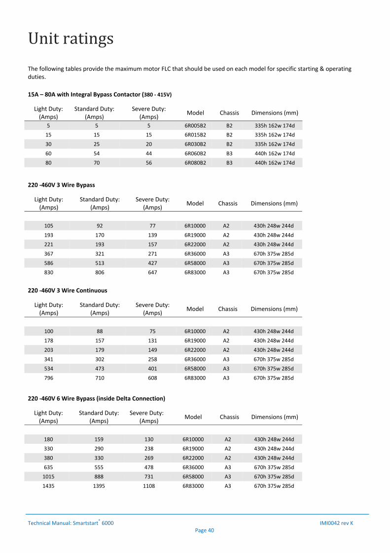
Unitratings
Technical Manual: Smartstart® 6000 IMI0042 rev K Page 40
The following tables provide the maximum motor FLC that should be used on each model for specific starting & operating duties.
15A – 80A with Integral Bypass Contactor (380 ‐ 415V)
Light Duty: (Amps)
Standard Duty: (Amps)
Severe Duty:(Amps)
Model Chassis Dimensions (mm)
5 5 5 6R005B2 B2 335h 162w 174d
15 15 15 6R015B2 B2 335h 162w 174d
30 25 20 6R030B2 B2 335h 162w 174d
60 54 44 6R060B2 B3 440h 162w 174d
80 70 56 6R080B2 B3 440h 162w 174d
220 ‐460V 3 Wire Bypass
Light Duty: (Amps)
Standard Duty:(Amps)
Severe Duty:(Amps)
Model Chassis Dimensions (mm)
105 92 77 6R10000 A2 430h 248w 244d
193 170 139 6R19000 A2 430h 248w 244d
221 193 157 6R22000 A2 430h 248w 244d
367 321 271 6R36000 A3 670h 375w 285d
586 513 427 6R58000 A3 670h 375w 285d
830 806 647 6R83000 A3 670h 375w 285d
220 ‐460V 3 Wire Continuous
220 ‐460V 6 Wire Bypass (inside Delta Connection)
Light Duty: (Amps)
Standard Duty:(Amps)
Severe Duty:(Amps)
Model Chassis Dimensions (mm)
180 159 130 6R10000 A2 430h 248w 244d
330 290 238 6R19000 A2 430h 248w 244d
380 330 269 6R22000 A2 430h 248w 244d
635 555 478 6R36000 A3 670h 375w 285d
1015 888 731 6R58000 A3 670h 375w 285d
1435 1395 1108 6R83000 A3 670h 375w 285d
Light Duty: (Amps)
Standard Duty:(Amps)
Severe Duty:(Amps)
Model Chassis Dimensions (mm)
100 88 75 6R10000 A2 430h 248w 244d
178 157 131 6R19000 A2 430h 248w 244d
203 179 149 6R22000 A2 430h 248w 244d
341 302 258 6R36000 A3 670h 375w 285d
534 473 401 6R58000 A3 670h 375w 285d
796 710 608 6R83000 A3 670h 375w 285d
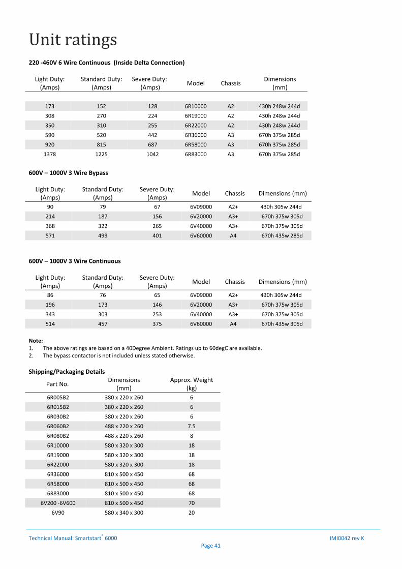
Unitratings
Technical Manual: Smartstart® 6000 IMI0042 rev K Page 41
220 ‐460V 6 Wire Continuous (Inside Delta Connection) Light Duty: (Amps)
Standard Duty:(Amps)
Severe Duty:(Amps)
Model Chassis Dimensions
(mm)
173 152 128 6R10000 A2 430h 248w 244d
308 270 224 6R19000 A2 430h 248w 244d
350 310 255 6R22000 A2 430h 248w 244d
590 520 442 6R36000 A3 670h 375w 285d
920 815 687 6R58000 A3 670h 375w 285d
1378 1225 1042 6R83000 A3 670h 375w 285d
600V – 1000V 3 Wire Bypass Light Duty: (Amps)
Standard Duty:(Amps)
Severe Duty:(Amps)
Model Chassis Dimensions (mm)
90 79 67 6V09000 A2+ 430h 305w 244d
214 187 156 6V20000 A3+ 670h 375w 305d
368 322 265 6V40000 A3+ 670h 375w 305d
571 499 401 6V60000 A4 670h 435w 285d
600V – 1000V 3 Wire Continuous Light Duty: (Amps)
Standard Duty:(Amps)
Severe Duty:(Amps)
Model Chassis Dimensions (mm)
86 76 65 6V09000 A2+ 430h 305w 244d
196 173 146 6V20000 A3+ 670h 375w 305d
343 303 253 6V40000 A3+ 670h 375w 305d
514 457 375 6V60000 A4 670h 435w 305d
Note: 1. The above ratings are based on a 40Degree Ambient. Ratings up to 60degC are available. 2. The bypass contactor is not included unless stated otherwise.
Shipping/Packaging Details
Part No. Dimensions
(mm) Approx. Weight
(kg)
6R005B2 380 x 220 x 260 6
6R015B2 380 x 220 x 260 6
6R030B2 380 x 220 x 260 6
6R060B2 488 x 220 x 260 7.5
6R080B2 488 x 220 x 260 8
6R10000 580 x 320 x 300 18
6R19000 580 x 320 x 300 18
6R22000 580 x 320 x 300 18
6R36000 810 x 500 x 450 68
6R58000 810 x 500 x 450 68
6R83000 810 x 500 x 450 68
6V200 ‐6V600 810 x 500 x 450 70
6V90 580 x 340 x 300 20
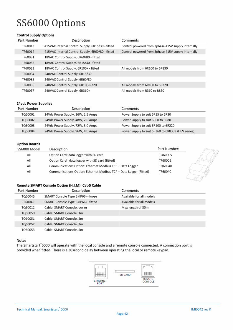
SS6000Options
Technical Manual: Smartstart
® 6000 IMI0042 rev K Page 42
Control Supply Options
Part Number Description Comments
TF60013 415VAC Internal Control Supply, 6R15/30 ‐ fitted Control powered from 3phase 415V supply internally
TF60014 415VAC Internal Control Supply, 6R60/80 ‐ fitted Control powered from 3phase 415V supply internally
TF60031 18VAC Control Supply, 6R60/80 ‐ fitted
TF60032 18VAC Control Supply, 6R15/30 ‐ fitted
TF60033 18VAC Control Supply, 6R100+ ‐ fitted All models from 6R100 to 6R830
TF60034 240VAC Control Supply, 6R15/30
TF60035 240VAC Control Supply, 6R60/80
TF60036 240VAC Control Supply, 6R100‐R220 All models from 6R100 to 6R220
TF60037 240VAC Control Supply, 6R360+ All models from R360 to R830
24vdc Power Supplies
Part Number Description Comments
TQ60001 24Vdc Power Supply, 36W, 1.5 Amps Power Supply to suit 6R15 to 6R30
TQ60002 24Vdc Power Supply, 48W, 2.0 Amps Power Supply to suit 6R60 to 6R80
TQ60003 24Vdc Power Supply, 72W, 3.0 Amps Power Supply to suit 6R100 to 6R220
TQ60004 24Vdc Power Supply, 96W, 4.0 Amps Power Supply to suit 6R360 to 6R830 ( & 6V series)
Option Boards
SS6000 Model Description Part Number:
All Option Card: data logger with SD card TQ60005
All Option Card : data logger with SD card (fitted) TF60005
All Communications Option: Ethernet Modbus TCP + Data Logger TQ60040
All Communications Option: Ethernet Modbus TCP + Data Logger (Fitted) TF60040
Remote SMART Console Option (H.I.M): Cat‐5 Cable
Part Number Description Comments
TQ60045 SMART Console Type B (IP66) ‐ loose Available for all models
TF60045 SMART Console Type B (IP66) ‐ fitted Available for all models
TQ60012 Cable: SMART Console, per m Max length of 30m
TQ60050 Cable: SMART Console, 1m
TQ60051 Cable: SMART Console, 2m
TQ60052 Cable: SMART Console, 3m
TQ60053 Cable: SMART Console, 5m
Note: The Smartstart®6000 will operate with the local console and a remote console connected. A connection port is provided when fitted. There is a 30second delay between operating the local or remote keypad.
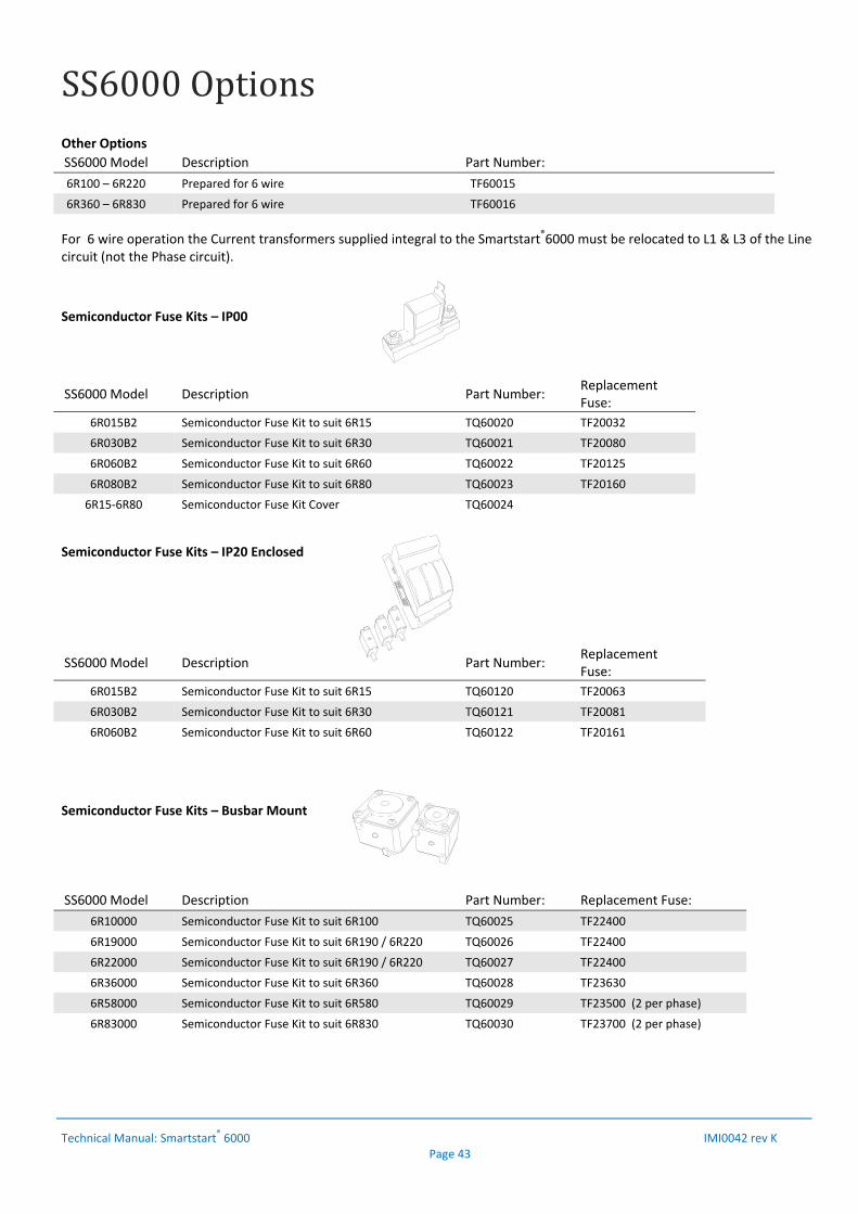
SS6000Options
Technical Manual: Smartstart
® 6000 IMI0042 rev K Page 43
Other Options
SS6000 Model Description Part Number:
6R100 – 6R220 Prepared for 6 wire TF60015
6R360 – 6R830 Prepared for 6 wire TF60016
For 6 wire operation the Current transformers supplied integral to the Smartstart®6000 must be relocated to L1 & L3 of the Line circuit (not the Phase circuit).
Semiconductor Fuse Kits – IP00
SS6000 Model Description Part Number: Replacement Fuse:
6R015B2 Semiconductor Fuse Kit to suit 6R15 TQ60020 TF20032
6R030B2 Semiconductor Fuse Kit to suit 6R30 TQ60021 TF20080
6R060B2 Semiconductor Fuse Kit to suit 6R60 TQ60022 TF20125
6R080B2 Semiconductor Fuse Kit to suit 6R80 TQ60023 TF20160
6R15‐6R80 Semiconductor Fuse Kit Cover TQ60024
Semiconductor Fuse Kits – IP20 Enclosed
SS6000 Model Description Part Number: Replacement Fuse:
6R015B2 Semiconductor Fuse Kit to suit 6R15 TQ60120 TF20063
6R030B2 Semiconductor Fuse Kit to suit 6R30 TQ60121 TF20081
6R060B2 Semiconductor Fuse Kit to suit 6R60 TQ60122 TF20161
Semiconductor Fuse Kits – Busbar Mount
SS6000 Model Description Part Number: Replacement Fuse:
6R10000 Semiconductor Fuse Kit to suit 6R100 TQ60025 TF22400
6R19000 Semiconductor Fuse Kit to suit 6R190 / 6R220 TQ60026 TF22400
6R22000 Semiconductor Fuse Kit to suit 6R190 / 6R220 TQ60027 TF22400
6R36000 Semiconductor Fuse Kit to suit 6R360 TQ60028 TF23630
6R58000 Semiconductor Fuse Kit to suit 6R580 TQ60029 TF23500 (2 per phase)
6R83000 Semiconductor Fuse Kit to suit 6R830 TQ60030 TF23700 (2 per phase)

AppendixAZENERSMART‐TORQ‐TorqueControlSystem
Technical Manual: Smartstart® 6000 IMI0042 rev K Page 44
There are several methods available to soft start a motor. The more traditional methods are Direct‐on‐line, Star/Delta, Auto transformer and Primary resistance starters. The more sophisticated methods also provide a soft stop and include Soft Starters and Variable Speed drives (VSD’s). VSD’s can provide a better soft start with significantly lower starting currents and many other benefits including energy savings. However, a Soft Starter may provide a more economical solution to motor starting over the life of the motor. Soft Starters provide the following benefits:
1. Reduced stresses and wear on the mechanics of the system 2. Reduced starting currents 3. Minimise voltage dips on the supply 4. Lowered Peak demand charges 5. Eliminate belt slippage on fans 6. Smooth acceleration of motor / load
The conventional voltage ramp Soft Starter is a reduced voltage starter and is similar to the traditional methods mentioned above. The problem with voltage ramp soft starters is a non linear acceleration of the motor. This is very noticeable on a pump type load where there is much higher acceleration torque available at the beginning of the start. The diagram below shows the variation in acceleration torque available for both a Direct on line (full voltage) and the voltage ramp type soft start. ‘SMART‐TORQ®’ is a Torque Control System developed by Zener to overcome this problem with greater control over the acceleration torque in the motor. The torque is controlled in a manner which suits the type of load to achieve a linear acceleration in motor shaft speed. This control system is also active during the deceleration phase, providing a soft stop where the motor decelerates at a constant rate. This can be used to overcome water hammer problems associated with the closing or slamming of check valves. ZENER SMART‐TORQ Key Benefits:
1. A true linear acceleration of the load and motor for variable & constant torque loads.
2. Reduced stresses and wear on the mechanics of the system. 3. Ramp profiling to better match type of load such as variable torque
loads. Better control of pumps and fans. 4. Torque Control available in Accel & Decel Modes and 3wire or 6wire
motor configuration. 5. Eliminate water hammer problems. 6. Reduced peak current draw, especially at motor pull‐in/pull‐out
operating points. 7. Reduced heating in motor at low speeds. 8. No instability due to changing power factor. Closed loop system to
monitor and react to changing power factor. 9. No instability due to slot ripple in 3 wire and 6 wire operation. 10. Better control of deceleration through closed loop torque control
system. 11. No external speed sensor required to produce superior performance.
The rate of acceleration is dependent on the additional torque (Acceleration Torque) available in the motor. Thus, we can achieve a constant or linear rate of Acceleration by providing ‘constant’ acceleration torque to the motor.
Since the torque required by the load may not be linear, the torque delivered by the soft starter must match that of the load. To achieve this, the torque developed in the motor must be the sum of the ‘acceleration torque’ and the load torque at a specific speed. Below illustrates the constant acceleration torque applied for different load types; 1) Constant Torque type Load (eg. Conveyor) 2) Variable Torque type Load (eg. Pump/Fan) How is this achieved ? The SMARTSTART® 6000 continually monitors start variables such as motor current, voltage and power factor to determine the input electrical power. From the motor parameters, the IR & magnetic losses are used to calculate the Air Gap Power (ie. the power transmitted to the motor shaft). With an instantaneous value of shaft power the instantaneous torque can be determined. With this information we can vary the thyristor conduction to achieve the desired torque. The torque is varied to follow a specific curve, based on the initial torque setting, the final torque setting and the profile selected. The end result is equal acceleration torque over the ramp period to provide a linear acceleration in motor shaft speed. The profile is user adjustable allowing for non‐linear torques if required to other or unusual types of loads.
Summary. The ‘SMART‐TORQ®’ Torque Control System provides smoother starting & stopping, allowing ramp profiling to produce a linear acceleration and deceleration of the motor speed. There are many benefits with variable torque loads such a pumps. A linear acceleration and deceleration provides better control to eliminate water hammer problems. The SMARTSTART® 6000 combines this superior torque control system with a robust design to suit all types of loads and applications. All models include substantial heatsink mass with temperature controlled force ventilation to accommodate the more severe (heavy) duty applications.
Total Torque
Load Torque
Speed
Torque
Acceleration Torque
Load Torque
Speed
Torque
Acceleration Torque
Total Torque
100%
100%
Load Torque
Speed
LRT
DOL (full Voltage) Torque
100%
FLT (100%)
Voltage Ramp Torque
Acceleration Torque

AppendixAIndicativeparametersfordifferentloadtypes
Technical Manual: Smartstart® 6000 IMI0042 rev K Page 45
1. Pump (3 wire/Bypass with No Soft Stop)
Factory defaults are intended for general pumping/fan application with no Soft Stop. Enter motor parameters as per motor nameplate.
2. Submersible Pump (3 wire/Bypass with No Soft Stop)
Factory defaults are intended for general pumping application with no Soft Stop. The acceleration time needs to be reduced to 3secs or as per pump/motor manufacturers recommendations. Enter motor parameters as per motor nameplate.
Ref Page Parameter Setting (factory Default)
C11 22 Accel time 3sec (10s)
M01 21 Motor Amps ‘Nameplate Motor FLC’
M02 21 Motor Volts ‘Nameplate Motor Volts’
M03 21 Motor PF ‘Nameplate Motor PF’
3. Pump :(3 wire/Bypass with Soft Stop)
Factory defaults are intended for general pumping application with no Soft Stop. Enter motor parameters as per motor nameplate. Adjust the ‘Release Torque’ and ‘Decel time’ to achieve the required soft stop.
Ref Page Parameter Setting (factory Default)
C21 22 Decel time *15sec (0s)
C22 22 Release Torque *2% (2%)
M01 21 Motor Amps ‘Nameplate Motor FLC’
M02 21 Motor Volts ‘Nameplate Motor Volts’
M03 21 Motor PF ‘Nameplate Motor PF’
4. Fan :(3 wire/Bypass)
Factory defaults are intended for general pumping application which is similar to that required for a fan. However, the Accel time may need to be increased to allow for longer ramp times of high inertia fans. The Motor Overload Class may also need to be increased with the extended ramp of high inertia fans. Enter motor parameters as per motor nameplate.
Ref Page Parameter Setting (factory Default)
C11 22 Accel time 15+ (10s)
P01 23 Motor Overload Class 10 /Class 20 (10)
M01 21 Motor Amps ‘Nameplate Motor FLC’
M02 21 Motor Volts ‘Nameplate Motor Volts’
M03 21 Motor PF ‘Nameplate Motor PF’
5. Conveyor: (3 wire/Bypass)
Factory defaults are preset for a variable torque load. The Torque settings will need to be adjusted for a constant torque type load. Enter motor parameters as per motor nameplate.
Ref Page Parameter Setting (factory Default)
C12 22 Start Torque 80% (30%)
C13 22 Final Torque 150% (130%)
A21 29 Accel profile Linear (Squared)
P01 23 Motor Overload Class 20 (10)
M01 21 Motor Amps ‘Nameplate Motor FLC’
M02 21 Motor Volts ‘Nameplate Motor Volts’
M03 21 Motor PF ‘Nameplate Motor PF’
6. Compressor: (3 wire/Bypass)
Factory defaults are preset for a variable torque load. The Torque settings will need to be adjusted for a constant torque type load. Enter motor parameters as per motor nameplate.
Ref Page Parameter Setting (factory Default)
C12 22 Start Torque 60% (30%)
C13 222 Final Torque 130% (130%)
A21 29 Accel profile Linear (Squared)
P01 23 Motor Overload Class 20 (10)
M01 21 Motor Amps ‘Nameplate Motor FLC’
M02 21 Motor Volts ‘Nameplate Motor Volts’
M03 21 Motor PF ‘Nameplate Motor PF’
7. Suggested Protection Settings
Below are suggested settings to provide additional protection of the motor and load. These are general settings and should be further tuned to suit the application and load conditions.
Ref Page Parameter Setting (factory Default)
P01 23 Motor Overload Class 10a/10/20 (10)
P02 23 Motor O/Temp Thermistor (Disabled)
P03 23 Phase Rotation 1‐2‐3 (Disabled)
P10 23 Accel O/Time Trip / 5s (Disabled)
P20 24 Volt Imbal. Trip / 25% / 5s (Default)
P30 24 Current Imbal. Trip / 25% / 10s (Default)
P41 24 Under Current Trip / 50% / 10s (Disabled)
P70 25 Over Torque Trip / 110% / 10 s (Disabled)
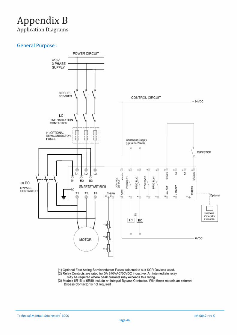
AppendixBApplicationDiagrams
Technical Manual: Smartstart
® 6000 IMI0042 rev K Page 46
General Purpose :
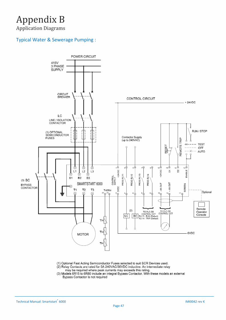
AppendixBApplicationDiagrams
Technical Manual: Smartstart
® 6000 IMI0042 rev K Page 47
Typical Water & Sewerage Pumping :
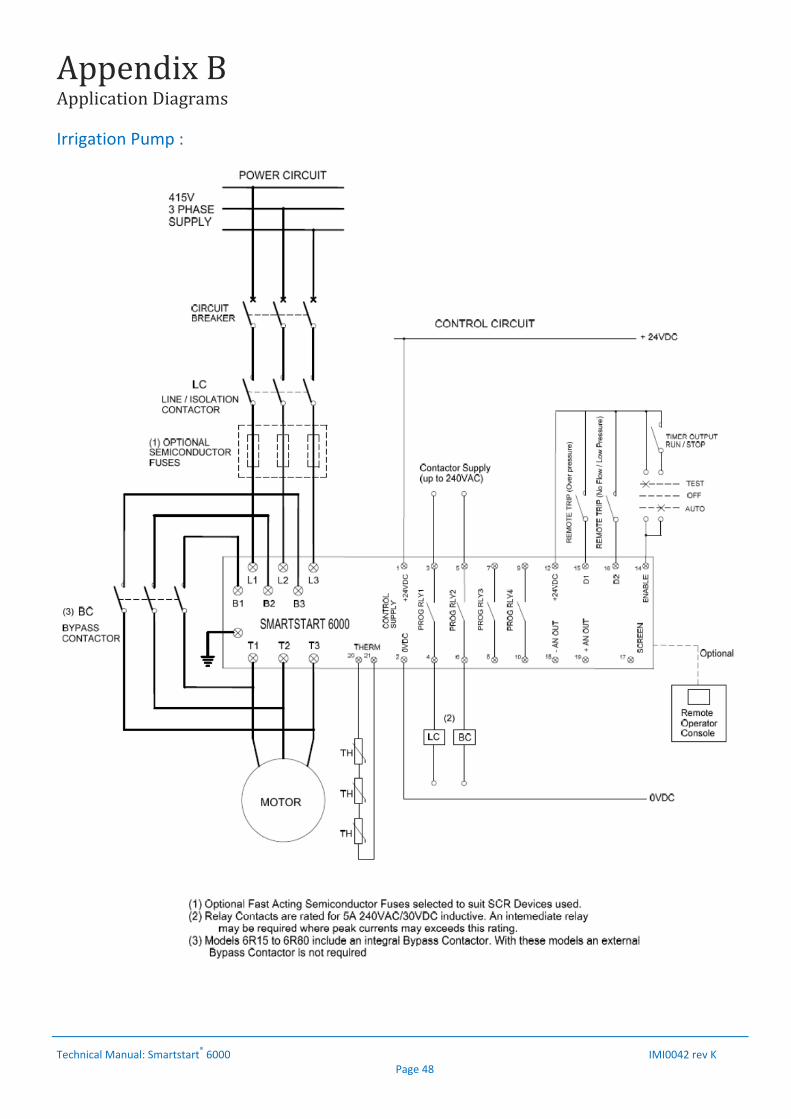
AppendixBApplicationDiagrams
Technical Manual: Smartstart
® 6000 IMI0042 rev K Page 48
Irrigation Pump :
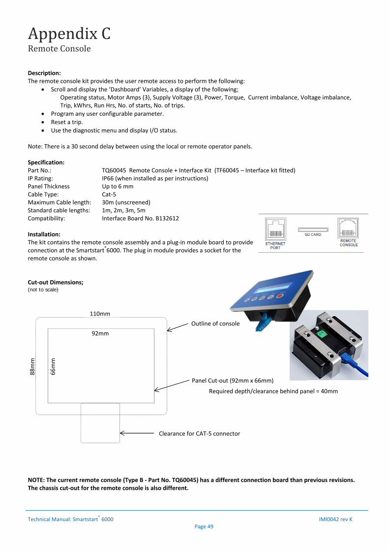
AppendixCRemoteConsole
Technical Manual: Smartstart
® 6000 IMI0042 rev K Page 49
Description: The remote console kit provides the user remote access to perform the following:
Scroll and display the ‘Dashboard’ Variables, a display of the following; Operating status, Motor Amps (3), Supply Voltage (3), Power, Torque, Current imbalance, Voltage imbalance, Trip, kWhrs, Run Hrs, No. of starts, No. of trips.
Program any user configurable parameter.
Reset a trip.
Use the diagnostic menu and display I/O status.
Note: There is a 30 second delay between using the local or remote operator panels. Specification: Part No.: TQ60045 Remote Console + Interface Kit (TF60045 – Interface kit fitted) IP Rating: IP66 (when installed as per instructions) Panel Thickness Up to 6 mm Cable Type: Cat‐5 Maximum Cable length: 30m (unscreened) Standard cable lengths: 1m, 2m, 3m, 5m Compatibility: Interface Board No. B132612 Installation: The kit contains the remote console assembly and a plug‐in module board to provide connection at the Smartstart®6000. The plug in module provides a socket for the remote console as shown. Cut‐out Dimensions; (not to scale) NOTE: The current remote console (Type B ‐ Part No. TQ60045) has a different connection board than previous revisions. The chassis cut‐out for the remote console is also different.
Required depth/clearance behind panel = 40mm
Outline of console
Panel Cut‐out (92mm x 66mm)
92mm
66mm
110mm
88mm
Clearance for CAT‐5 connector
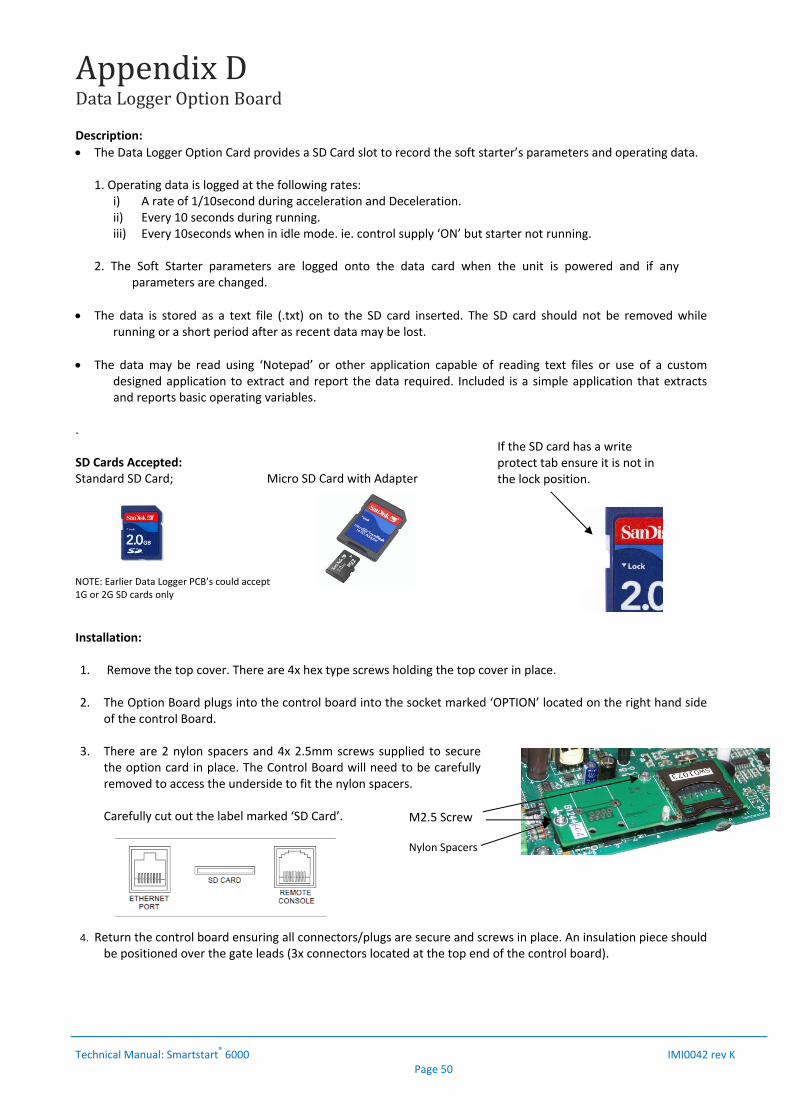
AppendixDDataLoggerOptionBoard
Technical Manual: Smartstart
® 6000 IMI0042 rev K Page 50
Description:
The Data Logger Option Card provides a SD Card slot to record the soft starter’s parameters and operating data.
1. Operating data is logged at the following rates: i) A rate of 1/10second during acceleration and Deceleration. ii) Every 10 seconds during running. iii) Every 10seconds when in idle mode. ie. control supply ‘ON’ but starter not running.
2. The Soft Starter parameters are logged onto the data card when the unit is powered and if any
parameters are changed.
The data is stored as a text file (.txt) on to the SD card inserted. The SD card should not be removed while running or a short period after as recent data may be lost.
The data may be read using ‘Notepad’ or other application capable of reading text files or use of a custom designed application to extract and report the data required. Included is a simple application that extracts and reports basic operating variables.
. SD Cards Accepted: Standard SD Card; Micro SD Card with Adapter
Installation: 1. Remove the top cover. There are 4x hex type screws holding the top cover in place.
2. The Option Board plugs into the control board into the socket marked ‘OPTION’ located on the right hand side
of the control Board.
3. There are 2 nylon spacers and 4x 2.5mm screws supplied to secure the option card in place. The Control Board will need to be carefully removed to access the underside to fit the nylon spacers. Carefully cut out the label marked ‘SD Card’.
4. Return the control board ensuring all connectors/plugs are secure and screws in place. An insulation piece should be positioned over the gate leads (3x connectors located at the top end of the control board).
If the SD card has a write protect tab ensure it is not in the lock position.
NOTE: Earlier Data Logger PCB’s could accept 1G or 2G SD cards only
Nylon Spacers
M2.5 Screw
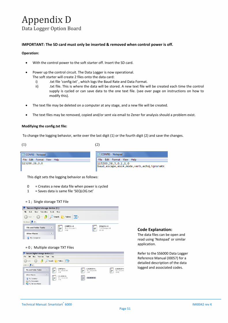
AppendixDDataLoggerOptionBoard
Technical Manual: Smartstart
® 6000 IMI0042 rev K Page 51
IMPORTANT: The SD card must only be inserted & removed when control power is off. Operation:
With the control power to the soft starter off. Insert the SD card.
Power up the control circuit. The Data Logger is now operational. The soft starter will create 2 files onto the data card: i) .txt file ‘config.txt’ , which logs the Baud Rate and Data Format. ii) .txt file. This is where the data will be stored. A new text file will be created each time the control
supply is cycled or can save data to the one text file. (see over page on instructions on how to modify this).
The text file may be deleted on a computer at any stage, and a new file will be created.
The text files may be removed, copied and/or sent via email to Zener for analysis should a problem exist.
Modifying the config.txt file: To change the logging behavior, write over the last digit (1) or the fourth digit (2) and save the changes. (1) (2)
This digit sets the logging behavior as follows: 0 = Creates a new data file when power is cycled 1 = Saves data is same file ‘SEQLOG.txt’
= 1 ; Single storage TXT File
= 0 ; Multiple storage TXT Files
Code Explanation: The data files can be open and read using ‘Notepad’ or similar application. Refer to the SS6000 Data Logger Reference Manual (I0057) for a detailed description of the data logged and associated codes.

AppendixE6WireConnectionusinginternalCT’s
Technical Manual: Smartstart® 6000 IMI0042 rev K Page 52
It may be possible to configure the SMARTSTART 6000 in 6 wire configuration with the CT’s internal. This is subject to the maximum current rating of the bus bar for each size soft starter.
Warning
The current in the ‘LINE L1,L2,L3’ is 1.732x the phase currents of the motor and the soft starter. The input terminals, wiring and bus bar must be rated to operate at these levels continuously. If the continuous current is exceeded the bus bar temperature may rise above acceptable levels. For a 6 Wire configuration using internal CT’s, the motor rated FLC must be within the rating of the soft starter and less than the Maximum bus bar current specified in below.
ChassisA3(6R360)
The 6R360 will operate at its full rating using internal CT’s. Refer to Selection table below or Page 40‐41.
(6R580,6R830)
The 6R580 and 6R830 is limited to a maximum of 830Amps. To achieve the full rating of the soft starter above this current external CT’s are required.
ChassisA2(6R100,6R190,6R220)
The above soft Starters will operate at their full rating using internal CT’s. Refer to Selection table below or Page 40‐41.
Model Light Duty: (Amps)
Standard Duty: (Amps)
Severe Duty: (Amps)
Light Duty: (Amps)
Standard Duty: (Amps)
Severe Duty: (Amps)
Input Bus bar Maximum Continuous
Current Rating
6R10000 173 152 128 180 159 130 180Amps
6R19000 308 270 224 330 290 238 380Amps
6R22000 350 310 255 380 330 269 380Amps
6R36000 590 520 442 635 555 478 830Amps
6R58000 920 815 687 1015 888 731 830Amps
6R83000 1378 1225 1042 1435 1395 1108 830Amps
Continuous Operation Bypass Operation
StarterRating:6WireConfiguration
WiringusinginternalC.T’s
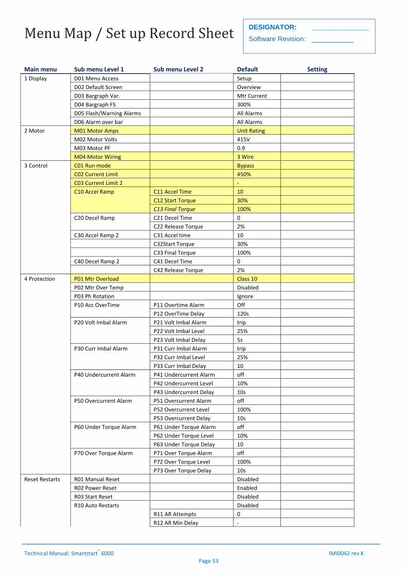
MenuMap/SetupRecordSheet
Technical Manual: Smartstart® 6000 IMI0042 rev K Page 53
DESIGNATOR: _______________
Software Revision: ___________
Main menu Sub menu Level 1 Sub menu Level 2 Default Setting
1 Display D01 Menu Access Setup
D02 Default Screen Overview
D03 Bargraph Var. Mtr Current
D04 Bargraph FS 300%
D05 Flash/Warning Alarms All Alarms
D06 Alarm over bar All Alarms
2 Motor M01 Motor Amps Unit Rating
M02 Motor Volts 415V
M03 Motor PF 0.9
M04 Motor Wiring 3 Wire
3 Control C01 Run mode Bypass
C02 Current Limit 450%
C03 Current Limit 2 ‐
C10 Accel Ramp C11 Accel Time 10
C12 Start Torque 30%
C13 Final Torque 100%
C20 Decel Ramp C21 Decel Time 0
C22 Release Torque 2%
C30 Accel Ramp 2 C31 Accel time 10
C32Start Torque 30%
C33 Final Torque 100%
C40 Decel Ramp 2 C41 Decel Time 0
C42 Release Torque 2%
4 Protection P01 Mtr Overload Class 10
P02 Mtr Over Temp Disabled
P03 Ph Rotation Ignore
P10 Acc OverTime P11 Overtime Alarm Off
P12 OverTime Delay 120s
P20 Volt Imbal Alarm P21 Volt Imbal Alarm trip
P22 Volt Imbal Level 25%
P23 Volt Imbal Delay 5s
P30 Curr Imbal Alarm P31 Curr Imbal Alarm trip
P32 Curr Imbal Level 25%
P33 Curr Imbal Delay 10
P40 Undercurrent Alarm P41 Undercurrent Alarm off
P42 Undercurrent Level 10%
P43 Undercurrent Delay 10s
P50 Overcurrent Alarm P51 Overcurrent Alarm off
P52 Overcurrent Level 100%
P53 Overcurrent Delay 10s
P60 Under Torque Alarm P61 Under Torque Alarm off
P62 Under Torque Level 10%
P63 Under Torque Delay 10
P70 Over Torque Alarm P71 Over Torque Alarm off
P72 Over Torque Level 100%
P73 Over Torque Delay 10s
Reset Restarts R01 Manual Reset Disabled
R02 Power Reset Enabled
R03 Start Reset Disabled
R10 Auto Restarts Disabled
R11 AR Attempts 0
R12 AR Min Delay ‐
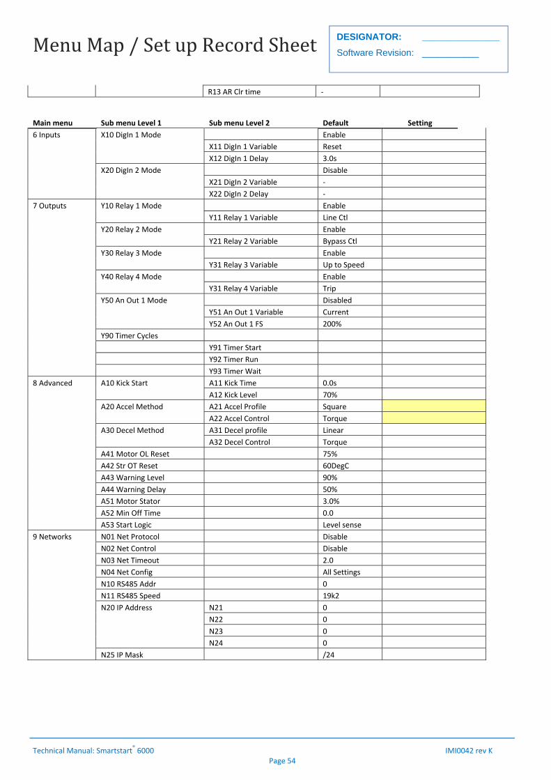
MenuMap/SetupRecordSheet
Technical Manual: Smartstart® 6000 IMI0042 rev K Page 54
DESIGNATOR: _______________
Software Revision: ___________
R13 AR Clr time ‐
Main menu Sub menu Level 1 Sub menu Level 2 Default Setting
6 Inputs X10 DigIn 1 Mode Enable
X11 DigIn 1 Variable Reset
X12 DigIn 1 Delay 3.0s
X20 DigIn 2 Mode Disable
X21 DigIn 2 Variable ‐
X22 DigIn 2 Delay ‐
7 Outputs Y10 Relay 1 Mode Enable
Y11 Relay 1 Variable Line Ctl
Y20 Relay 2 Mode Enable
Y21 Relay 2 Variable Bypass Ctl
Y30 Relay 3 Mode Enable
Y31 Relay 3 Variable Up to Speed
Y40 Relay 4 Mode Enable
Y31 Relay 4 Variable Trip
Y50 An Out 1 Mode Disabled
Y51 An Out 1 Variable Current
Y52 An Out 1 FS 200%
Y90 Timer Cycles
Y91 Timer Start
Y92 Timer Run
Y93 Timer Wait
8 Advanced A10 Kick Start A11 Kick Time 0.0s
A12 Kick Level 70%
A20 Accel Method A21 Accel Profile Square
A22 Accel Control Torque
A30 Decel Method A31 Decel profile Linear
A32 Decel Control Torque
A41 Motor OL Reset 75%
A42 Str OT Reset 60DegC
A43 Warning Level 90%
A44 Warning Delay 50%
A51 Motor Stator 3.0%
A52 Min Off Time 0.0
A53 Start Logic Level sense
9 Networks N01 Net Protocol Disable
N02 Net Control Disable
N03 Net Timeout 2.0
N04 Net Config All Settings
N10 RS485 Addr 0
N11 RS485 Speed 19k2
N20 IP Address N21 0
N22 0
N23 0
N24 0
N25 IP Mask /24