soen 6011 software engineering processes section ss fall 2007 dr greg butler...
TRANSCRIPT

SOEN 6011Software Engineering Processes
Section SS Fall 2007
Dr Greg Butlerhttp://www.cs.concordia.ca/~gregb/home/soen6011-f2007.html

Week 11• Software Architecture
• 4+1 Views
• Siemen’s Approach

Software Architecture: Definitions
• … for a system is the structure … which consist of elements, their externally visible properties, and the relationships among them.
• The fundamental organization of a system [as] embodied in its components, their relationships to each other, and to the environment, and the principles guiding its design and evolution. (IEEE 1471-2000).

Architecture: Benefits?
• Contributes to elicitation of requirements.• First design: can already assess / determine
– satisfaction of requirements.– Work allocation / distribution (schedule).
• Instructional: useful to learn about system.– Initial development & maintenance.
• Reuse of the architectural style / framework.• Also …

Conceptual Integrity …
• … is central to achieving product quality.• Also called Architectural Integrity.• Coherent conceptual (design) model
makes product easier to understand, hence easier to …– Develop (e.g. Design, test),– Learn to use: customer, I&C, sales & marketing– Maintain.
• How to achieve conceptual integrity? …

System Architect
• Custodian of product ensures– Design coherence.– Also, to some extent, Interface coherence (esp.
UI).

System Architect
• Full-time job!– Separation of architecture from
implementation.
• Project size hierarchy of architects.
• “Single mind”
• Having a system architect is an effective means of achieving conceptual integrity.

Components
• S/W entities …– Systems (e.g. COTS), subsystems, frameworks,
packages, layers, libraries, modules, classes, objects, executables, DLLs, plug-ins, …
– Processes, tasks.
• Physical– Network elements.– Processing elements.– Databases.

Interrelationships
• Static:– Interface dependencies: e.g. uses/import.– Containment, inheritance, subtype, …– Data dependencies (database applications).– …
• Dynamic:– Thread of control.– Dataflow.– …

Documentation: Putting it all together
• How best to capture all of these different kinds of components and their interrelationships?
• Consider …
View Based Documentation of Architectures
• Architecture Document =View A +
View B +
View C + …
View X +
“Beyond Views”

“4+1” View Model of Architecture
• By Philippe Kruchten [Kruchten95](URL to paper given on web site.)
• Rational Unified Process.
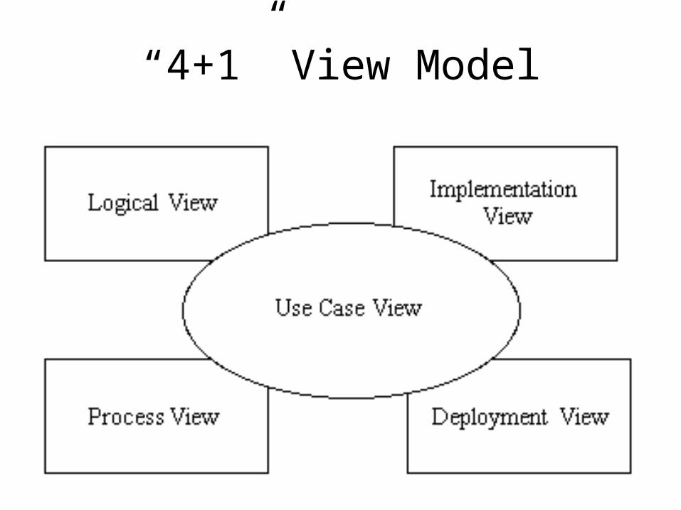
“4+1” View Model
Deployment/
Implementation/

References
• Kruchten95, becoming a bit dated.• RUP documentation
– Available in lab.– Also includes samples.
• To access RUP from lab machines– Launch the Rational Unified Process.
• From the Overview page …• Select Analysis and Design• At the top of this page select “Artifacts”• Select “Software Architecture Documents”• You will see links to the examples … . Note that I do not
consider the examples complete.

“4+1” VM (Alternate names)

“5+1” View Model
• = 4 + 1 + data view.
• Other combinations of views are possible.

“4+1”: Let us look at each view
Deployment/
Implementation/

• Main goal: present architecturally significant use cases either:– Duplicated from req. doc. – Named and reference given to req. doc.
• These use cases are to help highlight main– Architectural decisions / choices
Use Case View

Logical View: Main Goals
• Convey …– Overall structure and – Interfaces to the environment, in a manner
that is– conceptually as simple as possible
• Challenge: find right level of detail.

Logical View & Requirements
• Main focus: functional.
• It should be possible to assess (up to a certain level of detail) whether requirements will be satisfied by the proposed architectural design.

Logical View: Components & …
• Components:– active classes, classes, – modules, – packages, – subsystems, …
• Connectors (interrelationships):– Usage.– Containment, aggregation.– Inheritance, instantiation.
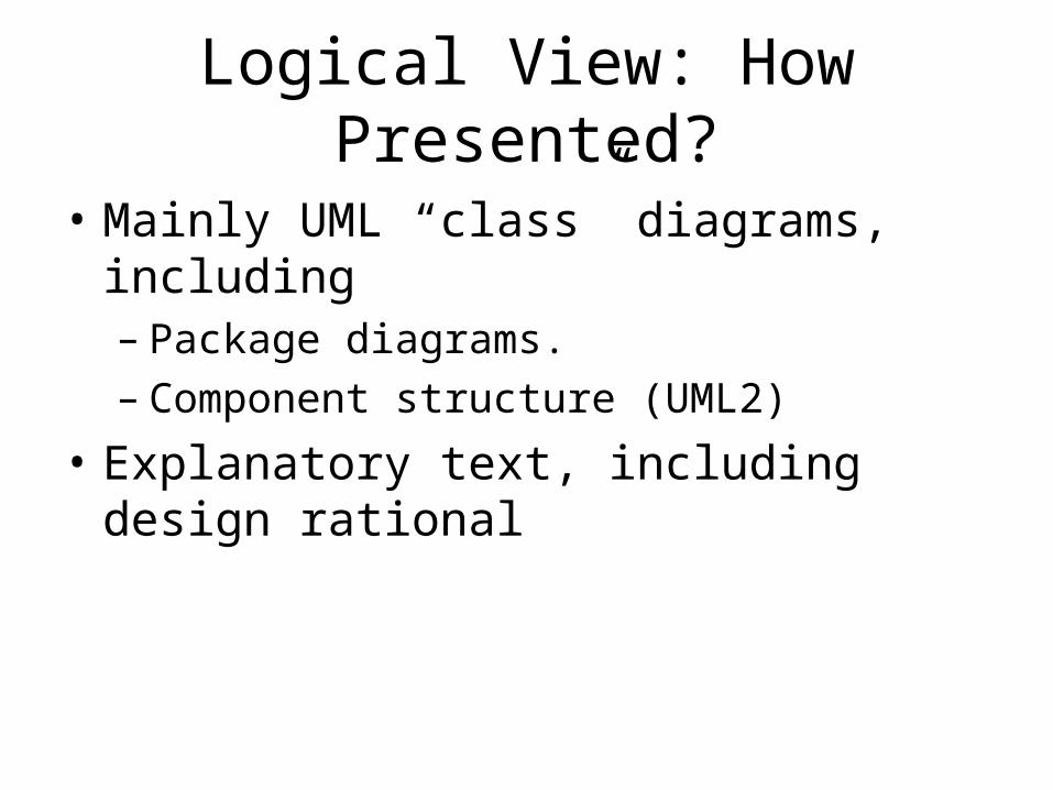
Logical View: How Presented?
• Mainly UML “class” diagrams, including– Package diagrams.– Component structure (UML2)
• Explanatory text, including design rational

Logical View, Example
• You have seen many examples of class and package diagrams.
• UML 2 component diagrams you have seen as well …

Logical View (e.g. Kruchten)

Process View
• Components: processes, tasks, …– group of tasks : single exec. unit.– Control: start, shutdown, recover, restore– Primary / secondary (redundancy)
• Interrelationships:– Communication
• Allocation of – Logical view components to processes/tasks.
• Synchronization mechanisms

Process View – e.g. (Kruchten)

Process View – ex.Logical View
Components

Implementation (Development)View
• Actual S/W organization.• Components:
– Libraries, subsystems, exec., object files, …– Most common top-level arch. style: layers
• Connectors: containment, dependencies, …• Allocate logical components to impl. comp.• Reuse:
– Off-the-shelf.– “To-the-shelf”: sharing with other projects.

Implementation View – illustration

Deployment (Physical) View
• Components: processors, processing nodes, …• Network topology.
– Usually several topo’s are supported.– S/W should be relatively independent of topo.
• Allocation of process view elements to H/W (processing nodes).
• Examples:– Network elt: Process mapping into application cards.– Network Mgmt: one or more NOCs.

Deployment View - illustration

Deployment View - illustration
Siemens Four View Model
• Reference:Applied Software Architecture by C. Hofmeister, R. Nord and D. Soni.

Conceptual View
Module View
Code View
Execu-tion
View
Source Code
H/WArch.
Siemens Four View Model: Overview
S/W Architecture

Comparing the View Models
4+1• Logical• Implementation
(Development)
• Process• Deployment (Physical)
• (Use Case)
S4VM• Conceptual• Module• Execution• Code

S4VM OverviewS4VM: in more detail. Notice activity
groups in each view are the same …

S4VM Activities Groups in each view
• For each view perform– Global analysis
(Mostly the same for each view.)
– Central design tasks.(Specific to each view.)
– Final design tasks.(Specific to each view.)

Overview
Global Analysis: Purpose
• To identify issues (early) so that strategies can be proposed to resolve them.
• (Architectural) Factors can be seen merely as a means of organizing (group) issues.

Global Analysis
Activities:
1. Analyze Factors.
2. Identify Issues.
3. Develop Strategies.
1. Analyze Factors - purpose
• Identify and describe factors that can influence the system architecture.
• Document the factors.

1. Analyze Factors
• Use given factor categorization / list to kickoff.
• For each factor consider:– How it relates to the project.– Flexibility and changeability.– Impact.

Factor Categorization (e.g. SFVM)
• Organizational
• Technological
• Product

Organizational Factors
Top-level grouping of factors:
• O1: Management
• O2: Staff skills, interests, strengths, weaknesses.
• O3: Process and development environment.
• O4: Development schedule.
• O5: Development budget.

O1: Management, further refined …
• Build vs. buy.
• Schedule vs. functionality.
• Environment.
• Business goals.

Ex. Project Factor Analysis Output
O1: Management• O1.1: Build vs. buy
There is a mild preference to build.– Flexibility & changeability: organization will consider
buy if justified.– Impact: moderate impact on meeting schedule.
• O1.2: Schedule vs. functionalityPreference for meeting schedule over some features…– Flex.&chng: negotiable for some features …– …
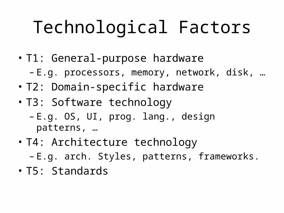
Technological Factors
• T1: General-purpose hardware– E.g. processors, memory, network, disk, …
• T2: Domain-specific hardware
• T3: Software technology– E.g. OS, UI, prog. lang., design patterns, …
• T4: Architecture technology– E.g. arch. Styles, patterns, frameworks.
• T5: Standards

Product Factors
• P1: Functional features
• P2: User interface
• P3: Performance
• P4: Dependability
• P5: Failure detection, reporting, recover
• P6: Service
• P7: Product Cost

What is an Issue?
• A (potential) problem.
2. Identify Issues
• Key issues influencing architectural design which are to be resolved.
• Consider influencing factors.
Issue: Skill Deficiencies
• Influencing factors:
O2: Staff skills– O2.3 (Experience with multithreading): only
one developer has multithreading experience.– O2.4 (Experience with multiprocessor
systems): only two developers …

3. Develop Strategies
What is a strategy?

What is a Strategy?
• A means by which one or more issues are to be resolved, partially or totally.

3. Develop Strategies
• For each issue:– Develop strategies to address issue.– Identify related strategies.
Ex. Issue: Changes in Hardware
• Changes in both general-purpose and domain-specific hardware are anticipated on a regular basis. The challenge is to reduce the effort and time involved in adapting the product to the new hardware.
• Influencing factors: T1 (General-purpose H/W), T2 (Domain-specific H/W).
• Solutions: … ?

Ex. Strategies
• Encapsulate hardware

S4VM: Conceptual View
Conceptual View – Documentation
• Structure– Configurations of:
components, connectors, ports, roles, protocols.
• Behavior– State diagrams.– Sequence diagrams.– Natural language.

Conceptual View – Activities
• Global analysis.
• Central design tasks.
• Final design task.

Conceptual V.: Central Design Tasks
• Create conceptual– Components, – Connectors (and ports, roles, protocols)– Configuration.
• Global evaluation

Conceptual V.: Final Design Tasks
• Resource budgeting– Resources used by the software, but – Resources themselves can be H/W or S/W.
• Examples of resources include:– Memory, – CPU time,– Bandwidth,– … .

Global Evaluation
• Evaluate design decisions– Continually, relative to results of global
analysis.– Periodically, w.r.t. interactions among
themselves.
• During central design tasks.

Module View – Activities
• What is the top level grouping of activities?

Module View – Activities
• Global analysis.
• Central design tasks.
• Final design task.
Module View, Central Design Tasks
• Definition of– Subsystems.– Layers– Modules
• Allocation of conceptual elements to the above.
• Global evaluation.

Module View, Final Design Tasks
• Design of (key) module interfaces– Operations:
• name, signature (return type, parameter type).
– Behavior (via specification).

What is a “Module”?
• You can think of this as a UML package.
• Does not imply that code will be non OO.
• In execution view, will eventually “hold” either OO (classes,…) or non OO code.