society of mlnlng engineers a · society of mlnlng engineers a i ... sf total gangue rejection...
TRANSCRIPT

,> . : PREPRINT NO.
SOCIETY OF MlNlNG ENGINEERS A I of AIME I
345 EAST 47TH STREET, NEW YORK 17, N.V.
1 DETERMINATION OF THE WGNETIC SEPARATION
Norman F . Schulz + - 1
Research Asaoclate . ? . , $ ,
Mines Experimenk Station University of Minpeqota Minneapolisp Minnesota
: P~emnted at the Rocky Mountain Minerals, Conference- # S@-eSstty of MSnlng Engineers of AIME, Fall Meeting,
Sq1t &ake City, Utah, September 11 t o 13, 1963.
Permission is hereby given to publish with appropriate ocknowledgments, excerpts or summories not to exceed one-fourth of the entire text of the paper. Permission to print in more extended form subsequent to publication by the Institute must be obtained from the Secretary of the Society of Mining Engineers of A.I.M.E.
I f and when this paper is published by the Institute, it may embody certain changes mode by agreement between the Technical Publications Committee and the author, so that the form in which it appears here i s not necessarily that in which it may be
1 publish J later.


DETERMINATION OF THE MAGNETIC SEPARATION 6 3 ~ 3 0 2 CHARACTERISTIC WITH THE DAVIS MAGNETIC TUBE
Norman F. Schulz, Research Associate Mines Experiment Station, University of lMinne sota
Minneapolis, Minnesota
Introduction
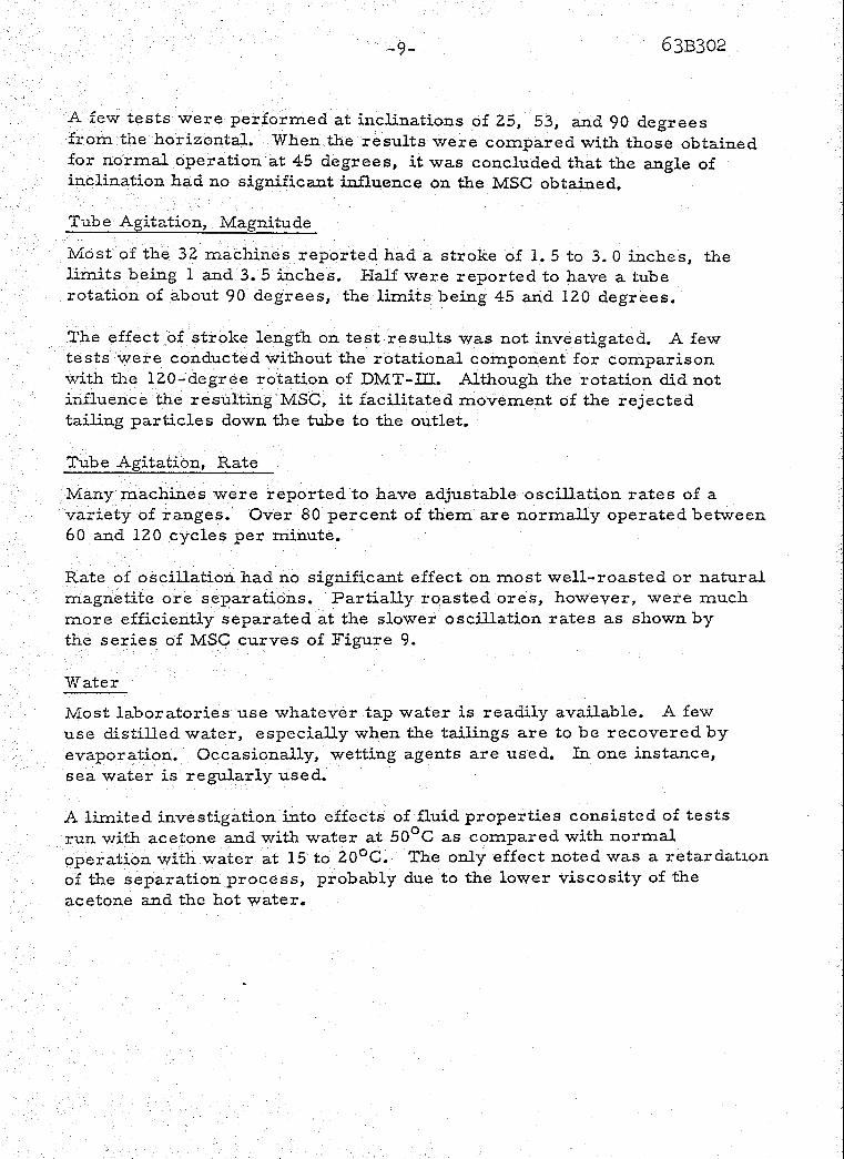
The Davis magnetic tube concentrator i s a laboratory machine designed to separate a small sample of pulverized magnetic iron ore into magnetic and non-magnetic fractions. It was developed in 1921 by mechanization of a test previously performed manually. (1)(2)(3)(4) No significant changes have been made in the design of the apparatus since that time. The Davis magnetic tube test continues to serve as a practical basis for judging the amenability of an ore to magnetic separation and for controlling magnetic separation plant operations . The apparatus consists of an inclined cylindrical glass tube supported adj acept to closely spaced pointed poles of a powerful C-magnet. (Figure 1). To conduct a tube test, a sample of a suitably prepared ore i s poured into the water-filled tube. With wash water flowing through, the tube is oscillated to gradually reject the weakly magnetic ore particles until the desired degree of separation i s attained. Both the magnetic concentrate and the tailings may be recovered for examination.
With natural magnetite ores, usual practice has been to perform a single tube test on a specifically prepared ore sample, continuing the separation until judged "complete" according to the operator's experience. The resulting concentrate grade and iron recovery were used as a basis for controlling plant operations. However, when applied to certain roasted i ron ores, this method yields tes t results which a re often more dependent on the experience and judgment of the operator than on the ore itself.
The purpose of this investigation was to evaluate the effects of variables in equipment and procedure on tube test results. This information was then to be used to formulate specifications, preferably within the practical ranges of existing machines, for test procedures capable of yielding precise and meaningful data concerning the magnetic separation of any magnetite ore, regardless of i ts origin.

A survey of current practice was conducted among laboratories using the Davis tube test, Thousands of tube tests were performed to experimenta evaliia'ie the variables most likely to affect test results. A simple method was then sought for adequately interpreting tube test results.
I Surnmarv of Recommended Test Procedure
Davis Magnetic Tube Tester:
Pole pieces: Conical, 90 degree included angle, on common horizontal axis.
Pole gap: 3/8 to 314 inch. Magnetic Field: 4000 gauss or more midway between poles. Tube: Cylindrical, glass, 1 inch I. D., 1 118 inch 0. D.
(570 tolerance). Tube position: Axis 40 to 50 degrees from hori-zontal,
less than 1 / 16 inch clearance from pole pieces. Tube agitation: Stroke 1 to 3 inches, rotation 60 to 120 degrees.
Test Procedure:
Ore sample: 10 g. Operation: Agitation, 60 to 150 cycles per minute
Water, 50 to 500 cc per minute Time, 3 to 20 minutes Number of tests, three o r more, at conditions
selected to yield data in region of sharpest *curvature of MSC or other region of interest.
Product recovery and examination: Stop machine, drain water from tube to magnet level, remove tube from machine, and rinse contents into a glass beaker. Decant the water from the concentrate with the aid of a hand magnet held at the bottom of the beaker. Dry, weigh, and as say the concentrate.
Data processing: Calculate iron recoveries from sample and concentrate weights and assays. Plot concentrate grade against iron recovery and connect points by a smooth curve.

Conclusions
l it; ~s not ieasible to attempt to define a single Davis magnetic tube test
I I
which could be applied to alf magnetic ores.
The Magnetic Separation Characteristic interprets the results of tube
I tests in a significant manner. It expresses the actual course of separation rather than merely the achievement of a single arbitrary tube test based on the fallacious assumption of an absolute end-point to the separation. Its general concept i s applicable to any separation process.
The magnetic field intensity midway between the magnet poles of a Davis magnetic tube concentrator should be a t least 4000 gauss. Machines with lower field intensity can be used for routine test work i f suitably c alib rate d.
Variations i n test details a re more likely to influence test results for artificial magnetite ores, and especially partially roasted iron ores, than for natural magnetite ores such as taconite.
Magnetic Separation by the Da*s Tube
Mechanical separation of a specified mineral component from an ore ilsually requires comminution to fine sizes for sufficient liberation. Some distinguishing property of the mineral i s then exploited to sor t the desired mineral particles from the gangue particles.
The magnetic separation of iron ores i s based on the fact that magnetite, Fe304, i s strongly attracted by a magnetic field while the gangue mineral- a re not. Maghemite, ~ - F e ~ 0 ~ , which may occur in certain chemically processed ores, responds similarly to magnetite. The magnetic process Is practical only when the loss of iron in the form of relatively non-magnetic hematite, Fe203, goethite, Fe203. nH20, or other iron mineral can be tolerated.
i+n the Davis magnetic tube concentrator, magnetic attraction holds magnetically susceptible particles in a magnetic field. Forces due to gravity, inertia, and fluid- solid friction tend to remove the l e s s susceptible ?articles from the field. The probability that a given middling particle

- 4 - I
6 3 ~ 3 0 2
wil l bc rrrjcctcd from ";rm tube 3R a given pcriad of 'time is an inverse li~nction sf i t s snagnctjte content, with Borne mcrWicatiora. duc to p a r ~ c l e ~ i z o and mineral specific gradties. The net result; i s that a r c parlLiclcs tend to be rojectad in their order of increasing magnc t i t~ coatcat, \vhils 3
t$lc retained p o r ~ o n or magnetic concentrate iracrcae5lcs in grade contin- uously during the process,
I 1 ! i I
The $MagneEc S c p z r a t i ~ n Gharacteristic" or "MSCrf of a magnetite ore i s I
the correlation bchvcea eoncentrate grade and iron recovery which occurL d u r k g a magnctic scparatian process, I t i s a function of the structure, ~,szr,position, and degree of liberation of the ore and of the particular process employed,
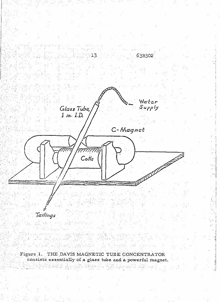
The relationships which migigkf; occur between grade and iron recovery during magnetic separation are iuustrated in Figure 2, The ideal course sf magnefic separation of a perfectly liberated magnetite ore would esnsist sf total gangue rejection without loss of magneti%e, leaving a pure magnetite concentrate of 72.4 percent iron, The ideal course for an a re sample coPltaining middling particles .ivould consist of rejection of particles in their order of increasing magnetite proportion, a s represented by curve I of Figure 2, An experimental separation, being less than 180 percent efficient, might foUsw the course re?resented by curve E s f Y i ~ x r e 2.
Tlsc IMSC obtained with the Davis 'tube represents a highly efficient course s f magnetic separakion for a specifically prepared o re sample. The overall separation efficiency achieved in a well-designed plant in which ,mineral liberation is an integral part of the operation should be at least a s good as that of the Davis tube,

Beqause of the nature of magnetic separation, it i s neither practical nor necessary to determine more +an the relatively small portion of the MSG curves included within the shaded rectangle of Figure 3.
Data for MSC curves were obtained by processing identical portions of a prepared ore sample to different stages of separation in a Davis t ~ b e . Much of the experimental work was concerned with establishing test specifications which would yield an MSC a s close to ideality a s practicable and with minimum modification of current apparatus or techniques.
Equipment
A1"Lough three Davis magnetic tube machines were available (see Table I), this investigation was conducted on DMT-IU: with only enough work with DMT-I and DMT-LI to establish correlations among the three. Magnetic fields were supplied by direct current electromagnets having three-inch diameter cores capped by 90-degree conical pole pieces. The magnetic field intensity of DMT-fPI. was controlled by a rheostat in the field circuit.
Agitation was provided by variable speea motors through a crank and slide mechanism which oscillated the tube both longitudinally and r otationally.
A straight cylindrical glass tube, 1. 0 inch I. D, and 1. 12 inch 0. D. , with the lower, outlet end tapered to 0.25 inch I. D. was normally used, Tubes of 0. 75 and 1. 25 inch I. D. were available for special tests. The conven- tional side a r m for water inlet and enlargement a t the upper end were eliminated. A drawn glass tip of about 0.05 inch I. D. was inserted in the rubber tubing on the lower end during operation at low water rates to prevent air bubble intake. The water supply was regulated by a needle valve and flowmeter.
An analytical balance was used to weigh samples to the nearest milligram in a brass scoop designed to transfer the ore sample to the tube. Concen- trates were collected in 250 m l glass beake.rs and a small hand magnet was -
used to aid the decanting operation.

TABLE I DAVIS MAGNETIC TUBE MACHINES
DMT-I Hand-made
Machine fixed poles
Pole gap, inches 0.58 Magnetic Field*
Sustained, 1 10 v 2900 At 1.0 amp. -
Agitation Frequencies,
cycles per min. 82-97 Stroke length, in. 2.0 Xotation, degrees 90
DMT-II Hand-made
adjustable poles
0- 1.5
DIM T- ITf Dings Type EDTT
fixed poles
):: Magnetic field measured at pole centerline midway between points, with Bell, Inc. , Model 110 Gaussmeter.

-7-
Ore Samples
The tube test investigations were conducted on magnetite ores only, including a variety of roasted iron ores and a few magnetic taconite All were pulverized to approximately normal size distributions wiLh top particle sizes of 44 to 149 microns ( 3 2 5 to 100 mesh) in single stage operations with either a pebble mill or a Davis sample grinder.
'i'he structure and composition of magnetic ores and the techniques employeu to liberate the mineral components a re not so much basic factors affecting the accuracy of tube test results a s they a r e properties to be studied by means of the tube test. Therefore, the physical properties of an ore sample were considered to be outside influences affecting only the allowable ranges of independent tes t variables.
Results
Questionnaires concerning details of equipment and procedure for the Davis magnetic tube test were sent to twenty-three laboratories outside the mines Experiment Station. The contents of the nineteen replies and Station experience a re summarized together with the results of this inve stigation under the following headings.
Magnet Poles
No machines were reported to have other than coaxial 90-degree right circular conical magnet poles. The pole gaps varied only slightly f rom 0.44 to 0. 75 inches, 80 percent being 0. 50 to 0,63 inches.
Experimental results with DMT-II showed only minor effects on the MSC due to variation in pole gap from 0 to 1 , 3 inches and no significant effects over the total reported range.
Magnetic Field
The effective magnetic field strength in a Davis tube, which i s approximately xoportional to the central field intensity (midway between the magnet poles), .nust be sufficient to ~ninimize loss of desirable ore. Test results at ~ a r i o u s field intensities yielded the MSG curves of Figure 5.

Of the 26 machines reported in the survey, 9 had central field intensities of less than 3500 gauss and only 13 had fields of 4000 gauss or more, Test results obtained on different machines can be expected to agree only if the fields a re very similar or above 4000 gauss.
Tube Clearance
Tube wall thickness plus clearance between tube and magnet poles consti- tute the distance separating the pulp colurnn from the poles. In existing machines, this total distance ranged from 0.05 to 8.32 inch, 80 pe2ceiz.i; being less than 0-20 inch.
Experimentally, increased clearance between tube and poles tended to lower the resulting MSC curve slightly a s shown in Figure 6 ,
Tube Diameter
About 75 percent of the tubes currently in use a r e 0.94 to 1,06 inch I, D, The largest reported was 1. 38 inch and the smallest 0.88 inch,
Variations in tube diameter from 0. 75 to 1.25 inch did not affect the separation efficiency of well-roasted or natural magnetite ores. The maximum sample quantity which could be separated efficiently, however, was approximately proportional to the cross sectional a rea of the tube. The relationship between i ron recovery and sample quantity for the three tube sizes i s shown in Figure 7 for a well-roasted ore.
Similar data for a partially roasted ore, Figure 8, shows that both the limiting sample quantity and separation efficiency a re affected by tube &it-meter, The rather peculiar behavior sf partially roas%ed ores tows-~-d magnetic separation remains as a subject for future study,
Tube hclination
Davis tube tests a r e regularly performed with the tube inclined at 40 to 50 degrees by 80 percent of the operators reporting, while the remaining 20 percent prefer to operate at l e s s than 40 degrees from the horizontal. One reported using an angle of 5 degrees during early stages of a test and finishing a t 45 degrees. All the machines could be operated C ~ P B ~ E X I -
ientHy at 45 degrees.
A few tests were performed a t inclinations of 25, 53, and 90 degrees from the horizontal. When the results were compared with those obtained for normal operation at 45 degrees, i t was concluded that the angle of inclination had no significant influence on the MSG obtained.
Tab e Agitation, Magnitude
iMost of the 32 machines reported had a stroke of 1.5 to 3.0 inches, the limits being 1 and 3.5 inches. Half were reported to have a tube rotation of about 90 degrees, the limits being 45 and 120 degrees.
The effect of stroke length on test results was not investigated. A few tests were conducted without the rotational component for comparison with "he 120-degree rotation of DMT-UI. Although the rotation did not influence the resulting MSG, it facilitated movement of the rejected tailing particles down the tube to the outlet.
Tube Agitation, Rate
Many machines were reported to have adjustable oscillation rates of a variety of ranges. Over 80 percent of them a re normally operated between 60 and 120 cycles per minute.
Rate of oscillation had no significant effect on most well-roasted or natural magnetite ore separations. Partially roasted ores, however, were much more efficiently separated at the slower oscillation rates a s shown by the ser ies of MSG curves of Figure 9.
Water
most laboratories use whatever tap water is readily available. A few use distilled water, especially when the tailings a r e to be recovered by evaporation, Occasionally, wetting agents a re used. En one instance, sea water i s regularly used.
A limited investigation into effects of fluid properties consisted of tes ts run with acetone and with water at 5 0 O ~ a s compared with normal operation with water at 15' to 20°C. The only effect noted was a re tarda t~on of the separation process, probably due to the lower viscosity of the acetone and the hot vater .

-10- 6 3 ~ 3 0 2
The addition of a wetting agent to the water supply, 0.1 cc Aersol MA 80 percent per liter, produced no discernible effect on tube test results,
Water Rate
The water flow rate used in tube tests varied widely among operators. About 25 percent specified rates between 100 and 200 cc per minute, 50 percent between 200 and 1000 cc per minute, and the res t higher rates. The highest reported rate was 2300 c-c per minute for a machine having a 1, 13 inch I. D, tube.
In tests run here on roasted ores, water rates from 10 to 1000 cc per minute hadno significant effect on results. The frictional forces acti on magnetic particles held in the tube due to a water rate of 1000 cc p minute are similar to those due to 2-inch oscillations at 25 cycles per minute,
Time
Although some laboratories reported running tube tests until the outlet water i s "clear, " others specified times of 3 to 20 minutes. The total amount of water used varied from 0.5 to 34 li ters per test,
In this investigation, time was found to be a purely extensive variable, having no effect on the iWSC of an ore, but being useful in obtaining the necessary spread of data to plot the desired MSG curves,
The degree of separation achieved in the Davis tube for a typical roasted ore was dependent on the total amount of water passed regardless of water rate between SO and 500 cc per minute.
Sample Quantity
Since there must obviously be a maximum sample quantity which the Davis tube c in handle effectively, a program was undertaken to correlate test results with the amount of ore sample treated.
Current practice among laboratories using the test cdUs for samples of 3 to 20 grams, most commonly 10 to 15 g r m s , andup to 50 grams on very lean ores,

Experimental results showed that tests on well-roasted or natural magnetite ores of 20 to 40 percent total iron content could be run effectively on any quantity up to about 20 grams without seriously affecting the MSG obtained. (See Figure 7). Some ores yielded consistent results on samples as large as 50 grams.
Some partially roasted ores were most efficiently separated at a sample weight of 15 grams. The i ron recovery at a given concentrate grade was lower for both larger and smaller samples. _(See Figure 8).
An optimum sample amount applicable to nearly all ores appeared to be about 10 grams for a 1 inch I. D. tube.
Acknowledgements
This investigation was part of a continuing project on magnetic roasting and separation of lean iron ores being conducted as a normal function of the Mines Experiment Station of the University of Minnesota. The author wishes to thank the companies and individuals who furnished requested jcnformation about Davis tube equipment and procedures in current use.

References
1. E. W. Davis, "Magnetic Concentrator , " U. S. Pat. 1, 474, 624,. (1921).
2. E. W. Davis, "Magnetic Concentration of I ron Ore, pp. 56-59, Bull. No. 9, Mines Exper iment Station, Universi ty of Minnesota, (1921).
3 . E. W. Davis, "Magnetic Roasting of Iron Ore, "
pp. 13- 16, Bull. No. 13, Mines Exper iment Station, Universi ty of Minnesota, (1937).
4. R. S. Dean and C. w .' Davis, "Magnetic Separat ion of Ores , Bull. No. 425, U. S. Bureau of Mines, (1941).
20 40 60 80 100 IRON RECOVERY, C&
I
i i Figure 2 . THE MAGNETIC SEPARATION CHARACTERISTIC
QiMSC) represents the course of magnetic separation of a pulverized ore sample. If the magnetite in an ore i s 10070 liberated, the ideal course would be the vertical line from Go, iron content of the head sample, to Cc = C,, iron content of pure &magnetite. An experimental separation of such a
i , material might follow curve P. If the ideal separation of an
incompletely liberated ore is represented by curve I, an actual separation would yield an MSC such as indicated by curve E.

15 . 6 3 ~ 3 0 2
1 I 0 20 40 60 €32 SO0 IRON RECOVERY, a/,
Figure 3 . TYPICAL MSC CURVES for taconite, T, and roasted ore, R, illustrate the contrast between them: (C, is the limiting grade for magnetite, 72.4% Fe).
Taconite, T: 34,270 Fe, ( ~ e t + / ~ e ) = 0.41 Roasted Ore, R: 40.07' Fe, ( F e t t / F e ) = 0.21


$ IRON REGOVERY# %
Figure 6. INCREASED TUBE CLEARANCE SHIFTS MSG to lower value. For best operation, the total.distance between pulp column and magnet pole faces should be a minimum. Distance, dl equals clearance plus tube wall thickness. Ore: 35. 5% Fe, ( F e + + / ~ e ) = 0.26.
- - - --- - -- -


Figure 9. THE MSG DEPENDS ON OSCILLATION RATE in the case of a partially converted iron ore, 3 6 . 2 % Fe, (Fe++/Fe) = 0. 09. The lowest rate was attained by intermittent operation at the minimum drive speed of 4A cycles per minute.