sobré 3d profile - rc airplanes, multirotors, cars ... · (5th servo with optional variable pitch...
TRANSCRIPT

SpecificationsWingspan: 33.25in(845mm)Length: 34.5in(875mm)WingArea: 260sqin(16.8sqdm)Weightw/oBattery: 6.25–7.5oz(175–215g)Weightw/Battery: 7.5–9.25oz(215–260g)
Sobré 3D ProfileAssembly Manual
Designed by: George Hicks
& Jon Leyland
� E-flite Sobré 3D Profile Assembly Manual
Introduction
TheSobré3DProfilewasdesignedbyGeorgeHicksandJonLeyland,theSobré3DARFhassuperbslowflightresponsivenesssoyoucanflyhigh-alpha3Dwithauthority.
ItscarbonfiberreinforcedDepronfoamconstructionthatprovidesthesolid,precisefeelofabalsaprofileplanewithouttheweight.ThisallowsyoutoflytheSobré3Deitherinsideoroutside.
TheSobréisconstructedfrom3mmlaser-cutDepronfoam—thestandardfordurabilityandqualityforpro3Dfoamiepilotseverywhere.Allpiecescomewithavibrantscreenprintedtrimscheme.Carbon Rod Reinforcement
MuchoftheexceptionalflightperformanceoftheSobrécomesfromitscarbon-reinforcedairframethateliminatesflexsocontrolresponseiscrispandprecise.Theleadingandtrailingedgesofthewingcomeoutoftheboxwithfactory-appliedcarbonstrips.Carbonrodsarealsoincludedthatfurtherstrengthenthefuselageandtail.
Using the Manual
Thismanualisdividedintosectionstohelpmakeassemblyeasiertounderstand,andtoprovidebreaksbetweeneachmajorsection.Inaddition,checkboxeshavebeenplacednexttoeachsteptokeeptrackofeachstepcompleted.Stepswithasinglecircle()areperformedonce,whilestepswithtwocircles()indicatethatthestepwillrequirerepeating,suchasforarightorleftwingpanel,twoservos,etc.
Remembertotakeyourtimeandfollowthedirections.
Table of ContentsSpecifications........................................................................ 1Introduction........................................................................... 2UsingtheManual.................................................................. 2ContentsofKit/PartsLayout................................................... 3RequiredRadioEquipment..................................................... 3OutrunnerSetup.................................................................... 4VariablePitchPropOutrunnerSetup...................................... 4OptionalAccessories............................................................. 4NoteonLithiumPolymerBatteries........................................... 4RequiredToolsandAdhesives................................................ 4Warning............................................................................... 5WarrantyPeriod.................................................................... 5LimitedWarranty................................................................... 5DamageLimits...................................................................... 6SafetyPrecautions................................................................. 6Questions,Assistance,andRepairs........................................ 6InspectionorRepairs............................................................. 6WarrantyInspectionandRepairs........................................... 6Non-WarrantyRepairs.......................................................... 7Safety,Precautions,andWarnings......................................... 7AirframeAssembly................................................................ 8InstallingtheBracing........................................................... 12RadioInstallation................................................................. 14MotorandBatteryInstallation.............................................. 18OptionalVariablePitchPropInstallation............................... 23LandingGearInstallation..................................................... 24InstallingtheSideForceGenerators...................................... 26ControlThrows.................................................................... 28CenterofGravity................................................................. 28RangeTestingtheRadio....................................................... 29Preflight.............................................................................. 29FlyingtheSobré.................................................................. 302007OfficialAMANationalModelAircraftSafetyCode...... 31
3E-flite Sobré 3D Profile Assembly Manual
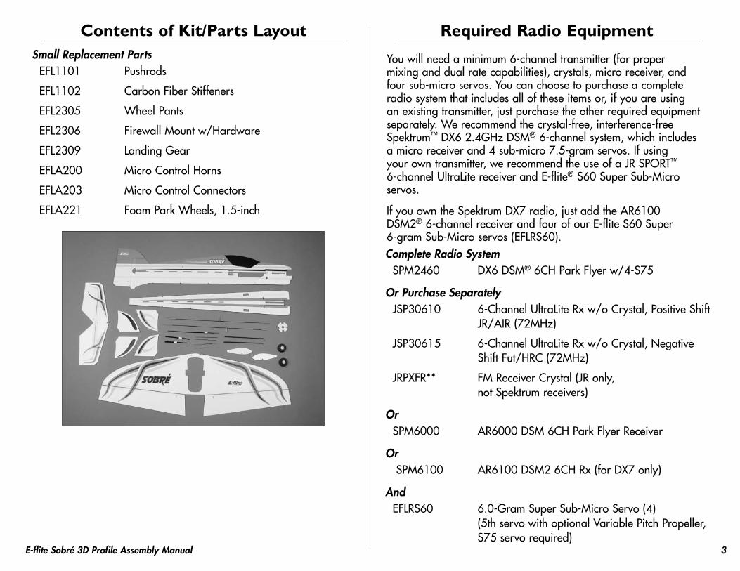
Contents of Kit/Parts LayoutSmall Replacement Parts
EFL1101 Pushrods
EFL1102 CarbonFiberStiffeners
EFL2305 WheelPants
EFL2306 FirewallMountw/Hardware
EFL2309 LandingGear
EFLA200 MicroControlHorns
EFLA203 MicroControlConnectors
EFLA221 FoamParkWheels,1.5-inch
Required Radio Equipment
Youwillneedaminimum6-channeltransmitter(forpropermixinganddualratecapabilities),crystals,microreceiver,andfoursub-microservos.Youcanchoosetopurchaseacompleteradiosystemthatincludesalloftheseitemsor,ifyouareusinganexistingtransmitter,justpurchasetheotherrequiredequipmentseparately.Werecommendthecrystal-free,interference-freeSpektrum™DX62.4GHzDSM®6-channelsystem,whichincludesamicroreceiverand4sub-micro7.5-gramservos.Ifusingyourowntransmitter,werecommendtheuseofaJRSPORT™6-channelUltraLitereceiverandE-flite®S60SuperSub-Microservos.
IfyouowntheSpektrumDX7radio,justaddtheAR6100DSM2®6-channelreceiverandfourofourE-fliteS60Super6-gramSub-Microservos(EFLRS60).Complete Radio System
SPM2460 DX6DSM®6CHParkFlyerw/4-S75
Or Purchase SeparatelyJSP30610 6-ChannelUltraLiteRxw/oCrystal,PositiveShift
JR/AIR(72MHz)
JSP30615 6-ChannelUltraLiteRxw/oCrystal,NegativeShiftFut/HRC(72MHz)
JRPXFR** FMReceiverCrystal(JRonly,notSpektrumreceivers)
OrSPM6000 AR6000DSM6CHParkFlyerReceiver
OrSPM6100 AR6100DSM26CHRx(forDX7only)
AndEFLRS60 6.0-GramSuperSub-MicroServo(4)
(5thservowithoptionalVariablePitchPropeller,S75servorequired)
� E-flite Sobré 3D Profile Assembly Manual
Outrunner SetupEFLM1150 Park300BrushlessOutrunnerMotor,1380Kv
EFLA1010 10-AmpProBrushlessESC
APC08038SF 8x3.8SlowFlyerProp
OrAPC09047SF 9x4.7SlowFlyerProp(GeorgeHickssetup)
THP4803SJPL 480mAh3-Cell11.1VLi-Po,JST
EFLC3005 Celectra™1–3CellLi-PoCharger
Note: If you want more power, substitute the recommended Park 300 BL Outrunner, 1380Kv (EFLM1150) with the Park 370 BL Outrunner, 1200Kv with 4mm Hollow Shaft (EFLM1210HS). This motor is not just for variable pitch props, it has great performance for this size model.
Variable Pitch Prop Outrunner SetupEFLPVPP100 ShowstopperPrecisionVariable
PitchPropSystem
EFLM1210HS Park370BLOutrunner,1200Kvw/4mmHollowShaft
EFLA1010 10-AmpProBrushlessESC
THP7303SJPL 730mAh3-Cell11.1VLi-Po,JST
EFLC3005 Celectra1–3CellLi-PoCharger
Optional AccessoriesEFLA110 PowerMeter
Alternative Cyclon Outrunner SetupCYLCPLR05 CYLCPLR05
EFLM1961 CarbonFiberTube,6",8mmOD,1/4"ID
EFLA1010 10-AmpProBrushlessESC
APC09038SF 9x3.8SlowFlyerProp
THP7303SJPL 730mAh3-Cell11.1VLi-Po,JST
EFLC3005 Celectra™1–3CellLi-PoCharger
Required Tools and AdhesivesTools & Equipment
EFLA250 ParkFlyerToolAssortment,5-piece
Or Purchase SeparatelyEFLA257 Screwdriver,#0Phillips(orincludedwith
EFLA250)
CardstockDrillDrillbit:1/16-inch(1.5mm)HobbyknifeFelt-tippedpenSidecuttersPliersStringSquareSandpaper
AdhesivesEFLA209 FoamCompatibleCA,Medium
EFLA207 FoamCompatibleActivator
LowTemperatureHotGlue

�E-flite Sobré 3D Profile Assembly Manual
Note on Lithium Polymer Batteries
LithiumPolymerbatteriesaresignificantlymorevolatilethanalkalineorNi-Cd/Ni-MHbatteriesusedinRCapplications.Allmanufacturer’sinstructionsandwarningsmustbefollowedclosely.MishandlingofLi-Pobatteriescanresultinfire.Alwaysfollowthemanufacturer’sinstructionswhendisposingofLithiumPolymerbatteries.
Warning
AnRCaircraftisnotatoy!Ifmisused,itcancauseseriousbodilyharmanddamagetoproperty.Flyonlyinopenareas,preferablyatAMA(AcademyofModelAeronautics)approvedflyingsites,followingallinstructionsincludedwithyourradio.
Keeplooseitemsthatcangetentangledinthepropellerawayfromtheprop,includinglooseclothing,orotherobjectssuchaspencilsandscrewdrivers.Especiallykeepyourhandsawayfromthepropeller.
Warranty Period
HorizonHobby,Inc.,(Horizon)warrantiesthattheProductspurchased(the“Product”)willbefreefromdefectsinmaterialsandworkmanshipatthedateofpurchasebythePurchaser.
Limited Warranty
(a)ThiswarrantyislimitedtotheoriginalPurchaser("Purchaser")andisnottransferable.REPAIRORREPLACEMENTASPROVIDEDUNDERTHISWARRANTYISTHEEXCLUSIVEREMEDYOFTHEPURCHASER.ThiswarrantycoversonlythoseProductspurchasedfromanauthorizedHorizondealer.Thirdpartytransactionsarenotcoveredbythiswarranty.Proofofpurchaseisrequiredforwarrantyclaims.Further,Horizonreservestherighttochangeormodifythiswarrantywithoutnoticeanddisclaimsallotherwarranties,expressorimplied.
(b)Limitations-HORIZONMAKESNOWARRANTYORREPRESENTATION,EXPRESSORIMPLIED,ABOUTNON-INFRINGEMENT,MERCHANTABILITYORFITNESSFORAPARTICULARPURPOSEOFTHEPRODUCT.THEPURCHASERACKNOWLEDGESTHATTHEYALONEHAVEDETERMINEDTHATTHEPRODUCTWILLSUITABLYMEETTHEREQUIREMENTSOFTHEPURCHASER’SINTENDEDUSE.
(c)PurchaserRemedy-Horizon'ssoleobligationhereundershallbethatHorizonwill,atitsoption,(i)repairor(ii)replace,anyProductdeterminedbyHorizontobedefective.Intheeventofadefect,thesearethePurchaser'sexclusiveremedies.Horizonreservestherighttoinspectanyandallequipmentinvolvedinawarrantyclaim.RepairorreplacementdecisionsareatthesolediscretionofHorizon.ThiswarrantydoesnotcovercosmeticdamageordamageduetoactsofGod,accident,misuse,abuse,negligence,commercialuse,ormodificationofortoanypartoftheProduct.Thiswarrantydoesnotcoverdamageduetoimproperinstallation,operation,maintenance,orattemptedrepairbyanyoneotherthanHorizon.ReturnofanygoodsbyPurchasermustbeapprovedinwritingbyHorizonbeforeshipment.

� E-flite Sobré 3D Profile Assembly Manual
Damage Limits
HORIZONSHALLNOTBELIABLEFORSPECIAL,INDIRECTORCONSEQUENTIALDAMAGES,LOSSOFPROFITSORPRODUCTIONORCOMMERCIALLOSSINANYWAYCONNECTEDWITHTHEPRODUCT,WHETHERSUCHCLAIMISBASEDINCONTRACT,WARRANTY,NEGLIGENCE,ORSTRICTLIABILITY.Further,innoeventshalltheliabilityofHorizonexceedtheindividualpriceoftheProductonwhichliabilityisasserted.AsHorizonhasnocontroloveruse,setup,finalassembly,modificationormisuse,noliabilityshallbeassumednoracceptedforanyresultingdamageorinjury.Bytheactofuse,setuporassembly,theuseracceptsallresultingliability.
IfyouasthePurchaseroruserarenotpreparedtoaccepttheliabilityassociatedwiththeuseofthisProduct,youareadvisedtoreturnthisProductimmediatelyinnewandunusedconditiontotheplaceofpurchase.
Law:TheseTermsaregovernedbyIllinoislaw(withoutregardtoconflictoflawprincipals).
Safety Precautions
ThisisasophisticatedhobbyProductandnotatoy.Itmustbeoperatedwithcautionandcommonsenseandrequiressomebasicmechanicalability.FailuretooperatethisProductinasafeandresponsiblemannercouldresultininjuryordamagetotheProductorotherproperty.ThisProductisnotintendedforusebychildrenwithoutdirectadultsupervision.TheProductmanualcontainsinstructionsforsafety,operationandmaintenance.Itisessentialtoreadandfollowalltheinstructionsandwarningsinthemanual,priortoassembly,setuporuse,inordertooperatecorrectlyandavoiddamageorinjury.
Questions, Assistance, and Repairs
Yourlocalhobbystoreand/orplaceofpurchasecannotprovidewarrantysupportorrepair.Onceassembly,setuporuseoftheProducthasbeenstarted,youmustcontactHorizondirectly.ThiswillenableHorizontobetteransweryourquestionsandserviceyouintheeventthatyoumayneedanyassistance.Forquestionsorassistance,[email protected],orcall877.504.0233tollfreetospeaktoaservicetechnician.
Inspection or Repairs
IfthisProductneedstobeinspectedorrepaired,pleasecallforaReturnMerchandiseAuthorization(RMA).PacktheProductsecurelyusingashippingcarton.Pleasenotethatoriginalboxesmaybeincluded,butarenotdesignedtowithstandtherigorsofshippingwithoutadditionalprotection.Shipviaacarrierthatprovidestrackingandinsuranceforlostordamagedparcels,asHorizon is not responsible for merchandise until it arrives and is accepted at our facility.AServiceRepairRequestisavailableatwww.horizonhobby.comonthe“Support”tab.Ifyoudonothaveinternetaccess,pleaseincludealetterwithyourcompletename,streetaddress,emailaddressandphonenumberwhereyoucanbereachedduringbusinessdays,yourRMAnumber,alistoftheincludeditems,methodofpaymentforanynon-warrantyexpensesandabriefsummaryoftheproblem.Youroriginalsalesreceiptmustalsobeincludedforwarrantyconsideration.Besureyourname,address,andRMAnumberareclearlywrittenontheoutsideoftheshippingcarton.
Warranty Inspection and Repairs
To receive warranty service, you must include your original sales receiptverifyingtheproof-of-purchasedate.Providedwarrantyconditionshavebeenmet,yourProductwillberepairedorreplacedfreeofcharge.RepairorreplacementdecisionsareatthesolediscretionofHorizonHobby.
�E-flite Sobré 3D Profile Assembly Manual
Non-Warranty Repairs
Should your repair not be covered by warranty the repair will be completed and payment will be required without notification or estimate of the expense unless the expense exceeds �0% of the retail purchase cost.Bysubmittingtheitemforrepairyouareagreeingtopaymentoftherepairwithoutnotification.Repairestimatesareavailableuponrequest.Youmustincludethisrequestwithyourrepair.Non-warrantyrepairestimateswillbebilledaminimumof½houroflabor.Inadditionyouwillbebilledforreturnfreight.Pleaseadviseusofyourpreferredmethodofpayment.Horizonacceptsmoneyordersandcashierschecks,aswellasVisa,MasterCard,AmericanExpress,andDiscovercards.Ifyouchoosetopaybycreditcard,pleaseincludeyourcreditcardnumberandexpirationdate.Anyrepairleftunpaidorunclaimedafter90dayswillbeconsideredabandonedandwillbedisposedofaccordingly.Please note: non-warranty repair is only available on electronics and model engines.
Electronicsandenginesrequiringinspectionorrepairshouldbeshippedtothefollowingaddress:
HorizonServiceCenter4105FieldstoneRoad
Champaign,Illinois61822
AllotherProductsrequiringwarrantyinspectionorrepairshouldbeshippedtothefollowingaddress:
HorizonProductSupport4105FieldstoneRoad
Champaign,Illinois61822
Please call 8��-�0�-0�33 with any questions or concerns regarding this product or warranty.
Safety, Precautions, and Warnings
Astheuserofthisproduct,youaresolelyresponsibleforoperatingitinamannerthatdoesnotendangeryourselfandothersorresultindamagetotheproductorthepropertyofothers.
Carefullyfollowthedirectionsandwarningsforthisandanyoptionalsupportequipment(chargers,rechargeablebatterypacks,etc.)thatyouuse.
Thismodeliscontrolledbyaradiosignalthatissubjecttointerferencefrommanysourcesoutsideyourcontrol.Thisinterferencecancausemomentarylossofcontrolsoitisnecessarytoalwayskeepasafedistanceinalldirectionsaroundyourmodel,asthismarginwillhelptoavoidcollisionsorinjury.
•Alwaysoperateyourmodelinanopenareaawayfromcars,traffic,orpeople.
•Avoidoperatingyourmodelinthestreetwhereinjuryordamagecanoccur.
•Neveroperatethemodeloutintothestreetorpopulatedareasforanyreason.
•Neveroperateyourmodelwithlowtransmitterbatteries.
•Carefullyfollowthedirectionsandwarningsforthisandanyoptionalsupportequipment(chargers,rechargeablebatterypacks,etc.)thatyouuse.
•Keepallchemicals,smallpartsandanythingelectricaloutofthereachofchildren.
•Moisturecausesdamagetoelectronics.Avoidwaterexposuretoallequipmentnotspecificallydesignedandprotectedforthispurpose.

8 E-flite Sobré 3D Profile Assembly Manual
Airframe AssemblyRequired Parts
VerticalfuselageHorizontalfuselageWingw/aileronsStabilizerw/elevatorsMotormount
Required Tools and AdhesivesFoam-compatibleCA,MediumFoam-compatibleaccelerator(canbeusedtospeedupcuretime)Square
1.Locatetheverticalandhorizontalfuselagepieces.Slidethehorizontalfuselageintotheverticalfuselagestartingattheopeningforthewing/radioequipment.Usecarenottodamageanyofthealignmenttabsontheverticalfuselage.
2.Locatethewingandslideitintotheverticalfuselageunderneaththehorizontalfuselage.Usecarenottodamageeithertheverticalorhorizontalfuselagepieces.
Hint: Fold one of the ailerons up and onto the wing to make it a little narrower to install into the fuselage. Push the wing past center to move the aileron back into position, then center the wing.

�E-flite Sobré 3D Profile Assembly Manual
3.Slidethehorizontalstabilizerintothefuselage,beingcarefulnottodamageanyofthealignmenttabs.Youmayneedtomovethehorizontalfuselageoutoftheverticalfuselageslightlytogetthestabilizerintoposition.
Note: Trim the hinge tape at the rear of the stabilizer to provide clearance of the alignment hole.
4.Alignthewingwiththehorizontalfuselage.Usefoam-compatibleCAtogluethewingtoONLYthehorizontalfuselage.
Hint: Use the holes for the aileron servos to aid in the alignment between the horizontal fuselage and wing.
Note: There are slots at the front and rear of the wing. Lightly lift the area and apply CA underneath for a greater gluing area.
Important: If you plan on using CA activator, make sure it is foam compatible. Many accelerators will destroy the foam used on this model.
10 E-flite Sobré 3D Profile Assembly Manual
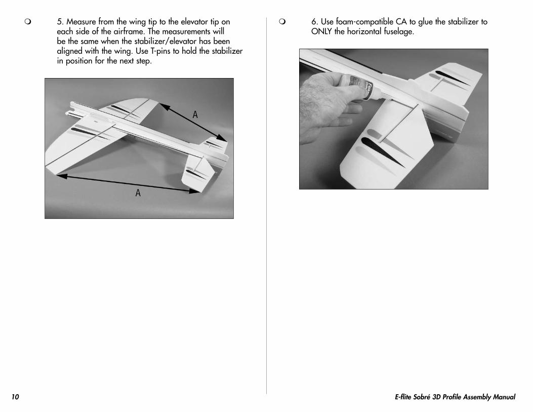
5.Measurefromthewingtiptotheelevatortiponeachsideoftheairframe.Themeasurementswillbethesamewhenthestabilizer/elevatorhasbeenalignedwiththewing.UseT-pinstoholdthestabilizerinpositionforthenextstep.
6.Usefoam-compatibleCAtogluethestabilizertoONLYthehorizontalfuselage.

11E-flite Sobré 3D Profile Assembly Manual
7.Placethemotormountinpositiontoaidinthealignmentoftheverticalandhorizontalfuselagepieces.DONOTgluethemountuntilinstructedtodoso.Positionthehorizontalandverticalfuselagepiecesuntilthemountrestsflushagainstboth.
8.Applyfoam-compatibleCAtothejointbetweentheverticalandhorizontalfuselagepiecesfromtheleadingedgeofthewingtothefrontofthefuselage.Useasquaretomakesurethetwopiecesarealigned.ApplyCAtoboththetopandbottomoftheverticalfuselage.
9.Completegluingtheverticalandhorizontalfuselagepiecestogether.Continuetouseasquaretokeepbothpiecesinalignment.

1� E-flite Sobré 3D Profile Assembly Manual
Installing the BracingRequired Parts
AssembledairframeCarbonrod,4.6-inch(117mm)(2)Carbonrod,5.9-inch(150mm)(2)Carbonrod,4.3-inch(110mm)(2)Carbonrod,3.9-inch(100mm)(4)Carbonrod,3.75-inch(95mm)(4)Carbonrod,12.7-inch(323mm)(2)Carbonrod,12-inch(305mm)(2)
Required Tools and AdhesivesFoam-compatibleCA,MediumSandpaperHobbyknifeSidecuttersEyeprotection
Note: It is important that each carbon rod attaches to the next, and to the carbon blade spars on the edges of the foam. This is necessary to provide the stiffest airframe possible.
1.Locatethetwo4.6-inch(117mm)carbonrods.Passtherodsthroughthefinandstabilizer.Butttherodstogetherinthefinandusefoam-compatibleCAtogluetherodstothefinONLYatthistime.
2.Useasquaretoalignthestabilizerwiththefin.Oncethefinisperpendiculartothestabilizer,useFoam-compatibleCAtogluethecarbonrodtothestabilizer.Squareeachsidebeforegluingtherodonthatparticularside.

13E-flite Sobré 3D Profile Assembly Manual
3.Positionthecarbonrodsinthefuselage,gluingtherodstotheverticalfuselageONLY.Thiswillallowforalignmentofthefuselageinthenextstep.
Note: The length of the rods are: XL = 5.9-inch (150mm) L = 4.3-inch (110mm) M = 3.9-inch (100mm) S = 3.75-inch (95mm)
4.Withtheairframeupright,checkthatthestabilizerisparalleltothewing.Lightlytwistthefuselageasnecessaryforalignment.
5.Usesidecutterstotrimanyexcesscarbonrodsthatextendbeyondthetopofthehorizontalfuselage.Withtherodsrestingtightlyagainstthecarbonspineandeachother,usefoam-compatibleCAtogluetheintersectionoftherodstothecarbonbladespars.

1� E-flite Sobré 3D Profile Assembly Manual
Important: Make sure to use eye protection when cutting the carbon rods.
6.Installingthewingbracingissimilartoinstallingthefuselagebracing,asyouwanttherodstobegluedtothecarbonbracingthathasbeenpre-installedonthewingandfuselage.Thelonger12.7-inch(323mm)rodispositionedtowardtheaileron,whiletheshorter12-inch(305mm)rodistowardtheleadingedge.Therodsarestaggeredandfitintonotchesinthefuselage.Makesuretherodsarestraightandarenotflexingthewing.UseFoam-compatibleCAtogluetherodsinposition.Thewingshouldbeflatandparalleltothehorizontalstabilizer,whilealsobeingperpendiculartotheverticalfuselage.Usesidecutterstotrimawayanyexcesscarbnrod.
Radio InstallationRequired Parts
AirframeServos(4)Microcontrolconnector(4)Controlconnectorbackplate(4)Microcontrolhorn(4)Controlhornbackplate(4)2mmx4mmscrew(4)Aileronpushrods,4.5-inch(115mm)(2)Rudderpushrod,19.25-inch(490mm)Elevatorpushrod,18.5-inch(470mm)Hookandloopmaterial
Required Tools and AdhesivesFoam-compatibleCA,MediumLow-temperaturehotglueDrillbit:
1/16-inch(1.5mm)Screwdriver,#0Phillips
1.Installthemicrocontrolhornontheaileronusingthecontrolhornbackplate.UseacoupledropsofFoam-compatibleCAtokeepthebackplateinposition.

1�E-flite Sobré 3D Profile Assembly Manual
2.Installtheelevatormicrocontrolhornsatthistime.Makesuretherudderhornextendsoppositeoftheelevatorhorn.
3.Installtheruddermicrocontrolhornsatthistimeaswell.Makesuretherudderhornextendsoppositeoftheelevatorhorn.
4.Removetheservoarmsfromthefourservos.Drilla1/16-inch(1.5mm)holeintheendofallfouroftheservoarms.
Note: We then suggest using the longest servo arms available for your servo to help achieve maximum control throws for 3D flying.
5.Slideamicrocontrolconnectorintotheholedrilledinthepreviousstep.Securetheconnectorusingacontrolconnectorbackplatefromtheoppositesideoftheconnector.Repeatforallfourservoarms.
Note: The connectors will face out away from the servo when installed. Remove any unused sides or portions of the servo arms.

1� E-flite Sobré 3D Profile Assembly Manual
6.Plugtheservosintothereceiver.Turnonthetransmitterandreceiverandchecktheoperationoftheservos.Aftercenteringthetrimsandsub-trims,attachtheservoarmsasshown.Notethedirectionofthearmsontheservos.
7.Usehotgluetoinstalltheaileronservos.
Note: The servo arms face toward the tips of the wing and the output shaft of the servo is toward the leading edge of the wing.
Note: Position the aileron servo arm parallel to the aileron hinge line.
8.Installtherudderandelevatorservosusinghotglue.Theoutputshaftsofbothservosfacethefrontoftheaircraft.
1�E-flite Sobré 3D Profile Assembly Manual
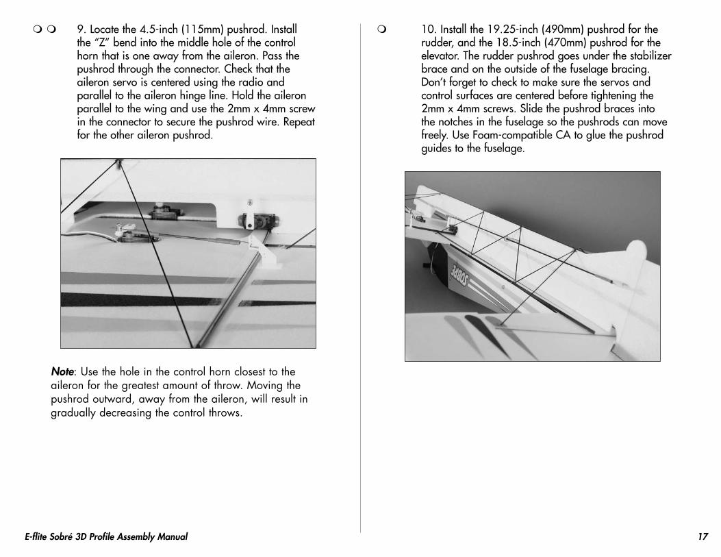
9.Locatethe4.5-inch(115mm)pushrod.Installthe“Z”bendintothemiddleholeofthecontrolhornthatisoneawayfromtheaileron.Passthepushrodthroughtheconnector.Checkthattheaileronservoiscenteredusingtheradioandparalleltotheaileronhingeline.Holdtheaileronparalleltothewingandusethe2mmx4mmscrewintheconnectortosecurethepushrodwire.Repeatfortheotheraileronpushrod.
Note: Use the hole in the control horn closest to the aileron for the greatest amount of throw. Moving the pushrod outward, away from the aileron, will result in gradually decreasing the control throws.
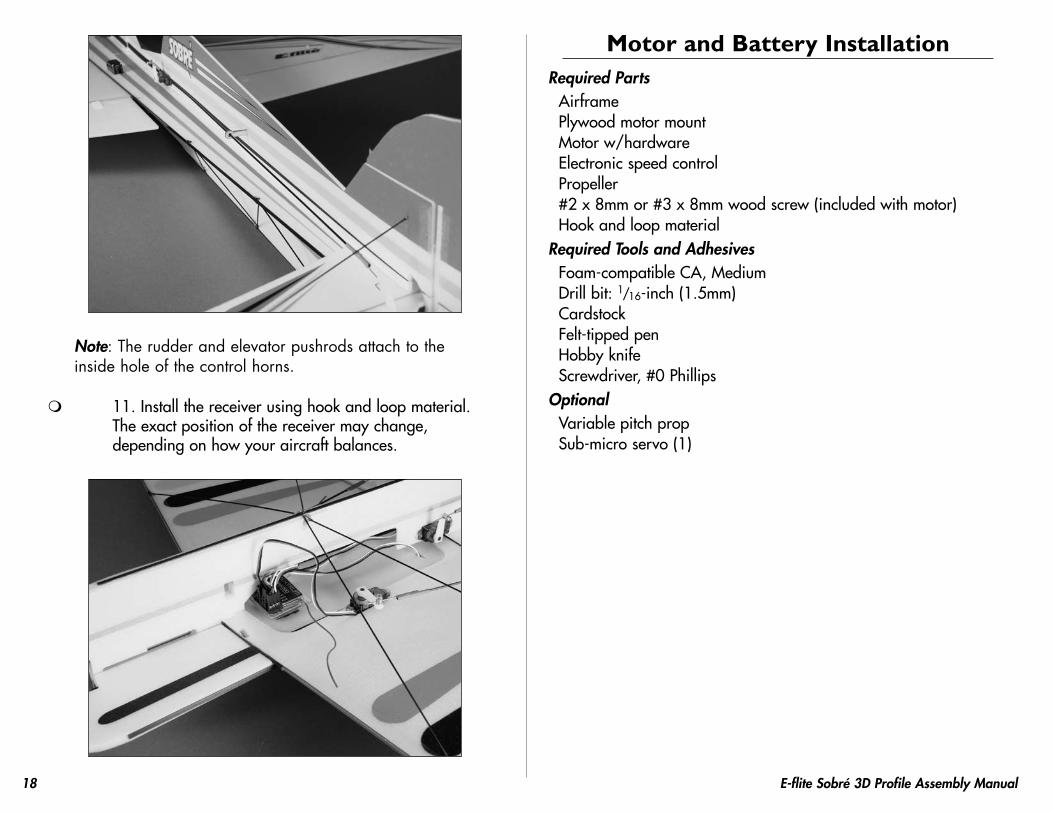
10.Installthe19.25-inch(490mm)pushrodfortherudder,andthe18.5-inch(470mm)pushrodfortheelevator.Therudderpushrodgoesunderthestabilizerbraceandontheoutsideofthefuselagebracing.Don’tforgettochecktomakesuretheservosandcontrolsurfacesarecenteredbeforetighteningthe2mmx4mmscrews.Slidethepushrodbracesintothenotchesinthefuselagesothepushrodscanmovefreely.UseFoam-compatibleCAtogluethepushrodguidestothefuselage.
18 E-flite Sobré 3D Profile Assembly Manual
Note: The rudder and elevator pushrods attach to the inside hole of the control horns.
11.Installthereceiverusinghookandloopmaterial.Theexactpositionofthereceivermaychange,dependingonhowyouraircraftbalances.
Motor and Battery InstallationRequired Parts
AirframePlywoodmotormountMotorw/hardwareElectronicspeedcontrolPropeller#2x8mmor#3x8mmwoodscrew(includedwithmotor)Hookandloopmaterial
Required Tools and AdhesivesFoam-compatibleCA,MediumDrillbit:1/16-inch(1.5mm)CardstockFelt-tippedpenHobbyknifeScrewdriver,#0Phillips
OptionalVariablepitchpropSub-microservo(1)
1�E-flite Sobré 3D Profile Assembly Manual
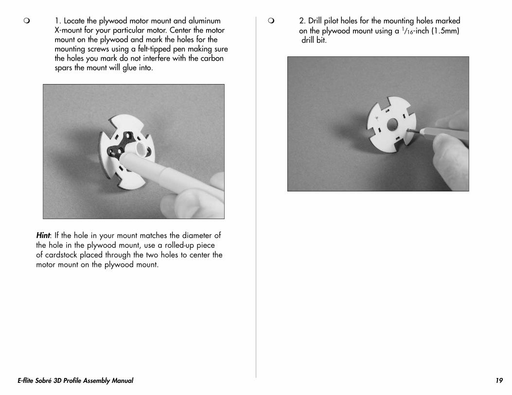
1.LocatetheplywoodmotormountandaluminumX-mountforyourparticularmotor.Centerthemotormountontheplywoodandmarktheholesforthemountingscrewsusingafelt-tippedpenmakingsuretheholesyoumarkdonotinterferewiththecarbonsparsthemountwillglueinto.
Hint: If the hole in your mount matches the diameter of the hole in the plywood mount, use a rolled-up piece of cardstock placed through the two holes to center the motor mount on the plywood mount.
2.Drillpilotholesforthemountingholesmarkedontheplywoodmountusinga1/16-inch(1.5mm)drillbit.

�0 E-flite Sobré 3D Profile Assembly Manual
3.Repositiontheshaftonthemotorasshowntoallowtheuseofthepropelleradapter.Makesuretosecuretheshaftusinginstructionsincludedwithyourmotor.
4.Attachthemounttoyourparticularmotor.
5.Attachthemotortotheplywoodmountusingtwo#2x8mmwoodscrewsortwo#3x8mmwoodscrews.
�1E-flite Sobré 3D Profile Assembly Manual
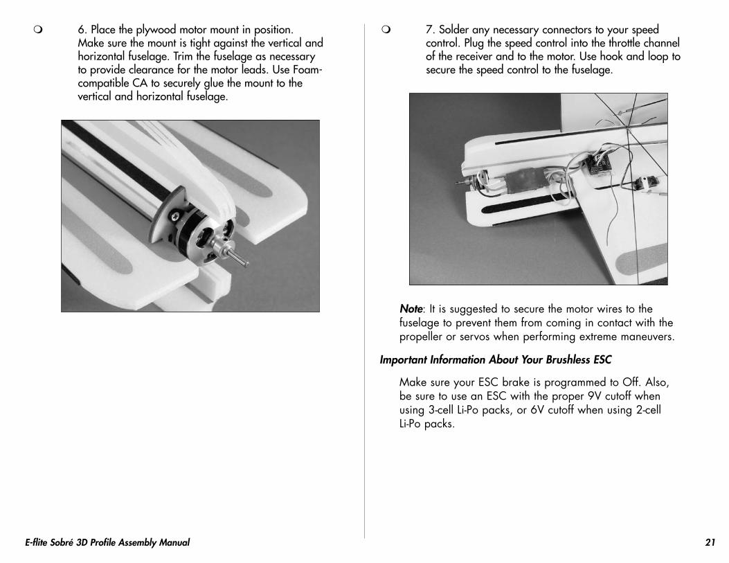
6.Placetheplywoodmotormountinposition.Makesurethemountistightagainsttheverticalandhorizontalfuselage.Trimthefuselageasnecessarytoprovideclearanceforthemotorleads.UseFoam-compatibleCAtosecurelygluethemounttotheverticalandhorizontalfuselage.
7.Solderanynecessaryconnectorstoyourspeedcontrol.Plugthespeedcontrolintothethrottlechannelofthereceiverandtothemotor.Usehookandlooptosecurethespeedcontroltothefuselage.
Note: It is suggested to secure the motor wires to the fuselage to prevent them from coming in contact with the propeller or servos when performing extreme maneuvers.
Important Information About Your Brushless ESC
Make sure your ESC brake is programmed to Off. Also, be sure to use an ESC with the proper 9V cutoff when using 3-cell Li-Po packs, or 6V cutoff when using 2-cell Li-Po packs.

�� E-flite Sobré 3D Profile Assembly Manual
8.Turnonthetransmitterandbringthethrottletrimandsticktothelowthrottleposition.Plugthebatteryintothespeedcontrolandchecktheoperationofthemotor.Itshouldrotatecounterclockwisewhenviewedfromthefrontoftheaircraft.UsetheinstructionsprovidedwithyourESCtomakecorrectionstothedirectionofrotationofthemotorifnecessary.
Note: Never check the motor rotation on the bench with the propeller installed. The plane could move and cause serious injury. Always check the motor without the propeller to avoid injury.
9.Installthepropellerusingtheinstructionsprovidedwithyourmotororpropellersystem.
Important Information About Your Propeller
It is very important to check to be sure the propeller is balanced before installing on the propeller shaft. An unbalanced propeller may damage the motor, airframe and other components, or cause poor flight and performance characteristics.
Note: If it is necessary to enlarge the hole in the propeller, make sure to check the balance of the propeller afterwards.
�3E-flite Sobré 3D Profile Assembly Manual
Optional Variable Pitch Prop Installation
Note: The following outlines the installation of a VPP for your Sobré. Be sure to consult the manual for your chosen variable pitch prop unit before proceeding with installation of the pitch servo and linkage. Due to the variety of VPP systems available, there may be some variation in how the servo and linkage can be installed.
Installthemotorandmountasdescribedintheprevioussection.Youwillhavetotrimthefuselagetoallowforclearanceofthecontrollinkageandservo.
1.Installthepitchservoasshown.Takeyourtimetomakesuretheservohornandlinkagedoesnotbindagainstthefuselage.Alsocheckthatthelinkageisnotbeingputunderaloadwhenconnected.Useahobbyknifetoremoveanyportionsofthefuselagethatcausebinding.Usefoam-compatibleCAorhotgluetosecuretheservotothefuselage.
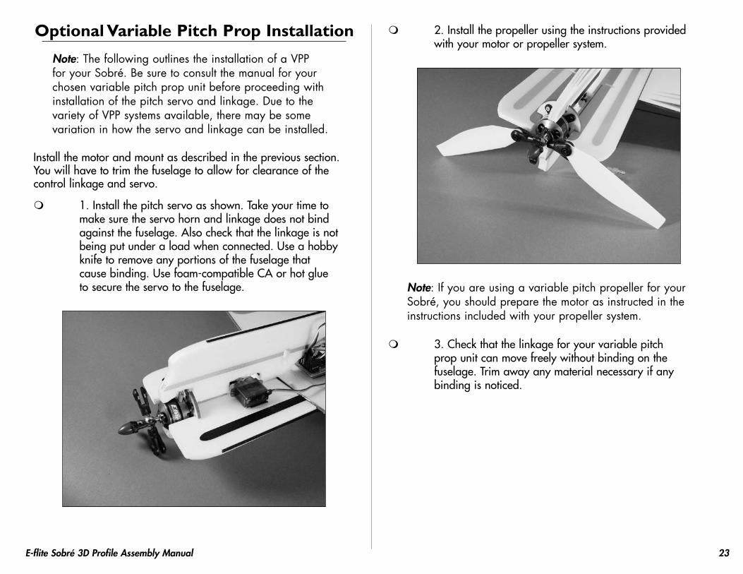
2.Installthepropellerusingtheinstructionsprovidedwithyourmotororpropellersystem.
Note: If you are using a variable pitch propeller for your Sobré, you should prepare the motor as instructed in the instructions included with your propeller system.
3.Checkthatthelinkageforyourvariablepitchpropunitcanmovefreelywithoutbindingonthefuselage.Trimawayanymaterialnecessaryifanybindingisnoticed.
�� E-flite Sobré 3D Profile Assembly Manual
Landing Gear InstallationRequired Parts
AirframeLandinggearstrut(2)Wheelretainer(4)Wheelpant(2)1.5-inch(38mm)foamwheel(2)Landinggearsupportdisk(2)
Required Tools and AdhesivesFoam-compatibleCA
The landing gear is optional. If you plan on saving weight, or flying from very rough surfaces, it is suggested to skip this section.
1.Locatethelandinggearstrut,twowheelretainersandthewheel.UseFoam-compatibleCAtoinstallthewheelretainerontothestrut.Theretainerswillsandwichthewheelinposition.
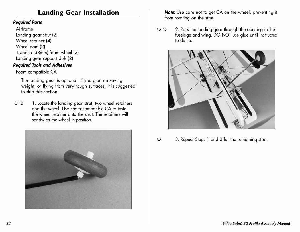
Note: Use care not to get CA on the wheel, preventing it from rotating on the strut.
2.Passthelandinggearthroughtheopeninginthefuselageandwing.DONOTuseglueuntilinstructedtodoso.
3.RepeatSteps1and2fortheremainingstrut.

��E-flite Sobré 3D Profile Assembly Manual
4.Thestrutsshouldextendroughly3/32-inch(2.5mm)throughthetopofthewing.Thiswillgivethelandinggearsupportdisksplentyofstruttoattachto.
Hint: You can just drop the disks into position and check to make sure the strut extends beyond the disk instead of measuring it.
5.Checkthatthewheelsareparallelorhaveslighttoe-in.Usefoam-compatibleCAtogluethestrutstothefuselageandeachother.Makesurethewingissittingparalleltothegroundsothewheelsarelocatedatthesameheight.
6.Installthelandinggearsupportdisksusingfoam-compatibleCA.Makesuretogluethediskssecurelytoboththehorizontalfuselageandlandinggearstruts.
7.Usefoam-compatibleCAtogluethewheelpantstothewheelretainers.Makesurethepantsarepositionedsotheywon’tdragonthegroundduringtakeoffandlandingbeforeapplyingtheCA.
�� E-flite Sobré 3D Profile Assembly Manual
Installing the Optional Side Force Generators
Required PartsSideforcegenerator(upper)(2)Sideforcegenerator(lower)(2)Carbonrod,4.3-inch(110mm)(4)
Required Tools and AdhesivesFoam-compatibleCASquare
Note: The side force generator (SFG) installation is optional. If you plan on saving weight, or flying from very rough surfaces, it is suggested to skip this section.
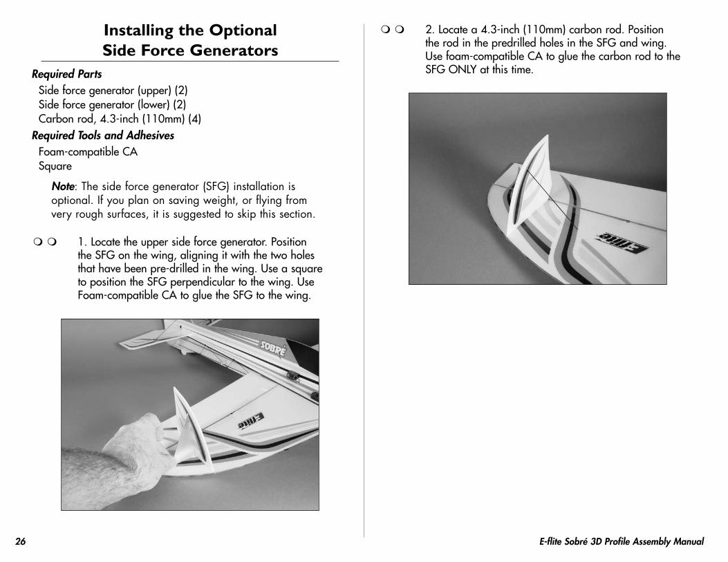
1.Locatetheuppersideforcegenerator.PositiontheSFGonthewing,aligningitwiththetwoholesthathavebeenpre-drilledinthewing.UseasquaretopositiontheSFGperpendiculartothewing.UseFoam-compatibleCAtogluetheSFGtothewing.
2.Locatea4.3-inch(110mm)carbonrod.PositiontherodinthepredrilledholesintheSFGandwing.Usefoam-compatibleCAtogluethecarbonrodtotheSFGONLYatthistime.
��E-flite Sobré 3D Profile Assembly Manual
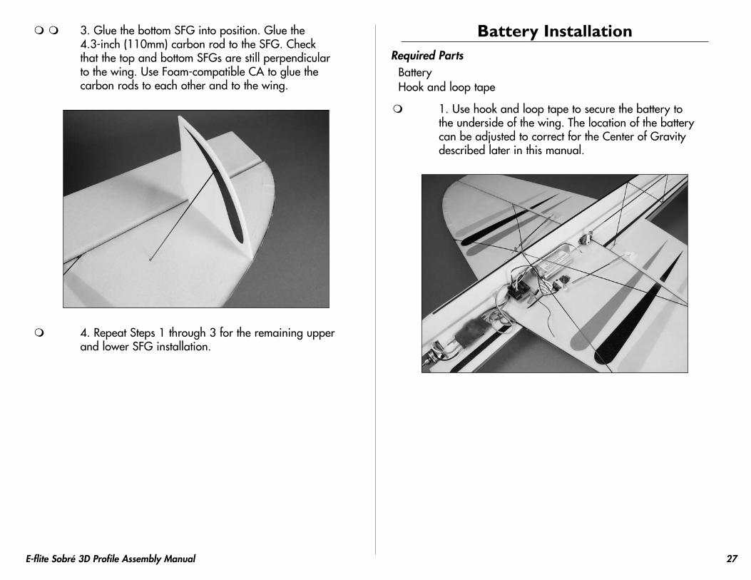
3.GluethebottomSFGintoposition.Gluethe4.3-inch(110mm)carbonrodtotheSFG.CheckthatthetopandbottomSFGsarestillperpendiculartothewing.UseFoam-compatibleCAtogluethecarbonrodstoeachotherandtothewing.
4.RepeatSteps1through3fortheremainingupperandlowerSFGinstallation.
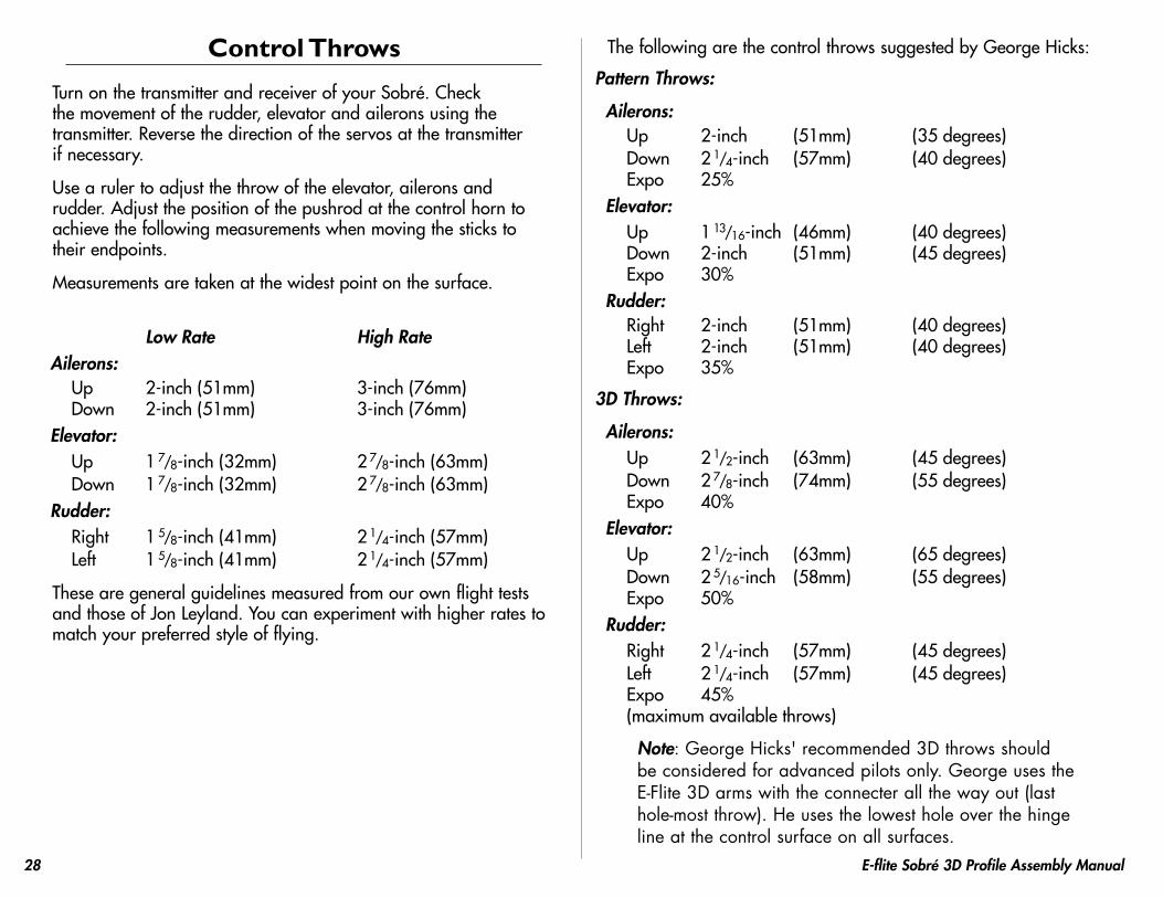
Battery InstallationRequired Parts
BatteryHookandlooptape
1.Usehookandlooptapetosecurethebatterytotheundersideofthewing.ThelocationofthebatterycanbeadjustedtocorrectfortheCenterofGravitydescribedlaterinthismanual.
�8 E-flite Sobré 3D Profile Assembly Manual
Control Throws
TurnonthetransmitterandreceiverofyourSobré.Checkthemovementoftherudder,elevatorandaileronsusingthetransmitter.Reversethedirectionoftheservosatthetransmitterifnecessary.
Usearulertoadjustthethrowoftheelevator,aileronsandrudder.Adjustthepositionofthepushrodatthecontrolhorntoachievethefollowingmeasurementswhenmovingthestickstotheirendpoints.
Measurementsaretakenatthewidestpointonthesurface.
Low Rate High RateAilerons:
Up 2-inch(51mm) 3-inch(76mm)Down 2-inch(51mm) 3-inch(76mm)
Elevator:Up 1
7/8-inch(32mm) 27/8-inch(63mm)
Down 17/8-inch(32mm) 2
7/8-inch(63mm)Rudder:
Right 15/8-inch(41mm) 2
1/4-inch(57mm)Left 1
5/8-inch(41mm) 21/4-inch(57mm)
ThesearegeneralguidelinesmeasuredfromourownflighttestsandthoseofJonLeyland.Youcanexperimentwithhigherratestomatchyourpreferredstyleofflying.
ThefollowingarethecontrolthrowssuggestedbyGeorgeHicks:
Pattern Throws:
Ailerons:Up 2-inch (51mm) (35degrees)Down 2
1/4-inch (57mm) (40degrees)Expo 25%
Elevator:Up 1
13/16-inch (46mm) (40degrees)Down 2-inch (51mm) (45degrees)Expo 30%
Rudder:Right 2-inch (51mm) (40degrees)Left 2-inch (51mm) (40degrees)Expo 35%
3D Throws:
Ailerons:Up 2
1/2-inch (63mm) (45degrees)Down 2
7/8-inch (74mm) (55degrees)Expo 40%
Elevator:Up 2
1/2-inch (63mm) (65degrees)Down 2
5/16-inch (58mm) (55degrees)Expo 50%
Rudder:Right 2
1/4-inch (57mm) (45degrees)Left 2
1/4-inch (57mm) (45degrees)Expo 45%(maximumavailablethrows)
Note: George Hicks' recommended 3D throws should be considered for advanced pilots only. George uses the E-Flite 3D arms with the connecter all the way out (last hole-most throw). He uses the lowest hole over the hinge line at the control surface on all surfaces.

��E-flite Sobré 3D Profile Assembly Manual
Center of GravityCaution: Do not inadvertently skip this step!
TherecommendedCenterofGravity(CG)locationfortheSobréis3
1/2-inch(89mm)behindthecenteroftheleadingedgeofthewingagainstthefuselage.Afterthefirstflights,theCGpositioncanbeadjustedforyourpersonalpreference.
Note: George Hicks CG location is 4-inch (100mm)
Range Testing the Radio
1.Besuretorangecheckyourradiobeforeeachflyingsession.Thisisaccomplishedbyturningonyourtransmitterwiththeantennacollapsed.Turnonthereceiverinyourairplane.Withyourairplaneonthegroundandtheenginerunning,youshouldbeabletowalk30paces(approximately100feet)awayfromyourairplaneandstillhavecompletecontrolofallfunctions.Ifnot,don’tattempttofly!Haveyourradioequipmentcheckedoutbythemanufacturer.
2.Double-checkthatallcontrols(aileron,elevator,rudderandthrottle)moveinthecorrectdirection.
3.Besurethatyourtransmitterbatteriesarefullycharged,pertheinstructionsincludedwithyourradio.

30 E-flite Sobré 3D Profile Assembly Manual
PreflightCheck Your Radio
Beforegoingtothefield,besurethatyourbatteriesarefullychargedpertheinstructionsincludedwithyourradio.Chargeboththetransmitterandreceiverpackforyourairplane.Usetherecommendedchargersuppliedwithyourparticularradiosystem,followingtheinstructionsprovidedwiththeradio.Inmostcases,theradioshouldbechargedthenightbeforegoingoutflying.
Beforeeachflyingsession,besuretorangecheckyourradio.Seeyourradiomanualfortherecommendedrangeandinstructionsforyourradiosystem.Eachradiomanufacturerspecifiesdifferentproceduresfortheirradiosystems.Next,startthemotor.Withthemodelsecurelyanchored,checktherangeagain.Therangetestshouldnotbesignificantlyaffected.Ifitis,don’tattempttofly!Haveyourradioequipmentcheckedoutbythemanufacturer.
Note: Keep loose items that can get entangled in the propeller away from the prop. These include loose clothing, or other objects such as pencils and screwdrivers. Especially keep your hands away from the propeller.
Double-checkthatallcontrols(aileron,elevator,rudderandthrottle)moveinthecorrectdirection.
Checktheradioinstallationandmakesureallthecontrolsurfacesaremovingcorrectly(i.e.thecorrectdirectionandwiththerecommendedthrows).Testrunthemotorandmakesureittransitionssmoothlyfromofftofullthrottleandback.Alsoensuretheengineisinstalledaccordingtothemanufacturer’sinstructions,anditwilloperateconsistently.
Checkallthecontrolhorns,servohorns,andclevisestomakesuretheyaresecureandingoodcondition.Replaceanyitemsthatwouldbeconsideredquestionable.Failureofanyofthesecomponentsinflightwouldmeanthelossofyouraircraft.
Flying the Sobré
FlyingtheSobréisaboutasfunasitcangetatthepark.Averylightwingloadingandextremecontrolthrowsmakeforsomeexciting3Dflying.VerifythatyourCGisatthecorrectlocationasperthemanualandthatyouhaveyourratessetuptoyourliking.Verifythatallcontrolthrowsareinthecorrectdirectionandthemotorspinsinthecorrectdirectionaswell.
Pointthemodelintothewindandaddsomethrottletrimuntilthemotorbeginstoturn.Thiswillbeyourflightidle.Now,applypowerslowly.Youwillfindthemodelwillbecomeairborneveryquicklyandatalowspeed.Thismodelexcelsatflyingslowandeasy,aswellasslowandextreme.Trimthemodelforlevelflightathalfthrottle.Onlyusefullthrottleformaneuvering.Donotflythismodelfastoratfullthrottleinlevelflight.Doingthiswillresultintheflightcontrolsflutteringandapotentialcatastrophicfailureoftheairframe.
YouwillfindyoucanadjusttheCGtoyourlikingbymovingthebatterypackforeoraftonthewing.
TolandtheSobréjustreducethethrottletoidleandfeedinupelevatoruntilthemodelsettlesintoaslightlynosehighattitude.Gentlyflythemodeldowntothelandingspotwithafinalflairattouchdown.Youwillfindthemodelwillhaveaveryshortrollout.WehopeyouenjoytheSobréasmuchaswedo.
Happylandings.
31E-flite Sobré 3D Profile Assembly Manual
2007 Official AMA National Model Aircraft Safety Code
GENERAL1) Iwillnotflymymodelaircraftinsanctionedevents,airshows
ormodelflyingdemonstrationsuntilithasbeenproventobeairworthybyhavingbeenpreviously,successfullyflighttested.
2) Iwillnotflymymodelhigherthanapproximately400feetwithin3milesofanairportwithoutnotifyingtheairportoperator.Iwillgiveright-of-wayandavoidflyingintheproximityoffull-scaleaircraft.Wherenecessary,anobservershallbeutilizedtosuperviseflyingtoavoidhavingmodelsflyintheproximityoffull-scaleaircraft.
3) Whereestablished,IwillabidebythesafetyrulesfortheflyingsiteIuse,andIwillnotwillfullyordeliberatelyflymymodelsinacareless,recklessand/ordangerousmanner.
4) Themaximumtakeoffweightofamodelis55pounds,exceptmodelsflownunderExperimentalAircraftrules.
5) IwillnotflymymodelunlessitisidentifiedwithmynameandaddressorAMAnumberonorinthemodel.(Thisdoesnotapplytomodelswhilebeingflownindoors.)
6) Iwillnotoperatemodelswithmetal-bladedpropellersorwithgaseousboosts,inwhichgasesotherthanairentertheirinternalcombustionengine(s);norwillIoperatemodelswithextremelyhazardousfuelssuchasthosecontainingtetranitromethaneorhydrazine.
RADIO CONTROL1) Iwillhavecompletedasuccessfulradioequipmentgroundrange
checkbeforethefirstflightofaneworrepairedmodel.2) IwillnotflymymodelaircraftinthepresenceofspectatorsuntilI
becomeaqualifiedflier,unlessassistedbyanexperiencedhelper.3) Atallflyingsitesastraightorcurvedline(s)mustbeestablished
infrontofwhichallflyingtakesplacewiththeothersideforspectators.Onlypersonnelinvolvedwithflyingtheaircraftareallowedatorinfrontoftheflightline.Intentionalflyingbehindtheflightlineisprohibited.
4) IwilloperatemymodelusingonlyradiocontrolfrequenciescurrentlyallowedbytheFederalCommunicationsCommission.(OnlyproperlylicensedAmateursareauthorizedtooperateequipmentonAmateurBandfrequencies.)
5) Flyingsitesseparatedbythreemilesormoreareconsideredsafefromsite-to-siteinterference,evenwhenbothsitesusethesamefrequencies.Anycircumstancesunderthreemilesseparationrequireafrequencymanagementarrangement,whichmaybeeitheranallocationofspecificfrequenciesforeachsiteortestingtodeterminethatfreedomfrominterferenceexists.AllocationplansorinterferencetestreportsshallbesignedbythepartiesinvolvedandprovidedtoAMAHeadquarters.
Documentsofagreementandreportsmayexistbetween(1)twoormoreAMACharteredClubs,(2)AMAclubsandindividualAMAmembersnotassociatedwithAMAClubs,or(3)twoormoreindividualAMAmembers.
6) ForCombat,distancebetweencombatengagementlineandspectatorlinewillbe500feetpercubicinchofenginedisplacement.(Example:.40engine=200feet.);electricmotorswillbebasedonequivalentcombustionenginesize.AdditionalsafetyrequirementswillbepertheRCCombatsectionofthecurrentCompetitionRegulations.
7) Atairshowsormodelflyingdemonstrations,asinglestraightlinemustbeestablished,onesideofwhichisforflying,withtheothersideforspectators.
8) WiththeexceptionofeventsflownunderAMACompetitionrules,afterlaunch,exceptforpilotsorhelpersbeingused,nopoweredmodelmaybeflowncloserthan25feettoanyperson.
9) Undernocircumstancesmayapilotorotherpersontouchapoweredmodelinflight.

10���
©2007HorizonHobby,Inc.4105FieldstoneRoad
Champaign,Illinois61822(877)504-0233
horizonhobby.com E-fliteRC.com