so before we dive in, i just want to clarify what we mean
TRANSCRIPT

1

Hi! I’m Jan-Harald. This is joint work with Marius, Sam, and Sandeep. The bulk of this presentation was prepared by Marius, who is unfortunately not able to attend this conference, so I’ll do my best to cover in his absence. So before we dive in, I just want to clarify what we mean by “Tile Local Storage”. As you probably know, tile-based GPUs are very common* in mobile. What these GPUs have in common is that they split the framebuffer processing into multiple regions, called tiles, that are processed one at the time. As part of this they will have some amount of on-chip memory that is used to store color, depth, and stencil values for the tile that is being processed. The obvious benefit of this approach is that there is no need to write to external memory (main memory) for every fragment that is processed. Instead, all writes go to the on-chip buffer until all processing for the tile is completed and then the contents of the entire tile is written back to memory. It is this on-chip memory we refer to as Tile Local Storage (TLS). During normal rendering, TLS contents are typically loaded/stored to/from main memory whenever you begin/end rendering a tile – but it’s possible to deviate from this. The memory can instead be exposed more directly and the loading/storing can be managed explicitly. Today we’ll look at how TLS and the various extensions that expose it can be used to do efficient deferred rendering and approximate order-independent transparency. We’ll also spend some time examining where this technology could go next. * (Side note – actually the vast majority of all GPUs in the world are tile-based due to the massive volumes mobile GPUs ship in!)
2
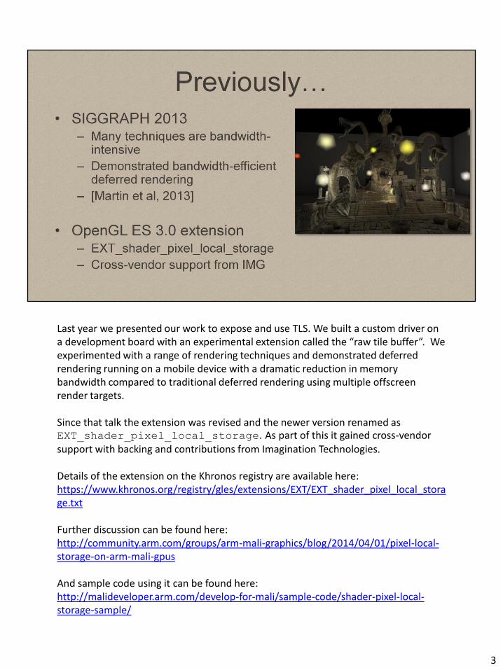
Last year we presented our work to expose and use TLS. We built a custom driver on a development board with an experimental extension called the “raw tile buffer”. We experimented with a range of rendering techniques and demonstrated deferred rendering running on a mobile device with a dramatic reduction in memory bandwidth compared to traditional deferred rendering using multiple offscreen render targets. Since that talk the extension was revised and the newer version renamed as EXT_shader_pixel_local_storage. As part of this it gained cross-vendor support with backing and contributions from Imagination Technologies. Details of the extension on the Khronos registry are available here: https://www.khronos.org/registry/gles/extensions/EXT/EXT_shader_pixel_local_storage.txt Further discussion can be found here: http://community.arm.com/groups/arm-mali-graphics/blog/2014/04/01/pixel-local-storage-on-arm-mali-gpus And sample code using it can be found here: http://malideveloper.arm.com/develop-for-mali/sample-code/shader-pixel-local-storage-sample/
3
A couple of other things has also happened since our presentation last year. An existing extension, EXT_framebuffer_fetch, was also updated to support MRTs and more flexible precision controls and now also enables access to TLS when used on an OpenGL ES 3.0 device. However, it does not have the same set of functionality as PLS. In this talk we will compare and contrast the two extensions. Recently, Apple announced a new low level graphics API, “Metal”. This API also exposes some features related to TLS that we will mention later.
4

So today we will: - Look at these extensions in more detail, and compare/contrast their feature sets - We’ll look at how bandwidth-efficient deferred rendering can be achieved with
these extensions. - Then look at how approximate order-independent transparency (AOIT) can be
adapted to use TLS. We’ll look at several possible implementations based on pixel local storage and how these techniques compare in terms of quality and efficiency.
- Pixel local storage is unique in that it allows more flexible chaining of techniques without going “off-chip”. We will show how deferred rendering was combined with AOIT in a single render pass.
- We’ll then conclude by looking at possible improvements of the technology and future work.
5
6

Let’s take a closer look at framebuffer fetch extensions (FBF). The EXT_shader_framebuffer_fetch extension differs between versions. OpenGL ES 2.0 didn’t support MRTs or int formats so framebuffer readback was quite limited and couldn’t be used for techniques like deferred shading. It was primarily useful for programmable blending. The extension was updated to work against OpenGL ES 3.0. At this point MRTs, integer formats and the ability to override the default mediump precision qualifier enabled it to support deferred rendering. It is commonly available on iOS for A7-based devices. In both cases EXT_shader_framebuffer_fetch allows you to readback the framebuffer, but not the depth or stencil values. To readback depth it must be stored in one of the MRTs at sufficient precision. MSAA framebuffers are supported but are expensive. There are other closely related framebuffer readback extensions: - ARM_shader_framebuffer_fetch provided an alternative to the OpenGL ES 2.0
variant of EXT_shader_framebuffer_fetch and differed in it’s handling of MSAA framebuffer formats. What the most desirable behaviour of these extensions in the presence of MSAA framebuffers should be is an interesting question that we will return to towards the end of this talk. ARM_shader_framebuffer_fetch provides single framebuffer readback but with a more efficient approximate MSAA path.
- The ARM FBF depth_stencil variation provided additional readback of the depth and stencil buffer. This is a natural and useful extension of any framebuffer readback extension and complements TLS by exposing more of the on-chip per-tile data.
7
Metal is a new rendering API introduced by Apple earlier this year. It’s only available on iOS8 devices based on the A7 chip and onwards. One of the major strengths of the new API is the ability to explicitly start and end render passes with load/store actions. This allows an application to easily save bandwidth and computation by removing unwanted loads and stores. It also provides clearer user intentions to the driver. Compute shaders in Metal also expose the TLS memory explicitly as local threadgroup memory. However data is not persistent beyond the workgroup and so cannot be passed between workgroups or other kernels in a similar fashion to how computation can be chained together with FBF or PLS. The approach taken by framebuffer fetch and Metal are similar in the sense that in both cases the storage format of the TLS memory is dictated by the render target configuration. Once configured it is immutable for the lifetime of the render pass.
8

Pixel Local Storage (PLS) is a more flexible approach to exposing the TLS to the fragment shader. The extension does not rely on the framebuffer configuration to specify the storage format, and primarily impacts the GLSL code rather than the C API. With PLS enabled a shader can access the TLS memory as a per-pixel struct that is persistent for the lifetime of the render pass. You would typically use this memory to build up the final pixel color progressively using multiple shaders, with a final ‘resolve’ shader at the end to explicitly copy to the framebuffer output. The TLS is automatically discarded once the tile is fully processed, so it has no impact on external memory bandwidth. The only data that goes off-chip is the data you explicitly copy to the ‘out’ variables, at which point the TLS data is invalidated. On mobile, where you really want to stay on-chip and do everything in a single pass to be energy efficient, this extension is a powerful tool for chaining computations and reducing memory bandwidth. Unlike the other extensions, each shader is allowed to declare its per-pixel ‘view’ of the TLS as a struct. This allows you to re-interpret the data and change the view between shaders. The per-pixel view of the TLS is completely independent of the current framebuffer format, meaning that what’s flushed back to main memory in the end will still conform to the current framebuffer format.
9
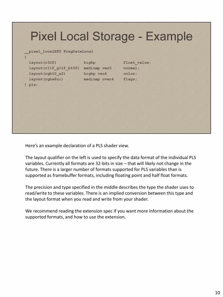
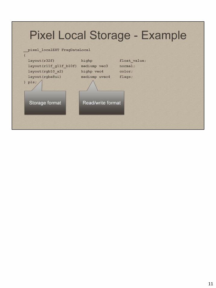
Here’s an example declaration of a PLS shader view. The layout qualifier on the left is used to specify the data format of the individual PLS variables. Currently all formats are 32-bits in size – that will likely not change in the future. There is a larger number of formats supported for PLS variables than is supported as framebuffer formats, including floating point and half float formats. The precision and type specified in the middle describes the type the shader uses to read/write to these variables. There is an implied conversion between this type and the layout format when you read and write from your shader. We recommend reading the extension spec if you want more information about the supported formats, and how to use the extension.
10
11
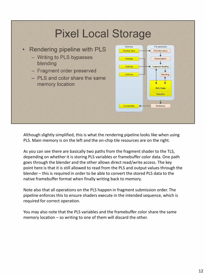
Although slightly simplified, this is what the rendering pipeline looks like when using PLS. Main memory is on the left and the on-chip tile resources are on the right. As you can see there are basically two paths from the fragment shader to the TLS, depending on whether it is storing PLS variables or framebuffer color data. One path goes through the blender and the other allows direct read/write access. The key point here is that it is still allowed to read from the PLS and output values through the blender – this is required in order to be able to convert the stored PLS data to the native framebuffer format when finally writing back to memory. Note also that all operations on the PLS happen in fragment submission order. The pipeline enforces this to ensure shaders execute in the intended sequence, which is required for correct operation. You may also note that the PLS variables and the framebuffer color share the same memory location – so writing to one of them will discard the other.
12

FBF is close to the existing API and so may be the smallest delta for existing deferred renderers. However it lacks the flexibility and additional storage formats of PLS as the storage format is defined and fixed for the render pass by the render target configuration. This is not an issue for deferred renderers, but does limit other applications. The fixed storage format can also be a better fit some hardware. FBF supports MSAA framebuffer formats, but does so by forcing per-sample shading. This is required for correct operation but the cost of shading per-sample can be prohibitive. Whether this is the best route in the future is something we are actively debating and investigating. The best known concern with FBF is the requirement to correctly place calls to glInvalidateFramebuffer. Making a mistake will not affect rendering behaviour and so is very difficult to detect in practice. The explicit load/store actions demonstrated in Metal and PLS offer a more robust and semantically clear alternative. Pete Harris wrote a blog post describing how to correctly call glInvalidateFramebuffer here: http://community.arm.com/groups/arm-mali-graphics/blog/2014/04/28/mali-graphics-performance-2-how-to-correctly-handle-framebuffers
13

PLS is still a simple delta to support from an existing deferred rendering setup, but has clearer semantics and additional flexibility. We have found we can support multiple variants of deferred rendering with the same shaders and modest use of #defines in the shader code. It should also allow easier future extensions as PLS is independent of the framebuffer configuration and C API. The ability to change the per-pixel view the shader is unique to PLS, but can imply require additional overhead. If the GPU has hardware to convert to the PLS storage formats, and this hardware is not configured by or otherwise dependent upon the framebuffer configuration, then the additional flexibility of PLS would have negligible cost. However, some devices may need to perform software format conversions where hardware does not exist or cannot be used independently of the framebuffer configuration. If the use cases of PLS justify the hardware investment required this should not be a concern in the longer term. The more immediate limitations of the current PLS extension are the lack of MRT and MSAA support. MRT support (the ability to resolve to multiple framebuffers) is a comparatively simple addition and a likely future addition. As mentioned with FBF, support for MSAA is not so straightforward. There are several options and we will return to this discussion when we discuss future work.
14

We’ll now briefly review how deferred rendering can be achieved through these extensions.
15
Last year, we investigated a variety of renderers using an early version of the PLS extension. In this we saw significant bandwidth – and therefore energy savings – by performing deferred rendering “on-chip”. A possible limitation of deferred is that your material description must be decoupled from the lighting evaluation by storing parameters in so called “g-buffers”. There are alternatives where the materials and lights are computed in a single shader. While these alternatives have been shown to be feasible in some settings they can be limited by the resulting shader complexity if the number of light types and shadowing options supported is large, and some (forward+ and lightstack) require depth to be rendered in a first pass. This requires two submissions of the scene geometry which naively requires twice the vertex processing and geometry bandwidth which is a considerable overhead, particularly on a tile-based renderer. As a result, although these options are clearly usable and have shipped in games, they are not as practical across such a wide spectrum as deferred today, although further innovation could improve this situation. For our purposes today we will focus on deferred rendering. Deferred rendering also maps to all extensions and APIs we have discussed.
16

The original Transporter demo was made in a pre-alpha build of Unity 5 using Enlighten. We have reconstructed the scene from the source artwork in a custom deferred renderer. The original demo used a simplified physically-based shader based on Brian Karis’ presentation in the Physically-Based Shading SIGGRAPH 2013 course (http://bit.ly/1kDCPsE) . It uses indirect lightmaps and cubemaps from Enlighten with the same GGX-based material response. The direct lighting is more basic as this is where computing the response would become excessive on mobile platforms for large numbers of lights. (Fewer higher quality lights would likely be feasible though.) The original demo was a single-pass forward renderer that supported a maximum of 2 dynamic lights per object and dynamic emissive surfaces. Other direct light sources were baked into lightmaps. In our reconstructed version we keep the same geometry, materials and Enlighten setup but render all lights dynamically using the light geometry and well-known stencil-culling trick. Using PLS we can support a HDR linear pipeline with the RGB10a2 storage format, or fp16 if we also use the ARM depth readback extension (which allows us to avoid storing depth). As well as testing a lighting configuration similar to the original demo with around 70 lights, we also benchmark using procedurally generated lights as has become customary for deferred rendering demonstrations . The demos are different enough that it does not make sense to compare them directly, but both implementations run on the same device (a Samsung Note 10.1 2014 edition, with ARM Mali-T628MP6 GPU) at real-time framerates. Reporting absolute performance figures are also rather uninformative as the scene/lights/camera can be arbitrary adapted to suit! But as a rule of thumb, tens of lights are certainly feasible with this level of scene and material complexity on the GPU in question. We see significant bandwidth reductions (see last years talk for figures) and performance increases on this more “real world” content when comparing to traditional deferred rendering - indications of around 10-25% uplift overall. This figure should be treated with some caution though as hardware has not yet been tuned to content created with these use cases in mind and these extensions are still relatively new.
17
We can now look at how approximate OIT can also be restructured to use TLS, and several possible implementations of it based on pixel local storage.
18
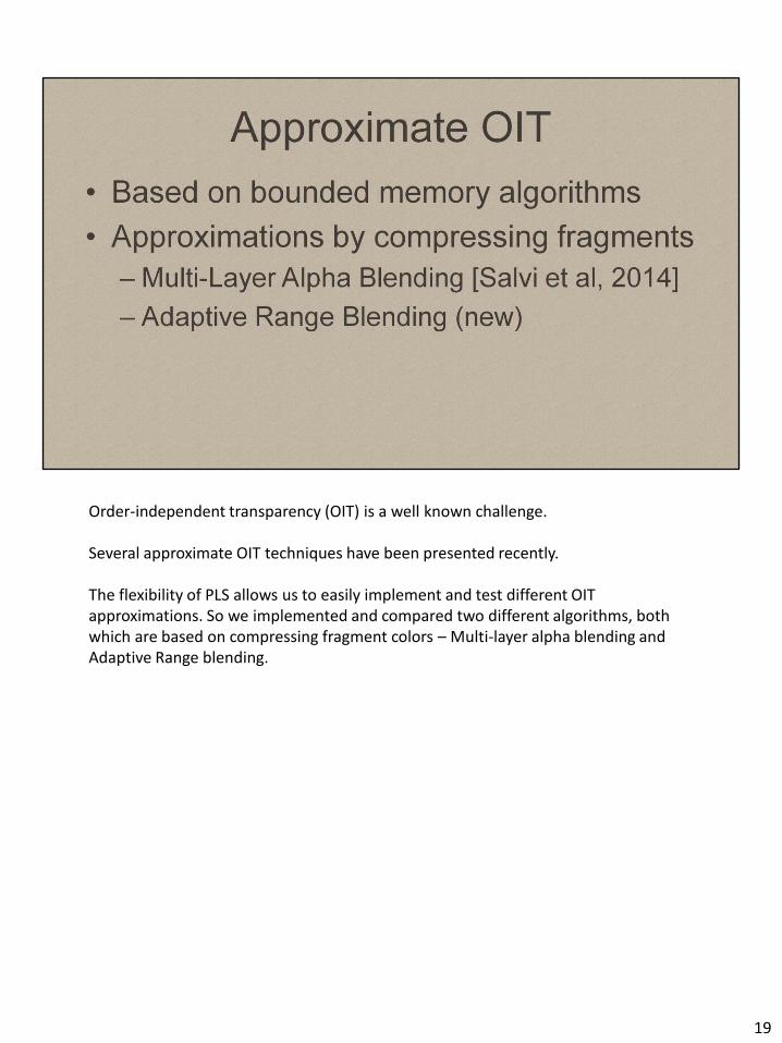
Order-independent transparency (OIT) is a well known challenge. Several approximate OIT techniques have been presented recently. The flexibility of PLS allows us to easily implement and test different OIT approximations. So we implemented and compared two different algorithms, both which are based on compressing fragment colors – Multi-layer alpha blending and Adaptive Range blending.
19
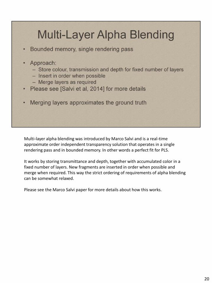
Multi-layer alpha blending was introduced by Marco Salvi and is a real-time approximate order independent transparency solution that operates in a single rendering pass and in bounded memory. In other words a perfect fit for PLS. It works by storing transmittance and depth, together with accumulated color in a fixed number of layers. New fragments are inserted in order when possible and merge when required. This way the strict ordering of requirements of alpha blending can be somewhat relaxed. Please see the Marco Salvi paper for more details about how this works.
20
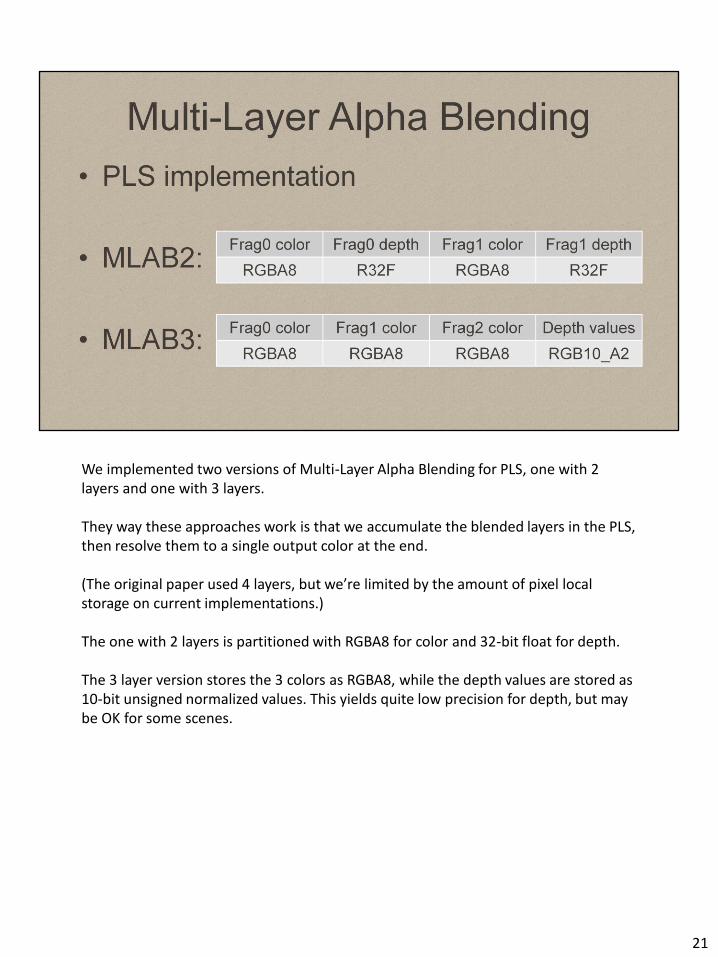
We implemented two versions of Multi-Layer Alpha Blending for PLS, one with 2 layers and one with 3 layers. They way these approaches work is that we accumulate the blended layers in the PLS, then resolve them to a single output color at the end. (The original paper used 4 layers, but we’re limited by the amount of pixel local storage on current implementations.) The one with 2 layers is partitioned with RGBA8 for color and 32-bit float for depth. The 3 layer version stores the 3 colors as RGBA8, while the depth values are stored as 10-bit unsigned normalized values. This yields quite low precision for depth, but may be OK for some scenes.
21

Another OIT algorithm we implemented was based on keeping track of the min/max depth of the incoming fragments. The main motivation behind the idea was to allocate more PLS space for color fragments and leave a fixed portion for keeping track of min/max depth range. This works well in comparison to multi-layer alpha blending when we have a small amount of storage space for fragments, but since it only keeps track of the depth range it doesn’t scale as well as MLAB – especially when the fragments are far apart and highly out of order.
22

For each incoming fragment the adaptive range algorithm compares the fragment depth value to the current pixel depth range. If the fragment is in front of the range, the existing stack of fragments are pushed towards the end and the new fragment is inserted at the front. The fragment that exits the stack is blended with the last fragment. If the fragment is inside the range, it is blended with an existing fragment color depending on its position inside the range. If the fragment is behind the range it is simply blended with the last fragment on the stack. Depending on where the fragment hits the range, it is either used as destination or source of the blend function.
23

For adaptive range the PLS is partitioned with a stack of 3 RGBA8 color values and 2 FP16 values for keeping track of the depth range.
24
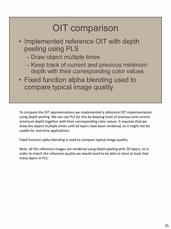
To compare the OIT approximations we implemented a reference OIT implementation using depth peeling. We can use PLS for this by keeping track of previous and current minimum depth together with their corresponding color values. It requires that we draw the object multiple times until all layers have been rendered, so it might not be usable for real-time applications. Fixed function alpha blending is used to compare typical image quality. Note: all the reference images are rendered using depth peeling with 20 layers, so in order to match the reference quality we would need to be able to store at least that many layers in PLS.
25

Here’s our reference frame. Note that we’re not using the typical particle cloud test-scene here. Our test scene will make errors more apparent.
26
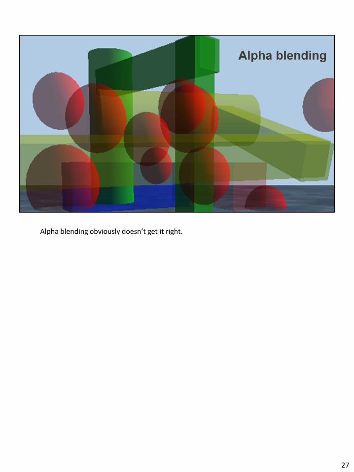
Alpha blending obviously doesn’t get it right.
27

Even 2 layers is much better, but we observe an obvious artifact on the lower left sphere.
28
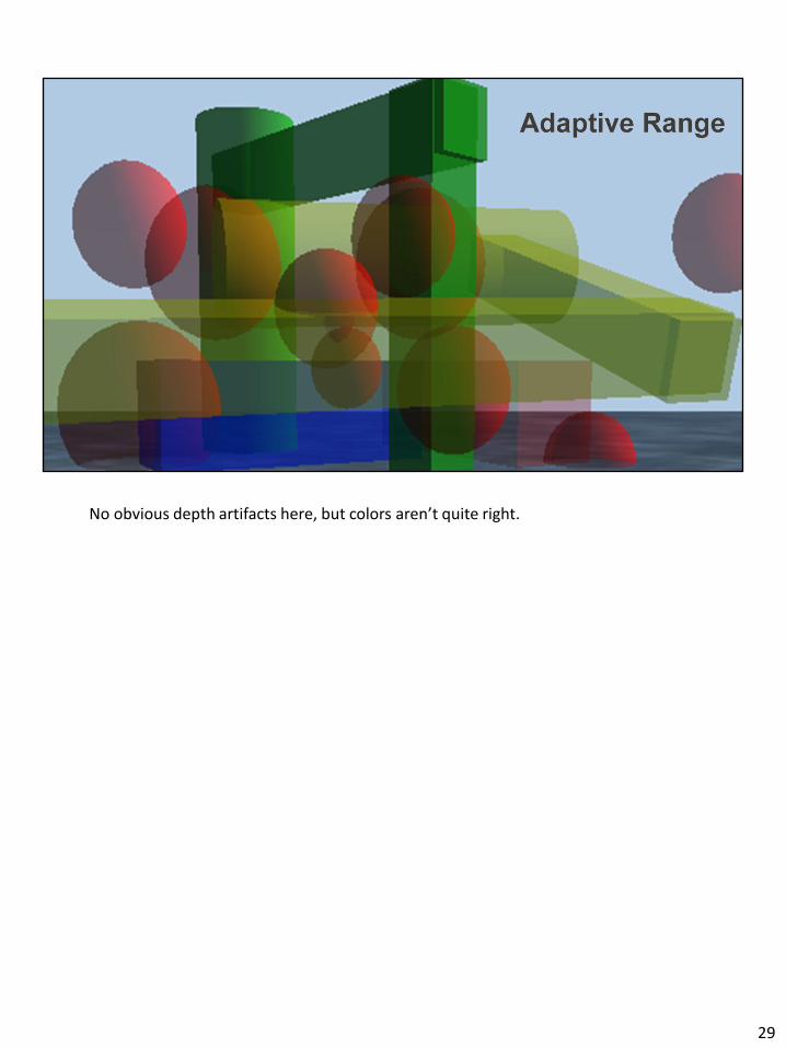
No obvious depth artifacts here, but colors aren’t quite right.
29

3 layers gets us closer, but some depth artifacts on the middle sphere
30

31
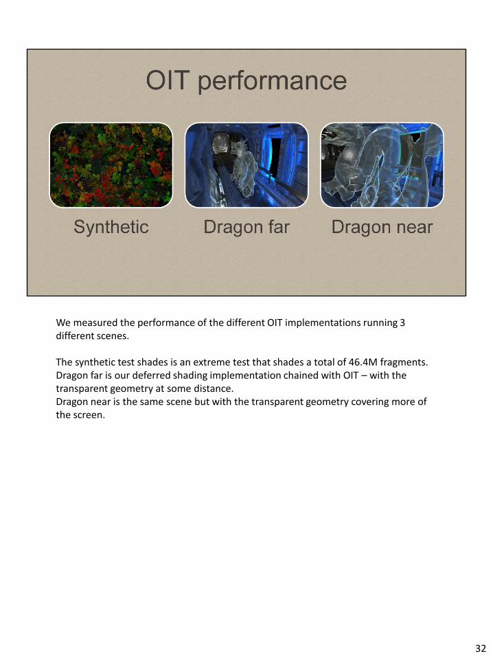
We measured the performance of the different OIT implementations running 3 different scenes. The synthetic test shades is an extreme test that shades a total of 46.4M fragments. Dragon far is our deferred shading implementation chained with OIT – with the transparent geometry at some distance. Dragon near is the same scene but with the transparent geometry covering more of the screen.
32

Performance comparison between the different implementations running different content. The performance numbers have been normalized in comparison to alpha blended rendering. These results are from a Note 10.1 device running a Mali-T628MP6 GPU. As you can see the MLAB algorithms scale down in performance when increasing the number of layers – this is expected. The adaptive range algorithm achieves the highest performance, while quality-wise it’s somewhere between MLAB2 and MLAB3.
33
34

PLS allows us to chain techniques together. This makes combining techniques such as deferred shading and order-independent transparency very easy. In the above schematics we have a regular deferred shading opaque phase which fills up the PLS G-buffer, accumulate lights and resolve. After this is done we render all transparent geometry using OIT. For this we repartition the layout of the PLS according to the different OIT algorithm we tested. This is what makes PLS unique - the ability to chain complex techniques together without hitting external memory. We achieve this by repartitioning the TLS. All processing – up to the final color resolve - is completely independent of the output framebuffer format.
35

Deferred Shading with reference OIT
36
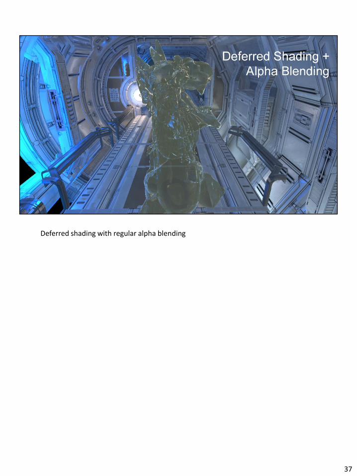
Deferred shading with regular alpha blending
37
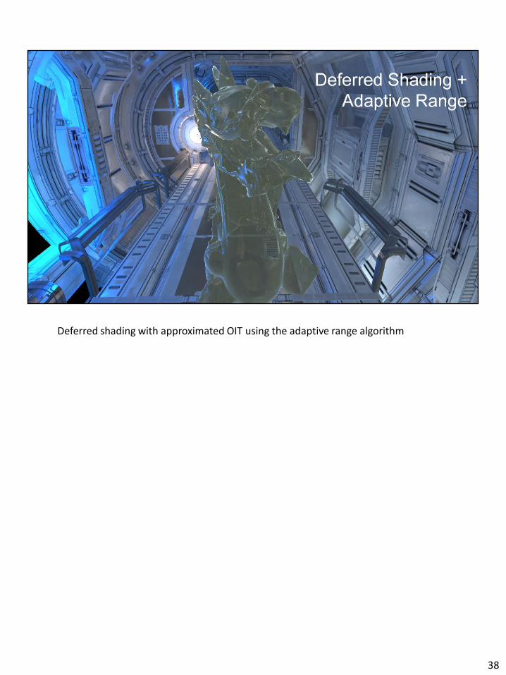
Deferred shading with approximated OIT using the adaptive range algorithm
38

Deferred shading with Multi-Layer alpha blending This gives visually good results – fairly close to the reference. Note that with TLS this and the preceding adaptive range example can both be rendered in a single pass.
39

Deferred Shading with reference OIT
40
41
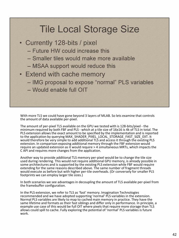
With more TLS we could have gone beyond 3 layers of MLAB. So lets examine that controls the amount of data available per-pixel. The amount of per-pixel TLS available on the GPU we tested with is 128-bits/pixel - the minimum required by both FBF and PLS - which at a tile size of 16x16 is 4k of TLS in total. The PLS extension allows the exact amount to be specified by the implementation and is reported to the application by querying MAX_SHADER_PIXEL_LOCAL_STORAGE_FAST_SIZE_EXT. It would therefore be very simple to add additional TLS and access it through the existing PLS extension. In comparison exposing additional memory through the FBF extension would require an updated extension as it would require > 4 simultaneous MRTs, which impacts the C API and requires more changes from the application. Another way to provide additional TLS memory per-pixel would be to change the tile size used during rendering. This would not require additional GPU memory, is already possible in some architectures and is supported by the existing PLS extension while FBF would require extending for the same reasons described above. The same number of fragment threads would execute as before but with higher per-tile overheads. (Or conversely for smaller PLS footprints we can employ larger tile sizes.) In both scenarios we see advantages in decoupling the amount of TLS available per-pixel from the framebuffer configuration. In the PLS extension, we refer to TLS as ‘fast’ memory. Imagination Technologies recommended and we have adopted supporting ‘normal’ PLS variables in the extension. Normal PLS variables are likely to map to cached main memory in practice. They have the same lifetime and formats as their fast siblings and differ only in performance. In principle, a example use case of this would be full OIT where pixels that require more storage than TLS allows could spill to cache. Fully exploring the potential of ‘normal’ PLS variables is future work.
42
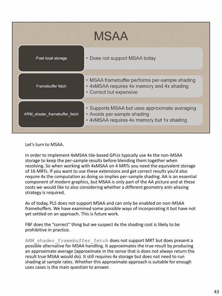
Let’s turn to MSAA. In order to implement 4xMSAA tile-based GPUs typically use 4x the non-MSAA storage to keep the per-sample results before blending them together when resolving. So when working with 4xMSAA on 4 MRTs you need the equivalent storage of 16 MRTs. If you want to use these extensions and get correct results you’d also require 4x the computation as doing so implies per-sample shading. AA is an essential component of modern graphics, but MSAA is only part of the AA picture and at these costs we would like to also considering whether a different geometry anti-aliasing strategy is required. As of today, PLS does not support MSAA and can only be enabled on non-MSAA framebuffers. We have examined some possible ways of incorporating it but have not yet settled on an approach. This is future work. FBF does the “correct” thing but we suspect 4x the shading cost is likely to be prohibitive in practice. ARM_shader_framebuffer_fetch does not support MRT but does present a possible alternative for MSAA handling. It approximates the true result by producing an approximate average (approximate in the sense that is does not always return the result true MSAA would do). It still requires 4x storage but does not need to run shading at sample rates. Whether this approximate approach is suitable for enough uses cases is the main question to answer.
43

We would like to ask, “do we really need MSAA?” Graphics certainly does need AA, but 4xMSAA only has a modest impact. In particular, it has no impact on aliasing related to shader output - something which is especially visible in physically-based shading where smaller highlights are more common. It is also likely to be unaffordable at higher rates. Techniques such as FXAA have shown that it’s quite possible to address some aliasing problem entirely in image space (contrary to everything you may have learned from signal processing lessons!). But these techniques also require large amounts of memory bandwidth especially at higher resolutions. An advantage of the existing MSAA implementation on Mali GPUs is that it doesn’t incur any extra memory bandwidth. One option could be to ignore MSAA altogether when using PLS. This would allow PLS to be compatible with MSAA buffers but all shading would occur per-fragment. We could also allow per-sample shading, but with the costs outlined earlier. We could allow applications to specify MSAA per PLS variable using additional qualifiers. This would allow much finer grained control. Particularly for PLS where the view can be changed per-shader and not everything you are likely to store in TLS would want MSAA (e.g. an array of indices such as we employed in the lightstack renderer). This appears to be a better fit for PLS but it does introduce a considerable amount of extra complexity. Supporting more than one of these options is also a possibility.
44
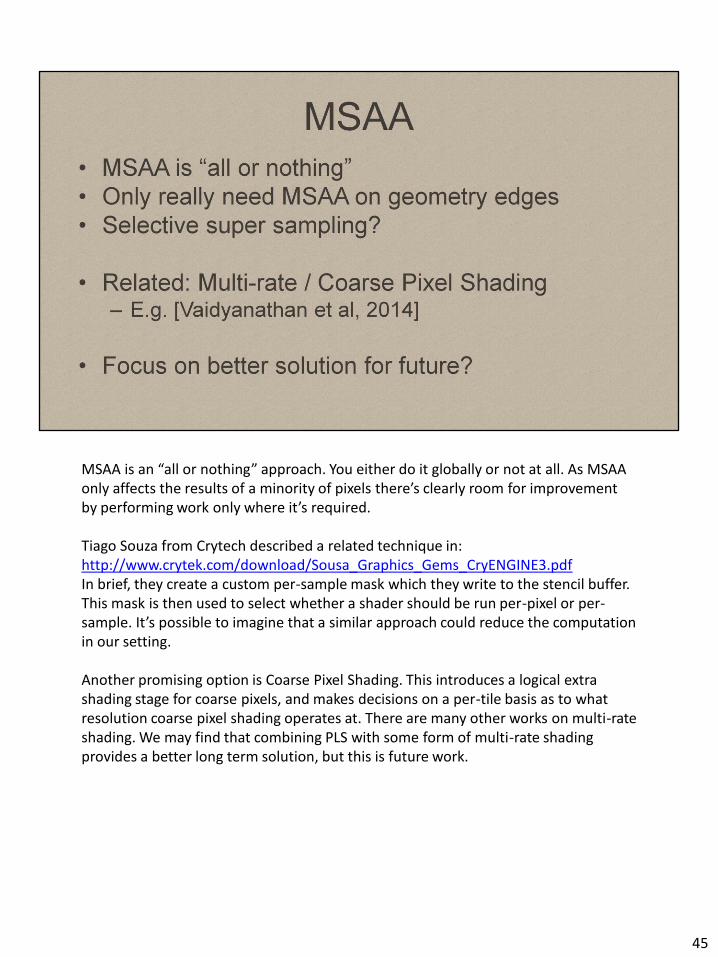
MSAA is an “all or nothing” approach. You either do it globally or not at all. As MSAA only affects the results of a minority of pixels there’s clearly room for improvement by performing work only where it’s required. Tiago Souza from Crytech described a related technique in: http://www.crytek.com/download/Sousa_Graphics_Gems_CryENGINE3.pdf In brief, they create a custom per-sample mask which they write to the stencil buffer. This mask is then used to select whether a shader should be run per-pixel or per-sample. It’s possible to imagine that a similar approach could reduce the computation in our setting. Another promising option is Coarse Pixel Shading. This introduces a logical extra shading stage for coarse pixels, and makes decisions on a per-tile basis as to what resolution coarse pixel shading operates at. There are many other works on multi-rate shading. We may find that combining PLS with some form of multi-rate shading provides a better long term solution, but this is future work.
45

In summary, we have seen how existing technology and extensions can be used to implement deferred shading, approximate OIT, as well as combining them into a single pass in a very bandwidth efficient manner. In the future: - We would like to explore the convergence of PLS/MSAA/Coarse. The idea being that work can be done at a variable rate. - We’d obviously like to see these technologies be widely adopted, whether that’s in the current form or a different variation. - All TLS-related extensions assume a well defined framebuffer lifetime. In Metal this is explicit but in the current OpenGL/ES standards this is implicit. We would very much like to see explicit lifetimes in graphics APIs. - A generalization of the PLS ideas to GPU compute, by which we mean “fragment shader compute”, in contrast to say, OpenCL with local memory. We’d want compute shaders create the input data for the compute state using the rasterizer.
46
Thanks! If you have any questions or feedback please do get in contact.
47
48

49
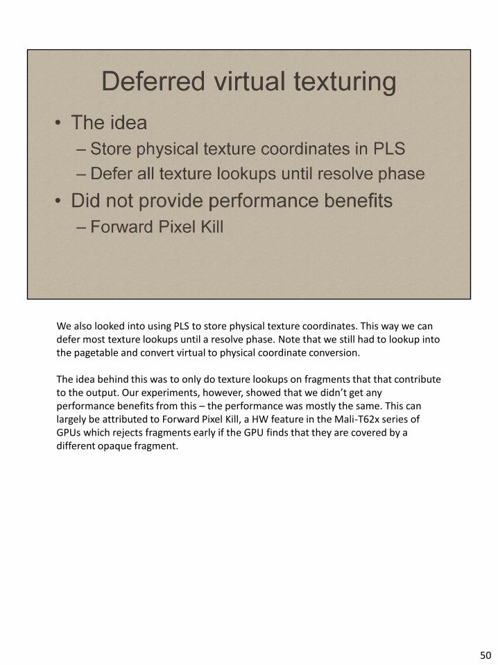
We also looked into using PLS to store physical texture coordinates. This way we can defer most texture lookups until a resolve phase. Note that we still had to lookup into the pagetable and convert virtual to physical coordinate conversion. The idea behind this was to only do texture lookups on fragments that that contribute to the output. Our experiments, however, showed that we didn’t get any performance benefits from this – the performance was mostly the same. This can largely be attributed to Forward Pixel Kill, a HW feature in the Mali-T62x series of GPUs which rejects fragments early if the GPU finds that they are covered by a different opaque fragment.
50