s.no practical name date remark - edutechlearners - · pdf file · 2015-03-23s.no...
TRANSCRIPT
S.No Practical Name Date Remark
1. To study motherboard.
2. Study of microprocessor.
3. To study SMPS and UPS.
4. To study the CD-ROM and DVD-ROM.
5. To study working of keyboard and mouse.
6. To study different ports and slots.
7. To study various types of Cables & Connectors.
8. Study of monitor.
9. To study different types of printers.
10. To assemble a PC.
11. To study Floppy Disk Drive.
Practical-1
Aim:-To study motherboard.
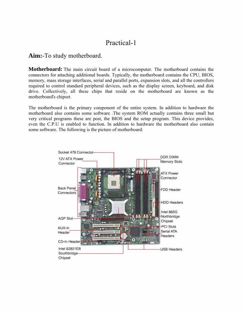
Motherboard: The main circuit board of a microcomputer. The motherboard contains the connectors for attaching additional boards. Typically, the motherboard contains the CPU, BIOS, memory, mass storage interfaces, serial and parallel ports, expansion slots, and all the controllers required to control standard peripheral devices, such as the display screen, keyboard, and disk drive. Collectively, all these chips that reside on the motherboard are known as the motherboard's chipset.
The motherboard is the primary component of the entire system. In addition to hardware the motherboard also contains some software .The system ROM actually contains three small but very critical programs these are post, the BIOS and the setup program. This device provides, even the C.P.U is enabled to function. In addition to hardware the motherboard also contain some software. The following is the picture of motherboard:

1. Mouse & keyboard: Keyboard Connectors are two types basically. All PCs have a Key board port connected directly to the motherboard. The oldest, but still quite common type, is a special DIN, and most PCs until recently retained this style connector. The AT-style keyboard connector is quickly disappearing, being replaced by the smaller mini DIN PS/2-style keyboard connector. You can use an AT-style keyboard with a PS/2-style socket (or the other way around) by using a converter. Although the AT connector is unique in PCs, the PS/2-style mini-DIN is also used in more modern PCs for the mouse. Fortunately, most PCs that use the mini-DIN for both the keyboard and mouse clearly mark each mini-DIN socket as to its correct use. Some keyboards have a USB connection, but these are fairly rare compared to the PS/2 connection keyboards. 2. USB (Universal serial bus): USB is the General-purpose connection for PC. You can find USB versions of many different devices, such as mice, keyboards, scanners, cameras, and even printers. A USB connector's distinctive rectangular shape makes it easily recognizable. USB has a number of features that makes it particularly popular on PCs. First, USB devices are hot swappable. You can insert or remove them without restarting your system.
3. Parallel port: Most printers use a special connector called a parallel port. Parallel port carries data on more than one wire, as opposed to the serial port, which uses only one wire. Parallel ports use a 25-pin female DB connector. Parallel ports are directly supported by the motherboard through a direct connection or through a dangle.
4. CPU Chip: The central processing unit, also called the microprocessor performs all the calculations that take place inside a pc. CPUs come in Variety of shapes and sizes. Modern CPUs generate a lot of heat and thus require a cooling fan or heat sink. The cooling device (such as a cooling fan) is removable, although some CPU manufactures sell the CPU with a fan permanently attached.
5. RAM slots: Random-Access Memory (RAM) stores programs and data currently being used by the CPU. RAM is measured in units called bytes. RAM has been packaged in many different ways. The most current package is called a 168-pin DIMM (Dual Inline Memory module).
6. Floppy controller: The floppy drive connects to the computer via a 34-pin ribbon cable, which in turn connects to the motherboard. A floppy controller is one that is used to control the floppy drive.
7. IDE controller: Industry standards define two common types of hard drives: EIDE and SCSI. Majority of the PCs use EIDE drives. SCSI drives show up in high end PCs such as network servers or graphical workstations. The EIDE drive connects to the hard drive via a 2-inch-wide, 40-pin ribbon cable, which in turn connects to the motherboard. IDE controller is responsible for controlling the hard drive.

8. PCI slot: Intel introduced the Peripheral component interconnect bus protocol. The PCI bus is used to connect I/O devices (such as NIC or RAID controllers) to the main logic of the computer. PCI bus has replaced the ISA bus.
9. ISA slot: (Industry Standard Architecture) It is the standard architecture of the Expansion bus. Motherboard may contain some slots to connect ISA compatible cards. The memory address bus is to 32 bits .The bus speed is 8.33 MHZ and the bandwidth is 16 bits.
10. CMOS Battery: To provide CMOS with the power when the computer is turned off all motherboards comes with a battery. These batteries mount on the motherboard in one of three ways: the obsolete external battery, the most common onboard battery, and built-in battery. 11. AGP slot: If you have a modern motherboard, you will almost certainly notice a single connector that looks like a PCI slot, but is slightly shorter and usually brown. You also probably have a video card inserted into this slot. This is an Advanced Graphics Port (AGP) slot 12. CPU slot: To install the CPU, just slide it straight down into the slot. Special notches in the slot make it impossible to install them incorrectly. So remember if it does not go easily, it is probably not correct. Be sure to plug in the CPU fan's power.
13. Power supply plug in: The Power supply, as its name implies, provides the necessary electrical power to make the pc operate. The power supply takes standard 110-V AC power and converts into +/-12-Volt, +/-5-Volt, and 3.3-Volt DC power.
The power supply connector has 20-pins, and the connector can go in only one direction.

Aim:-S
A micropsingle multipurpinstructiodigital lorepresent
The advGeneral-pmultimedof embedautomobi
Structu
The interintended physical package interconnAdvancin
Study of m
processor inintegrated
pose, prograons stored inogic, as it hted in the bin
vent of low-purpose micdia display, dded systemiles to cellul
ure:-
rnal arrangempurposes olimitations terminations
nections it ing technolog
micropro
ncorporates (IC), or
ammable devn its memoryhas internalnary numera
-cost compucroprocessorand commu
ms, providinlar phones an
ment of a mof the proceof the numbs that can cos possible tgy makes mo
Pra
ocessor.
the functionat most
vice that accy, and provil memory. Mal system.
uters on intrs in personaunication oveng digital cond industrial
microprocessoessor. The cber of transionnect the pto make on ore complex
actical-2
ns of a compa few
cepts digital ides results Microproces
tegrated ciral computerser the Internontrol of a l process con
or varies depcomplexity istors that c
processor to the chip, an
x and powerf
2
uter's centraw integra
data as inpuas output. It
ssors operat
rcuits has trs are used fo
net. Many mmyriad of
ntrol.
pending on tof an integan be put onother parts ond the heat ful chips feas
al processingated circuut, processet is an exame on numbe
ransformed for computat
more microprobjects fro
the age of thgrated circuinto one chipof the systemthat the ch
sible to man
g unit (CPU)uits. It is es it accordinmple of seque
ers and sym
modern soction, text edrocessors areom applianc
he design anit is boundep, the numbm, the numbhip can dissinufacture.
) on a a
ng to ential mbols
ciety. diting, e part es to
nd the ed by ber of ber of ipate.

A block diagram of the internal architecture of the Z80 microprocessor, showing the arithmetic and logic section, register file, control logic section, and buffers to external address and data lines
Intel 4004:-
The Intel 4004 is generally regarded as the first commercially available microprocessor,and cost $60. The project that produced the 4004 originated in 1969, when Busicom, a Japanese calculator manufacturer, asked Intel to build a chipset for high-performance desktop calculators. Busicom's original design called for a programmable chip set consisting of seven different chips. Three of the chips were to make a special-purpose CPU with its program stored in ROM and its data stored in shift register read-write memory.
Intel 4004, the first commercial microprocessor
Differences between processor:-
8 bit 12 bit 16 bit 32 bit 64 bit Image
Type Intel 8008 was
first 8 bit microprocessor
The Intersil 6100 family consisted of a 12-bit microprocessor
The first multi-chip 16-bit microprocessor was the National Semiconductor IMP-16
The most significant of the 32-bit designs is the MC68000
Intel 64 are 64 bit microprocessor
Bus 8 bit 12 bit 16 bit 32 bit 64 bit Example
Intel 8080, Zilog Z80
Harris HM-6100 TMS 9900,
iAPX 432, MC68010
EM64T

Multi-core processor:-
Multi Core processor
Definition A multi-core processor is simply a single chip containing more than one microprocessor core, effectively multiplying the potential performance with the number of cores
Image
Advantages Improve overall performance Because the cores are physically very close they interface at much faster clock rates
Example Pentium dual-core and quad-core processors
Practical-3
Aim:- To study SMPS and UPS.
SMPS
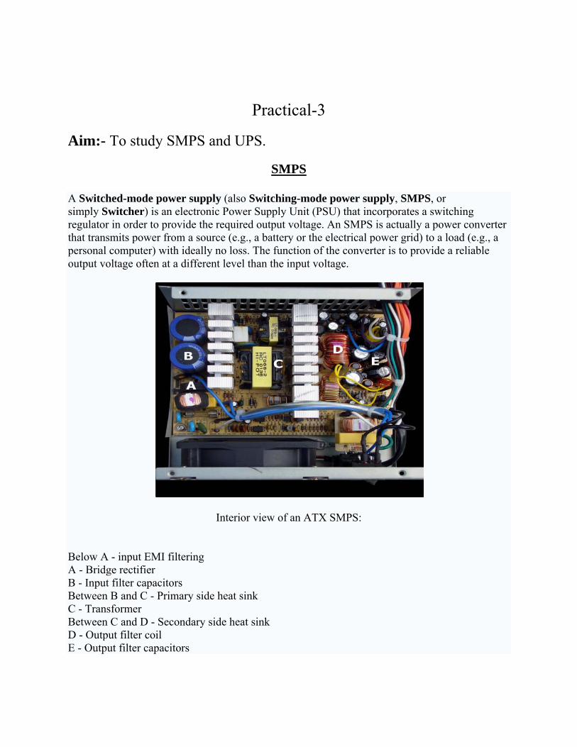
A Switched-mode power supply (also Switching-mode power supply, SMPS, or simply Switcher) is an electronic Power Supply Unit (PSU) that incorporates a switching regulator in order to provide the required output voltage. An SMPS is actually a power converter that transmits power from a source (e.g., a battery or the electrical power grid) to a load (e.g., a personal computer) with ideally no loss. The function of the converter is to provide a reliable output voltage often at a different level than the input voltage.
Interior view of an ATX SMPS:
Below A - input EMI filtering A - Bridge rectifier B - Input filter capacitors Between B and C - Primary side heat sink C - Transformer Between C and D - Secondary side heat sink D - Output filter coil E - Output filter capacitors

The coil and large yellow capacitor below E are additional input filtering components that are mounted directly on the power input connector and are not part of the main circuit board.
Classification
SMPS can be classified into four types according to the input and output waveforms:
AC in, DC out: rectifier, off-line converter input stage DC in, DC out: voltage converter, or current converter, or DC to DC converter AC in, AC out: frequency changer, cycloconverter, transformer DC in, AC out: inverter
Applications:
Switched-mode PSUs in domestic products such as personal computers often have universal inputs, meaning that they can accept power from most mains supplies throughout the world, with rated frequencies from 50 Hz to 60 Hz and voltages from 100 V to 240 V (although a manual voltage range switch may be required). In practice they will operate from a much wider frequency range and often from a DC supply as well. In 2006, at an Intel Developers Forum, Google engineers proposed the use of a single 12 V supply inside PCs, due to the high efficiency of switch mode supplies directly on the PCB.
Switched mode mobile phone charger
SMPS Connectors:
Amphenol connector gives power supply to Mother Board

Mole x gives power supply to IDE drives Mini Molex gives power supply to floppy drive.
UPS
An uninterruptible power supply, also uninterruptible power source, UPS or battery backup, is an electrical apparatus that provides emergency power to a load when the input power source, typically the utility mains, fails. A UPS differs from an auxiliary or emergency power system or standby generator in that it will provide instantaneous or near-instantaneous protection from input power interruptions by means of one or more attached batteries and associated electronic circuitry for low power users, and or by means of diesel generators and flywheels for high power users. The on-battery runtime of most uninterruptible power sources is relatively short—5–15 minutes being typical for smaller units—but sufficient to allow time to bring an auxiliary power source on line, or to properly shut down the protected equipment.
Technologies
The general categories of modern UPS systems are on-line, line-interactive or standby. An on-line UPS uses a "double conversion" method of accepting AC input, rectifying to DC for passing through the battery (or battery strings), then inverting back to 120V/240V AC for powering the protected equipment. A line-interactive UPS maintains the inverter in line and redirects the battery's DC current path from the normal charging mode to supplying current when power is

lost. In a standby ("off-line") system the load is powered directly by the input power and the backup power circuitry is only invoked when the utility power fails. Most UPS below 1 kVA are of the line-interactive or standby variety which is usually less expensive.
For large power units, Dynamic Uninterruptible Power Supply are sometimes used. A synchronous motor/alternator is connected on the mains via a choke. Energy is stored in a flywheel. When the mains power fails, an Eddy-current regulation maintains the power on the load. DUPS are sometimes combined or integrated with a diesel-generator, forming a diesel rotary uninterruptible power supply, or DRUPS.
A Fuel cell UPS has been developed in recent years using hydrogen and a fuel cell as a power source, potentially providing long run times in a small space.
Applications
N+1
In large business environments where reliability is of great importance, a single huge UPS can also be a single point of failure that can disrupt many other systems. To provide greater reliability, multiple smaller UPS modules and batteries can be integrated together to provide redundant power protection equivalent to one very large UPS. "N+1" means that If the load can be supplied by N modules, the installation will contain N+1 modules. In this way, failure of one module will not impact system operation
Multipleredundancy
Many computer servers offer the option of redundant power supplies, so that in the event of one power supply failing, one or more other power supplies are able to power the load. This is a critical point - each power supply must be able to power the entire server by itself.
Redundancy is further enhanced by plugging each power supply into a different circuit (i.e. to a different circuit breaker).
Outdooruse
When a UPS system is placed outdoors, it should have some specific features that guarantee that it can tolerate weather with a 'minimal to none' effect on performance. Factors such as temperature, humidity, rain, and snow among others should be considered by the manufacturer when designing an outdoor UPS system. Operating temperature ranges for outdoor UPS systems could be around −40 °C to +55 °C.
Internalsystems
UPS systems can be designed to be placed inside a computer chassis. There are two types of Internal UPS. The first type is a miniaturized regular UPS that is made small enough to fit into a

5.25″ CD-ROM slot bay of a regular computer chassis. The other type are re-engineered switching power supplies that utilize dual power sources of AC and/or DC as power inputs and have an AC/DC built-in switching management control units.

Practical- 4
Aim:- To study the CD-ROM and DVD-ROM.
CD-ROM
The Compact Disk - Read Only Memory (CD-ROM) drive has gone from pricey luxury to inexpensive necessity on the modern PC. The CD-ROM has opened up new computing vistas that were never possible before, due to its high capacity and broad applicability. In many ways, the CD-ROM has replaced the floppy disk drive, but in many ways it has allowed us to use our computers in ways that we never used them before. In fact, the "multimedia revolution" was largely a result of the availability of cheap CD-ROM drives.
A CD can store up to 74 minutes of music, so the total amount of digital data that must be stored on a CD is:
44,100 samples/channel/second x 2 bytes/sample x 2 channels x 74 minutes x 60 seconds/minute = 783,216,000 bytes
To fit more than 783 megabytes (MB) onto a disc only 4.8 inches (12 cm) in diameter requires that the individual bytes be very small.
CD Drive Components:-
The CD drive has the job of finding and reading the data stored as bumps on the CD. Considering how small the bumps are, the CD drive is an exceptionally precise piece of equipment. The drive consists of three fundamental components:
· A drive motor spins the disc. This drive motor is precisely controlled to rotate between 200 and 500 rpm depending on which track is being read.
· A laser and a lens system focus in on and read the bumps.

· A tracking mechanism moves the laser assembly so that the laser's beam can follow the spiral track. The tracking system has to be able to move the laser at micron resolutions.
CD Drive- Basic design:-
A schematic of an optical three-beam pick-up of a CD drive is shown in the next figure along with the laser beam route through the system.
Cross-section of a CD
A CD has a single spiral track of data, circling from the inside of the disc to the outside. The fact thatthe spiral track starts at the center means that the CD can be smaller than 4.8 inches (12 cm) if desired, and in fact there are now plastic baseball cards and business cards that you can put in a CD player. CD business cards hold about 2 MB of data before the size and shape of the card cuts off the spiral.
Here's how the CD-ROM works:
1. A beam of light energy is emitted from an infrared laser diode and aimed toward a reflecting mirror. The mirror is part of the head assembly, which moves linearly along the surface of the disk.

2. The light reflects off the mirror and through a focusing lens, and shines onto a specific point on the disk.
3. A certain amount of light is reflected back from the disk. The amount of light reflected depends on which part of the disk the beam strikes: each position on the disk is encoded as a one or a zero based on the presence or absence of "pits" in the surface of the disk. This is discussed in more detail in the section on CD-ROM media.
4. A series of collectors, mirrors and lenses accumulates and focuses the reflected light from the surface of the disk and sends it toward a photo detector.
5. The photo detector transforms the light energy into electrical energy. The strength of the signal is dependent on how much light was reflected from the disk.
DVD-ROM
A Digital Versatile Disc - Read Only Memory, or DVD-ROM, is a media storage disk that closely resembles a CD or compact disc. The major difference is that the DVD is formatted to hold far more data. A CD commonly has a capacity of 650 megabytes, while the smallest capacity DVD can store about seven times more data, or 4.38 gigabytes (GB). There are various kinds of DVDs, but the DVD-ROM refers to a read-only disc, or a disc that cannot be written over. A DVD movie bought from the local video store is a good example. Blank DVDs with designations like "DVD-R" and "DVD+R" are formatted, recordable DVDs. The —R and +R refer to competing format standards, but both will record movies, audio, or other data.
How does a DVD work?
A DVD works exactly the same way, but it can hold a lot more information -- about 4.7 gigabytes (about seven times as much as a CD). DVDs can hold more data than CDs because the bumps are smaller and the tracks are closer together, giving DVDs more storage space. Here are the typical contents of a movie stored on a DVD:
· Up to 133 minutes of high-resolution video in letterbox or pan-and-scan format, at 720 dots of horizontal resolution (The video compression ratio is typically 40:1 under MPEG-2.)
· Soundtrack presented in up to eight languages using 5.1 channel Dolby digital surround sound
· Subtitles in up to 32 languages

Storing Data on a DVD
DVDs are of the same diameter and thickness as CDs, and they are made using some of the same materials and manufacturing methods. Like a CD, the data on a DVD is encoded in the form of small pits and bumps in the track of the disc.
A DVD is composed of several layers of plastic, totaling about 1.2 millimeters thick. Each layer is created by injection molding polycarbonate plastic. This process forms a disc that has microscopic bumps arranged as a single, continuous and extremely long spiral track of data. More on the bumps later.
Once the clear pieces of polycarbonate are formed, a thin reflective layer is sputtered onto the disc, covering the bumps. Aluminum is used behind the inner layers, but a semi-reflective gold layer is used for the outer layers, allowing the laser to focus through the outer and onto the inner layers. After all of the layers are made, each one is coated with lacquer, squeezed together and cured under infrared light. For single-sided discs, the label is silk-screened onto the non readable side. Double-sided discs are printed only on the non readable area near the hole in the middle. Cross sections of the various types of completed DVDs (not to scale) look like this:
Each writable layer of a DVD has a spiral track of data. On single-layer DVDs, the track always circles from the inside of the disc to the outside. That the spiral track starts at the center means that a single-layer DVD can be smaller than 12 centimeters if desired.
What the image to the right cannot impress upon you is how incredibly tiny the data track is -- just 740 nanometers separate one track from the next (a nanometer is a billionth of a meter). And the elongated bumps that make up the track are each 320 nanometers wide, a minimum of 400 nanometers long and 120 nanometers high. The following figure illustrates looking through the polycarbonate layer at the bumps.

Practical-5
Aim: To study working of keyboard and mouse.
The computer keyboard is the peripheral used to enter data (text and characters) into the computer, manage applications or enter command to be executed. The different types of keyboards contain generally from 83 to 105 keys placed sometimes differently. Most of these keys are known as alphanumeric keys with letters and numbers, others permit to input punctuation.
There are also many special keys used for different functions such as to delete or enter data or command, print screen, escape, etc
Working of keyboard:
1. Keystroke Detection:
The keyswitches are the devices that are used to actually detect "keystrokes", that is, the finger motions that mean a key has been pressed. The keyswitches respond to mechanical motion by creating an electrical signal that tells the keyboard's internal controller that "a key was pressed".

From there, the internal circuitry must take over and determine which key, and figure out how to communicate this fact to the system.
2. Scan code detection:
A scancode (or scan code) is the data that most computer keyboards send to a computer to report which keys have been pressed. A number, or sequence of numbers, is assigned to each key on the keyboard. The first issue that the circuitry must deal with is figuring out which key was actually pressed. This would seem fairly simple: there's one keyswitch for each key, and that keyswitch could be connected to the keyboard controller; it would just send it a signal when that key was pressed.
The keyswitch sensors are arranged in a matrix of rows and columns, not unlike a spreadsheet. When a specific key is pressed, it generates a signal for the row and column assigned to that key. The controller is programmed to know that, for example, the letter "T" is at row # 3 and column #8, and so on, for each key. This design means that instead of, say, 104 signal lines being needed for a 104-key keyboard, 9 row lines and about 12 column lines will suffice, for example. (The number of rows and columns doesn't necessarily correspond to the number of rows and columns of keys on the keyboard, since the wiring of different keys can be changed by the design of the circuit board in the keyboard.)
3. Make and Break Codes
The keyboard scan codes are broken into 'Make' and 'Break' codes. One make code is sent every time a key is pressed. Once released, a break code is sent. For most keys, the break code is a data stream of F0 followed by the scan code for the key. Using this configuration, the system can tell whether or not the key has been pressed, and if more than one key is being held down, it can distinguish which key has been released. Using two codes, the PC system can tell not only what keys were pressed, but for how long, and also which keys have been held down for a period of time. One example of this is when a shift key is held down. While it is held down, the '3' key should return the value for the '#' symbol instead of the value for the '3' symbol. Another thing to note is that if a key is held down, the make code is continuously sent via the typematic rate until it is released, when the break code is sent. The full set of make and break codes is included in the scan code sets available from USAR Systems.
Keyboard Operation
The scan codes are sent serially on the bi-directional data line. When neither the keyboard nor the computer wants to send data, the data line and the clock line are high (inactive). The transmission of a single key or command consists of the following components:
start bit ('0')
8 data bits representing the scan code

parity bit (odd parity such that the eight data bits plus the parity bit are an odd number of ones)
stop bit ('1')
A total of 11 bits
The following describes the sequence of events that occur during a transmission of a command by the keyboard.
1. The keyboard checks to ensure that both the clock and keyboard lines are inactive. If both are inactive, the keyboard prepares the 'start' bit by dropping the data line low.
2. The keyboard then drops the clock line low for approximately 35us.
3. The keyboard will then clock the remaining 10 bits at an approximate rate of 70us per clock period.
4. The computer is responsible for recognizing the ‘start’ bit and to receive the data. The data, which is 8 bits, is followed by a parity bit and finally a stop bit. If the keyboard wishes to send more data, it follows the 11th bit immediately with the next ‘start’ bit.
This pattern repeats until the keyboard is finished sending data at which point the clock and data lines will return to their inactive state. When implementing the VHD code, it will be necessary to filter the keyboard clock to ensure clean signals.
The computer system can also send commands to the keyboard. These include
keyboard initialization data
request for resend of the last
illumination of status lights including caps-lock, scroll-lock, and Num lock LED.
The computer system sends data to the keyboard as follows:
1. System drives the clock line low for approximately 60us (clock line is bi-directional).
2. System drives the data line low and then releases the clock line.
3. The keyboard will generate clock signals in order to clock in the command.
4. The system will send its 8 bit command followed by a parity bit and a stop bit.

5. After the stop bit is driven high, the data line is released.
6. Upon completion of the command, the keyboard will send an ACK signal if it received the data successfully.
Keyboard Connectors:
1. 6 pin DIN Connector
2.5 pin DIN Connector
3. USB pin connector
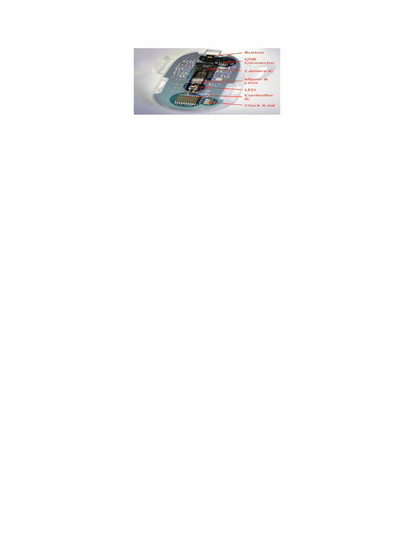
Working of Mouse:
Mouse is a computer’s peripheral device used along with the keyboard which allows a user to indicate what function he wants that his computer to carry out by selecting from a list of commands presented as a menu. The first mouse system was introduced for IBM PCs in 1982. With the help of mouse, the user points at a menu selection by physically moving the input device, which causes a core on screen movement of the cursor. One more button at the top of the mouse enables the user to indicate that he can select a menu item. The name mouse, originated at the Stanford Research Institute, derives from the resemblance of early models (which had a cord attached to the rear part of the device, suggesting the idea of a tail) to the common mouse.
A Computer Mouse
Types of mouse:
1. Mechanical Mouse: -
The design is based on a small boll that is fixed at the bottom and rotated as the mouse is pushed along the surface. Switches inside the mouse detect the movement in four directions (i.e. cores to two axes of 2-D system) and relay the direction of ball’s rotation to the host computer. This mouse requires that the user move it across a surface. The parts of mechanical mouse can break, so care must be taken.

Operation of Mouse:-The main goal of any mouse is to translate the motion of your hand into signals that the computer can use. Let's take a look inside a track-ball mouse to see how it works:
1. A ball inside the mouse touches the desktop and rolls when the mouse moves.
2. Two rollers inside the mouse touch the ball. One of the rollers is oriented so that it detects motion in the X direction, and the other is oriented 90 degrees to the first roller so it detects motion in the Y direction. When the ball rotates, one or both of these rollers rotate as well. The following image shows the two white rollers on this mouse:
3. The rollers each connect to a shaft, and the shaft spins a disk with holes in it. When a roller rolls, its shaft and disk spin. The following image shows the disk:
4. On either side of the disk there is an infrared LED and an infrared sensor. The holes in the disk break the beam of light coming from the LED so that the infrared sensor sees pulses of light. The rate of the pulsing is directly related to the speed of the mouse and the distance it travels.
5. An on-board processor chip reads the pulses from the infrared sensors and turns them into binary data that the computer can understand. The chip sends the binary data to the computer through the mouse's cord.
2. Optical Mouse:
In this type of mouse, instead of rotating the ball, a right-beam is used to detect movement across a specially designed mouse pad.
The mouse uses two pairs of LEDs and photodiodes at its bottom. One pair is oriented at the right angles with the other. The matching mouse pad is coated with an overlapped pattern of blue & yellow grids. Each pair of LED and photodiode detects the motion in either direction across one axis of the grid.

Practical- 6
Aim: To study different ports and slots.
These are situated on the backside of the cabinet to connect I/O devices. There are following types of ports in a computer.
PORTS
1. Serial Port: -It is nine pin connector used for connecting peripheral devices.
2. Parallel Port: - It is a twenty five-pin connector used for connecting peripheral devices. The parallel port may transfer data at more speed than a serial port because of 25 pins.
3. USB Port: - It is the Universal Serial Bus used for connecting peripheral devices. It is a four-pin connector.
4. RJ-45(Register Jacket) port: RJ-45 jacks and plugs have 8 pins. If you have a computer patch cable laying around, you can see them on the plug. (Those shiny metal lines on the end.) RJ-45's are sometimes referred to as 8P8C connectors. This stands for 8 Position (which describes the width) 8 Conductor (or 8 Connector depending on who you talk to). 5. Sound port: Commonly, It includes Line In, Line Out and MIC Socket.
6. VGA Port: It is 15 pin VGA connector use for connecting monitor/LCD/TFT with Cabinet.
7. Keyboard & Mouse port: It is a 9 PIN PS/2 connector use for connecting keyboard & mouse only.
8. The Infrared Data Association (IrDA) defines physical specifications communications protocol standards for the short-range exchange of data over infrared light, for uses such as personal area networks (PANs).
9. RF PORT: Radio frequency (RF) is the range of electromagnetic frequencies above the audio range and below infrared light (from 10kHz to 300GHz).
Common Peripherals
LPT PORT:
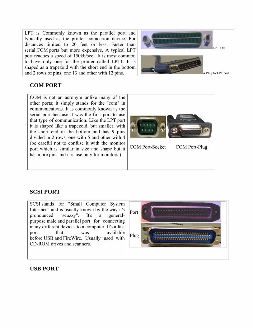
LPT is Commonly known as the parallel port and typically used as the printer connection device. For distances limited to 20 feet or less. Faster than serial COM ports but more expensive. A typical LPT port reaches a speed of 150kb/sec.. It is most common to have only one for the printer called LPT1. It is shaped as a trapezoid with the short end in the bottom and 2 rows of pins, one 13 and other with 12 pins.
LPI PORT
A Plug forLPT port
COM PORT
COM is not an acronym unlike many of the other ports; it simply stands for the "com" in communications. It is commonly known as the serial port because it was the first port to use that type of communication. Like the LPT port it is shaped like a trapezoid, but smaller, with the short end in the bottom and has 9 pins divided in 2 rows, one with 5 and other with 4 (be careful not to confuse it with the monitor port which is similar in size and shape but it has more pins and it is use only for monitors.)
COM Port-Socket COM Port-Plug
SCSI PORT
SCSI stands for "Small Computer System Interface" and is usually known by the way it's pronounced "scuzzy". It's a general-purpose male and parallel port for connecting many different devices to a computer. It's a fast port that was available before USB and FireWire. Usually used with CD-ROM drives and scanners.
Port
Plug
USB PORT
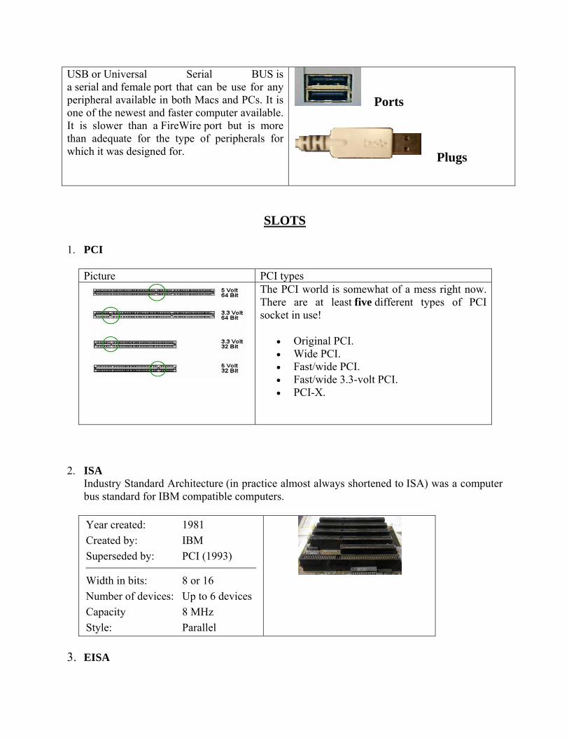
USB or Universal Serial BUS is a serial and female port that can be use for any peripheral available in both Macs and PCs. It is one of the newest and faster computer available. It is slower than a FireWire port but is more than adequate for the type of peripherals for which it was designed for.
Ports
Plugs
SLOTS
1. PCI
Picture PCI types
The PCI world is somewhat of a mess right now. There are at least five different types of PCI socket in use!
Original PCI. Wide PCI. Fast/wide PCI. Fast/wide 3.3-volt PCI. PCI-X.
2. ISA Industry Standard Architecture (in practice almost always shortened to ISA) was a computer bus standard for IBM compatible computers.
Year created: 1981
Created by: IBM
Superseded by: PCI (1993)
Width in bits: 8 or 16
Number of devices: Up to 6 devices
Capacity 8 MHz
Style: Parallel
3. EISA

The Extended Industry Standard Architecture (in practice almost always shortened to EISA and frequently pronounced "eee-suh") is a bus standard for IBM compatible computers.
Year created: 1988 Created by: Gang of Nine Superseded by: PCI (1993) Width in bits: 32 Number of devices: 1 per slot Capacity 8.33 MHz Style: Parallel
4. VESA
The VESA Local Bus (usually abbreviated to VL-Bus or VLB) was mostly used in personal computers.
5. IDE
Short for Integrated Drive Electronics or IBM Disc Electronics, IDE is more commonly known as ATA and is a standard interface for IBM compatible hard drives. IDE is different from the Small Computer Systems Interface (SCSI) and Enhanced Small Device Interface (ESDI) because its controllers are on each drive, meaning the drive can connect directly to the motherboard or controller.
6. SATA
The serial ATA or SATA computer bus, is a storage-interface for connecting host bus adapters to mass storage devices such as hard disk drives and optical drives.
Year created: 2003
Supersedes: Parallel ATA (PATA)
Capacity 1.5, 3.0, 6.0 Gbit/s
Style: Serial

Hotplugging? Yes
External? Yes (eSATA)
7. AGP The Accelerated Graphics Port (often shortened to AGP) is a high-speed point-to-point channel for attaching a video card to a computer's motherboard, primarily to assist in the acceleration of 3D computer graphics.
Year created: 1997
Created by: Intel
Superseded by: PCI Express (2004)
Width in bits: 32 Numberof devices:
1 device/slot
Capacity up to 2133 MB/s Style: Parallel Hotplugging? no
External? No
8. USB
USB (Universal Serial Bus) is as its name suggests, based on serial type architecture. However, it is an input-output interface much quicker than standard serial ports. Serial architecture was used for this type of port for two main reasons:
Serial architecture gives the user a much higher clock rate than a parallel interface because a parallel interface does not support too high frequencies (in a high speed architecture, bits circulating on each wire arrive with lag, causing errors);
serial cables are much cheaper than parallel cables.
USB standards
So, from 1995, the USB standard has been developed for connecting a wide range of devices.
The USB 1.0 standard offers two modes of communication:
12 Mb/s in high speed mode, 1.5 Mb/s in low speed.

Practical-7
Aim: To study various types of Cables & Connectors.
Cables
USB cables can be used to connect most new devices to your computer including flash memory sticks, portable media players, internet modems and digital cameras.
Computer accessories like mice, keyboards, webcams, portable hard-drives, microphones, printers, scanners and speakers can also be connected to the computer through USB ports. Additionally, USB cables are also used for charging a variety of gadgets including mobile phones or for transferring data from one computer to another.
1. Audio Cables and Connectors 3.5mm headphone jack
Digital Optical Audio
Picture
Uses A larger variety of the TSR connector, 1/4″ TRS, is commonly used in professional audio recording equipment
For high-end audio, like when you want to connect the output of a DVD player or a set-top box to a Dolby home theater, you need the

TOSLINK (or S/PDIF) connector.
2. Video Cables
VGA DVI Monitor Port
S-Video
Picture
Pin A standard VGA connector has 15-pins
A DVI cable has 29 pins.
Uses VGA cable is used to connect your laptop to a TV screen or a projector.
It allows DVI monitor to receive input from an HDMI cable.
These are commonly used for connecting DVD players, camcorders, older video consoles to the television.
3. Audio and Video Cables
RCA Connector Cables
HDMI Cables
DisplayPort
Picture
Resolution HDMI support a maximum resolution of 4096×2160p
It support resolutions up to 2560 × 1600 × 60 Hz.
Uses These are fiber optic cables and can therefore transmit pure digital audio through light.
HDMI is the new standard that provide both audio and video transmission through a single cable.
A combined digital video and audio cable that is more commonly used in computers is DisplayPort
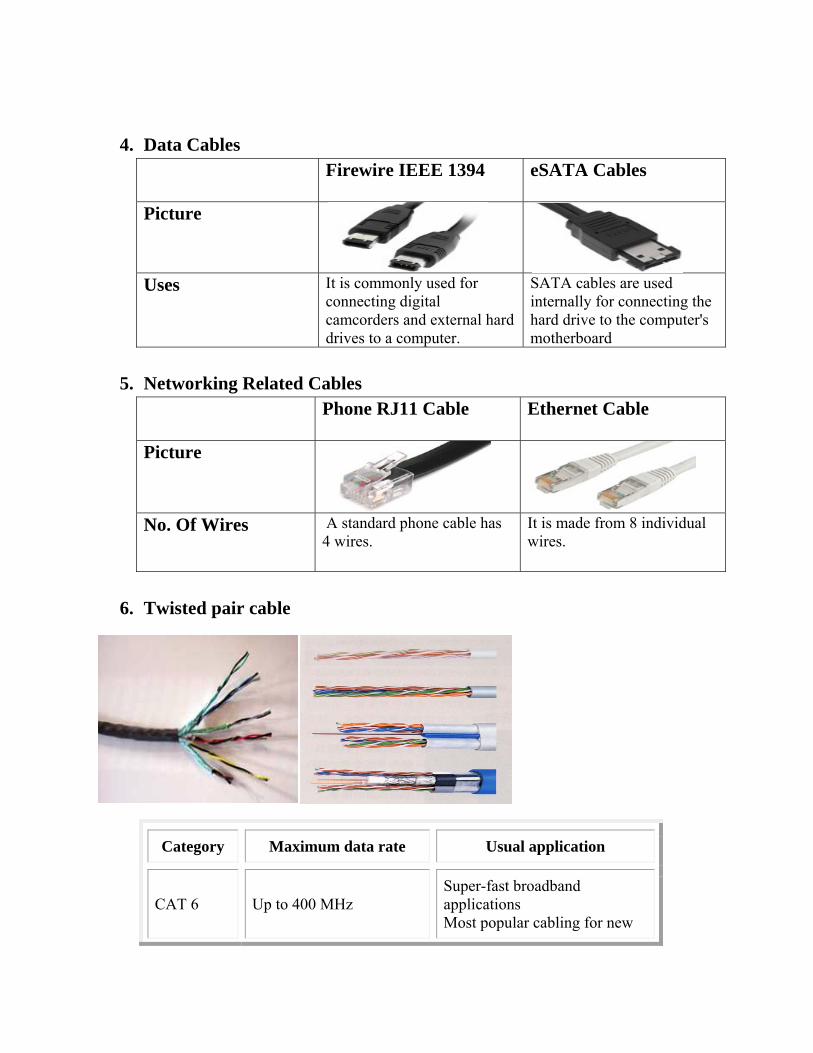
4. Data Cables Firewire IEEE 1394
eSATA Cables
Picture
Uses It is commonly used for connecting digital camcorders and external hard drives to a computer.
SATA cables are used internally for connecting the hard drive to the computer's motherboard
5. Networking Related Cables
Phone RJ11 Cable
Ethernet Cable
Picture
No. Of Wires A standard phone cable has 4 wires.
It is made from 8 individual wires.
6. Twisted pair cable
Category Maximum data rate Usual application
CAT 6 Up to 400 MHz Super-fast broadband applications Most popular cabling for new

installs
CAT 6E Up to 625 MHz (field-tested to 500 MHz)
Support for 10 Gigabit Ethernet (10GBASE-T)
CAT 7 (ISO Class F)
600-700 MHz 1.2 GHz in pairs with Siemon connector
Full-motion video Teleradiology Government and manufacturing environments Shielded system
Connectors
There are various types of connectors are used in a computer system. These connectors support various cables required for a number of operations. The connectors provided are:
1. Power Connector
2. Data Interface Connector
1. POWER CONNECTOR:
A power connector is an electrical connector designed to carry a significant amount of electrical power, usually as DC or low-frequency AC. Some types of RF connector may also carry large amounts of power, but are considered as a separate category. Connectors carrying small amounts of power are known as signal connectors.
Personal computer power supply connectors
Molex Berg ATX motherboard SATA Picture

No of pins 4 4 4 6 Uses Used for
powering CD-ROM drives, burners etc.
used by some hard drives, and carrying the same power supplies as the HDD connectors
It is now older AT-style connectors.
for connecting host bus adapters to mass storage devices
2. DATA INTERFACE CONNECTOR:
Modern hard disk drives use one of two interfaces: IDE (ATA) and its variants, or SCSI. You can tell immediately by looking at the back of the hard disk which interface is being used by the drive:
IDE/ATA SCSI Picture
No of pins 40 50,68 or 80 Shape rectangular D shaped
Keyboard Connector
The keyboard connector is the device at the end of the cable that is used to attach the keyboard to the system. The connector on the motherboard "stands up" from the surface of the board, making it rather fragile.
5-Pin DIN 6-Pin DIN USB Pin
Picture

Practical-8
Aim-Study of monitor.
MONITOR
Monitor Display Technology: -Often referred to as a monitor when packaged in a separate case, the display is the most-used output device on a computer. The display provides instant feedback by showing you text and graphic images as you work or play.
Most desktop displays use liquid crystal display (LCD) or cathode ray tube (CRT) technology, while nearly all portable computing devices such as laptops incorporate LCD technology. Because of their slimmer design and lower energy consumption, monitors using LCD technology (also called flat panel or flat screen displays) are replacing the venerable CRT on most desktop.
Common Display Standards and Resolutions:-
Standard Resolution Typical Use
XGA (Extended Graphics Array)
1024x768
15- and 17-inch CRT monitors 15-inch LCD monitors
SXGA (Super XGA)
1280x1024
15- and 17-inch CRT monitors 17-and 19-inch LCD monitors
UXGA (Ultra XGA)
1600x1200
19-, 20-, 21-inch CRT monitors 20-inch LCD monitors
QXGA (Quad XGA)
2048x1536 21-inch and larger CRT monitors
WXGA (Wide XGA)
1280x800 Wide aspect 15.4-inch laptops LCD displays
WSXGA+ (Wide SXGA plus)
1680x1050 Wide aspect 20-inch LCD monitors
WUXGA (Wide Ultra XGA)
1920x1200 Wide aspect 22-inch and larger LCD monitors

LCD
Stands for "Liquid Crystal Display." LCDs are super-thin displays that are used in laptop computer screens and flat panel monitors. Smaller LCDs are used in handheld TVs, PDAs, and portable video game devices. The image on an LCD screen is created by sandwiching an electrically reactive substance between two electrodes. This color of this substance can be changed by increasing or reducing the electrical current. Since LCD screens are based on the principle of blocking light (rather than emitting it), they use up much less power than standard CRT (Cathode-Ray Tube) monitors.
LED
Stands for "Light-Emitting Diode." An LED is an electronic device that emits light when an electrical current is passed through it. Early LEDs produced only red light, but modern LEDs can produce several different colors, including red, green, and blue (RGB) light. Recent advances in LED technology have made it possible for LEDs to produce white light as well. LEDs are commonly used for indicator lights (such as power on/off lights) on electronic devices. They also have several other applications, including electronic signs, clock displays, and flashlights. Since LEDs are energy efficient and have a long lifespan (often more than 100,000 hours), they have begun to replace traditional light bulbs in several areas.
Diff. b/w LCD and LCD:-
Monitor LCD LED Picture
Contrast It has lower contrast than LCD and LED.
LCD is not better then LED.
Contrast and Black level of the LED screen is better than the LCD screens
Color accuracy
Almost same of LED. Color accuracyfor direct and edge LED displays and LCD displays are almost same but the RGB

LEDs display has quite better color accuracy
Viewing Angle
If the viewing angle of the display is much wider than thirty degrees from the center then the contrast ratio of the image is diminished in LCD.
LEDs have a wider viewing angle, which means the image is still clear when viewed from the side.
Power It consume more power than LCD and LED. The high power consumption results in high power consumption of cathode ray tube.
Less power is consumed by LCD.
More power is consumed by the local dimming LED display than LCD.
Use of Mercury
LCD use mercury. LED displays do not use mercury (used in cathode lamps in LCD backlight) so they are environment friendly.
Size Size is more than LCD and LED.
LCD size is more then that of LED.
The size of Edge and RGB monitors is slightly thinner than the LCD monitors.
Price These costs about 2-3 times lesser than LCD and LED.
This advantage further beats the retail price up of a television with an LCD display.
LED displays yield a higher price tag, which reflects their efficiency and the better picture quality. LED displays also allow for thinner, lighter televisions.

Practical-9
Aim: To study different types of printers.
The machine through which any type of data in the computer can be print on a paper is called Printer.
Different Types Of Printers
A printer can make a great addition to any home or office. Printers can be used for used for numerous reasons in a household, or and office. Having a printer is great for individuals, families and businesses because they can be used to print off directions, emails, work papers, charts, student papers, research, photos and much more. Printers are a great way to get the information you have on your computer onto a piece of paper in a very quick amount of time.
There are many makes and models of printers making it hard to even know where to start from.
Types of Printers
1. Laser Printer
A laser printer rapidly produces high quality text and graphics on a regular piece of computer paper, and it is the most common computer printer used today. Laser printers can vary in speed with some of the fastest models being able to print over 12,000 pages per hour
2. Inkjet Printer
Inkjet printers operate by propelling variably sized droplets of liquid or molten ink onto a piece of computer paper. Ink jet printers are the most common type of printers used by the general consumer due to their low cost, high quality printing, and capability of printing in different colors

3. Multifunctional Printer
Multifunctional printers are also known as an MFP which is a printer that incorporates the ability to function multiple devices in one. The advantage to this is to one save money from buying all kinds of office devices when you can buy a printer capable of doing all these tasks.
4. Solid Ink Printer
Solid ink printers are also known as phase change printers can produce excellent results. They are a type of thermal transfer printer that uses solid sticks of colored ink that are very similar to candle wax. The sticks of ink are melted and fed into a crystal operated print head, which sprays the ink on the rotating oil coated drum
5. Dye Sublimation Printer
A dye Sublimation printer is a printer that uses a printing process of heat to transfer dye to a medium plastic, paper or canvas. The process is usually done to lay one color at a time using a ribbon that has color panels.
6. Thermal Printer

Thermal printers work by selectively heating regions of special heat sensitive paper. Monochrome thermal printers are used in cash registers, ATMs, gasoline dispensers and some older inexpensive fax machines. The color on the paper can be achieved with special papers and different heating temperatures.
7. Dot Matrix Printer
A Dot matrix printer is an impact printer that produces text and graphics when tiny wire pins one a print head strike a ink ribbon. The print head runs back and forth on the paper like a type writer.
8. Large Format Printer
A large format printer is any printer with a print between 17 inches and 100 inches. Large format printers are used to print such things as banners, posters, and other large printable objects. Large format printer generally use a roll of print material rather than individual printing sheets.
9. LED/LCD printers
are types of electro photographic printers that are identical to laser printers in most ways. Both LCD (liquid crystal display) and LED (light-emitting diode) printers use a light source instead of a laser to create an image on a drum. In most contexts, "laser printer" covers LCD and LED printers as well.

10. Portable printers
are usually fairly lightweight and sometimes carry the option of using a battery instead of drawing power from the computer. Usually they realize basic print resolutions suitable for plain text printing. Thermal printer, Thermal transfer printer and Ink-Jet printer. The main advantage of thermal and thermal transfer printers is that they can be very small.
11. Plotters
are large-scale printers that are very accurate at reproducing line drawings. They are commonly used for technical drawings such as engineering drawings or architectural blueprints. The two basic types of plotters are called flatbed plotters and drum plotters.
12. Digital Photo printers
Many middle range printers are now able to print photo quality images. Usually an option with color printers, specialist photo print heads allow a greater resolution to be achieved to improve photo image quality. Photo ink jet printers expand their gamuts by adding additional ink colors, usually light cyan and light magenta.
13. Network printer
is a printer that provides output capabilities to all network users.
14. The Bravo AutoPrinter
is the worlds first automated CD/DVD printing system that can truly be called innovative. It combines automatic, robotic-based CD or DVD printing along with full-color, 2400 dpi disc printing all in one compact, desktop unit.

15. Printers for banking:
these printers realize innovative technology and functionality to increase productivity, and reduce costs.
16. EZ CD/DVD Printers:
provide a low cost way to create professional printed CD-Rs and DVD-Rs. Instead of writing on the CD or applying labels, you can print directly on the CD surface! With high speed capabilities, a full color image can be printed directly on the top surface of your CDs in less than 1 minute.
17. Label Printers
are the smartest way to print labels one at a time. The printers allow easy installation. You can get high-quality, professional results every time.
18. VersaLaser™
is peripheral tool, that can transform images or drawings on your computer screen into real items made out of an amazing variety of materials… wood, plastic, fabric, paper, glass, leather, stone, ceramic, rubber… and it’s as easy to use as your printer. 2 models of VersaLaser have 16"x12"(VL-200) and 24"x12" (VL-300) work areas.
19. 3D Printers
The ZPrinter 310 System creates physical models directly from computer-aided design system (“CAD”) and other digital data in hours instead of days. The printer is fast, versatile and simple, allowing engineers to produce a range of concept models and functional test parts quickly and inexpensively. The system is ideal for an office environment or educational institution, providing product developers easy access to a 3D Printer.

Practical-10
Aim:- To assemble a PC.
The main components required to assemble a PC are as follows:
Mains Power
Floppy Drive
SMPS
Motherboard
Hard Disk
RAM
Processor
Display Card
Mouse and Keyboard cables
Monitor cables

Practical-11
Aim: To study Floppy Disk Drive.
The floppy disk drive (FDD) was the primary means of adding data to a computer until the CD-ROM drive became popular. In fact, FDDs have been a key component of most personal computers for more than 20 years. Basically, a floppy disk drive reads and writes data to a small, circular piece of metal-coated plastic similar to audio cassette tape.
Procedure:
1. Switch off the main power supply.
2. Take out the data bus & the power supply from the FDD, gently.
3. Unscrew the FDD & take it out with extreme care.
4. Now put the FDD back in & screw up.
5. Plug in the data bus & power supply & make sure that the connections are precise
Parts of a Floppy Disk Drive:
The Disk
A floppy disk is a lot like a cassette tape:
Both use a thin plastic base material coated with iron oxide. This oxide is a ferromagnetic material, meaning that if you expose it to a magnetic field it is permanently magnetized by the field.
Both can record information instantly. Both can be erased and reused many times. Both are very inexpensive and easy to use.

FIG: The DiskFloppy drive
The major parts of a FDD include:
Read/Write Heads: Located on both sides of a diskette, they move together on the same assembly
Drive Motor: A very small spindle motor engages the metal hub at the center of the diskette, spinning it at either 300 or 360 rotations per minute (RPM).
Stepper Motor: This motor makes a precise number of stepped revolutions to move the read/write head assembly to the proper track position. The read/write head assembly is fastened to the stepper motor shaft.
Mechanical Frame: A system of levers that opens the little protective window on the diskette to allow the read/write heads to touch the dual-sided diskette media. An external button allows the diskette to be ejected, at which point the spring-loaded protective window on the diskette closes.
Circuit Board: Contains all of the electronics to handle the data read from or written to the diskette. It also controls the stepper-motor control circuits used to move the read/write heads to each track, as well as the movement of the read/write heads toward the diskette surface.
Writing Data on a Floppy Disk
The following is an overview of how a floppy disk drive writes data to a floppy disk. Reading
data is very similar. Here's what happens:
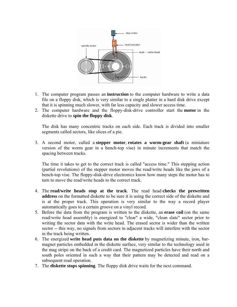
1. The computer program passes an instruction to the computer hardware to write a data file on a floppy disk, which is very similar to a single platter in a hard disk drive except that it is spinning much slower, with far less capacity and slower access time.
2. The computer hardware and the floppy-disk-drive controller start the motor in the diskette drive to spin the floppy disk.
The disk has many concentric tracks on each side. Each track is divided into smaller segments called sectors, like slices of a pie.
3. A second motor, called a stepper motor, rotates a worm-gear shaft (a miniature version of the worm gear in a bench-top vise) in minute increments that match the spacing between tracks.
The time it takes to get to the correct track is called "access time." This stepping action (partial revolutions) of the stepper motor moves the read/write heads like the jaws of a bench-top vise. The floppy-disk-drive electronics know how many steps the motor has to turn to move the read/write heads to the correct track.
4. The read/write heads stop at the track. The read head checks the prewritten address on the formatted diskette to be sure it is using the correct side of the diskette and is at the proper track. This operation is very similar to the way a record player automatically goes to a certain groove on a vinyl record.
5. Before the data from the program is written to the diskette, an erase coil (on the same read/write head assembly) is energized to "clear" a wide, "clean slate" sector prior to writing the sector data with the write head. The erased sector is wider than the written sector -- this way, no signals from sectors in adjacent tracks will interfere with the sector in the track being written.
6. The energized write head puts data on the diskette by magnetizing minute, iron, bar-magnet particles embedded in the diskette surface, very similar to the technology used in the mag stripe on the back of a credit card. The magnetized particles have their north and south poles oriented in such a way that their pattern may be detected and read on a subsequent read operation.
7. The diskette stops spinning. The floppy disk drive waits for the next command.

FIG: (Open Circuit of floppy Derive)
Applications:
Floppy disks, while rarely used to distribute software (as in the past), are still used in these
applications:
1. In some Sony digital cameras
2. For software recovery after a system crash or a virus attack
3. When data from one computer is needed on a second computer and the two computers are not
networked.
4. In bootable diskettes used for updating the BIOS on a personal computer
5. In high-density form, used in the popular Zip drive.
.