snmp web card - - aps onduleur batterie · 1 about this user manual welcome to the user manual for...
TRANSCRIPT

Intellislot SNMP / Web Card
for use with the PowerSure, GXT & Nfinity UPS
User ManualEnglish
TM®
TM
INTRODUCTION ..................................................................................... 1About this User Manual ..................................................................... 1About the Quick Start Guide ............................................................. 1About the Text Formatting ................................................................ 1Introduction ....................................................................................... 2
INSTALLATION ...................................................................................... 5Installing the Card ............................................................................. 5Connecting the Card to the Network ................................................. 5Configuring the Card ......................................................................... 6
SERVICE TERMINAL ............................................................................. 7Opening a Service Terminal Connection .......................................... 7Main Menu ........................................................................................ 9System Information Menu ............................................................... 10Network Interface Menu .................................................................. 11SNMP Communication Menu .......................................................... 13Web Server Menu ........................................................................... 16Firmware Updates Menu ................................................................. 17Factory Settings Menu .................................................................... 18
WEB ...................................................................................................... 19Opening a Web Connection ............................................................ 19Connected Device Information ........................................................ 21Security ........................................................................................... 22Before clicking Save and Reboot .................................................... 23After clicking Save and Reboot ....................................................... 24Monitor Tab ..................................................................................... 26Control Tab ..................................................................................... 28Configure Tab ................................................................................. 29Support Tab .................................................................................... 32
SNMP .................................................................................................... 33
APPENDICES ....................................................................................... 35MultiLink Support ............................................................................ 35Nfinity™ Support ............................................................................. 37
TABLE OF CONTENTS
1
About this User ManualWelcome to the User Manual for the Intellislot SNMP/Web Card. Thismanual is available from Liebert's web site at www.liebert.com. The mostrecent version is always located online and you should consult the Web ifyou feel you have an older copy.
About the Quick Start GuideIn the Appendices, you will find a copy of the Quick Start Guide. TheQuick Start Guide ships in the box with the Intellislot SNMP/Web Cardand provides the most important information you need to install and con-figure of the card. It included with this manual for your reference.
About the Text Formatting·Whenever a Liebert product is referred to, the product name appears inItalics.·Text from Service Terminal screens is shown using Courier.·Text representing tabs and folders on the Web interface are show inbold.·Text that you need to enter from the keyboard is also shown using Cou-rier and the required text is in quotations.
INTRODUCTION

2
Introduction
The Intellislot SNMP/Web Card delivers SNMP (Simple Network Manage-ment Protocol) and Web support to the UPS in which it is installed. Thecard is designed for use in a Liebert UPS with an Intellislot bay. Thisincludes the PowerSure Interactive, UPStation GXT, UPStation GXT2U,and Nfinity.
The Intellislot SNMP/Web Card requires an Ethernet network connectionand supports both 10Mbit and 100Mbit communication speeds and eitherhalf or full duplex.
The Intellislot SNMP/Web Card enables in-band communication via theWeb from computers running web browser software.
The Intellislot SNMP/Web Card enables in-band communication with net-work management systems (NMS) via SNMP.
The Intellislot SNMP/Web Card integrates with Liebert's MultiLink™ soft-ware to provide notification for unattended, graceful operating systemshutdown of PCs, servers, and workstations. MultiLink is available formost operating systems. For more information on MultiLink and down-loadable version of MultiLink software, please visit www.liebert.com.

5
Installing the Card
The Intellislot SNMP/Web Card is hot swappable and user-serviceable.You do not need to turn off the UPS, disconnect any loads, or restart theUPS to install or remove the card.
CAUTION: The Intellislot Bay is located in close proximity to theUPS' output and the UPS' electrical receptacles. Whenever pos-sible, you should turn the UPS OFF when installing the card.
To install the card:
1.Locate the Intellislot bay on the back of the UPS. For Nfinity,use the Intellislot labeled "COM1".2.Remove the plastic Intellislot cover and save the screws forStep 4.3.Insert the Intellislot SNMP/Web Card into the Intellislot bay.4.Secure the card with the screws you removed in Step 2.
NOTE: The card is powered by the UPS during both normal andon battery operation. If the UPS is ON, the card will operate nor-mally after a brief boot up period.
Connecting the Card to the NetworkTo connect the card to the network, simply plug an Ethernet cable to theRJ-45 connector on the card.
The card supports 10Mbit and 100Mbit communication speeds at eitherhalf or full duplex. The card ships from the factory in an auto-sensingmode. In this mode, the card works to negotiate the optimal setting foryour network environment. To turn off the auto-sensing mode and forcethe card's communication speed or duplex setting, you will need to open aService Terminal connection to the card. Please refer to the Service Ter-minal section.
INSTALLATION

6
Configuring the CardThe card ships from the factory with DHCP service enabled. The MACaddress is located on the outside of the box and is also printed on asticker affixed to the top of card.
To give the card a static IP address, you will need to open a Service Ter-minal connection to the card. Please see the following section for moreon the Service Terminal.

7
Opening a Service Terminal ConnectionThis section covers the Service Terminal in detail. From the Service Ter-minal, you can configure all settings of the card.
NOTE: You can also configure many of the settings discussed inthis section from the Web. To specify that the card communicateat either 10Mbit or 100Mbit instead of it trying to auto-negotiate,you must use the Service Terminal
You access the Service Terminal by opening a direct serial connection tothe Intellislot SNMP/Web Card.
1.Locate the blue serial configuration cable that shipped with thecard.
NOTE: If you have misplaced the cable provided, youcan use a null modem cable with a DB-9F connector atboth ends.
2.Connect one end of the blue serial configuration cable to the DB-9Mserial port on the Intellislot SNMP/Web Card.
3.Connect the other end of the blue serial configuration cable to a ter-minal or a PC running terminal emulator software, like HyperTermi-nal™ or ProComm™.
NOTE: If you are using a laptop or PC without any con-nected serial devices, your active serial port is most likelyCOM1. If you have the correct cable and are unable toopen a connection, please confirm that you do not havea COM port conflict.
4.Use the following communication settings:
BAUD RATE: 9600DATA BITS: 8PARITY: NONESTOP BITS: 1FLOW CONTROL: NONE
5. Press "Enter" to see the Main Menu.
SERVICE TERMINAL

8
If you do not see the Main Menu, press "Enter" again several times. Ifthe Main Menu fails to appear, confirm that the blue configuration cable isinstalled properly, that your PC or terminal COM port is active, and thatyou are using the correct communication settings. If, after verifying thecable and your communication settings are correct you still do not see theMain Menu, reinstall the card in the Intellislot bay.
NOTE: The card is powered by the UPS. If the UPS is ON, thecard will operate automatically. If you have the cable connectedwhile inserting the card, you will see initialization text scroll onyour screen. If the card has already been powered, you will notsee this information.

9
Main MenuFrom the Main Menu screen, you will find configuration information func-tionally grouped.
Liebert Network Interface Card
Main Menu----------1: System Information2: Network Interface3: SNMP Communications4: Web Server5: Firmware Updates6: Factory Settings
q: Quit and abort changesx: Exit and save
Please select a key ?>
Changes you make using the Service Terminal will only take effect afterthe card reboots.
Accordingly, you always need to return to the Main Menu screen aftermaking any change(s) and then select either option "q" or "x". If youselect option "q" your changes will be aborted and the card will retain itsprevious settings. If you select option "x" the card will reboot and restartwith your changes.

10
System Information MenuSelecting option "1" from the Main Menu opens the System InformationMenu.
Liebert Network Interface Card
System Information Menu------------------------1: Name Data Room UPS2: Contact Network Services x1003: Location Building 2, Floor 44: Description Supporting Main Server
<ESC>: Cancel menu level
Please select a key ?>
The System Information Menu contains four user-defined data fields. TheService Terminal will report Uninitialized where you have notentered personalized data. The System Information Menu allows you toenter useful location and contact information. The data in these fields isavailable via SNMP and is presented in the support tab on the Web page.
A typical configuration includes:
Selecting option "1" to assign a name to the UPS.Selecting option "2" to assign an administrative contact Selecting option "3" to assign location information.Selecting option "4" to assign a description.
The Name field can be up to 255 characters in length. The Contact,Location, and Description fields can be up to 64 characters in length.
If you have made a change, you need to press "Esc" to return to the MainMenu and then press "x" to exit and save changes.

11
Network Interface MenuSelecting Option "2" from the Main Menu opens the Network InterfaceMenu.
Network Interface Menu-----------------------1: Speed/Duplex Auto2: Boot mode DHCP IP Address 126.4.1.19 Netmask 255.255.255.0
<ESC>: Cancel menu level
Please select a key ?>
From the Network Interface Menu you can configure the Network settingsof the card
Select option "1" to change the communication speed of the card or theduplex setting.
Please select a key ?> 1 Valid Selections: ------------------ 1. Auto 2. 10Mbs/Half Duplex 3. 10Mbs/Full Duplex 4. 100Mbs/Half Duplex 5. 100Mbs/Full DuplexSelect Speed and Duplex Setting:
The Speed/Duplex default setting is Auto and the card attempts to negoti-ate the optimal setting for your network environment. You can select afixed setting for either 10Mbit or 100Mbit speed, at either full or halfduplex.

12
Select option "2" to change Boot mode settings of the card.
Valid Selections: ------------------ 1. Static 2. BootP 3. DHCPSelect Boot Mode:
Your Boot mode setting options are Static, BootP, and DHCP. The cardships from the factory with DHCP service enabled. DHCP allows the cardto obtain an address dynamically from a DHCP server on your network.The card also supports BootP dynamic configuration. If you are usingDHCP or BootP you may find want to configure your DHCP or BootPserver with the MAC Address of the card so that the server alwaysassigns the card a specific address. The MAC Address is printed on asticker affixed to the top of the card.
To assign the card a fixed IP address, you need to change the Boot modeto Static and then provide an IP Address, Netmask, and Default Route.
Network Interface Menu-----------------------1: Speed/Duplex Auto2: Boot mode Static3: IP Address 126.4.1.1024: Netmask 255.255.255.05: Default Gateway 126.4.1.1
If you have made a change, you need to press "Esc" to return to the MainMenu and then press "x" to exit and save changes.

13
SNMP Communication MenuSelecting Option "3" from the Main Menu opens the SNMP Communica-tions Menu.
Liebert Network Interface Card
SNMP Communications Menu-------------------------1: Authentication Traps 'no'2: Display/Modify Communities3: Display/Modify Trap Communities
<ESC>: Cancel menu level
Please select a key ?>
From the SNMP Communications Menu you can configure the SNMP set-tings and behavior of the card.
Select option "1" to turn authentication traps on or off. Enter "y" to enableauthentication traps. Enter "n" to disable authentication traps.
Select option "2" to edit the list of devices you want to have access to thecard via SNMP.
Display/Modify Communities Menu--------------------------------
1: 126.4.1.100 write MyCommunity
<ESC>: Cancel menu level<a>dd <d>elete <e>dit
Complex lines allowed. e.g. <a 198.1.1.1 write public> ?>
The options "a" "d" and "e" allow you to manage your list of networkdevices with access to the card. These options can be used as a com-

14
plex instruction to add a single device, specify read/write access rights,and designate the Community String. For, example, entering:
"a 126.4.1.200 read NewCommunity"
adds device 126.4.1.200 to the community list. The menu will update:
Display/Modify Communities Menu--------------------------------
1: 126.4.1.100 write MyCommunity 2: 126.4.1.200 read NewCommunity
<ESC>: Cancel menu level<a>dd <d>elete <e>dit
As you are adding communities, you need to consider access rights.Notice above, that 126.4.1.100 has write access when the device passesthe correct Community String of MyCommunity. This means that this net-work device has both read and write access to the card, whereas126.4.1.200 has only the ability to read information when providing thecorrect Community String. Devices with write access can control the UPSand reconfigure settings of the card. In order for a device you have addedto the Communities Menu to also receive notification from the card viaSNMP Traps for UPS alarms and condition changed, you also need toadd the device to the Trap Communities Menu. See below for details.
Select option "3" to edit the list of devices you want to receive traps fromthe card via SNMP.
Display/Modify Trap Communities Menu-------------------------------------
1: 126.4.1.100 MyCommunity
<ESC>: Cancel menu level<a>dd <d>elete <e>dit
Complex lines allowed. e.g. <a 198.1.1.1 public> ?>
The options "a" "d" and "e" allow you to manage you list of networkdevices that will receive SNMP Traps from the card. These options can

15
be used as a complex instruction to add a single device and designate theCommunity String. For, example, entering:
"a 126.4.1.200 NewCommunity"
adds device 126.4.1.200 to the trap community list. The menu will update:
Display/Modify Trap Communities Menu-------------------------------------
1: 126.4.1.100 MyCommunity 2: 126.4.1.200 NewCommunity
<ESC>: Cancel menu level<a>dd <d>elete <e>dit
It is important to remember that you will often need to add a networkdevice to both the Communities Menu and the Trap Communities Menufor your SNMP implementation to work as designed.
If you have made a change, you need to press "Esc" to return to the MainMenu and then press "x" to exit and save changes.

16
Web Server MenuSelecting Option "4" from the Main Menu opens the Web Server Menu.
Web Server Menu----------------1: Web Server 'enabled'2: Change Username/Password
<ESC>: Cancel menu level
Please select a key ?>
From the Web Server Menu you can enable/disable the Web functionalityof the card and edit the User Name and Password, which regulate accessto the Web control and configuration tabs.
Select option "1" to turn the entire Web Server ON or OFF.
NOTE: If you select disabled, the card will be totally inaccessiblefrom the Web, although it will continue to operate as an SNMP-only agent.
Select option "2" to edit the User Name or Password that must both beentered correctly to control the UPS or to change configuration settings ofthe card from the Web.
The factory default User Name is “Liebert” and the Password is “Liebert”.Because this is a well-known username and password, you shouldchange it as soon as possible. You can also change the User Name orPassword from the Web.
From the service terminal, you do not need to know the current UserName or Password to make a change.
NOTE: When changing the Username of Password from the Ser-vice Terminal, it is possible to leave either field blank. If you omiteither the Username or Password field, the Service Terminal willaccept the input but it will set the response to the default of Lie-bert.
If you have made a change, you need to press "Esc" to return to the MainMenu and then press "x" to exit and save changes.

17
Firmware Updates MenuSelecting Option "5" from the Main Menu opens the Firmware UpdatesMenu.
Firmware Updates Menu----------------------1: Initiate XMODEM session...
<ESC>: Cancel menu level
Please select a key ?>
From the Firmware Updates Menu you can reload the firmware of thecard. Please consult the instructions you downloaded or received withyou new firmware version.

18
Factory Settings MenuSelecting Option "6" from the Main Menu opens Factory Settings Menu.
Factory Settings Menu----------------------1: Reset to Factory Defaults
Manufacture Date OCT 27,2000 MAC Address 00-00-68-16-00-03 Serial Number 415981G101D2000OCT270003
<ESC>: Cancel menu level
Please select a key ?>
The Factory Settings Menu displays information you may be asked byLiebert Technical Applications Support and is the only electronic placeyou can access the MAC address on demand. From the menu, you alsohave the option of resetting all the settings of the card the factory default.Selecting "1" will likely cause the card to be inaccessible from the networkso its use should be applied with caution.
If you have made a change, you need to press "Esc" to return to the MainMenu and then press "x" to exit and save changes.

19
Opening a Web ConnectionThis section explains the Web interface in detail. From the Web, you canmonitor and control the UPS in which the card is installed. You can alsoconfigure many settings of the card.
NOTE: To specify that the card communicates at either 10Mbit or100Mbit, instead of it trying to auto-negotiate, you must use theService Terminal.
You access the Web Interface of the Intellislot SNMP/Web Card by open-ing a direct web browser. The card utilizes functionality of Microsoft®Internet Explorer™ 5.0 or higher. Whenever possible, you should use thelatest copy of IE.
1. Open Internet Explorer.2. Enter the IP address or hostname of the card in the address line
of your browser.
The first page you will see every time you open a new Web connection tothe card is the Power Flow folder in the monitor tab. After your browserconnects, you will see a screen very similar to below:
WEB

20
You will notice that information on the Web page is grouped in Tabs andFolders. The card organizes similar information together in folders, andsimilar functions in tabs.
Tabs: Across the top of the screen are four tabs: monitor, con-trol, configure, and support. As the tab names suggest, differ-ent information is presented and different operations are availableto you under each tab.
Folders: Within each tab, you will see a different list of folders onleft pane of your screen. Here, display, control, and configurationinformation is grouped logically. If, for example, you click theInput folder under the monitor tab, you will see only informationabout the UPS' input power.

21
Connected Device InformationClicking between the monitor, contol, configure, and support tabsgives you access to folder lists on the bottom of the left pane. Althoughthe folder list changes, depending on the tab selected, the top portion ofthe left pane remains constant. In the top of the left pane, summary net-work and connected UPS status is always presented.
The IP address of the card and the Liebert UPS model type is presentedunder Connected Device:. In this example, the Intellislot SNMP/WebCard is installed in a UPStation GXT 700VA UPS and has been assignedthe IP address, 126.4.20.92.
The current operating state of the UPS is presented under ConnectedDevice Status: along with the most serious UPS alarm, if one is present.For our example above, the UPS is operating normally with good utilitypower.
22
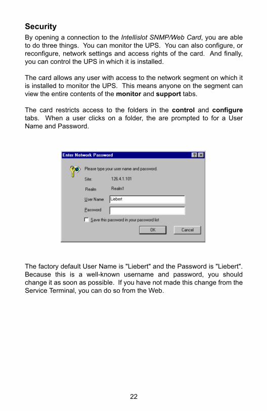
SecurityBy opening a connection to the Intellislot SNMP/Web Card, you are ableto do three things. You can monitor the UPS. You can also configure, orreconfigure, network settings and access rights of the card. And finally,you can control the UPS in which it is installed.
The card allows any user with access to the network segment on which itis installed to monitor the UPS. This means anyone on the segment canview the entire contents of the monitor and support tabs.
The card restricts access to the folders in the control and configuretabs. When a user clicks on a folder, the are prompted to for a UserName and Password.
The factory default User Name is "Liebert" and the Password is "Liebert".Because this is a well-known username and password, you shouldchange it as soon as possible. If you have not made this change from theService Terminal, you can do so from the Web.

23
Before clicking Save and Reboot Just as you discovered when using the Service Terminal, every time youmake a configuration change, the card must reboot for that change totake effect. Making changes from the Web is the same. As you navigatebetween the card's web pages, you will notice that configuration screensinclude buttons with text Save and Reboot.
As an example, the screen shot below shows the edit fields availableunder the configure tab when you select the Network folder:
When you click any of the web page Save and Reboot buttons, the cardsaves any changes you have made and then restarts. During this time,the card is unavailable on the network. When this process begins, yourweb browser may be instructed to open a new page.

24
After clicking Save and RebootAnytime you press a Save and Reboot button on any of the card's webpages, the card will reinitialize. During this time, the card is unavailableon the network. As the card reboots, it first begins communicating on thenetwork and then establishes communications with the UPS in which it isinstalled. The card will present to you some helpful information during theperiod of time that it is restarting.
You will usually see the following text after you click a Save and Rebootbutton:
Redirecting due to user configuration change!
This text will remain on the screen for several seconds. When the cardserves this text to your web browser it also passes instructions for thebrowser to wait and then attempt to refresh. If, however, this text persists,you may need to manually click the browser's Refresh button.
As the card continues the reboot process, you may see the following textdisplayed:
Discovering connected device...
Last updated: Monday ...
This text is shown after the card has successfully connected to the net-work and is operating normally, but has yet to complete opening a con-nection to the UPS.
As the card reboots, your active page may remain blank for a brief periodof time, your web browser may give an unable to connect warning, or itmay continue to display one of the messages above. Due to some timingissues with networks and static nature of browsers, you may need to clickthe browser's Refresh button. Your refresh will take you to the PowerFlow folder in the monitor tab.
NOTE: If the “Discovering connected device...” text persists, evenafter clicking the browser's Refresh button, and you are neverpresented a graphical UPS page, the card is receiving power and

25
operating properly but it is having problems communicating withthe UPS.
When you make changes to the network address setting of the card, yourweb browser will be redirected to the new address and the browser willopen a new window.
If you change from a Static IP address to either DHCP or BootP, you willreceive the following warning.
The card has rebooted to an unknown dynamic address!
Please consult a network administrator for the address!
You may know the address the card will be assigned by your BootP orDHCP server. In this case, simply enter that address into your webbrowser and reconnect. Logically, the card has no way of knowing whatthe new address will be if you change from Static to BootP or DHCP.Although this feature is made available to you from the Web, you shoulduse caution when making the change.

26
Monitor TabWhen you select the monitor tab, you are presented with ConnectedDevice: and Connected Device Status: on the top of the left pane. Thefolder list is at the bottom of the pane under Device Information:.
The first page you will see every time you open a new Web connection tothe card is the Power Flow folder in the monitor tab. After your browserconnects, you will see a screen very similar to below:
From the monitor tab, you are able to view the parametric data of theUPS.
The Power Flow folder provides a graphical representation of the currentstate of the UPS along with useful information about input, output, andbattery voltages as well as battery runtime information.
The Alarm folder provides a list or any present UPS alarms.

27
Clicking on the Battery, Output, Input, Bypass (not supported in Power-Sure Interactive), or Internals folder replaces the summary data pre-sented on the graphical power flow pane with a tabular view of thecomplete list of data points reported by the UPS. Clicking on the Inputfolder presents a screen similar to:
In the tabular view data, like input voltage, that changes over time isgrouped as a Parameter. Values, which are known to the UPS, like nom-inal input frequency, are reported in Information. Finally, conditionparameters, like utility failed, are together in a table labeled, Condition.The list of data in each of these sections and folders varies across UPSproduct lines and sizes and will change depending on the UPS in whichyou have installed the card.

28
Control TabWhen you select the control tab, you are presented with ConnectedDevice: and Connected Device Status: on the top of the left pane. Thefolder list is at the bottom of the pane under Control Operations:.
As detailed in the Web Security section, a Username and Password pro-tect the folders in the control tab.
From the control tab you can do things like turn the UPS' output ON orOFF. Each folder represents a different control behavior and this list willvary across UPS product lines and sizes.

29
Configure TabWhen you select the configure tab, you are presented with ConnectedDevice: and Connected Device Status: on the top of the left pane. Thefolder list is at the bottom of the pane under Configuration Categories:.
As detailed in the Web Security section, a Username and Password pro-tect the folders in the configure tab.
When you click on a folder under Configuration Categories: you will beable to edit network and device settings, including SNMP community lists.The folder list is shown below:
Device InfoClicking on the Device Info folder allows you to edit the Name, Contact,Location, and Description fields.
Factory DefaultsClicking on the Factory Defaults folder allows you to reset the card to thefactory settings.
NetworkClicking on the Network folder allows you edit the IP address, Subnet,and Default Route of the card. You are also able to change the bootmode setting of Static IP, DHCP, or BootP.

30
SNMPClicking on the SNMP folder allows you to enable authentication traps.
Clicking on the Access or Traps folder allows you to configure thedevices you want to have access to the card via SNMP and devices youwant to receive traps from the card. An example configuration in theAccess folder is shown below:
As you are adding communities, you need to consider access rights.Notice above, that 126.4.1.100 has write access when the device passesthe correct Community String of MyCommunity. This means that this net-work device has both read and write access to the card, whereas126.4.1.200 has only the ability to read information when providing thecorrect Community String. Devices with write access can control the UPSand reconfigure settings of the card. In order for a device you have addedto the Access folder to also receive notification from the card via SNMPTraps for UPS alarms and condition changeds, you also need to add thedevice to the Traps folder.

31
UsersClicking on the Users folder allows you to edit the Username or Passwordthat must both be entered correctly to control the UPS or change configu-ration settings of the card from the Web.
The factory default User Name is “Liebert” and the Password is “Liebert”.Because this is a well-known username and password, you shouldchange it as soon as possible. You can also change the Username orPassword from the Service Terminal.
From the Web, you need to know the current Username and Password tomake a change.
WebClicking on the Web folder allows you to modify the Web browser refreshrate. Due to the static nature of the Web, the card instructs your Webbrowser to refresh many areas of the card's web page at a specific inter-val.

32
Support TabWhen you select the support tab, you are presented with ConnectedDevice: and Connected Device Status: on the top of the left pane. Asingle device list is at the bottom of the pane under Support:.
The support tab displays the Name, Location, and Description fields aswell as relevant contact information for Liebert Technical ApplicationsSupport team.

33
The Intellislot SNMP/Web Card utilizes a SNMPv1 agent and is MIB-IIcompliant. The card supports the open standard UPS MIB, RFC1628,and augments needed functionality in the proprietary Liebert Global Prod-ucts MIB. A copy of the Liebert Global Products MIB on CD is included inthe box with the card.
SNMP

35
MultiLink SupportThe most frequently asked question about configuring MultiLink to moni-tor a SNMP device, like the Intellislot SNMP/Web Card, across the net-work is, what community string do I use?
NOTE: Use the community string “LiebertEM” for MultiLink.
Configuring for MultiLink support from the Service Terminal
From the Main Menu, select option "3" for SNMP Communications Menu.In order for MultiLink to monitor the card, the network address informationof the machine on which MultiLink is installed needs to be added to boththe Display/Modify Communities and the Display/Modify Trap Communi-ties.
As an example, you have installed MultiLink on a PC and you will monitor,across the network, the Intellislot SNMP/Web Card you are now installing.Your PC has the IP address of 126.4.1.1.
·Select option "2" from the SNMP Communications Menu andadd 126.4.1.1 with the community string “LiebertEM”. ·Select option "3" from the SNMP Communications Menu andadd 126.4.1.1 with the community string “LiebertEM”.
If you have made a change, you need to press "Esc" to return to the MainMenu and then press "x" to exit and save changes.
Adding to both the Communities list and the Trap Communities list is nec-essary for MultiLink to work properly.
Configuring for MultiLink support from the Web
Open a web connection to the Intellislot SNMP/Web Card. Click on theConfigure tab. In order for MultiLink to monitor the card, the networkaddress information of the machine on which MultiLink is installed needsto be added to both the Access and Traps folders.
APPENDICES

36
As an example, you have installed MultiLink on a PC and you will monitor,across the network, the Intellislot SNMP/Web Card you are now installing.Your PC has the IP address of 126.4.1.1.
·Select option "2" from the SNMP Communications Menu andadd 126.4.1.1 with the community string “LiebertEM”. ·Select option "3" from the SNMP Communications Menu andadd 126.4.1.1 with the community string “LiebertEM”.

37
Nfinity™ SupportThe Intellislot SNMP/Web Card presents additional information on thePower Flow folder when installed in a Nfinity.
Because the Nfinity is a redundant and scalable UPS, it is important toknow exactly what is installed in its bays. The additional Power Flowtable shows the maximum VA rating of the Nfinity frame along with infor-mation about installed Control, Power, and Battery modules.
You will also find Nfinity-specific parameters used for SNMP alarming andstatus in the Liebert Global Products MIB.

Intellislot SNMP / Web Card
for use with the PowerSure, GXT & Nfinity UPS
The Company Behind the ProductsWith over a million installations around theglobe, Liebert is the world leader in computerprotection systems. Since it’s founding in1965, Liebert has developed a complete rangeof supportand protection systems for sensitiveelectronics:
• Environmental systems: close-control airconditioning from 1.5 to 60 tons.
• Power conditioning and UPS with powerranges from 250 VA to more than 1000kVA
• Integrated systems that provide bothenvironmental and power protection in asingle, flexible package.
• Monitoring and control - from systems ofany size or location, on-site or remote.
• Service and support through more than100 service centers around the world,and a 24/7 Customer Response Center.
While every precaution has been taken toensure accuracy and completeness of this lit-erature, Liebert Corporation assumes noresponsiblity and disclaims all liability for dam-ages resulting from use of this information orfor any errors or omissions. © 2001 Liebert Corporation.All rights reserved throughout the world. Spec-ifications subject to change without notice.® Liebert and the Liebert logo are registeredtrademarks of Liebert Corporation. All namesrefered to are trademarks or registered trad-marks of their repective owners.
SL-52610 (1/01) Rev. 0
TM
TM®