snap acting relay product manual yt-520 / 525 / 530 / 535 … · 2020-02-26 · snap acting relay...
TRANSCRIPT
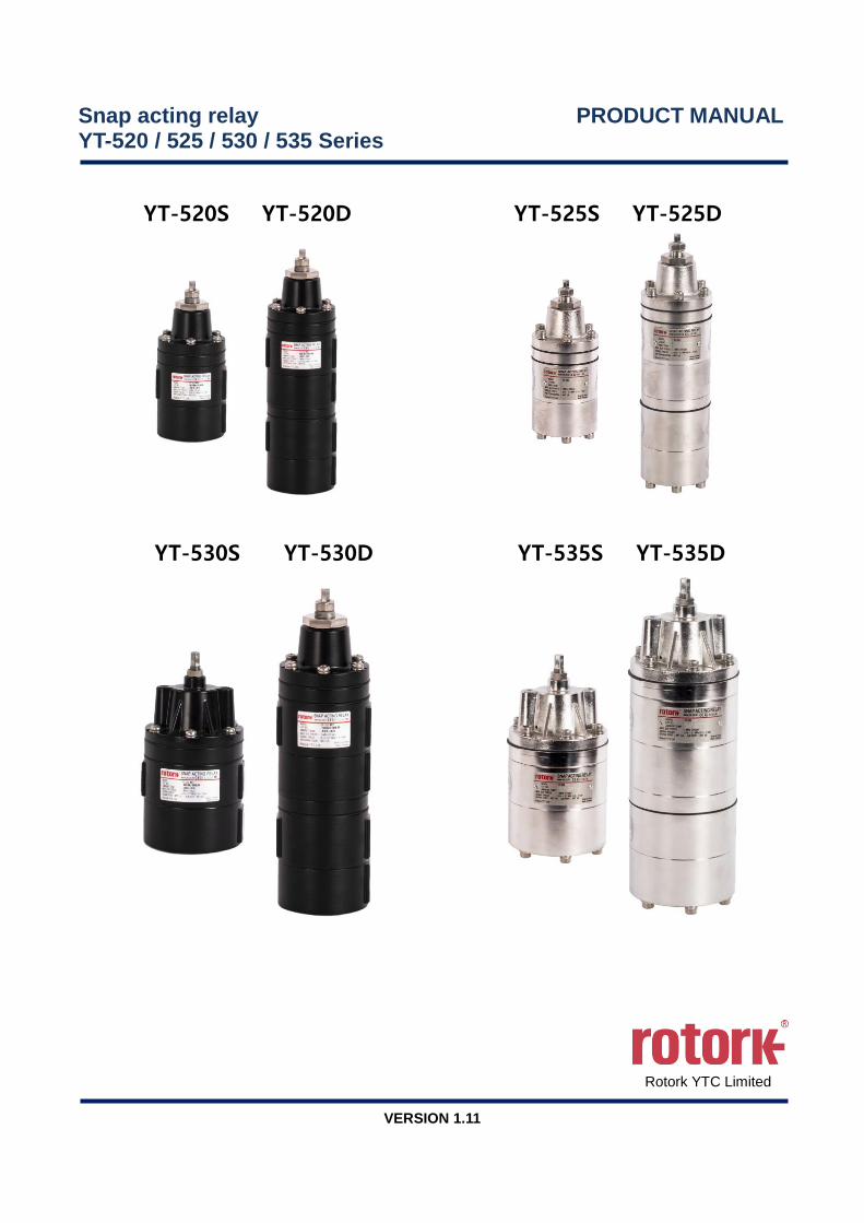
Snap acting relay PRODUCT MANUAL YT-520 / 525 / 530 / 535 Series
YT-520S YT-520D YT-525S YT-525D
YT-530S YT-530D YT-535S YT-535D
Rotork YTC Limited
VERSION 1.11

Snap acting relay YT-520 / 525 / 530 / 535 series Product Manual
Ver. 1.11 2
Contents 1 Introduction .................................................................................................................................................3
1.1 General Information for the users .........................................................................................................3
1.2 Manufacturer Warranty .........................................................................................................................3
2 Product Description ...................................................................................................................................4
2.1 General .................................................................................................................................................4
2.2 Main Features and Functions ...............................................................................................................4
2.3 Label Description ..................................................................................................................................5
2.4 Product Code ........................................................................................................................................6
2.5 Product Specification ............................................................................................................................6
2.6 Product Dimension ...............................................................................................................................7
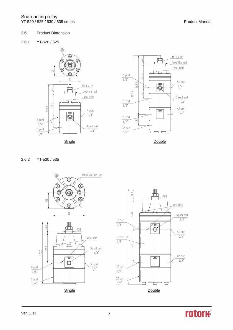
2.6.1 YT-520 / 525 .....................................................................................................................................7
2.6.2 YT-530 / 535 .....................................................................................................................................7
2.7 Operation Logic.....................................................................................................................................8
2.8 Section drawings ..................................................................................................................................9
2.8.1 YT-520 / 525 .....................................................................................................................................9
2.8.2 YT-530 / 535 .................................................................................................................................. 10
3 Installation ................................................................................................................................................. 11
3.1 Safety ................................................................................................................................................. 11
3.2 Installation .......................................................................................................................................... 12
4 Maintenance ............................................................................................................................................. 14
4.1 Replacement of Parts (Repair kit)...................................................................................................... 14
4.2 Replacing Upper diaphragm ass’y ..................................................................................................... 14
5 Trouble-Shooting ..................................................................................................................................... 15
Snap acting relay YT-520 / 525 / 530 / 535 series Product Manual
Ver. 1.11 3
1 Introduction
1.1 General Information for the users
Thank you for purchasing Rotork YTC Limited products. Each product has been fully inspected after
its production to offer you the highest quality and reliable performance. Please read the product
manual carefully prior to installing and commissioning the product.
➢ Installation, commissioning, and maintenance of the product may only be performed by trained
specialist personnel who have been authorized by the plant operator accordingly.
➢ The manual should be provided to the end-user.
➢ The manual can be altered or revised without any prior notice. Any changes in product’s
specification, design, and/or any components may not be printed immediately but until the
following revision of the manual.
➢ The manual should not be duplicated or reproduced for any purpose without prior approval from
Rotork YTC Limited Gimpo-si, South Korea.
➢ In case of any other problems that are not stated in this manual, please make immediate contact
Rotork YTC Limited.
1.2 Manufacturer Warranty
➢ For the safety, it is important to follow the instructions in the manual. Manufacturer will not be
responsible for any damages caused by user’s negligence.
➢ Any modifications or repairs to the product may only be performed if expressed in this manual.
Injuries and physical damages caused by customer’s modifying or repairing the product without
a prior consultation with Rotork YTC Limited will not be compensated. If any alterations or
modifications are necessary, please contact Rotork YTC Limited directly.
➢ Standard type with NBR rubber (ambient temperature range option 1) is subject to damage by
ozone. If you suspect that ozone may be present at the site or if supplied air is likely to contain
ozone, select a high temperature version (ambient temperature range option 2) or a low
temperature version (ambient temperature range option 3) with SILICONE rubber.
➢ The warranty period of the product is (18) months from the date of shipment unless stated
otherwise. Date of shipment can be checked by providing the LOT NO. or SERIAL NO. to us.
➢ Manufacturer warranty will not cover products that have been subjected to abuse, accidents,
alterations, modifications, tampering, negligence, misuse, faulty installation, lack of reasonable
care, repair or service in any way that is not contemplated in the documentation for the product,
or if the model or serial number has been altered, tampered with, defaced or removed; damages
that occurs in shipment, due to act of God, failure due to power surge, or cosmetic damage.
Improper or incorrectly performed maintenance will void this limited warranty.
➢ For detailed warranty information, please contact the corresponding local Rotork YTC Limited
office or main office in South Korea.
Snap acting relay YT-520 / 525 / 530 / 535 series Product Manual
Ver. 1.11 4
2 Product Description
2.1 General
Snap Acting Relay is a device that receives its main pneumatic pressure from the plant as signal
pressure and changes the direction of pneumatic flow by changing the direction of the flow path
inside the product when the signal pressure drops below the set pressure. For general use, it is
installed on the control valve, and when the main pneumatic pressure from the compressor is lower
than the required pressure due to power failure or pipe breakage, it senses the drop and flows the
pressure from the air tank which is connected to the Snap Acting Relay to the actuator of the control
valve and moves the valve to the safe position.
2.2 Main Features and Functions
➢ It can be installed using only piping without a separate bracket.
➢ Hysteresis is below 0.01 MPa.
➢ Built-in 80 mesh screen prevents foreign matter from entering and prevents malfunction.
➢ Highly corrosion-resistant polyester powder coated aluminum body or stainless steel body for
high durability in various environments.

Snap acting relay YT-520 / 525 / 530 / 535 series Product Manual
Ver. 1.11 5
2.3 Label Description
Fig. L-1: YT-520 Fig. L-2: YT-525
Fig. L-3: YT-530 Fig. L-4: YT-535
• MODEL : Indicates the model number and additional symbols.
• LOT NO. : Indicates unique lot number.
• YEAR.MONTH : Indicates manufactured year and month.
• AMBIENT TEMP. : Indicates the allowable ambient temperature.
• MAX. SUPPLY : Indicates max. supply air pressure level.
• SIGNAL PRESSURE : Indicates the signal pressure range.
• AIR CONNECTION : Indicates connection thread type.
※ Precautions
Be careful not to apply volatile solvent (hardener of instant adhesive, acetone, WD-40, etc.) to
the sticker nameplate. Printed contents may be erased.

Snap acting relay YT-520 / 525 / 530 / 535 series Product Manual
Ver. 1.11 6
2.4 Product Code
YT-520 / 525 / 530 / 535 1 2 3
1 Acting type S :
D :
Single acting
Double acting
2 Air Connection type 2 : NPT
3 Ambient Temperature
1 :
2 :
3 :
A :
-20°C ~ 70°C (-4°F ~ 158°F)
-20°C ~ 120°C (-4°F ~ 248°F)
-40°C ~ 70°C (-40°F ~ 158°F)
-50°C ~ 70°C (-58°F ~ 158°F)
2.5 Product Specification
Model YT-520 YT-525 YT-530 YT-535
Max. Supply Pressure Max. 1 MPa (10 bar)
Signal Pressure Setting
Range 0.14 ~ 0.7 MPa (1.4 ~ 7 bar)
Hysteresis Below 0.01MPa (0.1 bar)
Flow Capacity (CV) 0.9 1.8
A, B, C port Connection 1/4 NPT 3/8 NPT
Signal Connection 1/4 NPT 1/4 NPT
Ambient
Temperature
Standard -20°C ~ 70°C (-4°F ~ 158°F)
High -20°C ~ 120°C (-4°F ~ 248°F)
Low -40°C ~ 70°C (-40°F ~ 158°F)
Arctic -50°C ~ 70°C (-58°F ~ 158°F)
Housing Material Aluminum Stainless Steel
316 Aluminum
Stainless Steel
316
Weight
Single 0.71 kg (1.6 lb) 1.7 kg (3.8 lb) 1.5 kg (3.3 lb) 3.3 kg (7.3 lb)
Double 1.3 kg (2.9 lb) 3.1 kg (6.9 lb) 2.7 kg (6 lb) 5.8 kg (12.8 lb)
Tested under ambient temperature of 20°C, absolute pressure of 760mmHg, and humidity of 65%.
Please contact Rotork YTC Limited for detailed testing specification.
Snap acting relay YT-520 / 525 / 530 / 535 series Product Manual
Ver. 1.11 7
2.6 Product Dimension
2.6.1 YT-520 / 525
Single Double 2.6.2 YT-530 / 535
Single Double
Snap acting relay YT-520 / 525 / 530 / 535 series Product Manual
Ver. 1.11 8
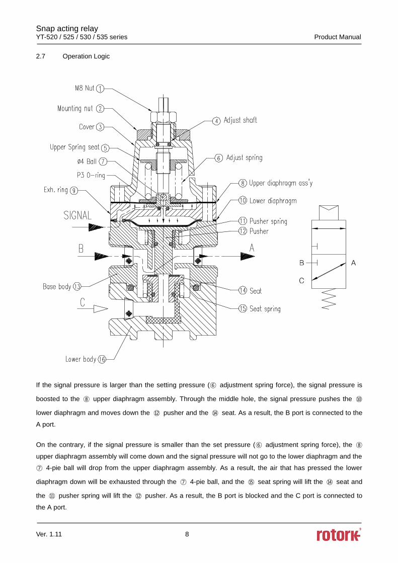
2.7 Operation Logic
If the signal pressure is larger than the setting pressure (⑥ adjustment spring force), the signal pressure is
boosted to the ⑧ upper diaphragm assembly. Through the middle hole, the signal pressure pushes the ⑩
lower diaphragm and moves down the ⑫ pusher and the ⑭ seat. As a result, the B port is connected to the
A port.
On the contrary, if the signal pressure is smaller than the set pressure (⑥ adjustment spring force), the ⑧
upper diaphragm assembly will come down and the signal pressure will not go to the lower diaphragm and the
⑦ 4-pie ball will drop from the upper diaphragm assembly. As a result, the air that has pressed the lower
diaphragm down will be exhausted through the ⑦ 4-pie ball, and the ⑮ seat spring will lift the ⑭ seat and
the ⑪ pusher spring will lift the ⑫ pusher. As a result, the B port is blocked and the C port is connected to
the A port.

Snap acting relay YT-520 / 525 / 530 / 535 series Product Manual
Ver. 1.11 9
2.8 Section drawings
2.8.1 YT-520 / 525
Single Double

Snap acting relay YT-520 / 525 / 530 / 535 series Product Manual
Ver. 1.11 10
2.8.2 YT-530 / 535
Single Double

Snap acting relay YT-520 / 525 / 530 / 535 series Product Manual
Ver. 1.11 11
3 Installation
3.1 Safety
When installing a unit, please ensure to read and follow safety instructions.
➢ Be sure to have protective equipment and comply with safety regulations.
➢ Use within specifications specified in the manual. Exceeding the specification may result in
damage to the product or accident.
➢ The supply pressure must be clean, dry air and non-corrosive gas and must be filtered.
➢ Do not let impurities or foreign materials enter the snap acting relay, especially to the signal
pressure port.
➢ Do not apply the signal pressure beyond the specified specification after piping connection. If
the signal pressure exceeds the specified specification, the diaphragm may be damaged and
the product may malfunction.
➢ When adjusting the set pressure after installation, temporarily install a pressure gauge or other
equipment that can read the signal pressure and adjust the set pressure while reading the
signal pressure. If the set pressure is adjusted without an instrument such as a pressure gauge,
the product may be damaged by exceeding the specified specification or turning the adjustment
screw too much.
➢ Be sure that the difference between setting pressure and signal pressure is over 0.1MPa.
➢ After setting the pressure, secure the nut so that the adjustment bolt does not turn.
➢ If there is any impact on the product, it may cause malfunction or failure, so be careful during
handling, installation and operation.
➢ Install the product with the adjustment bolt facing up. Otherwise, the life cycle of the product
may be shortened or moisture and foreign substance may enter into the vent hole, leading to
damaging internal parts.
Snap acting relay YT-520 / 525 / 530 / 535 series Product Manual
Ver. 1.11 12
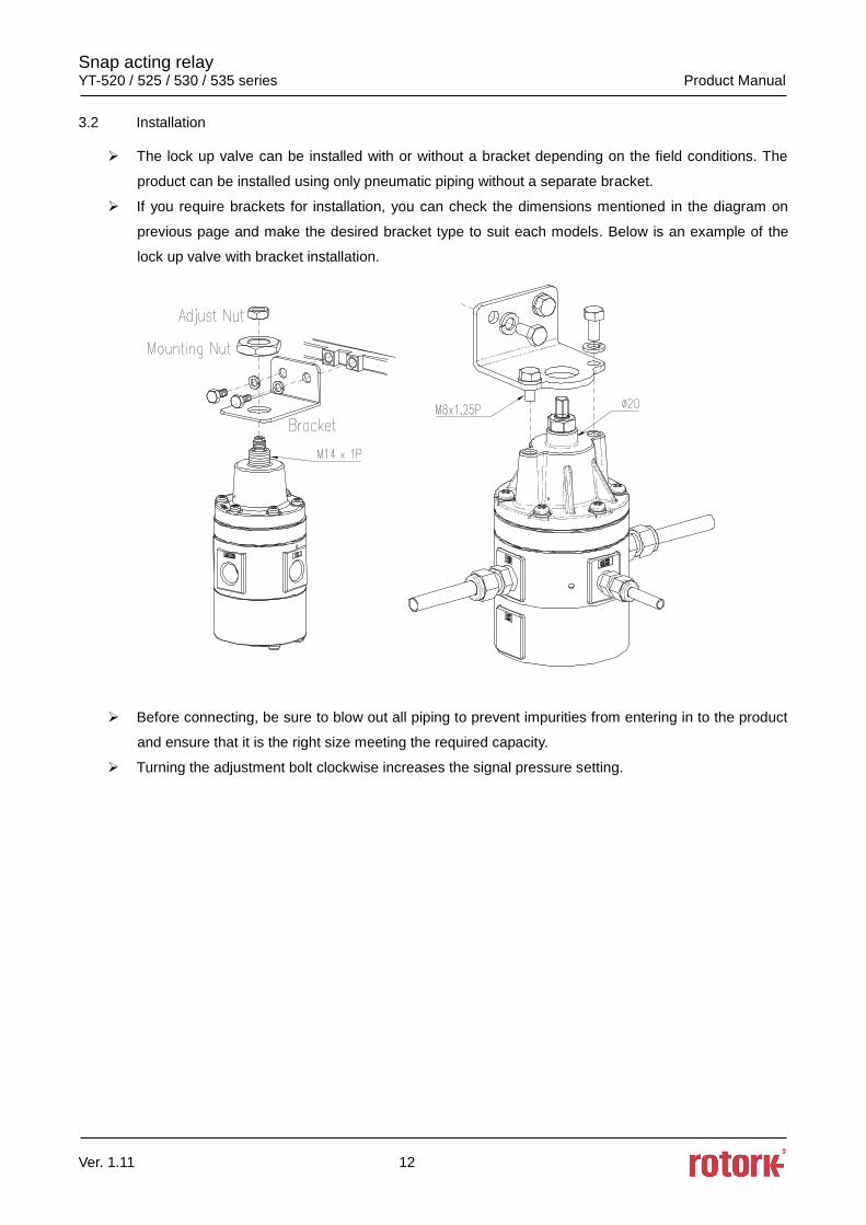
3.2 Installation
➢ The lock up valve can be installed with or without a bracket depending on the field conditions. The
product can be installed using only pneumatic piping without a separate bracket.
➢ If you require brackets for installation, you can check the dimensions mentioned in the diagram on
previous page and make the desired bracket type to suit each models. Below is an example of the
lock up valve with bracket installation.
➢ Before connecting, be sure to blow out all piping to prevent impurities from entering in to the product
and ensure that it is the right size meeting the required capacity.
➢ Turning the adjustment bolt clockwise increases the signal pressure setting.

Snap acting relay YT-520 / 525 / 530 / 535 series Product Manual
Ver. 1.11 13
3.3 Installation Example
Single
Double

Snap acting relay YT-520 / 525 / 530 / 535 series Product Manual
Ver. 1.11 14
4 Maintenance
4.1 Replacement of Parts (Repair kit)
The snap acting relay requires regular maintenance. If necessary, replace the following part.
➢ Upper diaphragm ass’y : 1 ea
4.2 Replacing Upper diaphragm ass’y
➢ When replacing the upper diaphragm ass’y, the main supply pressure to the product must be
shut down completely.
➢ Loosen the nut of the adjust bolt and turn the adjust bolt counterclockwise until it does not feel
repulsive force.
➢ Unscrew 6 bolts on spring case assembly in diagonal direction.
➢ Replace the upper diaphragm assembly with a new one and be careful not to lose the 4-pie steel
ball on the top diaphragm assembly and the O-ring (P3) on the bottom.
➢ Lock the six bolts back on the base cover. Be careful not to damage the diaphragm due to
excessive torque when tightening.
➢ Turn the adjust bolt to adjust the signal pressure setting. Then, lock the locking nut.

Snap acting relay YT-520 / 525 / 530 / 535 series Product Manual
Ver. 1.11 15
5 Trouble-Shooting
1) When the signal pressure drops below the set pressure but Snap Acting Relay does not switch the
flow
➢ Please check if the setting pressure level is correct. If the setting pressure level is extremely
high, please lower the setting pressure level. The factory default setting pressure level is 0.3
MPa
2) When the Signal pressure is higher than the set pressure but Snap Acting Relay stays in switched
condition.
➢ Please check if the setting pressure level is correct. If the setting pressure level is extremely
low, please raise the setting pressure level.
3) When the air pressure is continuously discharged from the exhaust hole of the base cover.
➢ The upper diaphragm may be damaged or foreign material may be attached to the steel ball
placed in the middle of the upper diaphragm assembly. Replace the upper diaphragm assembly
or clean any debris from the steel ball and reassemble.
4) When the air pressure is continuously discharged from the exhaust hole in the snap acting relay body.
➢ The inner rubber part may be damaged. Please contact our Customer Support Department for
repair.
Snap acting relay YT-520 / 525 / 530 / 535 series Product Manual
Ver. 1.11 16
Manufacturer: Rotork YTC Limited
Address: 81, Hwanggeum-ro, 89 Beon-gil, Yangchon-eup, Gimpo-si, Gyeonggi-do, South Korea
Postal code: 10048
Tel: +82-31-986-8545
Fax: +82-70-4170-4927
Email: [email protected]
Homepage : http://www.ytc.co.kr
Issued : 2020-02-25
Copyright © Rotork YTC Limited. All Rights Reserved.