smt. s. r. patel engineering college dabhi-unjha - 384...
TRANSCRIPT

Smt. S. R. PATEL ENGINEERING COLLEGE Dabhi-unjha - 384 170
Department of Mechanical engineering
Subject : Computer Integrated Manufacturing
Subject code: 171903
EXP
ERIM
ENTS
IN C
OM
PU
TER
INTE
GR
ATE
D M
AN
UFA
CTU
RIN
G
Experiments in Computer Integrated Manufacturing: Semester VII
Mechanical Engineering, Smt. S. R. Patel Engg. College, Dabhi
INDEX
Sr.
No. Experiment
Page
No. Date Marks Sign
1 Introduction of CIM and its importance in manufacturing
environment
1
2 Introduction of FMS 19
3 Flexibility in FMS and its measurements 41
4 Selection of FMC according to lamb technical method 50
5
Increasing of Unutilized Workstation Capacity of a
Complex FMS by Quantitative Analysis using Bottleneck
model.
57
6 Introduction of GT and part family forming using different
method 68
7 Grouping Parts & Machines By Rank Order Clustering 81
8 Study and Demonstration on Robots. 91
9 Prepare Program and carryout NC Job . 98

Computer Integrated Manufacturing: Semester VII
Mechanical Engineering, S.R. Patel Engg. College, Dabhi Page 1
Practical: - 01
AIM:-Introduction of CIM and its importance in manufacturing environment.
CIM (Definition):-
CIM means exactly what it says: computer-integrated manufacturing. It describes
integrated applications of computers in manufacturing. A number of observers have
attempted to refine its meaning:
“CIM is the integration of the total manufacturing enterprise through the use of integrated
systems and data communications coupled with new managerial philosophies that
improve organizational and personnel efficiency.” (By CASA/SME)
“CIM is nothing but a data management and networking problem.”
“computer-integrated manufacturing is contagious.”
“CIM is an amorphous beast. It will be different in every companies.”
“CIM is a management philosophy, not a turnkey computer product. It is a philosophy
crucial to the survival of most manufacturers because it provides the levels of product
design & production control & shop flexibility to compete in future domestic and
international markets.”
“CIM is an opportunity for realigning your two most fundamental resources people and
technology. CIM is a lot more than the integration of mechanical, electrical , and even
informational systems. It‟s an understanding of the new way to manage.”
CIM Hardware & CIM Software:-
CIM Hardware comprises the following:
Manufacturing equipment such as CNC machines or computerised work centres, robotic
work cells, DNC/FMS systems, VNC systems, work handling & tool handling devices,
inspection machines etc…
Computers, controllers, CAD/CAM systems, workstations/terminals, data entry
terminals, bar code readers, printers, plotters and other peripheral devices, modems,
cables, connectors etc…
CIM Software comprises computer programmes to carry out the following functions:
Management Information System
Sales
Computer Integrated Manufacturing: Semester VII
Mechanical Engineering, S.R. Patel Engg. College, Dabhi Page 2
Marketing
Finance
Database management
Modelling and Design
Analysis
Simulation
Communications
Monitoring
Production Control
Manufacturing area control
Job tracking
Inventory Control
Shop floor data collection
Order entry
Materials handling
Device drivers
Process planning
Manufacturing facilities
Work flow automation
Business process engineering
Network management
Quality management
Nature and Role of the CIM System:
Nine major elements of a CIM system are
Marketing
Product Design
Planning
Purchase
Manufacturing Engineering
Factory Automation hardware
Warehousing
Finance
Information management
Marketing: The need for a product is identified by the marketing division. The
specifications of the product, the projection of manufacturing quantities and the strategy
for marketing the product are also decided by the marketing department.

Computer Integrated Manufacturing: Semester VII
Mechanical Engineering, S.R. Patel Engg. College, Dabhi Page 3
Product Design: The design department of the company establishes the initial database
for production of a proposed product. In CIM system this is accomplished through
activities such as geometric modelling and computer aided design while considering the
product requirements and concepts generated by the creativity of the design engineer.
Planning: The planning department takes the database established by the product design
and enriches it with production data and information to produce a plan for the production
of the product.
Purchase: The purchase department is responsible for placing the purchase orders and
follows up, receive the items, arrange for inspection and supply the items to stores for
eventual supply to manufacture and assembly.
Manufacturing Engineering: Manufacturing Engineering is the activity of carrying out
the production of the product, involving further enrichment of the database with
performance data and information about the production equipment and processes.
Factory Automation hardware: Factory Automation equipment further enriches the
database with equipment and process data, resident either in the operator or the equipment
to carry out the production process.
Warehousing: Warehousing is the function involving storage and retrieval of raw
materials, components, finished goods as well as shipment of items.
Finance: Finance deals with the resources pertaining to money. Planning of investment,
working capital, cash flow control, accounting and allocation of funds are the major task
of the finance departments.
Information management: Information management is perhaps one of the crucial tasks
in CIM. This involves master production scheduling, database management,
communication, manufacturing systems integration and management information systems.
CIM technology ties together all the manufacturing and related functions in a company.
(Various Activities in CIM)
CAD, Shop data, FEM, MEM, Analysis, Drafting, Process Planning, Tool design,
Product Planning, Scheduling, Simulation, CNC, Robots, FMS, AS/RS, QC.
Marketing, Finance, Purchase, Human Resource, ERP, Shipping, Data Base, Internet
an
Machine tool, Material handling system, Computer system, Human labour FME-Finite
Element Modelling , MEM- Mechanism Modelling , ERP-Enterprise Resource Planning,
QC-Quality Control
Computer Integrated Manufacturing: Semester VII
Mechanical Engineering, S.R. Patel Engg. College, Dabhi Page 4
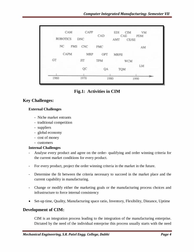
Fig.1: Activities in CIM
Key Challenges:
External Challenges
- Niche market entrants
- traditional competition
- suppliers
- global economy
- cost of money
- customers
Internal Challenges
- Analyse every product and agree on the order- qualifying and order winning criteria for
the current market conditions for every product.
- For every product, project the order winning criteria in the market in the future.
- Determine the fit between the criteria necessary to succeed in the market place and the
current capability in manufacturing.
- Change or modify either the marketing goals or the manufacturing process choices and
infrastructure to force internal consistency
Set-up time, Quality, Manufacturing space ratio, Inventory, Flexibility, Distance, Uptime
Development of CIM:
CIM is an integration process leading to the integration of the manufacturing enterprise.
Dictated by the need of the individual enterprise this process usually starts with the need

Computer Integrated Manufacturing: Semester VII
Mechanical Engineering, S.R. Patel Engg. College, Dabhi Page 5
to interchange information between the some of the so called ISLANDS OF
AUTOMATION. Flexible manufacturing cells, Automatic Storage & Retrieval Systems,
CAD/CAM based design are the examples of islands of automation.
CIM Wheel:
Fig.2: CASA/CME’S CIM Wheel-An embodiment of the concept of computer integrated
manufacturing
CASA/SME has suggested a framework, the CIM WHEEL. to elucidate the meaning of
CIM.
CIM is closed loop system whose prime inputs are product requiring concept prime
output are finished product.
CASA/SME: Computer and Automated system Association of the Society of
Manufacturing Engineers.
The CIM Wheel: It depict a central core [ Integrated System architecture] that handles
the common manufacturing data and is concern with information resources management
& communications.
The radial sectors surrounding the core (wheel hub) represents the various act ivies of
manufacturing processing design, material, processing & inspection.
Computer Integrated Manufacturing: Semester VII
Mechanical Engineering, S.R. Patel Engg. College, Dabhi Page 6
These Activities has been grouped under three categories.
Manufacturing planning & control
Product process ,&
Factory automation.
As depicted in the wheel„s inner Rim.
The outer Rim represents the upper management functions, grouped into four categories:
Strategic planning
Marketing
Manufacturing & HR management
Finance
Fig.2 shows the CIM Wheel. (CASA/SMA)
The CIM Wheel depicted in fig. is the expanded version of an earlier model.
The outer Rim was added in1985, to compile the need of including both management and
technology function with in the scope of CIM.
CIM is broad enough to en-compass all aspect of the manufacturing enterprise & its
management, including those of personnel & finance.
Strengths of CIM Wheel:
This CIM Wheel represents different resources required for the complete implementation
of the CIM.
The second Rim form out side defined the main CIM implementation required three main
functional in evolvement.
1. Manufacturing planning & control
2. Product process ,&
3. Factory automation.
The outer Rim shows the management & recourse requirement of the CIM
implementation.
It can also helpful to find out the Island requiring for the complete CIM.
Weakness of the CIM Wheel:
The main & the major weakness of the CIM Wheel is it does not Shows the way of
integration
It is also doesn‟t represent the complete connection of the different island.
We can not clarify in which sequence we have to plan for implementation of the CIM.
The existing CIM Wheel is not being time constrained or not giving articulation process
constituents or weight age for the same.

Computer Integrated Manufacturing: Semester VII
Mechanical Engineering, S.R. Patel Engg. College, Dabhi Page 7
Fig.3:The CIM Jigsaw
CIM Enterprise Wheel:
Fig.4: The New Manufacturing Enterprise Wheel Suggested by Society of
Manufacturing Engineers, Dearborn, Michigan
Computer Integrated Manufacturing: Semester VII
Mechanical Engineering, S.R. Patel Engg. College, Dabhi Page 8
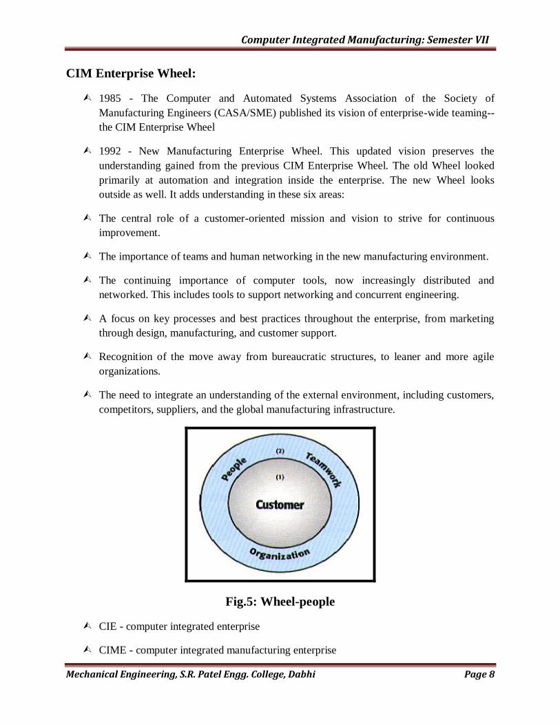
CIM Enterprise Wheel:
1985 - The Computer and Automated Systems Association of the Society of
Manufacturing Engineers (CASA/SME) published its vision of enterprise-wide teaming--
the CIM Enterprise Wheel
1992 - New Manufacturing Enterprise Wheel. This updated vision preserves the
understanding gained from the previous CIM Enterprise Wheel. The old Wheel looked
primarily at automation and integration inside the enterprise. The new Wheel looks
outside as well. It adds understanding in these six areas:
The central role of a customer-oriented mission and vision to strive for continuous
improvement.
The importance of teams and human networking in the new manufacturing environment.
The continuing importance of computer tools, now increasingly distributed and
networked. This includes tools to support networking and concurrent engineering.
A focus on key processes and best practices throughout the enterprise, from marketing
through design, manufacturing, and customer support.
Recognition of the move away from bureaucratic structures, to leaner and more agile
organizations.
The need to integrate an understanding of the external environment, including customers,
competitors, suppliers, and the global manufacturing infrastructure.
Fig.5: Wheel-people
CIE - computer integrated enterprise
CIME - computer integrated manufacturing enterprise

Computer Integrated Manufacturing: Semester VII
Mechanical Engineering, S.R. Patel Engg. College, Dabhi Page 9
CIM means many different things to many different people.
“The integration of business, engineering, manufacturing and management information
that spans company functions from marketing to product distribution.” Harrington
Originally, to integrate what had already been computerized.
shop floor processes
manufacturing engineering planning of those processes
Production planning and control of both the shop floor and the materials used.
Wheel - Six Elements:
The new Manufacturing Enterprise Wheel describes six fundamental elements for
competitive manufacturing:
The central role of the customer and evolving customer needs.
The role of people and teamwork in the organization.
The revolutionary impact of shared knowledge and systems to support people and
processes.
Key processes from product definition through manufacturing and customer
support.
Enterprise resources (inputs) and responsibilities (outputs).
Wheel - customer centered:
A customer-centered mission provides a clear direction to align activities and
empowers the work of teams in the new manufacturing enterprise.
Fig.6: Wheel - customer centered
The central role of people in the organization forms the inner circle of the Wheel. The
enterprise is only as strong as its people, organization, and culture.
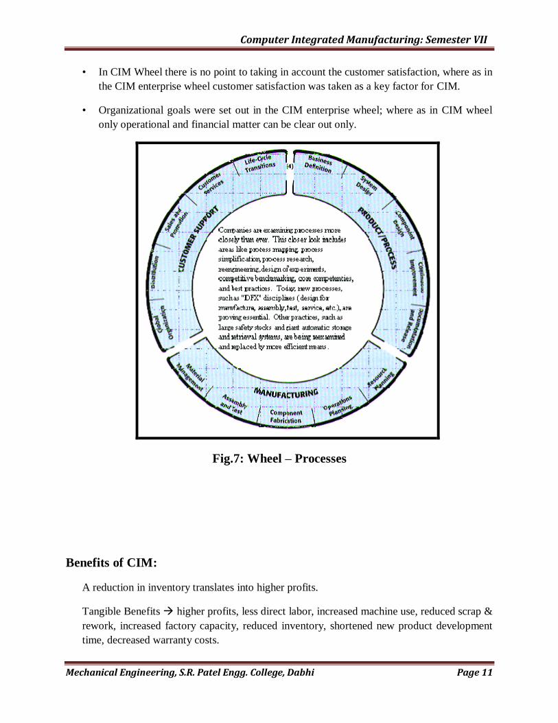
Wheel - 15 Processes:
PRODUCT/PROCESS DEFINITION:
Computer Integrated Manufacturing: Semester VII
Mechanical Engineering, S.R. Patel Engg. College, Dabhi Page 10
1) Business Definition
2) System Design
3) Component Design
4) Continuous Improvement
5) Documentation and Release
MANUFACTURING (Service)
6) Resource Planning
7) Operations Planning
8) Component Fabrication
9) Assembly and Test
10) Material Management
CUSTOMER SUPPORT:
11) Global Organization
12) Distribution
13) Sales and Promotion
14) Customer Services
15) Life-Cycle Transitions
Wheel - Manufacturing Infrastructure: Infrastructure separates top manufacturing regions and
countries from others.
• workforce
• investment
• transportation
• communication
• suppliers
• schools
• research
• government support
Similarities between both wheels:
• In middle rim both of the wheel shows the product ,processes and manufacturing
facilities requires for the CIM implementation.
• Both wheels try to explain the resources required to getting complete CIM.
• The most of the island related to manufacturing & design in both wheel are similar.
Differences between both wheels:
• The CIM Wheel more emphasis on information system, design & manufacturing &
business. Segment where as the CIM Enterprise wheel emphasis on customer satisfaction,
knowledge management, business design and business global.
• The CIM Wheel is also concentrate on the factory automation side that portion was not
included in the CIM Enterprise wheel.
Computer Integrated Manufacturing: Semester VII
Mechanical Engineering, S.R. Patel Engg. College, Dabhi Page 11
• In CIM Wheel there is no point to taking in account the customer satisfaction, where as in
the CIM enterprise wheel customer satisfaction was taken as a key factor for CIM.
• Organizational goals were set out in the CIM enterprise wheel; where as in CIM wheel
only operational and financial matter can be clear out only.
Fig.7: Wheel – Processes
Benefits of CIM:
A reduction in inventory translates into higher profits.
Tangible Benefits higher profits, less direct labor, increased machine use, reduced scrap &
rework, increased factory capacity, reduced inventory, shortened new product development
time, decreased warranty costs.

Computer Integrated Manufacturing: Semester VII
Mechanical Engineering, S.R. Patel Engg. College, Dabhi Page 12
Intangible Benefits higher employee morale, safer working environment, improved
customer image, greater scheduling flexibility, greater ease in recruiting new employees,
increased job security, more opportunities for upgrading skills.
CIM - to coordinate and organize data
functional - about organization (still important)
product - about parts
operational - plan or instructions
performance - reporting on performance
CIM - to meet competitive pressures
to reduce lead times
to reduce costs
to reduce inventory (or need for)
CIM – others: to eliminate paper
automate communication
simultaneous engineering (IPD)
Because it is possible?
To reduce communication time
CIM I & II : Computer-interfaced manufacturing & Computer integrated manufacturing
Fig.9: CIM-I & II
• Manufacturing Planning & Control
- MRPII, MRP, CRP, shop floor control, inventory Control, …
• Manufacturing Engineering
- CAD/CAM, CAPP, coding & Classification, …

Computer Integrated Manufacturing: Semester VII
Mechanical Engineering, S.R. Patel Engg. College, Dabhi Page 13
• Manufacturing Processes
- NC/CNC/DNC, FMS, robots, material handling Systems, …
• Indirect Elements:
- Sales order processing (& marketing)
- Finance & accounting
LSI/VSI CIM-1 Data interfaced management environment
PARELLEL PROCESSING CIM-2 Networked management environment
Integration in CIM:
Fig.10: Integration
Parts indistinguishable?
No, seamlessly linked is what we mean
NC/CNC Machines
Fig.11: Integration – linked
EDI - Electronic Data Interchange:
EDI : Electronic Data Interchange -
Computer Integrated Manufacturing: Semester VII
Mechanical Engineering, S.R. Patel Engg. College, Dabhi Page 14
(1) The subject of electronic data exchange and sharing generally, or
(2) Electronic data and/or document interchange format (X12), particularly in a
purchasing context.
EDIF : Electronic Data Interchange Format
A neutral file specification for the transfer of electronic CAD/CAM data.
EDIFACT : Electronic Data Interchange for Administration, Commerce & Trade
A standard for commercial transactions between (differing) computer systems of different
commercial organizations.
Although we often talk of EDI applied to exchange of technical information it is properly
used to describe commercial transactions such as the passing of invoices. Standards for
EDI exist and are widely used. UN EDIFACT is becoming the accepted standard for this
type of transaction. When technical information is exchanged between computer system
(see the item below), this is really a sub-set of technical data sharing. In these
circumstances we should use the term technical EDI, or TEDI. (Fig. 11).
*****#####*****
QUIZ:
1. Give the elements of nc machine tool system.
2. Explain the cim wheel with neat sketch.
3. Give the benefits of cim.
4. Explain impact of cim on personnel.
5. Enlist the types of computer aided process planning and explain any one of them.

Computer Integrated Manufacturing: Semester VII
Mechanical Engineering, S.R. Patel Engg. College, Dabhi Page 15
Practical:- 02
AIM:Introduction of FMS.
FMS:
FMS is an integrated approach to automating a production. The primary characteristic of
an FMS is that it is a computer-controlled manufacturing system that ties together
storage, manufacturing machines, inspection, tooling, and materials handling equipment.
The FMS is designed to be flexible so that it can manufacture a variety of products at
relatively low volumes, with minimum lead time between product changes.
A flexible manufacturing system is highly automated GT machine cell, consisting of group of processing workstation, interconnected by automated material handling and storage system and controlled by distributed computer system. The reason the FMS is called flexible is that it is capable of processing a variety of different part, systems and quantity of production.
An FMS relies on principle of group technology. No manufacturing system can be completely flexible. These are limits to the range of parts or products that can be made in an FMS.
A more appropriate term for an FMS would be flexible automated system to differentiate it from manned GT machine cell or conventional transfer line.
A Series of automatic machine tools linked to gather with an automatic material handling system, a common hierarchal digital programmed. Computer control & provision for random fabrication of parts and assemblies that falls within predetermined families.
A flexible manufacturing system îs a group of Nc machine tools that can randomly process a group of parts having automated material handling system & central computer control to dynamically balance resource utilization so that the system can adapt automatically to changes in parts production, mixes and levels of output.
A process under control to produce varieties of components or products within its stated capability and to a predetermined schedule.
A technology which will help achieve leaner factories with better response times, lower unit costs, and higher quality under an improved level of management and capital control.
Capability required for Flexibility:

Computer Integrated Manufacturing: Semester VII
Mechanical Engineering, S.R. Patel Engg. College, Dabhi Page 16
The capabilities that a manufacturing system must posses to be flexible are:
1. The ability to identify and distinguish arnong the different part and product systems processes required by system etc.
2. Quick change over & operating system
3. Quick change over of physical setup.
Fig.1:General range of application solutions based on a given set of work piece volume and
variety requirements.(Courtestesy of Kearney and Trecker Corp.)
By definition, an FMS can simultaneously process a variety of workpiceces using tooling and
fixturing made available at the right machine, at the right time, and in the right sequence. Fig-1
shows the different types of production systems and it can be seen from the figure that FMS fits
into the intermediate range of production.

Computer Integrated Manufacturing: Semester VII
Mechanical Engineering, S.R. Patel Engg. College, Dabhi Page 17
Need of FMS:
”Fig.2:Brakdown of 8760 available hours in a calendar to manufacturing
opration.
The key objective in manufacturing is to get the right raw materials or to the right machines at the
right time.
Examples indicate the underutilization of equipment and gross infficiencies existing in a vast
majority of manu facturing industries.The common day to day disturbances within overall
manufacturing process consisting of:
1. priority changes
2. Eng. Design changes
3. Tooling diffulties
4. Machine brackdowns
5. processing problems
6. Lost, misplacede, and scrapped parts
7. vendor lateness
What is needed in today‟s competitive environment, regrdless of what products a particular
company makes. This implies that:
1. There should be minimum dealy between order placement and order delivery.
2. Quality and reliability should be high.
3. operating costs should be perdictable and under control.
Computer Integrated Manufacturing: Semester VII
Mechanical Engineering, S.R. Patel Engg. College, Dabhi Page 18
4. Replacement parts should be available and accessible on a quick turnaround basis.
Objectives of FMS are:
1. Improve operational control through:
a) Reduction in the number of uncontrollable variables
b) Providing tools to recognize and rect quickly to deviations in the manufacturing plan
c) Reducing dependence on human communication
2. Reduce direct labour through:
a) Removing operators from the machining site
b) Eliminnating dependence on highly skilled machinists
c) Providing a catalyst to introduce and support unattended orlightly attended machine
operation
3. Improve short-run reponsiveness consisting of:
a) Engg. Changes
b) Processing changes
c) Machine downtime or unavailability
d) Cutting tool failure
e) Late material delivery
4. Improve long-run accommodations through quicker and easier assimilation of:
a) changing product volumes
b) New product additions and Introductions
c) Different part mixes
5. Increase machine utilization by:
a) Eliminating machine setup
b) Utilizing automated features to replace manual intervention
c) Providing quick transfer devices to keep machines in the cutting cycle
6. Reduce inventory by:
a) Reducing lot sizes
b) Improving inventory turnovers
c) Providing the plannig tools for just-in-time manufacturing
Areas of Applications of FMS:
The FMS is applicable in other manufacturing &machining:
Assembly of equipments
Semiconductor componet manufacturing
Plastic injection moulding
Sheet metal fabrication
Welding
Textile machinery manufacture
Such systems have proved to be practical and economical for applications with the following
characteristics:
Families of parts with similar geometric features for require similar types of
equipment and processes

Computer Integrated Manufacturing: Semester VII
Mechanical Engineering, S.R. Patel Engg. College, Dabhi Page 19
A moderate number of tools and processes steps
Moderate precision requirements
Types of FMS: FMS has been classified in several ways. Some of these
classification are still valid but the discussion in this book is restricted to basic types.
FMS can be distinguished accordingly to the kinds of operation they perform.
1. Processing operation.
2. Assembly operation.
Two other ways to classify FMS are by;
1. No of machines e.g. single m/c cell, flexible manufacturing cell or flexible manufacturing
system.
2. Level of flexibility e.g. dedicated FMS or random order FMS.
FMS’s Types:
a) FMC-Flexible Manufacturing Cell:The simplest,hence most flexible types of FMS is
FMC. It consists of one or more CNC machine tools, general purpose or of special design
interfaced with automated material handling and tool changers.
b) FTC- Flexible Turning Cell: One of the most important advantages of CNC machines is
their flixibility. The meaning of flexibility in this particular context is that these work
centres enable the production of components in short batches.
c) FTL- Flexible Transfer Line: Flexible transfer lines are intended for high volume
production. A part in ahigh volum production may have to undergo large number of
operations.
d) FMS-Flexible Machining Systems: FMS consist of several flexible automated machine
tools of the universal or special type which are flexibly interlinked by an automatic
workpiece flow system so that different workpieces can be machined with the same
machine configuration.This means that a FMS will be able to respond quickly to
changing market and customer demands.
Types of FMS: The basic classification of FMS is according to the level of flexibility
designed into the system. This method of classification can be applied to systems with any
number of workstations, but its application seems most common with FMCs and FMSs. Two
categories are distinguished here:
Dedicated FMS
Random-order FMS

Computer Integrated Manufacturing: Semester VII
Mechanical Engineering, S.R. Patel Engg. College, Dabhi Page 20
Fig. 3 Comparison of dedicated and random-order FMS types
Dedicated FMS:
A dedicated FMS is designed to produce a limited variety of part styles, and the complete
universe of parts to be made on the system is known in advanced. The term Special
manufacturing System has also been used in reference to this FMS type. The part family is likely
to be based on product commonality rather than geometric similarity. The product design is
considered stable, and so the system can be designed with a certain amount of process
specialization to make the operations more efficient. Instead of using general-purpose machines,
the machines can be designed for the specific processes required to make the limited part family,
thus increasing the production rate of the system. In some instances, the machine sequence may
be identical or nearly identical for all parts produced, and so a transfer line may be appropriate,
in which the workstations process the necessary flexibility to process the different parts in the
mix. Indeed, the term flexible transfer line is sometimes used for this case. The dedicated FMS is
less flexible but more capable of higher production rate.
Random-order FMS:
A random-order FMS is more appropriate when the part family is large, there are substantial
variations in part configurations, there will be new part designs introduced into the system and
engineering changes in parts currently produced, and the production schedule is subject to
change from day-to-day. To accommodate these variations, the random-order FMS must be more
flexible than the dedicated FMS. It is equipped with general-purpose machines to deal with the
variations in product and is capable of processing parts in various sequences (random-order). A
more sophisticated computer control system is required for this FMS type. The random-order
FMS is more flexible but at the price of lower production rates.
Computer Integrated Manufacturing: Semester VII
Mechanical Engineering, S.R. Patel Engg. College, Dabhi Page 21
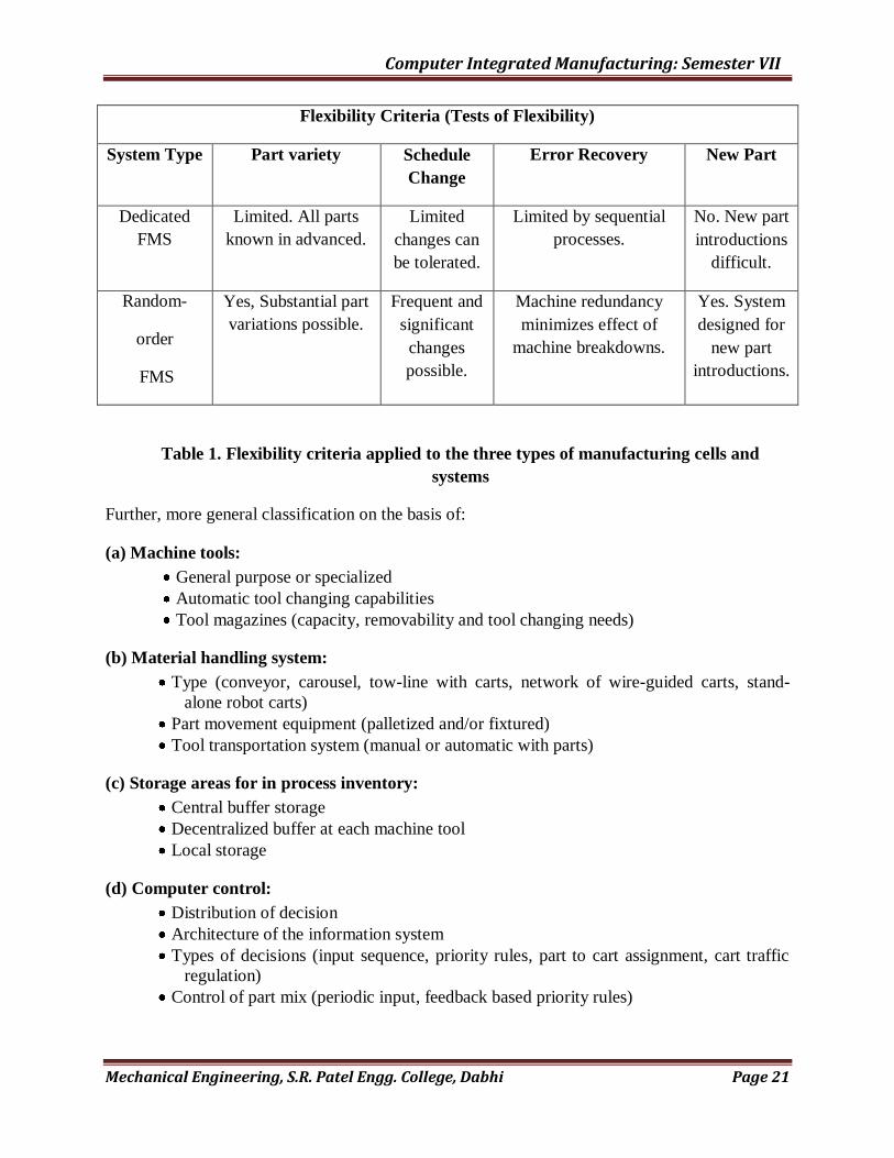
Flexibility Criteria (Tests of Flexibility)
System Type Part variety Schedule
Change
Error Recovery New Part
Dedicated
FMS
Limited. All parts
known in advanced.
Limited
changes can
be tolerated.
Limited by sequential
processes.
No. New part
introductions
difficult.
Random-
order
FMS
Yes, Substantial part
variations possible.
Frequent and
significant
changes
possible.
Machine redundancy
minimizes effect of
machine breakdowns.
Yes. System
designed for
new part
introductions.
Table 1. Flexibility criteria applied to the three types of manufacturing cells and
systems
Further, more general classification on the basis of:
(a) Machine tools:
General purpose or specialized
Automatic tool changing capabilities
Tool magazines (capacity, removability and tool changing needs)
(b) Material handling system:
Type (conveyor, carousel, tow-line with carts, network of wire-guided carts, stand-
alone robot carts)
Part movement equipment (palletized and/or fixtured)
Tool transportation system (manual or automatic with parts)
(c) Storage areas for in process inventory:
Central buffer storage
Decentralized buffer at each machine tool
Local storage
(d) Computer control:
Distribution of decision
Architecture of the information system
Types of decisions (input sequence, priority rules, part to cart assignment, cart traffic
regulation)
Control of part mix (periodic input, feedback based priority rules)

Computer Integrated Manufacturing: Semester VII
Mechanical Engineering, S.R. Patel Engg. College, Dabhi Page 22
FMS compared to other types of manufacturing approaches:
(Types of FMS Continue….)
Fig. 4 Types of Production Systems
Where,
GPM – General Purpose Machine tools
CNC – Computer Numerically Control
FMC – Flexible Manufacturing Cells
FMS – Flexible Manufacturing Systems
SPM – Special Purpose Machine tools
FTL – Flexible Transfer Line

Computer Integrated Manufacturing: Semester VII
Mechanical Engineering, S.R. Patel Engg. College, Dabhi Page 23
General Purpose Machine tools (GPM):
One-off and low volumes of production are normally carried out by conventional general
purpose machine tools. When the number of parts in a production run is more it is called batch
production. A batch production shop is best suited for very small quantities of many different
types of parts. The very nature of production makes the operation of a job shop less efficient than
an automated production line. Since the job shop must be provided the greatest degree of
flexibility, most of its operations are manual.
Computer Numerically Control (CNC):
Computer Numerically Control (CNC) machine tools paves the way for introducing flexible
automation on the shop floor. The technology of computer numerical control is today applied to
a large spectrum of material processing equipment. During the last decade, CNC technology has
improved tremendously. The clear graphics enable tool path and process simulation prior to
actual machining. With the incorporation of 32-bit controls, modern CNC systems handles large
amounts of information faster. Some of the benefits of 32-bit controls in CNC are in the areas of
sculptured shapes, sophisticated internal commands, faster editing and conversational
programming, new machine features, and more. CNC machine tools provide higher variety of
products compared to other types of production systems excepting GPM. Product volume of
CNC is comparatively higher than that of the GPM.
Flexible Machining Cells (FMC): (Type I FMS)
The simplest, hence most flexible type of FMS is a flexible machining cell. It consists of one or
more CNC machine tools, general purpose or of special designed interfaced with automated
material handling and tool changers. FMC‟s are capable of automatically machining a wide
range of different work pieces. They are usually employed in one off and small batch production
as independent machining centers, but are frequently the starting point for FMS.
Fig. 5 Flexible Manufacturing Cell

Computer Integrated Manufacturing: Semester VII
Mechanical Engineering, S.R. Patel Engg. College, Dabhi Page 24
Fig. 6 Flexible manufacturing cell layout
A turning centre fitted with a gantry loading and unloading system and pallets for storing work
pieces and finished parts is a typical flexible turning cell. If the turning centre is incorporated
with post process metrology equipment like Renishaw probes or inductive measuring equipment
for automatic offset correction, the efficiency of the system improves. Automatic tool changes,
tool magazines, block tooling, automatic tool offset measurement, automatic chuck change and
chuck jaw change etc. help to make the cell to be more productive.
One or two horizontal machining centers with modular fixturing, multiple pallets, advanced tool
management system, automatic tool changer, automatic head changer or automatic magazine
changer, robots or other material handling systems to facilitate access of the jobs to the machine
also constitute a flexible machining cell.
An FMC also comprise a turning centre, machining centre and pick and place robots or other
material handling systems. Fig. 5 shows flexible manufacturing cell. Fig.6 indicates the flexible
manufacturing cell layout. This consists of a CNC lathe, a machining centre, a small automatic
storage and retrieval system, two robots for loading and unloading the machines and a small rail
guided vehicle to carry the component from one machine tool to another. The system is
controlled by a PLC and a couple of personal computer.
Computer Integrated Manufacturing: Semester VII
Mechanical Engineering, S.R. Patel Engg. College, Dabhi Page 25
Flexible Machining System (FMS): (Type II FMS)
A large portion of the manufacturing industry involves the intermediate level of batch operations
that lead themselves to the FMS approach. FMS thus basically attempts to efficiently automate
batch manufacturing operations. They are an alternative that fits in between the manual job shop
and hard automation. FMS is best suited for applications that involve an intermediate level of
flexibility and low or medium quantities.
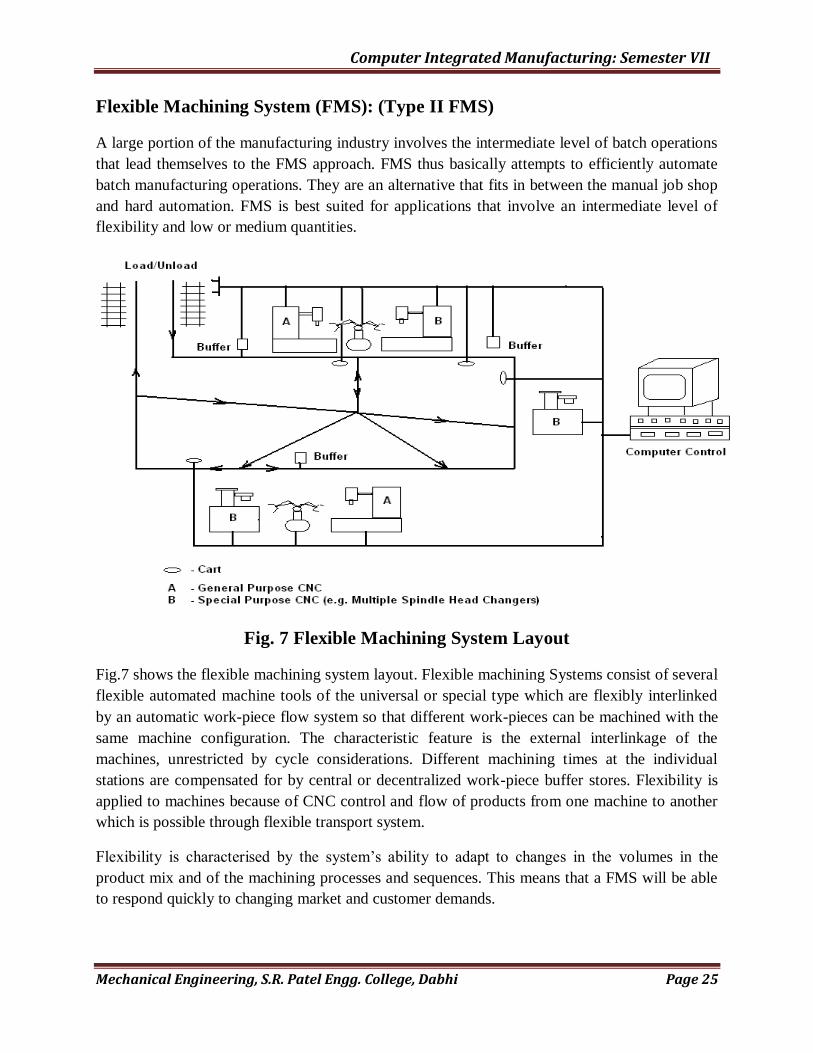
Fig. 7 Flexible Machining System Layout
Fig.7 shows the flexible machining system layout. Flexible machining Systems consist of several
flexible automated machine tools of the universal or special type which are flexibly interlinked
by an automatic work-piece flow system so that different work-pieces can be machined with the
same machine configuration. The characteristic feature is the external interlinkage of the
machines, unrestricted by cycle considerations. Different machining times at the individual
stations are compensated for by central or decentralized work-piece buffer stores. Flexibility is
applied to machines because of CNC control and flow of products from one machine to another
which is possible through flexible transport system.
Flexibility is characterised by the system‟s ability to adapt to changes in the volumes in the
product mix and of the machining processes and sequences. This means that a FMS will be able
to respond quickly to changing market and customer demands.

Computer Integrated Manufacturing: Semester VII
Mechanical Engineering, S.R. Patel Engg. College, Dabhi Page 26
A typical FMS layout is illustrated in fig. 8. Study the figure until you locate all the elements in
the FMS. The FMS shown in fig.8 is designated to produce a family of machined metal parts that
can be manufactured with three-axis vertical machining centers. Five machining centers are
required to meet the production demands; locate them in the figure. Raw material for the parts is
delivered to the automatic work changers (number 5 in the fig.) and is located onto pallets or
fixtures that will hold the material for one or more milling operations. Frequently, a partially
finished part will be removed from one fixture and placed on another in a different orientation
for additional machining. The pallets or fixtures are delivered to the correct machining center
cell by the computer-controlled cart or automatic guided vehicle (AGV). The vehicles have no
person on board for navigation and use a current-carrying wire embedded into the floor and
electronics on the cart for path, direction, and speed control.

Computer Integrated Manufacturing: Semester VII
Mechanical Engineering, S.R. Patel Engg. College, Dabhi Page 27
(1) Five Milacron 5-axis T-30 CNC machining Centers, 90 tools each.
(2) Five tool interchange stations, one per machine, accepting tool delivery via chart
(3) Three computer-controlled carts, with wire-guided path
(4) Cart maintenance station
(5) Two automatic work-changers, 10 pallets each, with dual load/unload positions with 90º tilt,
360º rotation.
(6) Two material review stands, for on demand part inspection.
(7) Inspection module, with LK Tool Co. Metre Four Micro-vector horizontal arm coordinate
measuring machine.
(8) Automatic part washing station
(9) Toll chain load/unload, tool gage, and calibration gage stands
(10) Elevated computer room, with DEC VAX 8200 central computer
(11) Centralized chip/coolant collection/recovery system, with dual flume
--------------------- Flume path
The material handling AGVs are also used to deliver tools from the setup and calibration area (9
in the fig.) to the tool interchange stations (2) in the fig.). From the tool interchange stations,
tools are changed automatically on the machining centers to match the requirements of the parts
to be produced. Finished parts still mounted to the pallets are delivered by the AGV system to
the parts washing station (8 in the fig.) prior to inspection and shipping. To track the quality of
finished parts, the AGV delivers machined parts to the coordinate measuring machine (7 in the
fig.) for automatic inspection or to the manual inspection stations (6 in the fig.). A centralized
chip and coolant recovery system collects metal removed in machining and filters the cutting
fluid used in the cells. The cells in the FMS are under area computer control from a central
computer (10 in the fig.).
Special Purpose Machine tools (SPM):
Special purpose machine tools are made for specific applications. Special types of parts or
components are made on them. In which required operations and sequence of operations are
predefined. These are also computer controlled. This type of machined are specially designed for
particular type of product, which is not possible to make on other general purpose machines. In
this type of production system the variety of product is less but the volume of product is higher.

Computer Integrated Manufacturing: Semester VII
Mechanical Engineering, S.R. Patel Engg. College, Dabhi Page 28
Flexible Transfer Line (FTL): (Type III FMS)
Flexible Transfer Lines are intended for high volume production. A part in a high volume
production may have to undergo large number of operations. Each operation is assigned to and
performed on only one machine. This results in a fixed route for each part through the system.
The material handling system is usually a pallet or carousel or conveyor. In addition to general
purpose machines, it can consist of SPM‟s , robots and some dedicated equipment. Scheduling to
balance the machine loads is easier. Unlike conventional transfer lines, a number of different
work-pieces can be manufactured on the FTL. The resetting procedure is largely automated.
Flexible Transfer Multi-line: (Type IV FMS)
In this type of FMS, multiple flexible transfer lines (type III FMS) are interconnected. This type
of FMS having the following type of characteristics:
Less process flexibility
Increased routing flexibility
Achieve best of type II and type III
Flexibility is increases form type III FMS to type II FMS
Type III FMS is generally used in U. S. A. and type II FMS is generally used in Japan.
FMS Components:
Work station:
The processing or assembly equipment used in an FMS depends on type of work
accomplished by the system.
a) Load/unload station: it is the physical interface between the FMS and rest of the factory. Raw
work parts enter the system at a point and finished part exit the system from here.
b) Machhing system: The predominant machining stations in the FMS are CNC machine tools.
c) Other processing station: the FMS concept has been applied to other processing operations.
d) Assembly: Some FMS are designed to perform assembly operation using variable
programmed robots especially in electronics components factory.
e) Other station and equipments: Here we mean machines that need not necessarily do
convenţional manufacturing like material removal; assembly etc, and instead deal with other
thing,s like possibly on-line testing; barcode reading and stamping etc. Other stations at which
the FMS can be incorporate are inspection, measurement, cleaning.
Material Handlinq and storage system:
These are the support systems of an FMS, which can be cleverly used to speed up
improve productivity of the system.
They must do following functions:
Random independent movemenî of work parts between workstations.
Handle a variety of work part configurations.
Temporary storage.
Convenient access for loading & unloading work parts.
Compatible with computer control.

Computer Integrated Manufacturing: Semester VII
Mechanical Engineering, S.R. Patel Engg. College, Dabhi Page 29
Material handling Equipment;
The types of material handling system used to transfer parts between stations in an FMS include
variety of material transfer equipments and robots. The m/t handling function in an FMS is often
shared between two systems.
(1) A primary handling system.
(2) Secondary handling system.
Difference between cell & FMS:
CELL FMS
Low Flexibility High Flexibility
Small stored part program inventory and accessibility
Large stored part program inventroy and accessibility
Limited on-line computing power and decision-making software
High on-line computing power and decision-making software
Low to moderate equipment and resource costs High equipment and resource costs
Limited flexibility and variety of parts produced
High flexibility and variety of parts produced
Low to medium preparation and implementation requirements
High preparation and implementation requirements
Benefits narrow but easily identified and quantified
Benefits broad but hard to identify and quantify
Moderate justification complexity and difficulty with mid-management approval required
Difficult and complex justification process with high-level approval required
Moderate level of management commitment and support required
High level of management commitment and support required
Low staffing and training impact High starting and training impact
Moderate effect on other internal operations and organizations
High effect on other internal operations and organizations
Short planning to implementation cycle Long planning to implementation cycle
Low to moderate risk and complexity,minimal facility changes
High risk and complexity, many facility changes or new facility required
Quick and practical learning curve and Lenthy and involveed learningcurve and
Computer Integrated Manufacturing: Semester VII
Mechanical Engineering, S.R. Patel Engg. College, Dabhi Page 30
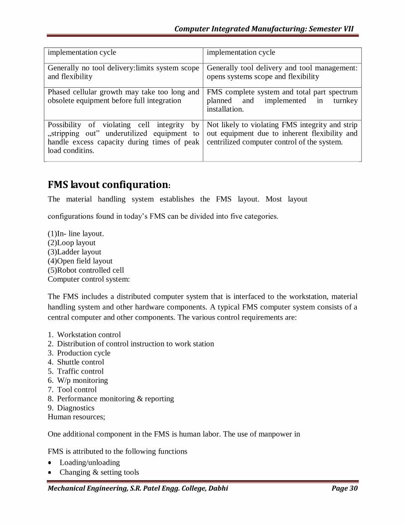
implementation cycle implementation cycle
Generally no tool delivery:limits system scope and flexibility
Generally tool delivery and tool management: opens systems scope and flexibility
Phased cellular growth may take too long and obsolete equipment before full integration
FMS complete system and total part spectrum planned and implemented in turnkey installation.
Possibility of violating cell integrity by „stripping out” underutilized equipment to handle excess capacity during times of peak load conditins.
Not likely to violating FMS integrity and strip out equipment due to inherent flexibility and centrilized computer control of the system.
FMS lavout confiquration:
The material handling system establishes the FMS layout. Most layout
configurations found in today‟s FMS can be divided into five categories.
(1) In- line layout.
(2) Loop layout
(3) Ladder layout
(4) Open field layout
(5) Robot controlled cell Computer control system:
The FMS includes a distributed computer system that is interfaced to the workstation, material
handling system and other hardware components. A typical FMS computer system consists of a
central computer and other components. The various control requirements are:
1. Workstation control
2. Distribution of control instruction to work station
3. Production cycle
4. Shuttle control
5. Traffic control
6. W/p monitoring
7. Tool control
8. Performance monitoring & reporting
9. Diagnostics Human resources;
One additional component in the FMS is human labor. The use of manpower in
FMS is attributed to the following functions
Loading/unloading
Changing & setting tools

Computer Integrated Manufacturing: Semester VII
Mechanical Engineering, S.R. Patel Engg. College, Dabhi Page 31
Maintenance & repair
NC part programming
Overall management of system
FMS Benefits:
A number of benefits expected in successful FMS application.
Increase machine utilization.
Fewer machine required.
Less factory floor space required.
Lower manufacturing lead limes.
Reduced inventory requirements.
Reduced direct labor requirements & higher productivity.
so for high productivity for all batch sizes, large or small
shorter throughput times
lower storage costs
reduced labour if not altogether avoiding labour
reduced handling
flexible production system to incorporate product changes
at short notice to meet customer‟s specific requirements.
tunity for unattended production
Quiz:
1 Define Flexible Manufacturing System.
2 Give The Objectives Of Fms.
3 Give Benefits Of Cim.
4 Give The Difference Between Fms And Fmc
5 Explain Random Fms And Dedicated Fms
6. Enlist The Fms Layout And Explain Any One Of Them
7. list types of automobile guided vehicles and explain any one of them
Computer Integrated Manufacturing: Semester VII
Mechanical Engineering, S.R. Patel Engg. College, Dabhi Page 32
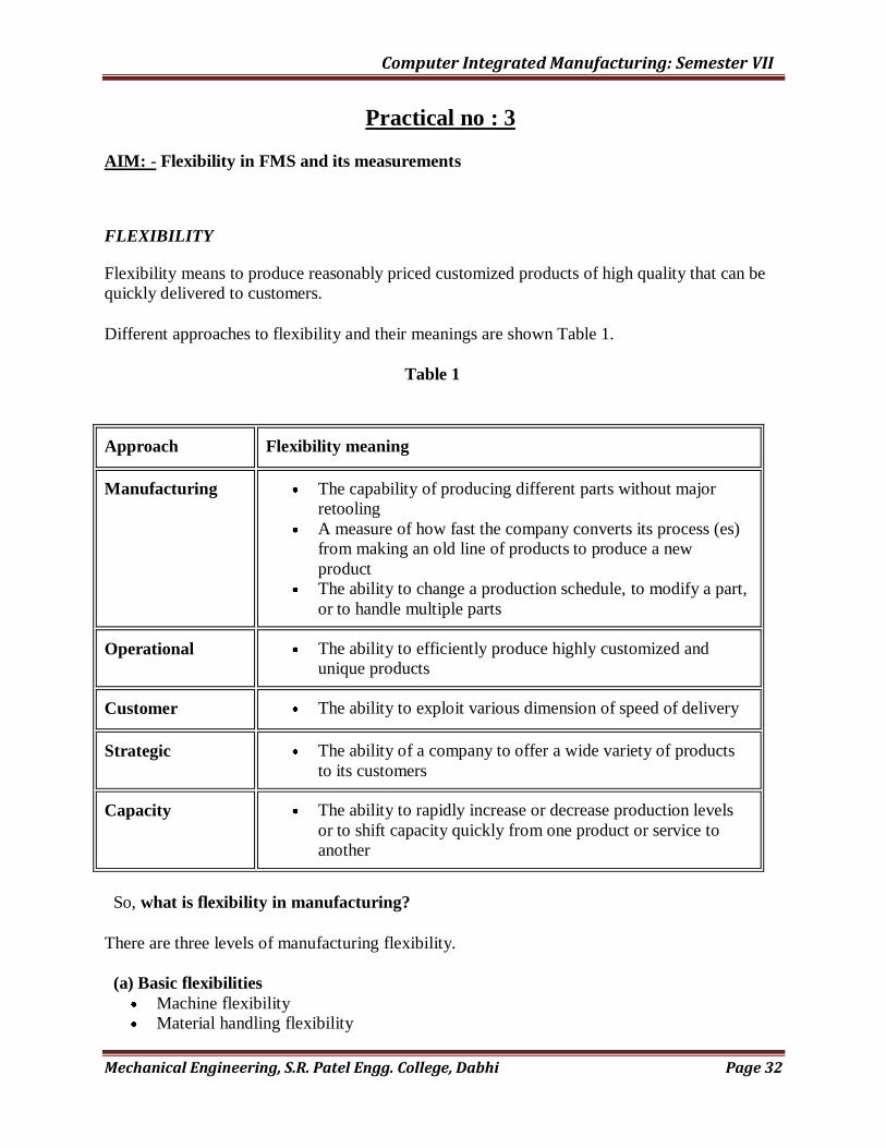
Practical no : 3
AIM: - Flexibility in FMS and its measurements
FLEXIBILITY
Flexibility means to produce reasonably priced customized products of high quality that can be
quickly delivered to customers.
Different approaches to flexibility and their meanings are shown Table 1.
Table 1
Approach Flexibility meaning
Manufacturing
The capability of producing different parts without major
retooling
A measure of how fast the company converts its process (es)
from making an old line of products to produce a new
product
The ability to change a production schedule, to modify a part,
or to handle multiple parts
Operational The ability to efficiently produce highly customized and
unique products
Customer The ability to exploit various dimension of speed of delivery
Strategic The ability of a company to offer a wide variety of products
to its customers
Capacity The ability to rapidly increase or decrease production levels
or to shift capacity quickly from one product or service to
another
So, what is flexibility in manufacturing?
There are three levels of manufacturing flexibility.
(a) Basic flexibilities
Machine flexibility
Material handling flexibility

Computer Integrated Manufacturing: Semester VII
Mechanical Engineering, S.R. Patel Engg. College, Dabhi Page 33
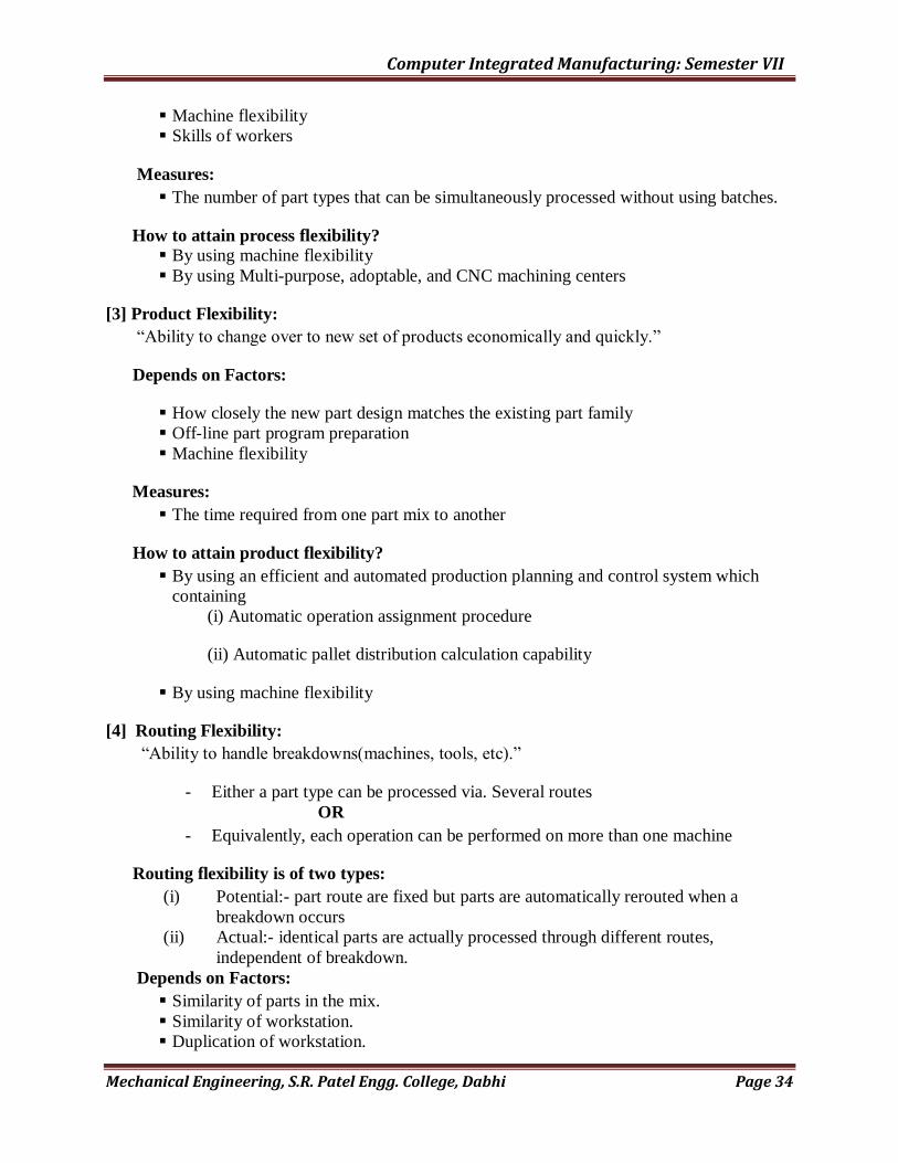
Operation flexibility
(b) System flexibilities
Volume flexibility
Expansion flexibility
Routing flexibility
Process flexibility
Product flexibility
(c) Aggregate flexibilities
Program flexibility
Production flexibility
Market flexibility
FLEXIBILITY IN FMS
[1] Machine Flexibility:
“Ease of making change required to produce a given set of part type.”
Depends on Factors:
Setup or change over time.
Ease of machine reprogramming ( ease with which part program can be downloaded
to machine).
Tool storage capacity of machines.
Skill and versatility of workers in the system.
Measures:
Time to replace worn-out or broken cutting tools.
Time to change tools in a tool magazine.
Time to assemble or mount the new fixtures.
Machine tool setup time
- Tool preparation
- Part positioning and releasing
- NC part program change over
How to attain machine flexibility?
By using sophisticated tool-loading and part loading devices(technological progress)
Minimize tool changes (proper operation assignment)
Bring the part and required tool together to the machine (technological capability)
[2] Process Flexibility:
“Ability to produce a given set of part types in several ways”
Depends on Factors:
Computer Integrated Manufacturing: Semester VII
Mechanical Engineering, S.R. Patel Engg. College, Dabhi Page 34
Machine flexibility
Skills of workers
Measures:
The number of part types that can be simultaneously processed without using batches.
How to attain process flexibility? By using machine flexibility
By using Multi-purpose, adoptable, and CNC machining centers
[3] Product Flexibility:
“Ability to change over to new set of products economically and quickly.”
Depends on Factors:
How closely the new part design matches the existing part family
Off-line part program preparation
Machine flexibility
Measures:
The time required from one part mix to another
How to attain product flexibility?
By using an efficient and automated production planning and control system which
containing
(i) Automatic operation assignment procedure
(ii) Automatic pallet distribution calculation capability
By using machine flexibility
[4] Routing Flexibility:
“Ability to handle breakdowns(machines, tools, etc).”
- Either a part type can be processed via. Several routes
OR
- Equivalently, each operation can be performed on more than one machine
Routing flexibility is of two types:
(i) Potential:- part route are fixed but parts are automatically rerouted when a
breakdown occurs
(ii) Actual:- identical parts are actually processed through different routes,
independent of breakdown.
Depends on Factors:
Similarity of parts in the mix.
Similarity of workstation.
Duplication of workstation.
Computer Integrated Manufacturing: Semester VII
Mechanical Engineering, S.R. Patel Engg. College, Dabhi Page 35
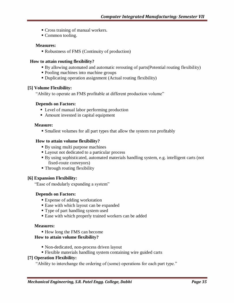
Cross training of manual workers.
Common tooling.
Measures:
Robustness of FMS (Continuity of production)
How to attain routing flexibility?
By allowing automated and automatic rerouting of parts(Potential routing flexibility)
Pooling machines into machine groups
Duplicating operation assignment (Actual routing flexibility)
[5] Volume Flexibility:
“Ability to operate an FMS profitable at different production volume”
Depends on Factors:
Level of manual labor performing production
Amount invested in capital equipment
Measure:
Smallest volumes for all part types that allow the system run profitably
How to attain volume flexibility?
By using multi purpose machines
Layout not dedicated to a particular process
By using sophisticated, automated materials handling system, e.g. intelligent carts (not
fixed-route conveyors)
Through routing flexibility
[6] Expansion Flexibility:
“Ease of modularly expanding a system”
Depends on Factors:
Expense of adding workstation
Ease with which layout can be expanded
Type of part handling system used
Ease with which properly trained workers can be added
Measures:
How long the FMS can become
How to attain volume flexibility?
Non-dedicated, non-process driven layout
Flexible materials handling system containing wire guided carts
[7] Operation Flexibility:
“Ability to interchange the ordering of (some) operations for each part type.”

Computer Integrated Manufacturing: Semester VII
Mechanical Engineering, S.R. Patel Engg. College, Dabhi Page 36
Depends on Factors:
Machine flexibility
Interchangeability of operation
Sequence of operation
Measures:
Ability and extent of not pre-determining the order of all operations, each on a
particular machine (type)
How to attain volume flexibility?
Design a decision system to make decision in real-time determining the „next‟
operation and the „next‟ machine, depending on the system state (idle, busy, bottleneck)
of various elements of FMS
Through machine flexibility
[8] Production Flexibility:
“The universe of part types that the FMS can produce”
Depends on Factors:
Machine flexibility of individual station
Range of machine flexibilities of all stations in the system
Measures:
Level of existing technology
How to attain volume flexibility?
Increase the level of technology
Increase the versatility of the machine tools
All previous flexibilities
QUIZ:
1. Define Flexibility. Explain Process Flexibility, Machine Flexibility, Product
Flexibility, Production Flexibility, Routine Flexibility, expansion flexibility
2 Explain As/Rs System with Neat Sketch.

Computer Integrated Manufacturing: Semester VII
Mechanical Engineering, S.R. Patel Engg. College, Dabhi Page 37
Practical:- 04
Aim:-Selection of FMC according to lambtechnicon method
According to Lamb Technicon, Eight factors contributes to flexibility
(1) Setup : - Ease and short duration changeover of tools, fixtures, programs, and other
issues affected by the changeover between parts.
(2) Process : - The ability to produce part in more than one way; also the mix of part the
system can cope with.
(3) Convertibility : - The ability to change the system to handle new parts that may be similar or
different.
(4) Routing : - The ability to continue producing in the event of breakdowns.
(5) Volume : - The ability to match market volume demands profitably.
(6) Expandability : - The ability to expand the facilities and cost-effectively.
(7) Operation : - The ability to shift the order of operation.
(8) Production : - The range of parts that can be produced.
The flexibility points are obtained by multiplying the weighting for each criterion with the score and
adding the result .The throughputs and capital costs for the candidate FMCs (or other flexible equipment)
are compared with their flexibility points Usually, the ratio between the capital cost and throughput is
considered .the FMC(or flexible equipment ) with smallest ratio and an acceptable value of flexibility
points is selected.
Computer Integrated Manufacturing: Semester VII
Mechanical Engineering, S.R. Patel Engg. College, Dabhi Page 38
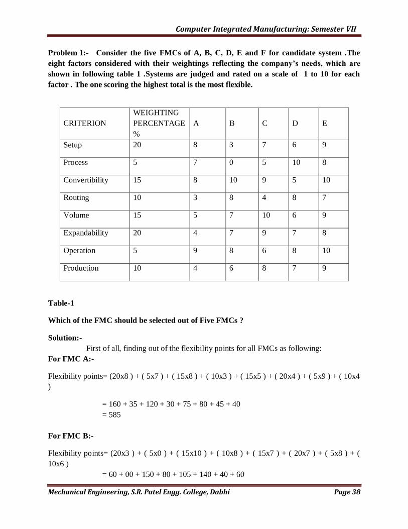
Problem 1:- Consider the five FMCs of A, B, C, D, E and F for candidate system .The
eight factors considered with their weightings reflecting the company’s needs, which are
shown in following table 1 .Systems are judged and rated on a scale of 1 to 10 for each
factor . The one scoring the highest total is the most flexible.
CRITERION
WEIGHTING
PERCENTAGE
%
A
B
C
D
E
Setup 20 8 3 7 6 9
Process 5 7 0 5 10 8
Convertibility 15 8 10 9 5 10
Routing 10 3 8 4 8 7
Volume 15 5 7 10 6 9
Expandability 20 4 7 9 7 8
Operation 5 9 8 6 8 10
Production 10 4 6 8 7 9
Table-1
Which of the FMC should be selected out of Five FMCs ?
Solution:-
First of all, finding out of the flexibility points for all FMCs as following:
For FMC A:-
Flexibility points= (20x8 ) + ( 5x7 ) + ( 15x8 ) + ( 10x3 ) + ( 15x5 ) + ( 20x4 ) + ( 5x9 ) + ( 10x4
)
= 160 + 35 + 120 + 30 + 75 + 80 + 45 + 40
= 585
For FMC B:-
Flexibility points= (20x3 ) + ( 5x0 ) + ( 15x10 ) + ( 10x8 ) + ( 15x7 ) + ( 20x7 ) + ( 5x8 ) + (
10x6 )
= 60 + 00 + 150 + 80 + 105 + 140 + 40 + 60
Computer Integrated Manufacturing: Semester VII
Mechanical Engineering, S.R. Patel Engg. College, Dabhi Page 39
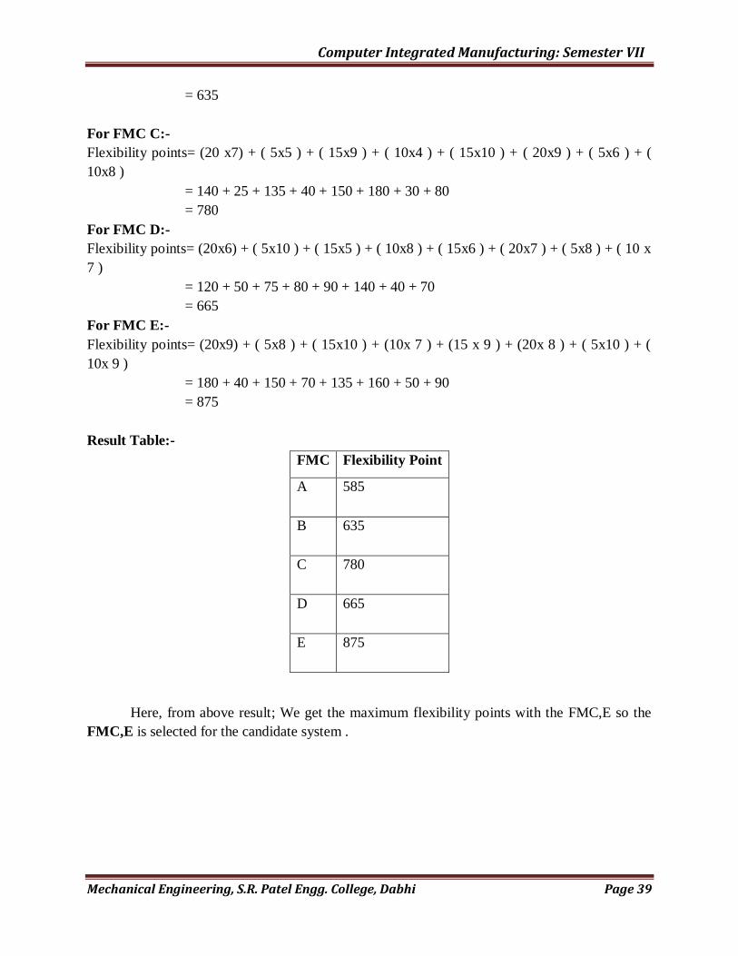
= 635
For FMC C:-
Flexibility points= (20 x7) + ( 5x5 ) + ( 15x9 ) + ( 10x4 ) + ( 15x10 ) + ( 20x9 ) + ( 5x6 ) + (
10x8 )
= 140 + 25 + 135 + 40 + 150 + 180 + 30 + 80
= 780
For FMC D:-
Flexibility points= (20x6) + ( 5x10 ) + ( 15x5 ) + ( 10x8 ) + ( 15x6 ) + ( 20x7 ) + ( 5x8 ) + ( 10 x
7 )
= 120 + 50 + 75 + 80 + 90 + 140 + 40 + 70
= 665
For FMC E:-
Flexibility points= (20x9) + ( 5x8 ) + ( 15x10 ) + (10x 7 ) + (15 x 9 ) + (20x 8 ) + ( 5x10 ) + (
10x 9 )
= 180 + 40 + 150 + 70 + 135 + 160 + 50 + 90
= 875
Result Table:-
FMC Flexibility Point
A 585
B 635
C 780
D 665
E 875
Here, from above result; We get the maximum flexibility points with the FMC,E so the
FMC,E is selected for the candidate system .

Computer Integrated Manufacturing: Semester VII
Mechanical Engineering, S.R. Patel Engg. College, Dabhi Page 40
Problem-2:- The XYZ Company is deciding to purchase the FMC. They have three option
of different FMCs; Say P, Q and R. The weighting of eight factors, as shown in table-2, in
percentage are 15, 10, 5, 20, 10, 15, 10, and 5 respectively. Find the best suitable FMC for
the company system, Use the data given in the following table-2.
CRITERION P Q R
Setup 8 3 7
Process 7 0 5
Convertibility 8 10 9
Routing 3 8 4
Volume 5 7 10
Expandability 4 7 9
Operation 9 8 6
Production 4 6 8
TABLE-2
Which of the FMC should be selected out of Five FMCs based on flexibility points ?
Solution:-
First of all finding out the flexibility points for all FMCs as following:
For FMC P:-
Flexibility points= (15 x8) + (10 x7 ) + ( 5 x 8 ) + (20 x 3 ) + ( 10x5 ) + ( 15x 4 ) + (10x 9 ) + (5
x 4 )
= 120 + 70 + 40 + 60 + 50 + 60 + 90 + 20
= 510
For FMC Q:-
Flexibility points= (15 x3 ) + ( 10x 0 ) + ( 5x10 ) + ( 20x8 ) + ( 10x7 ) + ( 15x7 ) + ( 10x8 ) + (
5x6 )
= 45 + 60 + 50 + 160 + 70 + 105 + 80 + 30
= 540
For FMC R:-
Flexibility points= (15x7) + ( 10x5 ) + ( 5x9 ) + ( 20x 4 ) + ( 10x10 ) + ( 15x9 ) + ( 10 x 6 ) + (
5x 8 )
Computer Integrated Manufacturing: Semester VII
Mechanical Engineering, S.R. Patel Engg. College, Dabhi Page 41
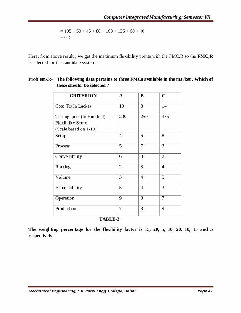
= 105 + 50 + 45 + 80 + 160 + 135 + 60 + 40
= 615
Here, from above result ; we get the maximum flexibility points with the FMC,R so the FMC,R
is selected for the candidate system.
Problem-3:- The following data pertains to three FMCs available in the market . Which of
these should be selected ?
CRITERION A B C
Cost (Rs In Lacks) 10 8 14
Throughputs (In Hundred)
Flexibility Score
(Scale based on 1-10)
200 250 385
Setup 4 6 8
Process 5 7 3
Convertibility 6 3 2
Routing 2 8 4
Volume 3 4 5
Expandability 5 4 3
Operation 9 8 7
Production 7 8 9
TABLE-3
The weighting percentage for the flexibility factor is 15, 20, 5, 10, 20, 10, 15 and 5
respectively

Computer Integrated Manufacturing: Semester VII
Mechanical Engineering, S.R. Patel Engg. College, Dabhi Page 42
Practical:- 05
AIM: Increasing of Unutilized Workstation Capacity of a Complex FMS by Quantitative
Analysis using Bottleneck model.
Problem: 1 Bottleneck model on a simple problem:
A flexible machining system consists of two machining workstations and a load/unload station.
Station 1 is the load/unload station and having single server. Station 2 performs milling
operations and consists of two servers (two identical CNC milling machines).station 3 has one
server that performs drilling (one CNC drill press). The stations are connected by a part min. The
FMS produces two parts, A and B. The part mix fractions and process routings for the two parts
are presented in the table-1 below. The operation frequency fijk = 1.0 for all operations.
Determine:
(a) Maximum production rate of the FMS,
(b) Corresponding production rates of each product,
(c) Utilization of each station, and
(d) Number of busy servers at each station.
Part j Part Mix Pj Operation k Description Station i Process Time
tijk(min)
A
0.4
1 Load 1 4
2 Mill 2 30
3 Drill 3 10
4 Unload 1 2
B
0.6
1 Load 1 4
2 Mill 2 40
3 Drill 3 15
4 Unload 1 2
Table-1

Computer Integrated Manufacturing: Semester VII
Mechanical Engineering, S.R. Patel Engg. College, Dabhi Page 43
Solution:
(a) To compute the FMS production rate, we first need to compute workloads at each
station, so that the bottleneck station can be identified.
WLi =Σ Σ tijk fijk Pj …………………….. (eq.2)
Where WLi = average workload for station i (min)
Tijk = processing time for operation k in process plan j at station i (min)
Fijk = operation frequency for operation k in part j at station i; and
Pj = part mix fraction for part j.
WL1 = [(process time for laod & unload,tijk)( part mix for A,Pj)( Operation frequency,
fijk)]+[( process time for laod & unload,tijk)( part mix for A,Pj)( Operation frequency,
fijk)]
WL1 = (4+2)(0.4)(1.0)+(4+2)(0.6)(1.0)
WL1 = 6.0 min
WL2 = [( Process time for mill, tijk)(Part mix for A, Pj)(operation frequency,fijk)] +
[(Process time for mill, tijk)(Part mix for B, Pj)(operation frequency,fijk)]
WL2 = (30)(0.4)(1.0) + (40)(0.6)(1.0)
WL2 = 36.0 min
WL3 = [( Process time for drill, tijk)(Part mix for A, Pj)(operation frequency,fijk)] +
[(Process time for drill , tijk)(Part mix for B, Pj)(operation frequency,fijk)]
WL3 = 13.0 min
The ststion routing for both parts is same : 1 2 3 1
Now, the workload of the handling system,
WLn+1 = nt tn+1 ………………………………………….( eq.4)
Where WLn+1 = workload of the handling system(min),
nt = mean number of transports
tn+1 = mean transport time per move(min)
WLn+1= 3(3)
WLn+1= 9 min

Computer Integrated Manufacturing: Semester VII
Mechanical Engineering, S.R. Patel Engg. College, Dabhi Page 44
Now the production rate for material handling system,
WL4 = [(Workload of handling system, WLn+1)(Part mix for A, Pj)(Operation frequency,
fijk)]+[ (Workload of handling system, WLn+1)(Part mix for B, Pj)(Operation
frequency, fijk)
WL4 = (9.0)(4.0)(1.0) + (9.0)(0.6)(1.0)
WL4 = 9.0 min
The bottleneck station is identified by finding the largest WLi/si ration.
Here, servers for station 1, s1 = 1
servers for station 2, s2 = 2
servers for station 3, s3 = 1
servers for station 4, s4 = 4 (Station 4: The part handling system)
For station 1, WL1/S1 = 6.0/1 = 6.0 min.
For station 2, WL2/S2 = 36.0/2 = 18.0 min.
For station 3, WL3/S3 = 13.0/1 = 13.0 min.
For station 4, WL4/S4 = 9.0/4 = 2.25 min. (Station 4 : The part handling system)
The maximum ratio occurs at station 2, so it is the bottleneck station that determines the
maximum production rate of all parts made by the system.
Rp* = (s*/WL*)
Where Rp* = maximum production rate of all part styles produced by the system, which is
determined by the capacity of the bottleneck station (pc/min),
s* = number of servers at the bottleneck station =2
WL* = workload at the bottleneck station (min/pc) =36.0
Rp* = (s*/WL*)
Rp* = 2/36.0
Rp* = 0.05555 pc/min = 3.333 pc/hr
(b) To determine production rate of each product, multiply Rp* by its respective part mix
fraction.
Rpj* = (Rp*)Pj = (s*/WL*)Pj………………….(eq.6)
Where, Rpj = maximum production rate of part style j (pc/hr), and
Pj = part mix fraction for part style j.
Computer Integrated Manufacturing: Semester VII
Mechanical Engineering, S.R. Patel Engg. College, Dabhi Page 45
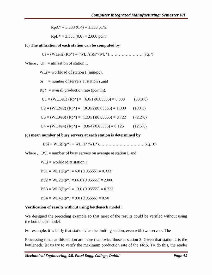
RpA* = 3.333 (0.4) = 1.333 pc/hr
RpB* = 3.333 (0.6) = 2.000 pc/hr
(c) The utilization of each station can be computed by
Ui = (WLi/si)(Rp*) = (WLi/si)(s*/WL*)…………………….(eq.7)
Where , Ui = utilization of station I,
WLi = workload of station I (min/pc),
Si = number of servers at station i ,and
Rp* = overall production rate (pc/min).
U1 = (WL1/s1) (Rp*) = (6.0/1)(0.05555) = 0.333 (33.3%)
U2 = (WL2/s2) (Rp*) = (36.0/2)(0.05555) = 1.000 (100%)
U3 = (WL3/s3) (Rp*) = (13.0/1)(0.05555) = 0.722 (72.2%)
U4 = (WL4/s4) (Rp*) = (9.0/4)(0.05555) = 0.125 (12.5%)
(d) mean number of busy servers at each station is determined by
BSi = WLi(Rp*) = WLi(s*/WL*)……………………………(eq.10)
Where , BSi = number of busy servers on average at station i, and
WLi = workload at station i.
BS1 = WL1(Rp*) = 6.0 (0.05555) = 0.333
BS2 = WL2(Rp*) =3 6.0 (0.05555) = 2.000
BS3 = WL3(Rp*) = 13.0 (0.05555) = 0.722
BS4 = WL4(Rp*) = 9.0 (0.05555) = 0.50
Verification of results without using bottleneck model :
We designed the preceding example so that most of the results could be verified without using
the bottleneck model.
For example, it is fairly that station 2 us the limiting station, even with two servers. The
Processing times at this station are more than twice those at station 3. Given that station 2 is the
bottleneck, let us try to verify the maximum production rate of the FMS. To do this, the reader
Computer Integrated Manufacturing: Semester VII
Mechanical Engineering, S.R. Patel Engg. College, Dabhi Page 46
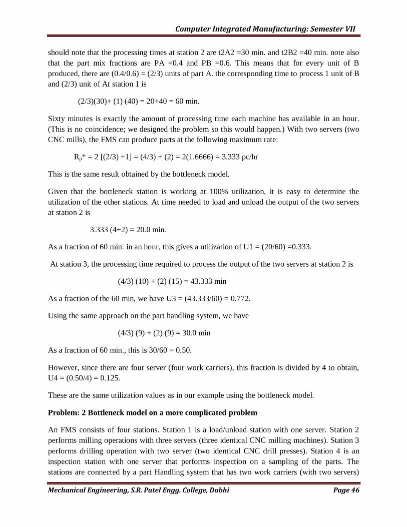
should note that the processing times at station 2 are t2A2 =30 min. and t2B2 =40 min. note also
that the part mix fractions are PA =0.4 and PB =0.6. This means that for every unit of B
produced, there are (0.4/0.6) = (2/3) units of part A. the corresponding time to process 1 unit of B
and (2/3) unit of At station 1 is
(2/3)(30)+ (1) (40) = 20+40 = 60 min.
Sixty minutes is exactly the amount of processing time each machine has available in an hour.
(This is no coincidence; we designed the problem so this would happen.) With two servers (two
CNC mills), the FMS can produce parts at the following maximum rate:
Rp* = 2 [(2/3) +1] = (4/3) + (2) = 2(1.6666) = 3.333 pc/hr
This is the same result obtained by the bottleneck model.
Given that the bottleneck station is working at 100% utilization, it is easy to determine the
utilization of the other stations. At time needed to load and unload the output of the two servers
at station 2 is
3.333 (4+2) = 20.0 min.
As a fraction of 60 min. in an hour, this gives a utilization of U1 = (20/60) =0.333.
At station 3, the processing time required to process the output of the two servers at station 2 is
(4/3) (10) + (2) (15) = 43.333 min
As a fraction of the 60 min, we have U3 = (43.333/60) = 0.772.
Using the same approach on the part handling system, we have
(4/3) (9) + (2) (9) = 30.0 min
As a fraction of 60 min., this is 30/60 = 0.50.
However, since there are four server (four work carriers), this fraction is divided by 4 to obtain,
U4 = (0.50/4) = 0.125.
These are the same utilization values as in our example using the bottleneck model.
Problem: 2 Bottleneck model on a more complicated problem
An FMS consists of four stations. Station 1 is a load/unload station with one server. Station 2
performs milling operations with three servers (three identical CNC milling machines). Station 3
performs drilling operation with two server (two identical CNC drill presses). Station 4 is an
inspection station with one server that performs inspection on a sampling of the parts. The
stations are connected by a part Handling system that has two work carriers (with two servers)

Computer Integrated Manufacturing: Semester VII
Mechanical Engineering, S.R. Patel Engg. College, Dabhi Page 47
and whose mean transport time = 3.5 min. The FMS produce four parts, A, B, C and D. The part
mix fraction and process routing for the four parts are presented in the table below. Note that the
operation frequency at inspection station (f4jk) is less then 1.0 to account for the fact that only
fractions of the part are inspected. Use the data given table-1. Determine:
(a) Maximum production rate of the FMS,
(b) Corresponding production rate of each part,
(c) Utilization of each station in the system, and
(d) The overall FMS utilization.
Part
j
Part Mix
Pj`
Operation
k
Description Station
i
Process
Time
tijk (min)
Frequency
Fijk
A 0.1 1 Load 1 4 1
2 Mill 2 20 1
3 Drill 3 15 1
4 Inspect 4 12 0.5
5 Unload 1 2 1
B 0.2 1 Load 1 4 1
2 Drill 3 16 1
3 Mill 2 25 1
4 Drill 3 14 1
5 Inspect 4 15 0.2
6 Unload 1 2 1
C 0.3 1 Load 1 4 1
2 Drill 3 23 1
3 Inspect 4 8 0.5
4 Unload 1 2 1
D 0.4 1 Load 1 4 1
2 Mill 2 30 1
3 Inspect 4 12 0.333
4 Unload 1 2 1
Table-1

Computer Integrated Manufacturing: Semester VII
Mechanical Engineering, S.R. Patel Engg. College, Dabhi Page 48
Problem 3:-Increasing Unutilized Station capacity:
Use the data of example 2,in which u2 =82.9 %. Determine the production rate of part D that
will increase the utilization of station 2 to 100 %. Also find the new part mix fraction.
Solution:-
Utilization of a workstation is calculated by,
U2=(WL2/S2)(Rp*)
=(WL2/ 3)(0.1389)
Settingthe utilization of station 2 (U2) to 1.0(100 %), we can solve the corresponding WL2
value.
Therefore, WL2=(U2)(S2)/(Rp*)
=(1.0)(3)/(0.1389)
=21.6
This compares with the previous workload value (WL2)of 19.0 min computed in problem 2. A
portion of the workload for both value is accounted for by parts A and B.
This portion is,
WL2(A+B) = (t2A2)(f2A2)(PA)+(t2B3)(f2A3)(PA)
=(20)(1.0)(0.1)+(25)(1.0)(0.2)
=7.0 min
The remaining portion of the workload are due to part D.
For the workload at 100% utilization ,WL2(D) = 21.6-7.0 = 14.6 min
For the workload at 87.9% utilization ,WL2(D)= 19.0-7.0 =12.0 min
We can now use the ratio of these values to calculate the new (increased) production rate for part
D:
RpD=(WL2(D)for 100% utilization /WL2 (D) for 87.9% utilization )*(RpD previous value)
=(14.6/12.0)(3.333)
=(1.2167)(3.333)
=4.055 pc/hr

Computer Integrated Manufacturing: Semester VII
Mechanical Engineering, S.R. Patel Engg. College, Dabhi Page 49
Production rates of the other three producs remoin the same as before . Accordingly, the
Production rate of all parts increases tonthe following :
Rp*=0.833+1.667+2.500+4.055
= 9.055 pc/hr
Although the production rates of the other three products are unchanged ,The increase in
Production rate for part D alters relative part mix fraction .The new values are :
PA=(RpA*)/(Rp*) = (0.833)/(9.055) = 0.092
PB=(RpB*)/(Rp*) = (1.667)(9.055) = 0.184
PC=(RpC*)/(Rp*) = (2.500)(9.055) = 0.276
PD=(RpD*)/(Rp*) = (4.055)(9.055) = 0.448

Computer Integrated Manufacturing: Semester VII
Mechanical Engineering, S.R. Patel Engg. College, Dabhi Page 50
Practical:- 06
AIM: Introduction of GT and part family forming using different method.
GT (Definition)
Group technology is a manufacturing concept in which similar parts are identified and
grouped together in groups or families to take their advantages of their similarities in
manufacturing and design.
The groups of the parts are called as the part families.
Group technology is an operations management philosophy based on the reorganization
that similarities occur in the design and manufacturing of discrete parts.
Objective of GT
To improve productivity
To improve costing accuracy
To improve customer services
To improve variety of the products
To improve effectiveness of machine
To reduce overall cost
To reduce work movement
To reduce overall production cost
To reduce work movement
To reduce overall production time
Obstacle to the application of GT
Implementation of GT requires a large cost in rearranging the plant into group.
There is no accepted GT standard so there is no common implementation approach,
and implementation is often difficult.
Installing a coding and classification system requires a large amount of time and effort.
If Communication between design engineering and manufacturing is not proper then it
is may cause the delay in the manufacturing.
Defect in the coding system may cause the defect in the machining.
There are large numbers of GT codes.
It is not suitable when very wide varieties of products are carried out.
Types of layout
There are two types of lay out.

Computer Integrated Manufacturing: Semester VII
Mechanical Engineering, S.R. Patel Engg. College, Dabhi Page 51
1. Process layout
2. GT layout
1. Process layout
Fig. 1 process layout
Consider a process layout as shown in figure 1 .machines are arranged in the group.
All the lathes are arranged in the same raw, all the drilling machines and milling
machines are also arranged in the one section.
During the manufacturing of parts has to move in between the sections.
It will result in the high material handling and material movement.
ASSEMBLY
GRINDING
LATHE
LATHE
LATHE
ASSEMBLY
DRILLING
DRILLING
DRILLING
GRINDING
ASSEMBLY
MILLING
MILLING
MILLING ASSEMBLY

Computer Integrated Manufacturing: Semester VII
Mechanical Engineering, S.R. Patel Engg. College, Dabhi Page 52
2. GT layout
Fig. 2 GT layout
Now in the GT layout the machines are arranged as per their groups or cell require to
manufacture a part.
The layout is shown in the figure 2.
The number of machines are same but there will be a large reduction in the time as the
material transfer reduces.
Part family
The group of parts or component is called part family. This group is carried out to reduce the
over all manufacturing cost and to improve the productivity. The parts are grouped according to
their similarities. These similarities are of two types.
1. Design attributes.
2. Manufacturing attributes.
In the design attributes the parts are families‟ according to shape, size, surface roughness,
raw material, etc.
ASSEMBLY
LATHE
DRILLING
DRILLING
MILLING
ASSEMBLY
LATHE MILLING DRILLING ASSEMBLY
STORAGE
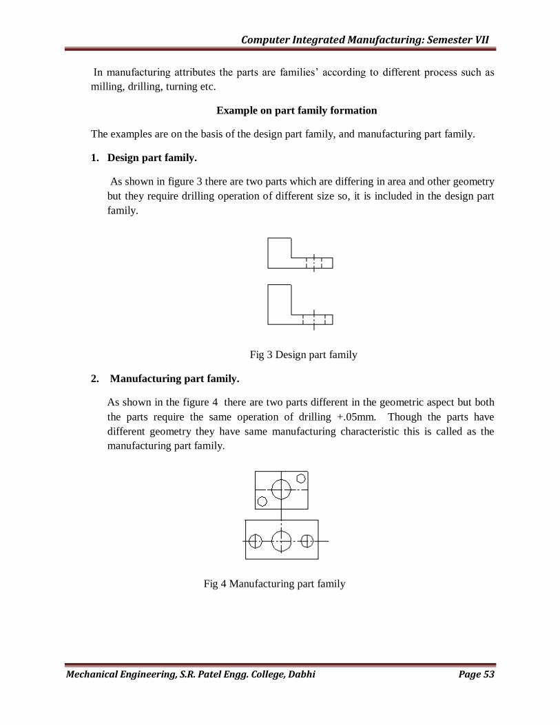
Computer Integrated Manufacturing: Semester VII
Mechanical Engineering, S.R. Patel Engg. College, Dabhi Page 53
In manufacturing attributes the parts are families‟ according to different process such as
milling, drilling, turning etc.
Example on part family formation
The examples are on the basis of the design part family, and manufacturing part family.
1. Design part family.
As shown in figure 3 there are two parts which are differing in area and other geometry
but they require drilling operation of different size so, it is included in the design part
family.
Fig 3 Design part family
2. Manufacturing part family.
As shown in the figure 4 there are two parts different in the geometric aspect but both
the parts require the same operation of drilling +.05mm. Though the parts have
different geometry they have same manufacturing characteristic this is called as the
manufacturing part family.
Fig 4 Manufacturing part family
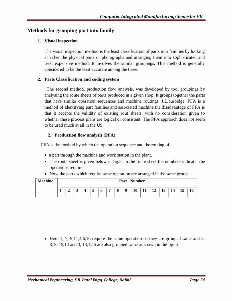
Computer Integrated Manufacturing: Semester VII
Mechanical Engineering, S.R. Patel Engg. College, Dabhi Page 54
Methods for grouping part into family
1. Visual inspection
The visual inspection method is the least classification of parts into families by looking
at either the physical parts or photographs and arranging them into sophisticated and
least expensive method. It involves the similar groupings. This method is generally
considered to be the least accurate among the three.
2. Parts Classification and coding system
The second method, production flow analysis, was developed by tool groupings by
analysing the route sheets of parts produced in a given shop. It groups together the parts
that have similar operation sequences and machine routings. J.L.burbidge. PFA is a
method of identifying part families and associated machine the disadvantage of PFA is
that it accepts the validity of existing rout sheets, with no consideration given to
whether these process plans are logical or consistent. The PFA approach does not seem
to be used much at all in the US.
2. Production flow analysis (PFA)
PFA is the method by which the operation sequence and the routing of
a part through the machine and work station in the plant.
The route sheet is given below in fig.5. In the route sheet the numbers indicate the
operations require.
Now the parts which require same operation are arranged in the same group.
Here 1, 7, 9,11,4,6,16 require the same operation so they are grouped same and 2,
8,10,15,14 and 3, 13,12,5 are also grouped same as shown in the fig. 6
Machine Part Number
1 2 3 4 5 6 7 8 9 10 11 12 13 14 15 16

Computer Integrated Manufacturing: Semester VII
Mechanical Engineering, S.R. Patel Engg. College, Dabhi Page 55
Fig 5 Route sheet data before grouping.
Fig.6 Route sheet data after grouping.
Quiz
1. Explain the group technology in brief and give the objectives of it
2. Explain the part family.
Lathe X X X X X X X X X X X X
Milling X X X X X X X X X X X
Drilling X X X X X X X X X X X X X X
Grinding X X X X X X X X X X X X
Machine
Part Number
1 7 9 11 4 6 16 2 8 10 15 14 3 13 12 5
L X X X X X X X
M X X X X X X X
D X X X X X X
G X X X X X
L X X X X X
D X X X X X
G X X X x
M X X X X
D X X X
G X X X

Computer Integrated Manufacturing: Semester VII
Mechanical Engineering, S.R. Patel Engg. College, Dabhi Page 56
3 enlist the methods of grouping the parts in to part families and explain any two of them.
4 explain hierarchical code and hybrid code structure.
5 explain optiz part classification and coding system
6. Limitations of group technology

Computer Integrated Manufacturing: Semester VII
Mechanical Engineering, S.R. Patel Engg. College, Dabhi Page 57
Practical: - 07
AIM:- Grouping Parts & Machines By Rank Order Clustering
The rank order clustering technique, first proposed by King 26 , is specifically applicable in
production flow analysis. It is an easy & easy-to-use algorithm for grouping machines into
cells. In a starting part machine incidence matrix that might be compiled to document the part
routings in a machine shop, the occupied locations in the matrix are organized in seemingly
random fashion. Rank order clustering works by reducing the part machine incidence matrix to
a set of a diagonalized blocks that represent part families & associated machine groups.
Starting with part incidence matrix , the algorithm consists of the following steps :---
1) In each row of matrix , read the series of 1‟s & 0‟s (blank entries = 0‟s) from left to right as a
binary number. Rank the rows in order of decreasing value. In case of a tie , rank the rows in
the same order as they appear in the current matrix.
2) Numbering from top to bottom, is the current order of rows the same as the rank order
determined in the previous step? If yes, go to step 7. If no go to the following steps.
3) Reorder the rows in the part machine incidence matrix by listing them in the decreasing rank
order , starting from the top.
4) In each column of the matrix , read the series of 1‟s & 0‟s (blank entries = 0‟s) from top to
bottom as a binary number. Rank the columns in the order of decreasing value . In case of a tie
, rank the columns in the same order as they appear in the current matrix.
5) Numbering from left to right , is the current order of columns the same as the rank order
determined in the previous step? If yes, go to step 7. If no go to the following steps.
6) Reorder the columns in the part machine incidence matrix by listing them in the decreasing
rank order , starting with the left columns Go to step 1.
7) Stop.
For readers accustomed to evaluating binary numbers in step 1 & 4., it might be helpful to
convert each binary no. into its decimal equivalent. It is as follows:- 1 * 28
+ 0 * 27
+0 * 26
+ 1
* 25
+ 0 * 24
+ 0 * 23
+ 0 * 22
+ 1 * 21
+ 0 * 20
= 256 + 32 + 2 =290. It should be mentioned
that decimal conversion becomes impractical for large no. of parts found in practice, &
comparison of the binary nos. is preferred.
******************** Problem Description: ******************
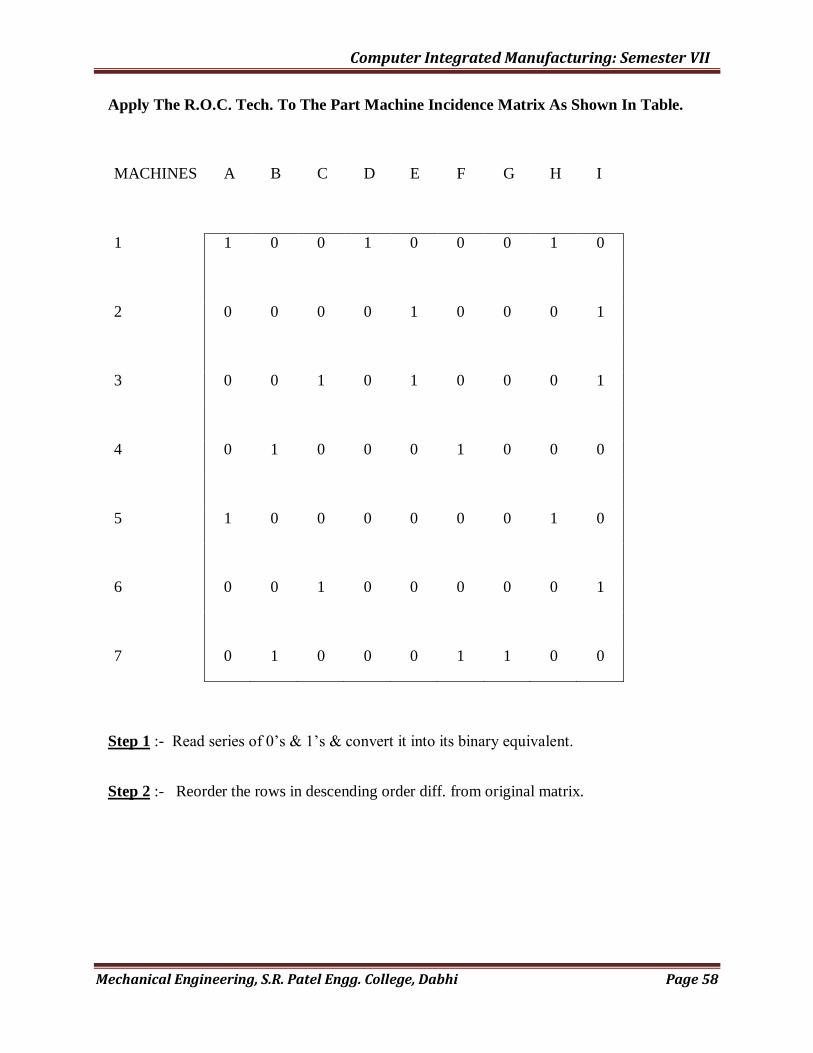
Computer Integrated Manufacturing: Semester VII
Mechanical Engineering, S.R. Patel Engg. College, Dabhi Page 58
Apply The R.O.C. Tech. To The Part Machine Incidence Matrix As Shown In Table.
MACHINES A B C D E F G H I
1 1 0 0 1 0 0 0 1 0
2 0 0 0 0 1 0 0 0 1
3 0 0 1 0 1 0 0 0 1
4 0 1 0 0 0 1 0 0 0
5 1 0 0 0 0 0 0 1 0
6 0 0 1 0 0 0 0 0 1
7 0 1 0 0 0 1 1 0 0
Step 1 :- Read series of 0‟s & 1‟s & convert it into its binary equivalent.
Step 2 :- Reorder the rows in descending order diff. from original matrix.
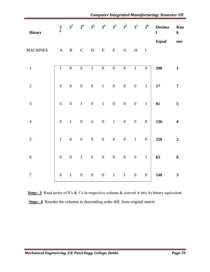
Computer Integrated Manufacturing: Semester VII
Mechanical Engineering, S.R. Patel Engg. College, Dabhi Page 59
Binary
28
27 2
6 2
5 2
4 2
3 2
2 2
1 2
0 Decima
l
Ran
k
Equal nos
MACHINES A B C D E F G H I
1 1 0 0 1 0 0 0 1 0 290 1
2 0 0 0 0 1 0 0 0 1 17 7
3 0 0 1 0 1 0 0 0 1 81 5
4 0 1 0 0 0 1 0 0 0 136 4
5 1 0 0 0 0 0 0 1 0 258 2
6 0 0 1 0 0 0 0 0 1 65 6
7 0 1 0 0 0 1 1 0 0 140 3
Step:- 3 Read series of 0‟s & 1‟s in respective column & convert it into its binary equivalent
Step:- 4 Reorder the columns in descending order diff. from original matrix

Computer Integrated Manufacturing: Semester VII
Mechanical Engineering, S.R. Patel Engg. College, Dabhi Page 60
Step:- 5 & 6 :--
Preceding from step 6 back to steps 1 & 2 we see that reordering of rows & columns provide
descending value & algorithm is concluded (step 7). A solution is given in the following table.
MACHINES A B C D E F G H I Binary
1 0 0 1 0 0 0 1 0 26
5 1 0 0 0 0 0 0 1 0 25
7 0 1 0 0 0 1 1 0 0 24
4 0 1 0 0 0 1 0 0 0 23
3 0 0 1 0 1 0 0 0 1 22
6 0 0 1 0 0 0 0 0 1 21
2 0 0 0 0 1 0 0 0 1 20
Decimal 96 24 6 64 5 24 16 96 7
Rank 1 4 8 3 9 5 6 2 7

Computer Integrated Manufacturing: Semester VII
Mechanical Engineering, S.R. Patel Engg. College, Dabhi Page 61
MACHINES A H D B F G I C E
1 1 1 1
5 1 1 0
7 1 1 1
4 1 1 0
3 1 1 1
6 1 1 0
2 1 0 1
This represents the ideal case because the part families & associated machine cells are
completely segregated.
********************* Problem Description ***********************
(Overlapping Machine Requirements)
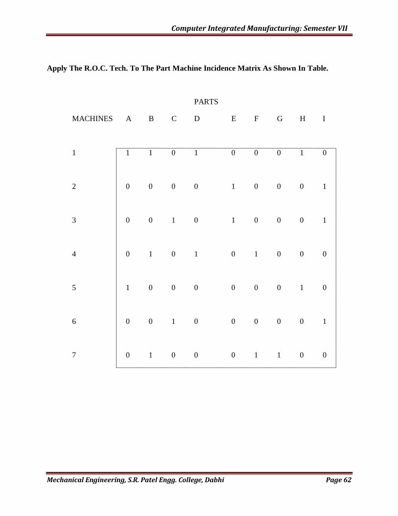
Computer Integrated Manufacturing: Semester VII
Mechanical Engineering, S.R. Patel Engg. College, Dabhi Page 62
Apply The R.O.C. Tech. To The Part Machine Incidence Matrix As Shown In Table.
PARTS
MACHINES A B C D E F G H I
1 1 1 0 1 0 0 0 1 0
2 0 0 0 0 1 0 0 0 1
3 0 0 1 0 1 0 0 0 1
4 0 1 0 1 0 1 0 0 0
5 1 0 0 0 0 0 0 1 0
6 0 0 1 0 0 0 0 0 1
7 0 1 0 0 0 1 1 0 0
Computer Integrated Manufacturing: Semester VII
Mechanical Engineering, S.R. Patel Engg. College, Dabhi Page 63
Practical: - 08
Aim - Study and Demonstration on Robots.
1) Introduction of Robot.
2) Robot anatomy. -- Joints and links
i) Linear joint
ii) Orthogonal joint.
iii) Rotational joint.
iv) Twisting joint.
v) Revolving joint.
3) Robot configurations.-
i) Polar configuration.
ii) Cylindrical configuration.
iii) Cartesian coordinate robot.
iv) Jointed arm robot.
v) SCARA
4) Robot drives system.
5) Accuracy and repeatability.
6) Types of robot programming.
7) Safety monitoring.
8) End effectors and sensors in robots.
9) Application of robots.
10) Programming for some robotic application
Answer:
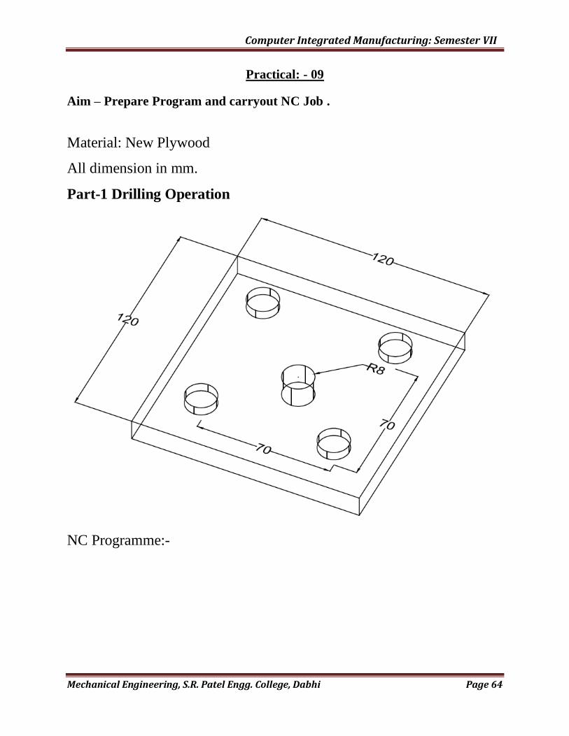
Computer Integrated Manufacturing: Semester VII
Mechanical Engineering, S.R. Patel Engg. College, Dabhi Page 64
Practical: - 09
Aim – Prepare Program and carryout NC Job .
Material: New Plywood
All dimension in mm.
Part-1 Drilling Operation
NC Programme:-

Computer Integrated Manufacturing: Semester VII
Mechanical Engineering, S.R. Patel Engg. College, Dabhi Page 65
Part-2 Cutting Operation
NC Programme:-

Computer Integrated Manufacturing: Semester VII
Mechanical Engineering, S.R. Patel Engg. College, Dabhi Page 66
Part-3 Cutting Operation
NC Programme:-

Computer Integrated Manufacturing: Semester VII
Mechanical Engineering, S.R. Patel Engg. College, Dabhi Page 67
Part-4 Cutting Operation
NC Programme:-