sms design method in 3d geometry: examples and applications
TRANSCRIPT

1
SMS design methodin 3D geometry:
examples and applicationsPablo Benítez, J.C. Miñano,
J. Blen, R. Mohedano, J. Chaves, O. Dross,M. Hernández, J.L. Álvarez, W. Falicoff
Light Prescriptions Innovators LLC
2
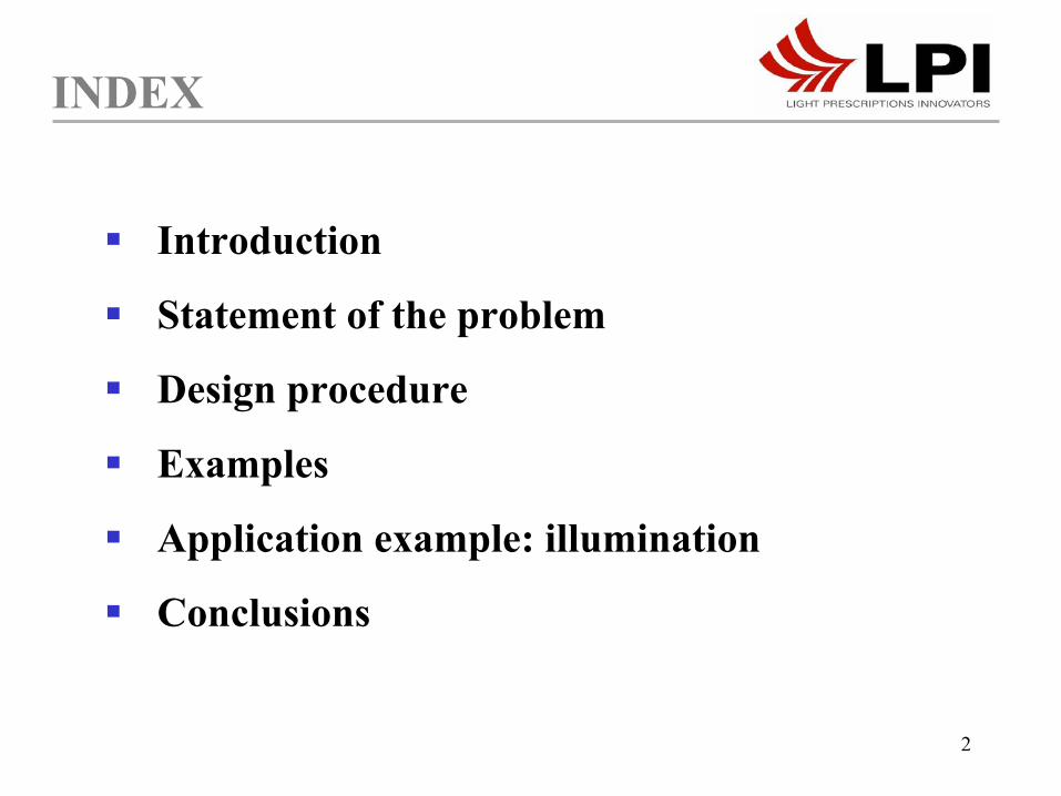
INDEX
Introduction
Statement of the problem
Design procedure
Examples
Application example: illumination
Conclusions
3
Free-form optics introduce degrees of freedom to solve nonimaging and imaging design problems with no symmetric solutions
Present manufacturing technology allows for free-form surfaces with high precision
Few nonimaging design tools are available:
• Most of them for punctual sources• All of them for only 1 free-form surface
INTRODUCTION
4
The SMS3D method designs simultaneously 2 free-form surfaces, which allows the control of extended sources
First example (SPIE’99): sharp-edge imaging lens that showed the perfect imaging of two object points in 3D
INTRODUCTION

5
B’
The SMS3D method designs simultaneously 2 free-form surfaces, which allows the control of extended sources
INTRODUCTION
First example (SPIE’99): sharp-edge imaging lens that showed the perfect imaging of two points in 3D
A’
y
zx
edge
B
A

6
The SMS3D method designs simultaneously 2 free-form surfaces, which allows the control of extended sources
First example (SPIE’99): sharp-edge imaging lens that showed the perfect imaging of two object points in 3D
INTRODUCTION
Last developments (here, SPIE’03): Generalization of the SMS3D*, with application to non-imaging design problems
*patent pending
7
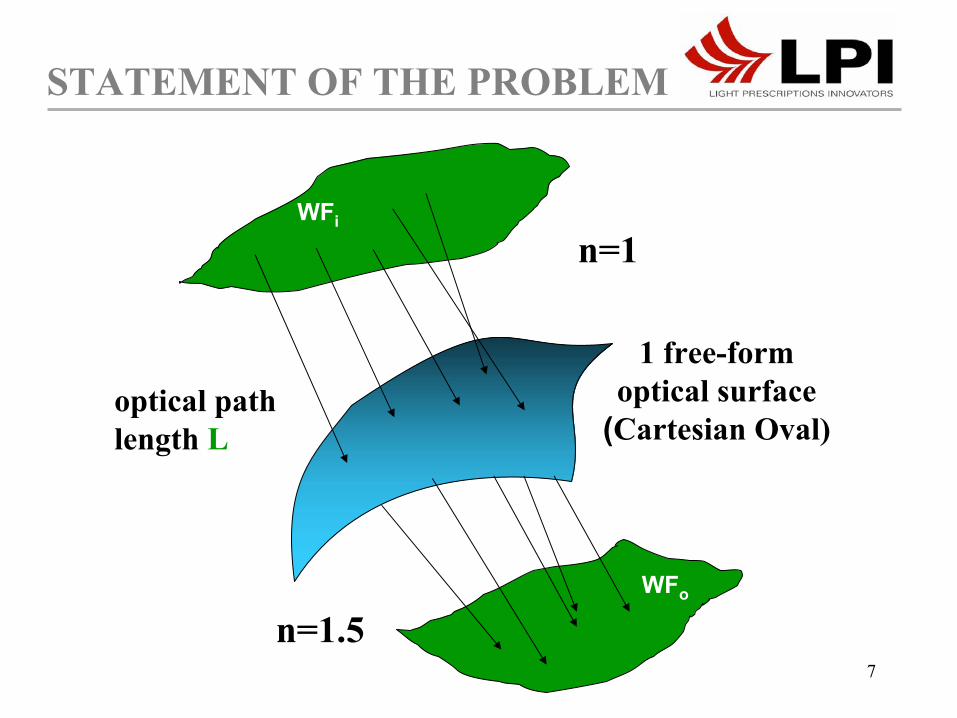
STATEMENT OF THE PROBLEM
1 free-form optical surface
(Cartesian Oval)optical path length L
WFi
WFo2WFo
n=1
n=1.5
8
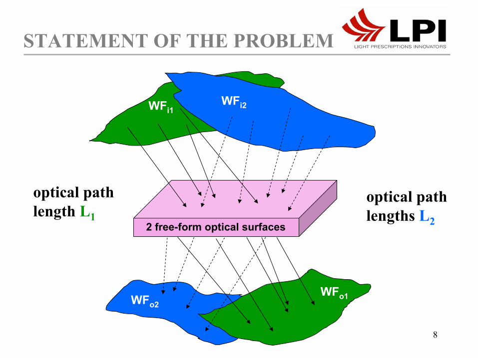
STATEMENT OF THE PROBLEM
2 free-form optical surfaces
optical path length L1
optical path lengths L2
WFi1
WFo2WFo1
WFi2
9
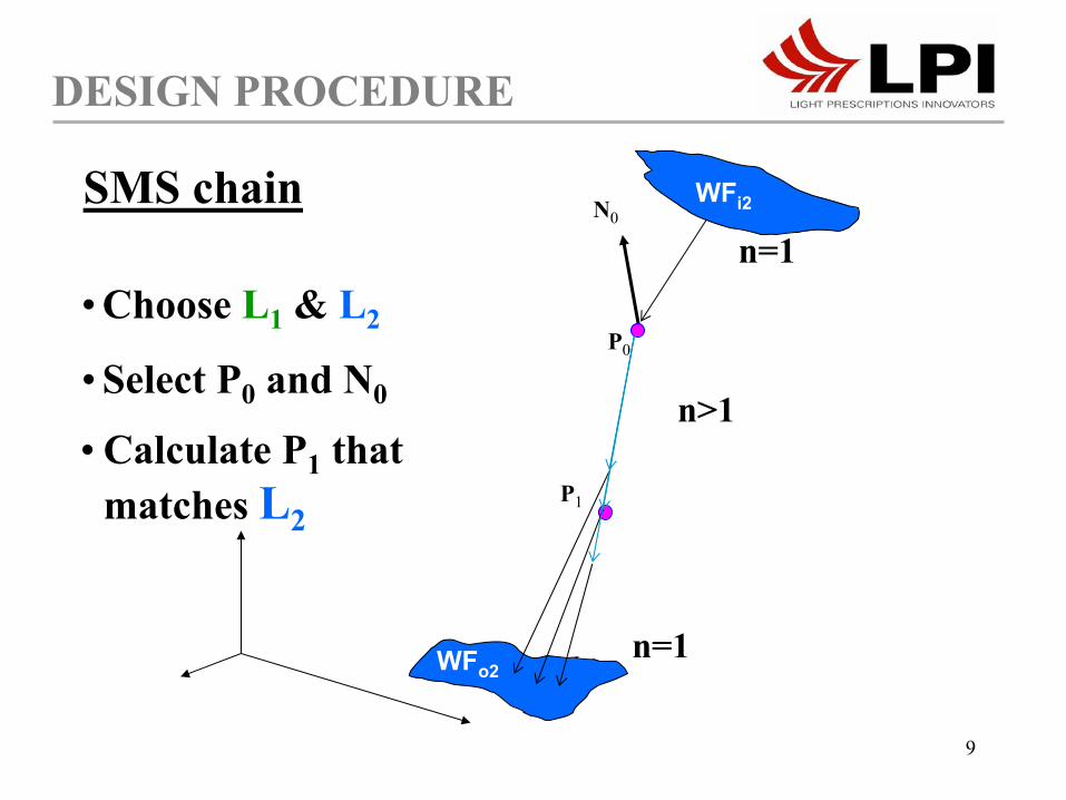
DESIGN PROCEDURE
N0SMS chain
n=1
n=1
n>1
• Choose L1 & L2
• Select P0 and N0
• Calculate P1 that matches L2
WFi2
WFo2
P0
P1
10
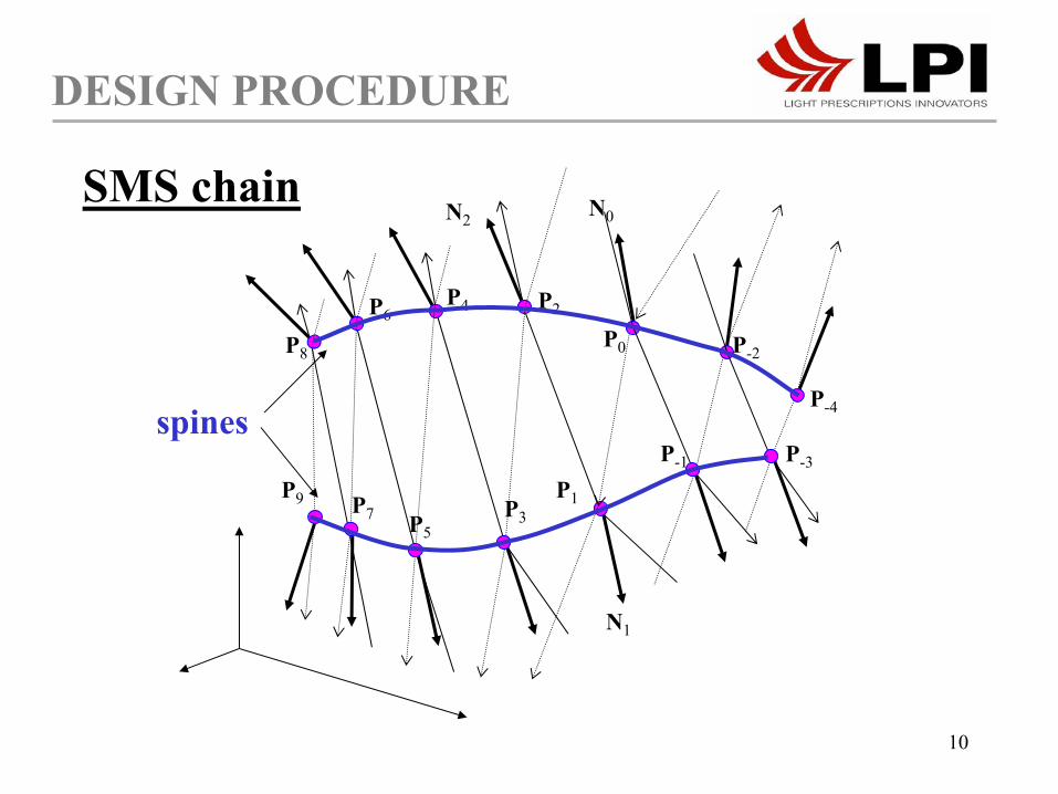
DESIGN PROCEDURE
P0
N0
N1
P2
N2
P-2
P-4
P-1 P-3
P4P6
P8
P3P5P7
P9
spines
SMS chain
P1

11
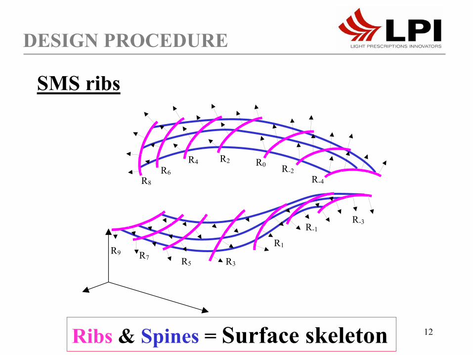
DESIGN PROCEDURE
R0 R-2R-4
R-3R-1
R1R3
R5
R2R4R6
R8
R7
R9
τN0
M
Seed rib R0
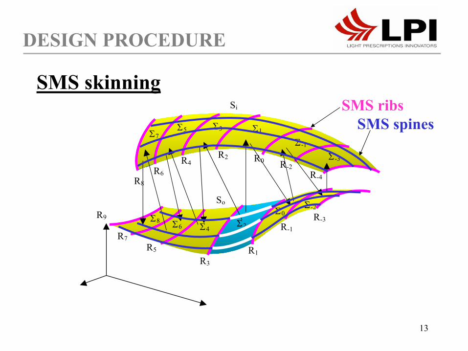
SMS ribs
Ribs & Spines = Surface skeleton
12
DESIGN PROCEDURE
R0
R1
R2R-2
R-4
R-1R-3
R4R6
R8
R3R5R7
R9
SMS ribs
Ribs & Spines = Surface skeleton
13
R1R3
R2
Σ0
Σ1
Σ2
Σ-2
Σ7 Σ-1
Σ-3
Σ4 Σ6 Σ8
Σ3 Σ5
Si
So
R0
R1
R2 R-2
R-4
R-1 R-3
R4 R6
R8
R3 R5
R7
R9
DESIGN PROCEDURE
SMS skinningSMS ribs
SMS spines

14
DESIGN PROCEDURE
2. SMS spine with WF1 & WF3
WFi1WFi2
2 free-form optical surfaces
WFo2WFo1
WFi3
WFo3
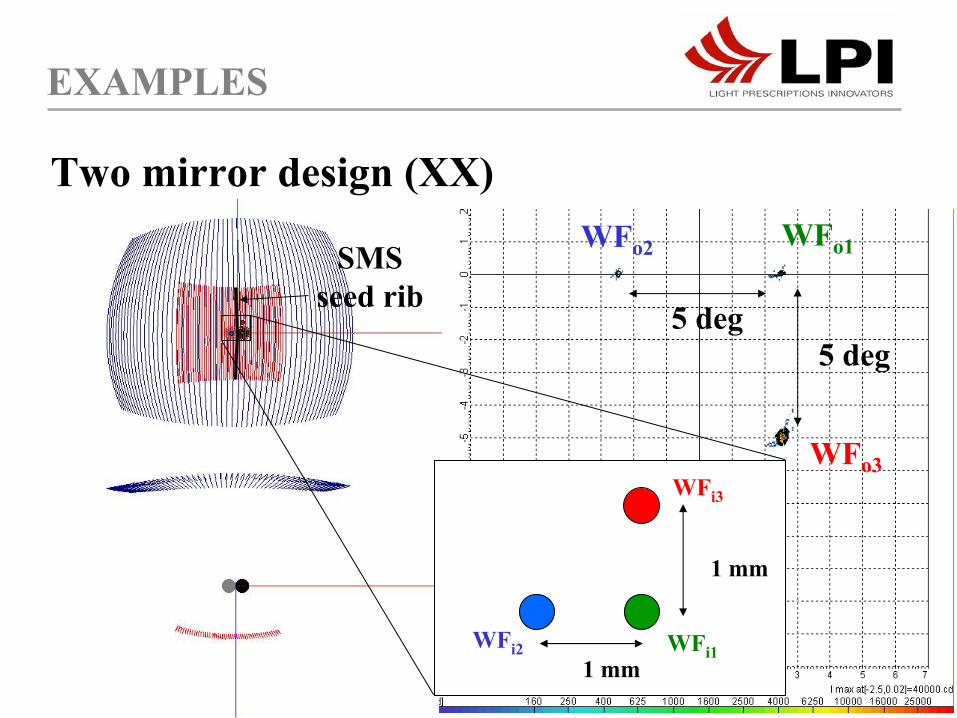
Seed rib R0
Seed rib selection criterion: 1. Geometrically constrained by application
Full coupling of WF1
and WF2
Coupling of WF3
along the seed rib
15
WFo1WFo2
WFo3
5 deg5 deg
EXAMPLES
Two mirror design (XX)
WFi2 WFi1
WFi3
1 mm
1 mm
SMS seed rib
16
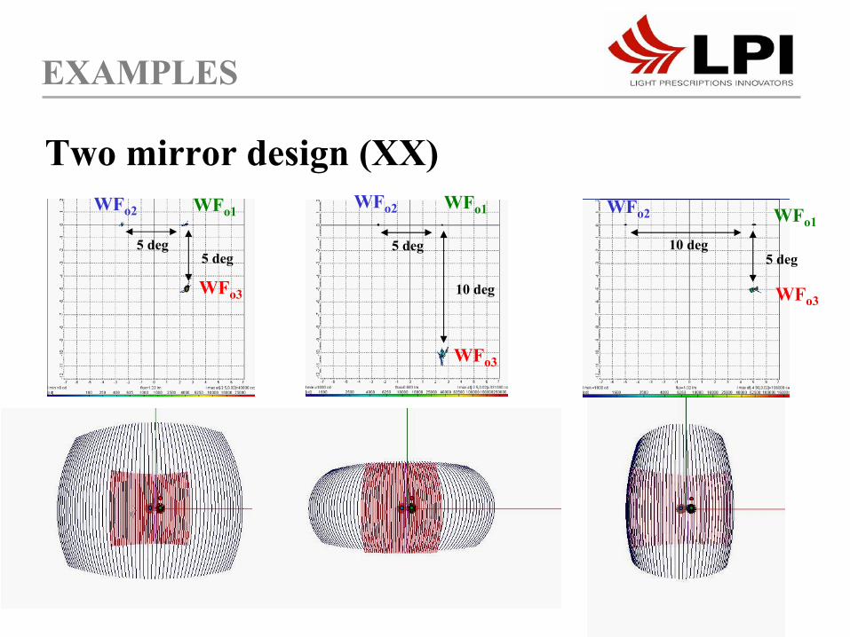
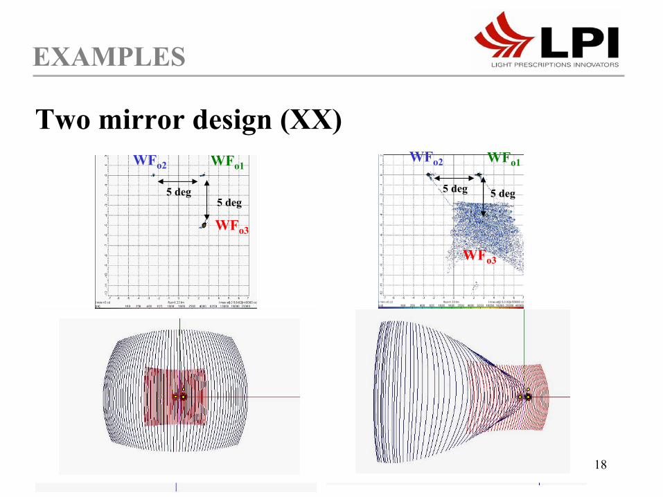
EXAMPLES
Two mirror design (XX)WFo1WFo2
WFo3
5 deg5 deg
WFo1
WFo3
WFo2
10 deg5 deg
WFo3
5 deg
10 deg
WFo1WFo2
17
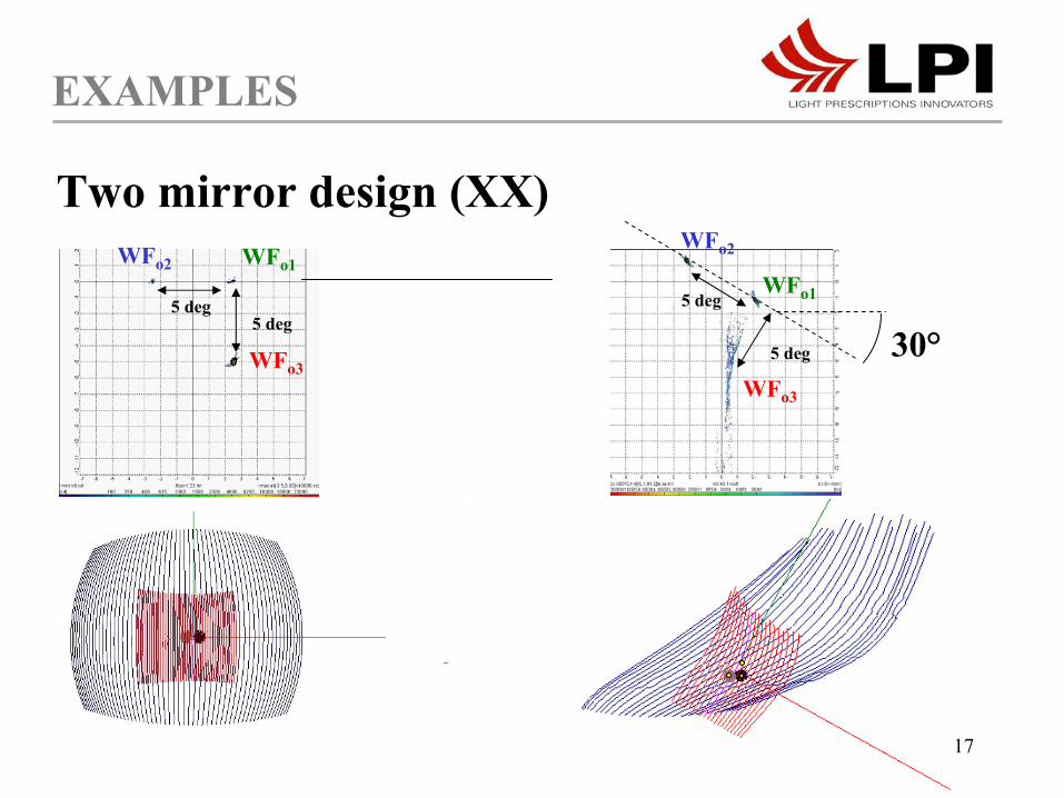
EXAMPLES
Two mirror design (XX)
30°
WFo1WFo2
WFo3
5 deg5 deg
WFo1
WFo2
WFo3
5 deg
5 deg
18
EXAMPLES
Two mirror design (XX)WFo1WFo2
WFo3
5 deg5 deg
WFo1WFo2
WFo3
5 deg 5 deg
19
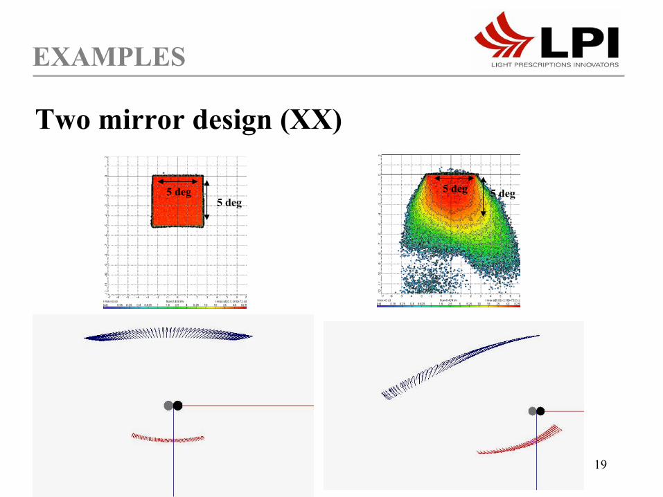
EXAMPLES
Two mirror design (XX)
5 deg5 deg
5 deg 5 deg

20
RXI 3D
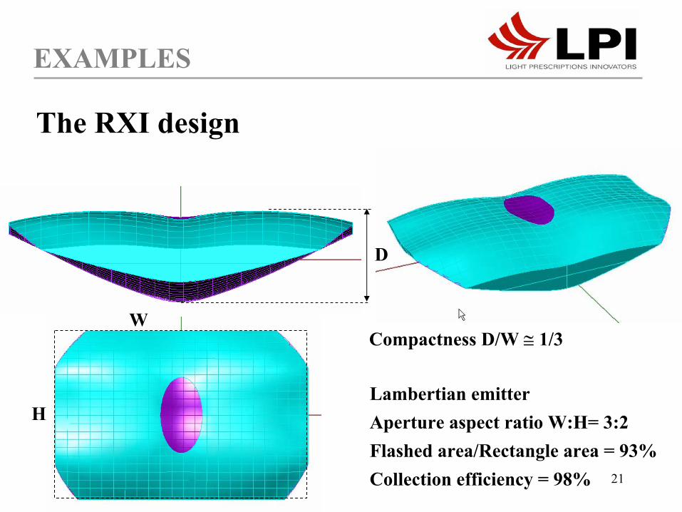
EXAMPLES
The RXI design
RXI 2D*mirror
mirror
α
*US patent application 09/810,959 in allowance
21
EXAMPLES
The RXI design
Lambertian emitterAperture aspect ratio W:H= 3:2Flashed area/Rectangle area = 93%Collection efficiency = 98%
H
W
D
Compactness D/W ≅ 1/3

22
V
H
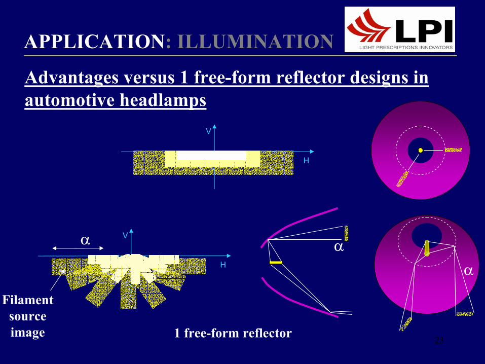
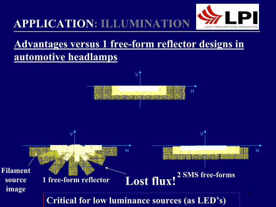
APPLICATION: ILLUMINATION
Advantages versus 1 free-form reflector designs in automotive front lighting
Source Pinholes Images
HL Optical System
Screen at 25 m
23
V
H
V
H
APPLICATION: ILLUMINATION
1 free-form reflector
Filament source image
Advantages versus 1 free-form reflector designs in automotive headlamps
α αα
24
V
H
V
H
APPLICATION: ILLUMINATION
Critical for low luminance sources (as LED’s)
1 free-form reflectorFilament
source image
Lost flux!
Advantages versus 1 free-form reflector designs in automotive headlamps
2 SMS free-forms
V
H
25
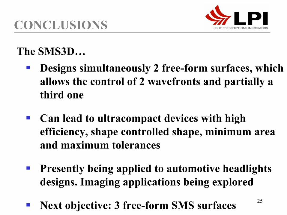
Designs simultaneously 2 free-form surfaces, which allows the control of 2 wavefronts and partially a third one
Can lead to ultracompact devices with high efficiency, shape controlled shape, minimum area and maximum tolerances
Presently being applied to automotive headlights designs. Imaging applications being explored
Next objective: 3 free-form SMS surfaces
CONCLUSIONS
The SMS3D…
26
THE END

27
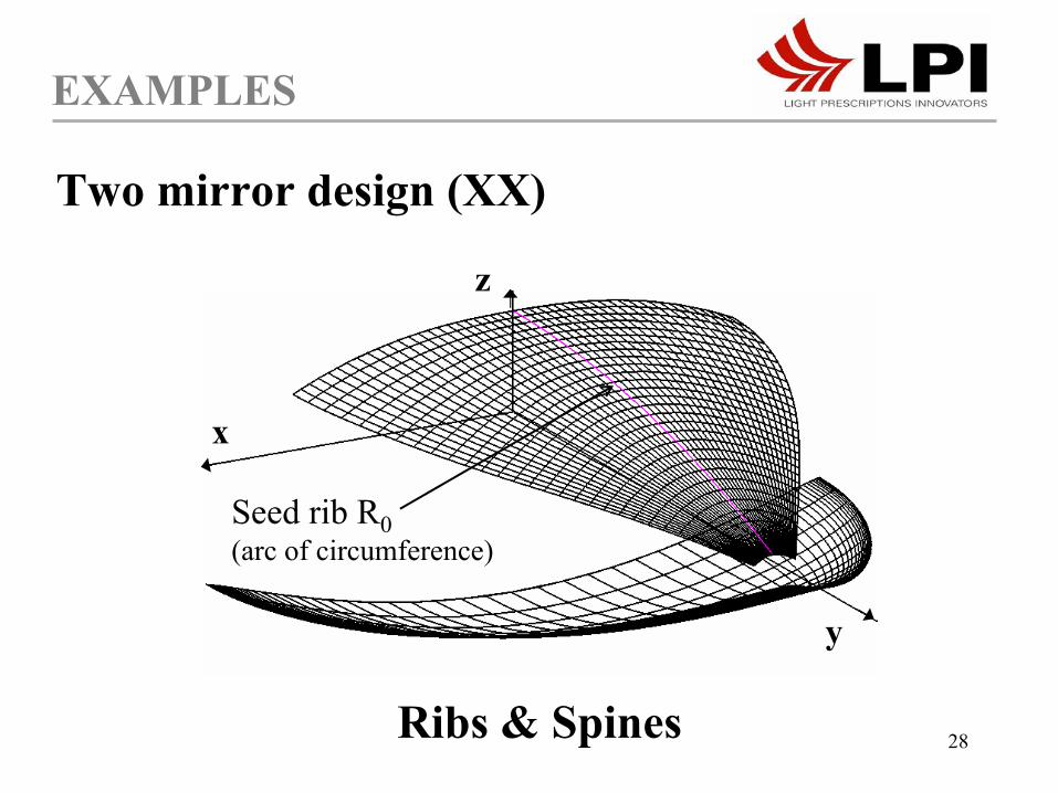
EXAMPLES
Wi2
Wi1
y
x
z
Seed rib R0 (arc of circumference)
Wo2Wo1
Two mirror design (XX)
28
EXAMPLES
Seed rib R0(arc of circumference)
y
x
z
Ribs & Spines
Two mirror design (XX)
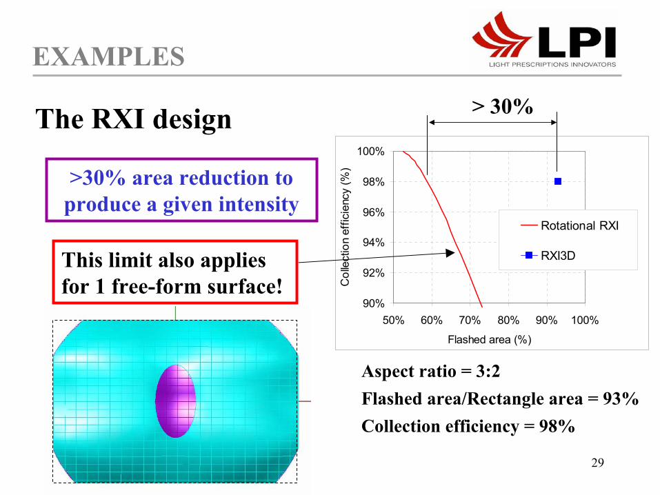
29
90%
92%
94%
96%
98%
100%
50% 60% 70% 80% 90% 100%
Flashed area (%)C
olle
ctio
n ef
ficie
ncy
(%)
Rotational RXI
RXI3D
EXAMPLES
The RXI design
Aspect ratio = 3:2Flashed area/Rectangle area = 93%Collection efficiency = 98%
> 30%
>30% area reduction to produce a given intensity
This limit also applies for 1 free-form surface!
30
APPLICATION: ILLUMINATION
The higher control (sizes, rotation) of source image projection provides
Exit aperture shape controlled without efficiency lossHigher efficiencyIncreased tolerances to source displacements
Critical for low luminance sources (as LED’s)
Advantages versus 1 free-form reflector designs in automotive headlamps
31
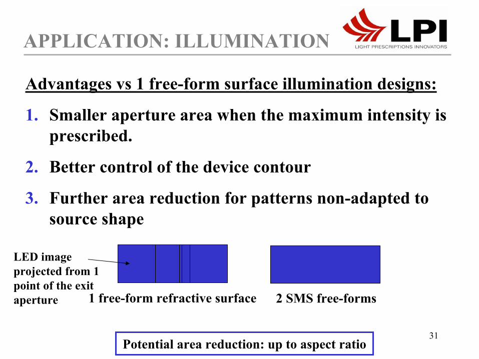
APPLICATION: ILLUMINATION
Advantages vs 1 free-form surface illumination designs:
1. Smaller aperture area when the maximum intensity is prescribed.
2. Better control of the device contour
3. Further area reduction for patterns non-adapted to source shape
Far-field area to illuminate 2 SMS free-forms1 free-form refractive surface
LED imageprojected from 1 point of the exit aperture
Potential area reduction: up to aspect ratio

32
APPLICATION: ILLUMINATION
Potential advantages vs 1 free-form designs:
3. Higher control (sizes, rotation) of source image projection
Critical for low luminance sources (as LED’s) and limited area ⇒ big source projected imagesExit aperture shape controlled without efficiency lossHigher tolerances to source displacements for a given exit area
4. Simultaneous prescriptions of the far-field intensity and near-field illuminance can be achieved
33
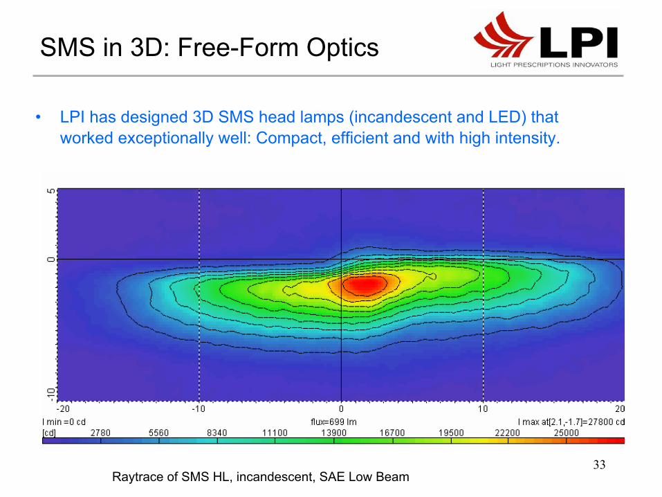
• LPI has designed 3D SMS head lamps (incandescent and LED) that worked exceptionally well: Compact, efficient and with high intensity.
SMS in 3D: Free-Form Optics
Raytrace of SMS HL, incandescent, SAE Low Beam