smoke fans 327 - nuairenuaire.info/catalogue/smokefans.pdfthe majority of fire related mortalities...
TRANSCRIPT

327nuaire.co.uk
SMOKE FANS 327
FAN TYPE FAN LOCATION MAX PAGEPERFORMANCE
IMPULSE AXIAL SMOKE 1.8m3/s 330
IMPULSE CENTRIFUGAL SMOKE 2.69m3/s 331
AXUS CONTRA-ROTATING SMOKE 42m3/s 334
AXUS RUN & STANDBY SMOKE 45m3/s 338
HT AXUS SMOKE 64m3/s 342
HT SQUIF SMOKE 6.5m3/s 366
HT TWIN SQUIF SMOKE 6.2m3/s 374

029 2085 8200328
SMOKE CONTROL - NEW DIRECTIONS
Nuaire offers design through to commissioning for applications
such as underground car parks.
Nuaire provides the total package for smoke control with
schemes designed to fully comply with statutory and regulatory
requirements. Our team of skilled engineers include experienced
staff who were responsible for introducing the first Impulse
systems to the UK for car park applications.
The majority of fire related mortalities are because people have been asphyxiated by deadly toxic gases
that are produced during a fire.
One of the biggest hazards in the event of a fire is that of smoke inhalation. It is essential to provide adequate
ventilation in car parks, even though modern cars have been fitted with catalytic converters they still produce
surprisingly high levels of harmful pollutants. Our ventilation systems remove combustible gases, fuel spill
vapours, uncombusted fuel particles and displace oxygen.
By redirecting combustion gases to where they will do least harm, valuable time is available to evacuate
personnel to safety and provide protection to buildings.
The car park Impulse system is used to control and remove contaminants on a day-to-day basis, whilst
ensuring smoke is removed quickly and efficiently in the event of a fire. Strategically positioned Impulse fans,
mounted on the ceiling, create a virtual smoke barrier ensuring quick and effective clearance whilst keeping
the rest of the car park smoke free.
Eliminating the need for complicated ductwork systems optimises space and saves money. The system is also
extremely energy efficient as it monitors the air quality and operates the system at its optimum level,
reducing the running costs by up to 40% compared with traditional ducted systems. Also, fewer fans are
required as they distribute the air over such a large area.
Nuaire’s range of services and support can be tailored to satisfy the individual requirements of underground
car parks, shopping centres and warehouses or pressurisation systems for commercial, office and hotel
buildings.
DESIGN
CO-ORDINATION
MANUFACTURE
CERTIFIED
INSTALLATION
COMMISSIONING

329
SMOKE FANS
C AR PARK IMPULSE SYSTEM
TECHNIC AL INFORMATION
nuaire.co.ukDownload specification from www.nuaire.co.uk/specifications
HOW THE SYSTEM WORKS
The system runs at low speed ensuring that Carbon Monoxidelevels and other contaminants are kept within acceptable limits.Strategically placed detectors monitor the air and only control the units which can directly effect the condition.
If a fire starts in one of the vehicles and smoke starts to spreadthroughout the car park, the smoke detection system identifies thesituation and the fire alarm system will be activated. The systemwill switch to smoke mode.
The smoke is contained and directed towards the main extract unit,where the smoke can be safely exhausted to atmosphere. Thisminimises the spread of smoke within the car park, keeping large areasclear of smoke, enabling the area to be quickly and safely evacuated.
Key: Car Park Impulse fan low speed/day to day
Car Park Impulse fan high speed/smoke modeMa in exhaust/Run & standby, high speed/smoke mode
The car park impulse system is used to control and removecontaminants on a day to day basis, whilst ensuring that smoke is removed quickly and efficiently in the event of a fire.The system utilises a number of strategically positioned impulsefans, mounted on the ceiling, that push the fumes and smoketowards a designated point of exhaust.
This in effect creates a virtual smoke barrier ensuring quick andeffective clearance whilst keeping the rest of the car park smokefree. This removes the need for complicated ductwork systems andoptimises space.
Smoke detectors throughout the car park identify the units which canmost effectively contain the smoke layer and increases the fan speed ofthese units to maximum, the main exhaust unit is also switched to maximum.
Main exhaust/Run & standby, low speed/day to day
1
2
3
4
Airflow under fire conditions

SPACE SAVING - FROM 320MMLow depth unit eliminates the need for
ducting, maximising car park space availability.
FLAT PROFILEUnit sits flush to ceiling ensuring dirt will not gather
on top surface unlike round axial fans.
FULL DESIGN & INSTALLATION SERVICEAn experienced technical team offer design, supply,
installation and commissioning to suit your project
requirements.
QUIET SYSTEMSUnit has inlet and outlet silencers ensuring low
noise levels are maintained.
ENERGY EFFICIENTBy monitoring the air quality and operating the
system at its optimum level the overall motor
power and running costs can be reduced by up to
40%.
ALTERNATIVE FINISHES AVAILABLEUnits can be painted to match car park
surroundings.
COST SAVINGSLess ductwork can typically reduce costs by up to
30%.
SAFETY TESTEDAll equipment is tested to EN12101-3,
300oC for 2 hours.
QUICK AND EASY INSTALLATIONUnique mounting bracket allows for 2 stage, ‘quick’
installation.
FULLY REVERSIBLE OPTIONFlexible directional flow responds to any fire
location.
WARRANTY AXUS Impulse range has a 3 year warranty.
TECHNIC AL DETAILS, DIMENSIONS (mm) & PERFORMANCE DATAFan Reference: SVT2-1 SVT2-2
Airflow m3/s: Half/Full Speed 0.5/1.1 0.9/1.8
Thrust Newtons: Half/Full Speed* 5/25N 12/50N
Motor Power kw: Half/Full Speed* 0.23/1.1 0.23/1.1
Protection Class IP55 IP55
Insulation H H
Electrical Supply 400/3/50 400/3/50
Motor FLC amps: Half/Full Speed 0.83/2.7A 0.83/2.7A
Motor SC amps: DOL Half/Full Speed 2.9/14.5 2.9/14.5
Temperature Classification: EN12101-3 300oC for 2 hours 300oC for 2 hours
Speed RPM: Half/Full Speed 1370/2775 1370/2775
Sound dBA @ 1m: Half/Full Speed 50/65 52/67
Material Finish Galvanised Galvanised
Dimensions A x B x C (mm) 2300 x 320 x 700* 2300 X 403 X 700*
* These are based on an airflow deflector angle of 5o. **Paint finish available.SVT2 can be provided single speed for control via frequency inverter.*Allow an additional 55mm for the width of the Terminal Control Box.
AXUS SVT2 AXIAL IMPULSE CAR PARK VENTILATION FANS
C
B
A
Code descriptions
1. Axus Impulse Axial Range
2. Case size/performance range
3. Impeller angle
Units are two speed as standard
SVT2-1 (AE)| | |1 2 3
Casing
Unique mounting bracket.
Safety inlet guard.
Directional outlet diffuser. (Unit shown in an alternativepainted finish).
Built in control box.
029 2085 8200330
SMOKE FANS
AXUS AXIAL IMPULSE FANS
TECHNIC AL INFORMATION

331
SMOKE FANS
AXUS CENTRIFUGAL IMPULSE FANS
TECHNIC AL INFORMATION
nuaire.co.ukDownload specification from www.nuaire.co.uk/specifications
SPACE SAVING Low depth unit only 227mm deep eliminates the
need for ducting, maximising car park space
availability.
ENERGY EFFICIENTBy monitoring the air quality and operating the
system at its optimum level the overall motor power
and running costs can be reduced by up to 40%.
COST SAVINGSLess ductwork can typically reduce costs by up to
30%.
AIR DISTRIBUTIONLarge coverage of area resulting in fewer fans being
required.
FULL DESIGN & INSTALLATION SERVICEAn experienced technical team offer design, supply,
installation and commissioning to suit your project
requirements.
SAFETY TESTEDAll equipment is tested to EN12101-3.
WARRANTY AXUS Impulse range has a 3 year warranty.
AXUS SVTC CENTRIFUGAL IMPULSE CAR PARK VENTILATION FANS
C
A
D
B
Code descriptions
1. Axus Impulse Centrifugal Range
2. Case size/PERFORMANCE RANGE
3. No suffix = Single speed. Suitable for Frequency InverterT = 2 Speed
4. = No suffix = 4 pole
6 = 6 pole
8 = 8 pole
SVTC - 15 - T6| | | |1 2 3 4
TECHNIC AL DETAILS, DIMENSIONS (mm) & PERFORMANCE DATAFan Reference: SVTC-15* SVTC-15-T6 SVTC-15-T8 SVTC-16* SVTC-16-T6 SVTC-16-T8
Fan speed definition Single Speed Full & 2/3rds Full & 1/2 Single Speed Full & 2/3rds Full & 1/2
Airflow m3/s: Low/High Speed 1.68 1.14/1.68 0.88/1.68 2.69 1.83/2.69 1.38/2.69
Thrust Newtons: Low/High Speed* 50 23/50 13/50 75 34/75 19/75
Motor Power kw: Low/High Speed* 1.5 0.55/1.5 0.25/1.5 2.2 0.75/2.2 0.37/2.2
Protection Class: (Motor) IP55 IP55 IP55 IP55 IP55 IP55
Insulation H H H H H H
Electrical Supply 400/3/50 400/3/50 400/3/50 400/3/50 400/3/50 400/3/50
Motor FLC amps: Low/High Speed 3.3 1.8/3.6 1.15/3.75 5 2.6/5 1.6/5.1
Motor SC amps: DOL Low/High Speed 19.2 7.0/26.6 3.3/19.5 32 10.4/35.5 6.0/32.1
Temperature Classification: EN12101-3 3000C for 2hrs 3000C for 2hrs 3000C for 2hrs 3000C for 2hrs 3000C for 2hrs 3000C for 2hrs
Speed RPM: Low/High Speed 1435 955/1425 715/1430 1435 955/1425 715/1430
Sound dBA @ 1m: Low/High Speed 78 69/78 64/78 85 76/85 71/85
Material Finish Galvanised Galvanised Galvanised Galvanised Galvanised Galvanised
Dimensions A x B x C (mm) 1265x227x790 1265x227x790 1265x227x790 1902x279x1150 1902x279x1150 1902x279x1150
Depth to bottom of guard 259 259 259 319 319 319
Dimension D 787 787 787 1150 1150 1150
*SVTC-15 and SVTC-16 are single speed and can be controlled via a frequency inverter.
Discharge grille.
Inlet positioned on bottom of unit.
Casing
DischargeInlet
Inlet positioned on bottom of unit.

029 2085 8200332
SMOKE FANS
AXUS CENTRIFUGAL IMPULSE FANS
TECHNIC AL INFORMATION
CAR PARK IMPULSE SYSTEMThe car park ventilation system shall control and remove pollutants, such as
Carbon Monoxide, on a day to day basis, whilst ensuring that smoke is removed
quickly and efficiently in an emergency.
The car park Impulse Ventilation System shall consist of a number of strategically
positioned acoustically treated Impulse fans distributed throughout the car park,
the positions shall be in accordance with the specialists design & layout
drawings.
Carbon Monoxide & smoke detectors shall be strategically placed in accordance
with the specialists design and shall control the operation of the impulse fans in
individual areas appropriately. By controlling the fans in this way the units will
contain pollutants and smoke within a defined and predetermined corridor and
channel its flow to the extract point where it can be evacuated safely to
atmosphere by the main exhaust fan units. The control system ensures that only
the fans that can directly effect the ventilation requirement are in operation.
Fan specification.
The Nuaire SVTC unit comprising centrifugal impeller, motor and all assembled
components shall be certified for high temperature operation at 300°C for 2
hours, the range shall have been type tested to EN12101-3. The Axus Main
exhaust units and ancillaries shall have been type tested and certified for high
temperature operation of 300°C for 2 hours to EN12101-3.
The units shall be either 2 speed or inverter driven providing, low speed for day
to day environmental extract and one off operation for emergency extract.
The Nuaire SVTC unit shall have inlet guards for safety purposes and to prevent
debris being sucked through the fan. It also has a specially designed airflow
deflector to direct the jet stream from the fan at the required angle sufficient to
overcome the natural buoyancy effect of the smoke.
The car park impulse units shall be the SVTC type and the main Exhaust units
shall be the high temperature AXUS type all as manufactured by Nuaire.
COMPLETE SOLUTION FOR CAR PARK VENTILATIONNuaire Smoke Design Partners have over twenty years experience in the smoke
ventilation industry and their project managers were instrumental in establishing
the first Car Park impulse system in the UK, designing, installing and
commissioning the system.
Utilising the latest computer aided design, computational fluid dynamic
technology and extensive testing, to master the physics and behaviour of fires
within buildings. By understanding the movement of the fire and smoke and
combining that with the knowledge and expertise of fire engineering, ventilation
and containment principles, ensures the design of a bespoke smoke ventilation
system to protect any building and its occupants whilst providing safe, healthy,
clean and welcoming car parks.
Complete solutions for Car Park Ventilation
Services offered include:
• Conceptual design.
• Dedicated technical in-house support team.
• Regulatory compliance/co-ordination.
• UK’s largest sales engineer network.
• Onsite liaison.
• Installation.
• Commissioning.
• Maintenance.
• Whole life support facility.
Contact Nuaire to discuss your requirements or for a focused and highly relevant
CPD seminar at a location to suit your team Tel: 029 (20) 858 200.
CONSULTANTS SPECIFICATION

333
SMOKE FANS
AXUS AXIAL IMPULSE FANS
TECHNIC AL INFORMATION
nuaire.co.ukDownload specification from www.nuaire.co.uk/specifications
CAR PARK IMPULSE SYSTEMThe car park ventilation system shall control and remove pollutants, such as
Carbon Monoxide, on a day to day basis, whilst ensuring that smoke is removed
quickly and efficiently in an emergency.
The car park Impulse Ventilation System shall consist of a number of strategically
positioned acoustically treated Impulse fans distributed throughout the car park,
the positions shall be in accordance with the specialists design & layout
drawings.
Carbon Monoxide & smoke detectors shall be strategically placed in accordance
with the specialists design and shall control the operation of the impulse fans in
individual areas appropriately. By controlling the fans in this way the units will
contain pollutants and smoke within a defined and predetermined corridor and
channel its flow to the extract point where it can be evacuated safely to
atmosphere by the main exhaust fan units. The control system ensures that only
the fans that can directly effect the ventilation requirement are in operation.
FAN SPECIFICATIONThe Nuaire SVT2 impulse unit comprises of a high temperature axial fan with
specially designed inlet and outlet attenuators which, along with the fan unit, are
encased in a Galvanised steel acoustic enclosure.
The Nuaire SVT2 unit comprising fan/motor assembly, and inlet and outlet
silencers shall be certified for high temperature operation at 300°C for 2 hours,
the range shall have been type tested to EN12101-3. The Axus Main exhaust
units and ancillaries shall have been type tested and certified for high
temperature operation of 300°C for 2 hours to EN12101-3.
The units shall be either 2 speed or inverter driven providing, low speed for day
to day environmental extract and one off operation for emergency extract. They
shall also be suitable for reversible operation.
Fully reversible options (i.e similar duty in both airflow directions) are available,
please contact Nuaire for details.
The unit shall have a unique mounting bracket, which shall enable the bracket to
be positioned as a “first fix” component with the unit being fitted as a “second
fix” component, avoiding possible mechanical damage.
The Nuaire SVT2 unit shall have inlet guards for safety purposes and to prevent
debris being sucked through the fan. It shall also have a specially designed
airflow deflector to direct the jet stream from the fan at the required angle
sufficient to overcome the natural buoyancy effect of the smoke.
The car park impulse units shall be the SVT2 type and the main Exhaust units
shall be the high temperature AXUS type all as manufactured by Nuaire.
COMPLETE SOLUTION FOR CAR PARK VENTILATIONNuaire Smoke Design Partners have over twenty years experience in the smoke
ventilation industry and their project managers were instrumental in establishing
the first Car Park impulse system in the UK, designing, installing and
commissioning the system.
Utilising the latest computer aided design, computational fluid dynamic
technology and extensive testing, to master the physics and behaviour of fires
within buildings. By understanding the movement of the fire and smoke and
combining that with the knowledge and expertise of fire engineering, ventilation
and containment principles, ensures the design of a bespoke smoke ventilation
system to protect any building and its occupants whilst providing safe, healthy,
clean and welcoming car parks.
Complete solutions for Car Park Ventilation
Services offered include:
• Conceptual design.
• Dedicated technical in-house support team.
• Regulatory compliance/co-ordination.
• UK’s largest sales engineer network.
• Onsite liaison.
• Installation.
• Commissioning.
• Maintenance.
• Whole life support facility.
Contact Nuaire to discuss your requirements or for a focused and highly relevant
CPD seminar at a location to suit your team Tel: 029 (20) 858 200.
CONSULTANTS SPECIFICATION

029 2085 8200334
SMOKE FANS
AXUS CONTRA ROTATING AXIAL FANS
TECHNIC AL INFORMATION
AXUS CONTRA ROTATING AXIAL FANS
HIGH PRESSURE ALTERNATIVE TO SINGLE STAGE AXIAL FANS.

335
SMOKE FANS
AXUS CONTRA ROTATING AXIAL FANS
TECHNIC AL INFORMATION
nuaire.co.ukDownload specification from www.nuaire.co.uk/specifications
HIGH PERFORMANCEDeveloped to provide optimum performance for
each case size.
13 Case diameters 315 - 1250mm.
Airflow - up to 42m3/s.
Static pressure - up to 2500 Pa.
Operating temperature, 300ºC for 2 hours,
400ºC for 2 hours.
HIGH TEMPERATURE Units are suitable for smoke reservoir and non
smoke reservoir applications - EN 12101-3 2002.
Units are dual purpose for day to day plus ‘one off’
emergency use.
TESTED TO THE HIGHEST STANDARDSAir performance to BS848 (part 1) 2007 and
IS05801 (Part 1) 2007.
ACOUSTIC PERFORMANCEAMCA300.
FLEXIBLE SOLUTIONUnits can be installed at any angle.
MATCHING ATTENUATORS &ANCILLARIESAV mounts, flexible connectors, mounting Brackets,
Matching Flanges, Inlet Cones, Guard, backdraught
damper.
AVAILABLE OPTIONSAXUS units suitable for two speed operation (full
and half speed). AXUS units available with access
doors suitable for cleaning and observation.
WARRANTYAxus Contra-Rotating have a 3 year warranty.
Units suitable for continuous operation at
temperatures up to 60ºC and a 1 off operation in
smoke mode.
For larger sizes contact Nuaire.
BENEFITS
MATCHING ANCILLARIES LIFTING METHOD
See installation & maintenance documentsfor full details.
Attenuators - Standard and Longoptions available.
Anti Vibration Mounts Mounting Brackets. Flexible Connectors.
Matching Flanges. Inlet Cones. Anti-backdraft Damper. Arc Cowl.
See page 360 for further details on ancillaries.

029 2085 8200336
SMOKE FANS
AXUS CONTRA ROTATING AXIAL FANS
TECHNIC AL INFORMATION
PERFORMANCE - AXUS HIGH TEMPERATURE CONTRA ROTATING FANS Casing
0 35000 72000 108000 144000 180000
300oC for 2 hours
400oC for 2 hours
Fan
Stat
ic P
ress
ure
(Pa)
1000
1500
Air volume flow rate (m /s)3
3000
2500
2000
0
500
3500
4000
VType D
Air Density 1.2 kg/m3
ISO 5801 2007AMCA 300
m3/hr
Code descriptions
1. Axus Contra-rotating axial
2. Case diameter in cm
3. Impeller specification reference
4. Motor speed in poles
5. Impeller blade angle reference
6. Electrical supply in phase
3 = 400V, 50Hz three phase
7. Impeller material
A = AluminiumS = Steel
8. Operating Temperature
7 = 300oC for 2 hours
8 = 400oC for 2 hours
9. Other options (combinations possible)
T = Two speed (full and half)
Z = Access Door
AXC 100 AA - 4 1 3 A 7 T| | | | | | | | |1 2 3 4 5 6 7 8 9

337
SMOKE FANS
AXUS CONTRA ROTATING AXIAL FANS
TECHNIC AL INFORMATION
nuaire.co.ukDownload specification from www.nuaire.co.uk/specifications
DIMENSIONS - AXUS HIGH TEMPERATURE CONTRA ROTATING FANS
DIMENSIONS (mm)
Code Frame A B C D E F G H J K
AXC31 63-71 315 400 730 210 620 8 12 355 220 270
AXC35 63-90 350 430 760 240 620 8 12 395 250 300
AXC40 63-100 400 490 880 270 810 8 12 450 290 340
AXC45 63-112 450 540 900 300 800 8 12 500 330 380
AXC50 63-112 500 608 930 340 800 12 12 560 380 430
AXC50 132 500 608 1230 340 1120 12 12 560 380 430
AXC56 71-100 560 670 880 370 800 12 12 620 420 470
AXC56 132 560 670 1230 370 1120 12 12 620 420 470
AXC63 63-112 630 740 960 430 800 12 12 690 500 550
AXC63 132-180 630 740 1200 430 1120 12 12 690 500 550
AXC71 80-112 710 814 910 470 800 16 12 770 540 600
AXC71 132 710 814 1400 470 1320 16 12 770 540 600
AXC80 80-112 800 910 880 540 800 16 12 860 590 650
AXC80 132-160 800 910 1680 540 1320 16 12 860 590 650
AXC90 90-180 900 1016 1480 600 1400 16 15 970 670 750
AXC100 90-180 1000 1128 1480 670 1370 16 15 1070 770 850
AXC100 200 1000 1128 1700 670 1590 16 15 1070 770 850
AXC112 100-160 1120 1240 1460 750 1350 20 15 1190 870 950
AXC112 180-200 1120 1240 1730 750 1620 20 15 1190 870 950
AXC112 225-250 1120 1240 2020 750 1910 20 15 1190 870 950
AXC125 100-200 1250 1365 1730 830 1620 20 15 1320 920 1000
AXC125 225-280 1250 1365 2020 830 1910 20 15 1320 920 1000
For unit weights and pressure drops above 2500 pascals, please call our technical team on 029 2085 8200.
F= No. of G dia holes equi-spacedon H p.c.d.
Unit shown supported on optional mounting brackets and A.V. mounts
AIRFLOW
E ctrsE ctrs
D
B F
lang
e
A
C
K foot
J ctrs

029 2085 8200338
SMOKE FANS
AXUS RUN & STANDBY AXIAL FANS
TECHNIC AL INFORMATION
AXUS RUN & STANDBY AXIAL FANS
GUARANTEED VENTILATION FOR
HIGH TEMPERATURE APPLICATIONS.

339
SMOKE FANS
AXUS RUN & STANDBY AXIAL FANS
TECHNIC AL INFORMATION
nuaire.co.ukDownload specification from www.nuaire.co.uk/specifications
GUARANTEED EMERGENCY VENTILATIONRun and standby fan ensures emergency ventilation
in the case of fan failure.
HIGH PERFORMANCEDeveloped to provide optimum performance for
each case size.
16 Case diameters 315 - 1600mm.
Airflow - up to 45m3/s.
Static pressure - up to 780 Pa.
Operating temperature, 300oC for 2 hours,
400oC for 2 hours.
HIGH TEMPERATURE Units are suitable for smoke reservoir and non
smoke reservoir applications - EN 12101-3 2002.
Units are dual purpose for day to day plus ‘one off’
emergency use.
TESTED TO THE HIGHEST STANDARDSAir performance to BS848 (part 1) 2007 and
IS05801 (Part 1) 2007.
ACOUSTIC PERFORMANCEAMCA300.
FLEXIBLE SOLUTIONUnits can be installed at any angle.
MATCHING ATTENUATORS &ANCILLARIESAV mounts, flexible connectors, mounting Brackets,
Matching Flanges, Inlet Cones, Guard, backdraught
damper.
AVAILABLE OPTIONSAXUS units suitable for two speed operation (full
and half speed). AXUS units available with access
doors suitable for cleaning and observation.
WARRANTYAxus Run and Standby have a 3 year warranty.
Units suitable for continuous operation at
temperatures up to 60oC and a 1 off operation in
smoke mode.
BENEFITS
LIFTING METHOD
See installation & maintenance documentsfor full details.
MATCHING ANCILLARIES
Attenuators - Standard and Longoptions available.
Anti Vibration Mounts Mounting Brackets. Flexible Connectors.
Matching Flanges. Inlet Cones. Anti-backdraft Damper. Arc Cowl.
See page 360 for further details on ancillaries.

029 2085 8200340
SMOKE FANS
AXUS RUN & STANDBY AXIAL FANS
TECHNIC AL INFORMATION
PERFORMANCE - AXUS HIGH TEMPERATURE RUN & STANDBY FANS Casing
0 36000 72000 108000 144000 180000 m3/hr
Air volume flow rate (m /s)3
300oC for 2 hours
400oC for 2 hours
VType D
Air Density 1.2 kg/m3
ISO 5801 2007AMCA 300
Code descriptions
1. Axus Run & Standby axial
2. Case diameter in cm
3. Impeller specification reference
4. Motor speed in poles
5. Impeller blade angle reference
6. Electrical supply in phase
3 = 400V, 50Hz three phase
7. Impeller material
A = Aluminium
S = Steel
8. Operating Temperature
7 = 300oC for 2 hours
8 = 400oC for 2 hours
9. Other options (combinations possible)
T = Two speed (full and half)
Z = Access DoorT6 = Full and 2⁄3rds
AXT 100 AA - 4 1 3 A 7 T| | | | | | | | |1 2 3 4 5 6 7 8 9

341
SMOKE FANS
AXUS RUN & STANDBY AXIAL FANS
TECHNIC AL INFORMATION
nuaire.co.ukDownload specification from www.nuaire.co.uk/specifications
DIMENSIONS - AXUS HIGH TEMPERATURE RUN & STANDBY FANS
DIMENSIONS (mm)
Code Frame A B C D E F G H J K
AXT31 63-71 315 400 730 210 620 8 12 355 220 270
AXT35 63-90 350 430 760 240 620 8 12 395 250 300
AXT40 63-100 400 490 880 270 810 8 12 450 290 340
AXT45 63-112 450 540 900 300 800 8 12 500 330 380
AXT50 63-112 500 608 930 340 800 12 12 560 380 430
AXT50 132 500 608 1230 340 1120 12 12 560 380 430
AXT56 71-100 560 670 880 370 800 12 12 620 420 470
AXT56 132 560 670 1230 370 1120 12 12 620 420 470
AXT63 63-112 630 740 960 430 800 12 12 690 500 550
AXT63 132-180 630 740 1200 430 1120 12 12 690 500 550
AXT71 80-112 710 814 910 470 800 16 12 770 540 600
AXT71 132 710 814 1400 470 1320 16 12 770 540 600
AXT80 80-112 800 910 880 540 800 16 12 860 590 650
AXT80 132-160 800 910 1680 540 1320 16 12 860 590 650
AXT90 90-180 900 1016 1480 600 1400 16 15 970 670 750
AXT100 90-180 1000 1128 1480 670 1370 16 15 1070 770 850
AXT100 200 1000 1128 1700 670 1590 16 15 1070 770 850
AXT112 100-160 1120 1240 1460 750 1350 20 15 1190 870 950
AXT112 180-200 1120 1240 1730 750 1620 20 15 1190 870 950
AXT112 225-250 1120 1240 2020 750 1910 20 15 1190 870 950
AXT125 100-200 1250 1365 1730 830 1620 20 15 1320 920 1000
AXT125 225-280 1250 1365 2020 830 1910 20 15 1320 920 1000
For unit weights and pressure drops above 2500 pascals, please call our technical team on 029 2085 8200.1800 & 2000 are available with standard motors (ambient 55oC).Unit sizes 1400 - 1600mm call Nuaire for details.
F= No. of G dia holes equi-spacedon H p.c.d.
Unit shown supported on optional mounting brackets and A.V. mounts
AIRFLOW
E ctrsE ctrs
D
B F
lang
e
A
C
K foot
J ctrs

029 2085 8200342
SMOKE FANS
AXUS HIGH TEMPERATURE AXIAL FANS
TECHNIC AL INFORMATION
AXUS HIGH TEMPERATURE AXIAL FANS
WIDE RANGE OF SMOKE EXTRACT FANS FOR
HIGH TEMPERATURE APPLICATIONS.

343
SMOKE FANS
AXUS HIGH TEMPERATURE AXIAL FANS
TECHNIC AL INFORMATION
nuaire.co.ukDownload specification from www.nuaire.co.uk/specifications
TRIED & TESTED Nuaire’s high temperature fans have been tested in
accordance with the latest legislation and testing
procedures. High temperature fans have been
tested to EN12101-3 (2002) 300ºC for 2 hours or
400ºC for 2 hours.
HIGH TEMPERATURE PERFORMANCEUnits are suitable for smoke reservoir and non
smoke reservoir applications. Units are dual purpose
for day to day plus ‘one off’ emergency use.
WIDE RANGE The widest range of high temperature axials
available. A fan to match every application ensures
maximum efficiency and saving costly energy.
HEAVY GAUGE GALVANISED STEELCONSTRUCTION Ensuring strength, durability, protection from
damage during installation and corrosion resistant
for a long life.
TESTED TO THE HIGHEST STANDARDS Air performance to BS848 (part 1) 2007 and
ISO5801 (part1) 2007 with acoustic performance
to AMCA300. All carried out at our own test
facilities to ensure the most accurate performance
figures and noise data is provided, constantly
monitored to give you up to date information you
can rely on.
FAN OPTIONS As well as contra-rotating & run/standby series,
other options are available including 400ºC for 2
hours & two speed.
COMPREHENSIVE ANCILLARIES Including a range of attenuators, and mounting
ancillaries all pre-selected for the individual fan to
ensure a perfect match and eliminate any on-site
fitting problems.
WARRANTYHigh Temperature Axial fans have a 3 year warranty.
BENEFITS
CASE OPTIONSMATCHING ANCILLARIES
Attenuators - Standard and Longoptions available.
Anti Vibration Mounts Mounting Brackets. Flexible Connectors.
Matching Flanges. Inlet Cones. Anti-backdraft Damper. Arc Cowl.
See page 360 for further details on ancillaries.
AXUS Circular Axial.
AXUS Run & Standby.
AXUS Contra-Rotating.

029 2085 8200344
SMOKE FANS
AXUS HIGH TEMPERATURE AXIAL FANS
TECHNIC AL INFORMATION
DUTY RANGE - AXUS HIGH TEMPERATURE LONG CASED AXIAL FANS Casing
2 POLE
4 POLE 6 POLE
Fan
Stat
ic P
ress
ure
(Pa)
400
600
900
1300
500
700
1100
Air volume flow rate (m /s)3
1200
1000
800
100
300
200
1400
1500
0
VType D
Air Density 1.2 kg/m3
ISO 5801 2007AMCA 300
Code descriptions
1. Axus long cased Axial
2. Case diameter in cm
3. Impeller specification reference
4. Motor speed in poles
5. Impeller blade angle reference
6. Electrical supply in phase
3 = 400V, 50Hz three phase
7. Impeller material
A = AluminiumS = Steel
8. Operating Temperature
7 = 300oC for 2 hours
8 = 400oC for 2 hours
9. Other options (combinations possible)
T = Two speed (full and half)
T6 =Two speed (full and two thirds(4/6 pole only)
AX 100 A - 4 1 3 A 7 T| | | | | | | | |1 2 3 4 5 6 7 8 9
Below is an indication of the overall duty range, a selection of which is coveredin this brochure. Please contact Nuaire Technical on (029) 2085 8200 for anyduty outside the range indicated.
AXUS - Axial flow fans for smoke control (3000C for 2 Hours)
AXUS - Axial flow fans for smoke control (4000C for 2 Hours)
2 POLE
6 POLE
4 POLE
8 POLE
Fan
Stat
ic P
ress
ure
(Pa)
400
600
900
500
700
1100
Air volume flow rate (m /s)3
1000
800
100
300
200
0
VType D
Air Density 1.2 kg/m3
ISO 5801 2007AMCA 300

345
SMOKE FANS
AXUS HIGH TEMPERATURE AXIAL FANS
TECHNIC AL INFORMATION
nuaire.co.ukDownload specification from www.nuaire.co.uk/specifications
PERFORMANCE - AXUS LONG CASED AXIAL UNITS - 315MM Ø (300OC FOR 2 HOURS)
ELECTRIC AL & SOUND
Motor 3 Phase (400V) In-duct inlet sound power levels dB re 1pW Breakout
Curve Unit Blade Speed Unit A.V. frame Motor FLC SC Octave band mid frequency Hz dBA
No Code Angleo RPM kg Set size kW amps amps 125 250 500 1K 2K 4K 8K @ 3m
315 Ø - 4 Pole/1440rpm
1 AX31M-413A7 20o 1415 21 NAV38 80 0.55 1.5 7.2 85 72 65 61 58 50 42 42
2 AX31X-413A7 25o 1415 21 NAV38 80 0.55 1.5 7.2 77 72 63 61 58 48 42 40
3 AX31X-423A7 30o 1415 21 NAV38 80 0.55 1.5 7.2 79 72 64 61 58 49 43 40
4 AX31X-443A7 35o 1415 21 NAV38 80 0.55 1.5 7.2 77 70 63 62 58 48 41 39
5 AX31X-463A7 40o 1415 21 NAV38 80 0.55 1.5 7.2 82 71 64 63 59 50 44 41
6 AX31F-443A7 40o 1415 21 NAV38 80 0.55 1.5 7.2 70 75 63 65 61 53 46 41
7 AX31F-453A7 45o 1415 21 NAV38 80 0.55 1.5 7.2 71 72 64 65 61 55 48 40
8 AX31B-453A7 45o 1415 21 NAV38 80 0.55 1.5 7.2 71 71 63 61 59 55 50 39
315 Ø - 2 Pole/2800rpm
9 AX31M-213A7 20o 2875 23 NAV38 80 0.75 1.65 11.2 81 97 80 78 74 70 63 57
10 AX31B-213A7 25o 2875 23 NAV38 80 0.75 1.65 11.2 72 78 75 75 72 69 63 5
11 AX31X-223A7 30o 2875 23 NAV38 80 0.75 1.65 11.2 85 86 80 77 73 68 64 54
12 AX31F-223A7 30o 2875 23 NAV38 80 0.75 1.65 11.2 79 78 80 76 73 70 65 52
13 AX31X-243A7 35o 2875 23 NAV38 80 0.75 1.65 11.2 82 89 79 79 75 71 64 54
14 AX31F-233A7 35o 2875 23 NAV38 80 0.75 1.65 11.2 79 77 78 77 74 71 65 52
15 AX31F-243A7 40o 2875 23 NAV38 80 0.75 1.65 11.2 82 79 79 79 74 69 65 53
16 AX31B-243A7 40o 2875 23 NAV38 80 0.75 1.65 11.2 76 80 78 78 73 68 64 50
Notes relating to the table: The electrical and sound information in the table is nominal. Breakout dBA@3m is spherical, free field.Start currents (sc.) are for DOL starting.
See page 360 for further details on ancillaries.
0 0.2 0.4 0.6 0.8
20
40
60
120
100
80
VType D
Air Density 1.2 kg/m3
ISO 5801 2007AMCA 300
qv - Air volume flow (m3/s)
p sF -
Sta
tic
Pres
sure
(Pa
)
1 23
4
5
6
78
0 0.4 0.6 0.80.2 1.0 1.2 1.4
100
50
150
200
250
300
400
350
qv - Air volume flow (m3/s)
p sF -
Sta
tic
Pres
sure
(Pa
)
910
11
14
13
1516
12
VType D
Air Density 1.2 kg/m3
ISO 5801 2007AMCA 300
NOTE: THE CURVES ABOVE ARE INDICATIVE OF THE RANGE, A MORE COMPREHENSIVE SELECTION IS AVAILABLE, PLEASE CONTACT NUAIRE TECHNICAL, OR OBTAIN ACOPY OF OUR FAN SELECTOR PROGRAMME VIA OUR WEBSITE.
315mm Ø 4 Pole/1440 RPM 315mm Ø 2 Pole/2800 RPM

029 2085 8200346
SMOKE FANS
AXUS HIGH TEMPERATURE AXIAL FANS
TECHNIC AL INFORMATION
PERFORMANCE - AXUS LONG CASED AXIAL UNITS - 350MM Ø (300OC FOR 2 HOURS)
ELECTRIC AL & SOUND
Motor 3 Phase (400V) In-duct inlet sound power levels dB re 1pW Breakout
Curve Unit Blade Speed Unit A.V. frame Motor FLC SC Octave band mid frequency Hz dBA
No Code Angleo RPM kg Set size kW amps amps 125 250 500 1K 2K 4K 8K @ 3m
350 Ø - 4 Pole/1440 rpm
1 AX35M-413A7 20o 1415 22 NAV38 80 0.55 1.5 7.2 81 69 66 64 61 56 50 44
2 AX35F-413A7 25o 1415 22 NAV38 80 0.55 1.5 7.2 75 72 66 65 63 57 49 41
3 AX35D-413A7 25o 1415 22 NAV38 80 0.55 1.5 7.2 69 67 66 62 62 55 48 42
4 AX35X-423A7 30o 1415 22 NAV38 80 0.55 1.5 7.2 89 77 66 63 59 50 43 48
5 AX35F-433A7 35o 1415 22 NAV38 80 0.55 1.5 7.2 69 78 64 64 62 56 49 44
6 AX35F-443A7 40o 1415 22 NAV38 80 0.55 1.5 7.2 73 75 64 63 59 55 50 42
7 AX35F-453A7 45o 1415 22 NAV38 80 0.55 1.5 7.2 74 78 65 65 61 57 53 45
350 Ø - 2 Pole/2800rpm
8 AX35M-213A7 20o 2875 23 NAV38 80 1.1 2.3 17.9 81 88 79 81 76 72 67 55
9 AX35X-213A7 25o 2875 26 NAV38 80 1.1 2.3 17.9 84 89 81 80 76 74 66 57
10 AX35X-223A7 30o 2875 26 NAV38 80 1.1 2.3 17.9 85 96 81 81 77 74 66 60
11 AX35X-243A7 35o 2875 26 NAV38 80 1.1 2.3 17.9 87 88 83 84 79 75 68 58
12 AX35M-273A7 40o 2875 23 NAV38 80 1.1 2.3 17.9 86 101 82 82 79 74 69 65
13 AX35F-243A7 40o 2875 22 NAV38 90 1.5 3.1 25.7 90 85 86 84 81 76 71 60
14 AX35F-253A7 45o 2875 22 NAV38 90 1.5 3.1 25.7 90 85 86 84 81 76 71 60
Notes relating to the table: The electrical and sound information in the table is nominal. Breakout dBA@3m is spherical, free field.Start currents (sc.) are for DOL starting.
See page 360 for further details on ancillaries.
0 0.20 0.40 0.60 0.80 1.00 1.20
20
80
60
40
140
120
100
VType D
Air Density 1.2 kg/m3
ISO 5801 2007AMCA 300
qv - Air volume flow (m3/s)
p sF -
Sta
tic
Pres
sure
(Pa
)
12
3
45
67
0 0.50 1.00 1.50 2.00 2.5
150
100
50
200
250
300
450
400
500
350
qv - Air volume flow (m3/s)
p sF -
Sta
tic
Pres
sure
(Pa
)
89 10 11 12
13
14
VType D
Air Density 1.2 kg/m3
ISO 5801 2007AMCA 300
NOTE: THE CURVES ABOVE ARE INDICATIVE OF THE RANGE, A MORE COMPREHENSIVE SELECTION IS AVAILABLE, PLEASE CONTACT NUAIRE TECHNICAL, OR OBTAIN ACOPY OF OUR FAN SELECTOR PROGRAMME VIA OUR WEBSITE.
350mm Ø 4 Pole/1440 RPM 350mm Ø 2 Pole/2800 RPM

347nuaire.co.ukDownload specification from www.nuaire.co.uk/specifications
SMOKE FANS
AXUS HIGH TEMPERATURE AXIAL FANS
TECHNIC AL INFORMATION
PERFORMANCE - AXUS LONG CASED AXIAL UNITS - 400MM Ø (300OC FOR 2 HOURS)
ELECTRIC AL & SOUND
Motor 3 Phase (400V) In-duct inlet sound power levels dB re 1pW Breakout
Curve Unit Blade Speed Unit A.V. frame Motor FLC SC Octave band mid frequency Hz dBA
No Code Angleo RPM kg Set size kW amps amps 125 250 500 1K 2K 4K 8K @ 3m
400 Ø - 4 Pole/1440 rpm
1 AX40D-413A7 25o 1415 26 NAV38 80 0.55 1.5 7.2 71 81 69 66 65 59 51 49
2 AX40I-413A7 25o 1415 30 NAV38 80 0.55 1.5 7.2 72 77 73 69 67 63 54 45
3 AX40I-423A7 30o 1415 30 NAV38 80 0.55 1.5 7.2 69 76 70 66 64 60 53 44
4 AX40I-433A7 35o 1415 30 NAV38 80 0.55 1.5 7.2 72 79 70 67 63 58 53 45
5 AX40I-443A7 40o 1415 30 NAV38 80 0.55 1.5 7.2 76 77 70 68 64 60 55 45
6 AX40I-453A7 45o 1415 30 NAV38 80 0.55 1.5 7.2 76 77 71 69 64 60 55 46
400 Ø - 2 Pole/2800rpm
7 AX40C-213A7 25o 2875 31 NAV38 80 0.75 1.65 11.2 81 90 83 80 75 71 69 59
8 AX40M-213A7 20o 2875 31 NAV38 80 0.75 1.65 11.2 81 89 83 84 79 75 72 57
9 AX40F-213A7 25o 2875 38 NAV39 90 1.5 3.1 25.7 78 82 86 83 81 78 74 58
10 AX40I-223A7 30o 2875 39 NAV39 90 1.8 3.6 31.3 82 81 89 84 80 78 75 61
11 AX40I-233A7 35o 2875 39 NAV39 90 2.2 4.4 39.6 85 83 90 84 80 75 70 62
12 AX40I-243A7 40o 2875 41 NAV39 100 3 5.8 53 88 86 92 85 81 76 72 63
13 AX40I-253A7 45o 2875 44 NAV39 100 3 5.8 53 92 87 90 90 85 80 76 63
Notes relating to the table: The electrical and sound information in the table is nominal. Breakout dBA@3m is spherical, free field.Start currents (sc.) are for DOL starting.
See page 360 for further details on ancillaries.
0 0.4 0.80.6 1.00.2 1.2 1.4 1.6
20
60
40
200
80
100
120
140
160
180
VType D
Air Density 1.2 kg/m3
ISO 5801 2007AMCA 300
qv - Air volume flow (m3/s)
p sF -
Sta
tic
Pres
sure
(Pa
)
1
2
3
4
5
6
0 1.0 2.01.5 2.50.5 3.0
100
700
200
300
400
500
600
VType D
Air Density 1.2 kg/m3
ISO 5801 2007AMCA 300
qv - Air volume flow (m3/s)
p sF -
Sta
tic
Pres
sure
(Pa
)
78
9
10
1112
13
Roof cowlresistance
NOTE: THE CURVES ABOVE ARE INDICATIVE OF THE RANGE, A MORE COMPREHENSIVE SELECTION IS AVAILABLE, PLEASE CONTACT NUAIRE TECHNICAL, OR OBTAIN ACOPY OF OUR FAN SELECTOR PROGRAMME VIA OUR WEBSITE.
400mm Ø 4 Pole/1440 RPM 400mm Ø 2 Pole/2800 RPM

029 2085 8200348
SMOKE FANS
AXUS HIGH TEMPERATURE AXIAL FANS
TECHNIC AL INFORMATION
PERFORMANCE - AXUS LONG CASED AXIAL UNITS - 450MM Ø (300OC FOR 2 HOURS)
ELECTRIC AL & SOUND
Motor 3 Phase (400V) In-duct inlet sound power levels dB re 1pW Breakout
Curve Unit Blade Speed Unit A.V. frame Motor FLC SC Octave band mid frequency Hz dBA
No Code Angleo RPM kg Set size kW amps amps 125 250 500 1K 2K 4K 8K @ 3m
450 Ø - 4 Pole/1400 rpm
1 AX45S-413A7 20o 1415 34 NAV38 80 0.55 1.5 7.2 82 81 80 75 71 66 58 52
2 AX45P-413A7 20o 1415 32 NAV38 80 0.55 1.5 7.2 79 79 78 74 71 66 58 50
3 AX45S-433A7 30o 1415 34 NAV38 80 0.55 1.5 7.2 83 82 78 75 70 64 57 51
4 AX45S-453A7 35o 1415 34 NAV38 80 0.55 1.5 7.2 83 81 80 78 72 68 61 53
5 AX45S-473A7 40o 1415 34 NAV38 80 0.55 1.5 7.2 85 86 80 78 71 65 59 54
6 AX45S-483A7 45o 1415 37 NAV39 80 0.75 2 9.8 83 84 80 77 69 65 59 55
7 AX45AA-453A7 37.5o 1415 36 NAV39 80 0.55 1.5 7.2 82 79 75 73 68 61 55 49
8 AX45P-473A7 40o 1415 36 NAV39 80 0.75 2 9.8 79 82 73 72 67 62 57 49
9 AX45P-483A7 45o 1415 36 NAV39 80 0.75 2 9.8 80 81 73 71 66 60 55 49
450 Ø - 2 Pole/2800rpm
10 AX45P-213A7 20o 2875 42 NAV39 90 1.8 3.6 31 85 86 91 91 87 83 81 64
11 AX45AA-213A7 32.5o 2875 54 NAV41 100 3 5.8 53 90 87 91 89 85 81 79 64
12 AX45S-253A7 35o 2910 55 NAV41 112 4 7.8 66 91 91 95 94 90 86 82 68
13 AX45P-243A7 32.5o 2910 53 NAV41 112 4 7.8 66 88 86 91 90 87 82 79 65
14 AX45P-253A7 35o 2910 53 NAV41 112 4 7.8 66 89 87 91 91 85 81 78 65
15 AX45AA-253A7 37.5o 2910 56 NAV41 112 4 7.8 66 92 89 92 90 85 80 74 66
16 AX45F-243A7 45o 2910 51 NAV41 112 4 7.8 66 85 82 93 89 85 81 78 65
17 AX45F-253A7 45o 2910 51 NAV41 112 4 7.8 66 87 84 92 90 86 82 79 66
Notes relating to the table: The electrical and sound information in the table is nominal. Breakout dBA@3m is spherical, free field.Start currents (sc.) are for DOL starting.
See page 360 for further details on ancillaries.
0 0.5 1.00.75 1.25 1.50.25 1.75 2.0 2.25 2.5
50
100
150
200
250
VType D
Air Density 1.2 kg/m3
ISO 5801 2007AMCA 300
qv - Air volume flow (m3/s)
p sF -
Sta
tic
Pres
sure
(Pa
)
1
24
56
7
89
3
0 1.0 2.01.5 2.5 3.00.5 3.5 4.0 4.5
100
300
200
1000
400
500
600
700
800
900
VType D
Air Density 1.2 kg/m3
ISO 5801 2007AMCA 300
qv - Air volume flow (m3/s)
p sF -
Sta
tic
Pres
sure
(Pa
)
1011
1214
15 1617
13
Roof cowlresistance
NOTE: THE CURVES ABOVE ARE INDICATIVE OF THE RANGE, A MORE COMPREHENSIVE SELECTION IS AVAILABLE, PLEASE CONTACT NUAIRE TECHNICAL, OR OBTAIN ACOPY OF OUR FAN SELECTOR PROGRAMME VIA OUR WEBSITE.
450mm Ø 4 Pole/1440 RPM 450mm Ø 2 Pole/2800 RPM

349nuaire.co.ukDownload specification from www.nuaire.co.uk/specifications
SMOKE FANS
AXUS HIGH TEMPERATURE AXIAL FANS
TECHNIC AL INFORMATION
PERFORMANCE - AXUS LONG CASED AXIAL UNITS - 500MM Ø (300OC FOR 2 HOURS)
ELECTRIC AL & SOUND
Motor 3 Phase (400V) In-duct inlet sound power levels dB re 1pW Breakout
Curve Unit Blade Speed Unit A.V. frame Motor FLC SC Octave band mid frequency Hz dBA
No Code Angleo RPM kg Set size kW amps amps 125 250 500 1K 2K 4K 8K @ 3m
500 Ø - 4 Pole/1440 rpm
1 AX50P-413A7 20o 1415 33 NAV38 80 0.55 1.5 7.2 79 80 81 77 73 68 60 53
2 AX50S-433A7 30o 1415 35 NAV38 80 0.55 1.5 7.2 80 82 79 77 73 68 62 52
3 AX50S-443A7 32.5o 1415 40 NAV39 80 0.75 2 9.8 81 87 79 78 73 68 61 53
4 AX50S-453A7 35o 1415 40 NAV39 80 0.75 2 9.8 81 84 80 78 73 68 61 53
5 AX50S-473A7 40o 1430 44 NAV39 90 1.1 2.5 14.3 85 84 78 77 70 65 60 53
6 AX50P-473A7 40o 1430 42 NAV39 90 1.1 2.5 14.3 79 80 77 74 70 64 60 52
7 AX50P-483A7 45o 1430 42 NAV39 90 1.1 2.5 14.3 79 80 77 74 69 63 59 52
500 Ø - 2 Pole/2800rpm
8 AX50P-213A7 20o 2875 53 NAV41 100 3 5.8 53 87 87 93 95 92 87 85 67
9 AX50P-223A7 25o 2910 58 NAV41 112 4 7.8 66 86 90 96 95 92 86 81 68
10 AX50S-243A7 32.5o 2930 77 NAV43 132 7.5 14 118 93 94 96 94 89 85 81 69
11 AX50S-253A7 35o 2930 77 NAV43 132 7.5 14 118 93 91 99 95 91 87 85 71
12 AX50S-273A7 40o 2935 88 NAV43 132 9 16.6 146 95 93 97 97 92 88 86 71
13 AX50P-263A7 40o 2930 75 NAV43 132 7.5 14 118 91 90 98 94 92 85 82 70
14 AX50P-283A7 45o 2935 85 NAV43 132 9 16.6 146 93 91 99 95 91 86 85 71
Notes relating to the table: The electrical and sound information in the table is nominal. Breakout dBA@3m is spherical, free field.Start currents (sc.) are for DOL starting.
See page 360 for further details on ancillaries.
0 2.01.5 2.5 3.00.5 1.0
50
100
150
200
250
VType D
Air Density 1.2 kg/m3
ISO 5801 2007AMCA 300
qv - Air volume flow (m3/s)
p sF -
Sta
tic
Pres
sure
(Pa
)
1
23
45 6
7
0 4.03.0 5.0 6.01.0 2.0
400
600
800
1000
1200
200
VType D
Air Density 1.2 kg/m3
ISO 5801 2007AMCA 300
qv - Air volume flow (m3/s)
p sF -
Sta
tic
Pres
sure
(Pa
)
89
1011
12 13 14 Roof cowlresistance
NOTE: THE CURVES ABOVE ARE INDICATIVE OF THE RANGE, A MORE COMPREHENSIVE SELECTION IS AVAILABLE, PLEASE CONTACT NUAIRE TECHNICAL, OR OBTAIN ACOPY OF OUR FAN SELECTOR PROGRAMME VIA OUR WEBSITE.
500mm Ø 4 Pole/1440 RPM 500mm Ø 2 Pole/2800 RPM

029 2085 8200350
SMOKE FANS
AXUS HIGH TEMPERATURE AXIAL FANS
TECHNIC AL INFORMATION
PERFORMANCE - AXUS LONG CASED AXIAL UNITS - 560MM Ø (300OC FOR 2 HOURS)
ELECTRIC AL & SOUND
Motor 3 Phase (400V) In-duct inlet sound power levels dB re 1pW Breakout
Curve Unit Blade Speed Unit A.V. frame Motor FLC SC Octave band mid frequency Hz dBA
No Code Angleo RPM kg Set size kW amps amps 125 250 500 1K 2K 4K 8K @ 3m
560 Ø - 4 Pole/1440 rpm
1 AX56S-413A7 20o 1415 41 NAV39 80 0.75 2 9.8 74 72 80 79 77 74 73 55
2 AX56S-423A7 25o 1415 41 NAV39 80 0.75 2 9.8 75 73 81 80 78 75 74 55
3 AX56S-433A7 30o 1430 43 NAV39 90 1.1 2.5 14.3 78 76 82 81 78 75 73 56
4 AX56S-453A7 35o 1435 47 NAV40 90 1.5 3.4 19.7 80 79 83 80 76 72 68 56
5 AX56S-473A7 40o 1435 47 NAV40 90 1.5 3.4 19.7 85 84 84 80 76 72 67 55
6 AX56S-483A7 45o 1435 49 NAV40 90 1.8 4 24.4 83 87 83 81 77 74 68 55
7 AX56AA-473A7 45o 1435 49 NAV40 90 1.8 4 24.4 83 82 82 79 74 70 66 53
8 AX56X-483A7 50o 1435 44 NAV40 90 1.5 3.4 19.7 87 79 80 77 71 66 63 52
560 Ø - 2 Pole/2800rpm
9 AX56D-213A7 25o 2875 42 NAV39 90 1.8 3.6 31.3 83 79 88 91 89 87 86 66
10 AX56F-213A7 25o 2875 49 NAV40 100 3 5.8 53 86 82 89 89 90 88 87 65
11 AX56S-223A7 25o 2930 94 NAV44 132 7.5 14 118 90 89 97 96 94 91 89 70
12 AX56S-233A7 30o 2935 102 NAV44 132 9 16.6 146 97 93 99 97 92 89 84 70
Notes relating to the table: The electrical and sound information in the table is nominal. Breakout dBA@3m is spherical, free field.Start currents (sc.) are for DOL starting.
See page 360 for further details on ancillaries.
0 1.0 2.0 3.0 4.0 5.0
50
100
150
200
250
300
VType D
Air Density 1.2 kg/m3
ISO 5801 2007AMCA 300
qv - Air volume flow (m3/s)
p sF -
Sta
tic
Pres
sure
(Pa
)
1
2 3 4
5
6 78
0 2 3 4 5 61
200
200
400
600
300
600
700
800
900
1000
VType D
Air Density 1.2 kg/m3
ISO 5801 2007AMCA 300
qv - Air volume flow (m3/s)
p sF -
Sta
tic
Pres
sure
(Pa
)
9 10 1112
Roof cowlresistance
NOTE: THE CURVES ABOVE ARE INDICATIVE OF THE RANGE, A MORE COMPREHENSIVE SELECTION IS AVAILABLE, PLEASE CONTACT NUAIRE TECHNICAL, OR OBTAIN ACOPY OF OUR FAN SELECTOR PROGRAMME VIA OUR WEBSITE.
560mm Ø 4 Pole/1440 RPM 560mm Ø 2 Pole/2800 RPM

351nuaire.co.ukDownload specification from www.nuaire.co.uk/specifications
SMOKE FANS
AXUS HIGH TEMPERATURE AXIAL FANS
TECHNIC AL INFORMATION
PERFORMANCE - AXUS LONG CASED AXIAL UNITS - 630MM Ø (300OC FOR 2 HOURS)
ELECTRIC AL & SOUND
Motor 3 Phase (400V) In-duct inlet sound power levels dB re 1pW Breakout
Curve Unit Blade Speed Unit A.V. frame Motor FLC SC Octave band mid frequency Hz dBA
No Code Angleo RPM kg Set size kW amps amps 125 250 500 1K 2K 4K 8K @ 3m
630 Ø - 4 Pole/1440 rpm
1 AX63S-413A7 20o 1430 50 NAV40 90 1.1 2.5 14.3 85 85 83 81 78 76 68 56
2 AX63S-423A7 25o 1430 50 NAV40 90 1.1 2.5 14.3 82 82 83 80 77 75 67 55
3 AX63AD-423A7 30o 1435 56 NAV41 100 1.8 4 24.4 85 87 86 80 76 72 64 57
4 AX63AD-443A7 35o 1435 59 NAV41 100 2.2 4.7 30.1 85 90 85 81 78 76 68 58
5 AX63AD-473A7 45o 1435 61 NAV41 100 3 6.4 41 87 87 84 81 77 73 67 58
6 AX63AD-483A7 50o 1455 65 NAV41 112 4 8.2 57 86 87 86 82 78 74 68 59
7 AX63AA-483A7 50o 1455 63 NAV41 112 4 8.2 57 83 87 85 82 77 71 67 58
630 Ø - 2 Pole/2800rpm
8 AX63P-213A7 20o 2915 81 NAV43 132 5.5 10.3 100 86 89 97 99 98 92 90 72
9 AX63P-223A7 25o 2935 88 NAV43 132 9 16.6 146 94 93 102 101 98 93 90 74
10 AX63AD-213A7 25o 2935 123 NAV46 160 11 19.9 183 92 92 100 99 96 92 93 73
11 AX63AD-223A7 30o 2940 141 NAV46 160 15 27 265 95 94 105 98 95 91 91 75
12 AX63AD-243A7 35o 2938 156 NAV47 180 22 39.9 319 97 97 107 100 95 92 91 77
Notes relating to the table: The electrical and sound information in the table is nominal. Breakout dBA@3m is spherical, free field.Start currents (sc.) are for DOL starting.
See page 360 for further details on ancillaries.
0 2.0 3.0 4.0 5.0 6.0 7.01.0
100
50
150
200
250
300
350
400
450
VType D
Air Density 1.2 kg/m3
ISO 5801 2007AMCA 300
qv - Air volume flow (m3/s)
p sF -
Sta
tic
Pres
sure
(Pa
) 1
2 3 4 5 6
7
Roof cowlresistance
0 3 4 5 6 7 8 921
200
400
600
800
1000
1200
1400
1600
1800
VType D
Air Density 1.2 kg/m3
ISO 5801 2007AMCA 300
qv - Air volume flow (m3/s)
p sF -
Sta
tic
Pres
sure
(Pa
)
8
9
10
11
12
Roof cowlresistance
NOTE: THE CURVES ABOVE ARE INDICATIVE OF THE RANGE, A MORE COMPREHENSIVE SELECTION IS AVAILABLE, PLEASE CONTACT NUAIRE TECHNICAL, OR OBTAIN ACOPY OF OUR FAN SELECTOR PROGRAMME VIA OUR WEBSITE.
630mm Ø 4 Pole/1440 RPM 630mm Ø 2 Pole/2800 RPM

029 2085 8200352
SMOKE FANS
AXUS HIGH TEMPERATURE AXIAL FANS
TECHNIC AL INFORMATION
PERFORMANCE - AXUS LONG CASED AXIAL UNITS - 710MM Ø (300OC FOR 2 HOURS)
ELECTRIC AL & SOUND
Motor 3 Phase (400V) In-duct inlet sound power levels dB re 1pW Breakout
Curve Unit Blade Speed Unit A.V. frame Motor FLC SC Octave band mid frequency Hz dBA
No Code Angleo RPM kg Set size kW amps amps 125 250 500 1K 2K 4K 8K @ 3m
710 Ø - 6 Pole/960 rpm
1 AX71O-613A7 20o 920 43 NAV39 90 0.55 1.75 8.1 78 79 76 76 72 66 57 49
2 AX71P-623A7 25o 920 45 NAV39 90 0.55 1.75 8.1 82 76 74 74 72 67 58 49
3 AX71AA-623A7 30o 920 47 NAV40 90 0.55 1.75 8.1 83 78 74 74 73 65 56 49
4 AX71AD-643A7 35o 920 57 NAV41 90 1.1 3.0 13.3 79 79 77 73 70 64 58 50
5 AX71AD-663A7 40o 920 61 NAV41 100 1.5 4 19.2 81 79 77 73 70 65 60 50
6 AX71AD-673A7 45o 920 61 NAV41 100 1.5 4 19.2 79 78 78 73 70 65 61 51
7 AX71AD-683A7 30o 960 66 NAV42 112 2.2 5.2 31.7 79 81 79 75 72 67 61 52
710 Ø - 4 Pole/1400 rpm
8 AX71O-413A7 20o 1415 44 NAV39 80 0.75 2 9.8 83 82 84 85 81 78 72 57
9 AX71O-423A7 25o 1430 45 NAV39 90 1.1 2.5 14.3 81 81 80 80 79 77 70 56
10 AX71P-423A7 25o 1435 48 NAV40 100 1.8 4 24.4 100 95 90 86 81 79 72 61
11 AX71AD-423A7 30o 1435 63 NAV41 100 3 6.4 41 83 92 88 86 83 81 72 60
12 AX71AA-463A7 40o 1455 64 NAV41 112 4 8.2 57 83 95 89 86 83 81 73 63
13 AX71AD-463A7 40o 1455 97 NAV44 132 5.5 10.8 81 86 91 86 83 80 75 69 60
14 AX71AD-473A7 45o 1455 97 NAV44 132 5.5 10.8 81 85 96 87 85 80 75 70 62
15 AX71AD-483A7 50o 1455 124 NAV46 132 7.5 14.5 107 86 94 90 87 84 80 76 64
Notes relating to the table: The electrical and sound information in the table is nominal. Breakout dBA@3m is spherical, free field.Start currents (sc.) are for DOL starting.
See page 360 for further details on ancillaries.
0 2.0 3.0 4.0 5.0 6.01.0 1.5 2.5 3.5 4.5 5.50.5
20
40
160
180
120
140
80
60
100
200
VType D
Air Density 1.2 kg/m3
ISO 5801 2007AMCA 300
qv - Air volume flow (m3/s)
p sF -
Sta
tic
Pres
sure
(Pa
)
1 2 3 4 5 67
0 2 3 4 5 6 7 8 9 101
100
50
200
150
300
250
400
350
450
qv - Air volume flow (m3/s)
p sF -
Sta
tic
Pres
sure
(Pa
)
8
910
11 12 13
14
15Roof cowlresistance
VType D
Air Density 1.2 kg/m3
ISO 5801 2007AMCA 300
NOTE: THE CURVES ABOVE ARE INDICATIVE OF THE RANGE, A MORE COMPREHENSIVE SELECTION IS AVAILABLE, PLEASE CONTACT NUAIRE TECHNICAL, OR OBTAIN ACOPY OF OUR FAN SELECTOR PROGRAMME VIA OUR WEBSITE.
710mm Ø 6 Pole/960 RPM 710mm Ø 4 Pole/1400 RPM
353nuaire.co.ukDownload specification from www.nuaire.co.uk/specifications
SMOKE FANS
AXUS HIGH TEMPERATURE AXIAL FANS
TECHNIC AL INFORMATION
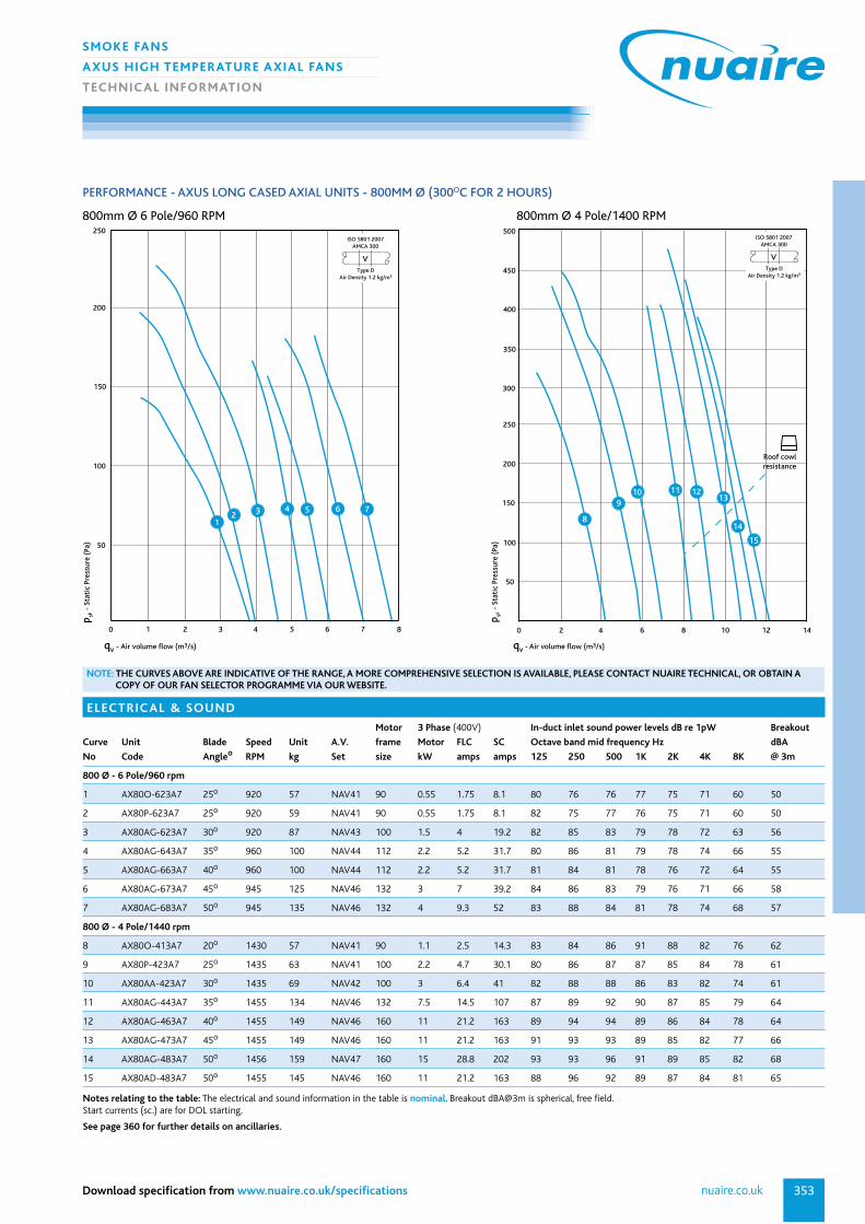
PERFORMANCE - AXUS LONG CASED AXIAL UNITS - 800MM Ø (300OC FOR 2 HOURS)
ELECTRIC AL & SOUND
Motor 3 Phase (400V) In-duct inlet sound power levels dB re 1pW Breakout
Curve Unit Blade Speed Unit A.V. frame Motor FLC SC Octave band mid frequency Hz dBA
No Code Angleo RPM kg Set size kW amps amps 125 250 500 1K 2K 4K 8K @ 3m
800 Ø - 6 Pole/960 rpm
1 AX80O-623A7 25o 920 57 NAV41 90 0.55 1.75 8.1 80 76 76 77 75 71 60 50
2 AX80P-623A7 25o 920 59 NAV41 90 0.55 1.75 8.1 82 75 77 76 75 71 60 50
3 AX80AG-623A7 30o 920 87 NAV43 100 1.5 4 19.2 82 85 83 79 78 72 63 56
4 AX80AG-643A7 35o 960 100 NAV44 112 2.2 5.2 31.7 80 86 81 79 78 74 66 55
5 AX80AG-663A7 40o 960 100 NAV44 112 2.2 5.2 31.7 81 84 81 78 76 72 64 55
6 AX80AG-673A7 45o 945 125 NAV46 132 3 7 39.2 84 86 83 79 76 71 66 58
7 AX80AG-683A7 50o 945 135 NAV46 132 4 9.3 52 83 88 84 81 78 74 68 57
800 Ø - 4 Pole/1440 rpm
8 AX80O-413A7 20o 1430 57 NAV41 90 1.1 2.5 14.3 83 84 86 91 88 82 76 62
9 AX80P-423A7 25o 1435 63 NAV41 100 2.2 4.7 30.1 80 86 87 87 85 84 78 61
10 AX80AA-423A7 30o 1435 69 NAV42 100 3 6.4 41 82 88 88 86 83 82 74 61
11 AX80AG-443A7 35o 1455 134 NAV46 132 7.5 14.5 107 87 89 92 90 87 85 79 64
12 AX80AG-463A7 40o 1455 149 NAV46 160 11 21.2 163 89 94 94 89 86 84 78 64
13 AX80AG-473A7 45o 1455 149 NAV46 160 11 21.2 163 91 93 93 89 85 82 77 66
14 AX80AG-483A7 50o 1456 159 NAV47 160 15 28.8 202 93 93 96 91 89 85 82 68
15 AX80AD-483A7 50o 1455 145 NAV46 160 11 21.2 163 88 96 92 89 87 84 81 65
Notes relating to the table: The electrical and sound information in the table is nominal. Breakout dBA@3m is spherical, free field.Start currents (sc.) are for DOL starting.
See page 360 for further details on ancillaries.
qv - Air volume flow (m3/s)
0 2 3 4 5 6 7 81
50
100
150
200
250
VType D
Air Density 1.2 kg/m3
ISO 5801 2007AMCA 300
p sF -
Sta
tic
Pres
sure
(Pa
)
12 3 4 5 6 7
0 2 4 6 8
50
100
150
200
250
300
350
400
450
500
10 12 14
qv - Air volume flow (m3/s)
p sF -
Sta
tic
Pres
sure
(Pa
)10 11 12
13
14
15
8
9
Roof cowlresistance
VType D
Air Density 1.2 kg/m3
ISO 5801 2007AMCA 300
NOTE: THE CURVES ABOVE ARE INDICATIVE OF THE RANGE, A MORE COMPREHENSIVE SELECTION IS AVAILABLE, PLEASE CONTACT NUAIRE TECHNICAL, OR OBTAIN ACOPY OF OUR FAN SELECTOR PROGRAMME VIA OUR WEBSITE.
800mm Ø 6 Pole/960 RPM 800mm Ø 4 Pole/1400 RPM

029 2085 8200354
SMOKE FANS
AXUS HIGH TEMPERATURE AXIAL FANS
TECHNIC AL INFORMATION
PERFORMANCE - AXUS LONG CASED AXIAL UNITS - 900MM Ø (300OC FOR 2 HOURS)
ELECTRIC AL & SOUND
Motor 3 Phase (400V) In-duct inlet sound power levels dB re 1pW Breakout
Curve Unit Blade Speed Unit A.V. frame Motor FLC SC Octave band mid frequency Hz dBA
No Code Angleo RPM kg Set size kW amps amps 125 250 500 1K 2K 4K 8K @ 3m
900 Ø - 6 Pole/960 rpm
1 AX90AA-623A7 30o 920 102 NAV44 100 1.5 4 19.2 85 82 80 79 79 74 61 54
2 AX90AG-643A7 35o 945 144 NAV46 132 4 9.3 52 83 90 85 83 82 78 69 60
3 AX90AG-663A7 40o 945 144 NAV46 132 4 9.3 52 84 88 84 81 80 75 68 58
4 AX90AG-673A7 45o 950 149 NAV46 132 5.5 12.7 72 88 90 87 83 79 75 69 62
5 AX90AG-683A7 50o 970 174 NAV47 160 7.5 16.1 76 87 92 88 85 82 78 72 61
900 Ø - 4 Pole/1440 rpm
6 AX90AA-423A7 30o 1455 120 NAV45 132 5.5 10.8 81 85 92 92 90 86 85 78 71
7 AX90AG-423A7 30o 1455 163 NAV47 160 11 21.2 163 90 94 96 92 89 89 81 69
8 AX90AG-443A7 35o 1456 173 NAV47 160 15 28.8 202 90 93 96 93 90 89 82 69
9 AX90AG-463A7 40o 1456 187 NAV47 180 18.5 35.2 268 92 97 97 93 90 88 82 69
10 AX90AG-473A7 45o 1456 203 NAV47 180 22 41.7 329 94 96 97 93 89 85 81 70
11 AX90AG-483A7 50o 1450 256 NAV48 200 30 56.3 372 97 97 99 95 92 88 85 71
Notes relating to the table: The electrical and sound information in the table is nominal. Breakout dBA@3m is spherical, free field.Start currents (sc.) are for DOL starting.
See page 360 for further details on ancillaries.
0 2 3 4 5 6 7 81
50
100
150
200
250
300
9 10 11 12
VType D
Air Density 1.2 kg/m3
ISO 5801 2007AMCA 300
qv - Air volume flow (m3/s)
p sF -
Sta
tic
Pres
sure
(Pa
)
1
23
4 5
Roof cowlresistance
0 4 6 8 10 12 14 162
200
300
400
500
600
100
18
qv - Air volume flow (m3/s)
p sF -
Sta
tic
Pres
sure
(Pa
)6
78 9 10
11Roof cowlresistance
VType D
Air Density 1.2 kg/m3
ISO 5801 2007AMCA 300
NOTE: THE CURVES ABOVE ARE INDICATIVE OF THE RANGE, A MORE COMPREHENSIVE SELECTION IS AVAILABLE, PLEASE CONTACT NUAIRE TECHNICAL, OR OBTAIN ACOPY OF OUR FAN SELECTOR PROGRAMME VIA OUR WEBSITE.
900mm Ø 6 Pole/960 RPM 900mm Ø 4 Pole/1400 RPM

355nuaire.co.ukDownload specification from www.nuaire.co.uk/specifications
SMOKE FANS
AXUS HIGH TEMPERATURE AXIAL FANS
TECHNIC AL INFORMATION
PERFORMANCE - AXUS LONG CASED AXIAL UNITS - 1000MM Ø (300OC FOR 2 HOURS)
ELECTRIC AL & SOUND
Motor 3 Phase (400V) In-duct inlet sound power levels dB re 1pW Breakout
Curve Unit Blade Speed Unit A.V. frame Motor FLC SC Octave band mid frequency Hz dBA
No Code Angleo RPM kg Set size kW amps amps 125 250 500 1K 2K 4K 8K @ 3m
1000 Ø - 6 Pole/960 rpm
1 AX100AD-613A7 25o 960 115 NAV45 112 2.2 5.2 31.7 83 89 94 93 85 81 67 64
2 AX100AD-623A7 30o 945 127 NAV46 132 3 7 39.2 93 88 95 95 89 83 73 66
3 AX100CX-623A7 30o 950 161 NAV47 132 5.5 12.7 72 100 94 89 82 77 74 67 63
4 AX100CX-643A7 35o 970 190 NAV47 160 7.5 16.1 76 94 89 85 80 76 77 71 60
5 AX100CX-663A7 40o 970 214 NAV47 160 11 23.3 107 95 90 87 82 78 79 74 61
6 AX100CX-673A7 45o 970 214 NAV47 160 11 23.3 107 100 91 86 83 79 78 75 62
1000 Ø - 4 Pole/1440 rpm
7 AX100AD-413A7 25o 1455 103 NAV44 132 5.5 10.8 81 84 97 94 100 96 91 86 71
8 AX100AD-423A7 25o 1455 129 NAV46 160 11 21.2 163 96 98 103 103 98 92 87 74
9 AX100CX-413A7 30o 1455 179 NAV47 160 11 21.2 163 97 96 97 93 89 88 81 69
10 AX100CX-423A7 35o 1456 187 NAV47 160 15 28.8 202 102 98 97 94 90 88 83 70
11 AX100CX-443A7 35o 1456 221 NAV47 180 22 41.7 329 100 100 98 95 91 90 87 71
12 AX100CX-463A7 40o 1460 319 NAV49 200 30 56 372 101 101 100 97 93 92 89 73
13 AX100CX-473A7 45o 1468 359 NAV49 225 37 69 433 103 101 100 98 95 95 93 73
Notes relating to the table: The electrical and sound information in the table is nominal. Breakout dBA@3m is spherical, free field.Start currents (sc.) are for DOL starting.
See page 360 for further details on ancillaries.
0 4 106 8 122 14 16
50
350
100
150
200
250
300
VType D
Air Density 1.2 kg/m3
ISO 5801 2007AMCA 300
qv - Air volume flow (m3/s)
p sF -
Sta
tic
Pres
sure
(Pa
)
12 3
45 6
Roof cowlresistance
0 105 252015
200
100
300
400
500
600
900
700
800
qv - Air volume flow (m3/s)
p sF -
Sta
tic
Pres
sure
(Pa
)7
89 10 11
12 13
Roof cowlresistance
VType D
Air Density 1.2 kg/m3
ISO 5801 2007AMCA 300
NOTE: THE CURVES ABOVE ARE INDICATIVE OF THE RANGE, A MORE COMPREHENSIVE SELECTION IS AVAILABLE, PLEASE CONTACT NUAIRE TECHNICAL, OR OBTAIN ACOPY OF OUR FAN SELECTOR PROGRAMME VIA OUR WEBSITE.
1000mm Ø 6 Pole/960 RPM 1000mm Ø 4 Pole/1400 RPM

029 2085 8200356
SMOKE FANS
AXUS HIGH TEMPERATURE AXIAL FANS
TECHNIC AL INFORMATION
PERFORMANCE - AXUS LONG CASED AXIAL UNITS - 1120MM Ø (300OC FOR 2 HOURS)
ELECTRIC AL & SOUND
Motor 3 Phase (400V) In-duct inlet sound power levels dB re 1pW Breakout
Curve Unit Blade Speed Unit A.V. frame Motor FLC SC Octave band mid frequency Hz dBA
No Code Angleo RPM kg Set size kW amps amps 125 250 500 1K 2K 4K 8K @ 3m
1120 Ø - 6 Pole/960 rpm
1 AX112CW-613A7 25o 945 196 NAV47 132 3 7 43 91 95 94 95 88 83 74 69
2 AX112CX-613A7 25o 950 212 NAV47 132 5.5 12.7 72 94 93 88 85 81 80 82 67
3 AX112CX-623A7 30o 970 228 NAV47 160 7.5 16.1 76 98 94 89 86 83 80 79 68
4 AX112CX-643A7 35o 970 252 NAV48 160 11 23.3 107 99 96 91 87 85 83 79 69
5 AX112CX-663A7 40o 970 252 NAV48 160 11 23.3 107 101 98 94 89 87 86 83 72
6 AX112CX-673A7 45o 970 293 NAV48 180 15 30.1 205 104 100 95 91 89 88 86 73
1120 Ø - 4 Pole/1440 rpm
7 AX112CW-413A7 25o 1455 222 NAV47 160 11 21.2 163 95 101 105 104 98 92 85 77
8 AX112CX-413A7 25o 1455 233 NAV47 160 15 28.8 202 98 99 99 94 92 88 93 75
9 AX112CX-423A7 30o 1455 270 NAV48 180 22 41.7 329 102 100 100 95 94 89 90 76
10 AX112CX-443A7 35o 1460 323 NAV49 200 30 56.3 372 103 102 102 96 95 92 90 77
11 AX112CX-463A7 40o 1470 369 NAV49 225 37 69 433 105 104 105 98 98 95 94 80
12 AX112CX-473A7 45o 1480 531 NAV51 250 55 101 707 108 106 106 100 100 97 97 81
Notes relating to the table: The electrical and sound information in the table is nominal. Breakout dBA@3m is spherical, free field.Start currents (sc.) are for DOL starting.
See page 360 for further details on ancillaries.
0 5 10 15 20 25
50
500
100
150
200
250
300
350
400
450
VType D
Air Density 1.2 kg/m3
ISO 5801 2007AMCA 300
qv - Air volume flow (m3/s)
p sF -
Sta
tic
Pres
sure
(Pa
)
12 3
4 5 6
Roof cowlresistance
0 10 15 20 25 305
800
1000
1200
600
400
200
35
VType D
Air Density 1.2 kg/m3
ISO 5801 2007AMCA 300
qv - Air volume flow (m3/s)
p sF -
Sta
tic
Pres
sure
(Pa
)
78 9 10 11 12
Roof cowlresistance
NOTE: THE CURVES ABOVE ARE INDICATIVE OF THE RANGE, A MORE COMPREHENSIVE SELECTION IS AVAILABLE, PLEASE CONTACT NUAIRE TECHNICAL, OR OBTAIN ACOPY OF OUR FAN SELECTOR PROGRAMME VIA OUR WEBSITE.
1120mm Ø 6 Pole/960 RPM 1120mm Ø 4 Pole/1400 RPM
357nuaire.co.ukDownload specification from www.nuaire.co.uk/specifications
SMOKE FANS
AXUS HIGH TEMPERATURE AXIAL FANS
TECHNIC AL INFORMATION
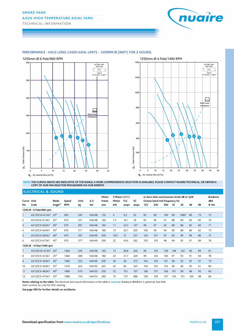
PERFORMANCE - AXUS LONG CASED AXIAL UNITS - 1250MM Ø (300OC FOR 2 HOURS)
ELECTRIC AL & SOUND
Motor 3 Phase (400V) In-duct inlet sound power levels dB re 1pW Breakout
Curve Unit Blade Speed Unit A.V. frame Motor FLC SC Octave band mid frequency Hz dBA
No Code Angleo RPM kg Set size kW amps amps 125 250 500 1K 2K 4K 8K @ 3m
1250 Ø - 6 Pole/960 rpm
1 AX125CW-613A7 25o 945 245 NAV48 132 4 9.3 52 95 99 100 99 9487 80 73 73
2 AX125CX-613A7 25o 970 257 NAV48 160 7.5 16.1 76 95 96 91 88 84 83 85 70
3 AX125CX-623A7 30o 970 281 NAV48 160 11 23.3 107 99 97 92 89 86 83 82 71
4 AX125CX-643A7 35o 970 311 NAV48 180 15 30.1 205 100 99 94 90 88 86 82 72
5 AX125CX-663A7 40o 970 347 NAV49 200 18.5 37 237 102 101 97 92 90 89 86 75
6 AX125CX-673A7 45o 970 377 NAV49 200 22 43.6 262 105 103 98 94 92 91 89 76
1250 Ø - 4 Pole/1440 rpm
7 AX125CW-413A7 25o 1460 245 NAV48 160 15 28.8 202 99 105 109 108 102 96 89 81
8 AX125CX-413A7 25o 1460 289 NAV48 180 22 41.7 329 99 102 100 97 93 91 94 78
9 AX125CX-423A7 30o 1460 353 NAV49 200 30 56 372 103 103 101 98 95 92 91 79
10 AX125CX-443A7 35o 1470 423 NAV50 225 45 83 525 104 105 103 99 96 95 91 80
11 AX125CX-463A7 40o 1480 619 NAV53 250 55 101 707 106 107 106 101 99 98 95 83
12 AX125CX-473A7 45o 1480 724 NAV54 280 75 137 986 109 109 107 103 101 100 98 84
Notes relating to the table: The electrical and sound information in the table is nominal. Breakout dBA@3m is spherical, free field.Start currents (sc.) are for DOL starting.
See page 360 for further details on ancillaries.
0 10 15 20 255
100
200
300
400
500
30
600
35
VType D
Air Density 1.2 kg/m3
ISO 5801 2007AMCA 300
qv - Air volume flow (m3/s)
p sF -
Sta
tic
Pres
sure
(Pa
)
12 3
45
6
Roof cowlresistance
0 10 15 20 25 30 35 405
800
1000
1200
1400
600
400
200
45 50
VType D
Air Density 1.2 kg/m3
ISO 5801 2007AMCA 300
qv - Air volume flow (m3/s)
p sF -
Sta
tic
Pres
sure
(Pa
)
7
8 910 11 12
Roof cowlresistance
NOTE: THE CURVES ABOVE ARE INDICATIVE OF THE RANGE, A MORE COMPREHENSIVE SELECTION IS AVAILABLE, PLEASE CONTACT NUAIRE TECHNICAL, OR OBTAIN ACOPY OF OUR FAN SELECTOR PROGRAMME VIA OUR WEBSITE.
1250mm Ø 6 Pole/960 RPM 1250mm Ø 4 Pole/1400 RPM

029 2085 8200358
SMOKE FANS
AXUS HIGH TEMPERATURE AXIAL FANS
TECHNIC AL INFORMATION
DIMENSIONS
DIMENSIONS (mm) & WEIGHTS
Max.
Weight
Code Frame A B C D E F G H J K Kg
AX31 80 315 400 365 210 270 8 12 355 220 270 23
AX35 90 350 430 380 240 270 8 12 395 250 300 26
AX40 90-100 400 490 440 270 370 8 12 450 290 340 44
AX45 90-112 450 540 450 300 360 8 12 500 330 380 65
AX45 132 450 540 600 300 520 8 12 500 330 380 65
AX50 90-112 500 608 465 340 360 12 12 560 380 430 88
AX50 132 500 608 615 340 520 12 12 560 380 430 88
AX56 90-100 560 670 440 370 360 12 12 620 420 470 104
AX56 132 560 670 615 370 520 12 12 620 420 470 104
AX63 90-112 630 740 480 430 360 12 12 690 500 550 209
AX63 132-180 630 740 600 430 520 12 12 690 500 550 209
AX63 160-180 630 740 800 430 300 12 12 690 500 550 209
AX71 80-112 710 814 455 470 360 16 12 770 540 600 124
AX71 132 710 814 700 470 620 16 12 770 540 600 124
AX80 90-112 800 910 440 540 360 16 12 860 590 650 142
AX80 132-160 800 910 840 540 620 16 12 860 590 650 142
AX90 112-180 900 1016 740 600 660 16 15 970 670 750 203
AX100 112-180 1000 1128 740 670 630 16 15 1070 770 850 324
AX100 200 1000 1128 850 740 16 15 1070 770 850 324
AX112 132-160 1120 1240 730 750 620 20 15 1190 870 950 551
AX112 180-200 1120 1240 865 750 755 20 15 1190 870 950 551
AX112 225-250 1120 1240 1010 750 900 20 15 1190 870 950 551
AX125 132-200 1250 1365 865 830 755 20 15 1320 920 1000 729
AX125 225-280 1250 1365 1010 830 900 20 15 1320 920 1000 729
Please call Nuaire on (029) 2085 8200 if you require further details.
See page 360 for further details on ancillaries.
F= No. of G dia holes equi-spacedon H p.c.d.
Unit shown supported on optional mounting brackets and A.V. mounts
OptionalAV mounts
AIRFLOW
E ctrs
D
B F
lang
e
A
C
K foot
J ctrs

359
SMOKE FANS
ANCILLARIES
TECHNIC AL INFORMATION
nuaire.co.ukDownload specification from www.nuaire.co.uk/specifications
AXUS HIGH TEMPERATURE AXIAL FANS
Ancillary Code AX31 AX35 AX40 AX45 AX50 AX56 AX63 AX71 AX80 AX90 AX100 AX112 AX125
(mm) 315 350 400 450 500 560 630 710 800 900 1000 1120 1250
Description
Mounting Mounting brackets CMB31 CMB35 CMB40 CMB45 CMB50 CMB56 CMB63 CMB71 CMB80 CMB90 CMB100 CMB112 CMB125
Brackets supplied as pair.
manufactured from
heavy gauge steel.
Matching Flange supplied as single. CMF31 CMF35 CMF40 CMF45 CMF50 CMF56 CMF63 CMF71 CMF80 CMF90 CMF100 CMF112 CMF125
Flange Manufactured from
galvanised steel.
Flexible Circular without flange. CFCH31 CFCH35 CFCH40 CFCH45 CFCH50 CFCH56 CFCH63 CFCH71 CFCH80 CFCH90 CFCH100 CFCH112 CFCH125
Connector Flexible duct material
is flameproof and heat
resistant up to 132oC.
The material is airtight
and waterproof.
Anti-vibration Resiliant rubber, for
Mounts fan only.
Attenuator Standard, Long, CA31S CA35S CA40S CA45S CA50S CA56S CA63S CA71S CA80S CA90S CA100S CA112S CA125S
podded & long CA31L CA35L CA40L CA45L CA50L CA56L CA63L CA71L CA80L CA90L CA100L CA112L CA125L
podded options. CA31P CA35P CA40P CA45P CA50P CA56P CA63P CA71P CA80P CA90P CA100P CA112P CA125P
CA31LP CA35LP CA40LP CA45LP CA50LP CA56LP CA63LP CA71LP CA80LP CA90LP CA100LP CA112LP CA125LP
Guard Manufactured in heavy CDG31 CDG35 CDG40 CDG45 CDG50 CDG56 CDG63 CDG71 CDG80 CDG90 CDG100 CDG112 CDG125
gauge galvanised steel
with acid zinc plated
steel mesh.
Inlet Cone manufactured in heavy CIC31 CIC35 CIC40 CIC45 CIC50 CIC56 CIC63 CIC71 CIC80 CIC90 CIC100 CIC112 CIC125
gauge galvanised steel
with a single bolted flange.
Backdraft Gravity operated damper CBD31 CBD35 CBD40 CBD45 CBD50 CBD56 CBD63 CBD71 CBD80 CBD90 CBD100 CBD112 CBD125
Damper manufactured from
heavy gauge galvanised
steel with pair of bolted
flanges.
Roof Cowl Manufactured from - - ARC56 ARC56 ARC71 ARC71 ARC71 ARC100 ARC100 ARC125 ARC125 ARC125 ARC125
Aluzinc designed to use with
high temperature Axial Fans.
ANCILLARIES
For further details on AV Mounts please contact Nuaire
See page 360 for further details on ancillaries.

029 2085 8200360
SMOKE FANS
ANCILLARIES
TECHNIC AL INFORMATION
ANCILLARIES FOR AXIAL FANS - DETAILS
Mounting BracketsThe AXUS mounting brackets are manufactured from heavy gaugegalvanised steel and are supplied in pairs. Typical Code: CMB100 (100 = fan diameter in cm).
Matching Flange (Single)Manufactured from galvanised steel matching flanges are suppliedindividually. Typical code: CMF100 (100 = fan diameter in cm).
Flexible Connector (Single)Circular without flanges. Flexible duct material is flameproof and resistantto heat up to 132°C/400°C, chemicals, ozone, oil and grease. The materialis airtight, waterproof and tested to BS476 Part 7.(Supplied complete with fixing straps).CFCH100 (100 = fan diameter in cm) - 400°C.
Guard (Single)Manufactured from heavy gauge galvanised steel and acid zinc plated steel mesh.Flat type • Finger guard 0.75.Typical Code: CGD100 (100 = fan diameter in cm) Pressure Drop (Pa) = 0.6 x k x Velocity (m/s).
Inlet Cone (Single)Manufactured in heavy gauge galvanised steel with a single bolted flange. Standard Accessory Losses (k).Low loss • inlet cone 0.38.Typical Code: CIC100 (100 = fan diameter in cm) Pressure Drop (Pa) = 0.6 x k x Velocity (m/s).
Backdraught Damper (Single)Gravity operated backdraught damper, manufactured from heavy gaugegalvanised steel with a pair of bolted flanges. Standard Accessory Losses (k) (Air stream operated) 0.4Typical Code: CBD100 (100 = fan diameter in cm) - 132°C (For horizontal mounting only).Pressure Drop (Pa) = 0.6 x k x Velocity (m/s).
AV Mounts Spring TypeSupplied as a set of 4.Typical Code: NAV49
H basefixing centres
G
C/L fan
AHoles matchfan flanges
B
To matchfan diameter
E
F
CD
Holes matchfan flanges

361
SMOKE FANS
ANCILLARIES
TECHNIC AL INFORMATION
nuaire.co.ukDownload specification from www.nuaire.co.uk/specifications
In-line Circular Attenuators
Standard Un-podded
PERFORMANCE, DIMENSIONS (mm) & WEIGHTS
Dynamic Attenuation
Octave band mid frequency (Hz) Dimensions & Weights
Dia. Unit Code Type 125 250 500 1K 2K 4K 8K A C D E F G Weight Kg
315mm CA31S Standard Un-podded -1 -2 -4 -7 -9 -7 -5 315 515 315 8 M8 355 8.0
350mm CA35S Standard Un-podded -1 -2 -4 -7 -9 -7 -5 355 555 355 8 M8 395 11.0
400mm CA40S Standard Un-podded -2 -3 -5 -7 -9 -6 -5 400 600 400 8 M10 450 16.0
450mm CA45S Standard Un-podded -2 -3 -6 -7 -8 -6 -5 450 650 450 8 M10 500 20.0
500mm CA50S Standard Un-podded -2 -3 -6 -8 -8 -6 -4 500 700 500 12 M10 560 23.0
560mm CA56S Standard Un-podded -2 -4 -7 -8 -8 -5 -4 560 760 560 12 M10 620 25.0
630mm CA63S Standard Un-podded -2 -4 -8 -9 -8 -5 -4 630 830 630 12 M10 690 30.0
710mm CA71S Standard Un-podded -3 -5 -8 -9 -7 -5 -4 710 910 710 16 M10 770 34.0
800mm CA80S Standard Un-podded -3 -5 -9 -8 -7 -4 -3 800 1000 800 16 M10 860 73.0
900mm CA90S Standard Un-podded -3 -6 -9 -8 -6 -4 -2 900 1100 900 16 M12 970 92.0
1000mm CA100S Standard Un-podded -3 -6 -9 -8 -6 -4 -2 1000 1200 1000 16 M12 1070 111.0
1120mm CA112S Standard Un-podded -4 -6 -9 -7 -6 -3 -2 1120 1320 1120 20 M12 1190 143.0
1250mm CA125S Standard Un-podded -4 -7 -9 -7 -5 -3 -2 1250 1450 1250 20 M12 1320 188.0
Note: Pressure drop negligible.
Long Un-podded
PERFORMANCE, DIMENSIONS (mm) & WEIGHTS
Dynamic Attenuation
Octave band mid frequency (Hz) Dimensions & Weights
Dia. Unit Code Type 125 250 500 1K 2K 4K 8K A C D E F G Weight Kg
315mm CA31L Long - Un-podded -2 -3 -6 -12 -15 -13 -9 630 515 315 8 M8 355 15.0
350mm CA35L Long - Un-podded -2 -3 -6 -12 -15 -12 -8 710 555 355 8 M8 395 21.0
400mm CA40L Long - Un-podded -3 -3 -7 -13 -14 -12 -8 800 600 400 8 M10 450 30.0
450mm CA45L Long - Un-podded -3 -4 -8 -13 -14 -11 -7 900 650 450 8 M10 500 38.0
500mm CA50L Long - Un-podded -3 -4 -10 -14 -13 -10 -7 1000 700 500 12 M10 560 42.0
560mm CA56L Long - Un-podded -3 -5 -12 -14 -13 -10 -7 1120 760 560 12 M10 620 47.0
630mm CA63L Long - Un-podded -3 -6 -13 -15 -13 -9 -6 1260 830 630 12 M10 690 56.0
710mm CA71L Long - Un-podded -4 -6 -13 -15 -12 -9 -6 1420 910 710 16 M10 770 63.0
800mm CA80L Long - Un-podded -4 -8 -14 -14 -11 -8 -5 1600 1000 800 16 M10 860 133.0
900mm CA90L Long - Un-podded -5 -10 -15 -14 -10 -6 -3 1800 1100 900 16 M12 970 166.0
1000mm CA100L Long - Un-podded -6 -11 -15 -14 -10 -6 -3 2000 1200 1000 16 M12 1070 203.0
1120mm CA112L Long - Un-podded -6 -11 -15 -13 -10 -6 -3 2240 1320 1120 20 M12 1190 261.0
1250mm CA125L Long - Un-podded -6 -12 -15 -12 -9 -5 -3 2500 1450 1250 20 M12 1320 343.0
Note: Pressure drop negligible.
C D
A'E' No. of holes tapped 'F' equi-spaced on 'G' P.C.D.
Attenuators shall be rigidly constructed from galvanised steel, internallylined with sound absorbing material not less than100mm thick retained by galvanised steel perforated sheet.
Attenuator ‘end faces’ shall be drilled and tapped to match the flangedetails of the associated fan. Attenuator ‘sound absorbing material’ shallbe chemically inert, non combustible, non-hygroscopic and verminresistant.
Attenuator shall be tested in accordance with BS4718 :1971 ASTME 477.
All attenuators shall be suitable for internal and external use at anyinstalled angle.
Standard - Typical code: CA100S.
Long - Typical code: CA100L
For podded silencer information please refer to Axial section.

029 2085 8200362
SMOKE FANS
ANCILLARIES
TECHNIC AL INFORMATION
ANCILLARIES FOR AXIAL FANS - DETAILS CONT.
Vertical Discharge Cowl
FLOW
A sq
C
A sq
B
D sqInside Skirt
DIMENSIONS (mm) & WEIGHTS
Code A B C D Max Weight Kg
ARC56 845 570 535 786 22
ARC71 1100 770 760 1045 37
ARC100 1295 1000 880 1234 79
ARC125 1795 1300 1160 1738 213
For further assistance, please contact Nuaire Technical on (029) 2085 8200.
Fans and Cowls are supplied separately.
ARC COWL
Drop-in plenum made by others
Depth confirmed by client
Matching flanges complete with flexible connector
Airflow
Anti-vibration mount
Mounting Brkt. Secondary steels by clientMatching flange complete with flexible connector
AXUS Axial Flow Fan
ARC COWL
Drop-in plenum made by others
Depth confirmed by client
Matching flanges complete with flexible connector
Airflow
Anti-vibration mount Secondary steels by client
AXUS Axial Flow Fan
Air seal Air seal
VERTICAL DISCHARGE COWL - DIMENSIONS

363
SMOKE FANS
AXUS HIGH TEMPERATURE AXIAL FANS
TECHNIC AL INFORMATION
nuaire.co.ukDownload specification from www.nuaire.co.uk/specifications
Prefabricated Curb
Builders Upstand
C & C
inside trimmer angles
A x A
D x D maximum
Flashing can be extended over curbor to underside of timber
A x A minimum dim.
Inside roof opening
B
D x D maximum
150 min
150 min
CONCRETE
ROOF
DECKING
ROOF
Trimmer
Purlin
Wood capping(optional 15mmoverhang)
Note:Wooden capping to be hardwood or treated softwood.
CURB DIMENSIONS
CURB DIMENSIONS (mm) (300 O C/400 O C UNITS)
Code A B C D
ARC56 600 75 675 746
ARC71 800 100 875 1016
ARC100 1000 100 1100 1198
ARC125 1500 100 1600 1700

029 2085 8200364
SMOKE FANS
AXUS HIGH TEMPERATURE AXIAL FANS
TECHNIC AL INFORMATION
WIRING - AXUS AXIAL FANS
2 Speed 3 phase Dual Wound Motors(D.O.L. starting both speeds)
400V 3 phase 50Hz supply
1U
1V
1W
2U
2V
2W
1U
1V
1W
2U
2V
2W
L1
L2
L3
L1
L2
L3
High speedLow speed
NOTE: If a two speed starter is used it must have TWO contactors. Individual wiring diagrams are included with each unit.
2 Speed 3 phase TAP/PAM Wound Motors(D.O.L. starting both speeds)
1U
1V
1W
2U
2V
2W
400V 3 phase 50Hz supply
Link (if no control is used)
High speedLow speed
NOTE: If a two speed starter is used it must have THREE contactors.Individual wiring diagrams are included with each unit.
L1
L2
L3
1U
1V
1W
2U
2V
2W
L1
L2
L3
Single Speed 3 Phase (Below 4kW)
L1 L2 L3
400V 3 phase 50Hz supply
Fanunit
3 phase for Star/Delta Starting (4kW and above)
U1
V1
W1
W2
U2
V2
400V 3 phase
50Hz supply
STAR
L1 - U1L2 - V1L3 - W1Link W2, U2, V2
DELTA
L1 - U1 - W2L2 - V1 - U2 L3 - W1 - V2
Note: individual wiring instructions
are included with all units.
Note: For D.O.L. (Direct On Line) operation or Inverter type Speed Controlwire in DELTA
3 Phase input Matched Nuaire Inverter Speed Control
L1 L2 L3
L1 L/L2 N/L3 PE/ W V U
400V 3 phase 50Hz supply
3 Phase onlyINVERTER SPEED CONTROL
Connectionsto motor
3 Phase input.
Motor
3 phase
Notes:Motors should be fitted with PTC Termistors. Refer to Inverter installation sheet fot instructions on connection and programming..Total length of motor leads should not exceed 50 metres.If a screened motor cable is used, maximum length should be 25 metres. Consult out Technical Department if you wish to use longer leads. Inverters are configured to suit specific fans and control applications as described on the Customer Order free of charge.
Matched Nuaire Inverter Speed Control
Important: when the unit is operated inemergency mode, smoke extract operation,all controls must be bypassed.

365
SMOKE FANS
AXUS HIGH TEMPERATURE AXIAL FANS
TECHNIC AL INFORMATION
nuaire.co.ukDownload specification from www.nuaire.co.uk/specifications
FAN SPECIFICATION - SMOKE EXTRACTThe ventilation fan Unit shall be configured and arranged as detailed on the
drawings and in accordance with the schedule of equipment and shall be of the
High Temperature AXUS axial flow fan as manufactured by Nuaire. The units
shall be manufactured heavy gauge galvanised corrosion resistant steel to BS
EN10142 1991. The case shall be fitted with an external terminal box to IP55.
The fan impeller and motor shall be direct drive with IE2 high efficiency motors
to BS5000 as standard and shall be foot mounted TENV type with IP55
enclosures and class H insulation in accordance with BS4999 part 20. The
bearing type shall either:
a) Sealed for life (below 160 frame).
b) Regreasable (160 frame and above).
Motors shall be pre-wired to an external electrical terminal box through
weatherproof flexible conduit to IP55.
The units shall be suitable for operation in ambient temperatures up to 60°C and
a one off operation of 300°C for 2 hours to class F300/120 minutes or 400°C for
2 hours to class F400/120 minutes.
The unit shall be certified to EN12101-3. The unit has been independently
tested for high temperature operation by BSRIA and certified by BSI. The unit is
suitable for operating in smoke reservoir and non smoke reservoir applications.
A two speed version of the unit to be provided where specified and controlled in
accordance with the specification and manufacturers recommendations.
The unit shall be supplied with all necessary ancillaries as recommended by the
manufacturer and in accordance with the equipment schedule.
The contractor shall allow for all necessary ductwork transformations to and
from the fan unit and any associated components in accordance with the
manufacturers recommendations, DW 144 and general good practice.
The impeller blades shall be of special aero-foil section giving excellent
performance and low noise characteristic manufactured from cast aluminium
alloy (300ºC). All units shall be suitable for internal and external operation and
can be installed any angle.
The units will be provided complete with matching flanges, flexible connections,
anti vibration mounts and all other necessary components to complete the
installation and shall be in accordance with the manufacturer’s specification.
The unit and ancillaries shall be supplied with a 3 year warranty.
The unit shall be of the High Temperature AXUS type as manufactured by
Nuaire Ltd.
CONSULTANTS SPECIFICATION

029 2085 8200366
SMOKE FANS
SQUIF HIGH TEMPERATURE
TECHNIC AL INFORMATION
SQUIF HIGH TEMPERATURE FANS
HIGH TEMPERATURE CENTRIFUGAL SQUIF FOR SMOKE EXTRACT
CERTIFIED TO EN12101-3-2002.

367
SMOKE FANS
SQUIF HIGH TEMPERATURE
TECHNIC AL INFORMATION
nuaire.co.ukDownload specification from www.nuaire.co.uk/specifications
HIGH TEMPERATURE APPLICATION Capable of running continuously at 90ºC, ideal for
kitchen canopy applications with a one off 400ºC
for 2 hours.
QUIET OPERATION One of the quietest solutions for motor unit out of
airstream applications.
EASY MAINTENANCE ‘Out of air stream’ allows for quick and easy access
and lower maintenance costs.
IDEAL FOR HIGH RESISTANCES High pressure development suitable for ducted
systems.
FLEXIBLE SOLUTION Can be mounted internally, externally, vertically or
horizontally.
FAN TO SUIT ALL APPLICATIONS2-speed motors available for day to day extract and
smoke extract.
SAFETY TESTED Fans are tested to comply to EN12101-3 2002.
WARRANTY High temperature Squif has a 3 year warranty.
Note: only suitable for outside smoke reservoir
applications.
BENEFITS
SQUIF ANCILLARIES
Splitter Attenuator. AV Mounts. Flexible Connector.
Feet built in. Guard for square units.
Electronic Speed Control.
Transformer Speed Control.
CONTROLS
Inverter Speed Control.

029 2085 8200368
SMOKE FANS
SQUIF HIGH TEMPERATURE
TECHNIC AL INFORMATION
Fan
Stat
ic P
ress
ure
(Pa)
Fan
Stat
ic P
ress
ure
(Pa)
7
Squif - 4 pole
400
800
1200
1600
2000
Air volume flow rate (m /s)3
Squif - 6 pole
200
400
600
800
1000
0 1.0 2.0 3.0 4.0 5.0 6.0
7
10
9
0 1.0 2.0 3.0 4.0 5.0 6.0 7.0
2
1
3 4
6
5
0
0
8
Air volume flow rate (m /s)3
VType D
Air Density 1.2 kg/m3
ISO 5801 2007AMCA 300
VType D
Air Density 1.2 kg/m3
ISO 5801 2007AMCA 300
PERFORMANCE - SQUIF HIGH TEMPERATURE FANS Casing
SQF 4 1 - 3 | | | |1 2 3 4
1. Squif range
2. Pole (4 or 6)
3. Curve No.
4. Phase (1 or 3)
Code descriptions

369
SMOKE FANS
SQUIF HIGH TEMPERATURE
TECHNIC AL INFORMATION
nuaire.co.ukDownload specification from www.nuaire.co.uk/specifications
QUICK SELECTION GUIDE
SQUIF HIGH TEMPERATURE
Fan unit Standard Long Flexible Fan AV
silencers silencers Connectors Guards Mounts
SQF41-3 SQFS1S SQFS1L SQFF1 SQFGD1 NAV2
SQF41-1 SQFS1S SQFS1L SQFF1 SQFGD1 NAV2
SQF42-3 SQFS2S SQFS2L SQFF2 SQFGD2 NAV2
SQF43-3 SQFS3S SQFS3L SQFF3 SQFGD3 NAV2
SQF43-1 SQFS3S SQFS3L SQFF3 SQFGD3 NAV2
SQF44 SQFS4S SQFS4L SQFF4 SQFGD4 NAV5
SQF45 SQFS4S SQFS4L SQFF5 SQFGD5 NAV5
SQF46 SQFS5S SQFS5L SQFF6 SQFGD6 NAV3
SQF61 SQFS5S SQFS5L SQFF4 SQFGD4 NAV3
SQF62 SQFS6S SQFS6L SQFF5 SQFGD5 NAV4
SQF63 SQFS7S SQFS7L SQFF6 SQFGD6 NAV4
SQF64 SQFS8S SQFS8L SQFF7 SQFGD7 NAV6
SQUIF
ELECTRIC AL & SOUND
Motor Sound Power Levels (dB re 1pW)
Power FLC SC SC Data Octave band mid frequency (Hz) dBA
Curve Code Phase RPM (kW) (amps) (amps) ★/▲ Type 125 250 500 1K 2K 4K 8K @ 3m
1 SQF 41-3 3 1450 0.37 1.1 5.2 - I 90 79 70 70 70 69 62 50
SQF 41-1 1 1410 0.37 2.8 11.2 O 91 74 68 74 75 70 64
2 SQF 42-3 3 1450 0.75 2 9.0 - I 92 82 77 74 76 75 67 53
3 SQF 43-3 3 1450 1.1 2.5 12 - I 95 83 79 77 78 78 71 56
SQF 43-1 1 1420 1.1 7 35 O 96 79 77 82 83 79 73
4 SQF 44 3 1450 2.2 4.8 12 - I 93 89 82 77 80 80 71 58
O 87 86 87 81 82 82 68
5 SQF 45 3 1450 4 8.3 45 15 I 99 87 85 85 84 83 81 62
O 100 83 82 89 89 84 83
6 SQF 46 3 1450 7.5 15.2 108 36 I 103 92 86 86 85 86 83 63
O 92 90 91 89 87 87 81
7 SQF 61 3 960 0.75 2.1 8.82 - I 89 84 75 70 73 73 64 47
O 83 81 80 74 75 75 61
8 SQF 62 3 960 1.1 3 13.2 - 96 83 78 76 75 74 72 56
O 97 78 76 80 79 75 74
9 SQF 63 3 960 2.2 5.9 28.9 - I 100 87 79 76 76 77 73 59
O 101 82 77 80 80 78 75
10 SQF 64 3 960 4 9.4 63 20.4 I 103 91 82 79 77 77 74 62
O 104 86 80 83 82 78 76
The electrical and sound information in the table is nominal. Breakout dBA@3m is spherical, free field.Start currents (sc) are DOL 1 = 1 phase (230 Volt, 50Hz) 3 = 3 phase (400 Volt, 50Hz).SC★/▲ = star delta starting current.

029 2085 8200370
SMOKE FANS
SQUIF HIGH TEMPERATURE
TECHNIC AL INFORMATION
DOUBLE FLANGED FLEXIBLE CONNECTOR
Flexible duct material is flame proof. Heat resistance is 400°C with excellent resistance tochemicals, ozone, oil and grease. The connector is air-tight, waterproof and tested to BS476Part 7.
Dimensions (mm)
Code Squif Fan A B C F E
SQFF 1 SQF41-3 150 560 560 532 532
SQF41-1
SQFF 2 SQF42-3 150 760 660 730 630
SQFF 3 SQF43-3 150 810 710 780 680
SQF43-1
SQFF 4 SQF44 150 860 760 830 730
SQF61
SQFF 5 SQF45 150 980 880 930 830
SQF62
SQFF 6 SQF46 150 1080 980 1030 930
SQF63
SQFF 7 SQF64 150 1180 1080 1130 1030
Fctrs
C
A B
Ectrs
16 flange holes11mm dia (2 planes equi-spaced)
ANCILLARIES FOR SQUIF UNITS
GUARD FOR SQUARE FANS
Manufactured from galvanised steel wire or polyester coated mild steel. Resistance to airflow is negligible.
Dimensions (mm)
Code Squif Fan A B C
SQFGD 1 SQF41-3 532 532 11
SQF41-1
SQFGD 2 SQF42-3 730 630 13
SQFGD 3 SQF43-3 780 680 13
SQF43-3
SQFGD 4 SQF44 830 730 13
SQF61
SQFGD 5 SQF45 930 830 13
SQF62
SQFGD 6 SQF46 1030 930 13
SQF63
SQFGD 7 SQF64 1130 1030 13
For details on Melinex silencer’s please contact Nuaire.
A
4 holes C dia
B
DIMENSIONS
SQUIF DIMENSIONS (mm) & WEIGHTS
Weight
Unit size A B C D E F G H M (Kg)
SQF 41-3 634 500 500 532 532 26.5 273 227 193 52
SQF 41-1 634 500 500 532 532 26.5 273 227 193 52
SQF 42-3 692 700 600 730 630 32 382 318 215 60
SQF 43-3 750 750 650 780 680 32 412 338 231 70
SQF 43-1 750 750 650 780 680 32 412 338 231 70
SQF 44 820 800 700 830 730 32 440 360 290 100
SQF 61 820 800 700 830 730 32 440 360 290 100
SQF 45 901 900 800 930 830 32 490 410 290 150
SQF 62 901 900 800 930 830 32 490 410 290 150
SQF 46 994 1000 900 1030 930 32 546 454 387 255
SQF 63 994 1000 900 1030 930 32 546 454 387 255
SQF 64 1114 1100 1000 1130 1030 32 600 500 387 315
FLOW
FLOWView A
View B
A
Binside
Dctrs
Ectrs
H
G
Cinside
FLOW
FLOW
B inside
D ctrs
C inside
16 flange holes11mm dia.(2 planes equi-spaced)
E ctrs
A
F
HG
M
View A View B

371
SMOKE FANS
SQUIF HIGH TEMPERATURE
TECHNIC AL INFORMATION
nuaire.co.ukDownload specification from www.nuaire.co.uk/specifications
LONG SILENCERS DIMENSIONS (mm) & WEIGHTS
Matching Attenuator Airflow Dynamic insertion loss (db) Dimensions
Unit Code m3/s 125 250 500 1K 2K 4K 8K A B C D E F G Weight Kg Z
SQF 41-3 SQFS1L 0-1.1 -8 -12 -32 -42 -33 -32 -18 1200 560 560 532 532 26.5 11 38 36.8
SQF 41-1 SQFS1L 0-1.1 -8 -12 -32 -42 -33 -32 -18 1200 560 560 532 532 26.5 11 38 36.8
SQF 42-3 SQFS2L 0-1.6 -8 -12 -32 -42 -33 -32 -18 1200 760 660 630 730 32 11 43 30.5
SQF 43-3 SQFS3L 0-2.2 -8 -12 -32 -42 -33 -32 -18 1200 810 710 680 780 32 11 46 30.5
SQF 43-1 SQFS3L 0-2.2 -8 -12 -32 -42 -33 -32 -18 1200 810 710 680 780 32 11 46 30.5
SQF 44 SQFS4L 0-3.1 -8 -12 -32 -42 -33 -32 -18 1200 860 760 730 830 32 11 60 10.9
SQF 61 SQFS4L 0-1.9 -8 -12 -32 -42 -33 -32 -18 1200 860 760 730 830 32 11 60 10.9
SQF 45 SQFS5L 0-4.3 -8 -12 -32 -42 -33 -32 -18 1200 980 880 830 930 32 12.5 91 5.47
SQF 62 SQFS5L 0-2.7 -8 -12 -32 -42 -33 -32 -18 1200 980 880 830 930 32 12.5 91 5.47
SQF 46 SQFS6L 0-6.5 -8 -12 -32 -42 -33 -32 -18 1200 1080 980 930 1030 32 12.5 98 5.47
SQF 63 SQFS7L 0-4.2 -8 -12 -32 -42 -33 -32 -18 1200 1080 980 930 1030 32 12.5 116 1.54
SQF 64 SQFS8L 0-6 -8 -12 -32 -42 -33 -32 -18 1200 1180 1080 1030 1130 32 12.5 122 1.54
SHORT SILENCERS DIMENSIONS (mm) & WEIGHTS
Matching Attenuator Airflow Dynamic insertion loss (db) Dimensions
Unit Code m3/s 125 250 500 1K 2K 4K 8K A B C D E F G Weight Kg Z
SQF 41-3 SQFS1S 0-1.1 -4 -8 -18 -24 -19 -16 -11 900 560 560 532 532 26.5 11 15 36.8
SQF 41-1 SQFS1S 0-1.1 -4 -8 -18 -24 -19 -16 -11 900 560 560 532 532 26.5 11 15 36.8
SQF 42-3 SQFS2S 0-1.6 -4 -8 -18 -24 -19 -16 -11 900 760 660 630 730 32 11 29 30.5
SQF 43-3 SQFS3S 0-2.2 -4 -8 -18 -24 -19 -16 -11 900 810 710 680 780 32 11 32 30.5
SQF 43-1 SQFS3S 0-2.2 -4 -8 -18 -24 -19 -16 -11 900 810 710 680 780 32 11 32 30.5
SQF 44 SQFS4S 0-3.1 -4 -8 -18 -24 -19 -16 -11 900 860 760 730 830 32 11 42 10.9
SQF 61 SQFS4S 0-1.9 -4 -8 -18 -24 -19 -16 -11 900 860 760 730 830 32 11 42 10.9
SQF 45 SQFS5S 0-4.3 -4 -8 -18 -24 -19 -16 -11 900 980 880 830 930 32 12.5 61 5.47
SQF 62 SQFS5S 0-2.7 -4 -8 -18 -24 -19 -16 -11 900 980 880 830 930 32 12.5 61 5.47
SQF 46 SQFS6S 0-6.5 -4 -8 -18 -24 -19 -16 -11 900 1080 980 930 1030 32 12.5 68 5.47
SQF 63 SQFS7S 0-4.2 -4 -8 -18 -24 -19 -16 -11 900 1080 980 930 1030 32 12.5 81 1.54
SQF 64 SQFS8S 0-6 -4 -8 -18 -24 -19 -16 -11 900 1180 1080 1030 1130 32 12.5 86 1.54
Note: Air Pressure Drop of Attenuator (Pa) = Z x Q2 where Z = Factor listed in table above Q = Air Volume Flow Rate (m3/s).
ANCILLARIES FOR SQUIF HIGH TEMPERATURE UNITS CONT.
C
B
16 flange holes G Dia.
D ctrs
F Flange width
A
E ctrs
Silencers
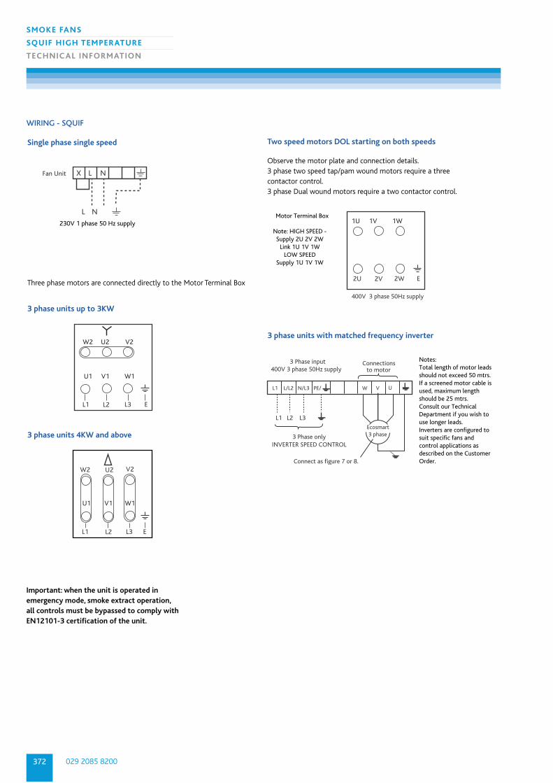
029 2085 8200372
SMOKE FANS
SQUIF HIGH TEMPERATURE
TECHNIC AL INFORMATION
WIRING - SQUIF
Single phase single speed
Fan Unit
L N
230V 1 phase 50 Hz supply
X L N
3 phase units up to 3KW
U1 V1 W1
L1 L2 L3 E
W2 U2 V2
3 phase units 4KW and above
W2
L1
U2
L2
V2
L3 E
U1 V1 W1
Two speed motors DOL starting on both speeds
1U 1V 1W
2U 2V 2W E
400V 3 phase 50Hz supply
Motor Terminal Box
Note: HIGH SPEED -Supply 2U 2V 2W
Link 1U 1V 1WLOW SPEED
Supply 1U 1V 1W
Three phase motors are connected directly to the Motor Terminal Box
Observe the motor plate and connection details.3 phase two speed tap/pam wound motors require a three contactor control.3 phase Dual wound motors require a two contactor control.
3 phase units with matched frequency inverter
L1 L2 L3
L1 L/L2 N/L3 PE/ W V U
400V 3 phase 50Hz supply
3 Phase onlyINVERTER SPEED CONTROL
Connect as figure 7 or 8.
Connectionsto motor
3 Phase input
Ecosmart3 phase
Notes:Total length of motor leadsshould not exceed 50 mtrs.If a screened motor cable isused, maximum lengthshould be 25 mtrs.Consult our TechnicalDepartment if you wish touse longer leads.Inverters are configured tosuit specific fans andcontrol applications asdescribed on the CustomerOrder.
Important: when the unit is operated inemergency mode, smoke extract operation,all controls must be bypassed to comply withEN12101-3 certification of the unit.

373
SMOKE FANS
SQUIF HIGH TEMPERATURE
TECHNIC AL INFORMATION
nuaire.co.ukDownload specification from www.nuaire.co.uk/specifications
SYSTEM SPECIFICATIONThe SMOKE EXTRACT fan Unit shall be configured and arranged as detailed on
the drawings and in accordance with the schedule of equipment and shall be of
the SQUIF type as manufactured by Nuaire. The units shall be manufactured in
heavy gauge Aluzinc corrosion resistant steel. The general construction is to class
A leakage.
The fan impeller and motor shall be selected to provide the most energy
efficient solution conforming to part L regulations and shall be direct drive with
IE2 high efficiency motors to BS5000 as standard.
The fan impeller shall be a high efficiency backward curved centrifugal design,
manufactured in galvanised steel and the motor shall be positioned outside the
ventilation airflow path. It shall provide excellent in duct and breakout noise levels.
The unit shall be capable of continuous operation at 90°C and a one off
operation at up to 400°C for a period of 2 hrs certified to EN12101-3. The unit
has been independently tested for high temperature operation by BSRIA and
certified by BSI. This shall be achieved using a standard non temperature rated
motor. The unit is only suitable for non-smoke reservoir applications.
A two speed version of the unit to be provided where specified and controlled in
accordance with the specification and manufacturers recommendations.
The unit shall be supplied with all necessary ancillaries as recommended by the
manufacturer and in accordance with the equipment schedule.
The contractor shall allow for all necessary ductwork transformations to and
from the fan unit and any associated components in accordance with the
manufacturers recommendations, DW144 and general good practice.
The unit and ancillaries shall be supplied with a 3 year warranty.
The unit shall be of the SQUIF type as manufactured by Nuaire Ltd.
CONSULTANTS SPECIFICATION

029 2085 8200374
SMOKE FANS
TWIN SQUIF
TECHNIC AL INFORMATION
HIGH TEMPERATURE TWIN SQUIF FANS
HIGH TEMPERATURE TWIN SQUIF FOR SMOKE EXTRACT
CERTIFIED TO EN12101-3-2002.

375
SMOKE FANS
TWIN SQUIF
TECHNIC AL INFORMATION
nuaire.co.ukDownload specification from www.nuaire.co.uk/specifications
QUIET AND POWERFUL SOLUTIONSHigh performance centrifugal motor/impeller
combination providing a low noise solution.
CLEANER ‘Out of air stream’ motors are ideal for dirty extract
and greasy environments. Cleaner motor improves
cooling and extends motor life.
HIGH TEMPERATURE APPLICATIONCapable of running continuously at 90ºC. Ideal for
kitchen canopy applications with a one off 400ºC
for 2 hours.
EASY MAINTENANCE‘Out of air stream’ motors allow for quick and easy
access. Inspection hatches allow the internal parts
to be easily checked and cleaned.
IDEAL FOR HIGH RESISTANCESHigh efficiency centrifugal impellers provide high
pressure development suitable for ducted systems
and kitchen canopy with extreme filtration.
PREVENTS INTERNAL RECIRCULATIONBackdraft dampers inbuilt.
FLEXIBLE SOLUTIONCan be mounted internally, externally, vertically or
horizontally. Mounting facilities included.
FAILURE DETECTIONInverter detects fan failure and Ecosmart control
sends signal to 2nd fan.
CONTROL BY OTHERS
FAN TO SUIT ALL APPLICATIONS2-speed motors available for day to day extract.
WARRANTYTwin Squif has a 3 year warranty.
Note: Please contact Nuaire for high temperature
enquiries.
Note: For information on Gas Interlock please refer
to Single Fan section.
BENEFITS
TYPICAL INSTALLATIONS
FLOW
FLOWMounting feet (supplied).
Support beamAV Mounts
Flexible connector
Dampers
AV mounts fitted to unit mounting feet (supplied)in horizontal discharge mode.
Unit in vertical discharge mode, mounted on supportbeam using AV mounts.

029 2085 8200376
SMOKE FANS
TWIN SQUIF
TECHNIC AL INFORMATION
PERFORMANCE - HIGH TEMPERATURE TWIN SQUIF FANS Casing
Fan
Stat
ic P
ress
ure
(Pa)
Twin Squif - 4 pole
200
400
600
800
2000
Air volume flow rate (m /s)3
0 1.0 2.0 3.0 4.0 5.0 6.0 7.0
2
1
3 4
0
1000
1200
1400
1600
1800
2200
5
6
VType D
Air Density 1.2 kg/m3
ISO 5801 2007AMCA 300
SQFT 4 1 - 3
| | | |1 2 3 4
1. High Temperature Twin Squif
2. Pole (4 or 6)
3. Curve No.
4. Phase (1 or 3)
Note: curves include loss through idling fan.
Code descriptions
PERFORMANCE - TWIN SQUIF EXTRACT FANS
ELECTRIC AL & SOUND
Motor Induct inlet Sound Power levels dB re lpW
Power FLC SC Data Breakout
Curve Code Phase RPM (kW) (amps) (amps) Type 63 125 250 500 1K 2K 4K 8K dBA@ 3m
1 SQFT41-1 1 1410 0.37 2.8 11.2 I 90 93 79 70 70 70 69 62 52
O 87 94 74 68 74 75 70 641 SQFT41-3 3 1450 0.37 1.06 5.2 I 90 93 79 70 70 70 69 62 52
O 87 94 74 68 74 75 70 64
2 SQFT42-3 3 1450 0.75 2.01 9.04 I 88 95 82 77 74 76 75 67 55O 85 96 78 74 78 80 77 69
3 SQFT43-1 1 1420 1.1 7 35 I 92 98 83 79 77 78 78 71 58O 89 99 79 77 82 83 79 73
3 SQFT43-3 3 1450 1.1 2.5 12 I 92 98 83 79 77 78 78 71 58O 89 99 79 77 82 83 79 73
4 SQFT44 3 1450 2.2 4.8 28.8 I 86 96 89 82 77 80 80 71 58O 87 90 86 87 81 82 82 68
5 SQFT45 3 1450 4 9 59 I 92 102 87 85 85 84 83 81 63O 90 103 83 82 89 89 84 83
6 SQFT46 3 1450 7.5 15.2 108 I 92 106 92 86 86 85 86 83 64O 95 95 90 91 89 87 87 81
7 SQFT61 3 960 0.75 2.1 8.82 I 84 92 84 75 70 73 73 64 48O 85 86 81 80 74 75 75 61
8 SQFT62 3 960 1.1 3 13.2 I 90 99 83 78 76 75 74 72 58O 87 100 78 76 80 79 75 74
9 SQFT63 3 960 2.2 5.9 28.9 I 90 103 87 79 76 76 77 73 61O 87 104 82 77 80 80 78 75
10 SQFT64 3 960 4 9.4 61.2 I 91 106 91 82 79 77 77 74 64O 88 107 86 80 83 82 78 76
Fan
Stat
ic P
ress
ure
(Pa)
Twin Squif - 6 pole
200
400
600
800
1000
0 1.0 2.0 3.0 4.0 5.0 6.0
Air volume flow rate (m /s)3
8
7
10
9
0
100
300
500
700
900
1100
VType D
Air Density 1.2 kg/m3
ISO 5801 2007AMCA 300
Breakout dBA@3m is hemispherical free field. The electrical and sound information in the table are nominal figures.

377
SMOKE FANS
TWIN SQUIF
TECHNIC AL INFORMATION
nuaire.co.ukDownload specification from www.nuaire.co.uk/specifications
DIMENSIONS - TWIN SQUIF FANS
DIMENSIONS (mm) & WEIGHT
Unit Size A B C D E F G H Motor Total Fan AV selection Mounting
(kW) Weight (Kg) Orientation
SQFT41-3 634 500 710 529 741 26.5 223.5 1110 0.37 52 NAV2
SQFT41-1 634 500 710 529 741 26.5 223.5 1110 0.37 52 NAV2
SQFT41-3ES 634 500 710 529 741 26.5 223.5 1110 0.37 80 NAV2
SQFT42-3 692 700 780 730 811 32 248 1220 0.75 77 NAV2
SQFT42-3ES 692 700 780 730 811 32 248 1220 0.75 77 NAV3
SQFT43-3 750 750 882 780 913 32 278 1382 11 102 NAV5
SQFT43-1 750 750 882 780 913 32 278 1382 11 102 NAV5
SQFT43-3ES 750 750 882 780 913 32 278 1382 11 102 NAV5
SQFT44 820 800 970 830 1001 32 303 1550 2.2 100 NAV5
SQFT61 820 800 970 830 1001 32 303 1550 0.75 111 NAV5
SQFT44ES 820 800 970 830 1001 32 303 1550 2.2 100 NAV5
SQFT61ES 820 800 970 830 1001 32 303 1550 0.75 111 NAV5
SQFT45 901 900 1075 930 1106.5 32 333 1655 4.0 150 NAV3
SQFT62 901 900 1075 930 1106.5 32 333 1655 1.1 141 NAV3
SQFT45ES 901 900 1075 930 1106.5 32 333 1655 4.0 150 NAV3
SQFT62ES 901 900 1075 930 1106.5 32 333 2070 1.1 141 NAV3
SQFT46 994 1000 1230 1030 1261 32 383 2070 7.5 315 NAV6
SQFT63 994 1000 1230 1030 1261 32 383 2070 2.2 180 NAV3
SQFT46ES 994 1000 1230 1030 1261 32 383 2070 7.5 315 NAV6
SQFT63ES 994 1000 1230 1030 1261 32 383 2070 2.2 180 NAV3
SQFT64 1114 1100 1380 1130 1411 32 433 2220 4.0 580 NAV52
SQFT64ES 1114 1100 1380 1130 1411 32 433 2220 4.0 580 NAV52
View A
View B
Binside
Dctrs
Ectrs
Cinside
A
View A
E ctrs
C inside
F
C
H
B in
side
D c
trs
H (max)
FLOWView B
FLOW FLOWG
Horizontal
discharge or
vertically
up
discharge.
Horizontal
discharge
only.

029 2085 8200378
SMOKE FANS
TWIN SQUIF
TECHNIC AL INFORMATION
WIRING - TWIN SQUIF FANS
Fan 1
L N
230V 1 phase 50 Hz Mains supply via local isolator (not shown)
X L N
Fan 2
X L N
Single Phase Fans - Constant Speed
Auto change-over control (by others)
Three phase fans Single speed - motors up to 3kW inclusive
W1 V1 U1
W2 V2 U2
Fan 1 Fan 2
W1 V1 U1
W2 V2 U2
L1 L2 L3
Auto change-over control (by others)
400V 3 phase 50 Hz supply Mains supply via local isolator (not shown)
Fan 1 Fan 2
L1 L2 L3
Auto change-over control withsoft-startercontrol (by others)
400V 3 phase 50 Hz supply Mains supply via local isolator (not shown)
Single speed - motors 4kW or above
Soft Starter
W1 V1 U1
W2 V2 U2
W1 V1 U1
W2 V2 U2

379
SMOKE FANS
TWIN SQUIF
TECHNIC AL INFORMATION
nuaire.co.ukDownload specification from www.nuaire.co.uk/specifications
SYSTEM SPECIFICATION The ventilation fan Unit shall be configured and arranged as detailed on the
drawings and in accordance with the schedule of equipment and shall be of the
SQUIF type as manufactured by Nuaire. The units shall be manufactured heavy
gauge Aluzinc corrosion resistant steel.
The general construction is to class A leakage.
FAN SPECIFICATIONThe fan impeller and motor shall be selected to provide the most energy efficient
solution conforming to part L regulations and shall be direct drive with IE2 high
efficiency motors to BS5000 as standard. The fan impeller shall be a high efficiency
backward curved centrifugal design, manufactured in galvanised steel and the
motor shall be positioned outside the ventilation airflow path.
The unit shall be capable of continuous operation at 90ºC and a one off
operation at up to 400ºC for a period of 2 hrs certified to EN12101-3. The unit
has been independently tested for high temperature operation by BSRIA and
certified by BSI. This shall be achieved using a standard non-temperature rated
motor. The unit is suitable for non-smoke reservoir applications.
Run and standby fan assemblies to incorporate fan impeller and motors selected
to provide the most energy efficient solution conforming to part L regulations and
shall be direct with IE2 high efficiency motors to EN60034-30 as standard, belt or
direct drive with EN60034-30 motors fitted with "hall effect" air flow failure
monitoring, units suitable for operation in ambient temperatures of 40ºC.
The contractor shall allow for all necessary ductwork transformations to and
from the fan unit and any associated components in accordance with the
manufacturers recommendations, DW 144 and general good practice.
The unit and ancillaries shall be of the SQFT type as manufactured by Nuaire Ltd.
CONTROLAuto change over and emergency operation controlled by others.
All equipment shall be as manufactured by Nuaire Ltd.
CONSULTANTS SPECIFICATION

029 2085 8200380
Nuaire is the clear market leader in energy-efficientcommercial, residential and renewable solutions. So if you’re designing for the top of tall buildings or the depths of basement car parks,
it’s clear Nuaire can provide the perfect ventilation solution.
Now that’s ventilation on all levels!
Detailed product information is available in our separate Residential catalogue.
Alternatively call us on 02920 858200 or visit nuaire.co.uk/residential
“Ventilation on all levels.”
SMOKE DESIGN AND EXTRACT FOR CAR PARKS
HEAT RECOVERY UNITS FOR APARTMENTS
From Penthouse Apartments
To Basement Car Parks
A selection ofour Residentialproducts…
MRXBOX95 Cupboard mounted heat recovery unitsA compact cupboard mounted ventilationsolution that is 95% efficient, SAP compliant,easy to install and simple maintenance.
MRXBOX95-WH1Heat recovery units for larger apartmentsCupboard mounted unit, 96% efficient andin the highest efficiency category in SAP. This unit comes with easy access filters formaintenance.
LPXBOX Low profile heat recovery unitsVery low depth ceiling void mountedventilation solution, SAP compliant, withlow noise and high efficiency.
OTHER RANGES INCLUDE• AC and DC bathroom and kitchen fans• Positive Input Ventilation solutions• Sunwarm Air – a unique solar thermalsolution for new build