“smnpo - engineering” jsc at a glance
TRANSCRIPT


“SMNPO - Engineering” JSC, founded in 1896, is among eastern Europe's largest machine-building enterprises focesed on manufacturing of equipment and providing integral solutions for oil, gas, chemical, petrochemical and power industries.
Product list of the company includes but is not limited to unique types of compressor equipment, pumps, centrifuges, gas ball valves, tanks, pressure vessels, mass- and heat exchangers as well as packaged facilities, namely: gas treatment units (drying, H2S removal, fractioning etc), compressor stations, fuel gas skids and other products individually designed, fabricated and tested according to specific project requirements.
Products diversity owes to company's advanced engineering and manufacturing capabilities. Facilities incorporate dedicated yards equipped with the most advanced equipment and cutting edge quality control facilities. Testing facilities comply with the strictest requirements to materials testing, product performance, acceptance and full scale tests of the manufactured products.
High quality of the products is ensured by means of qualityassurance and control system that fully complies with international standard ISO 9001. All products comply with the requirements of domestic and international standards.
Products and solutions for chemical, petrochemical oil & gas industry is one of the key expertise of “SMNPO - Engineering” JSC.
Equipment produced by the company operates at almost all chemical plants in CIS countries.
Heat exchangers were supplied for process lines of concentrated nitric acid, distillate, oil and gas refineries.
In recent years heat exchangers were supplied to the following chemical plants: GrodnoAzot JSC (Belarus), Alvigo JSC (Lithuania), Shchekinoazot JSC (Russia), oil and gas refineries of Surgutneftegaz JSC (Russia), CS Astara (Azerbaijan), BCS Zevardy, BCS Gazli (Uzbekistan), BCS Naiyp (Turkmenistan), etc.
1 “SMNPO - Engineering” JSC at a Glance
Heat Exchagers

Technical Catalogue
1. Spiral heat exchangers 5
2. Wound heat exchangers 11
3. Shell and tube heat exchangers with floating head, shell and tubes heat exchangers with U-shaped tubes and tube bundles to them as per TU 3612-023-00220302-01 14
TPV and KhPV types heat exchangers with 3000 mm tubes length 22
KP type heat exchangers 23
TU type heat exchangers 25
Heat exchange surface of TP and KhP type heat exchangers 27
Heat exchange surface of KP type heat exchangers 28
Heat exchange surface of TU type heat exchangers 29
Materials for heat exchangers manufacturing 30
Weight of TP type heat exchangers 31
Weight of KhP type heat exchangers 35
Weight of KP type heat exchangers 39
Weight of TU type heat exchangers 41
Layout of foundation bolts holes in supports 42
Tube bundle of ТP, KhP type heat echangers 43
Basic dimensions of tube bundles of TP and KhP type heat exchangers 44
Tube bundle of KP type heat echangers 46
Tube bundle of ТU type heat echangers
Basic dimensions of tube bundles of TU type heat exchangers 48
Weight of tube bundles for TP and KhP types heat exchangers at tubes holes layout at squares apexes 50
Weight of tube bundles for TP and KhP types heat exchangers at tubes holes layout at equilateral triangles corners 53
Weight of tube bundles for KP type heat exchangers at tubes holes layout at equilateral triangles corners 56
Weight of tube bundles for TU type heat exchangers at tubes holes layout at equilateral triangles corners 58
Order form for heat exchanger or tube bundle manufacturing 60
МО-53-4 type oil coolers 61
Materials for oil oolers assembly units and components manufacturing 62
4. Shell and tube heat exchangers with fixed sheets and shell and tube heat exchangers with expansion pipe on shell as to Specification TU 3612-024-002203002-2 63
TNG, TKG, KhNG, KhKG types one pass through tubes heat exchangers 66
TNV, TKV, KhKV types one pass through tubes heat exchangers 67
TNG, TKG types multi-pass through tubes heat exchangers 68
TNV, TKV types multi-pass through tubes heat exchangers 69
Basic parameters of TN and TK types heat exchangers 70
KhNG, KhKG types multi-pass through tubes heat exchangers 74
KhNV, KhKV types multi-pass through tubes heat exchangers 75
Basic parameters of KhN and KhK types heat exchangers 76
KNG, KKG types multi-pass through tubes heat exchangers 79
KNV, KKV types Multi-pass through tubes heat exchangers 80
Basic parameters of KN and KK types heat exchangers 81
IN-1, IК-1 types heat exchangers 83
Content 2
IN-2, IК-2 heat exchangers 84
Basic parameters of IN and IK heat exchangers 85
Heat-exchange surface of TN, TK, KhN, KhK heat exchangers 87
Heat-exchange surface of KN and KK heat exchangers 89
Heat-exchange surface of IN and IK heat exchangers 91
Materials for heat exchangers manufacturing 93
Weight of TN, TK heat exchangers 95
Weight of KhK, KhN heat exchangers 99
Weight of KN, KK heat exchangers 102
Weight of IN, IK heat exchangers 105
Layout of Bolt Holes in Supports in ТN, ТК, KhN, KhK, КN, КК, IN, IК Heat Exchangers 106
Layout of Supports and Nozzles in ТN, ТК, KhN, KhК, КN, КК, IN, IК Heat Exchangers 107
Limit Working Pressure for Heat Exchangers 108
Order Form for heat exchanger manufacturing 109
5. “Gas-gas” heat exchangers 111
Materials for “Gas-Gas” type heat exchangers manufacturing 120
“Gas-Gas” heat exchanger of type 1 121
“Gas-Gas” heat exchanger of type 2 122
“Gas-Gas” heat exchanger of type 3 123
“Gas-Gas” heat exchanger of type 4 124
Table of Nozzles 125
6. Vaporizers and Tube Bundles to Them 126
IU Type Vaporizer 128
IP Type Vaporizer 129
Layout of Support Foundation Bolts Holes 130
Basic Parameters of Vaporizers with Vapor Space 131
Vaporizers and Tube Bundles to Them 132
Heat Transferring Surface of IP and IU Types Vaporizers 133
Weight of IP and IU Types Vaporizers 134
Materials for Vaporizers Manufacturing 135
Two-Passes Tube Bundles for Vaporizers of IU Type 136
Two-Passes Tube Bundles for Vaporizers of IP Type 137
Basic Dimensions of Tube Bundles for Vaporizers of IP and IU Types 138
Weight of Tube Bundles for Vaporizers of IP and IU Types 139
Questionnaire for Order of Heat Exchanger as to Specification ТУ 3612-013-00220302-99 140
Order Form for Heat Exchanger Manufacturing as to Specifications ТУ 3612-013-00220302-99 141
Order Form for Heat Exchanger Tube Bundles Manufacturing as to Specifications ТУ 3612-013-00220302-99 142
7. Thermosyphon Vaporizers 143
Thermosyphon Vaporizers 144
Basic Parameters of Thermosyphon Vaporizers 145
Thermosyphon Vaporizers of INT and IKT Types - Design 1 146
Thermosyphon Vaporizers of INT and IKT Types - Design 2 147
Basic Dimensions of INТ-1, INT-2, IKТ-1, IКТ-2 Vaporizers 148
IPT Vaporizers with Tube Length 3000 mm 150
Content3
Heat Exchagers

Technical Catalogue
Content4
IPT Vaporizers with Tube Length 6000 mm 151
Basic Dimensions of IPT Vaporizer with Tubes Length 3000 mm, 6000 mm 152
Heat Exchange Surface of INT and IKT Vaporizers 154
Heat Exchange Surface Along the Outside Pipe Diameter and the Area of Clear Openings in the Pipes of Floating Head Thermosyphon Evaporators (FHTE) 155
Layout of Nozzles, Foundation Bolts Holes for INT and IKT Vaporizers 156
Materials for Vaporizers Manufacturing 157
Weight of INT and IKT Vaporizers 159
Weight of IPT Vaporizers 161
Order Form for Vaporizer Manufacturing as to Specifications ТU 3612-005-00220802-98 165
8. Steam-Water and Water-to-Water Heaters for Heat Supply Networks 167
Steam-Water Single-Stage Heater 169
Basic Dimensions of Heaters 170
Heat Exchange Surface of Heaters 171
Layout of Foundation Bolts Holes in Supports 172
Water-to-Water Single-Stage Heater 173
Water-to-Water Multi-Stage Heater 174
Heat Exchange Surface of Water-to-Water Heaters 175
9. Certificates and Approvals 176
Heat Exchagers
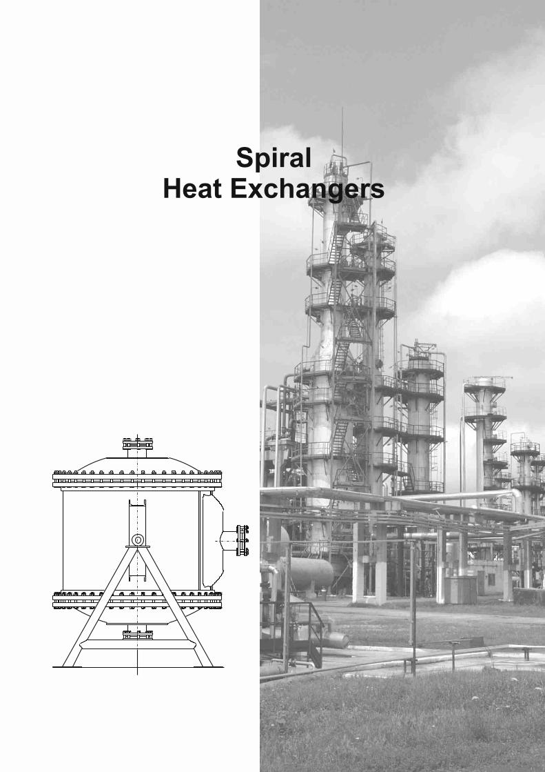
Spiral Heat Exchangers

Technical Catalogue
Spiral heat exchangers are recuperative heat-exchange apparatus designed for heat transfer from hot medium to a cold one through heat-transfer surface made of coiled strip spirally wound forming two non-intercommunicating rectangular cross-section spiral. In order to provide spirals with sufficient buckling strength under linear external pressure, аs well as to fix the distance between the spirals, the carrier pins and spacers are installed.
Heat exchangers are applied for heat exchange between operating media: liquid-liquid, gas-gas and gas-liquid, аs well as vapor and vapor-gas mixture condensation. Heat exchangers can operate both under vacuum and under
2pressure of operating medium up to 10 kgf/сm , within the temperature range of operating medium from minus 20ºС tо +200ºС. Spiral heat exchangers can be made of any rolled material subjected to cold treatment and welding.
Spiral heat exchangers are heavy-duty apparatus, they show high and relatively stable heat transfer coefficient, structure compactability, increased coolant rate, uniformity of coolant flow area in the canal operating space; due to this fact the heat-transfer surface contamination is less than in apparatus of another type that enables to operate heat exchanger for prolonged period without cleaning.
Operating medium contra-flow motion is performed in the spiral heat exchanger. Cold medium enters the apparatus at the periphery and s located in the external channel; due to this heat exchanger has low radiation losses. Hydraulic resistance of spiral heat exchangers is lower than of tube-and-shell heat exchangers given the same liquid flow rate.
By the method of channel sealing the heat exchangers can be manufactured:
type 1 – with dead channels
type 2 – with end-to-end channel.
Spiral heat exchangers with dead channels are the most commonly used. Each of two channels of such heat exchanger is welded by one end from mutually opposite sides. Such sealing method prevents coolant mixing in case of gasket joint leakage. After heat exchanger covers removal both channels can be easily cleaned.
Heat exchangers with dead channels can be made in the following versions:
version 1 – with flat covers, applied for heat exchange between operating media: liquid-liquid, gas-gas and gas-liquid;
version 2 – with conical cover, applied for heat exchange between operating media that change their aggregative state in the apparatus – during vapor and vapor-gas mixture condensation.
Heat exchangers used for steam condensing (condensers) are installed in a vertical position only. Steam or steam-gas mixture goes through the conical cover of the heat exchanger and into most of the spiral curves of the open channel simultaneously, except for a few external curves. The vertical position of channels excludes the possibility of condensate plugs and fluid hammers. The produced condensate flows down along the vertical channel walls, is collected in the bottom part of the heat exchanger and flows through the spiral into the condensate drain nozzle located in the bottom part of the overflow chamber. The remaining non-condensed part of the medium goes through a few of the external channel curves via a spiral, becomes cooled and is drained away through a nozzle.
In type 2 heat exchangers (with end-to-end channels), one channel is produced to be open on both sides, which allows to carry out its cleaning while the covers are removed, and the second one, the so-called “blind” channel, is welded on both ends. The “blind” channel cannot be cleaned via mechanical means, so it is used for the supply of mediums that do not leave any residue.
Heat exchangers with an end-to-end channel can be manufactured in the following makes:
make 1 – used for pre-heating of waste water and other polluted mediums. They are coiled with channels of varying breadth: the steam or water supply channel is narrow and is called “blind”, and the channel for polluted medium is wide, end-to-end. The machines have two flat covers, one of which is screw-on and easy to remove, allowing to reduce the disassembly time of the heat exchanger for the end-to-end channel cleaning;
make 2 – used for pre-heating or cooling of high-viscosity liquids and gases. The machines are furnished with two spherical covers, allowing the high-viscosity medium to go into all the curves of the end channel at the same time.
6 Spiral Heat Exchangers

Heat Exchagers
Spiral heat exchanger of 1 type, design 1,2
Spiral heat exchanger of 2 type, design 1
Spiral heat exchanger of 2 type, design 2
Spiral Heat Exchangers7
H
h
h1
Design 2
Design 2
E
D
L1
L2
B
C
L
4 holes Ж25
D А320
1395
665
700
1330
4 holes Ж22
595
C
380
390
1053
B
4 holes Ж25
C
965
1150
1290
1080
750
620А
D E

Technical Catalogue
Types and basic parameters of spiral heat exchangers
Weight, kg
Р, MPa
Heat
exch
an
ge
2 s
urf
ace, m
Ch
an
nel w
idth
, m
m Н h h1 l A A1 A2 DN
Wid
th o
f str
ip,
mm
Len
gth
of
ch
an
nel,
m
Ch
an
nel
cro
ss-s
ecti
on
al
2are
a, m
Flo
w c
ap
acit
y a
t v
elo
cit
y 1
m/s
, 3
m/h
0.6 1.0
Str
ip m
ate
rial
(as t
o
GO
ST
5632-7
2)
10 1170 940 700 560 900 1060 250 65 400 12.5 0.0048 17.28 970 1170Steel
12Х18Н10Т
20 1230 1000 730 620 1380 400 25 0.0048 17.28 1720 1770Steel
12Х18Н10Т
31.5 1350 1100 800 770960
1485 500 31.5 0.006 21.6 2300 2560Steel
10Х17Н13М2Т
40 1850 1600 1050 700 1330 1300
320 100
20 2430 2760
50 720 1460 25 2990 3460
63 810 1640 31.5 3800 4260
80
1930 1660 1100
1800
1000 0.012 43.2
4700 5450
100
12
2180 1910 1225900
1400
1960
400 150
125040
0,015 54 6050 6680
Steel12Х18Н10Т
Basic dimensions (mm) and characteristics of heat exchangers of type 1, design 1 made of stainless steel
Table 1.1
Pressure, МPа2(kgf/cm )
Type Design Purpose Nominal
heat exchange surface,
2mExcess Residual
Working media
temperature, °С
1 – with plain cover
For heat-exchaning between media: liquid-liquid, gas-gas, liquid-gas1 - with
dead-endchannels
2 – with cone-shaped
cover
For steam condensation and steam-and-gas mix
heat exchanging
10; 20;31.5; 40;50; 63;80; 100
to 1.0 (10)
not lower 0.08 (0.8)
1 – with plain flap
cover
For sewage water and other polluted media heating
0.8 (8)
2 -withend-to-end channels 2 – with
spherical cover
20
0.6 (6)
-
From -20 to +20
Table 1.2
Types and basic parameters of spiral heat exchangers are listed in the Table 1.1.
For spiral heat exchangers manufacturing besides of steel, specified in steel grades catalog, another materials can be used as well.
Basic dimensions and characteristics of spiral heat exchangers are given in corresponding tables.
Spiral heat exchangers with dimensions which are not specified in the catalog, if necessary can be designed and manufactured in accordance with State Standard GOST 12067.
The example of designation:Heat exchanger S1-31.5-6-1КLegend:S – spiral;1 – type of heat exchanger;
231.5 – heat exchange surface, m ; 26 – nominal pressure, kgf/cm ;
1 – design;К – material (К – corrosion-resistant, U – carbon).
8
For high-viscosity liquids and gases
Spiral Heat Exchangers

Heat Exchagers
20 1150 250 14.3 1650 1680
31.5 630
1350 22.5 2600 2630
40
1610 1300 960
750
1230
1450320
100 700
28.6
0.0084 30.24
3200 3230
Ст3сп4
50 1500 22.7 3800 3960
63 2030 1760 1150 720 1525
15851100
28.60.0138 49.68
4740 4760
80 1930 1660 1100 1800 1000 0.012 43.2 5430 5450
100
12
2180 1910 1225
900 1400
1960
400 150
1250
40
0.015 54 5930 5960
Ст3сп5
Basic dimensions (mm) and characteristics of heat exchangers of type 1, design 1 made of carbon steel
Basic dimensions (mm) and characteristics of heat exchangers of type 1, design 2 made of corrosion-resistant steel
Table 1.3
Weight, kg
Р, МPа
Н h h1 l L L1 L2 AB,C,D
E
Fo
r I
wo
rkin
g m
ed
ium
0.6 1.0
10 1230 1000 700 560 900 1060 250 200 65 50 12.5 0.123 960 1160 Steel
12Х18Н10Т
20 1290 1060 730 620 1380
400 25 0.264
0.0048 17.28 1720 1750
Steel 12Х18Н10Т
31.5 1410 1160 800 770
960 1485 500 31.5 0.337 0.006 21.6 2200 2470
Steel 10Х17Н13М2Т
40 1910 1660 1050 700 1330 1300
320 250 100 65
20 0.208 2420 2700
50 720 1460 25 0.264 2920 3400
63 810 1640 31.5 0.337 3700 4200
80
1990 1720 1100
1800
1000 0.012 43.2
4550 5000
100
12
2250 2000 1270 900
1400
1960
400 300 150 80
1250 40 0.432
0.015 54 5700 5900
Steel 12Х18Н10Т
Table 1.4
9 Spiral Heat Exchangers
Weight, kg
Р, MPaHeat
exch
an
ge
2 s
urf
ace, m
Ch
an
nel w
idth
, m
m
Н h h1 l A A1 A2 DN
Wid
th o
f str
ip,
mm
Len
gth
of
ch
an
nel,
m
Ch
an
nel
cro
ss-s
ecti
on
al
2are
a, m
Flo
w c
ap
acit
y a
t v
elo
cit
y 1
m/s
, 3
m/h
0.6 1.0
Str
ip m
ate
rial
(as t
o
GO
ST
5632-7
2)
Heat
exch
an
ge
2 s
urf
ace, m
Ch
an
nel w
idth
, m
m
Wid
th o
f str
ip,
mm
Len
gth
of
ch
an
nel, m Channel
cross-sectional
2area, m
Flo
w c
ap
acit
y a
t 3 v
elo
cit
y 1
m/s
, m
/h
Str
ip m
ate
rial
(as t
o
GO
ST
5632-7
2)
Fo
r II
wo
rkin
g m
ed
ium

Technical Catalogue
22.5
40
20 1150 250
31.5630
1350
40
16101360 900
750
1230
1450320
50 1500
6320901820 1150 720 1525
1585
80 19901720 1100 1800
100
12
22502000 1270900 1400
1960
400
250 100 65 700
1100
1000300 150 80
1250
14.3 0.123 1580 1650
0.236 2500 2600
28.6 0.34
0.0084 30.24
3050 3200
Cт3сп4
22.7 0.275 3750 3940
28.6 0.3360.0138 49.68
4720 4740
31.5 0.012 43.2 5420 5430
400.43
0.015 54 5910 59
Ст3сп5
20 25 12 100 500 20 0.0125 0.006 45 21.6 2400Steel
10Х17Н13М2Т
20 8 150 70 500 20 0.16 0.006 45 21.6 1200Steel
10Х17Н13М2Т
Basic dimensions (mm) and characteristics of heat exchangers of type 2, design 1Table 1.6
10
Basic dimensions (mm) and characteristics of heat exchangers of type 2, design 2Table 1.7
Basic dimensions (mm) and characteristics of heat exchangers of type 1, design 2 made of carbon steel
Table 1.5
Spiral Heat Exchangers
1 1 L
Weight, kg
Р, МPа
Н h h l L L 2 AB,C,D
E
Fo
r I
wo
rkin
g m
ed
ium
0.6 1.0
Heat
exch
an
ge
2 s
urf
ace, m
Ch
an
nel w
idth
, m
m
Wid
th o
f str
ip,
mm
Len
gth
of
ch
an
nel, m Channel
cross-sectional
2area, m
Flo
w c
ap
acit
y a
t 3 v
elo
cit
y 1
m/s
, m
/h
Str
ip m
ate
rial
(as t
o
GO
ST
5632-7
2)
Fo
r II
wo
rkin
g m
ed
ium
Wid
e
Narr
ow
A, B,C, D
Wid
e
Narr
ow
Wid
e
Narr
ow
Weight,kg
Channel cross-
sectional 2area, m
Flow capacity at velocity
31 m/s, m /h
Heat
exch
an
ge
2 s
urf
ace, m
Channel width, mm
Wid
th o
f str
ip, m
m
Len
gth
of
ch
an
nel, m
Str
ip m
ate
rial
(as t
o
GO
ST
5632-7
2)
A, B C,D
En
d-t
o-e
nd
Sp
iral
at
velo
cit
y0.0
1 m
/s
Weight,kg
Channel cross-
sectional 2area, m
Flow capacity, 3m /h
Heat
exch
an
ge
2 s
urf
ace, m
Ch
an
nel w
idth
, m
m
Wid
th o
f str
ip, m
m
Len
gth
of
ch
an
nel, m
Str
ip m
ate
rial
(as t
o
GO
ST
5632-7
2)
at
velo
cit
y1 m
/s
Heat Exchagers
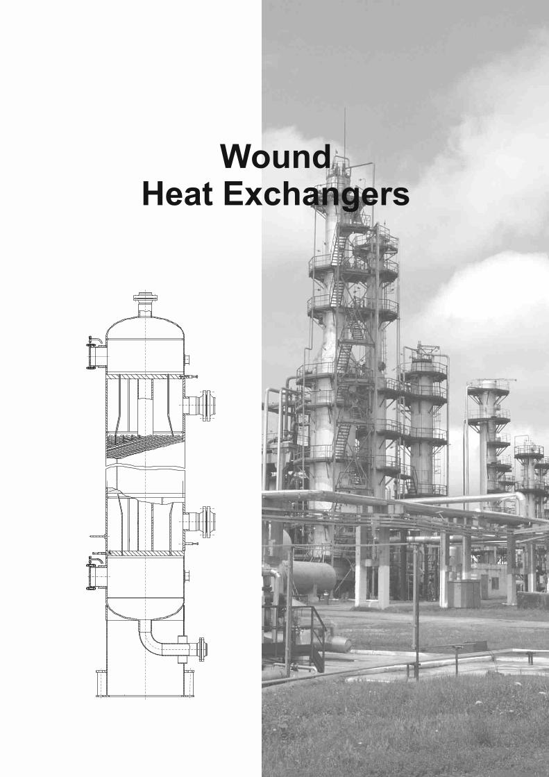
Wound Heat Exchangers

Technical Catalogue
Heat exchangers with wound tubes are vertical all-welded steel shell and tube heat-exchanging units with wound tubes and hard core. They are designed for heat-exchanging between the liquid, gas or vapour-liquid media that do not require mechanical cleaning of tube and shell sides surface. These units are applied in chemical, petrochemical, gas and other related industries.
General view and components of units are shown on Figure 2.1.
Heat exchangers with wound tubes can be manufactured of the following design:
- single-flow and multi-flow as to the tube side;
- single-section and multi-section (packaged) as to arrangement.
Production capabilities of JSC “SMNPO - Engineering” makes it possible to fulfill complete cycle of heat exchangers manufacturing, including tests and all kinds of basic material and welding joints non-destructive testing.
Basic parameters of heat exchangers can vary in wide range and are listed in Table 2.1.
Parameter Measuring unit Parameter value
Nominal pressure at tube and shell side
Working media temperature at tube and shell side
Nominal area of heat exchange surface
Internal diameter of unit (D)
Coil length (Н1)
Length of wound part (H2)
Unit weight
МPа
°С
Sq.m
mm
mm
mm
Tn
From 1.6 to 16
From -196 to +425
from 40 to 10000
Up to 3000
Up to 10000
Up to 8000
Up to 100
More detailed information on the geometry of heat exchangers with wound tubes with heat exchange surface area from 40 to 1250 sq.m is specified in Industrial Standard OST 26-01-1130.
Heat exchangers with dimensions which are not specified in Industrial Standard ОSТ 26-01-1130, if necessary can be designed by the specialists of JSC “SMNPO - Engineering”
Heat exchanger material is defined on material of heat-exchange tubes as the most metal-intensive part of the unit, and depending on medium temperature and corrosive power in accordance with Table 2.2.
Wound Heat Exchangers12
Table 2.1
Material Medium Temperature, °С
Grade GOSTUnit material design
From -40 to +425 Steel 10 1050-74
From -60 to +41 10Г2 4543-71
Carbon
Non-aggressive
From -196 to -61
Aggressive* From -196 to +425
12Х18Н10Т 5632-72Corrosion-proof
Table 2.2

Heat Exchagers
* Working media should not cause stress-corrosion cracking, pitch and pit corrosion of structural materials; corrosion rate should not exceed 0.05 mm per year.
For wound heat exchangers manufacturing besides of steel, specified in steel grades catalog, another materials can be used as well.
Heat exchangers with wound tubes are units of intensive action, which are characterized by high and relatively stable heat exchange coefficient, a compact design, increased rate of coolant, section coolant flow path consistency within working area.
As a rule working media running is carried out against the flow in the heat exchanger.
1 - tube sheet;2 - core;3 - bottom:4 - central shell (two-piece) ;5 - end shell (two-piece); 6 - rider ring;7 - flange;8 - shell side nozzle;9 - tube side nozzle;10 - blow connection (nozzle);11 - degas nozzle at hydraulic test;12 - water drain nozzle after hydraulic test;13 - heat-exchanging tube;14 - rod for unit plumbing;15 - support;16 - trunnion
13
7
1
2
5
4
14
12
15
H2
H1
H
3
6
11
13
8
10
16
9
D
Fig. 2.1
Wound Heat Exchangers

Technical Catalogue
Heat Exchangers Shell and Tube Heat Exchangers with Floating Head,
Shell and Tube Heat Exchangers with “U”-Shaped Tubesand Tube Bundles to them
as to Specification TU 3612-023-00220302-01

Heat Exchagers
These heat exchangers are designed for heat exchanging of liquid and gaseous media in processing of oil refining, petrochemical, chemical, oil, gas and other branches of industry. They are manufactured for national and international supply.
Water or other non-toxic, non-explosive and non-fire hazard liquid with 60°С boiling temperature at pressure 0.07 MPa serves as cooling agency in coolers and condensing apparatus.
These heat exchangers can be operated in temperate and tropical climatic conditions. Climatic design “U” and “T”, item category 1according to GOST 15150.
The heat exchangers are designed for installation in geographic areas with seismicity up to 7 points on the highest 12-point scale.
Technical requirements to materials, manufacture, acceptance, testing methods and preservation of apparatuses per SOU МPP 71.120-217:2009, GOST R 52630 and Technical Regulation of Customs Union 032/2013.
The example of heat exchanger designation when ordering :
Horizontal floating-head heat exchanger (TPG), with shell diameter 1000 mm, nominal pressure in tubes and shell 2.5 МPа, material version M1, with plain heat-transferring tubes (G) of 20 mm diameter and 6 m length, located at corners of equilateral triangles (T), 4-passes through tube side, climatic version (U), with components for heat-insultor fixing.
Heat exchanger
1000 TPG-2.5-М1/20ГG6-Т-4-U-I
Specifications TU 3612-023-00220302-01
Vertical floating-head heat exchanger (TPV), with shell diameter 325 mm, nominal pressure in tubes and shell 2.5 МPа, material version M1, with plain heat-transferring tubes (G) of 25 mm diameter and 3 m length, located at apexes of squares (K), 2-passes through tube side, climatic version (T), without components for heat-insultor fixing.
Heat exchanger
325 ТPV-2.5-М1/25G-3-К-2-Т
Specifications TU 3612-023-00220302-01
Horizontal floating-head cooler (KhPG), with shell diameter 800 mm, nominal pressure in tubes 1.0 MPa and in shell 4.0 МPа, material version M3, with plain heat-transferring tubes (G) of 20 mm diameter and 6 m length, located at corners of equilateral triangles (T), 4-passes through tube side, climatic version (U), with components for heat-insultor fixing.
Cooler
800 KhPG-1.0-4.0-МЗ/20G-6-Т-4-U-I
Specifications TU 3612-023-00220302-01
Vertical floating-head cooler (KhPV), with shell diameter 325 mm, nominal pressure in tubes 0.6 MPa and in shell 4.0 МPа, material version M1, with plain heat-transferring tubes (G) of 25 mm diameter and 3 m length, located at apexes of squares (K), 2-passes through tube side, climatic version (T), without components for heat-insultor fixing.
Cooler
325 KhPV-0.6-4.0-М1/25G-3-К-2-Т
Specifications TU 3612-023-00220302-01
Floating-head condensing apparatus (KP), with shell diameter 600 mm, nominal pressure in tubes 1.0 MPa and in shell 2.5 МPа, material version M12, with plain heat-transferring tubes (G) of 25 mm diameter and 6 m length, located at corners of equilateral triangles (T), 6-passes through tube side, climatic version (U), with components for heat-insultor fixing.
Condensing apparatus
600 КP-1,0-2,5-М 12/25Г-6-Т-6-У-И
Specifications TU36 12-023-00220302-01
For heat exchangers with U-shaped tubes
Heat exchanger with U-shaped tubes (TU), with shell diameter 1400 mm, nominal pressure in tubes and shell 1.6 МPа, material version M1, with plain heat-transferring tubes (G) of 25 mm diameter and 6 m length, located at corners of equilateral triangles (T), 2-passes through tube side, climatic version (U), with components for heat-insultor fixing.
Heat exchanger
1400 ТU-1.6-М1/25G-6-Т-2-U-I
Specifications TU 3612-023-00220302-00
Shell and Tube Heat Exchangers with Floating Head,Shell and Tube Heat Exchangers with “U”-Shaped Tubes15

Technical Catalogue
The example of tube bundle designation when ordering (in the case of individual supply):
Tube bundle for horizontal floating-head heat exchanger (TPG), with shell diameter 1000 mm, nominal pressure in tubes and shell 2.5 МPа, material version M1, with plain heat-transferring tubes (G) of 25 mm diameter and 6 m length, located at apexes of squares (K), 4-passes through tube side, climatic version (T).
Tube bundle
1000 TPG-2.5-М1/20ГG6-K-4-T
Specifications TU 3612-023-00220302-00
Tube bundle for vertical floating-head cooler (KhPV), with shell diameter 500 mm, nominal pressure in tubes 1.0 MPa and in shell 2.5 МPа, material version M3, with plain heat-transferring tubes (G) of 25 mm diameter and 3 m length, located at apexes of squares (K), 2-passes through tube side, climatic version (U).
Tube bundle
500KhPV-1.0-2.5-МЗ/25G-3-К-2-U
Specifications TU 3612-023-00220302-00
Tube bundle for floating-head condensing apparatus (KP), with shell diameter 1200 mm, nominal pressure in tubes 1.0 MPa and in shell 2.5 МPа, material version M1, with plain heat-transferring tubes (G) of 25 mm diameter and 6 m length, located at corners of equilateral triangles (T), 2-passes through tube side, climatic version (U).
Tube bundle
1200 КP-1.0-2.5-М1/25G-6-Т-2-U
Specifications TU 3612-023-00220302-00
Tube bundles for heat exchanger with “U”-shaped tubes, with shell diameter 1400 mm, nominal pressure in tubes and in shell 2.5 МPа, material version M1, with plain heat-transferring tubes (G) of 25 mm diameter and 6 m length, located at corners of equilateral triangles (T), 2-passes through tube side, climatic version (U).
Tube bundle
1400 ТU-2.5-М1/25G-6-Т-2-U
Specifications TU 3612-023-00220302-00
When choosing units, thermotechnical calculations are carried out, as well as materials, providing resistance against media corrosion effects, are selected. The heat exchangers choice is carried out by the contractor of current specifications according to the order form which is in the annex.
It is allowed to choose the heat exchangers of that design contractor which applies this type of equipment. Thereby this contractor is responsible for correct choice of the heat exchangers.
When ordering heat exchangers and tube bundles (at their individual supply), it is necessary to submit order form contained in the annex.
Shell and Tube Heat Exchangers with Floating Head,Shell and Tube Heat Exchangers with “U”-Shaped Tubes16

Heat Exchagers
Ou
ter
Inn
er
In t
ub
es
In c
asi
ng
32
5
40
0
50
06
00
an
d 7
00
8
00
90
0 a
nd
10
00
1
20
03
25
40
05
00
60
0 a
nd
70
0
80
09
00
an
d 1
00
01
20
01
40
0
32
5;4
00
;50
0
60
0 a
nd
70
08
00
; 9
00
; 1
00
0;
12
00
14
00
32
5;
40
0;
50
0
60
0;
70
0;
80
0;9
00
; 1
00
0;1
20
0
14
00
KP
84
-61
0
-
60
0*;
70
0*;
80
0;
90
0;
10
00
, 1
20
0
Fro
m -
20
to
+4
00
Fro
m -
20
to
+6
0
- - -1
.0;
1.6
; 2
.51
.0;
1.6
; 2
.51
.0;
1.6
; 2
.51
.0;
1.6
; 2
.5- - - -
Up
to
1.0
Up
to
1.0
Up
to
1.0
- -
60
00
60
00
-
20
x2;
25
x2;
25
x2.5
-
2;
4;
6
-
TU
12
-13
70
32
5
40
0*;
50
0*;
60
0*;
70
0*;
80
0;
90
0;
10
00
; 1
20
0;
14
00
Fro
m -
30
to
+4
50
2.5
;4.0
2.5
; 4
.0;
6.3
2.5
; 4
.0;
6.3
1.6
; 2
.5;
4.0
; 6
.31
.6;
2.5
; 4
.0;
6.3
1.6
; 2
.5;
4.0
1,6
; 2
,52
.5;
4.0
2.5
; 4
.0;
6.3
2.5
; 4
.0;
6.3
1.6
; 2
.5;
4.0
; 6
.31
.6;
2.5
; 4
,0;
6.3
1.6
; 2
.5;
4.0
1.6
; 2
.51
.6;
2.5
30
00
; 6
00
0
60
00
60
00
; 9
00
0
60
00
; 9
00
0
2 2 2
Pa
ram
ete
r
2H
ea
t e
xch
an
ge
su
rfa
ce,
m
Sh
ell
dia
me
ter
Tem
pe
ratu
re o
f h
ea
t tr
an
sfe
rrin
g m
ed
ia,
°C
No
min
al p
ress
ure
, M
Pa
, in
sh
ell
for
he
at
exc
ha
ng
ers
of
dia
me
ter,
mm
No
min
al p
ress
ure
, M
Pa
, in
tu
be
s fo
r h
ea
t e
xch
an
ge
rs o
f d
iam
ete
r, m
m
Le
ng
th o
f h
ea
t e
xch
an
gin
g t
ub
es
stra
igh
tru
n,
mm
, fo
r h
ea
t e
xch
an
ge
rs o
f d
iam
ete
r, m
m
Ou
ter
dia
me
ter
an
d w
all
thic
kne
ss o
f h
ea
t e
xch
an
gin
g t
ub
es
(dia
me
ter
an
d t
hic
kne
ss)
Nu
mb
er
of
pa
sse
s th
rou
gh
tu
be
s fo
r h
ea
t e
xch
an
ge
rs o
f d
iam
ete
r, m
m
He
at
exc
ha
ng
ing
tu
be
s la
you
t in
tu
be
sh
ee
ts a
nd
pa
rtiti
on
wa
lls
10
-91
5
32
5
40
0*;
50
0*;
60
0*,
70
0*;
80
0;
90
0,
10
00
; 1
20
0
Fro
m -
30
to
+4
50
30
00
; 6
00
0
60
00
60
00
; 9
00
0
- 2
2;
4 -
At apexes o
f square
s a
nd
corn
ers
of equila
tera
l tr
iangle
s
TP
2.5
; 4
.0
2.5
; 4
.0;
6.3
2.5
; 4
.0;
6.3
; 8
.01
.6;
2.5
; 4
.0;
6.3
; 8
.01
.6;
2.5
; 4
.0;
6.3
; 8
.01
.6;
2.5
; 4
.0;
6.3
1.6
; 2
.5;
4.0
; 6
.32
.5;
4.0
2.5
; 4
.0;
6.3
2.5
; 4
.0;
6.3
; 8
.01
.6;
2.5
; 4
.0;
6.3
; 8
.01
.6;
2.5
; 4
.0;
6.3
; 8
.01
.6;
2.5
; 4
.0;
6.3
1.6
; 2
.5;
4.0
; 6
.3-
Kh
P
4.0
; 6
.3
4.0
; 6
.3
4.0
; 6
.32
.5;
4.0
; 6
.31
.6;
2.5
; 4
.0;
6.3
1.6
, 2
.5,4
.0,
6.3
1.6
; 2
.5;
4.0
; 6
.3
Up
to
1.0
-
At
corn
ers
of
eq
uila
tera
l tria
ng
les
17Shell and Tube Heat Exchangers with Floating Head,Shell and Tube Heat Exchangers with “U”-Shaped Tubes
Basic
para
mete
rs o
f h
eat
exch
an
gers
of
TP, K
hP, K
P, T
U t
yp
es
*It is
allo
wed to m
ake
heat exc
hangers
shell
of
tubes
with
oute
r dia
mete
r 4
26,
530,
630,
720 m
m
Pa
ram
ete
r v
alu
e f
or
he
at
ex
ch
an
ge
rs o
f th
e t
yp
e

Technical Catalogue
L*
A ±
6l1
*A
1 ±
6
DN
89
10
1112
12
3
4
56
7l3
DВ
H ± 6
DН
h±3
H/2 ± 3
13
14
15
l0 ±
kl2
± 3
DN
DN
1
l -
k
H ± 6
H/2 ± 3
4
Heat
exch
an
ger
of
Kh
PG
typ
e
1 - d
istr
ibutin
g c
ham
ber co
ver;
2 - g
ask
et o
f dis
trib
utin
g c
ham
ber;
3 - d
istr
ibutin
g c
ham
ber;
4 - s
hell
gask
et;
5 - s
hell;
6 - h
eat e
xchangin
g tu
be;
7 -
part
ition w
all;
8 - s
em
i-rings;
9 - m
ova
ble
tube s
heet; 1
0 - fl
oatin
g h
ead g
ask
et; 1
1 - fl
oatin
g h
ead c
ove
r; 1
2 - s
hell
cove
r; 1
3 - m
ova
ble
support
; 1
4 -
fixed s
upp
ort
; 1
5 -
fixed tu
be s
heet
18Shell and Tube Heat Exchangers with Floating Head,Shell and Tube Heat Exchangers with “U”-Shaped Tubes

Heat Exchagers
L*
A ±
6l1
*A
1 ±
6
DN
89
10
1112
12
3
4
56
7l3
DВ
H ± 6
DН
h±3
H/2 ± 3
14
15
l0 ±
kl2
± 3
DN
DN
1
H ± 6
H/2 ± 3
4
13
l -
k
Ап
пар
ат
тип
а Т
ПГ
1 -
dis
trib
utin
g c
ham
ber
cove
r;
2 -
gask
et of dis
trib
utin
g c
ham
ber;
3 -
dis
trib
utin
g c
ham
ber;
4 -
shell
gask
et;
5 -
shell;
6 -
heat
exc
hangin
g t
ube;
7 - p
art
ition w
all;
8 - s
em
i-rings;
9 - m
ova
ble
tube s
heet;
10 - fl
oatin
g h
ead g
ask
et;
11
- fl
oatin
g h
ead c
ove
r; 12 - s
hell
cove
r; 13 - m
ova
ble
support
;
14 - fi
xed s
upport
; 1
5 - fi
xed tu
be s
heet.
Shell and Tube Heat Exchangers with Floating Head,Shell and Tube Heat Exchangers with “U”-Shaped Tubes19

Technical Catalogue
Shell and Tube Heat Exchangers with Floating Head,Shell and Tube Heat Exchangers with “U”-Shaped Tubes20
Basic
dim
en
sio
ns o
f T
P a
nd
Kh
P t
yp
es h
eat
exch
an
gers
Dim
ensi
ons,
mm
Part
itio
n w
alls
layo
ut
DN
at
pas
ses
nu
mb
er t
ho
ug
h t
ub
esS
hell ID
Di
Pre
ssu
re
РN
, M
Pa,
max
L*
Tu
bes
len
gth
ll
Н
24
DN
10
l3N
um
ber
АА
1
2.5
325**
4.0
2.5
4.0
400
6.3
2.5
4.0
6.3
500
8.0
1.6
2.5
4.0
6.3
600
8.0
1.6
2.5
4.0
6.3
700
8.0
3690
6690
3730
6730
3720
6720
3750
6750
3800
6800
3835
6835
3960
6960
4020
7020
4150
7150
6900
6950
7150
7300
7380
6950
7100
7280
7460
7580
3000
6000
1500
3000
3000
6000
1500
3000
3000
6000
1500
3000
3000
6000
1500
3000
3000
6000
1500
3000
3000
6000
1500
3000
3000
6000
1500
3000
3000
6000
1500
3000
3000
6000
1500
3000
6000
3000
6000
3000
16
38
140
16
38
10
24
10
24
210
10
24 8 20 8 20 8 18
260
6 18
16
320
14
14
360
12
600
714
810
954
1130
1060
1106
1300
1156
1198
1262
1324
1396
100
-100
150
-150
200
150
200
200
150
200
450
490
500
550
550
650
800
600
640
770
1000
600
640
720
850
1050
2350
5350
2330
5330
2250
5250
5250
2150
5150
2200
5200
2200
5200
2060
5060
1700
4700
5100
5060
4760
4560
5100
5000
4750
4450
2250

Heat Exchagers
1.6
74
65
10
46
56
00
09
00
03
00
06
00
01
22
05
10
08
10
0
2.5
75
50
10
55
06
00
09
00
03
00
06
00
01
22
0
70
05
10
08
10
0
4.0
76
00
10
60
06
00
09
00
03
00
06
00
0
39
0
12
20
13
54
75
04
90
07
90
0
6.3
78
00
10
80
06
00
09
00
03
00
06
00
03
85
12
20
14
30
89
04
67
07
67
0
80
0
8.0
81
00
111
00
60
00
90
00
30
00
60
00
39
01
01
81
68
4
25
02
00
25
0
12
50
42
00
72
00
1.6
75
60
10
56
06
00
09
00
03
00
06
00
01
01
81
37
47
20
50
00
80
00
2.5
76
80
10
68
06
00
09
00
03
00
06
00
01
01
81
39
87
50
49
50
79
50
4.0
78
40
10
84
06
00
09
00
03
00
06
00
01
01
61
49
28
40
47
50
77
50
90
0
6.3
81
00
111
00
60
00
90
00
30
00
60
00
44
5
10
16
15
42
25
02
00
25
0
110
04
40
07
40
0
1.6
76
15
10
61
56
00
09
00
03
00
06
00
01
01
65
00
08
00
0
2.5
77
20
10
72
06
00
09
00
03
00
06
00
0
50
01
01
6
75
05
00
08
00
0
4.0
78
70
10
87
06
00
09
00
03
00
06
00
04
90
10
16
84
04
80
07
80
0
10
00
6.3
82
50
112
50
60
00
90
00
30
00
60
00
50
08 14
15
58
30
02
00
30
0
13
30
42
00
72
00
1.6
78
00
10
80
06
00
09
00
03
00
06
00
08 12
82
04
76
07
76
0
2.5
79
00
10
90
06
00
09
00
03
00
06
00
08 12
87
04
76
07
76
0
4.0
81
00
111
00
60
00
90
00
30
00
60
00
6 12
17
80
113
04
35
07
35
0
12
00
6.3
84
50
114
50
60
00
90
00
30
00
60
00
61
5
6 10
19
00
30
02
50
30
0
14
00
38
00
68
00
Contin
uatio
n s
heet
* R
eco
mm
ended d
imensi
ons.
T
hey
are
speci
fied a
t the d
eve
lopm
ent of deta
il desi
gn d
ocu
menta
tion.
** S
hell
oute
r dia
mete
r (O
D),
Do.
Note
: D
imensi
on 4
* fo
r heat exc
hangers
with
shell
dia
mete
r 325-7
00 m
m is
calc
ula
ted in
clusi
ve o
f applic
atio
n o
f dis
trib
utin
g c
ham
ber
pla
in c
ove
r
21Shell and Tube Heat Exchangers with Floating Head,Shell and Tube Heat Exchangers with “U”-Shaped Tubes
Dim
ensi
ons,
mm
Part
itio
n w
alls
layo
ut
DN
at
pas
ses
nu
mb
er t
ho
ug
h t
ub
esS
hell ID
Di
Pre
ssu
re
РN
, M
Pa,
max
L*
Tu
bes
len
gth
ll
Н
24
DN
10
l3N
um
ber
АА
1

Technical Catalogue
* shell outer diameter
A0
d0
h1 =
l0 +
l2
Note:
1. Two oppositely facing midfeathers are installed at floating head on the tube bundle.
2. Heat exchangers and coolers of TPV and KhPV types should be installed indoor with temperature which is not bellow 0°С.
3. d0 - diameter of support foundation bolt hole
4. l0 and l2 - in accordance with figures and tables
Shell inner diameter
325* 562
400 2 674 24
500 830
d0А0Supports number
Dimensions, mm
22Heat Exchangers of TPV and KhPV Types with Tube Length 3000 mm

Heat Exchagers
1 -
dis
trib
utin
g c
ham
ber
cove
r;
2 -
gask
et of dis
trib
utin
g c
ham
ber;
3 -
dis
trib
utin
g c
ham
ber;
4 -
sh
ell
gask
et;
5 -
shell;
6 -
heat exc
hangin
g tube
;
7 - p
art
ition w
all;
8 - s
em
i-rings;
9 - m
ova
ble
tube s
heet;
10 - fl
oatin
g h
ead g
ask
et;
11
- fl
oatin
g h
ead c
ove
r; 12 - s
hell
cove
r; 13 - m
ova
ble
support
;
14 -
fixed s
upport
; 1
5 -
fixed tu
be s
heet
l1*
L*
1100 ±
64500 ±
6
12
34
56
7
89
10
1112
900
DN
14
15
DN
1
13
DN
2
DВ
h±3
650 ±
33000 ±
k
900 x
5 =
4500 ±
k
6000 -
k
23 Heat Exchangers of KP Type
Heat
exch
an
ger
of
KP
typ
e
DN
H ± 6
H/2 ± 3
H ± 6
H/2 ± 3

Technical Catalogue
DN at passes number through tubes Shell ID
Di
Pressure PN, MPa,
max
L*
l1*
H
2 4 6
DN1
1.0
300
1.6 6800 290
250 600
2.5 6850 310
1060
200
100
1.0
350
1.6 6930 320 1156
250 700
2.5 7000 340 1198
200 150 100
200
100
1.0
400
1.6 7050 340
300 800
2.5 7130 370
1354
250
150
1.0
400
1.6 7140 360 1374
300 900
2.5 7250 400 1398
250 200 150
250
150
1.0
400
1.6 7290 410
1000
2.5 7390 430
1558 200 150 300
200
1.0
500
1.6 7550 430
400 1200
2.5 7720 470
1780
300
250 200
350
250
Basic dimensions of heat exchangers of KP type
* Recommended dimensions. They are specified at the development of detail design documentation.
24 Heat Exchangers of KP Type
DN2
Dimensions, mm

Heat Exchagers
1 -
dis
trib
utin
g c
ham
ber;
2 -
dis
trib
utin
g c
ham
ber
gask
et; 3 -
tube s
heet; 4 -
shell;
5 -
heat exc
han
gin
g t
ube;
6 -
part
ition w
all;
7 -
mova
ble
support
; 8
- fix
ed s
upport
; 9
- s
hell
gask
et
L*
12
34
56
DN
DN
78
9
DN
l ± k
- le
ng
th o
f tu
be
str
aig
ht
run
50
Heat Exchangers of TU Type
Heat
exch
an
ger
of
TU
typ
e
A ±
6l1
*A
1 ±
6
l3
DВ
H ± 6
DН
h±3
H/2 ± 3
l0 ±
kl2
± 3
H ± 6
H/2 ± 3
25

Technical Catalogue
Basic dimensions of heat exchangers of TU type
2.5 38006800
30006000
15003000
1636
45025005500
325**4.0
38006800
30006000
15003000
2301636
600 490
24605460
2.5 39406940
30006000
15003000
1226
25005500
4.0 41207120
30006000
15003000
2701226
714 50025005500
400
6.3
40107010
30006000
15003000
2801226
810
100
24605460
2.5
40707070
30006000
15003000
1022
25005500
4.0
40957095
30006000
15003000
3251022
550
25005500
500
6.3
41707170
30006000
15003000
3451022
954
150
65024605460
1.6
7200 3702.5
7240
600 5400
4.0
7260400
1060
640600
6.3
7370
6000 3000
440
16
1106
200
7705360
1.6
7260 1156 6002.5
7300 1198 640
5400
4.0
7320 1262 720700
6.3
7450
6000 3000 38014
1324
200
8505360
1.6
730010300
60009000
30006000
1220
54008400
2.5
731510315
60009000
30006000
1220
70054008400
4.0
736010360
60009000
30006000
1220
1354
75053608360
800
6.3
755010550
60009000
30006000
420
1220
1430 91053608360
1.6
745010450
60009000
30006000
1218
1374 72054008400
2.5
745010450
60009000
30006000
1218
1398 75054008400
900
4.0
754010540
60009000
30006000
445
1218
1492
250
84053608360
1.6
762510625
60009000
30006000
1016
54008400
2.5
762510625
60009000
30006000
1016
75054008400
1000
4.0
766010660
60009000
30006000
500
1016
1558 300
88053608360
1.6
772010720
60009000
30006000
814
82054008400
12002.5
780010800
60009000
30006000
615814
1780 300870
53608360
1.6
805511055
60009000
30006000
812
52008200
14002.5
807511075
60009000
30006000
670812
1980 350 100052008200
* Recommended dimensions. They are specified at the development of detail design documentation.** Shell outer diameter, Do.
26 Heat Exchangers of TU Type
Dimensions, mm
Partition walls layoutL*
Tubes length
ll0
Number
Н Nozzles DN
А А1
l3
Shell ID, Di
Pressure PN, MPa,
max

Heat Exchagers
2H
ea
t e
xc
ha
ng
e s
urf
ac
e,
m,
at
lay
ou
t o
f tu
be
s i
n s
he
et
Cle
ar
op
en
ing
are
a o
f o
ne
pa
ss
2 t
hro
ug
h t
ub
es
, m
, m
in,
at
lay
ou
t o
f tu
be
s i
n s
he
et
2C
lea
r o
pe
nin
g a
rea
as
to
sh
ell
sid
e,
m,
at
lay
ou
t o
f tu
be
s i
n s
he
et
At
sq
ua
re a
pe
xe
s
At
tria
ng
le c
orn
ers
On
sq
ua
re a
pe
xe
sO
n t
ria
ng
le c
orn
ers
At
sq
ua
re a
pe
xe
sA
t tr
ian
gle
co
rne
rs
At
tub
es
str
aig
ht
run
, m
m
At
tub
e w
all
th
ick
ne
ss
, m
m
Sh
ell
ID
, m
m
Tu
be
sO
D,
mm
Nu
mb
er
of
pa
ss
es
th
rou
gh
tu
be
s
30
00
60
00
90
00
60
00
90
00
2.0
2.5
2.0
2.5
In
pa
rtit
ion
wa
ll s
lot
Be
twe
en
p
art
itio
n
wa
lls*
20
13
.22
6.4
--
-0
.00
70
--
-0
.01
00
.02
4-
-3
25
*2
52
10
.42
0.7
--
-0
.00
76
0.0
06
9-
-0
.011
0.0
28
--
20
23
.44
6.7
--
-0
.01
25
--
0.0
20
0.0
41
--
40
02
52
19
.33
8.6
--
-0
.01
42
0.0
12
9-
0.0
20
0.0
43
--
20
38
.87
7.6
--
-0
.02
07
--
0.0
32
0.0
64
--
50
02
52
31
.16
2.2
--
-0
.02
28
0.0
20
7-
0.0
32
0.0
63
--
2-
115
.3-
13
0.4
-0
.03
01
-0
.03
40
0.0
40
0.0
95
0.0
44
0.0
64
20
4-
10
5.5
-11
6.8
-0
.01
31
-0
.01
43
0.0
40
0.0
95
0.0
44
0.0
64
2-
95
.1-
10
6.5
-0
.03
43
0.0
311
0.0
38
10
.03
45
0.0
45
0.0
90
0.0
42
0.0
64
60
02
54
-8
5.7
-9
2.3
-0
.01
49
0.0
13
50
.01
59
0.0
14
40
.04
50
.09
00
.04
20
.06
4
2-
16
6.2
-1
83
.1-
0.0
43
6-
0.0
49
0-
0.0
63
0.1
08
0.0
56
0.0
94
20
4-
15
5.6
-1
71
.8-
0.0
20
1-
0.0
211
-0
.06
30
.10
80
.05
60
.09
4
2-
12
9.0
-1
47
.40
.04
64
0.0
42
10
.05
26
0.0
47
70
.06
10
.11
50
.05
60
.09
07
00
25
4-
118
.7-
13
2.4
0.0
19
00
.01
73
0.0
20
10
.01
82
0.0
61
0.1
15
0.0
56
0.0
90
2-
21
3.7
32
0.5
25
1.7
37
7.6
0.0
56
7-
0,0
66
1-
0.0
77
0.1
36
0.0
73
0.0
94
20
4-
20
0.8
30
1.3
23
3.6
35
0.4
0.0
26
1-
0.0
28
1-
0.0
77
0.1
36
0.0
73
0.0
94
2-
17
6.2
26
4.2
20
0.2
30
0.3
0.0
64
00
.05
81
0.0
72
40
.06
56
0.0
73
0.1
35
0.0
59
0.0
98
80
0
25
4-
16
3.0
24
4.0
18
2.3
27
3.4
0.0
27
00
.02
45
0.0
27
70
.02
51
0.0
73
0.1
35
0.0
59
0.0
98
2-
28
4.1
42
6.2
32
4.1
48
6.1
0.0
75
2-
0.0
85
6-
0.0
97
0.1
20
0.0
88
0.1
29
20
4-
27
0.5
40
5.8
30
3.0
45
4.4
0.0
15
4-
0.0
38
0-
0.0
97
0.1
20
0.0
88
0.1
29
2-
22
4.2
33
6.3
25
8.6
38
7.9
0.0
81
70
.07
41
0.0
94
20
.08
54
0.0
73
0.1
69
0.0
93
0.1
29
90
02
54
-2
10
.13
15
.12
38
.83
58
.20
.03
39
0.0
30
80
.04
33
0.0
39
30
.07
30
.16
90
.09
30
.12
9
2-
35
1.2
52
6.8
40
5.4
60
8.2
0.0
93
0-
0.1
07
1-
0.1
23
0.2
00
0.1
111
.14
02
04
-3
35
.45
03
.03
83
.65
75
.40
.04
38
-0
.04
92
-0
.12
30
.20
00
.111
0.1
40
2-
28
5.0
42
7.4
32
5.0
48
7.5
0.1
02
50
.09
29
0.1
17
40
.10
65
0.1
19
0.2
16
0.1
12
0.1
50
10
00
25
4-
26
8.9
40
3.4
30
2.4
45
3.6
0.0
47
80
.04
33
0.0
50
50
.04
58
0.1
19
0.2
16
0.1
12
0.1
50
2-
52
3.4
78
5.1
60
9.7
91
4.5
0.1
38
9-
0.1
61
0-
0.1
61
0.3
09
0.1
54
0.1
97
20
4-
50
3.0
75
4.5
58
1.8
87
2.7
0.0
66
1-
0.0
76
8-
0.1
61
0.3
09
0.1
54
0.1
97
2-
42
9.6
64
4.3
49
9.3
74
8.9
0.1
56
80
.14
22
0.1
81
70
.16
49
0.1
61
0.3
110
.14
40
.18
51
20
0
25
4-
40
9.8
61
4.7
47
0.1
70
5.1
0.0
74
10
.06
72
0.0
84
30
.07
57
0.1
61
0.3
110
.14
40
.18
5
Heat
exch
an
ge s
urf
ace a
s t
o t
ub
es o
ute
r d
iam
ete
r an
d c
lear
op
en
ing
are
a
as t
o t
ub
e a
nd
sh
ell s
ide f
or
heat
exch
an
gers
of
TP
an
d K
hP
typ
es
* S
hell
oute
r dia
mete
r, m
m**
Cle
ar
op
enin
g is
speci
fied for
row
1.
27 Heat-Exchange Surface of TP and KhP Types Heat Exchangers
In
pa
rtit
ion
wa
ll s
lot
Be
twe
en
p
art
itio
n
wa
lls
**
- -
- - - - - -
Technical Catalogue
Heat
- exch
an
ge s
urf
ace a
s t
o t
ub
es o
ute
r d
iam
ete
r an
d c
lear
op
en
ing
are
a a
s t
o t
ub
e a
nd
sh
ell s
ide fo
r h
eat
exch
an
gers
of
KP
typ
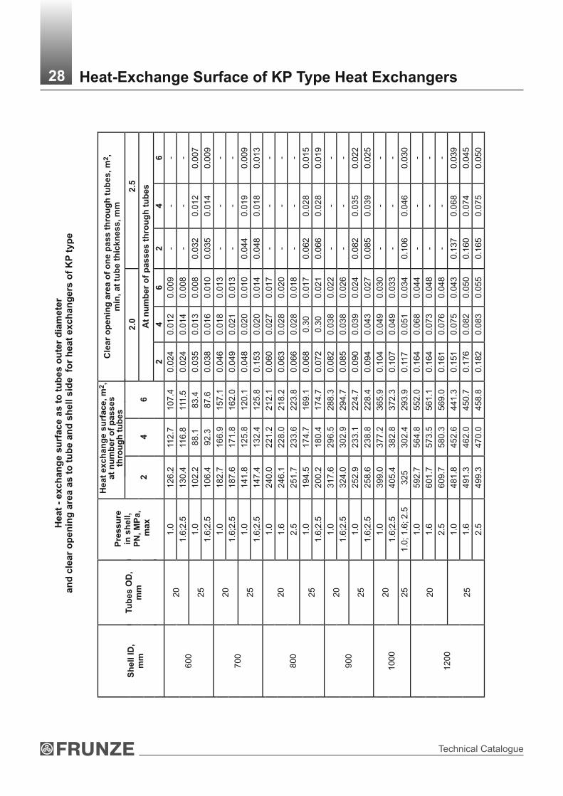
e
2H
ea
t e
xc
ha
ng
e s
urf
ac
e, m
, a
t n
um
be
r o
f p
as
se
s
thro
ug
h t
ub
es
2C
lea
r o
pe
nin
g a
rea o
f o
ne p
ass t
hro
ug
h t
ub
es, m
, m
in, at
tub
e t
hic
kn
ess, m
m
2.0
2.5
At
nu
mb
er
of
passes t
hro
ug
h t
ub
es
Sh
ell
ID
, m
m
Tu
bes O
D,
mm
Pre
ss
ure
in
sh
ell,
PN
, M
Pa
, m
ax
24
6
24
62
46
1.0
12
6.2
112
.71
07
.40
.02
40
.01
20.0
09
--
-20
1.6
;2.5
13
0.4
116
.811
1.5
0.0
24
0.0
14
0.0
08
--
-
1.0
10
2.2
88
.18
3.4
0.0
35
0.0
13
0.0
08
0.0
32
0.0
12
0.0
07
600
25
1.6
;2.5
10
6.4
92
.38
7.6
0.0
38
0.0
16
0.0
10
0.0
35
0.0
14
0.0
09
1.0
18
2.7
16
6.9
15
7.1
0.0
46
0.0
18
0.0
13
--
-20
1.6
;2.5
18
7.6
17
1.8
16
2.0
0.0
49
0.0
21
0.0
13
--
-
1.0
14
1.8
12
5.8
12
0.1
0.0
48
0.0
20
0.0
10
0.0
44
0.0
19
0.0
09
700
25
1.6
;2.5
14
7.4
13
2.4
12
5.8
0.1
53
0.0
20
0.0
14
0.0
48
0.0
18
0.0
13
1.0
24
0.0
22
1.2
21
2.1
0.0
60
0.0
27
0.0
17
--
-
1.6
24
6.1
22
8.0
21
8.2
0.0
63
0.0
28
0.0
20
--
-20
2.5
25
1.7
23
3.6
22
3.8
0.0
66
0.0
28
0.0
18
--
-
1.0
19
4.5
17
4.7
16
9.1
0.0
68
0.3
00.0
17
0.0
62
0.0
28
0.0
15
800
25
1.6
;2.5
20
0.2
18
0.4
17
4.7
0.0
72
0.3
00.0
21
0.0
66
0.0
28
0.0
19
1.0
31
7.6
29
6.5
28
8.3
0.0
82
0.0
38
0.0
22
--
-20
1.6
;2.5
32
4.0
30
2.9
29
4.7
0.0
85
0.0
38
0.0
26
--
-
1.0
25
2.9
23
3.1
22
4.7
0.0
90
0.0
39
0.0
24
0.0
82
0.0
35
0.0
22
900
25
1.6
;2.5
25
8.6
23
8.8
22
8.4
0.0
94
0.0
43
0.0
27
0.0
85
0.0
39
0.0
25
1.0
39
9.0
37
7.2
36
5.9
0.1
04
0.0
49
0.0
30
--
-20
1.6
;2.5
40
5.4
38
2.8
37
2.3
0.1
07
0.0
49
0.0
33
--
-1000
25
1.0
; 1
.6; 2
.53
25
30
2.4
29
3.9
0.1
17
0.0
51
0.0
34
0.1
06
0.0
46
0.0
30
1.0
59
2.7
56
4.8
55
2.0
0.1
64
0.0
68
0.0
44
--
-
1.6
60
1.7
57
3.5
56
1.1
0.1
64
0.0
73
0.0
48
--
-20
2.5
60
9.7
58
0.3
56
9.0
0.1
61
0.0
76
0.0
48
--
-
1.0
48
1.8
45
2.6
44
1.3
0.1
51
0.0
75
0.0
43
0.1
37
0.0
68
0.0
39
1.6
49
1.3
46
2.0
45
0.7
0.1
76
0.0
82
0.0
50
0.1
60
0.0
74
0.0
45
1200
25
2.5
49
9.3
47
0.0
45
8.8
0.1
82
0.0
83
0.0
55
0.1
65
0.0
75
0.0
50
28 Heat-Exchange Surface of KP Type Heat Exchangers

Heat Exchagers
Heat-exchange surface as to tubes outer diameter and clear opening area as to tube and shell side for heat exchangers of TU type
20 16.3 32.2 - 0.0084 - 0.0101 0.0151325*
25 12.1 23.9 - 0.0087 0.0079 0.0129 0.0150
20 31.4 61.6 - 0.0161 - 0.0178 0.0280400
25 23.0 45.2 - 0.0163 0.0148 0.0255 0.0250
20 52.0 101.3 - 0.0263 - 0.0265 0.0400500
25 41.7 81.2 - 0.0291 0.0264 0.0269 0.0438
20 - 144.4 - 0.0374 - 0.0414 0.0603600
25 - 115.5 - 0.0412 0.0374 0.0397 0.0586
20 - 202.0 - 0.0521 - 0.0531 0.0720700
25 - 160.0 - 0.0568 0.0515 0.0801 0.0810
20 - 274.5 406.4 0.0703 - 0.0693 0.0880800
25 - 212.5 314.7 0.0751 0.0681 0.0772 0.0900
20 - 353.7 522.9 0.0902 - 0.0849 0.1032900
25 - 286.9 423.9 0.01007 0.0914 0.0875 0.1183
20 - 450.0 664.0 0.1141 - 0.1049 0.13001000
25 - 354.2 522.8 0.1239 0.1124 0.1063 0.1375
20 - 662.4 974.4 0.1664 - 0.1496 0.20911200
25 - 554.5 800.7 0.1883 0.1708 0.1385 0.1999
20 - 934.1 1369.7 0.2323 - 0.1981 0.25461400
25 - 758.8 1112.5 0.2600 0.2358 0.1953 0.2513
* Shell outer diameter, mm** Clear opening is specified for row 1. Heat exchange surface is shown excluding tube sheets thickness.
29 Heat-Exchange Surface of TU Type Heat Exchangers
2Heat exchange surface, m , at length of tube straight
run, mm
Clear opening area of one pass
2through tubes, m , min, at tube wall thickness, mm
Clear opening area as to shell side,
2 m
Shell ID,mm
Tubes OD, mm
3000 6000 9000 2.0 2.5In
partition wall slot
Between partition walls**

Technical Catalogue
Mate
rials
fo
r T
P, K
hP,
KP, T
U t
yp
es h
eat
exch
an
gers
assem
bly
un
its a
nd
main
co
mp
on
en
ts m
an
ufa
ctu
rin
g
1)
Apply
fo
r K
hP, K
P typ
es
only
.2)
Apply
fo
r T
P, T
U typ
es.
3)
Apply
by the a
gre
em
ent w
ith C
ust
om
er
only
.4)
Apply
by
the a
gre
em
ent w
ith C
ust
om
er
at no
min
al p
ress
ure
up
to 4
.0 M
Pa a
nd tem
pera
ture
up to 4
000°С
.
Note
s:
Mat
eria
l
Heat exchangeer
type
Hea
t ex
chan
gee
rm
ater
ial
des
ign
S
hel
l an
d c
ove
rD
istr
ibu
tin
g
cham
ber
an
d c
ove
r
Hea
t ex
chan
gin
g t
ub
es
Tub
e sh
eet
Par
titi
on
wal
lS
hel
l g
aske
ts
Dis
trib
uti
ng
ch
amb
er
gas
kets
Flo
atin
g h
ead
gas
kets
TP,
TU
, K
hP, K
P
М1
Ste
el С
т3сп
as
to G
OS
T 3
80,
GO
ST
146
37tu
bes
- st
eel 2
0 as
to
GO
ST
105
0,
GO
ST
873
1, g
r. B
or
Ste
el С
т3сп
as
to G
OS
T 3
80,
GO
ST
107
06, g
r.B
1)S
teel
Ст3
сп,С
т3пс
a
s to
GO
ST
380
, G
OS
T 1
4637
stee
l 09Г
2С a
s to
GO
ST
552
0 tu
bes
- st
eel 2
0 as
to
GO
ST
105
0,
GO
ST
873
1, g
r. B
or
Ste
el С
т3сп
as
to G
OS
T 3
80,
GO
ST
107
06, g
r.B ,
Ste
el 1
0 an
d 20
as
to G
OS
T 1
050,
G
OS
T 5
50 g
r.A,
3)
GO
ST
873
3gr
.B a
nd e
lect
ric w
elde
d tu
bes
as to
dul
y a
ppro
ved
tech
nica
l4)
doc
umen
tatio
n
Ste
el 0
9Г2С
as
to G
OS
T 5
520
and
GO
ST
1928
1, G
OS
T 8
479
gr.
IV-К
П.2
45
Ст
3сп
as to
GO
ST
380
, G
OS
T 1
4637
Asb
esto
s-fr
ee g
aske
t mat
eria
ls o
f “F
renz
elit”
Com
pany
Alu
min
ium
of g
rade
А
Д a
s to
GO
ST
216
31.
Bra
ss Л
63
as to
GO
ST
220
8.
Ste
el 0
8 as
to
GO
ST
157
7, G
OS
T 9
045
ВГ.
G
r. Ш
KhP
, KP
М3
See
mat
eria
l des
ign
М1
Bra
ss Л
АМ
ш 7
7-2-
0.5
GO
ST
155
27,
GO
ST
216
46
Ste
el 0
9Г2С
as
to G
OS
T 5
520
and
GO
ST
1928
1, G
OS
T 8
479
gr.
IV-К
П.2
45 w
ithЛ
О 6
2-1
or Л
63 b
rass
sur
faci
ng a
s to
GO
ST
1552
7,G
OS
T 9
31
See
m
ater
ial
desi
gn М
1
Asb
esto
s-fr
ee g
aske
t mat
eria
ls o
f “F
renz
elit”
Com
pany
Bra
ss Л
63
As
to G
OS
T 2
208
KhP
, KP
М12
Ste
el 0
8Х22
Н6Г
as to
GO
ST
563
2,
GO
ST
994
1, s
teel
12Х
18Н
10Т
3 as
to
GO
ST
563
2,
GO
ST
994
1
Ste
el 0
9Г2С
as
to G
OS
T 5
520
and
GO
ST
1928
1, G
OS
T 8
479
See
mat
eria
l des
ign
М1
TP,
TU
, K
hP, K
P
М13
See
mat
eria
l des
ign
М1
Ste
el 1
2Х18
Н10
Т,18
Х18
Н10
Т
as to
GO
ST
563
2,
GO
ST
994
1
Ste
el 1
2Х18
Н10
Т, 0
8Х18
Н10
Т
as to
GO
ST
563
2, G
OS
T 7
350,
gr.
М2б
, GO
ST
250
54, g
r. IV
an
d du
ly a
ppro
ved
tech
nica
l doc
umen
tatio
n
See
mat
eria
l des
ign
М1
Ste
el 0
8Х18
Н10
As
to G
OS
T 7
350
Or
GO
ST
594
9
1.
It is
allo
wed to m
ake
ass
em
bly
units
of anoth
er
gra
des
mate
rials
, desc
ribed in
the
Indust
rial S
tandard
OS
T 2
6-2
91. T
hese
mate
rials
should
be o
f th
e s
am
e tech
nic
al
pro
pert
ies
and c
orr
osi
on r
esi
stance
as
those
whic
h a
re li
sted in
the table
.
2.
Mate
rials
lim
itatio
n a
nd s
pe
cific
atio
ns
should
com
ply
with
the Indust
rial S
tandard
O
ST
26-2
91.
3.
Gask
et m
ate
rial s
hould
be s
ele
cted c
onsi
dering w
ork
ing m
ediu
m, para
mete
rs a
nd
corr
osi
vity
.4.
It is
allo
wed to u
se s
piral-w
ound g
ask
ets
as
to O
ST
265.2
40.4
53.
30 Materials for Heat Exchangers Manufacturing

Heat Exchagers
Tu
be
s 2
0х
2,
len
gth
Tu
be
s 2
5х
2,
len
gth
Tu
bes
25х2.5
, le
ng
th
30
00
60
00
30
00
60
00
30
00
60
00
Sh
ell
in
ne
r d
iam
ete
r
Pre
ss
ure
P
N,
МP
а,
ma
xS
tee
l
Bra
ss
Ste
el
B
ras
sS
tee
l
Bra
ss
Ste
el
B
ras
s
Ste
el
S
tee
l
2.5
95
01
00
01
40
01
47
09
20
96
01
33
01
39
09
50
14
00
32
5*
4.0
115
011
80
16
00
16
70
10
70
115
01
53
01
56
011
50
16
00
2.5
13
90
14
20
20
50
21
50
13
40
13
70
19
40
20
50
14
00
20
70
4.0
16
90
17
40
23
40
24
30
16
40
16
80
22
40
23
00
17
00
23
60
40
0
6.3
21
90
-2
88
0-
21
40
-2
77
0-
22
00
29
00
2.5
20
80
21
40
30
30
31
40
19
70
20
00
28
00
28
80
20
70
30
00
4.0
25
10
26
00
36
80
37
90
24
10
24
50
34
50
35
30
25
00
36
50
6.3
33
10
-4
48
0-
32
00
-4
27
0-
33
00
44
50
50
0
8.0
42
70
-5
68
0-
41
60
-5
50
0-
56
50
2 p
as
se
s
1.6
39
40
41
00
--
37
00
38
40
--
39
90
-2
.54
18
04
30
0-
-3
88
04
01
0-
-4
20
0-
4.0
50
50
52
10
--
47
50
48
80
--
51
00
-6
.36
72
0-
--
65
00
--
-6
75
0-
8.0
81
00
--
-7
83
0-
--
81
50
-4
pa
ss
es
1
.63
82
03
96
0-
-3
60
03
72
0-
-3
92
0-
2.5
410
04
17
0-
-3
78
03
90
0-
-4
10
0-
4.0
48
80
50
20
--
47
00
48
20
--
50
00
-6
.36
48
0-
--
64
00
--
-6
62
0-
60
0
8.0
79
80
--
-7
73
0-
--
80
20
-2
pa
ss
es
1
.65
55
05
78
0-
-5
10
05
28
0-
-5
55
0-
2.5
41
00
64
10
--
57
30
59
10
--
61
80
-4
.04
88
07
56
0-
-6
88
07
06
0-
-7
33
0-
6.3
64
80
--
-9
30
0-
--
97
20
-8
.07
98
0-
--
118
70
--
-1
22
90
-4
pa
ss
es
1
.65
40
05
60
0-
-5
00
05
17
0-
-5
40
0-
2.5
60
50
62
50
--
56
50
58
20
--
60
50
-4
.07
16
07
36
0-
-6
75
06
92
0-
-7
15
0-
6.3
95
70
--
-9
18
0-
--
95
80
-
70
0
8.0
12
110
--
-11
72
0-
--
12
12
0-
2 p
as
se
s
1.6
70
00
74
00
93
50
93
40
67
90
70
40
87
50
90
80
71
00
95
50
2.5
75
00
79
00
10
10
01
06
50
71
50
74
50
93
00
96
80
76
00
10
27
04
.09
15
09
45
011
70
01
22
00
91
00
93
50
10
99
011
37
09
25
01
88
70
6.3
115
90
-1
45
80
-11
12
0-
13
87
0-
117
00
14
75
0
80
0
8.0
16
65
0-
20
20
0-
16
12
0-
19
49
0-
16
70
02
03
70
Tu
be
s 2
0х
2,
len
gth
Tu
be
s 2
5х
2,
len
gth
Tu
bes
25х2.5
, le
ng
th
60
00
90
00
60
00
90
00
60
00
90
00
Ste
el
B
ras
s
Ste
el
B
ras
sS
tee
l
Bra
ss
Ste
el
B
ras
sS
tee
l
Ste
el
Pre
ss
ure
P
N,
МP
а,
ma
x
Sh
ell
in
ne
r d
iam
ete
rW
eig
ht,
kg
We
igh
t, k
g31 Heat Exchangers of TP Type Weight
Hea
t exch
an
gers
of
TP
typ
e w
eig
ht
at
ho
les layo
ut
at
sq
ua
res a
pexes
Dim
ensi
ons,
mm
-

Technical Catalogue
Pre
ss
ure
P
N,
МP
а,
ma
x
Contin
uatio
n s
heet
* sh
ell
oute
r dia
mete
r
4 p
asses
1.6
6850
7150
9150
9570
6620
6860
8550
8800
6900
9300
2.5
7400
7850
9950
10370
7050
7350
9150
9400
7450
10100
4.0
9100
9360
11500
11920
8930
9170
10740
11090
9100
11650
6.3
11440
-14350
-109200
-13600
-11
500
14550
800
8.0
16500
-20000
-15950
-19240
-16500
20060
2 p
asses
1.6
8500
11500
8890
12090
7710
10290
8030
10760
8450
11420
2.5
9670
12950
10060
13540
8880
11740
9200
12210
9620
12870
4.0
11730
1511
012120
15
700
10880
13900
11200
14340
11610
15030
6.3
15800
-16190
-15030
-15350
-15750
19470
4 p
asses
1.6
8350
11260
8750
11820
7590
10070
7890
10520
8290
11140
2.5
9540
12720
9920
13820
8760
11520
9060
11970
9460
12590
4.0
11500
14860
11880
15420
10730
13660
11030
1411
011
420
14720
900
6.3
15620
-16000
-14850
-15160
-15550
19140
2 p
asses
1.6
10700
11200
14770
15500
9950
10550
13480
14250
10780
14900
2.5
11370
11850
15470
16200
10500
11100
14180
14900
11450
15600
4.0
13920
14400
18100
18900
13050
13650
16900
17650
14000
18200
6.3
18900
-24250
-18040
-23050
-18980
24400
4 p
asses
1.6
10480
10950
14420
15100
9700
10300
13150
13850
10500
14500
2.5
11150
11600
15120
15800
10300
10850
13860
14550
11300
15160
4.0
13690
14150
17750
18550
12850
13450
16600
17300
13750
17800
1000
6.3
18670
-23900
-17800
-22700
-18690
23960
2 p
asses
1.6
14720
15450
20040
211
40
13470
14080
18500
19400
14900
20370
2.5
16690
17600
21900
23000
15550
16200
20100
211
00
16900
22230
4.0
21200
21930
26680
27
800
19970
20800
25100
26000
21400
27000
6.3
28300
-35500
-27100
-33700
-28500
35830
4 p
asses
1.6
14560
15270
19600
20700
1311
80
13900
18100
18970
14640
19830
2.5
16280
17100
21500
22600
15290
15870
19900
20770
16500
21700
4.0
20900
21600
26300
27400
19680
20500
24800
25670
211
00
26700
1200
6.3
28000
-35060
-26800
-33300
-28220
35290
32 Weight of TP Type Heat ExchangersTu
bes 2
0х2, le
ng
thTu
bes 25х2, le
ng
thTu
bes 2
5х2.5
, le
ng
th
6000
9000
6000
9000
6000
9000
Ste
el
Bra
ss
Ste
el
Bra
ss
Ste
el
Bra
ss
Ste
el
Bra
ss
Ste
el
Ste
el
Weig
ht,
kg
Sh
ell
inn
er
dia
mete
r
Dim
ensi
ons,
mm
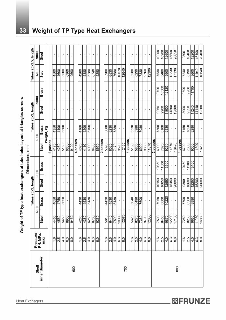
Heat Exchagers
Tu
bes 2
0х2, le
ng
thTu
bes 2
5х2, le
ng
thTu
bes 2
5х2.5
, le
ng
th
6000
9000
6000
9000
6000
9000
Ste
el
Bra
ss
Ste
el
Bra
ss
Ste
el
Bra
ss
Ste
el
Bra
ss
Ste
el
Ste
el
Weig
ht,
kg
2 p
asses
1.6
4450
4650
--
4170
4350
--
4500
-
2.5
4550
4750
--
4250
4400
--
4600
-
4.0
5450
5650
--
5150
5300
--
5500
-
6.3
6900
--
-6600
--
-6960
-
8.0
9450
--
-9100
--
-9500
-4 p
asses
1.6
4280
4430
--
4020
4160
--
4280
-
2.5
4380
4530
--
411
04200
--
4380
-
4.0
5280
5430
--
4990
510
0-
-5280
-
6.3
6700
--
-6430
--
-6740
-
600
8.0
9280
--
-8950
--
-9280
-2 p
asses
1.6
5810
4430
--
5390
5600
--
5900
-
2.5
6440
4530
--
6020
6230
--
6530
-
4.0
7590
5430
--
7170
7380
--
7680
-
6.3
10000
--
-9590
--
-10070
-
8.0
12570
--
-12160
--
-12640
-4 p
asses
1.6
5620
5840
--
5150
5330
--
5580
-
2.5
6270
6490
--
5800
5980
--
6230
-
4.0
7380
7600
--
6900
7080
--
7330
-
6.3
9790
--
-9330
--
-9760
-
700
8.0
12330
--
-11
870
--
-12300
-2 p
asses
1.6
7500
7950
10150
10850
6900
7300
9250
9700
7530
10200
2.5
8450
8800
10850
11500
7820
8100
9900
10300
8480
10900
4.0
9870
10220
12550
13500
9250
9530
11600
12120
9900
12600
6.3
12200
-15450
-11
570
-14500
-12230
15500
8.0
17100
-20800
-16470
-19860
-17130
20850
4 p
asses
1.6
7280
7700
9800
10450
6700
7150
8900
9300
7240
9800
2.5
8230
8560
10600
11100
7600
7850
9550
9900
8190
10460
4.0
9650
9980
12250
13100
9000
9280
11240
11700
9600
12200
6.3
11980
-15200
-11
300
-14140
-11
940
15100
800
8.0
16880
-20600
-16230
-19500
-16840
20400
Weig
ht
of
TP
typ
e h
eat
exch
an
gers
at
tub
e h
ole
s layo
ut
at
tria
ng
les c
orn
ers
33S
he
ll i
nn
er
dia
me
ter
Dim
ensi
ons,
mm
Weight of TP Type Heat ExchangersP
res
su
re
PN
, М
Pа
, m
ax

Technical Catalogue
1.6
9060
12340
9500
13010
8220
11060
8590
11600
9080
12360
2.5
10230
13790
10670
14460
9390
12510
9760
13050
10250
13810
4.0
12290
15950
12730
16620
11390
14670
11760
15180
12240
15970
6.3
16360
-16800
-15540
-15910
-16380
20410
1.6
8820
11970
9270
12600
8020
10710
8360
11220
8820
11930
2.5
10010
13430
10440
14060
9190
12160
9530
12670
9990
13380
4.0
11970
15570
12400
16200
11160
14300
11500
14810
11950
15510
900
6.3
16090
-16520
-15280
-15630
-16080
19930
1.6
11550
12100
15900
16750
10530
11150
14350
15150
11600
15950
2.5
12000
12650
16650
17490
11100
11750
15060
15850
12050
16680
4.0
14650
15200
19350
20200
13650
14300
17780
18600
14700
19400
6.3
19550
-24800
-18
530
-23950
-19600
24850
1.6
11230
11750
15420
16250
10190
10800
13850
14600
11200
15350
2.5
11750
12300
16170
16970
10760
11380
14560
15300
11750
16060
4.0
14350
14850
18870
19680
13300
13950
17300
18050
14350
18800
1000
6.3
19230
-24320
-1
8190
-23450
-19200
24200
1.6
16700
17550
23300
24600
15150
15900
211
60
22200
16800
23650
2.5
18600
19450
24900
26200
17040
17750
22750
23800
18700
25250
4.0
20600
21450
28500
29800
19350
20370
27150
28200
20800
28850
6.3
28950
-3605
0-
27490
-33900
-29150
36400
1.6
16350
17200
22690
23400
14800
15440
20530
21500
16290
22880
2.5
18200
19000
24300
25500
16620
17290
22100
23100
18190
24480
4.0
20190
21000
27890
29250
18930
19900
26500
27600
20300
28080
1200
6.3
28550
-3550
0-
27070
-33270
-28600
35600
Tu
bes, 20х2, le
ng
thTu
bes 2
5х2, le
ng
thTu
bes 2
5х2.5
, le
ng
th
6000
9000
6000
9000
6000
9000
Ste
el
Bra
ss
Ste
el
Bra
ss
Ste
el
Bra
ss
Ste
el
Bra
ss
Ste
el
Ste
el
Weig
ht,
kg
Sh
ell
in
ne
r d
iam
ete
r
Weight of TP Type Heat Exchangers
2 p
asses
4 p
asses
2 p
asses
4 p
asses
2 p
asses
4 p
asses
Dim
ensi
ons,
mm
Contin
uatio
n s
heet
34
Pre
ss
ure
P
N,
МP
а,
ma
x

Heat Exchagers
Tu
bes 2
0х2, le
ng
thTu
bes 2
5х2, le
ng
thTu
bes 25х2.5
, le
ng
th
3000
6000
3000
6000
3000
6000
Tu
bes m
ate
rial
Ste
el
Bra
ss
Ste
el
Bra
ss
Ste
el
Bra
ss
Ste
el
Bra
ss
Ste
el
Ste
el
4.0
1030
1070
1520
1570
1000
1050
1450
1490
1030
1520
325*
6.3
1360
-11
50
1530
1560
1150
1600
4.0
1640
1700
2250
2350
1590
1640
2150
2210
1650
2270
400
6.3
2000
-2750
-1950
-2600
-2010
2770
4.0
2400
2460
3430
3540
2300
2350
3300
3380
2390
3400
500
6.3
3000
-4180
-2890
-3980
-2990
4150
2 х
од
а
2.5
4150
4310
--
3880
4010
--
4200
-
4.0
4800
4960
--
4500
4630
--
4850
-
6.3
6260
--
-6000
--
-6290
-
4 х
од
а
2.5
4050
4190
--
3780
3900
--
4070
-
4.0
4680
4820
--
4400
4520
--
4720
-
600
6.3
6140
--
-5900
--
-6160
-
2 х
од
а
2.5
6030
6260
--
5580
5760
--
6030
-
4.0
6930
7160
--
6480
6660
--
6930
-
6.3
9030
--
-8590
--
-9010
-
4 х
од
а
2.5
5870
6070
--
5470
5640
--
5870
-
4.0
6700
6900
--
6290
6460
--
6690
-
700
6.3
8750
--
-8360
--
-8760
-
2 х
од
а
1.6
6690
7000
9200
9700
6220
6550
8490
8870
6800
9370
2.5
7180
7480
9780
10220
6700
69
50
9070
9450
7290
9950
4.0
8150
8450
10700
11200
7750
7920
9990
10500
8250
10870
6.3
10400
-13050
-9910
-12340
-10490
13220
4 х
од
а
1.6
6540
6850
8970
9390
6050
6400
8240
8590
6650
9060
2.5
7030
7350
9550
9970
6530
6770
8820
9170
7090
9640
4.0
8050
8400
10500
10950
7600
7840
9740
10100
8050
10560
800
6.3
10300
-12850
-9790
-12090
-10300
12910
Weig
ht
of
Kh
P t
yp
e h
eat
exch
an
gers
at
tub
e h
ole
s layo
ut
at
sq
uare
s a
pexes
35
Tu
bes 2
0х2, le
ng
thTu
bes 2
5х2, le
ng
thTu
bes 25х2.5
, le
ng
th
6000
9000
6000
9000
600
09
000
Tu
bes m
ate
rial
Ste
el
Bra
ss
Ste
el
Bra
ss
Ste
el
Bra
ss
Ste
el
Bra
ss
Ste
el
Ste
el
Weig
ht,
kg
Weig
ht,
kg
Sh
ell
in
ne
r d
iam
ete
r
Sh
ell
in
ne
r d
iam
ete
r
Dim
ensi
ons,
mm
Weight of KhP Type Heat ExchangersP
res
su
re
PN
, М
Pа
, m
ax
Pre
ss
ure
P
N,
МP
а,
ma
x

Technical Catalogue
Contin
uatio
n s
heet
Tu
be
s 2
0x
2,
len
gth
Tu
be
s 2
5x
2,
len
gth
Tu
be
s 2
5х
2.5
, le
ng
th
60
00
900
06
00
09
00
06
00
09
00
0
Tu
be
s m
ate
ria
l
Ste
el
Bra
ss
S
tee
l B
ras
sS
tee
l B
ras
sS
tee
l B
ras
sS
tee
l
Ste
el
We
igh
t, k
g2
pa
ss
es
1.6
84
00
114
00
87
90
119
90
76
10
10
19
07
93
01
06
60
83
50
113
20
2.5
97
20
13
00
01
011
01
35
90
89
30
117
90
92
50
12
26
09
67
01
29
20
4.0
115
10
14
89
011
90
01
54
80
10
66
01
36
80
10
98
01
41
20
113
90
14
81
0
6.3
15
09
0-
15
48
0-
14
32
0-
14
68
0-
15
04
18
76
04
pa
ss
es
1.6
82
40
111
50
86
40
117
10
74
80
99
60
77
80
10
41
08
18
011
03
0
2.5
95
40
12
72
09
92
01
32
80
87
60
115
20
90
60
119
70
94
60
12
59
0
4.0
111
90
14
55
011
57
01
511
01
04
20
13
35
01
07
20
13
80
011
110
14
41
0
90
0
6.3
14
76
0-
15
14
0-
13
99
0-
14
30
0-
14
69
01
82
80
2 p
as
se
s
1.6
10
22
01
07
50
13
92
01
46
50
94
00
99
00
12
63
01
33
00
10
30
01
40
50
2.5
110
20
115
00
14
77
01
55
00
10
16
01
06
00
13
48
01
42
00
111
00
14
90
0
4.0
13
22
01
37
00
16
92
01
76
80
12
36
01
27
60
15
63
01
63
50
13
30
01
70
50
6.3
18
90
0-
13
96
0-
18
04
0-
22
67
0-
18
98
02
40
90
4 p
as
se
s
1.6
10
05
01
06
00
13
55
01
43
50
92
50
97
50
12
40
01
31
00
10
15
01
37
50
2.5
10
80
011
30
01
44
50
15
20
01
00
00
10
45
01
32
50
13
96
01
09
50
14
65
0
4.0
12
99
01
34
50
16
57
01
72
70
12
12
01
25
00
15
27
01
58
50
13
15
01
66
00
10
00
6.3
18
67
0-
23
61
0-
17
80
0-
22
31
0-
18
70
02
36
50
2 p
as
se
s
1.6
15
00
01
57
50
20
27
02
14
00
13
87
01
50
00
18
50
01
94
00
15
20
02
06
00
2.5
16
75
01
75
00
22
10
02
32
00
15
47
01
61
00
20
20
02
110
01
69
00
22
40
0
4.0
21
40
02
22
00
26
95
02
81
00
20
17
02
08
00
25
10
02
60
00
21
60
02
72
40
6.3
28
30
0-
35
40
0-
27
10
0-
33
50
0-
28
50
03
57
30
4 p
as
se
s
1.6
14
75
01
54
60
19
83
02
09
00
13
58
01
41
60
18
10
01
89
70
14
84
02
00
60
2.5
16
55
01
72
50
21
70
02
28
00
15
29
01
58
70
19
90
01
07
70
16
54
02
18
60
4.0
21
20
02
20
00
26
70
02
78
00
19
88
02
04
60
24
80
02
56
70
21
24
02
67
00
12
00
6.3
28
00
0-
35
15
0-
26
80
0-
33
10
0-
28
22
03
52
00
*
shell
oute
r dia
mete
r
36S
he
ll
inn
er
dia
me
ter
Dim
ensi
ons,
mm
Weight of KhP Type Heat ExchangersP
res
su
re
PN
, М
Pа
, m
ax

Heat Exchagers
We
igh
t o
f K
hP
ty
pe
he
at
ex
ch
an
ge
rs a
t tu
be
ho
les
la
yo
ut
at
eq
uil
ate
ral
tria
ng
les
co
rne
rs
Tu
bes 2
0x2, le
ng
thTu
bes 2
5x2, le
ng
thTu
bes 2
5x2.5
, le
ng
th
6000
9000
6000
9000
6000
9000
Tu
bes m
ate
rial
Ste
el
Bra
ss
Ste
el
Bra
ss
Ste
el
Bra
ss
Ste
el
Bra
ss
Ste
el
Ste
el
Weig
ht,
kg
2 p
asses
2.5
4290
4500
--
3980
4150
--
4330
-
4.0
4800
5000
--
4500
4650
--
4850
-
6.3
6300
--
-6000
--
-6350
-
4 p
asses
2.5
4160
4300
--
3840
4000
--
4150
-
4.0
4700
4800
--
4390
4600
--
4700
-
600
6.3
6200
--
-5830
--
-6200
-
2 p
asses
2.5
6290
6540
--
5870
6080
--
6380
-
4.0
7190
7440
--
6770
6980
--
7280
-
6.3
9290
--
-8880
--
-9360
-
4 p
asses
2.5
6090
6310
--
5620
5800
--
6050
-
4.0
6920
7140
--
6440
6620
--
6870
-
700
6.3
8970
--
-8510
--
-8940
-
2 p
asses
1.6
7200
7560
9650
10170
6580
6860
8600
9050
7240
9600
2.5
7550
7900
10150
10670
7000
7280
9100
9550
7590
10100
4.0
8600
9000
11450
12050
7980
8260
10400
10900
8640
11400
6.3
10600
-13800
-9980
-12750
-10640
13750
4 p
asses
1.6
7000
7320
93
00
9790
6370
6640
8280
8670
9690
9100
2.5
7380
7700
9800
10290
6770
7040
8750
9150
7360
9400
4.0
8470
8850
11150
11670
7750
8100
10150
10570
8430
11000
800
6.3
10470
-13500
-9750
-12500
-10430
13350
37
Sh
ell
in
ne
r d
iam
ete
r
Dim
ensi
ons,
mm
Weight of KhP Type Heat Exchangers
Pre
ss
ure
P
N,
МP
а,
ma
x

Technical Catalogue
Tu
be
s 2
0x
2,
len
gth
Tu
be
s 2
5x
2,
len
gth
Tu
be
s 2
5x
2.5
, le
ng
th
60
00
90
00
60
00
90
00
60
00
90
00
Tu
be
s m
ate
ria
l
Ste
el
B
ras
s
Ste
el
B
ras
sS
tee
l
Bra
ss
Ste
el
Bra
ss
Ste
el
S
tee
l
We
igh
t, k
g
2 p
as
se
s
1.6
89
60
94
00
12
24
01
29
10
81
20
84
90
10
96
011
50
08
98
01
22
60
2.5
10
28
01
07
20
13
84
01
45
10
94
40
98
10
12
56
01
31
00
10
30
01
38
60
4.0
12
07
01
25
10
15
73
01
64
00
111
70
115
40
14
45
01
49
60
12
02
01
57
50
6.3
15
65
0-
19
68
0-
14
83
0-
18
40
0-
15
67
01
97
00
4 p
as
se
s
1.6
87
10
91
60
118
60
12
49
07
91
08
25
01
06
00
1111
08
71
011
82
0
2.5
10
01
01
04
40
13
43
01
40
60
91
90
95
30
12
16
01
26
70
99
90
13
38
0
4.0
116
60
12
09
01
52
60
15
89
01
08
50
111
90
13
99
01
45
00
116
40
15
20
0
90
0
6.3
15
23
0-
19
12
0-
14
42
0-
17
86
0-
15
22
01
90
70
2 p
as
se
s
1.6
10
99
011
60
01
49
80
15
90
09
95
01
07
50
13
38
01
43
00
110
00
15
00
0
2.5
116
40
12
30
01
58
30
16
75
01
06
00
112
50
14
23
01
51
50
116
50
15
85
0
4.0
13
43
01
40
50
17
68
01
86
50
12
35
01
30
00
16
08
01
70
50
13
45
01
77
00
6.3
19
79
0-
25
17
0-
18
73
0-
23
57
0-
19
80
02
51
90
4 p
as
se
s
1.6
10
73
011
35
01
47
00
15
50
09
65
01
03
00
13
00
01
39
00
10
65
01
46
00
2.5
114
80
12
05
01
55
00
16
35
01
05
00
110
00
13
85
01
47
50
114
00
15
40
0
4.0
13
18
01
38
00
17
35
01
82
50
12
10
01
27
50
15
70
01
66
50
13
10
01
72
50
10
00
6.3
19
47
0-
24
70
0-
18
36
0-
22
88
0-
19
36
02
45
90
2 p
as
se
s
1.6
16
65
01
77
50
23
20
02
45
00
15
20
01
60
50
21
06
02
21
20
16
87
02
35
50
2.5
17
85
01
88
00
24
55
02
58
50
16
40
01
71
00
22
40
02
34
60
18
07
02
49
00
4.0
22
17
0-
29
82
0-
20
70
0-
27
68
0-
22
39
03
01
70
6.3
27
94
0-
36
41
0-
26
50
0-
34
27
0-
28
16
03
67
60
4 p
as
se
s
1.6
16
30
01
75
50
22
85
02
36
00
14
82
01
58
00
20
40
02
14
30
16
36
02
27
80
2.5
17
55
01
86
00
24
30
02
49
00
15
98
01
68
50
21
77
02
27
50
17
56
02
41
30
4.0
21
76
0-
29
20
0-
20
28
0-
27
05
0-
21
88
02
94
00
12
00
6.3
27
53
0-
35
80
0-
26
08
0-
33
64
0-
27
65
03
59
00
Contin
uatio
n s
heet
38
Sh
ell
in
ne
r d
iam
ete
r
Dim
ensi
ons,
mm
Weight of KhP Type Heat Exchangers
Pre
ss
ure
P
N,
МP
а,
ma
x

Heat Exchagers
We
igh
t o
f K
P t
yp
e h
ea
t e
xc
ha
ng
ers
at
tub
e h
ole
s l
ay
ou
t a
t e
qu
ila
tera
l tr
ian
gle
s c
orn
ers
Tu
bes 2
0x2, le
ng
thTu
bes 2
5x2, le
ng
thTu
bes 2
5x2.5
, le
ng
th
Tu
bes m
ate
rial
Ste
el
Bra
ss
Ste
el
Bra
ss
Ste
el
2 p
asses
1.0
4080
4300
3760
4000
4100
1.6
4250
4450
3940
4100
4300
2.5
4300
4500
4050
4300
4350
4 p
asses
1.0
3880
4100
3600
3780
3860
1.6
4060
4230
3750
3900
4060
2.5
4100
4300
3860
4150
4100
6 p
asses
1.0
3800
4020
3550
3700
3780
1.6
3980
4150
3700
3820
3980
600
2.5
4030
4220
3800
4050
4030
2 p
asses
1.0
5260
5520
4850
5050
5340
1.6
5660
5910
5240
5450
5750
2.5
6230
6480
5810
6020
6320
4 p
asses
1.0
5090
5310
4610
4780
5020
1.6
5450
5670
4980
5160
5410
2.5
6010
6230
5540
5720
5970
6 p
asses
1.0
5000
5230
4590
4760
5010
1.6
5390
5610
4970
5150
5410
700
2.5
5950
6170
5530
5710
5970
2 p
asses
1.0
6960
7290
6400
6670
7040
1.6
7330
7670
6760
7040
7420
2.5
7480
7830
6820
7100
7480
4 p
asses
1.0
6710
7010
6140
6390
6720
1.6
7080
7390
6500
6760
7100
2.5
7230
7550
6560
6820
7160
6 p
asses
1.0
6610
6900
6040
6280
6590
1.6
6980
7280
6400
6650
6970
800
2.5
7130
7440
6460
6710
7030
39 Weight of KP Type Heat Exchangers6000
Sh
ell
in
ne
r d
iam
ete
rP
res
su
re P
N,
MP
a,
ma
x
We
igh
t, k
g
Dim
ensi
ons,
mm

Technical Catalogue
2 p
as
se
s
1.0
88
80
93
10
80
40
84
10
88
90
1.6
92
60
97
00
84
20
87
90
92
80
2.5
99
40
10
38
09
10
09
47
09
96
04
pa
ss
es
1.0
85
80
90
20
77
90
81
20
85
70
1.6
89
60
94
10
81
60
85
00
89
60
2.5
96
60
10
09
08
84
09
18
09
64
06
pa
ss
es
1.0
85
00
88
90
76
40
79
70
83
90
1.6
88
80
92
80
80
20
83
50
87
80
90
0
2.5
95
70
99
70
87
10
90
40
94
70
2 p
as
se
s
1.0
10
41
50
110
50
94
50
10
10
01
05
00
1.6
115
00
12
10
01
04
00
10
86
011
50
0
2.5
12
00
01
26
00
10
90
011
36
01
20
00
4 p
as
se
s
1.0
10
15
01
07
00
91
50
98
00
10
10
0
1.6
112
00
118
00
10
10
01
04
90
111
00
2.5
117
00
12
25
01
05
70
10
99
011
60
06
pa
ss
es
1.0
10
00
01
05
50
91
00
96
00
10
10
0
1.6
110
50
116
00
99
50
10
37
01
09
50
10
00
2.5
115
50
12
10
01
04
50
10
87
011
46
02
pa
ss
es
1.0
16
45
01
73
00
15
00
01
57
00
16
60
0
1.6
17
30
01
81
00
15
90
01
66
00
17
45
0
2.5
18
00
01
88
30
16
50
01
74
00
18
20
04
pa
ss
es
1.0
16
04
01
68
50
14
57
01
52
00
16
05
0
1.6
16
90
01
77
00
15
47
01
61
00
16
90
0
2.5
17
60
01
84
00
16
10
01
69
50
17
70
06
pa
ss
es
1.0
15
86
01
66
00
14
40
01
50
40
15
86
0
1.6
16
70
01
74
60
15
30
01
59
00
16
70
0
12
00
2.5
17
40
01
82
00
15
95
01
58
00
17
50
0
Contin
uatio
n s
heet
40 Weight of KP Type Heat ExchangersTu
bes 2
0x2, le
ng
thTu
bes 2
5x2, le
ng
thTu
bes 2
5x2.5
, le
ng
th
Tu
bes m
ate
rial
Ste
el
Bra
ss
Ste
el
Bra
ss
Ste
el
6000
Sh
ell
in
ne
r d
iam
ete
rP
res
su
re P
N,
MP
a,
ma
x
We
igh
t, k
g
Dim
ensi
ons,
mm

Heat Exchagers
Weight of TU type heat exchangers at tube holes layout at equilateral triangles corners
* Shell outer diameter. Notes:
31. Heat exchangers weight is calculated for steels with density of 7.85 g/cm .2. Tubes 25х2 should be made of high alloy steels and brass.3. Tubes 25x2.5 should be made of carbon and low alloy steels. 4. Weight tolerance should not exceed +8%.5. Weight was calculated for nominal thickness of heat exchange tubes and sheet metal excluding weight of
hanger for distributing chambers and covers to them.
Tubes, 20x2, length Tubes 25x2, length Tubes 25x2.5, length
3000 6000 9000 3000 6000 9000 3000 6000 9000
Steel Steel Steel Steel Steel Steel Steel Steel Steel
Weight, kg
2.5 730 1180 - 700 1100 - 720 1170 -325*
4.0 780 1230 - 750 1200 - 770 1220 -
2.5 1110 1910 - 1000 1700 - 1080 1880 -
4.0 1210 1990 - 1100 1780 - 1180 1950 -4006.3 1460 2350 - 1350 2150 - 1450 2300 -
2.5 1630 2700 - 1500 2450 - 1650 2780 -
4.0 1930 3130 - 1800 2900 - 1950 3210 -5006.3 2370 3700 - 2250 3450 - 2400 3790 -
1.6 - 3980 - - 3600 - - 4000 -
2.5 - 4030 - - 3700 - - 4050 -
4.0 - 4430 - - 4100 - - 4450 -600
6.3 - 5480 - - 5150 - - 5500 - -
1.6 - 5340 - - 4790 - - 5330 -
2.5 - 5720 - - 5170 - - 5710 -
4.0 - 6400 - - 5850 - - 6390 -700
6.3 - 7740 - - 7190 - - 7730 -
1.6 - 6650 9450 - 5850 8250 6550 9300
2.5 - 7250 10050 - 6450 8850 7150 9900
4.0 - 7950 11100 - 7150 9900 7850 10950800
6.3 - 9460 12850 - 8660 11660 9370 12700
1.6 - 8540 11860 - 7660 10570 8630 11990
2.5 - 9660 13230 - 8780 11940 9750 133609004.0 - 10380 14120 - 9500 12830 10470 14250
1.6 - 10370 14500 - 9200 12650 10300 14390
2.5 - 11020 15450 - 9850 13580 10950 1535010004.0 - 12370 17000 - 11200 15130 12300 16890
1200
1.6 - 14800 20880 - 13300 18620 - 15100 21300
2.5 - 15800 22200 - 14300 20000 - 16100 22620
1400
1.6 - 20150 27960 - 17850 24600 - 20380 28300
2.5 - 21730 31000 - 19420 27630 - 21960 31340
Tubes material
41 Weight of TU Type Heat Exchangers
Shell inner
diameter
Pressure PN, MPa,
max
Dimensions, mm

Technical Catalogue
Heat exchanger type Shell inner diameter, Di А2 А3
325* 400
400330
450TP,
KhP,TU
500 380 500
600 450 600
700 480 700
800 500 740
900 600 850
1000 650 1000
TP,KhP,KP,TU
1200 800 1100
TU 1400 950 1250
* shell outer diameter
Notes:1. For supports of heat exchangers of 700 and 800 mm diameter, groove in base plate should be 80x30 mm.2. It is allowed to make holes of the same dimensions as for movable support instead of foundation bolts grooves
for fixed support in base plate.
For shells with 325 - 600 mm diameter For shells with 700 - 1400 mm diameter
А2 А3
140
А
B
А2 А3
250
АR14 R18
28 80 36 80
B
42Layout of Foundation Bolts Holes in Supportsfor Horizontal Heat Exchangers
Dimensions, mm

Heat Exchagers
1 - baffle plate; 2 - fixed sheet; 3 - partition wall; 4 - heat exchange tube; 5 - movable sheet
l - k - length of tubes
l1 ± 6 l7l6 ± 3
S
SS1l3l5
1
2 3 4 5
S2
D1
D4
D2
D5
D3
43 Tube Bundle of TP, KhP Heat Exchangers

Technical Catalogue
Sh
ell in
ner
dia
mete
r
Pre
ssu
re, P
N,
MP
a, m
ax
Tu
be len
gth
l
2.5
3000
6000
2100
5180
205
330
290
40
4.0
363
3000
6000
2100
5180
340
300
40
325
*
6.3
410
**294
***
276
3000
6000
140
1820
4900
225
400
360
200
50
46
2.5
3000
6000
1890
4830
410
440
45
4.0
457
3000
6000
1890
4830
225
405
435
50
400
6.3
490
397
396
395
372
3000
6000
210
1890
4830
250
380
410
330
55
68
2.5
563
3000
6000
1820
4940
440
380
50
4.0
557
3000
6000
1820
4940
250
440
380
55
6.3
590
3000
6000
1820
4420
290
410
610
70
500
8.0
631
497
496
495
470
3000
6000
260
1300
4420
365
565
505
310
75
68
1.6
280
430
45
2.5
663
275
425
55
4.0
657
4800
290
420
65
6.3
710
345
645
80
600
8.0
741
59
592
595
568
6000
320
4160
455
655
360
90
68
1.6
763
275
485
50
2.5
773
290
500
60
4.0
757
4680
325
485
70
6.3
825
385
780
85
700
8.0
859
696
690
695
660
6000
360
3960
480
725
420
95
1.6
865
6000
9000
4290
7410
325
730
670
55
2.5
875
6000
9000
4290
7410
320
725
665
65
4.0
868
6000
9000
390
4290
7410
340
695
635
75
6.3
935
6000
9000
385
4235
7315
400
620
580
95
800
8.0
974
796
790
795
760
6000
9000
390
3510
6630
575
920
860
670
105
810
44Basic Dimensions of Tube Bundles for TP and KhP Types Heat Exchangers
Basic
dim
en
sio
ns o
f tu
be b
un
dle
s f
or
TP
an
d K
hP
typ
es h
ea
t exch
an
gers
D2
D4
Dim
ensi
ons,
mm

Heat Exchagers
1.6
76
32
75
48
55
0
2.5
77
32
90
50
06
0
4.0
75
7
46
80
32
54
85
70
6.3
82
53
85
78
08
5
70
0
8.0
85
9
69
66
90
69
56
60
60
00
36
0
39
60
48
07
25
42
0
95
1.6
86
56
00
09
00
04
29
07
41
03
25
73
06
70
55
2.5
87
56
00
09
00
04
29
07
41
03
20
72
56
65
65
4.0
86
86
00
09
00
0
39
0
42
90
74
10
34
06
95
63
57
5
6.3
93
56
00
09
00
03
85
42
35
73
15
40
06
20
58
09
5
80
0
8.0
97
4
79
67
90
79
57
60
60
00
90
00
39
03
51
06
63
05
75
92
08
60
67
0
10
5
1.6
96
56
00
09
00
04
00
57
56
53
30
83
05
50
60
2.5
97
76
00
09
00
04
00
57
56
53
40
81
05
30
70
4.0
96
86
00
09
00
04
00
56
67
53
80
75
09
20
80
90
0
6.3
10
60
89
58
90
89
58
62
60
00
90
00
44
5
40
05
66
75
49
56
90
85
5
40
0
110
1.6
10
64
60
00
90
00
45
00
75
00
65
2.5
10
78
60
00
90
00
50
04
50
07
50
0
34
05
90
75
4.0
10
73
60
00
90
00
49
04
41
07
35
03
75
57
06
00
90
10
00
6.3
116
3
99
59
90
99
59
62
60
00
90
00
50
03
50
06
50
06
05
95
5
59
0
115
81
0
1.6
12
66
60
00
90
00
43
05
67
65
37
56
00
87
07
0
2.5
12
94
60
00
90
00
43
05
67
65
39
06
20
89
08
5
4.0
12
87
60
00
90
00
30
75
67
65
51
511
50
80
51
00
12
00
6.3
13
85
119
511
90
119
511
58
60
00
90
00
61
5
30
75
55
35
63
51
00
01
27
0
57
0
12
5
10
12
Contin
uatio
n s
heet
* sh
ell
oute
r dia
mete
r D
o **
D2 is
calc
ula
ted a
s per D
min
us 3 m
m. **
* D
4 is
calc
ula
ted a
s per D
min
us 5
mm
.i a
ctual
i act
ua
l
45S
hell in
ner
dia
mete
rP
ressu
re, P
N,
MP
a, m
ax
D1
Tu
be
len
gth
l
l3S
S
1S
2D
2D
3D
4D
5l4
~l5
~l6
~l7
Dim
ensi
ons,
mm
Basic Dimensions of Tube Bundles for TP and KhP Types Heat Exchangers

Technical Catalogue
1.0 40
1.6 45600
2.5
663 597 592 595 568
55
10 12
1.0 45
1.6763
50700
2.5 773
696 690 695 660
60
690
1.0 50
1.6865
55800
2.5 875
796 790 795 760
65
1.0 55
1.6965
60900
2.5 977
895 890 895 862
70
1.0 55
1.61064
651000
2.5 1078
995 990 995 962
75
740
1.0 60
1.61266
701200
2.5 1294
1195 1190 1195 1158
85
12 14
840
Basic dimensions of tube bundles for KP type heat exchangers
6000 ± 10
900x4=3600±6
432
4950±6
900±3
900±3 S1S
5
S2
D1
D4
D5
D3
l7
1 S
1 - baffle plate; 2 - fixed sheet; 3 - partition wall; 4 - heat exchange tube; 5 - movable sheet
46 Tube Bundle of KP Type Heat Exchangers
Shell inner
diameter
Pressure PN, MPa,
maxD1 S S1 S2D2 D3 D4 D5 ~l7
Dimensions, mm

Heat Exchagers
l ± k - length of tube straight run
l4 ± 6l6 ± 3
50
S1S
S2
1
2 3 4
D2
1 - baffle plate; 2 - fixed sheet; 3 - partition wall; 4 - heat exchange tube;
l5 l3
47 Tube Bundle of TU Type Heat Exchanger

Technical Catalogue
Tubes length
l
30002250
2.56000
5250
205 330 45
3000 2250
325*
4.0
363 298** 296**
6000
150
5250220 32 55
4 6
3000 2200 3752.5
6000 5000225
47555
3000 2200 3704.0
457
6000 5000220
47065
3000 2200 370
400
6.3 490
397 395
6000
200
500240
47075
3000 22502.5 563
6000 5220245 370 60
3000 22504.0 557
6000 5220240 365 75
3000 2250
500
6.3 590
479 495
6000
250
5220280 385 90
1.6 270 60
2.5663
265455
70
4.0 657 280 450 85600
6.3 710
597 595 6000 335 5025
335 505 105
6 8
1.6 763 270 500 65
2.5 773 280 510 80
4.0 757 315 525 95700
6.3 825
696 695 6000 380 4940
370 580 115
6000 4620 705
9000 7980315
52575
6000 4620 695
9000 7980305
515901.6 865
6000 4620 690
2.5 875 9000 7980
320
510
110
4.0 868 6000 4620 760
800
6.3 935
796 795
9000
420
7980390
580135
6000 4895 5701.6 965
9000 7565320
73585
6000 4895 5802.5 977
9000 7565330
74595
6000 4895 595
900
4.0 968
895 895
9000
445
7565360
760120
8 10
48Basic Dimensions of Tube Bundles for TU Type Heat Exchangers
Shell inner
diameter
Pressure PN, MPa,
maxD1 l3 S S1 S2D2 D4 l4 ~l5 ~l6
Dimensions, mm

Heat Exchagers
* Shell outer diameter.** Dimension is specified for heat exchangers with tubes Ж325х12. Thickness of sheet S for material design М3 should be increased by 5 mm.
6000 45001.6 1064
9000 7500335 785 85
6000 45002.5 1078
9000 7500325 775 105
6000 4500
1000
4.0 1073
995 995
9000
500
7500375 805 135
60004305 910
1.6 12669000
7995
360
565
100
600 4305 905
1200
2.5 1294
1195 1195
9000
615
7995375
560120
6000 4690 7001.6 1468
9000 7370445
860115
6000 4690 6851400
2.5 1504
1395 1395
9000
670
7370430
845140
10 12
Continuation sheet
49
Tubes length
l
Shell inner
diameter
Pressure PN, МPа,
maxD1 l3 S S1 S2D2 D4 l4 ~l5 ~l6
Dimensions, mm
Basic Dimensions of Tube Bundles for TU Type Heat Exchangers
8 10

Technical Catalogue
Tubes 20х2, length Tubes 25х2, lengthTubes 25х2.5,
length 3000 6000 3000 6000 3000 6000
Tubes materialShell inner
diameter
Pressure in shell PN,MPa, max
Weight, kg
2.5*** 260 280 500 540 230 250 430 460 260 500
4.0 270 290 510 550 240 260 440 470 270 510325*
6.3** 300 320 540 580 270 290 470 500 300 540
2.5*** 480 510 890 950 430 460 780 840 490 910
4.0 490 520 900 960 440 470 790 850 500 920400
6.3 510 - 920 - 460 - 810 - 520 940
2.5*** 780 840 1520 1630 670 710 1290 1370 770 1490
4.0 810 870 1550 1660 700 740 1320 1400 800 1520
6.3 850 - 1590 - 740 - 1360 - 840 1560500
8.0*** 890 - 1630 - 780 - 1400 - 880 1600
Weight, kg
2 passes
1.6*** 2090 2250 - - 1820 1950 - - 2140 -
2.5 2130 2290 - - 1860 1990 - - 2180 -
4.0 2150 2310 - - 1880 2010 - - 2200 -
6.3 2230 - - - 1960 - - - 2280 -
8.0*** 2270 - - - 2000 - - - 2320 -
4 passes
1.6*** 1970 2110 - - 1720 1840 - - 2010 -
2.5 2010 2150 - - 1760 1880 - - 2050 -
4.0 2030 2170 - - 1780 2000 - - 2070 -
6.3 2110 - - - 1860 - - - 2150 -
8.0*** 2150 - - - 1900 - - - 2190 -
600
Tubes 20х2, length Tubes 25х2, lengthTubes 25х2.5
length 9000 6000 9000 6000 9000
Tubes materialShell inner
diameter
Pressure in shell PN,MPa, max Steel Steel Steel Steel Steel Brass Brass Brass Brass Steel
50Weight of Tube Bundles for TP and KhP Types Heat Exchangers at Tubes Holes Layout at Squares Apexes
Dimensions, mm
Dimensions, mm
Steel Steel Steel Steel Steel Brass Brass Brass Brass Steel
6000

Heat Exchagers
Tubes 20х2, length Tubes 25х2, length Tubes 25х2.5, length
6000 9000 6000 9000 6000 9000
Tubes materialShell inner
diameter
Pressure in shell PN,MPa, max
Steel Steel Steel Steel Steel
Weight, kg
2 passes
1.6*** 2980 3210 - - 2530 2710 - - 2980 -
2.5 3030 3260 - - 2580 2760 - - 3030 -
4.0 3060 3290 - - 2610 2790 - - 3060 -
6.3 3180 - - - 2740 - - - 3160 -
8.0*** 3260 - - - 2820 - - - 3240 -
4 passes
1.6*** 2790 2990 - - 2390 2560 - - 2790 -
2.5 2840 3040 - - 2440 2610 - - 2840 -
4.0 2880 3080 - - 2470 2640 - - 2870 -
6.3 3000 - - - 2610 - - - 3010 -
700
8.0*** 3080 - - - 2690 - - - 3090 -
2 Passes
1.6 3780 4080 5560 6000 3310 3560 4850 5230 3890 5730
2.5 3840 4140 5620 6060 3370 3620 4910 5290 3950 5790
4.0 389 4190 5670 6110 3420 3670 4960 5340 4000 5840
6.3 4070 - 5850 6290 3600 - 5140 - 4180 6020
8.0*** 4180 - 5960 6400 3710 - 525 - 4290 6130
4 Passes
1.6 3630 3920 5330 5750 3140 3380 4600 4950 3690 5420
2.5 3690 3980 5390 5810 3200 3440 4660 5010 3750 5480
4.0 3740 4030 5440 5860 3250 3490 4710 5060 3800 5530
6.3 3920 - 5620 6040 3430 - 4890 - 3980 5710
800
8.0*** 4030 - 5730 6150 3540 - 5000 - 4090 5820
2 passes
1.6 4950 5340 7250 7840 4160 4480 6040 6510 4900 7170
2.5 5030 5420 7330 7920 4240 4560 6120 6590 4980 7250
4.0 5130 5520 7390 7980 4280 4600 6180 6620 5010 7310
6.3 5380 - 7720 - 4610 - 6510 - 5330 7640
4 Passes
1.6 4720 5120 6930 7490 3960 4260 5740 6190 4660 6810
2.5 4820 5200 7020 7580 4040 4340 5820 6270 4740 6890
4,0 4850 5230 7090 7650 4080 4380 5890 6340 4770 6950
900
6.3 5180 - 7420 - 4410 - 6230 - 5110 7290
BrassBrass Brass Brass Steel
Continuation sheet
51
Dimensions, mm
Weight of Tube Bundles for TP and KhP Types Heat Exchangers at Tubes Holes Layout at Squares Apexes

Technical Catalogue
* shell outer diameter** for KhP type heat exchangers only*** for TP type heat exchangers only
Continuation sheet
2 passes
1.6 6060 6540 8850 9580 5200 5600 7560 8170 6140 8980
2.5 6160 6640 8950 9680 5300 5700 7660 8270 6240 9080
4.0 6280 6760 9070 9800 5420 5820 7780 8390 6360 9200
6.3 6580 - 9370 - 5720 - 8080 - 6660 9500
4 passes
1.6 5830 6290 8500 9200 4960 5340 7200 7780 5850 8540
2.5 5930 6390 8600 9300 5060 5440 7300 7880 5950 8640
4.0 6050 6510 8720 9420 5180 5560 7420 8000 6070 8760
1000
6.3 6350 - 9020 - 5480 - 7720 - 6370 9060
2 passes
1.6 8930 9660 12980 14100 7710 8320 11170 12080
9140 13310
2.5 9140 9870 13190 14310 7920 8530 11380 12290
9350 13520
4.0 9310 10040 13360 14480 8090 8700 11550 12460
9520 13690
6.3 9800 - 13850 - 8580 - 12040 - 10010
14180
4 passes
1.6 8360 9340 12540 13610 7420 8000 10730 11600
8780 12770
2.5 8840 9550 12750 13820 7630 8210 10940 11810
8990 12980
4.0 9010 9720 12920 13990 7800 8380 11110 11980
9160 13150
6.3 9500 - 13410 - 8290 - 11600 - 9650
13640
1200
52
Dimensions, mm
Weight of Tube Bundles for TP and KhP Types Heat Exchangers at Tubes Holes Layout at Squares Apexes
Tubes 20х2, length Tubes 25х2, length Tubes 25х2.5, length
6000 9000 6000 9000 6000 9000
Tubes materialShell inner
diameter
Pressure in shell PN,MPa, max
Steel Steel Steel Steel Steel
Weight, kg
BrassBrass Brass Brass Steel

Heat Exchagers
2 passes
1.6* 2310 2490 - - 1990 2140 - - 2350 -
2.5 2350 2530 - - 2030 2180 - - 2390 -
4.0 2370 2550 - - 2050 2200 - - 2410 -
6.3 2450 - - - 2130 - - - 2490 -
8.0* 2490 - - - 2170 - - - 2530 -
4 passes
1.6* 2140 2290 - - 1820 1950 - - 2130 -
2.5 2180 2330 - - 1860 1990 - - 2170 -
4.0 2200 2350 - - 1880 2110 - - 2190 -
6.3 2280 - - - 1960 - - - 2270 -
600
8.0* 2320 - - - 2000 - - - 2310 -
2 passes
1.6* 3240 3490 2820 3030 - - 3330 -
2.5 3290 3540 2870 3080 - - 3380 -
4.0 3320 3570 2900 3110 - - 3410 -
6.3 3440 - 3030 - - - 3510 -
8.0* 3520 - 3110 - - - 3590 -
Passes
1.6 3010 3230 - - 2540 2720 - - 2970 -
2.5 3060 3280 - - 2590 2770 - - 3020 -
4.0 3100 3320 - - 2620 2800 - - 3050 -
6.3 3220 - - - 2760 - - - 3190 -
700
8.0* 3300 - - - 2840 - - - 3270 -
2 passes
1.6 4300 4650 6340 6860 3670 3950 5390 5820 4330 6390
2.5 4360 4710 6400 6920 3730 4010 5450 5880 4390 6450
4.0 4410 4760 6450 6970 3780 4060 5500 5930 4440 6500
6.3 4590 - 6630 - 3960 - 5680 - 4620 6680
800
8.0* 4700 - 6740 - 4070 - 5790 - 4730 6790
53Weight of Tube Bundles for TP and KhP Types Heat Exchangers at Tubes Holes Layout at Equilateral Triangles Corners
Dimensions, mm
-
-
-
-
-
-
-
-
-
-
Tubes 20х2, length Tubes 25х2, length Tubes 25х2.5, length
6000 9000 6000 9000 6000 9000
Tubes materialShell inner
diameter
Pressure in shell PN,MPa, max
Steel Steel Steel Steel Steel
Weight, kg
BrassBrass Brass Brass Steel

Technical Catalogue
4 passes
1,6 4080 4410 6000 6480 3430 3700 5030 5420 4040 5950
2,5 4140 4470 6060 6540 3490 3760 5090 5480 4100 6010
4,0 4190 4520 6110 6590 3540 3810 5140 5530 4150 6060
6,3 4370 - 6290 - 3720 - 5320 - 4330 6240
800
8,0* 4480 - 6400 - 3830 - 5430 - 4440 6350
2 passes
1,6 5510 5950 8090 8760 4670 5040 6810 7350 5530 8110
2,5 5590 6030 8170 8840 4750 5120 6890 7430 5610 8190
4,0 5690 6130 8230 8900 4790 5160 6950 7460 5640 8250
6,3 5940 - 8560 - 5120 - 7280 - 5960 8580
4 Passes
1,6 5190 5640 7640 8270 390 4730 6380 6890 5190 7600
2,5 5290 5720 7730 8360 4470 4810 6460 6970 5270 7680
4,0 5320 5750 7800 8430 4510 4850 6530 7040 5300 7740
900
6,3 5650 - 8130 - 4840 - 6870 - 5640 8080
2 passes
1,6 6840 7400 10020 10860
5780 6240 8430 9130 6850 10050
2,5 6940 7500 10120 10960
5880 6340 8530 9230 6950 10150
4,0 7060 7620 10240 11080
6000 6460 8650 9350 7070 10270
6,3 7360 - 10540 - 6300 - 8950 - 7370 10570
4 Passes
1,6 6520 7050 9540 10340
5440 5870 7930 8580 6440 9430
2,5 6620 7150 9640 0440
5540 5970 8030 8680 6540 9530
4,0 6740 7270 9760 10560
5660 6090 8150 8800 6660 9650
1000
6,3 7040 - 10060 - 5960 - 8450 - 6960 9950
Continuation sheet
54
Dimensions, mm
Weight of Tube Bundles for TP and KhP Types Heat Exchangers at Tubes Holes Layout at Equilateral Triangles Corners
Tubes 20х2, length Tubes 25х2, length Tubes 25х2.5, length
6000 9000 6000 9000 6000 9000
Tubes materialShell inner
diameter
Pressure in shell PN,MPa, max
Steel Steel Steel Steel Steel
Weight, kg
BrassBrass Brass Brass Steel

Heat Exchagers
* for TP type heat exhangers onlyNote: For heat exchabgers of KhP type is specified in shell.
2 passes
1.6 10190 11040 14870 16170
8750 9460 12730 13790
10410
15220
2.5 10400 11250 15080 16380
8960 9670 12940 14000
10620
15430
4.0 10570 11420 15250 16550
9130 9840 13110 14170
10790
15600
6.3 11060 15740 - 9260 13600 - 11280
16090
4 Passes
1.6 9780 10600 14260 15500
8330 9000 12100 13100
9900 14450
2.5 9990 10810 14470 15710
8540 9210 12310 13310
10110
14660
4.0 10160 10980 14640 15880
8710 9380 12480 13480
10280
14830
1200
6.3 10650 - 15130 - 9200 12970 - 10770
15320
Continuation sheet
55
Dimensions, mm
Weight of Tube Bundles for TP and KhP Types Heat Exchangers at Tubes Holes Layout at Equilateral Triangles Corners
Tubes 20х2, length Tubes 25х2, length Tubes 25х2.5,length
6000 9000 6000 9000 6000 9000
Tubes materialShell inner
diameter
Pressure in shell PN,MPa, max
Steel Steel Steel Steel Steel
Weight, kg
BrassBrass Brass Brass Steel
- -
-

Technical Catalogue
6000
Tubes material
Steel Brass Steel Brass Steel
Weight, kg
2 passes
1.0 2220 2400 1900 2050 2240
1.6 2280 2470 1960 2120 2320
2.5 2310 2500 1990 2150 2350
4 passes
1.0 2020 2180 1710 1830 2000
1.6 2080 2250 1770 1900 2080
2.5 2110 2280 1800 1930 2110
6 passes
1.0 1950 2100 1640 1760 1920
1.6 2010 2170 1720 1840 2010
600
2.5 2040 2200 1750 1870 2040
2 passes
1.0 3130 3390 2720 2920 3210
1.6 3240 3490 2820 3030 3330
2.5 3290 3540 2870 3080 3380
4 passes
1.0 2940 3160 2460 2630 2870
1.6 3010 3230 2540 2720 2970
2.5 3060 3280 2590 2770 3020
6 passes
1.0 2820 3050 2410 2580 2830
1.6 2930 3150 2510 2690 2950
700
2.5 2980 3200 2560 2740 3000
2 passes
1.0 4070 4430 3480 3750 4120
1.6 4180 4550 3580 3860 4240
2.5 4320 4700 3630 3910 4290
4 passes
1.0 3850 4210 3220 3470 3800
1.6 3960 4330 3320 3580 3920
2.5 4100 4480 3370 3630 3970
6 passes
1.0 3720 4040 3120 3360 3670
1.6 3830 4160 3220 3470 3790
800
2.5 3970 4310 3270 3520 3840
56
Dimensions, mm
Weight of Tube Bundles for KP Type Heat Exchangers at Tubes Holes Layout at Equilateral Triangles Corners
Shell inner
diameter
Pressure in shell PN,MPa, max
Tubes 20х2, length Tubes 25х2, length Tubes 25х2.5, length

Heat Exchagers
2 passes
1.0 5390 5820 4550 4920 5400
1.6 5510 5950 4670 5040 5530
2.5 5590 6030 4750 5120 5610
4 passes
1.0 5070 5510 4280 4610 5060
1.6 5190 5640 4390 4730 5190
2.5 5290 5720 4470 4810 5270
6 passes
1.0 4970 5360 4110 4440 4860
1.6 5090 5490 4230 4560 4990
900
2.5 5170 5570 4310 4640 5070
2 passes
1.0 6590 7140 5610 6070 6680
1.6 6760 7310 5680 6140 6760
2.5 6850 7400 5770 6230 6850
4 passes
1.0 6270 6790 5270 5700 6270
1.6 6440 6960 5350 5770 6350
2.5 6530 7050 5440 5860 6440
6 passes
1.0 6120 6620 5160 5580 6140
1.6 6280 6800 5230 5650 6210
1000
2.5 6370 6890 5320 5740 6300
2 passes
1.0 9760 10580 8290 8980 9890
1.6 10000 10820 8540 9230 10170
2.5 10300 11130 8840 9550 10500
4 passes
1.0 9350 10140 7860 8500 9360
1.6 9590 10380 8110 8750 9640
2.5 9890 10690 8440 9100 10000
6 passes
1.0 9170 9930 7690 8320 9150
1.6 9410 10170 7940 8570 9430
1200
2.5 9700 10470 8290 8940 9810
Continuation sheet
57
Dimensions, mm
Weight of Tube Bundles for KP Type Heat Exchangers at Tubes Holes Layout at Equilateral Triangles Corners
6000
Tubes material
Steel Brass Steel Brass Steel
Weight, kg
Shell inner
diameter
Pressure in shell PN,MPa, max
Tubes 20х2, length Tubes 25х2, length Tubes 25х2.5, length

Technical Catalogue
3000 6000 9000 3000 6000 9000 3000 6000 9000
Tubes material
Steel
Weight, kg
2.5 330 620 - 280 510 - 320 600 -325*
4.0 340 630 - 290 520 - 330 610 -
2.5 590 1090 - 480 880 - 550 1040 -
4.0 600 110 - 490 890 - 560 1050 -400
6.3 610 1110 - 500 900 - 570 1060 -
2.5 920 1720 - 790 1460 - 930 1780 -
4.0 940 1740 - 810 1480 - 950 1800 -500
6.3 960 1760 - 830 1500 - 970 1820 -
1.6 - 2370 - - 2000 - - 2390 -
2.5 - 2390 - - 2020 - - 2410 -
4.0 - 2420 - - 2040 - - 2430 -600
6.3 - 2500 - - 2120 - - 2510 -
1.6 - 3370 - - 2820 - - 3360 -
2.5 - 3410 - - 2860 - - 3400 -
4.0 - 3430 - - 2880 - - 3420 -700
6.3 - 3550 - - 3000 - - 3540 -
1.6 - 4530 6640 - 3730 5450 - 4440 6500
2.5 - 4590 6700 - 3790 5510 - 4500 6560
4.0 - 4650 6760 - 3850 5570 - 4560 6620800
6.3 - 4820 6930 - 4020 5740 - 4730 6790
1.6 - 5800 8420 - 4920 7130 - 5890 8550
2.5 - 5850 8470 - 4970 7180 - 5940 8600900
4.0 - 5930 8550 - 5050 7260 - 6020 8680
58
1.6 - - -
2.5 - - -1000
4.0 - - -
1.6 - - -
2.5 - - -1200
1.6 - - -
2.5 - - -1400
7330 10660 6060 8790 7250 10550
7430 10760 6160 8890 7350 10650
7550 10880 6280 9010 7470 10770
10700 15500 9170 13240 10990 15920
10860 15660 9330 13400 11150 16080
15040 21670 18300 15270 22010
15320 21950 18580 15550 22290
12740
13000
* Shell outer diameter. Notes:
31. Heat exchangers weight is calculated for steels with density of 7.85 g/cm .2. Tubes 25х2 should be made of high alloy steels and brass.3. Tubes 25x2.5 should be made of carbon and low alloy steels. 4. Weight tolerance should not exceed +8%.
Dimensions, mm
Shell inner
diameter
Pressure in shell PN,MPa, max
Tubes 20х2, length Tubes 25х2, length Tubes 25х2.5, length
Weight of Tube Bundles for TU Type Heat Exchangers at Tubes Holes Layout at Equilateral Triangles Corners

Heat Exchagers
Maximum design pressure, MPa, at medium design temperature,°С Pressure
in shell PN,MPa, max
до 100 200 250* 300* 350* 400* 425* 450*
1.0 1.00 0.93 0.90 0.075 0.66 0.58 - -
1.6 1.60 1.49 1.40 1.20 1.10 0.90 0.80 0.57
2.5 2.50 2.32 2.25 1.90 1.70 1.50 1.30 0.90
4.0 4.00 3.72 3.50 3.00 2.60 2.30 2.00 1.40
6.3 6.30 6.00 5.40 4.80 4.00 3.70 3.20 2.30
8.0 8.00 7.00 6.80 6.00 5.20 4.60 4.00 3.20
Maximum design pressure depending on medium design temperature For heat exchangers of TP, KhP, KP, TU types
* for heat exchangers with stainless tubes only
59Maximum Design Pressure Depending on Medium Design Temperature for Heat Exchangers of TP, KhP, KP, TU Types

Technical Catalogue
Order Form for Manufacture of Heat Exchanger or Tube Bundle (at Individual Supply) as per TU 3612-023-00220302-00
11. Description of specified differences from heat exchanger prototype (differences, listed in valid Specifications are allowed)
Order form for manufacturing of heat exchanger as to Specifications TU 3612-023-00220302-00 is not to be agreed.
Name of Customer Company and process unit or line________________________________________________________________________Name and postal address of the Company which completed the order form_______________________________________________________Head of the Company which completed the order form_______________________________________________________________________
_____________________ _______________________ _______________________ ____________________ (Title) (signature) (printed name) (date)
1. Designation
2.Design and operation conditionsMedium parameters
In tubes In shell
2.1.Pressure, MPa Р operating
Р design
2.2.Operating temperature, °С Outlet
Inlet
2.3. Design temperature, °С
2.4.Minimum permissible (below freezing point) temperature of wall of heat exchanger which is under pressure, °C
2.5.Average air temperature of the coldest 5 days at heat exchanger installation site, °С (to be completed for heat exchangers which are installed outdoors or at unheated areas)
2.6. Boiling temperature of working medium at pressure 907 MPa, °C 2.7. Working medium description and per cent composition2.8. Medium physical condition (gas, steam, liquid)
2.9.
Working medium characteristics: Hazard as per GOST 12.1.007 (including hazard class)
- Ignition characteristic as per GOST 12.1.004 “yea”, “no”- Explosion hazard as per GOST 12.1. 011 (including category and group of mixture)- Does medium cause corrosion cracking? “Yes”, “No”. If “yes” - to be tested
3. Material of gaskets
4.Necessity of thermal insulating fixing components installation “yes”, “no” (delete as appropriate)(сomponents are installed for heat exchangers with shell diameter і 500 mm)
5.Necessity of base metal and welded joint intergranular corrosion testing “yes”, “no”; if “yes” - specify the procedure as to GOST 6032, to be completed for heat exchangers made of steel of 08Х18Н10Т;12Х18Н10Т; 10Х17Н13М2Т; 08Х22Н6Т grades
6. Specify: “Left”, “right” hinges, “not required” (delete as appropriate).(Hinge devices are installed on horizontal heat exchangers Ж 400-800 mm at PN Ј 6.3 MPa, Ж 1400 mm at PN Ј 2.5 MPa)
7. Horizontal heat exchangers are installed : “on concrete base”, “steelworks” (delete as appropriate)
8. Specify type of tubes fixing in tube sheets: “expansion”, “seal welding with expansion” (delete as appropriate)
9. Seamless tubes “yes”, “no” (delete as appropriate)
Drawing of heat exchanger with location dimensions of nozzles and supports(specified for heat exchangers, having differences from valid Specifications TU)
Nozzles Nozzle number as to drawing
Nozzles purpose Nozzles DN, mm Nominal pressure, MPa
10.
Notes: 1. Drawing is given in accordance with valid Specifications TU. 2. Dimensions should be specify when they differ from those which are specified in valid Specifications TU.3. Nominal diameters of nozzles are specified when they are smaller than in valid Specifications TU
-
60

Heat Exchagers
Oil coolers basic dimensions, mm
Partition walls layout
DN at number of passes through tubes
Shell inner
diameter Di
Pressure PN, MPa, max
L*Tubes length
ll0
l3 Number
Н Н/2 h
4
DN1 А А1
700 0.4 2660 1868 1370 88 19 1145 615 530 150 150 350 1450
1 - shell; 2 - chamber; 3 - cover; 4 - cover; 5 - cover; 6 - tube-sheet
Oil coolers basic parameters
Parameter
Parameter value
2Heat exchange surface, m
53 Shell diameter, mm, inner 700
In tubes 40 Design temperature, °С In shell
95
Design pressure, MPa, in shell 0.4
Design pressure, MPa, in tubes 0.4
Length of heat exchaange tube straight run, mm 1868
Outer diameter and wall thickness of heat exchanging tubes (diameter and wall thickness), mm 16х1
Number of passes through tubes 4
Layout of heat exchanging tubes in tube sheets and partition walls At equilateral triangles corners
61 Oil Coolers of МО-53-4 Type
А А1
3 2 DNDN1
1 4
6
5
H
h
l3DВ
H/2
L*
DN1
DNl0

Technical Catalogue
Material
Shell and cover
Steel Ст12Х18Н10ТМ2б as to
GOST 5632
Titanium ВТ1-0
as to GOST 19807-74
Titanium ВТ1-0
as to OST1-90050-72
Steel Ст12Х18Н10Т-
М2б as to GOST
5632-72
Compressed asbestos fibre sheets
as to GOST 481-80
Compressed asbestos
fibre sheets as to GOST
481-80
1460
Steel Ст3пс5 as to GOST
380-94; Forgings
Ст20 Gr.IV КП195
as to GOST 8479
Steel Ст3пс5 as to GOST
380-94;steel Ст 20Кas to GOST
5520-79
Cupronickelalloy
МНЖ5-1as to GOST17217-79
Compressed asbestos fibre sheets
as to GOST 481-80 1850
1042
1850
Distributing chamber and cover
Heat exchanging
tubesTube sheet
Partition wall
Shell gaskets
Distributing chamber gaskets
Floating head
gasket
Weight, kg
62Materials for Manufacturing of Assembly Units and Components of Oil Coolers, Weight
Titanium ВТ1-0
as to GOST 19807-74
Compressed asbestos
fibre sheets as to GOST
481-80
Compressed asbestos fibre sheets
as to GOST 481-80
Compressed asbestos fibre sheets
as to GOST 481-80
Compressed asbestos
fibre sheets as to GOST
481-80
Compressed asbestos
fibre sheets as to GOST
481-80
Titanium ВТ1-0
as to GOST19807-74
Titanium ВТ1-0
as to GOST19807-74
Titanium ВТ1-0
as to GOST19807-74
Titanium ВТ1-0
as to GOST19807-74
Titanium ВТ1-0
as to OST1-90050-72
Steel Ст12Х18Н10Т-
М2б as to GOST
5632-72
Steel Ст08Х18Н10Т-
М2б as to GOST
5632-72
Steel Ст08Х18Н10Т-
М2б as to GOST
5632-72
Steel Ст08Х18Н10Т-
М2б as to GOST
5632-72
Steel Ст08Х18Н10Тas to GOST
9941-81
Steel Ст 20К-5
as to GOST5520-79
Steel Ст3пс5
as to GOST 380-94

Heat Exchagers
Heat ExchangersShell and Tube Heat Exchangers with Fixed Sheets
and Shell and Tube Heat Exchangers with Expansion Pipe on Shell as to Specification TU 3612-024-002203002-02

Technical Catalogue
These heat exchangers are designed for heating and cooling of liquid and gaseous media in processing of oil refining, petrochemical, chemical, oil, gas industry.
Heat exchangers are classified by:
Purpose - heat exchangers (T), coolers (Kh), condensing apparatus (K), vaporizers (I);
Design - heat exchangers with fixed tube sheets (N type), with expansion pipe on shell (K type);
Location - horizontal (G), vertical (V).
Smooth-walls tubes are applied in the heat exchangers (G).
These heat exchangers can be operated in temperate and tropical climatic conditions.
Climatic design “U” and “T”, item category 1according to GOST 15150.
The heat exchangers are designed for installation in geographic areas with seismicity up to 7 points on the highest 12-point scale.
Technical requirements to materials, manufacture, acceptance, testing methods and preservation of apparatuses per SOU МPP 71.120-217:2009, GOST R 52630 and Technical Regulation of Customs Union 032/2013.
Depending on operation temperature limits heat exchangers can be manufactured of the following design:
N – low-temperature from - 30 up to +100°С;
N1 – low-temperature from - 40 up to +100°С;
N2 – low-temperature from - 60 up to +100°С;
N3 – low-temperature from - 70 up to +100°С;
О – normal from -20 up to +100°С;
S – average from -20 up to +200°С;
V – high-temperature from - 20 up to +300°С;
V1 – high-temperature from - 20 up to +350°С.
The example of designation:
Heat exchanger (Т) with fixed tube sheets (N), shell diameter 600 mm, horizontal (G), nominal pressure in tubes and shell 1.6 MPa, material version M1, temperature limit design “O”, with plain heat-transferring tubes (G) of 25 mm diameter and 6 m length, 2-passes through tube side, climatic version (U), with components for heat-insultor fixing of group 4:
Heat exchanger 600TNG-1.6-M1-O/25G-6-2-U-I gr.4
Specifications TU 3612-024-00220302-02
Heat exchanger (Т) with expansion pipe on shell, shell diameter 600 mm, vertical (V), nominal pressure 1.6 MPa, material version M1, temperature limit design “O”, with plain heat-transferring tubes (G) of 25 mm diameter and 8 m length, 2-passes through tube side, climatic version (T), without components for heat-insultor fixing of group 4:
Heat exchanger 600 TKV-1.6-M1-O/25G-6-2-T gr.4
Specifications TU 3612-024-00220302-02
Vaporizer (I) with fixed tube sheets (N), shell diameter 600 mm, design 1, nominal pressure in tubes 1.0 MPa and in shell 1.6 MPa, material version M1, temperature limit design “V”, with plain heat-transferring tubes (G) of 25 mm diameter and 4 m length, climatic version (U), with components for heat-insultor fixing of group 3:
Vaporizer 600 IN-1-1.0-1.6-M1-V/25G-4-U-I gr.3
Specifications TU 3612-024-00220302-02
Heat exchangers should be ordered in accordance with Data Sheets.
64
Shell and Tube Heat Exchangers with Fixed Sheets and Shell and Tube Heat Exchangers with Expansion Pipe on Shell as to Specification TU 3612-024-002203002-02

Heat Exchagers
Para
mete
r d
esig
nati
on
fo
r h
eat
ex
ch
an
ger
P
ara
mete
r T
NT
K
Kh
NK
hK
K
N
KK
IN IK
In s
hell
Fro
m -
20 u
p to +
300
In tubes
Fro
m -
70 u
p to +
350
F
rom
- 2
0 u
p to +
60
Fro
m -
70
up
to
+ 3
50
400 m
m-
- -
-
600 m
m
1.6
; 2.5
; 4.0
1.6
800 m
m
1.0
; 1.6
; 2.5
; 4.0
1.0
; 1.6
1.0
; 1.6
; 2.5
; 4.0
1.0
; 1.6
1.0
; 1.6
; 2.5
1.0
; 1.6
1.0
; 1.6
; 2.5
; 4.0
1.0
; 1.6
1000 m
m
0.6
; 1.0
; 1.6
; 2.5
; 4.0
0.6
; 1.0
; 1.6
; 2.5
; 4.0
Nom
ina
lpre
ssure
insh
ell
for
heat
exc
hange
rsw
ith d
iam
ete
r159, 273,
325 m
m,
MP
a, m
ax
1200 m
m
0.6
; 1.0
; 1.6
; 2.5
0.6
; 1.0
; 1.6
0.6
; 1.0
; 1.6
; 2.5
0.6
; 1.0
; 1.6
0.6
; 1.0
; 1.6
; 2.5
0.6
; 1.0
; 1.6
0.6
; 1.0
; 1.6
; 2.5
; 4.0
; 0.6
; 1.0
; 1.6
; 2
.5
0.6
; 1.0
; 1.6
400 m
m
- -
- -
600 m
m
1.6
; 2.5
; 4.0
1.6
800 m
m
1.0
; 1.6
; 2.5
; 4.0
1.0
; 1.6
1000 m
m
0.6
; 1.0
; 1.6
; 2.5
; 4.0
0.6
; 1.0
; 1.6
Nom
ina
l p
ress
ure
in tubes
for
heat
exc
hange
rs w
ith d
iam
ete
r159, 273,
325 m
m,
MP
a, m
ax
Tem
pera
ture
of
heat-
transf
err
ing
mediu
m,
°C±5
°C
1200 m
m
0.6
; 1.0
; 1.6
; 2.5
0.6
; 1.0
; 1.6
0.6
0.6
0.6
; 1.0
Oute
r dia
mete
r and thic
kness
of
walls
of he
at-
transf
err
ing tubes,
mm
20х2
25х2
25х2
159, 273
mm
1
- 1
325 m
m
- 2
400 m
m
1.2
2
- -
Num
ber
of
pass
es
thro
ugh
tubes
for
heat
exc
hange
rsw
ith the
dia
mete
r600, 8
00, 1
000,
1200 m
m
1; 2; 4
2; 4
2; 4; 6
1
65
Shell and Tube Heat Exchangers with Fixed Sheets and Shell and Tube Heat Exchangers with Expansion Pipe on Shell as to Specification TU 3612-024-002203002-02

Technical Catalogue
L
A ±
6
DN
1
DВ
Dн
l3
57
H/2±3
Dk
DN
l2 ±
3l0
± k
lk
l - k
DN
1
23
9
64
8
32
1
Heat
exch
an
gers
of
TN
G, T
KG
, K
hN
G, K
hK
G t
yp
es w
ith
on
e p
ass t
hro
ug
h t
ub
es
l1
1-
dis
trib
utin
g c
ham
ber;
2 -
dis
trib
utin
g c
ham
ber
gask
et; 3
- tube s
heet; 4
- s
hell;
5 -
exp
ansi
on p
ipe
; 6 -
heat-
transf
eriin
g t
ube;
7-
part
ition w
all;
8 -
fix
ed s
up
port
; 9 -
rem
ova
ble
support
; 10 -
shell
gask
et; 1
1 -
shell
cove
r.
Note
s:1. T
he d
raw
does
not sp
eci
fy h
eat exc
han
ger
desi
gn.
2. k=
5 m
m, if
the le
ngth
of tu
bes
Ј 3
000 m
m a
nd k
=10, if
the le
ngth
of tu
bes
> 3
000 m
m.
3. D
imensi
ons l1
, L, lk
, D
k are
reco
mm
end
ed, sp
eci
fied a
t deta
iled d
ocu
menta
tion d
eve
lopm
ent.
66TNG, TKG, KhNG, KhKG Types Heat Exchangerswith One Pass through Tubes
DN
1

Heat Exchagers
1- distributing chamber; 2 - distributing chamber gasket;3 - tube sheet; 4 - shell; 5 -expansion pipe; 6 - heat-transferiing tube; 7- partition wall; 8 -removable support
Notes:1. The draw does not specify heat exchanger design.2. k=5 mm, if the length of tubes Ј 3000 mm and k=10, if the length of tubes > 3000 mm.3. Dimensions l1, L, lk, Dk are recommended, specified at detailed documentation development.
DN
DВ
Dk
Н/2±3
l1
l - k
L
A1 ± 6
l0 ±
k
l3
l2 ±
32
1
5
6
7
8
3
2
1
3
4
Dн
A ±
6
DN
Н/2±3
67TNV, TKV, KhKV Types Heat Exchangers with One Pass through Tubes
DN
1
DN
1

Technical Catalogue
1-
dis
trib
utin
g c
ham
ber;
2 -
dis
trib
utin
g c
ham
ber
gask
et; 3
- tube s
heet; 4
- s
hell;
5 -
exp
ansi
on p
ipe
; 6 -
heat-
transf
eriin
g t
ube;
7-
part
ition w
all;
8 -
fix
ed s
up
port
; 9 -
rem
ova
ble
support
; 10 -
shell
gask
et; 1
1 -
shell
cove
r.
Note
s:1. T
he d
raw
does
not sp
eci
fy h
eat exc
han
ger
desi
gn.
2. k=
5 m
m, if
the le
ngth
of tu
bes
Ј 3
000 m
m a
nd k
=10, if
the le
ngth
of tu
bes
> 3
000 m
m.
3. D
imensi
ons l1
, L, lk
, D
k are
reco
mm
end
ed, sp
eci
fied a
t deta
iled d
ocu
menta
tion d
eve
lopm
ent.
Mu
lti-
pass t
hro
ug
h t
ub
es h
eat
exch
an
gers
of
TN
G, T
KG
typ
es
l - k
l0 ±
k
lk
l2 ±
3
A ±
6A
0 ±
6
LН ± 6
Н/2 ± 3
Dн
DВ
l3
DN
DN
57
310
28
3
64
9
Dk
h±3
l1
Н/2±31
11
Н/2 ± 3
68 TNG, TKG Types Multi-Pass through Tubes Heat Exchangers
DN
1
DN
1

Heat Exchagers
L
l2 ±
3
A ±
6A
0 ±
3
l3
l1
DN
Н/2±3
Н ± 6
2
l - k
lk ± 1
0
DВ
Dk
A1 ± 6
DнН/2±3
3
1
4
5
6
7
8
3
9
10
Н/2 ± 3
1- distributing chamber; 2 - distributing chamber gasket; 3 - tube sheet; 4 - shell; 5 -expansion pipe; 6 - heat-transferiing tube; 7- partition wall; 8 -removable support; 9 - shell gasket; 10 - shell cover
Notes:1. The draw does not specify heat exchanger design.2. k=5 mm, if the length of tubes Ј 3000 mm and k=10, if the length of tubes > 3000 mm.3. Dimensions l1, L, lk, Dk are recommended, specified at detailed documentation development.
69 TNV, TKV Types Multi-Pass through Tubes Heat Exchangers
DN
DN
1
DN
1

Technical Catalogue
А0
l 1
L
, m
ax. at
nu
mb
er
of
passes
thro
ug
h
tub
es
DN
at
nu
mb
er
of
passes
thro
ug
h t
ub
es
At
nu
mb
er
of
passes t
hro
ug
h
tub
es
l 2
Part
itio
n
wall
lo
cati
on
l
1 2
l 0
А
1
2
DN
1 D
k Н/2
h
2 1
2
ТN
GТ
KG
ТN
VТ
KV
ТK
GT
KV
l 3
Nu
mb
er
1000
1400
350
620
200
400
--
615
00
2000
1900
2400
650
800
1120
1620
400
500
800
1200
325
2)
400
2)
400
2)
400 2
)10
14
159
1.6
; 2.5
; 4
.0 1
)
3000
3400
-
1500
2620
80
-80
309
2)
215
159
-390
650
1500
750 2
)750
2)
100
26
1000
1450
350
600
250
400
--
4
1.6
1500
2000
3000
1950
2450
3450
-650
800
1500
1100
1600
2600
423
425
350
500
650
800
1200
1500
325
400
750
450
700
900
8 12
20
1000
1500
350
570
250
400
4
2.5
1500
2000
3000
2000
2500
3500
-650
800
1500
1070
1570
2570
465
350
500
650
800
1200
1500
8 12
20
1000
1550
350
520
250
400
4
1500
2050
650
1020
350
800
8
273
4.0
2000
3000
2550
3550
800
1500
1520
2520
100
-100
272
241
-
515
500
650
1200
1500
125
12
20
1500
2200
2170
650
1050
350
800
325 2
)475
2)
62000
2700
2670
800
1550
500
1200
400
2)
700
2)
83000
3700
3670
1500
2550
650
1500
750 2
)900
2)
14
1.6
;2.5
1)
4000
4700
4670
2000
3550
475
2)
440
575
800
1800
1000
2)
1000
2)
20
325
4.0
1500
2000
3000
4000
2250
2750
3750
4750
2170
2670
3670
4670
650
800
1500
2000
990
1490
2490
3490
100
100
100
-
298
290
490
630
220
350
500
650
800
800
1200
1500
1800
--
175
6 8 14
20
Basic
para
mete
rs o
f h
eat
exch
an
gers
of
TN
an
d T
K t
yp
es
70 Basic Parameters of TN and TK Types Heat Exchangers
l k
Pressure in shell and tubesPN, МPa
Dim
ensi
ons,
mm
Shell diameter, outer
-
-
-
--

Heat Exchagers
Contin
uatio
n s
heet
А0
l 0
At
nu
mb
er
of
pa
ss
es
th
rou
gh
tu
be
s
l 2
Pa
rtit
ion
w
all
lo
ca
tio
n
l
12
; 4
4)
l 0А
1
24
DN
1Н
/2h
2;
44
)
1 2
; 4
4)
TN
G
TK
GT
NV
TK
V
ТК
GТ
КV
l 3N
umbe
r
20
00
27
90
27
70
80
0
15
50
50
01
20
04
00
2)
70
0 2
)
6
1.6
;
2.5
1)
30
00
40
00
60
00
37
90
47
90
67
90
37
70
47
70
67
70
15
00
20
00
30
00
25
50
35
50
55
50
56
2 2
)
6
20
50
0
80
0
12
00
15
00
18
00
18
00
75
0 2
)
10
00
2)
15
00
2)
90
0 2
)
10
00
2)
10
00
2)
10
14
22
40
0
42
63
)
4.0
20
00
30
00
40
00
60
00
28
20
38
20
48
20
68
20
28
10
38
10
48
10
68
10
80
0
15
00
20
00
30
00
14
40
24
40
34
40
54
40
15
01
50
15
03
63
34
94
60
69
0
28
0
50
0
50
0
80
0
12
00
12
00
15
00
18
00
18
00
--
25
0 6
10
14
22
20
00
29
40
29
10
80
0
15
00
40
01
20
04
00
70
04
1.6
30
00
40
00
60
00
39
40
49
40
69
40
39
10
49
10
69
10
15
00
20
00
30
00
25
00
35
00
55
00
76
25
20
7
20
37
05
00
80
0
12
00
15
00
18
00
18
00
75
0
10
00
15
00
90
0
10
00
10
00
8
10
18
20
00
29
50
29
50
80
0
14
50
40
01
20
04
30
00
39
50
39
50
15
00
24
50
50
01
50
08
2.5
40
00
60
00
49
50
69
50
49
50
69
50
20
00
30
00
34
50
54
50
54
5
75
0 3
90
80
0
12
00
18
00
18
00
10
18
20
00
30
60
30
20
80
0
14
00
40
01
20
04
30
00
40
60
40
20
15
00
24
00
50
01
50
08
60
0
63
0 3
)
4.0
40
00
60
00
50
60
70
60
50
20
70
20
20
00
30
00
34
00
54
00
20
02
00
15
02
00
53
05
25
60
0
83
0 4
00
80
0
12
00
18
00
18
00
30
0 10
18
20
00
30
70
31
60
80
0
14
50
40
01
20
04
00
70
04
80
01
.03
00
0
40
00
60
00
40
70
50
70
70
70
41
60
51
60
71
60
15
00
20
00
30
00
24
50
34
50
54
50
25
02
50
20
02
50
96
26
27
60
86
30
8
10
44
06
00
80
0
12
00
15
00
18
00
18
00
75
0
10
00
15
00
90
0
10
00
10
00
35
0 6
8
14
71 Basic Parameters of Heat Exchangers of TN and TK Types
Pressure in shell and tubesPN, МPa
Shell diameter, inner
k
L, m
ax. at
nu
mb
er
of
passes
thro
ug
h
tub
es
DN
at
nu
mb
er
of
passes
thro
ug
h t
ub
es
Dim
ensi
ons,
mm
Dk
l
--
--
-
- - -

Technical Catalogue
Contin
uatio
n s
heet
А0
l 1
l 2l k
l
12
; 4
l 0А
12
4
DN
1D
kН
/2h
2;
41
2;
4Т
NG
TK
G
ТN
VT
KV
Т
KG
ТК
Vl 3
1.6
20
00
30
00
40
00
60
00
31
40
41
40
51
40
71
40
31
90
41
90
51
90
71
90
80
0
15
00
20
00
30
00
14
10
24
10
34
10
54
10
96
26
08
65
08
65
44
0
40
0
60
0
80
0
12
00
12
00
15
00
18
00
18
00
40
0
75
0
10
00
15
00
70
0
90
0
10
00
10
00
4
6
8
14
20
00
32
20
32
25
80
01
40
04
00
12
00
4
30
00
40
00
42
20
52
20
42
25
52
25
15
00
20
00
24
00
34
00
60
0
80
0
15
00
18
00
62
.5
60
00
72
20
72
25
30
00
54
00
62
7
65
59
10
45
0
12
00
18
00
14
20
00
34
30
32
90
80
01
30
04
00
12
00
4
80
0
4.0
30
00
40
00
60
00
44
30
54
30
74
30
42
90
52
90
72
90
15
00
20
00
30
00
23
00
33
00
53
00
25
02
50
20
02
50
67
7
61
2
70
01
06
54
60
60
0
80
0
12
00
15
00
18
00
18
00
35
0
6
8
14
30
00
42
10
42
20
15
00
23
50
40
01
50
09
00
4
40
00
60
00
52
10
72
10
52
20
72
20
20
00
30
00
33
50
53
50
60
0
12
00
18
00
18
00
10
00
10
00
6 10
0.6
;
1.0
90
00
10
21
01
02
20
60
00
83
50
93
0
12
00
18
00
10
00
16
30
00
42
70
42
40
15
00
23
50
40
01
50
09
00
4
40
00
60
00
90
00
52
70
72
70
10
27
0
52
40
72
40
10
24
0
20
00
30
00
60
00
33
50
53
50
83
50
116
272
97
12
65
0
96
0
52
0
60
0
12
00
12
00
18
00
18
00
18
00
10
00
10
00
10
00
6
10
16
30
00
43
90
43
00
15
00
23
00
40
01
50
04
10
00
2.5
40
00
60
00
90
00
53
90
73
90
10
39
0
53
00
73
00
10
30
0
20
00
30
00
60
00
33
00
53
00
83
00
30
03
00
20
03
00
77
97
16
71
01
04
55
40
60
0
12
00
12
00
18
00
18
00
18
00
-
52
0
6
10
16
72 Basic Parameters of Heat Exchangers of TN and TK Types
Dim
ensi
ons,
mm
1.6
8
-
--- -
Shell diameter, inner
Pressure in shell and tubesPN, МPa
L, m
ax. at
nu
mb
er
of
passes
thro
ug
h
tub
es
DN
at
nu
mb
er
of
passes
thro
ug
h t
ub
es
At
nu
mb
er
of
pa
ss
es
th
rou
gh
tu
be
s
Part
itio
n
wall
lo
cati
on
Num
ber

Heat Exchagers
L, m
ax. at
nu
mb
er
of
passes
thro
ug
h
tub
es
Part
itio
n
wall
lo
cati
on
А0
l 1
l 2lk
l
12
; 4
l 0А
12
4
DN
1 Dk
H
/2 h
2;
4
1
2;
4T
NG
TK
GT
NV
TK
VТ
KG
ТK
Vl 3
Num
ber
10
00
4.0
30
00
40
00
60
00
45
80
55
80
75
80
44
20
54
20
74
20
15
00
20
00
30
00
22
00
32
00
52
00
30
03
00
20
03
00
-7
79
71
68
00
119
05
50
40
0
60
0
12
00
-
52
0
4 6
10
0.6
;1
.0
40
00
60
00
90
00
53
00
73
00
10
30
0
54
00
74
00
10
40
0
20
00
30
00
60
00
32
00
52
00
82
00
81
21
05
0
70
0
12
00
12
00
6 8 14
1.6
40
00
60
00
90
00
54
00
74
00
10
40
0
54
20
74
20
10
42
0
20
00
30
00
60
00
32
00
52
00
82
00
13
62
83
17
65
110
0
60
07
00
12
00
12
00
10
00
6 8 14
12
00
2.5
40
00
60
00
90
00
55
40
75
40
10
54
0
55
00
75
00
10
50
0
20
00
30
00
60
00
32
00
52
00
82
00
35
03
50
25
03
50
-8
79
82
2
80
011
70
62
0
70
0
12
00
12
00
15
00
18
00
-
-
55
0
6 8 14
Contin
uatio
n s
heet
1)
Heat exc
hangers
desi
gned for
opera
tion a
t nom
inal p
ress
ure
PN
1.6
; 2.5
and 4
.0 M
Pa, d
iffer
by
flanges,
whic
h a
re m
ounte
d o
n n
om
inal
pre
ssure
PN
1.6
; 2.5
and 4
.0 M
Pa.
2)
Apply
only
for
heat exc
hangers
with
nom
inal p
ress
ure
PN
1,6
MP
a .
3)
Oute
r sh
ell
dia
mete
r (a
t tu
be m
anufa
cturing).
4)
Apply
4-p
ass
thro
ugh tubes
heat exc
hangers
for
units
with
shell
dia
mete
r >
600 (
630)
mm
.
73 Basic Parameters of Heat Exchangers of TN and TK Types
Dim
ensi
ons,
mm
Shell diameter, inner
Pressure in shell and tubesPN, МPa
DN
at
nu
mb
er
of
passes
thro
ug
h t
ub
es
At
nu
mb
er
of
pa
ss
es
th
rou
gh
tu
be
s

Technical Catalogue
L
DN
DN
1
Н/2 ± 3
Dн
DВ
Dk
h±3
DN
1D
N
A ±
6A
0 ± 6
l1
l3
Н ± 6
Н/2 ± 3
lk
l0 ±
kl2
± 3
l - k5
73
10
64
9
11
8
3
2
1 12
Н/2 ± 3
Mu
lti-
pass t
hro
ug
h t
ub
es h
eat
exch
an
gers
of
Kh
NG
, K
hK
G t
yp
es
1-
dis
trib
utin
g c
ham
ber;
2 -
dis
trib
utin
g c
ham
ber
gask
et; 3
- tube s
heet; 4
- s
hell;
5 -
exp
ansi
on p
ipe;
6 -
heat-
transf
eriin
g t
ube;
7-
part
ition w
all;
8 -
fix
ed s
upport
; 9 -
rem
ova
ble
support
; 10 -
shell
gask
et; 1
1 -
shell
cove
r; 1
2 -
dis
trib
utin
g c
ham
be
r co
ver.
Note
s:
1. T
he d
raw
does
not sp
eci
fy h
eat exc
han
ger
desi
gn.
2. k=
5 m
m, if
the le
ngth
of tu
bes
Ј 3
000 m
m a
nd k
=10, if
the le
ngth
of tu
bes
> 3
000 m
m.
3. D
imensi
ons l1
, L, lk
, D
k are
reco
mm
end
ed, sp
eci
fied a
t deta
iled d
ocu
menta
tion d
eve
lopm
ent.
74 KhNG, KhKG Types Multi-Pass through Tubes Heat Exchangers

Heat Exchagers
Н/2 ± 3
Н ± 6
l1A
0 ± 6
L
l2 ±
3
A ±
6
DN
DN
DN
1
l3
Н/2 ± 3
DВ
Dk
lk
A1±5
Н/2±3
DN
1
l - k
Dн
11
1
2
3
4
5
6
7
8
3
9
10
1 - distributing chamber; 2 - distributing chamber gasket; 3 - tube sheet; 4 - shell; 5 -expansion pipe; 6 - heat-transferiing tube; 7- partition wall; 8 -removable support; 9 - shell gasket; 10 - shell cover; 11 - distributing chamber cover
Notes:1. The draw does not specify heat exchanger design.2. k=5 mm, if the length of tubes Ј 3000 mm and k=10, if the length of tubes > 3000 mm.3. Dimensions l1, L, lk, Dk are recommended, specified at detailed documentation development.
75 KhNV, KhKV Types Multi-Pass through Tubes Heat Exchangers

Technical Catalogue
А0
l 1
l 2l
k
Part
itio
n w
all
locati
on
Pressure in shellPN, МPa
l
12
; 4
1)
l 0
А
12
4
DN
1D
kН
/2
h
2;
41
)1
2
; 41
)K
hN
G
NK
G
Kh
NV
Kh
KV
K
hK
GK
hK
Vl
3
15
91
.6
15
00
20
00
30
00
19
00
24
00
34
00
-
65
0
80
0
15
00
112
0
16
20
26
20
8
0 -
-
80
3
09
21
51
59
39
0
40
0
50
0
65
0
80
0
12
00
15
00
32
5
40
0
75
0
40
0
40
0
75
01
00
10
14
26
27
31
.6
15
00
20
00
30
00
19
50
24
50
34
50
-
65
0
80
0
15
00
110
0
16
00
26
00
1
00
- -
1
00
42
32
72
24
1-
42
5
-3
50
50
0
65
0
80
0
12
00
15
00
32
5
40
0
75
0
45
0
70
0
90
01
25
8
12
20
32
51
.6
15
00
20
00
30
00
40
00
-
21
70
26
70
36
70
46
70
65
0
80
0
15
00
20
00
10
50
15
50
25
50
35
50
-
10
0 -
1
00
47
52
98
2
90
44
0-
22
0
35
0
50
0
65
0
80
0
80
0
12
00
15
00
18
00
32
5
40
0
75
0
10
00
47
5
70
0
90
0
10
00
17
5
6
8
14
20
40
04
26
2)
1.6
20
00
30
00
40
00
60
00
-
27
20
37
20
47
20
67
20
80
0
15
00
20
00
30
00
15
50
25
50
35
50
55
50
-
15
0 -
1
50
56
23
63
3
49
46
0-
28
0
50
0
50
0
80
0
12
00
12
00
15
00
18
00
18
00
40
0
75
0
10
00
15
00
70
0
90
0
10
00
10
00
25
0
6
10
14
22
1.0
;
1.6
3)
20
00
30
00
40
00
60
00
-
29
00
39
00
49
00
69
00
80
0
15
00
20
00
30
00
15
00
25
00
35
00
55
00
76
25
85
-
40
0
50
0
80
0
12
00
12
00
15
00
18
00
18
00
40
0
75
0
10
00
15
00
70
0
90
0
10
00
10
00
4
8
10
18
6
00
63
0 2)
2.5
20
00
30
00
40
00
60
00
-
29
10
39
10
49
10
69
10
80
0
15
00
20
00
30
00
14
50
24
50
34
50
54
50
-
20
0
15
02
00
-
53
0
52
5
61
0-
31
04
00
50
0
80
0
12
00
12
00
15
00
18
00
18
00
--
3
00
4
8
10
18
Basic
para
mete
rs o
f h
eat
exch
an
gers
of
Kh
N a
nd
Kh
K t
yp
es
76 Basic Parameters of KhN and KhK Types Heat Exchangers
-
Shell diameter, outer
Dim
ensi
ons,
mm
L, m
ax. at
nu
mb
er
of
passes
thro
ug
h
tub
es
DN
at
nu
mb
er
of
passes
thro
ug
h t
ub
es
Nu
mb
er
At
nu
mb
er
of
pa
ss
es
th
rou
gh
tu
be
s

Heat Exchagers
20
00
29
50
80
01
40
04
00
12
00
4
60
06
30
2)
4.0
30
00
40
00
60
00
39
50
49
50
69
50
15
00
20
00
30
00
24
00
34
00
54
00
20
01
50
20
05
30
52
56
35
31
05
00
80
0
12
00
15
00
18
00
18
00
30
08 10
18
20
00
29
90
80
01
45
04
00
12
00
40
07
00
4
30
00
39
90
15
00
24
50
60
01
50
0
75
09
00
6
40
00
49
90
20
00
34
50
80
01
80
0
10
00
10
00
81
.0;
1.6
3)
60
00
69
90
30
00
54
50
96
260
86
20
12
00
18
00
15
00
10
00
14
20
00
30
00
80
01
400
40
01
20
0
4
30
00
40
00
40
00
50
00
15
00
20
00
24
00
34
00
60
0
80
0
15
00
18
00
6 8
2.5
60
00
70
00
30
00
54
00
62
7
64
5
12
00
18
00
14
20
00
30
40
80
01
35
04
00
12
00
4
30
00
40
40
15
00
23
50
60
01
50
06
80
0
4.0
40
00
60
00
50
40
70
40
20
00
30
00
33
50
53
50
25
02
00
25
0
67
7
61
2
67
0
31
5
80
0
12
00
18
00
18
00
35
0
8 14
30
00
42
00
15
00
23
50
40
01
50
09
00
4
40
00
52
00
20
00
33
50
60
01
80
0
10
00
6
60
00
72
00
30
00
53
50
12
00
18
00
10
00
10
0.6;
1.0
3)
90
00
10
20
06
00
08
35
01
20
01
80
0
10
00
16
10
00
1.6
30
00
40
00
60
00
90
00
42
00
52
00
72
00
10
20
0
15
00
20
00
30
00
60
00
23
50
33
50
53
50
83
50
30
02
00
30
0
116
272
971
27
60
38
04
00
60
0
12
00
12
00
15
00
18
00
18
00
18
00
9
00
10
00
10
00
10
00
52
04 6 10
16
77 Basic Parameters of KhN and KhK Types Heat Exchangers D
imensi
ons,
mm
А0
l 1
l 2
l
k
Pa
rtit
ion
w
all
lo
ca
tio
n
I
2;
4
l 0
А
2
4
DN
1
Dk
Н
/2h
2;
4
2;
4K
hК
G
Kh
КV
l 3
Nu
mb
er
At
nu
mb
er
of
pa
ss
es
th
rou
gh
tu
be
s
DN
at
nu
mb
er
of
passes
thro
ug
h t
ub
es
L,
max. at
nu
mb
er
of
passes
thro
ug
h t
ub
es
Pressure in shellPN, МPa
Shell diameter, inner
--
-
---
Co
ntin
ua
tio
n s
he
et
Kh
NG
Kh
КG
Kh
NV
K
hК
V

Technical Catalogue
А0
l 1
l 2
l k
Pressure in shellPN, МPa
I
2;
4
l 0
А
24
DN
1D
kН
/2h
2;
42
; 4
Kh
NG
Kh
KG
Kh
NV
K
hK
VK
hK
GK
hК
Vl 3
Nu
mb
er
2.5
30
00
40
00
60
00
90
00
42
30
52
30
72
30
10
23
0
15
00
20
00
30
00
60
00
23
00
33
00
53
00
83
00
71
27
85
40
0
60
0
12
00
12
00
15
00
18
00
18
00
18
00
4
6
10
16
10
00
4.0
30
00
40
00
60
00
42
80
52
80
72
80
15
00
20
00
30
00
22
50
32
50
52
50
30
02
00
30
0 -
77
9
71
68
10
38
0
40
0
60
0
12
00
15
00
18
00
18
00
--
5
20
4
6
10
0.6
;1
.0
40
00
60
00
90
00
53
30
73
30
10
33
0
20
00
30
00
60
00
32
00
52
00
82
00
81
2
70
0
12
00
12
00
6 8
14
1.6
40
00
60
00
90
00
53
40
73
40
10
34
0
20
00
30
00
60
00
32
00
52
00
82
00
13
62
83
17
00
12
00
12
00
10
00
6 8
14
12
00
2.5
40
00
60
00
90
00
53
80
73
80
10
38
0
20
00
30
00
60
00
32
00
52
00
82
00
35
02
50
35
0 -
87
9
82
2
83
54
50
70
0
12
00
12
00
18
00
-
-
55
0
6 8
14
1)
Apply
4-p
ass
es
thro
ugh tubes
coole
rs f
or
units
with
shell
dia
mete
r >
600 (
630)
mm
.2)
Oute
r sh
ell
dia
mete
r (a
t tu
be m
anufa
cturing
).3)
Coole
rs desi
gned for
opera
tion a
t nom
inal p
ress
ure
PN
0.6
; 1.0
and 1
.6 M
Pa, d
iffer
by
flanges,
whic
h a
re m
ounte
d o
n n
om
inal p
ress
ure
P
N 0
.6; 1
.0 a
nd 1
.6.
Note
s:1. A
pply
co
ole
rs w
ith s
hell
dia
mete
r 1
59
; 273; 325; 400 (
426)
mm
on s
hell
nom
inal p
ress
ure
1.6
MP
a o
nly
for
KhK
units
of
M3 m
ate
rial v
ers
ion
with
bra
ss heat tr
ansf
err
ing tubes.
2. A
pply
hea
t exc
hangers
as
coole
rs w
ith s
hell
dia
mete
r of 159; 273; 325; 400 (
426)
mm
on n
om
inal s
hell
pre
ssure
1.6
; 2.5
; 4.0
MP
a
of M
1, M
10, M
11, M
12, M
19, M
20 m
ate
rial v
ers
ion w
ith s
teel h
eat tr
ansf
err
ing tubes
.
78Shell diameter,
inner
Dim
ensi
ons,
mm
Basic Parameters of KhN and KhK Types Heat ExchangersC
on
tin
ua
tio
n s
he
et
L,
max
. at
nu
mb
er o
fp
asse
sth
rou
gh
tub
es
DN
at
nu
mb
er
of
passes
thro
ug
h t
ub
es
Аt
nu
mb
er
of
passes
thro
ug
h tu
bes
Part
itio
n w
all
locati
on

Heat Exchagers
L
A ±
6A
0± 6
l1
DN
DN
1
1
5
l3
73
10
11
9
64
82
312
DN
DN
2
l0± k
h±3
Н/2 ± 3
lk
l - k
DB
Dk
Н/2±3
Н/2±3
l2 ±
3
Н ± 6M
ult
i-p
ass t
hro
ug
h t
ub
es h
eat
exch
an
gers
of
KN
G, K
KG
typ
es
1 -
dis
trib
utin
g c
ham
ber;
2 -
dis
trib
utin
g c
ham
ber
gask
et; 3
- tube s
heet; 4
- s
hell;
5 -
exp
ansi
on p
ipe;
6 -
heat-
transf
eriin
g t
ube;
7-
part
ition w
all;
8 -
fix
ed s
upport
; 9 -
rem
ova
ble
support
; 10 -
shell
gask
et; 1
1 -
shell
cove
r; 1
2 -
dis
trib
utin
g c
ham
be
r co
ver.
Note
s:
1.
The d
raw
does
not sp
eci
fy h
eat exc
hanger
desi
gn.
2.
k=5 m
m, if
the le
ngth
of tu
bes
Ј 3
000 m
m a
nd
k=
10,
if th
e le
ngth
of tu
bes >
3000 m
m.
3.
Dim
ensi
ons l1
, L, lk
, D
k are
reco
mm
en
ded, sp
eci
fied a
t deta
iled d
ocu
menta
tion d
eve
lopm
ent.
79 Multi-pass through Tubes Heat Exchangers of KNG, KKG Types

Technical Catalogue
1 -
dis
trib
utin
g c
ham
ber;
2 -
dis
trib
utin
g c
ham
ber
gask
et; 3
- tube s
heet; 4
- s
hell;
5 -
exp
ansi
on p
ipe
; 6 -
heat-
transf
eriin
g t
ube;
7-
part
ition w
all;
8 -
fix
ed s
upport
; 9 -
rem
ova
ble
support
; 10 -
shell
gask
et; 1
1 -
shell
cove
r; 1
2 -
dis
trib
utin
g c
ham
ber
cove
r.
Note
s:
1.
The d
raw
does
not sp
eci
fy h
eat exc
hanger
desi
gn.
2.
k=5 m
m, if
the le
ngth
of tu
bes
Ј 3
000 m
m a
nd k
=10, if
the le
ngth
of tu
bes
> 3
000 m
m.
3.
Dim
ensi
ons l1
, L, lk
, D
k are
reco
mm
en
ded, sp
eci
fied a
t deta
iled d
ocu
menta
tion d
eve
lopm
ent.
l - k
l3
lk
А1±6
A ±
6
L
DN
2
DN
1D
N
DN
DB
Dkl2± 3
Н/2 ± 3
Н ± 6
Н/2±3
Dн
1 11
2
3
4
5
7
6
8
3
9
10
A0
± 6
l1
Н/2±3
Mu
lti-
pass t
hro
ug
h t
ub
es h
eat
exch
an
gers
of
KN
V, K
KV
typ
es
80 KNV, KKV Types Multi-Pass through Tubes Heat Exchangers
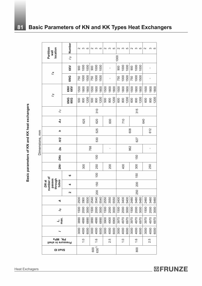
Heat Exchagers
Basic
para
mete
rs o
f K
N a
nd
KK
heat
exch
an
gers
l 2l k
Shell ID
l
L,
max.
l 0
А
24
6
DN
2
Dk
Н/2
hА
0l 1
КN
G
КК
GК
NV
К
КV
КN
G
КК
Vl
3N
um
ber
3000
3890
1500
2500
500
1500
750
900
2
1.0
4000
4890
2000
350
0800
1800
1000
1000
3
6000
6890
3000
5500
300
625
1200
1800
1500
1000
5
3000
3890
1500
2540
500
1500
750
900
2
1.6
4000
4890
2000
3540
800
1800
1000
1000
3
6000
6890
3000
5540
250
768
620
1200
1800
1500
1000
5
3000
3900
1500
2550
500
1500
2
600
630
1)
2.5
4000
4900
2000
3550
800
1800
-
-3
6000
6900
3000
5550
200
150
100
200
100
-
530
525
600
310
1200
1800
5
3000
3970
1500
2400
600
1500
750
900
2
1.0
4000
4970
2000
3400
800
1800
1000
1000
3
6000
6970
3000
5400
400
710
1200
1800
1500
1000
5
3000
3970
1500
2480
600
1500
750
900
2
1.6
4000
4970
2000
3480
800
1800
1000
1000
3
6000
6970
3000
5480
300
962
608
1200
1800
1500
1000
5
3000
3970
1500
2460
600
1500
2
800
2.5
4000
6000
4970
6970
2000
3000
3460
5460
250
200
150
250
150
-
627
612
640
315
800
1200
1800
1800
--
1000
3 5
81 Basic Parameters of KN and KK Types Heat Exchangers
DN
1
Dim
ensi
ons,
mm
Pressure in shellPN, МPa
DN
at
nu
mb
er
of
passes
thro
ug
h t
ub
es
Part
itio
nw
all
locati
on

Technical Catalogue
Co
ntin
ua
tion
sh
ee
t
0.6
;
1.0
2)
3000
4000
6000
4200
5200
720
0
1500
2000
3000
2400
3400
5400
400
800
40
0
60
0
12
00
15
00
18
00
18
00
900
1000
1000
2
3
5
1.6
3000
4000
6000
4200
5200
7200
1500
2000
3000
2430
3430
5430
150
1162
729
760
40
0
60
0
12
00
15
00
18
00
18
00
900
1000
1000
2
3
5
10
00
2.5
3000
4000
6000
4210
5210
7210
1500
2000
3000
2400
3400
5400
300
200
150
300
250
-779
712
780
380
40
0
60
0
12
00
15
00
18
00
18
00
-
2
3 5
0.6
;
1.0
2)
4000
6000
5380
7380
2000
3000
3300
5300
500
860
70
0
12
00
3
5
1.6
4000
6000
5380
7380
2000
3000
3300
5300
400
200
1362
831
830
70
0
12
00
3
51
20
0
2.5
4000
6000
5400
7400
2000
3000
3250
5250
350
250
200
350
250
-879
812
850
450
70
0
12
00
18
00
-
1000
3
5
0.6
;
1.0
2)
500
908
990
1.6
400
250
1562
912
970
1000
14
00
2.5
6000
763
03000
5200
350
250
200
350
-
990
916
950
575
12
00
18
00
-
1000
5
1)
Shell
oute
r dia
mete
r (w
hen m
ade o
f tub
e).
2)
Condense
rs, desi
gned for
opera
tion a
t nom
inal p
ress
ure
PN
0.6
and 1
.0 М
Pа, diff
er
by
flanges,
whic
h a
re m
ounte
d o
n n
om
inal p
ress
ure
P
N 0
.6 a
nd 1
.0 М
Pа.
82 Basic Parameters of KN and KK Heat Exchangers
DN
at
nu
mb
er
of
pa
ss
es
th
rou
gh
tu
be
s
l 2
l k
Pa
rtit
ion
wa
ll
loc
ati
on
l
L,
max.
l 0
А
24
6
DN
2D
kН
/2
h
А0
l 1
КN
G
КК
GК
NV
К
КV
КN
GК
КV
l 3N
um
ber
DN
1
Dim
ensi
ons,
mm
Pressure in shellPN, МPa
Shell ID

Heat Exchagers
L
l11
DN
DB
DN
2
l0± k
l2± 3
Н/2 ± 3
Н/2 ± 3
A0 ±
6A
± 6
Dk
Dн
A1 ± 6
Н/2 ± 3
2
3
4
5
6
7
8
DN
DN1
3
2
1
l3
lk
1- distributing chamber; 2 - distributing chamber gasket; 3 - tube sheet; 4 - shell; 5 - expansion pipe; 6 - heat-transferiing tube; 7- partition wall; 8 - fixed support; 9 - removable support.
Notes:1. The draw does not specify heat exchanger design.2. k=5 mm, if the length of tubes Ј 3000 mm and k=10, if the length of tubes > 3000 mm.3. Dimensions l1, L, lk, Dk are recommended, specified at detailed documentation development.
83 IN-1, IК-1 Types Heat Exchangers

Technical Catalogue
l1
1
DN
1
A0 ±
6
2
3
4
Н/2 ± 3
DB
5
Dk6
L
A ±
67lk
8
A1 ± 6
Dн
3
2
1
l - k
l2 ±
3
Н/2 ± 3
Н/2 ± 3
DN
DN
2
l3
DN1
1- distributing chamber; 2 - distributing chamber gasket; 3 - tube sheet; 4 - shell; 5 - expansion pipe; 6 - heat-transferiing tube; 7- partition wall; 8 - fixed support; 9 - removable support.
Notes:1. The draw does not specify heat exchanger design.2. k=5 mm, if the length of tubes Ј 3000 mm and k=10, if the length of tubes > 3000 mm.3. Dimensions l1, L, lk, Dk are recommended, specified at detailed documentation development.
84 IN-2, IК-2 Heat Exchangers

Heat Exchagers
Basic
para
mete
rs o
f IN
an
d IK
heat
exch
an
gers
А
А
0
D
N
des
ign
12
lL
,m
ax.
12
12
12
DN
2Н
/2l
1l
2l k
l 3N
umbe
rl 3
1.0
595
300
1200
1500
1800
700
900
1000
4
8
10
2 2 3
600
1.6
540
585
250
762
1200
1500
1800
700
900
1000
4
8
10
2 2 3
630
1)
2.5
575
595
--
1200
1500
1800
--
4
8
10
2 2 3
4.0
605
620
200
200
100
300
530
400
1200
1500
1800
300
4
8
10
2 2 3
1.0
700
400
1200
1500
1800
700
900
1000
4
6
8
2 2 3
800
1.6
630
710
250
300
150
400
962
627
560
1200
1500
1800
700
900
1000
350
4
6
8
1000
2 2 3
85 Basic Parameters of IN and IK Heat Exchangers
DN
1D
k
2000
3000
4000
3080
4080
5080
1500
2500
3500
1500
2500
3500
2000
3000
4000
3080
4080
5080
1500
2500
3500
1540
2540
3540
2000
3000
4000
3080
4080
5080
1450
2450
3450
1520
2520
3520
2000
3000
4000
3080
4080
5080
1400
2400
3400
1490
2490
3490
2000
3000
4000
3440
4440
5440
1450
2450
3450
1410
2410
3410
2000
3000
4000
3440
4440
5440
1410
2410
3410
1440
2440
3440
Dim
ensi
ons,
mm
2000
3460
1400
1410
1200
42
2.5
3000
4460
2400
2410
1500
62
4000
5460
3400
3410
670
725
627
1800
83
2000
3520
1350
1390
1200
42
4.0
3000
4000
4520
5520
2350
3350
2390
3390
700
750
250
250
150
400
677
560
1500
1800
350
6 8
2 3
Shell ID
Pressure in shellPN, МPa
Part
itio
n w
all lo
cati
on
fo
r d
esig
n
Num
ber

Technical Catalogue
Contin
uatio
n s
heet
12
l
L,
12
12
12
l 1l 2
l k
l 3
l 3
2000
3600
1350
1390
1300
800
22
3000
4600
2350
2390
1500
900
42
0.6;
1.0
2)
4000
5600
3350
3390
720
400
1800
1000
63
2000
3600
1350
1390
1300
800
22
1.6
3000
4600
2350
2390
690
1500
900
42
4000
5600
3350
3390
730
1162
729
1800
1000
63
2000
3640
1300
1360
1300
22
2.5
3000
4640
2300
2360
1500
42
4000
5640
3300
3360
720
740
1800
--6
3
2000
3660
1250
1320
1300
22
1000
4.0
3000
4000
4660
5660
2250
3250
2320
3320
755
765
300
300
200
400
--77
9
550
1500
1800
520
4 6
2 3
0.6;
3000
4880
2200
2290
1500
900
42
1.0
2)40
0058
8032
0032
9085
050
018
0010
006
3
1.6
3000
4000
4880
5880
2200
3200
2240
3240
830
860
400
250
500
1362
831
670
1500
1800
900
1000
550
4 6
2 312
00
2.5
3000
4000
4950
5950
2200
3200
2240
3240
835
870
350
350
-87
915
00
1800
-4 6
1000
2 3
86
DN
DN
2Н
/2D
N1
Dk
А
А0
Dim
ensi
ons,
mm
0.6;
1.0
2)30
00
4000
5040
6040
2250
3250
2260
3260
88
05
00
1500
1800
900
1000
2 3
1.6
3000
4000
5040
6040
2250
3250
2230
3230
82
0
89
04
00
15
62
1500
1800
900
1000
2 31
40
0
2.5
3000
4000
5050
6050
2250
3250
2210
3210
83
09
00
35
0
25
05
00
-
99
0710
1500
1800
-
600
4
2 3
1)
Shell
oute
r dia
mete
r (w
hen m
ade o
f tub
e).
2)
Vaporize
rs, desi
gned for
opera
tion a
t nom
inal p
ress
ure
PN
0.6
and
1.0
МP
а, diff
er
by
flanges,
whic
h a
re m
ounte
d o
n n
om
inal p
ress
ure
P
N 0
.6 a
nd
1.0
МP
а.
Basic Parameters of IN and IK Heat ExchangersP
art
itio
n w
all lo
cati
on
fo
r d
esig
n
Nu
mb
er
des
ign
max
. Pressure in shell
PN, МPa
Shell ID
Nu
mb
er

Heat Exchagers
20
1.2
1.8
2.4
3,6
——
—0
.0040
0.0
019
0.0
070
159
—25
11
.01
.52
.03,1
——
—0
.0045
0.0
033
0.0
075
20
4.3
6.4
8.5
12,8
——
—0
.0136
0.0
067
0.0
124
273
—25
13
.34
.96
.610,0
——
—0
.0147
0.0
081
0.0
137
1—
9.4
12
.518
.825
.0—
—0
.0200
0.0
190
20
2—
8.5
11
.316
.922
.6—
—0
.0090
0.0
110
0.0
156
1—
7.3
9.7
14
.619
.5—
—0
.0217
0.0
278
325
—
25
2—
6.6
8.8
13
.217
.6—
—0
.0098
0.0
130
0.0
147
1—
—22
.533
.745
.067
.4—
0.0
358
0.0
448
20
2—
—20
.931
.341
.762
.6—
0.0
162
0.0
180
0.0
300
1—
—16
.825
.233
.650
.4—
0.0
375
0.0
438
426
400
25
2—
—15
.423
.130
.846
.2—
0.0
168
0.0
210
0.0
250
1—
—50
.475
.5100
.7151
.1—
0.0
802
0.0
540
2—
—47
.771
.695
.5143
.2—
0.0
370
20
4—
—43
.264
.886
.4129
.6—
0.0
162
0.0
426
0.0
480
1—
— 41
.662
.483
.2124
.8—
0.0
928
0.0
525
2—
—38
.958
.477
.9116
.8—
0.0
420
630
600
25
2
4—
—33
.650
.467
.2100
.8—
0.0
179
0.0
400
0.0
450
87 Heat-Exchange Surface of TN, TK, KhN, KhK Heat Exchangers
Sh
ell
dia
me
ter
2H
ea
t e
xc
ha
ng
e s
urf
ac
e,
m,
at
tu
be
s l
en
gth
Ou
ter
Inn
er
Tu
be
OD
Tube wall
thickness
Nu
mb
er
of
pa
ss
es
th
rou
gh
tu
be
s
10
00
15
00
20
00
30
00
40
00
60
00
90
00
1)
Cle
ar
op
en
ing
are
a o
f o
ne
pa
ss
th
rou
gh
2 t
ub
es
, m
, m
in.
Cle
ar
op
en
ing
are
a a
s t
o s
hell s
ide,
2 m
, m
in
In
pa
rtit
ion
wa
ll s
lot
Be
twe
en
p
art
itio
n
wa
lls
Heat
exch
an
ge s
urf
ace a
s t
o t
ub
es o
ute
r d
iam
ete
r an
d c
lear
op
en
ing
are
a a
s t
o t
ub
e a
nd
sh
ell
sid
e
for
TN
, T
K, K
hN
, K
hK
heat
exch
an
gers
Dim
ensi
ons,
mm

Technical Catalogue
1—
—94
.1141
.1188
.1282
.2—
0.1
498
0.0
770
2—
—9
0.5
135
.7180
.9271
.4—
0.0
706
20
4—
—83
.9125
.9167
.8254
.1—
0.0
308
0.0
693
0.0
700
1—
—74
.4111
.6148
.8223
.3—
0.1
659
0.0
788
2—
—70
.8106
.2141
.6212
.4—
0.0
774
—800
25
4—
—64
.596
.8129
.1193
.6—
0.0
329
0.0
662
0.0
700
1—
——
224
.0298
.7448
.0672
.00.2
378
0.1
560
2—
——
216
.8289
.1433
.7650
.40
.1138
20
4—
——
205
.0273
.3410
.0615
.00
.0512
0.1
048
0.1
248
1—
——
181
.6242
.1363
.1544
.70
.2695
0.1
414
2—
——
174
.5232
.7349
.0523
.50
.1257
—1000
25
4—
—162
.3216
.3324
.5486
.80
.0553
0.1
062
0.1
300
1—
——
—432
.3648
.5972
.70
.3442
0.1
870
2—
——
—421
.5632
.3948
.40
.1658
20
4—
——
—401
.9602
.9904
.30
.0788
0.1
495
0.1
760
1—
——
—349
.8524
.7787
.00
.3899
0.1
788
2—
——
—338
.8508
.2762
.30
.1834
—1200
2
4—
——
—319
.3479
.0718
.50
.0854
0.1
640
25
0.1
650
—
1)
Cle
ar
openin
g a
rea is
speci
fied in
the r
ow
0 for
one-p
ass
thro
ugh tubes
heat exc
hangers
and in
row
1 f
or
2-
and 4
-pass
heat
exc
hangers
.
Note
s:
1. O
ne-p
ass
thro
ugh tubes
hea
t exc
hangers
should
be a
pplie
d o
nly
for
TN
and T
K h
eat exc
hangers
with
shell
dia
mete
r 159 -
1200 m
m
and for
KhK
heat exc
hangers
with
shell
dia
mete
r 159 a
nd 2
73 m
m.
2. T
ube o
ute
r dia
mete
r 20 m
m s
hould
be a
pplie
d for
TN
and T
K h
eat exc
hangers
.
Sh
ell
dia
me
ter
2H
ea
t e
xc
ha
ng
e s
urf
ac
e,
m,
at
tu
be
s l
en
gth
Ou
ter
Inn
er
Tu
be
OD
Tube wall
thickness
Nu
mb
er
of
pa
ss
es
th
rou
gh
tu
be
s
10
00
15
00
20
00
30
00
40
00
60
00
90
00
1)
Cle
ar
op
en
ing
are
a o
f o
ne
pa
ss
th
rou
gh
2 t
ub
es
, m
, m
in.
Cle
ar
op
en
ing
are
a a
s t
o s
hell s
ide,
2 m
, m
in
In
pa
rtit
ion
wa
ll s
lot
Be
twe
en
p
art
itio
n
wa
lls
Contin
uatio
n s
heet
Dim
ensi
ons,
mm
88 Heat-Exchange Surface of TN, TK, KhN, KhK Heat Exchangers

Heat Exchagers
25
5.8
17
4.4
2
111
.63
0.0
37
7
44
7.8
16
3.7
4
95
.62
0.0
14
21
.0;
1.6
64
5.4
56
0.6
0
90
.90
0.0
08
7
25
8.4
07
7.8
7
11
6.8
10
.04
15
45
0.4
06
7.2
0
10
0.7
90
.01
80
63
06
00
2.5
64
8,0
46
4,0
6
96
.08
0.0
10
7
21
02
.91
13
7.2
2
20
5.8
30
.07
16
49
3.4
91
24
.66
1
87
.00
0.0
32
81
.0
69
0.2
01
20
.26
1
80
.39
0.0
18
0
21
06
.21
14
1.6
1
21
2.4
20
.07
65
49
6.7
91
29
.05
1
93
.58
0.0
33
2
—8
00
1.6
; 2.5
69
3.4
91
24
.66
1
86
.99
0.0
22
2
21
74
.51
23
2.6
7
34
9.0
10
.12
42
41
62
.26
21
6.3
5
32
4.5
20
.05
57
—1
00
0
25
2
0.6
; 1.0
1.6
; 2.5
61
56
.61
20
8.8
1
31
3.2
20
.03
63
89D
imensi
ons,
mm
Heat
exch
an
ge s
urf
ace a
s t
o t
ub
es o
ute
r d
iam
ete
r an
d c
lear
op
en
ing
are
a a
s t
o t
ub
e a
nd
sh
ell
sid
e
for
KN
an
d K
K, h
eat
exch
an
gers
Heat-Exchange Surface of KN and KK Heat Exchangers
Sh
ell d
iam
ete
r
ou
ter
inn
er
Ou
ter
tub
e
dia
mete
r
Tu
be
wa
ll t
hic
kn
es
s
Pre
ss
ure
in s
he
ll,
PN
MP
a,
ma
x.
30
00
4000
6000
Nu
mb
er
of
pa
ss
es
th
rou
gh
tu
be
s
Cle
ar
op
en
ing
are
a o
f o
ne
pa
ss
th
rou
gh
2 t
ub
es
, m
, m
in.
2H
ea
t e
xc
ha
ng
e s
urf
ac
e,
m,
at
tu
be
s l
en
gth

Technical Catalogue
Contin
uatio
n s
heet
2—
332
.53
498
.79
0.1
744
4—
313
.06
469
.59
0.0
790
0.6
; 1.0
6—
305
.52
458
.28
0.0
453
2—
338
.81
508
.21
0.1
814
4—
319
.34
479
.01
0.0
861
—1200
1.6
; 2.5
6—
311
.80
467
.70
0.0
523
2—
— 706
.03
0.2
527
4—
— 671
.18
0.1
111
0.6
; 1.0
6—
— 657
.00
0.0
727
2—
— 716
.39
0.2
603
4—
— 681
.54
0.1
187
—1400
25
2
1.6
; 2.5
6—
— 667
.41
0.0
803
90D
imensi
ons,
mm
Heat-Exchange Surface of KN and KK Heat ExchangersS
hell d
iam
ete
r
ou
ter
inn
er
Ou
ter
tub
e
dia
mete
r
Tu
be
wa
ll t
hic
kn
es
s
Pre
ss
ure
in s
he
ll,
PN
MP
a,
ma
x.
30
00
4000
6000
Nu
mb
er
of
pa
ss
es
th
rou
gh
tu
be
s
Cle
ar
op
en
ing
are
a o
f o
ne
pa
ss
th
rou
gh
2 t
ub
es
, m
, m
in.
2H
ea
t e
xc
ha
ng
e s
urf
ac
e,
m,
at
tu
be
s l
en
gth

Heat Exchagers
IN -
1
IК -
1
1.0
; 1.6
;
2.5
; 4.0
41
.61
62
.41
83
.21
0.0
917
0.0
397
0.0
525
1.0
; 1.6
39
.88
59
.82
79
.76
0.0
879
——
630
600
2.5
; 4.0
41
.60
62
.41
83
.21
0.0
917
——
1.0
; 1.6
;
2.5
; 4.0
74
.42
111
.63
148
.84
0.1
641
0.0
652
0.0
788
1.0
72
.22
108
.33
144
.44
0.1
592
——
—800
1.6
; 2.5
;
4.0
74
.42
111
.63
148
.84
0.1
641
——
0.1
430
—1000
25
2
0.6
; 1.0
1.6
; 2.5
;
4.0
120
.89
181
.34
241
.78
0.2
665
0.1
065
—
91D
imensi
ons,
mm
Heat-Exchange Surface of IN and IK Heat Exchangers
Heat
exch
an
ge s
urf
ace a
s t
o t
ub
es o
ute
r d
iam
ete
r an
d c
lear
op
en
ing
are
a a
s t
o t
ub
e a
nd
sh
ell
sid
e
for
IN a
nd
IK
h
eat
exch
an
gers
IN -
1
IК -
1
IN -
1
IК -
1
IN -
2
IК -
2
IN -
2
IК -
2
IN -
2
IК -
2
Heat
exch
an
ger
desig
nati
on
2000
3000
4000
Sh
ell
dia
mete
r
ou
ter
inn
er
Ou
ter
tub
e d
iam
ete
r
Tu
be
wa
ll t
hic
kn
es
s
Pre
ss
ure
in s
he
ll,
PN
MP
a,
ma
x.
He
at
ex
ch
an
ge
su
rfa
ce
, 2
m,
at
tu
be
s l
en
gth
Cle
ar
op
en
ing
are
a o
f o
ne
pa
ss
th
rou
gh
2 t
ub
es
, m
, m
in.
Cle
ar
op
en
ing
are
a a
s t
o s
hell s
ide,
2 m
, m
in
In
pa
rtit
ion
wa
ll s
lot
Be
twe
en
p
art
itio
n
wa
lls

Technical Catalogue
0.6
; 1.0
;174
.89
262
.35
349
.80
0.3
856
0.1
640
0.1
788
0.6
; 1.0
;171
.76
257
.64
343
.52
0.3
78
——
—1200
1.6
; 2.5
174
.89
262
.35
349
.80
0.3
856
——
0.6
; 1.0
; 1
.6; 2.5
245
.23
367
.85
490
.47
0.5
406
0.1
355
0.2
250
0.6
; 1.0
241
.78
362
.67
483
.56
0.5
330
——
—1400
25
2
1.6
; 2.5
245
.23
367
.85
490
.47
0.5
406
——
Contin
uatio
n s
heet
1) C
lear
openin
g a
rea b
etw
een p
art
ition w
alls
is s
peci
fied in the r
ow
0
Note
s:1. H
eat e
xchange s
urf
ace
is g
iven w
ithou
t thic
kness
of t
ube s
heets
.
2. T
K K
hK
, KK
, IK
heat e
xchangers
to b
e u
sed to
the p
ress
ure
PN
≤1.6
МP
а.
92D
imensi
ons,
mm
Heat-Exchange Surface of IN and IK Heat Exchangers
IN -
1
IК -
1
IN -
1
IК -
1
IN -
2
IК -
2
IN -
2
IК -
2
Heat
exch
an
ger
desig
nati
on
2000
3000
4000
Sh
ell
dia
mete
r
ou
ter
inn
er
Ou
ter
tub
e d
iam
ete
r
Tu
be
wa
ll t
hic
kn
es
s
Pre
ss
ure
in s
he
ll,
PN
MP
a,
ma
x.
He
at
ex
ch
an
ge
su
rfa
ce
, 2
m,
at
tu
be
s l
en
gth
Cle
ar
op
en
ing
are
a o
f o
ne
pa
ss
th
rou
gh
2 t
ub
es
, m
, m
in.
Cle
ar
op
en
ing
are
a a
s t
o s
hell s
ide,
2 m
, m
in
In
pa
rtit
ion
wa
ll s
lot
Be
twe
en
p
art
itio
n
wa
lls

Heat Exchagers
Ma
teri
als
fo
r h
ea
t e
xc
ha
ng
ers
as
se
mb
ly u
nit
s m
an
ufa
ctu
rin
g
sh
ell
dis
trib
uti
ng
ch
am
be
rtu
be
stu
be s
heet
Kh
КК
К
М3
Bra
ss Л
АМ
ш 7
7-2
-0,0
5a
s t
o G
OS
T 2
16
46
Ste
el 1
6ГС
as t
o G
OS
T 5
52
0G
OS
T 8
47
9 (
gro
up
IV
with
ЛО
-62
-1 o
r Л
63
bra
ss f
acin
ga
s t
o G
OS
T 1
55
27
)
ТN
, Т
К,
Kh
N,
Kh
К,
КN
, К
К,
IN,
IК
М1
Ste
el o
f g
rad
es 1
0 a
nd
20
as t
o G
OS
T 8
73
1(g
rou
p B
)***
Ste
el С
т3
сп5
as t
o G
OS
T 1
46
37
Ste
el 0
9Г2
as t
o G
OS
T 5
52
0
Ste
el o
f g
rad
es 1
0 a
nd
20
as t
oG
OS
T 8
73
3 (
gr.
B)
an
dG
OS
T 5
50
(g
r. A
) o
r e
lectr
ic w
eld
ed
tu
be
s a
s t
oTe
ch
nic
al D
ocu
me
nts
ap
pro
ve
din
acco
rda
nce
with
esta
blis
he
dp
roce
du
re
Ste
el o
f g
rad
e 2
0 a
s t
o G
OS
T1
05
0 a
nd
GO
ST
84
79
(g
r IV
)***
Ste
el 1
6ГС
as t
o G
OS
T 5
52
0G
OS
T 8
47
9 (
gro
up
IV
)
М
8
Ste
el 1
2Х
18
Н1
0Т
as t
o G
OS
T 9
94
0**
*
Ste
el 1
2Х
18
Н1
0Т
as t
o G
OS
T 5
63
2a
nd
GO
ST
73
50
Ste
el 0
8Х
18
Н1
0Т, 1
2Х
18
Н1
0Т
as t
o G
OS
T 9
94
1o
r e
lectr
ic w
eld
ed
tu
be
s a
s t
oTe
ch
nic
al D
ocu
me
nts
ap
pro
ve
din
acco
rda
nce
with
esta
blis
he
dp
roce
du
re
Ste
el 1
2Х
18
Н1
0Т
as
to G
OS
T 5
632 a
nd G
OS
T 7
350
(goup М
2б
) G
OS
T 2
5054 (
gro
up IV
)and T
ech
nic
al D
ocu
ments
appro
ved
in a
ccord
ance
with
est
ablis
hed
pro
cedure
М
9
Ste
el 1
0Х
17
Н1
3М
2Т
as t
o G
OS
T 9
94
0**
*
Ste
el 1
0Х
17
Н1
3М
2Т
as t
o G
OS
T 5
63
2a
nd
GO
ST
73
50
(g
ou
p М
2б
)
Ste
el 1
0Х
17
Н1
3М
2Т
as t
o G
OS
T 9
94
1
Ste
el 1
0Х
17Н
13М
2Т
as
to G
OS
T 5
632 a
nd G
OS
T 7
350
(goup М
2б
) G
OS
T 2
5054 (
gro
up IV
)and T
ech
nic
al D
ocu
ments
appro
ved
in a
ccord
ance
with
est
ablis
hed
pro
cedure
М1
0
Ste
el 1
2Х
18
Н1
0Т
as t
o G
OS
T 9
94
0 *
**
Ste
el 1
0Х
17
Н1
3М
2Т
as t
o G
OS
T 5
63
2 a
nd
GO
ST
73
50
(g
ou
p М
2б
)
Ste
el 0
8Х
22Н
6Т
as
to G
OS
T 5
632 a
nd G
OS
T 7
350
(goup М
2б
) G
OS
T 2
5054 (
gro
up IV
)and T
ech
nic
al D
ocu
ments
appro
ved
in a
ccord
ance
with
est
ablis
hed
pro
cedure
М11
Ste
el 10
Х1
7Н
13
М2
Тa
s t
o G
OS
T 9
94
0**
*
Ste
el o
f g
rad
es 1
0a
nd
20
as t
o G
OS
T8
73
1 (
gro
up
B)*
**
Ste
el В
Ст 3
сп5
as t
o G
OS
T 3
80
***
He
at
ex
ch
an
ge
r t
yp
e
He
at
ex
ch
an
ge
rm
ate
ria
ld
es
ign
93 Materials for Heat Exchangers Manufacturing
He
at
exch
an
ge s
urf
ace a
s t
o t
ub
es o
ute
r d
iam
ete
r an
d c
lear
op
en
ing
are
a a
s t
o t
ub
e a
nd
sh
ell s
ide f
or
TN
, T
K, K
hN
an
d K
hK
h
eat
exch
an
gers
Ste
el 1
0Х
17
Н1
3М
2Т
as t
o G
OS
T 5
63
2 a
nd
GO
ST
73
50
(g
ou
p М
2б
)
Ste
el С
т3
сп5
as t
o G
OS
T 1
46
37
Ste
el 0
9Г2
as t
o G
OS
T 5
52
0
Ste
el o
f g
rad
es 1
0 a
nd
20
as t
o G
OS
T8
73
1 (
gro
up
B)*
**
Ste
el С
т3
сп5
as t
o G
OS
T 1
46
37
Ste
el 0
9Г2
as t
o G
OS
T 5
52
0
Ste
el 0
8Х
18
Н1
0Т, 1
2Х
18
Н1
0Т
as t
o G
OS
T 9
94
1o
r e
lectr
ic w
eld
ed
tu
be
s a
s t
oTe
ch
nic
al D
ocu
me
nts
ap
pro
ve
din
acco
rda
nce
with
esta
blis
he
dp
roce
du
re
Ste
el 0
8Х
18
Н1
0Т
as t
o G
OS
T 9
94
1
Ste
el 1
0Х
17Н
13М
2Т
as
to G
OS
T 5
632 a
nd G
OS
T 7
350
(goup М
2б
) G
OS
T 2
5054 (
gro
up IV
)and T
ech
nic
al D
ocu
ments
appro
ved
in a
ccord
ance
with
est
ablis
hed
pro
cedure
ТN
, Т
К,
Kh
N,
Kh
К,
КN
, К
К,
IN,
IК
ТN
, Т
К,
IN,
IК
ТN
, Т
К,
IN,
IК

Technical Catalogue
He
at
exch
an
ge s
urf
ace a
s t
o t
ub
es o
ute
r d
iam
ete
r an
d c
lear
op
en
ing
are
a a
s t
o t
ub
e a
nd
sh
ell s
ide f
or
TN
, T
K, K
hN
an
d K
hK
h
eat
exch
an
gers
Contin
uatio
n s
heet
Ma
teri
als
fo
r h
ea
t e
xc
ha
ng
ers
as
se
mb
ly u
nit
s m
an
ufa
ctu
rin
g
He
at
ex
ch
an
ge
r t
yp
e
He
at
ex
ch
an
ge
rm
ate
ria
ld
es
ign
s
he
ll
dis
trib
uti
ng
ch
am
be
rtu
be
s tu
be
sh
ee
t
ТN
, Т
К,
Kh
N,
Kh
K,
KN
, K
K
М
12
Ste
el С
т3
сп a
s t
oG
OS
T 3
80
, G
OS
T 1
46
37
Ste
el 0
9Г2
Сa
s t
o G
OS
T 5
52
0
Tu
be
s -
ste
el g
rad
e 2
0 a
sto
GO
ST
10
50
, G
OS
T8
73
1 (
gro
up
B)
1)
Ste
el С
т3
сп,
Ст3
сп
as t
o G
OS
T 3
80
,2
)1
46
37
Ste
el 0
9Г2
Сa
s t
o G
OS
T 5
52
0T
ub
es -
ste
el g
rad
e 2
0a
s t
o G
OS
T 1
05
0,
GO
ST
87
31
(g
rou
p B
)
3)
Ste
el 0
8Х
22
Н6
Т, 1
2х1
8Н
10
Т a
s t
o
GO
ST
56
32
, G
OS
T 9
94
1
Ste
el 1
6ГС
as t
oG
OS
T 5
52
0,
GO
ST
84
79
ТN
, Т
К,
IN,
IK
М1
7
S
tee
l 1
0Г2
as t
o G
OS
T 5
50
3)
(g
rou
p А
), G
OS
T 8
73
3
(gro
up
B)
Ste
el 0
9Г2
С a
nd
10
Г2
С1
as t
o G
OS
T 5
52
0,
09
Г2
С a
nd
10
Г2
as t
o G
OS
T4
79
(g
rou
p I
V)
М1
9
Ste
el 0
8Х
22
Н6
Т a
s t
o G
OS
T 5
63
2 a
nd
GO
ST
73
50
(g
ou
p М
2б
)
М
20
Ste
el 1
0Х
17
Н1
3М
2Т
as t
o G
OS
T 9
94
1
М2
1
ТN
, Т
К
М2
2
Ste
el 0
8Х
21
Н6
М2
Тa
s t
o G
OS
T 5
63
2 a
nd
Te
ch
nic
al D
ocu
me
nts
ap
pro
ve
din
acco
rda
nce
with
esta
blis
he
dp
roce
du
re
* T
o b
e a
pplie
d fo
r heat e
xchangers
and v
aporize
rs**
T
o b
e a
pplie
d o
nly
for h
eat e
xchangers
*** To
be a
pplie
d o
nly
for T
N, T
K, K
hK
heat e
xch
angers
of 1
59, 2
73, 3
25 m
m d
iam
ete
r, fo
r М9, М
11 d
esi
gn o
f 59 m
m d
iam
ete
r (K
hK
on
ly fo
r М3
de
sig
n).
Note
s: It
is a
llow
ed to
pro
duce
com
ponents
and p
art
s of a
noth
er m
ate
rial g
rades
whic
h m
atc
h m
ech
anic
al p
ropert
ies
an
d c
orr
osi
on
re
sist
an
ce o
f ma
teria
ls w
hic
h a
re in
the
t
able
.
94 Materials for Heat Exchangers Manufacturing
ТN
, Т
К,
Kh
N,
Kh
K,
KN
, K
K
Ste
el 0
9Г2
С a
s t
o G
OS
T 5
52
0T
ub
es -
ste
el 1
0Г2 a
s t
o G
OS
T 8
73
1 (
gr.
B)
an
d0
9Г2
С a
s t
o T
ech
nic
al D
ocu
me
nts
ap
pro
ve
din
acco
rda
nce
with
esta
blis
he
d p
roce
du
re
Ste
el 0
8Х
22
Н6
Т a
s t
o G
OS
T 5
63
2 a
nd
GO
ST
73
50
(g
ou
p М
2б
)
Ste
el 0
8Х
22
Н6
Т a
s t
o
GO
ST
56
32
an
d G
OS
T 7
35
0 (
go
up
М2
б)
Ste
el 0
8Х
22
Н6
Т a
s t
o G
OS
T 5
63
2 a
nd
G
OS
T 7
35
0 (
go
up
М2
б)
Ste
el С
т3
сп a
s t
o
GO
ST
14
63
7S
tee
l 0
9Г2
С**
as t
o G
OS
T 5
52
0
Ste
el 0
8Х
18
Н1
0Т, 1
2Х
18
Н1
0Т
as t
o G
OS
T 9
94
1o
r e
lectr
ic w
eld
ed
tu
be
s a
s t
oTe
ch
nic
al D
ocu
me
nts
ap
pro
ve
din
acco
rda
nce
with
esta
blis
he
dp
roce
du
re
Ste
el 0
8Х
22
Н6
Т a
s t
o
GO
ST
56
32
, G
OS
T 9
94
1
Ste
el 0
8Х
22
Н6
Т a
s t
o
GO
ST
56
32
, G
OS
T 9
94
1
Ste
el 0
8Х
21Н
6М
2Т
as
to G
OS
T 5
632
and T
ech
nic
al D
ocu
ments
appro
ved
in a
ccord
ance
with
est
ablis
hed
pro
cedure
Ste
el 08Х
22Н
6Т
as to
GO
ST
5632 a
nd G
OS
T 7
350
(goup М
2б
) G
OS
T 2
5054 (
gro
up IV
)and T
echnic
al D
ocum
ents
appro
ved
in a
ccord
ance w
ith e
sta
blis
hed
pro
cedure
S
teel 08Х
21Н
6М
2Т
as to
GO
ST
5632 a
nd G
OS
T 7
350
(goup М
2б
) G
OS
T 2
5054 (
gro
up IV
)and T
echnic
al D
ocum
ents
appro
ved
in a
ccord
ance w
ith e
sta
blis
hed
pro
cedure

Heat Exchagers
Weig
ht
of
TN
, T
K h
eat
exch
an
gers
Sh
ell d
iam
ete
rTu
bes 2
0 х
2 w
ith
len
gth
Tu
be 25 х
2 w
ith
len
gth
1000
1500
2000
3000
4000
1000
1500
2000
3000
4000
ou
ter
inn
er
Pre
ssu
re in
sh
ell a
nd
tu
bes
PN
, М
Pа, m
ax.
Esti
mate
d w
eig
ht,
kg
1 p
ass
1.6
145
170
190
245
-
135
165
185
23
5-
2.5
175
200
220
275
-
170
190
210
25
5-
159
-
4.0
175
200
220
275
-
170
190
210
25
5-
1 p
ass
1.6
295
365
345
575
-
275
345
410
535
-
2.5
355
425
495
630
-
345
415
475
600
- 273
-
4.0
430
54
0
575
710
-
405
470
535
670
-
1 p
ass
1.6
-465
530
665
800
-
435
495
610
720
2.5
-54
0
605
740
900
-
510
570
690
820
4.0
-65
0
720
880
990
-
565
680
800
910
2 p
asses
1.6
-44
0
500
620
745
-
415
465
57
5680
2.5
-51
0
570
700
820
-
480
535
645
750
325
-
4.0
-605
660
810
950
-
575
625
730
900
95 Weight of TN, TK Heat Exchangers
Dim
ensi
ons, m
m

Technical Catalogue
Contin
uatio
n s
heet
Sh
ell d
iam
ete
rTu
be 2
0 х
2 w
ith
len
gth
Tu
be 2
5 х
2 w
ith
len
gth
2000
30
00
4
000
6
000
9
000
2
000
30
00
4
000
6
000
9
000
o
ute
r
inn
er
E
sti
mate
d w
eig
ht,
kg
1 p
ass
1.6
860
11
30
143
0
1850
-
780
1
030
1
290
1750
-
2.5
980
123
0
1540
1960
-
870
1
14
0
140
0
1860
-
4.0
1
090
1
29
0
178
0
2120
-
103
0
120
0
1480
19
40
-
1 p
ass
1.6
860
11
30
1360
1930
-
790
1020
134
0
1660
-
2.5
1020
1
25
0
149
0
202
0
- 960
11
80
1380
186
0
-
426
400
4.0
11
50
1
47
0
1660
224
0
- 1
080
135
0
15
10
213
0
-
1 p
ass
1.6
1570
2030
254
0
35
40
-
1360
1840
2
45
0
3190
-
2.5
1710
225
0
27
60
38
40
-
1550
2020
2560
3480
-
4.0
2100
267
0
3530
43
80
-
1970
2470
339
0
395
0
-
2 p
asses
1.6
1520
192
0
2350
3470
-
1350
1820
2190
2910
-
2.5
1870
240
0
292
0
398
0
- 1710
219
0
2640
3550
-
4.0
2430
30
00
356
0
469
0
- 2290
2800
3280
427
0
-
4
passes
1.6
1530
188
0
228
0
33
20
-
1360
1780
2130
2
760
-
2.5
1880
236
0
285
0
383
0
- 1720
215
0
25
80
3
400
-
630
600
4.0
2440
29
60
349
0
454
0
- 2300
2
760
3
220
412
0
-
96P
ressu
re in
sh
ell a
nd
tu
bes
PN
, М
Pа, m
ax.
Dim
ensi
ons,
mm
Weight of TN, TK Heat Exchangers

Heat Exchagers
Contin
uatio
n s
heet
Tu
be
20
х 2
wit
h l
en
gth
Tu
be
s 2
5 х
2 w
ith
le
ng
th
20
00
30
00
40
00
60
00
90
00
20
00
30
00
40
00
60
00
90
00
Sh
ell
ID
Es
tim
ate
d w
eig
ht,
kg
1 p
as
s
1.0
26
40
35
70
43
10
60
40
- 2
30
03
16
03
76
05
42
0-
1.6
27
80
36
40
45
60
63
40
- 2
32
03
28
04
04
05
46
0-
2.5
31
90
41
50
511
07
04
0-
29
20
37
30
45
70
63
50
-
4.0
39
30
49
70
60
20
811
0-
36
60
46
00
54
70
70
70
-
2
pa
ss
es
1.0
26
80
35
10
43
50
60
40
- 2
52
03
24
03
96
05
38
0-
1.6
28
80
37
60
46
50
63
40
- 2
72
03
45
04
18
05
62
0-
2.5
31
80
41
60
51
00
70
00
- 2
87
03
68
04
50
06
12
0-
4.0
41
60
511
06
07
08
01
0-
40
80
47
40
56
90
73
40
-
4
pa
ss
es
1.0
27
40
35
10
43
20
59
20
- 2
56
03
26
03
93
05
26
0-
1.6
29
40
37
90
46
20
61
90
- 2
79
03
47
04
15
05
50
0-
2.5
32
40
41
60
50
70
68
80
- 2
94
03
70
04
47
06
00
0-
8
00
4.0
42
20
51
40
60
40
78
90
- 4
15
04
76
05
66
07
22
0-
1
pa
ss
0.6
-5
02
06
49
09
00
01
29
80
- 4
41
05
46
07
87
011
25
0
1.0
-5
22
06
56
09
21
01
31
80
- 4
54
05
77
07
97
011
40
0
1.6
-5
60
06
79
09
87
01
37
50
- 4
89
06
16
08
37
01
20
50
2.5
-6
10
07
57
01
05
30
15
18
0-
55
10
67
90
92
70
13
35
0
4.0
-7
110
89
40
12
18
0-
- 6
78
08
19
011
01
0-
2
pa
ss
es
0.6
-5
05
06
29
08
77
01
29
20
- 4
48
05
59
07
81
011
15
0
1.0
-5
23
06
54
09
18
01
31
20
- 4
58
05
71
07
97
011
35
0
1.6
-5
52
06
90
09
66
01
36
90
- 4
93
06
110
83
70
119
50
2.5
-6
17
07
58
01
03
90
15
12
0-
54
30
68
00
91
20
13
20
0
10
00
4.0
-7
71
09
27
01
23
80
- -
77
50
89
50
116
50
-
97P
ressu
rein
sh
ell
an
d t
ub
es
PN
, М
Pа,
max.
Dim
ensi
ons,
mm
Weight of TN, TK Heat Exchangers

Technical Catalogue
Tu
be 2
0 х
2 w
ith
len
gth
Tu
be
s 2
5 х
2 w
ith
le
ng
th
20
00
30
00
40
00
60
00
90
00
20
00
30
00
40
00
60
00
90
00
Sh
ell
ID
Es
tim
ate
d w
eig
ht,
kg
4
pa
ss
0.6
- 5
07
06
25
08
64
01
26
10
-
42
50
55
70
7
67
0
10
83
0
1.0
- 5
25
06
50
09
05
01
28
10
-
46
20
56
90
7
83
0
110
30
1.6
- 5
54
06
86
09
53
01
33
80
-
49
70
60
90
8
23
0
116
30
2.5
- 6
39
07
54
01
02
60
14
81
0
-5
47
06
78
0
89
80
1
28
80
4.0
- 7
91
09
49
01
26
00
- -
74
50
87
80
11
44
0-
1
pa
ss
0.6
- -
89
30
12
76
01
86
50
-
-7
91
0
111
90
16
08
0
1.0
- -
91
80
12
91
01
89
70
-
-8
21
0
113
60
16
28
0
1.6
- -
93
10
13
10
01
93
60
-
-8
46
0
117
80
16
73
0
10
00
2.5
- -
110
30
15
22
02
18
90
-
-9
91
0
13
59
01
98
10
2 p
as
se
s
0.6
- -
90
30
12
75
01
85
60
-
-8
00
0
111
20
15
85
0
1.0
- -
96
50
13
36
01
91
70
-
-8
35
0
115
00
16
25
0
1.6
- -
96
80
13
74
01
93
10
-
-8
60
0
117
70
16
60
0
2.5
- -
114
50
14
80
02
18
60
-
-1
01
00
1
36
70
19
10
0
4
pa
ss
es
0.6
- -
90
90
12
66
01
82
80
-
-8
04
0
110
20
15
53
0
1.0
- -
97
10
13
29
01
88
90
-
-8
39
0
114
00
15
93
0
1.6
- -
97
40
13
39
01
90
30
-
-8
64
0
116
70
16
28
0
12
00
2.5
- -
115
10
14
72
02
15
80
-
-1
01
40
1
35
70
18
78
0
Contin
uatio
n s
heet
98P
ressu
rein
sh
ell
an
d t
ub
es
PN
, М
Pа,
max.
Dim
ensi
ons,
mm
Weight of TN, TK Heat Exchangers

Heat Exchagers
Weig
ht
of
Kh
Km
Kh
N h
eat
exch
an
gers
Sh
ell d
iam
ete
r Tu
bes 2
5 х
2 w
ith
len
gth
1500
2000
300
04000
6000
9000
ou
ter
ste
el
bra
ss
ste
el
bra
ss
ste
el
bra
ss
ste
el
bra
ss
ste
el
bra
ss
ste
el
bra
ss
1 p
ass
1)
159
--
200
-
220
-
280
- -
- -
--
1 p
ass
1)
273
-
-380
-
450
-
580
- -
- -
--
2 p
asses
1)
325
-
-470
-
530
-
670
- -
- -
--
2 p
asses
1)
426
400
1. 6
--
- 860
-
1080
- 1340
- 1780
--
2 p
asses
1.0
--
1490
1550
1910
1990
2310
24
20
3170
3350
--
1.6
--
1580
1640
2030
211
02440
2550
3300
3420
--
2.5
--
1610
-
2170
-
2680
- 3540
-
--
4.0
--
1960
-
2520
-
2930
- 3900
-
--
4 p
asses
1.0
-
- 1480
1540
1870
1930
2230
2320
3010
3170
--
1.6
-
- 1570
1630
1990
2050
2360
2450
3140
3240
--
2.5
-
- 1600
-
2130
-
2600
- 3380
-
--
630
600
4.0
-
- 1950
-
2480
-
2850
- 3740
-
--
inn
er
99D
imensi
ons,
mm
Weight of KhK, KhN Heat Exchangers
Pre
ssu
rein
sh
ell
an
d
tub
es
PN
, М
Pа,
max.
Es
tim
ate
d w
eig
ht,
kg

Technical Catalogue
Contin
uatio
n s
heet
Tu
bes 2
5 х
2 w
ith
len
gth
1500
2000
3000
4000
6000
9000
Esti
mate
d w
eig
ht,
kg
ste
el
bra
ss
ste
el
bra
ss
ste
el
bra
ss
ste
el
bra
ss
ste
el
bra
ss
ste
el
bra
ss
2 p
asses
1.0
- -
2540
2580
3270
3480
4000
4130
5430
5530
--
1.6
- -
2720
2820
3520
3590
4200
4290
5890
5980
--
2.5
- -
3000
- 3640
- 4450
- -
- -
-
4.0
- -
3420
- 4240
- 5100
- -
- -
-
4 p
asses
1.0
- -
2620
2630
3310
3500
3990
4100
5330
5400
--
1.6
- -
2800
2890
3560
3610
4190
4260
5790
5850
--
2.5
- -
3080
- 3680
- 4440
- 6060
- -
-
-
800
4.0
- -
3500
- 4280
- 5090
- 6620
- -
-
2 p
asses
0.6
- -
- -
4630
5040
5760
6210
8020
8560
11400
12100
1.0
- -
- -
4780
5140
5910
6330
8120
8720
11500
12300
1.6
- -
- -
4970
5310
6140
6590
8370
9060
11900
12800
2.5
- -
- -
5280
- 6490
- 8870
-
12500
-
-
1000
4.0
- -
- -
5780
- 7060
- 9650
-
--
ou
ter
inn
er
100
Dim
ensi
ons,
mm
Weight of KhK, KhN Heat Exchangers
Sh
ell d
iam
ete
r P
ressu
rein
sh
ell
an
d
tub
es
PN
, М
Pа,
max.

Heat Exchagers
1)
TN
and T
K h
eat exc
hangers
should
be
applie
d a
s K
hN
and K
hK
heat exc
hangers
wih
159, 273, 325, 400 (
426)
mm
shell
dia
mete
r and w
ith s
teel
heat t
ran
sferr
ing tu
bes.
Tu
bes 2
5 х
2 w
ith
len
gth
1500
2000
3000
4000
6000
9000
ste
el
bra
ss
ste
el
bra
ss
ste
el
bra
ss
ste
el
bra
ss
ste
el
bra
ss
ste
el
bra
ss
4 p
asses
0.6
-
--
-4650
5050
5730
6210
7870
8370
11
070
11
720
1.0
-
--
-4880
5150
5880
6330
7970
8530
11
170
11
920
1.6
-
--
-4990
5320
611
06390
8220
8870
11
570
12220
2.5
-
--
-5300
-6460
-8720
-
12170
-
4.0
-
--
-5800
-7030
-9500
-
- -
-
1000
2 p
asses
0.6
-
--
--
-8
400
9130
11
61
0
12430
16500
17400
1.0
-
--
--
-85
00
930
0
1171
0
12680
16600
17750
1.6
-
--
--
-9
000
964
0
12210
0
13040
17100
18150
2.5
-
--
--
-98
00
-13170
-
18300
-
4 p
asses
0.6
-
--
--
-843
09
130
11
500
12280
16180
17020
1.0
-
--
--
-853
09
30
0
11600
12530
16280
17370
1.6
-
--
--
-903
0967
0
12100
12890
16780
17770
-
1200
2.5
-
--
--
-983
0-
13060
-
17980
-
101D
imensi
ons,
mm
Sh
ell d
iam
ete
r
ou
ter
inn
er
Pre
ssu
rein
sh
ell
an
d t
ub
es
PN
, М
Pа,
max.
Esti
mate
d w
eig
ht,
kg
Contin
uatio
n s
heet
Weight of KhK, KhN Heat Exchangers
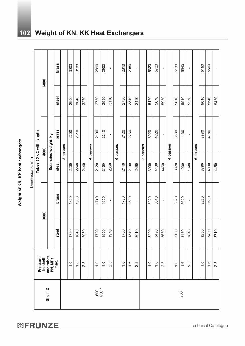
Technical Catalogue
Weig
ht
of
KN
, K
K h
eat
exch
an
gers
Tu
be
s 2
5 х
2 w
ith
le
ng
th
30
00
4
00
0
60
00
Es
tim
ate
d w
eig
ht,
kg
ste
el
bra
ss
ste
el
bra
ss
ste
el
bra
ss
2
pa
ss
es
1.0
1
76
01
80
02
20
02
20
02
90
03
00
0
1.6
1
84
01
90
02
24
02
31
03
04
03
13
0
2.5
2
03
0-
24
40
- 3
27
0-
4
pa
ss
es
1.0
1
72
01
74
02
12
02
10
02
73
02
81
0
1.6
1
80
01
85
02
16
02
21
02
88
02
95
0
2.5
1
97
0-
23
60
- 3
110
-
6
pa
ss
es
1.0
1
76
01
78
02
14
02
12
02
73
02
81
0
1.6
1
84
01
89
02
19
02
23
02
84
02
95
0
60
0 1)
63
0
2.5
2
01
0-
23
90
- 3
110
-
2
pa
ss
es
1.0
3
20
03
22
03
90
03
92
05
17
05
32
0
1.6
3
49
03
64
04
10
04
22
05
67
05
72
0
2.5
3
66
0-
44
60
- 5
93
0-
4
pa
ss
es
1.0
3
18
03
82
03
82
03
83
05
01
05
13
0
1.6
3
42
03
62
04
03
04
13
05
51
05
54
0
2.5
3
64
0-
43
90
- 5
57
0-
6
pa
ss
es
1.0
3
25
03
25
03
88
03
88
05
04
05
15
0
1.6
3
49
03
69
04
09
04
18
05
54
05
56
0
8
00
2.5
3
71
0-
44
50
- -
102 Weight of KN, KK Heat ExchangersD
ime
nsio
ns,
mm
Sh
ell
ID
Pre
ssu
re
in s
hell
an
d t
ub
es
PN
, М
Pа,
max.
54
50

Heat Exchagers
Tu
be
s 2
5 х
2 w
ith
le
ng
th
30
00
4
00
0
60
00
Es
tim
ate
d w
eig
ht,
kg
s
tee
lb
ras
ss
tee
lb
ras
ss
tee
lb
ras
s
2
pa
ss
es
0.6
46
00
47
60
57
00
59
00
78
90
82
00
1.0
47
50
48
20
58
30
59
80
79
50
83
10
1.6
50
80
52
70
62
40
64
60
85
70
88
50
2.5
53
80
- 6
57
0-
89
20
-
4
pa
ss
es
0.6
46
10
47
50
55
60
58
30
77
20
80
00
1.0
47
60
48
10
57
90
59
10
77
80
811
0
1.6
50
90
52
60
62
00
63
90
84
00
86
50
2.5
53
90
- 6
53
0-
87
50
-
6
pa
ss
es
0.6
47
20
48
50
57
00
59
00
77
50
80
10
1.0
48
70
49
10
58
50
59
80
78
10
81
20
1.6
52
00
53
60
62
60
64
60
84
30
86
60
10
00
2.5
55
00
- 6
68
0-
87
70
-
2
pa
ss
es
0.6
- -
82
00
89
80
10
95
01
20
70
1.0
- -
85
00
92
70
113
80
12
15
0
1.6
- -
89
30
98
00
117
70
12
72
0
12
00
2.5
- -
10
04
0-
12
87
0-
103D
imensi
ons,
mm
Weight of KN, KK Heat ExchangersC
ontin
uatio
n s
heet
Sh
ell
ID
Pre
ssu
re
in s
hell
an
d t
ub
es
PN
, М
Pа,
max.

Technical Catalogue
Tu
be
s 2
5 х
2 w
ith
le
ng
th
30
00
40
00
60
00
Es
tim
ate
d w
eig
ht,
kg
ste
el
bra
ss
ste
el
bra
ss
ste
el
bra
ss
4 p
as
se
s
0.6
--
82
40
89
80
10
85
011
93
0
1.0
--
85
40
92
70
112
80
12
01
0
1.6
--
89
70
97
00
115
20
12
41
0
2.5
--
10
08
0-
12
62
0-
6 p
as
se
s
0.6
--
84
40
91
70
110
00
12
06
0
1.0
--
87
40
94
60
114
30
12
14
0
1.6
--
91
70
98
90
116
70
12
54
0
12
00
2.5
--
10
28
0-
12
77
0-
2 p
as
se
s
0.6
--
--
15
94
01
65
20
1.0
--
--
16
26
01
68
00
1.6
--
--
16
83
01
73
60
2.5
--
--
17
63
0-
4 p
as
se
s
0.6
--
--
15
87
01
64
00
1.0
--
--
15
76
01
66
80
1.6
--
--
16
76
01
72
50
2.5
--
--
17
56
0-
6 p
as
se
s
0.6
--
--
16
10
01
66
10
1.0
--
--
16
42
01
68
90
14
00
1.6
--
--
16
69
01
74
50
104D
imensi
ons,
mm
Weight of KN, KK Heat ExchangersC
ontin
uatio
n s
heet
Sh
ell
ID
Pre
ss
ure
in
sh
ell
an
d t
ub
es
P
N,
МP
а,
ma
x.

Heat Exchagers
Weight of IN, IK heat exchangers
1) Outer shell diameter (to be made of tubes).
Notes:31. Heat exchangers weight is calculated for steel with density 7.85 g/cm .
2. Tolerance on weight values must not exceed +8%.
3. Heat exchangers weight is calculated for nominal thickness of heat transferring tubes and sheet metal without weight of hanging device for distributing chambers and covers to them.
Tubes 25 х 2 with length
2000 3000 4000Shell ID
1 2 1 2 1 2
1.0 1350 1330 1780 1750 2210 2170
1.6 1410 1810 2230
2.5 1520 1990 2570600
630)1
4.0 1840 2340 2930
1.0 2320 2290 3230 3190 3700 3650
1.6 2420 3380 3880
2.5 2720 3530 4340800
4.0 3170 4130 5100
0.6 3460 3420 4640 4590 5810 5740
1.0 3610 3530 4770 4720 5920 5850
1.6 3710 4840 5960
2.5 3860 5240 6410
1000
4.0 4980 6090 7450
0.6 - 6560 6490 8100 8010
1.0 - 6610 6540 8300 8210
1.6 - 6860 85001200
2.5 - 7410 9050
0.6 - 8500 10500
1.0 - 8630 10680
1.6 - 9340 114501400
2.5 - 11200 13200
105 Weight of IN, IK Heat Exchangers
Dimensions, mm
Pressure in shell and tubes PN, МPа, max. Estimated weight, for design, kg

Technical Catalogue
For supports of heat exchangers with diameter 800 mm slot in supporting plate to be 80х30 mm
І ІІ ІІІ
І ІІ ІІІ
R14 R18R14
50 8080
36
28
28
120 180140
250
A3
A3
A2 A3
Shell diameter, mm
Outer Inner
А2
159 - - 180
273 - - 290
325 - 400
426 400330
450
630 600 450 600
- 800 500 740
- 1000 650 1000
- 1200 800 1100
- 1400 950 1250
106Layout of Bolt Holes in Supports in ТN, ТК, KhN, KhK, КN, КК, IN, IК Heat Exchangers
А3
Dimensions, mm

Heat Exchagers
Layout of supports and nozzles of ТN, ТК, KhN, KhК, КN, КК, IN, IК vertical heat exchangers
А1 ±
6
А1
В
5 Іf
R
I
α
I
For ТN, ТК, KhN, КN, КК, IN, IК heat exchangers having 2 supports
For ТN, ТК, KhN, КN, КК, IN, IК one pass through tubes heat exchangers
having 4 supports
For ТN, ТК, KhN, КN, КК, IN, IК one pass through tubes heat exchangers
having 4 supports
Shell diameter
Outer Inner
Pressure in shell,PN, МPа
Tube length,l
Quantityof supports
А1 R B lf
159 322
273-
1000;1500;2000; 3000 498
40
325 -
1.6; 2.5;4.0 1500; 2000;
3000; 4000562
25
426 400
2
660
630 600
1.0; 1.6;2.5; 4.0
2000; 30004000; 6000 870
30
3000 1126 401.0; 1.6;2.5
2000; 4000; 6000 1206
12.0 24
50
45
3000; 4000 1294 17.5 35 70 55- 800
4.0 2000; 6000 1412 45
30000.6; 1.0;1.6; 2.5
2000; 4000;
6000; 9000- 1000
4.0 2000; 3000;4000; 6000
2at
l 2000
4at
l 20001496 55
3000; 4000; 6000 1704 55- 1200
0.6; 1.0;1.6; 2.5
9000 1800 70
3000; 4000 1910 55- 1400
0.6; 1.0;1.6; 2.5
6000
4
2008
21.0 42 80
70
107Layout of Supports and Nozzles in ТN, ТК, KhN, KhК, КN, КК, IN, IК Heat Exchangers
А1 ±
6
А1 ±
6А
1 ±
6
А1 ± 6
А1 ± 6
Dimensions, mm

Technical Catalogue
Limit working pressure МPа, at medium temperature, °С Nominal pressure
PN, MPa up to 100 200 250* 300* 350*
0.6 0.6 0.56 0.54 0.48 0.40
1.0 1.0 0.93 0.90 0.75 0.66
1.6 1.6 1.49 1.40 1.20 1.10
2.5* 2.5 2.32 2.25 1.90 1.70
4.0* 4.0 3.72 3.50 3.00 2.60
* Only for heat exchangers with steel tubes.
Notes: limit working pressure for heat exchangers should not exceed the limit working pressure of the materials specified in OST 26-291.
108 Limit Working Pressure for Heat Exchangers

Heat Exchagers
1.
Designation
2. Design and operating conditions Medium parameter
in tubes in shell
2.1. Pressure, МPа
Р working
Р design
2.2. Working temperature, °С
inlet
outlet
2.3. Temperature of shell walls and tubes, °С
2.4. Design temperature, °С
2.5. Minimum allowed (negative) temperature of heat exchanger wall under pressure, °С
2.6. Average air temperature of the coldest five days at heat exchanger layout (site),°С, (fill for heat exchangers to be installed outdoors or in unheated rooms)
2.7. Temperature of working medium boiling at pressure 0.07 МPа, °С
2.8. Working medium designation and percentage composition
2.9. Physical state of medium (gas, vapor, liquid)
2.10. Medium characteristics: harmfulness as to standard GOST 12.1.007 (indicating the hazard class)
flammability as to standard GOST 12.1.004 "yes", "no"
explosive hazard as to standard GOST 12.1.011 (indicating mixture category and group)
Does medium cause stress corrosion cracking "yes", "no", if “yes” testing to be fulfilled
3. Gasket material
4. Necessity of installation of parts for thermal insulation fixing "yes", "no" (delete as applicable) (parts are installed for heat exchangers with shell diameter і 500 mm)
5. Necessaty of ICC testing of base metal and welded joints “yes”, “no”, if “yes” specify procedure as to standard GOST 6032 (fill for heat exchangers where steel grade 08Х18Н10Т, 12XI8H10T, 10X17HIЗМ2Т, 08Х22Н6Т is applied)
ORDER FORMfor heat exchanger manufacturing as to Specifications TU 3612-024-00220302-02
109 Order Form for Heat Exchanger Manufacturing

Technical Catalogue
Nozzlenumber(No) on figure
6. Specify: pivot points "left", "right", "not required" (delete as applicable)(pivot points are installed on horizontal heat exchangers - Ж 400-1200 mm at Рn ≤4.0 МPа, 1400 mm at Рn ≤2.5 МPа,
7. Horizontal heat exchangers are installed:«on concrete foundation", "on metal structures"
(delete as applicable)
8. Specify type of tube fastening in sheets: "expanding",
«seal welding with expanding" (delete as applicable)
9. Seamless tubes "yes", "no" (delete as applicable)
10. Heat exchanger figure with location dimensions of nozzles and supports(for heat exchangers having differences from these specifications )
NOZZLES
Nozzles purposeNozzles
nominal diameter, mm
Nominal pressure, МPа
Notes:
1. Heat exchangers figure should correspond figure given in these Specifications ТU.
2. Dimensions are specified if they differ from the dimensions given in these Specifications TU.
3. Nozzles nominal diameters are specified if they are less than in these Specifications TU.
11. The content of adopted differences from heat exchanger prototype
(differences listed in these Specifications are allowed)
_______________________________________________________________________
_______________________________________________________________________
_______________________________________________________________________
_______________________________________________________________________
Order Form for heat exchanger manufacturing as to Specification ТU 3612-005-00220302-98is not subject to be agreed.
Name of the Company-User and process plant or line
Name and postal address of the Company that filled Order Form
Signature of the head of the Company that filled Order Form
________________ _____________________ ____________________ (Title) (Signature) (Print full name)
_____________________(Date)
110 Order Form for Heat Exchanger Manufacturing
Heat Exchagers
«Gas-Gas» TypeHeat Exchangers

Technical Catalogue
“Gas-gas” type heat-exchangers are designed for gas cooling in natural and associated petroleum gas treatment plants.
Heat exchangers can be operated in the conditions of temperate climatic region according to the Standard GOST 16350-80 with the average temperature of the coldest five-days minimum -40°С in climatic design У, placement category 1 as to Standard GOST 15150-69.
Technical requirements to materials, manufacture, acceptance, testing methods and preservation of apparatuses per SOU МPP 71.120-217:2009, GOST R 52630 and Technical Regulation of Customs Union 032/2013.
Heat exchangers are horizontal one-or two-staged counterflow shell and tubes units with U-shaped heat transferring tubes, two-passes through tube and shell side.
By design heat exchangers are divided into four types:
type 1 - one-stage without injection of hydrate inhibitor;
type 2 - one-stage with injection of hydrate inhibitor;
type 3 - two-stage without injection of hydrate inhibitor;
type 4 - two-stage with injection of hydrate inhibitor.
To prevent hydrate formation hydrate inhibitor is injected into tube side of 3 and 4 type heat exchangers, which is sprayed uniformly into all heat transferring tubes with centrifugal sprayers.
The cooled gas is supplied to the tube side and cold gas is supplied to the shell side.
Heat exchangers are manufactured of two material design:
М1 - for media with volume ratio: СO - up to 1%, 2Н S - max. 0.001 %;2
М2 - for media with volume ratio: СO - до 2%, 2Н S - max. 0.001%.2
Material of assembly units and parts: shell - steel 09Г2С; flanges, nozzles, tube sheets - forging of steel 20, 10Г2, 09Г2С; heat transferring tubes of diameter 20x2 or 20x2.5 (length of straight section 6 or 9 m) - steel 20 (material design М1) or steel 08Х22Н6Т (material design М2).
When installing heat exchangers should be thermally insulated.
Description
“Gas-gas” heat exchanger, one-stage, of diameter 2600 mm; design pressure, МPа (kgf/cm ): in tube side
16 (160); in shell side 8.8 (88); length of tube nest - 6 m; material design - М1.
“Gas-gas” heat exchanger 1-600-16/8.8-6-М1.
The same material design М2:
“Gas-gas” heat exchanger 1-600-16/8.8-6-М2.
When ordering heat exchanger product designation and Specification (ТU 26-02-928-81) should be specified after description.
112 “Gas-Gas” Type Heat Exchangers

Heat Exchagers
1-600-16/8.8-6-М1 8.8(88) 13.8(138) 8,0(80) 145 8940
1-600-16/8.8-6-М2
16(160)
1-600-16/8.8-9-М1 16(160) 8.8(88) 13.8(138 ) 8,0(80) 218 11410
1-600-16/8.8-9-М2
1-600-11/6.4-6-М1 11(110) 6.4(64) 10(100) 5,8(58) 145 7550
1-600-11/6.4-6-М2
1-600-11/6.4-9-М1 11(110)
6.4(64) 10(100) 5,8(58) 218 9830
1-600-11/6.4-9-М2
1-600-6.4/6.4-6-М1 6.4(64) 6.4(64) 5.8(58)
5,8(58)
145 6400
1-600-6.4/6.4-6-М2
1-600-6.4/6.4-9-М1 6.4(64) 6.4(64) 5.8(58) 5,8(58)
218 8470
1-600-6.4/6.4-9-М2
2-600-16/8.8-6-М1
2-600-16/8.8-6-М2
16(160) 8.8(88) 13.8(138) 8,0(80)
145 9100
2-600-16/8.8-9-М1
2-600-16/8.8-9-М2
16(160) 8.8(88)
13.8(138) 8,0(80)
218 12570
2-600-11/6.4-6-М1
2-600-11/6.4-6-М2
11(110) 6.4 (64)
10(100) 5,8(58) 145 7710
2-600-11/6.4-9-М1
2-600-11/6.4-9-М2
11(110) 6.4 (64)
10(100) 5,8(58) 218 9990
2-600-6.4/6.4-6-М1
2-600-6.4/6.4-6-М2
6.4 (64)
6.4 (64)
5.8 (58)
5,8(58)
145 6560
2-600-6.4/6.4-9-М1
2-600-6.4/6.4-9-М2
6.4 (64)
6.4 (64)
5.8 (58) 5,8(58) 218 8630
3-600-16/8.8-6-М1
3-600-16/8.8-6-М2
16(160) 8.8(88) 13.8(138) 8,0(80) 290 18190
Technical Data
“Gas-Gas” Type Heat Exchangers113
2Pressure, МPа (kgf/cm )
design workingHeat exchanger description
in tube side in shell side in tube side in shell side
Heat transfer area
at tubes OD,2 m
Weight, kg

Technical Catalogue
3-600- 16/8.8-9-М1
3-600-16/8.8-9-М2
16(160) 8.8(88) 13.8(138) 8(80) 436 23130
3-600-11/6.4-6-М1
3-600- 11/6.4-6-М2
11(110) 6.4(64) 10(100) 5.8(58) 290 15430
3-600-11/6.4-9-М1
3-600-11/6.4-9-М2
11(110 6.4(64) 10(100) 5.8(58) 436 20010
3-600-6.4/6.4-6-М1
3-600-6.4/6.4-6-М2
6.4(64) 6.4(64) 5.8(58) 5.8(58) 290 13230
3-600-6.4/6.4-9-М1
3-600-6.4/6.4-9-М2
6.4(64) 6.4(64) 5.8(58) 5.8(58) 436 17360
4-600- 16/8.8-6-М1
4-600-16/8.8-6-М2 16(160) 8.8(88) 13.8(138) 8(80) 290 18500
4-600- 16/8.8-9-М1
4-600-16/8.8-9-М2
16(160) 8.8(88) 13.8(138) 8(80) 436 23450
4-600-11/6.4-6-М1
4-600-11/6.4-6-М2 11(110) 6.4(64) 10(100) 5.8(58) 290 15750
4-600-11/6.4-9-М1
4-600-11/6.4-9-М211(110) 6.4(64) 10(100)
5.8(58) 436 20330
4-600-6.4/6.4-6-М1
4-600-6.4/6.4-6-М2
6.4(64) 6.4(64) 5.8(58)
5.8(58) 290 13550
4-600-6.4/6.4-9-М1
4-600-6.4/6.4-9-М2 6.4(64) 6.4(64) 5.8(58)
5.8(58) 436 17680
1-800-16/8.8-6-М1
1-800-16/8.8-6-М2 16(160) 8.8(88) 13.8(138) 8(80)
250 16950
1-800-16/8.8-9-М1
1-800-16/8.8-9-М2
16(160) 8.8(88) 13.8(138) 8(80) 385 20890
Continuation sheet
“Gas-Gas” Type Heat Exchangers114
.
2Pressure, МPа (kgf/cm )
design workingHeat exchanger
description in tube side in shell side in tube side in shell side
Heat transfer area
at tubes OD,2 m
Weight, kg

Heat Exchagers
1-800-11/6.4-6-М1
1-800-11/6.4-6-М
11(110) 6.4 (64) 10(100) 5.8(58) 250
13440
1-800-11/6.4-9-М1
1-800-11/6.4-9-М
11(110) 6.4 (64) 10(100) 5.8(58) 385
17480
1-800-6.4/6.4-6-М1
1 -800-6.4/6.4-6-М2
6.4(64) 6.4(64) 5.8(58) 5.8(58) 250
11610
1 -800-6.4/6.4-9-М1
1-800-6.4/6.4-9-М2
6.4 (64) 6.4(64) 5.8(58) 5.8(58) 385 15560
2-800-16/8.8-6-М1
2-800-16/8.8-6-М2
16(160) 8.8(88) 13.8(138) 8(80) 250 17110
2-800-16/8.8-9-М1
2-800-16/8.8-9-М2
16(160) 8.8(88) 13.8(138) 8(80) 385 21050
2-800-11 /6.4-6-М1
2-800-11/6.4-6-М2 11(110) 6.4(64) 10(100) 5.8(58) 250 13600
2-800-11/6 4-9-М1
2-800-11/6.4-9-М2
11(110) 6.4(64) 10(100) 5.8(58) 385 17650
2-800-6.4/6.4-6-М1
2-800-6.4/6.4-6-М2
6.4(64) 6.4(64) 5.8(58) 5.8(58) 250 11770
2-800-6.4/6.4-9-М1
2-800-6.4/6.4-9-М2
6.4(64) 6.4(64) 5.8(58) 5.8(58) 385
15720
3-800-16/8.8-6-М1
3-800-16/8.8-6-М2
16(160) 8.8(88) 13.8(138) 8(80) 500
33860
3-800-16/8.8-9-М1
3-800-16/8.8-9-М2
16(160) 8.8(88) 13.8(138) 8(80)
770
41740
3-800-11/6.4-6-М1
3-800-11/6.4-6-М2
11(110) 6.4(64) 10(100) 5.8(58) 500
26960
Continuation sheet
“Gas-Gas” Type Heat Exchangers115
.
2Pressure, МPа (kgf/cm )
design workingHeat exchanger
description in tube side in shell side in tube side in shell side
Heat transfer area
at tubes OD,2 m
Weight, kg

Technical Catalogue
3-800-11/6.4-9-М1
3-800-11/6.4-9-М2 11(110) 6.4(64) 10(100) 5.8(58)
770 35050
3-800-6.4/6.4-6-М1
3-800-6.4/6.4-6-М2 6.4(64) 6.4(64) 5.8(58) 5.8(58)
500 23550
3-800-6.4/6.4-9-М1
3-800-6.4/6.4-9-М2 6.4(64) 6.4(64) 5.8(58) 5.8(58)
770 31450
4-800-16/8.8-6-М1
4-800-16/8.8-6-М2
16(160) 8.8(88) 13.8(138) 8(80) 500 34180
4-800-16/8.8-9-М1
4-800- 16/8.8-9-М2
16(160) 8.8(88) 13.8(138) 8(80) 770 42060
4-800-11/6.4-6-М1
4-800-11/6.4-6-М2
11(110)6.4(64) 10(100) 5.8(58) 500 27280
4-800-11 /6.4-9-М1
4-800-11/6.4-9-М2
11(110)
6.4(64) 10(100) 5.8(58) 770 35370
4-800-6.4/6.4-6-М1
4-800-6.4/6.4-6-М2 6.4(64) 6.4(64) 5.8(58) 5.8(58) 500 23870
4-800-6.4/6.4-9-М1
4-800-6.4/6.4-9-М2 6.4(64) 6.4(64) 5.8(58) 5.8(58) 770 31770
1-1000-16/8.8-6-М1
1-1000-16/8.8-6-М2
16(160) 8.8(88) 13.8(138) 8(80) 430 25380
1-1000-16/8.8-9-М1
1-1000-16/8.8-9-М2
16(160) 8.8(88) 13.8(138) 8(80) 645 32240
1-1000-11/6.4-6-М1
1-1000-11/6.4-6-М2
11(110) 6.4(64) 10(100) 5.8(58) 430 20920
1-1000-11 /6.4-9-М1
1-1000-11/6.4-9-М2
11(110) 6.4(64) 10(100) 5.8(58) 645 27250
“Gas-Gas” Type Heat Exchangers116
Continuation sheet
2Pressure, МPа (kgf/cm )
design workingHeat exchanger
description in tube side in shell side in tube side in shell side
Heat transfer area
at tubes OD,2 m
Weight, kg

Heat Exchagers
1-1000-6.4/6.4-6-M1
1-1000-6.4/6.4-6-M2
6.4(64)
6.4(64)
5.8(58)
5.8(58) 430
17400
1-1000-6.4/6.4-9-M1
1-1000-6.4/6.4-9-M2 6.4(64) 6.4(64) 5.8(58) 5.8(58) 645 23060
2-1000-16/8.8-6-M1
2-1000- 16/8.8-6-M2 16(160) 8.8(88) 13.8(138) 8(80) 430 25540
2-1000-16/8.8-9-M1
2-1000-16/8.8-9-M2 16(160) 8.8(88) 13.8(138) 8(80) 645 32400
2-1000-11/6.4-6-M1
2-1000-11/6.4-6-M2 11(110) 6.4(64) 10(100) 5.8(58) 430 21080
2-1000-11/6.4-9-M1
2-1000-11/6.4-9-M2
11(110) 6.4(64) 10(100) 5.8(58) 645 27410
2-1000-6.4/6.4-6-M1
2-1000-6.4/6.4-6-M2
6.4(64) 6.4(64) 5.8(58) 5.8(58) 430 17560
2-1000-6.4/6.4-9-M1
2-1000-6.4/6.4-9-M2
6.4(64) 6.4(64) 5.8(58) 5.8(58) 645 23220
3-1000-16/8.8-6-M1
3-1000-16/8.8-6-M2
16(160) 8.8(88)
13.8(138) 8(80)
860
51760
3-1000-16/8.8-9-M1
3-1000-16/8.8-9-M2
16(160) 8.8(88)
13.8(138) 8(80)
1290 67490
3-1000-11/6.4-6-M1
3-1000-11/6.4-6-M2
11(110) 6.4(64)
10(100)
5.8(58) 860
42840
3-1000-11/6.4-9-M1
3-1000-11/6.4-9-M2
11(110) 6.4(64)
10(100)
5.8(58) 1290 55500
3-1000-6.4/6.4-6-M1
3-1000-6.4/6.4-6-M2
6.4(64)
6.4 (64) 5.8(58)
5.8(58) 800
35790
3-1000-6.4/6.4-9-M1
3-1000-6.4/6.4-9-M2
6.4(64)
6.4 (64) 5.8(58)
5.8(58) 1290 47120
“Gas-Gas” Type Heat Exchangers117
Continuation sheet2Pressure, МPа (kgf/cm )
design workingHeat exchanger
description in tube side in shell side in tube side in shell side
Heat transfer area
at tubes OD,2 m
Weight, kg

Technical Catalogue
“Gas-Gas” Type Heat Exchangers118
4-1000-16/8.8-6-M1
4-1000-16/8.8-6-M2
16(160) 8.8(88) 13.8(138) 8(80) 860 52080
4-1000-16/8.8-9-M1
4-1000-16/8.8-9-M 2
16(160) 8.8(88) 13.8(138) 8(80) 1290 97810
4-1000-11/6.4-6-M1
4-1000-11/6.4-6-M 2
11(110) 6.4(64) 10(100) 5.8(58) 860 43160
4-1000-11/6.4-9-M1
4-1000-11/6.4-9-M 2
11(110) 6.4(64) 10(100) 5.8(58) 55820
4-1000-6.4/6.4-6-M1
4-1000-6.4/6.4-6-M 2
6 .4(64) 6.4(64) 5.8(58) 5.8(58) 860 36110
4-1000-6.4/6.4-9-M1
4-1000-6.4/6.4-9-M 2
6.4(64) 6.4(64) 5.8(58) 5.8(58) 1290 47440
1-1200-16/8.8-9-M1
1-1200-16/8.8-9-M 2
16(160) 8.8(88) 13.8(138) 8(80) 935 49740
1-1200-11/8.8-9-M1
1-1200-11/8.8-9-M 2
11(110) 6.4(64) 10(100) 5.8(58) 935 39550
1-1200-6.4/6.4-9-M1
1-1200-6.4/6.4-9-M 2
6.4(64) 6.4(64) 5.8(58) 5.8(58) 935 33420
2-1200-16/8.8-9-M1
2-1200-16/8.8-9-M 2
16(160) 8.8(88) 13.8(138) 8(80) 935 49900
2-1200-11/6.4-9-M1
2-1200-11/6.4-9-M 2
11(110) 6.4(64) 10(100) 5.8(58) 935 39710
2-1200-6.4/6.4-9-M1
2-1200-6.4/6.4-9-M 2
6.4(64) 6.4(64) 5.8(58) 5.8(58) 935 33580
3-1200-16/8.8-9-M1
3-1200-16/8.8-9-M 2
16(160) 8.8(88) 13.8(138) 8(80) 1870 100480
1290
Continuation sheet2Pressure, МPа (kgf/cm )
design workingHeat exchanger
description in tube side in shell side in tube side in shell side
Heat transfer area
at tubes OD,2 m
Weight, kg

Heat Exchagers
“Gas-Gas” Type Heat Exchangers119
3-1200-11/6.4-9-M1
3-1200-11/6.4-9- M2
11(110)
6.4(64)
10(100)
5.8(58)
1870 80100
3-1200-6.4/6.4-9-M1
3-1200-6.4/6.4-9-M2 6.4(64) 6.4(64) 5.8(58) 5.8(58) 1870 67820
4-1200-16/8.8-9-M1
4-1200-16/8.8-9-M2 16(160) 8.8(88) 13.8(138) 8(80) 1870 100800
4-1200-11/6.4-9-M1
4-1200-11/6.4-9-M2 11(110) 6.4(64) 10(100) 5.8(58) 1870 80420
4-1200-6.4/6.4-9-M1
4-1200-6.4/6.4-9-M2
6.4(64) 6.4(64) 5.8(58) 5.8(58) 1870 68140
1-1400-16/8.8-9-M1
1-1400-16/8.8-9-M2
16(160) 8.8(88) 13.8(138) 8(80) 1370 65200
1-1400-11/6.4-9-M1
1-1400-11/6.4-9-M2
11(110) 6.4(64) 10(100) 5.8(58) 1370 54950
2-1400-16/8.8-9-M1
2-1400-16/8.8-9-M2
16(160) 8.8(88) 13.8(138) 8(80) 1370 65360
2-1400-11/6.4-9-M1
2-1400-11/6.4-9-M2 11(110) 6.4(64) 10(100) 5.8(58) 1370 55110
3-1400-16/8.8-9-M1
3-1400-16/8.8-9-M2
16(160) 8.8(88) 13.8(138) 8(80) 2740 131430
3-1400-11/6.4-9-M1
3-1400-11/6.4-9-M2
11(110) 6.4(64) 10(100) 5.8(58) 2740 110900
4-1400-16/8.8-9-M1
4-1400-16/8.8-9-M2
16(160) 8.8(88) 13.8(138) 8(80) 2740 131750
4-1400-11/6.4 -9-M1
4-1400-11/6 4-9-M2
11(110) 6.4(64) 10(100) 5.8(58) 2740 111220.
Continuation sheet2Pressure, МPа (kgf/cm )
design workingHeat exchanger
description
in tube side in shell side in tube side in shell side
Heat transfer area
at tubes OD,2 m
Weight, kg
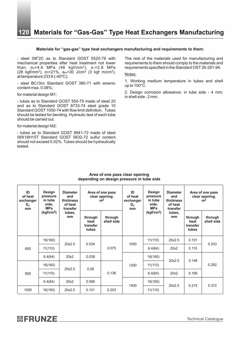
Technical Catalogue
- steel 09Г2С as to Standard GOST 5520-79 with mechanical properties after heat treatment not lower
2than: σв=4.6 МPа (46 kgf/mm ), σт=2.8 МPа 2 2 2(28 kgf/mm ), σ5=21%, акн=30 J/cm (3 kgf m/cm ),
at temperature 233 К (-40ºС);
- steel ВСт3пс Standard GOST 380-71 with arsenic content max. 0.08%;
for material design М1:
- tubes as to Standard GOST 550-75 made of steel 20 and as to Standard GOST 8733-74 steel grade 10 Standard GOST 1050-74 with flow limit definition. Tubes should be tested for bending. Hydraulic test of each tube should be carried out.
for material design М2:
- tubes as to Standard GOST 9941-72 made of steel 08Х18Н10Т Standard GOST 5632-72 sulfur content should not exceed 0.02%. Tubes should be hydraulically tested.
The rest of the materials used for manufacturing and requirements to them should comply to the materials and requirements specified in the Standard OST 26-291-94.
Notes:
1. Working medium temperature in tubes and shell up to 100°С.
2. Design corrosion allowance: in tube side - 4 mm; in shell side - 2 mm.
Materials for “gas-gas” type heat exchangers manufacturing and requirements to them:
Area of one pass clear opening,
2m
ID of heat
exchangerD , i
mm
Designpressure in tube side,MPa
2(kgf/cm )
Diameterand
thicknessof heattransfertubes,
mm throughheat
transfertubes
throughshell side
16(160) 11(110) 20x2.5 0.101
11(110) 20x2.5 0.034 1000
6 4(64) 20x2 0.115 0.203
600
6.4(64) 20x2 0.039
0.075
16(160)
16(160) 11(110) 20x2.5 0.146
11(110) 20x2.5 0,06
1200
6.4(64) 20x2 0.166
0.292
800
6.4(64) 20x2 0.068
0.136
16(160)
1000 16(160) 20x2.5 0.101 0.203 1400
11(110) 20х2.5 0.215 0.372
Area of one pass clear opening depending on design pressure in tube side
Materials for “Gas-Gas” Type Heat Exchangers Manufacturing120
Area of one pass clear opening,
2m
throughheat
transfertubes
throughshell side
.
ID of heat
exchangerD , i
mm
Designpressure in tube side,MPa
2(kgf/cm )
Diameterand
thicknessof heattransfertubes,
mm

Heat Exchagers
I I
Basic and connection dimensions (mm) of heat exchangers of type 1
Description S S1 L L1 L2 L3 Н H1 А В В1
1-600-16/8.8-6-М1 7930 4000
1-600-16/8.8-9-М1 40 20
10930 60001465 725 730 1820 450 125
1-600-11/6.4-6-М1 7770 4000
1-600-11/6.4-9-М1 26 16
10770 60001290 645 700 1760 450 120
1-600-6.4/6.4-6-М1 7710 4000
1-600-6.4/6.4-9-М1 20 16
10710 60001210 580 700 1695 450 100
180
1-800-16/8.8-6-М1 8440 4000
1-800-16/8.8-9-М1 55 25
11440 60001990 960 946 2360 500 170
1-800-11/6.4-6-М1 8100 4000
1-800-11/6.4-9-М1 36 20
11100 60001600 805 886 2240 500 150
1-800-6.4/6.4-6-М1 8045 4000
1-800-6.4/6.4-9-М1 26 20
11045 60001485 715 866 2030 500 100
1-1000-16/8.8-6-М1 8700 4000
1-1000-16/8.8-9-М1 65 32
11700 60002165 1045 1055 2580 650 195
1-1000-11/6.4-6-М1 8400 4000
1-1000-11/6.4-9-М1 45 25
11400 60001840 915 995 2450 650 185
250
1-1000-6.4/6.4-6-М1 32 25 3280 4000 1685 795 972 2240 650 125
1-1000-6.4/6.4-9-М1 11280 6000
1-1200-16/8.8-9-М1
80
36
12180 6000
2570
1250
1260
3100
800
230
1-1200-11/6.4-9-М1 50 28 11760 6000 2115 1045 1230 3040 800 205
1-1200-6.4/6.4-9-М1 40 28 11690 6000 1960 935 1170 2920 800 140
1-1400-16/8.8-9-М1 95 45 12400 6000 2665 1320 1375 3330 950 250
1-1400-11/6.4-9-М1 60 32 12085 6000 2350 1170 1340 3260 950 220
250
А
Д
Г
Е
Б В
L2S S
1
H
Free support
L1
L
L5
DВ
Layout of foundation bolt holes
Di = 600 mm Di = 800, 1000, 1200 mm Di = 1400 mm
80
В В1
А
80 140 140
ВВА А
55 140
I
Ж
Н1
80 28
R14
Heat Exchanger of Type 1121
В1 В1

Technical Catalogue
Heat exchanger of type 2 (layout of foundation bolt holes is similar to layout for heat exchanger of type 1)
Basic and connection dimensions (mm) of heat exchangers of type 2
Description S S1 L L1 L2 L3 Н H1 А В В1
2-600-16/8.8-6-М1 40 20 8655 4000 1465 725 730 1820 450 125
2-600-16/8.8-9-М1
11655 6000
2-600-11/6.4-6-М1 26 16 8495 4000 1290 645 700 1760 450 120
180
2-600-11/6.4-9-М1
11495 6000
2-600-6.4/6.4-6-М1 20 16 8440 4000 1210 580 700 1695 450 100
2-600-6.4/6.4-9-М1
11440 6000
2-800-16/8.8-6-М1 55 25 9165 4000 1990 960 946 2360 500 170 250
2-800-16/8.8-9-М1
12165 6000
2-800-11/6.4-6-М1 36 20 8825 4000 1600 805 886 2240 500 150
2-800-11/6.4-9-М1
11825 6000
2-800-6.4/6.4-6-М1 26 20 8775 4000 1485 715 866 2030 500 100
2-800-6.4/6.4-9-М1
11775 6000
2-1000-16/8.8-6-М1 65 32 9425 4000 2165 1045 1055 2580 650 195
2-1000-16/8.8-9-М1
12425 6000
2-1000-11/6.4-6-М1 45 25 9125 4000 1840 915 995 2450 650 185
2-1000-11/6.4-9-М1
12125 6000
2-1000-6.4/6.4-6-М1 32 25 9010 4000 1685 795 972 2240 650 125
2-1000-6.4/6.4-9-М1
12010 6000
2-1200-16/8.8-9-М1 80 36 12905 6000 2570 1250 1260 3100 800 230
2-1200-11/6.4-9-М1 50 28 12485 6000 2115 1045 1230 3040 800 205
2-1200-6.4/6.4-9-М1 40 28 12420 6000 1960 935 1170 2920 800 140
2-1400-16/8.8-9-М1 95 45 13125 6000 2665 1320 1375 3330 950 250
2-1400-11/6.4-9-М1 60 32 12810 6000 2350 1170 1340 3260 950 220
А
Д
Г
Е
Б В
L2
S S1
H
Free support
L1
L
L5
DB
Ж
Н1
Heat Exchanger of Type 2122
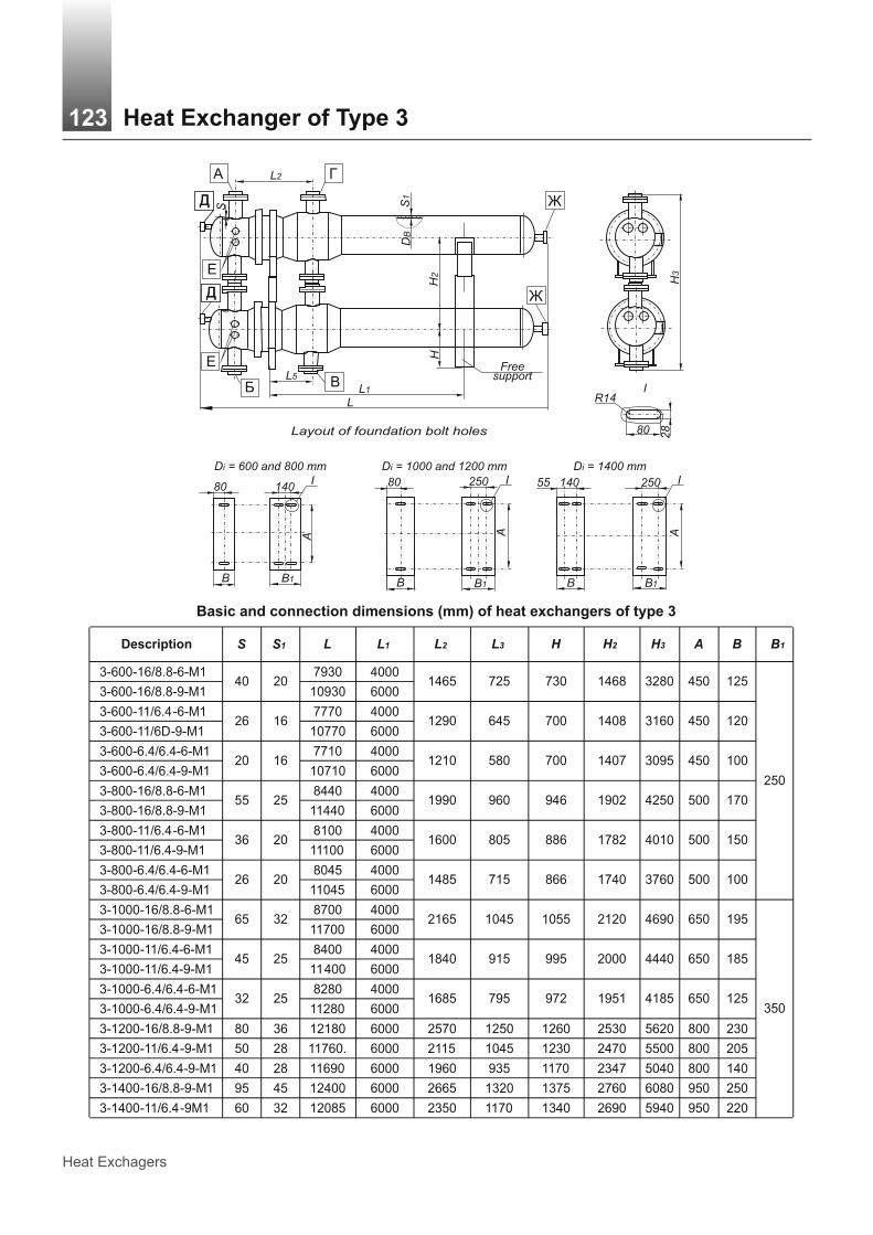
Heat Exchagers
I I
Basic and connection dimensions (mm) of heat exchangers of type 3
3-600-16/8.8-6-М1 7930 4000
3-600-16/8.8-9-М1 40 20
10930 6000 1465 725 730 1468 3280 450 125
3-600-11/6.4-6-М1 7770 4000
3-600-11/6D-9-М1 26 16
10770 6000 1290 645 700 1408 3160 450 120
3-600-6.4/6.4-6-М1 7710 4000
3-600-6.4/6.4-9-М1 20 16
10710 6000 1210 580 700 1407 3095 450 100
3-800-16/8.8-6-М1 8440 4000
3-800-16/8.8-9-М1 55 25
11440 6000 1990 960 946 1902 4250 500 170
3-800-11/6.4-6-М1 8100 4000
3-800-11/6.4-9-М1 36 20
11100 6000 1600 805 886 1782 4010 500 150
3-800-6.4/6.4-6-М1 8045 4000
3-800-6.4/6.4-9-М1 26 20
11045 6000 1485 715 866 1740 3760 500 100
250
3-1000-16/8.8-6-М1 8700 4000
3-1000-16/8.8-9-М1 65 32
11700 6000 2165 1045 1055 2120 4690 650 195
3-1000-11/6.4-6-М1 8400 4000
3-1000-11/6.4-9-М1 45 25
11400 6000 1840 915 995 2000 4440 650 185
3-1000-6.4/6.4-6-М1 8280 4000
3-1000-6.4/6.4-9-М1 32 25
11280 6000 1685 795 972 1951 4185 650 125
3-1200-16/8.8-9-М1 80 36 12180 6000 2570 1250 1260 2530 5620 800 230
3-1200-11/6.4-9-М1 50 28 11760. 6000 2115 1045 1230 2470 5500 800 205
3-1200-6.4/6.4-9-М1 40 28 11690 6000 1960 935 1170 2347 5040 800 140
3-1400-16/8.8-9-М1 95 45 12400 6000 2665 1320 1375 2760 6080 950 250
3-1400-11/6.4-9М1 60 32 12085 6000 2350 1170 1340 2690 5940 950 220
350
Layout of foundation bolt holes
Di = 600 and 800 mm Di = 1000 and 1200 mm Di = 1400 mm
80
В В1
А
80 250 140
ВВ
А А
55 250140I
I
80 28
R14
Е
Б В
H
Free support
L1
L
L5
Н3
А
Д
Г
Е
L2
S S1
DB
Ж
H2
Д Ж
Д
Д
Heat Exchanger of Type 3123
В1 В1
H2Description S S1 L L1 L2 L3 Н Н3 А В В1

Technical Catalogue
Д
Д
Heat exchanger of type 4 (layout of foundation bolt holes is similar to layout for heat exchanger of type 3)
Basic and connection dimensions (mm) of heat exchangers of type 4
H2Description S S1 L L1 L2 L3 Н Н3 А В В1
4-600-16/8.8-6-М1 8655 4000
4-600-16/8.8-9-М140 20
11655 60001465 725 730 1468 3280 450 125
4-600-11/6.4-6-М1 8495 4000
4-600-11/6.4-9-М126 16
11495 60001290 645 700 1408 3160 450 120
4-600-6.4/6.4-6-М1 8440 4000
4-600-6.4/6.4-9-М120 16
11440 60001210 580 700 1407 3095 450 100
4-800-16/8.8-6-М1 9165 4000
4-800-16/8.8-9-М155 25
12165 60001990 960 946 1902 4250 500 170
4-800-11/6.4-6-М1 8825 4000
4-800-11/6.4-9-М136 20
11825 60001600 805 886 1782 4010 500 150
4-800-6.4/6.4-6-М1 8775 4000
4-800-6.4/6.4-9-М126 20
11775 60001485 715 866 1740 3760 500 100
250
4-1000-16/8 8-6-М1 9425 4000
4-1000-16/8.8-9-М165 32
12425 60002165 1045 1055 2120 4690 650 195
4-1000-11/6.4-6-М1 9125 4000
4-1000-11/6.4-9-М145 25
12125 60001840 915 995 2000 4440 650 185
4-1000-6.4/6.4-6-М1 9010 4000
4-1000-6.4/6.4-9-М132 25
12010 60001685 795 972 1951 4185 650 125
4-1200-16/8.8-9-М1 80 36 12905 6000 2570 1250 1260 2530 5620 800 230
4-1200-11/6.4-9-М1 50 28 11485 6000 2115 1045 1230 2470 5500 800 205
4-1200-6.4/6.4-9-М1 40 28 12420 6000 1960 935 1170 2347 5040 800 140
4-1400-16/8.8-9-М1 95 45 13125 6000 2665 1320 1375 2760 6080 950 250
4-1400-11/6.4-9М1 60 32 12810 6000 2350 1170 1340 2690 5940 950 220
350
Е
Б В
H
Free support
L1
L
L5
Н3
А Г
Е
L2
S S1
DB
Ж
H2
Ж
Heat Exchanger of Type 4124
.

Heat Exchagers
* For heat exchangers of types 2 and 4: nozzle Д - for glycol injection (2 pc. — for single-stage heat exchangers, 4 pc. - for double-stage); nozzle Е - for pressure drop measuring (2 pc. - for single-stage heat exchangers, 4 pc. - for double-stage).** For single-stage heat exchangers - 1 pc.; for double-stage - 2 pc.
Table of Nozzles125
10(100)
6.3(63)
10(100)
6.3(63)
10(100)
6.3(63)
10(100)
6.3(63)
10(100)
6.3(63)
600-16/8.8-6 600-16/8.8-9600-11/6.4-6 600-11/6.4-9600-6.4/6.4-6 600-6.4/6.4-9800-16/8.8-6 800-16/8.8-9800-11/6.4-6 800-11/6.4-9800-6.4/6.4-6 800-6.4/6.4-91000-16/8.8-6 1000-16/8.8-91000-11/6.4-6 1000-11/6.4-91000-6.4/6.4-6 1000-6.4/6.4-9
1200-16/8.8-9
1200-11/6.4-9
1200-6.4/6.4-9
1400-16/8.8-9
1400-11/6.4-9
А(inlet
of wet gas)
Б(outlet
of wet gas)
В(inlet of
dried gas)
Г(outlet of
dried gas)
Д*(stand-by)
Е*(stand-by)
Ж**(mounting)
2Nominal pass (diameter) (mm) and nominal pressure МPа (kgf/cm )
Heat exchangerdescription
DN PN DN PN DN PN DN PN DN PN DN PN DN PN
200
300
400
200
300
400
200
300
400
200
300
400
5016
(160)25
16(160)
80
16(160)
6.3(63)
16(160)
6.3(63
16(160)
6.3(63)
6(160)
6.3(63)
16(160)
)
1
16(160)
6.3(63)
16(160)
6.3(63
16(160)
6.3(63)
6(160)
6.3(63)
16(160)
)
1
10(100)
6.3(63)
10(100)
6.3(63)
10(100)
6.3(63)
10(100)
6.3(63)
10(100)
6.3(63)
10(100)
6.3(63)
10(100)
6.3(63)
10(100)
6.3(63)
10(100)
6.3(63)
10(100)
6.3(63)

Technical Catalogue
Vaporizersand Tube Bundles to Them

Heat Exchagers
Vaporizers are designed for processing media evaporation during the processes carried out in oil, chemical, petrochemical, gas and other industries and manufactured for domestic and overseas supply.
The units can be operated in micro climatic areas with temperate and tropical climate. Climatic design “U” and “T”, product category 1 as to Standard GOST 15150.
The units are designed for installation in geographical regions of seismicity up to 7 points according to 12-points scale adopted in Ukraine.
Technical requirements to materials, manufacture, acceptance, testing methods and preservation of apparatuses per SOU МPP 71.120-217:2009, GOST R 52630 and Technical Regulation of Customs Union 032/2013.
The example of description of heat exchanger when ordering:
Vaporizer with vapor space, floating head (IP), shell of 1800 mm diameter, 1.6 МPа nominal pressure in shell, 2.5 МPа in tubes, material design М1, with heat transferring tubes of 25 mm diameter, 6 m length, 4-passes through tube-side, climatic design (U), with fitting components for thermal insulation:
Vaporizer with vapor space 1800IP-1.6-2.5-М1/25-6-4-U-I Specification ТU 3612-013-00220302-99.
Vaporizer with vapor space, U-shape tubes (IU), shell of 1200 mm diameter, 2.5 МPа nominal pressure in shell, 2.5 МPа in tubes, material design М4, with heat transferring tubes of 20 mm diameter, 6 m length, 2-passes through tube-side, climatic design (T), without fitting components for thermal insulation:
Vaporizer with vapor space 1200IU-2.5-2.5-М4/20-6-2-Т Specification ТU 3612-013-00220302-99.
When ordering vaporizers the questionnaire in the form given bellow should be submitted.
At the Customer’s request the following is allowed:
1. Install additional DN 80 mm nozzles, but max. 0.1 D, where D - vaporizer diameter;
2. Take reduced diameter of one or more nozzles (nozzle diameter increasing is not allowed);
3. The equipment and nozzles flanges facing to be tongue-and-groove;
4. Take the layout of supports in relation to nozzles different from layout between supports;
5. Fulfil fastening of tubes in tube sheets with flaring seal welding (in the absence of specific indication, the manufacturer chooses the type of tube connection to the tube sheets).
6. Do not install fitting components for thermal insulation.
Orders of vaporizers with above mentioned design changes should be carried out in the form given bellow.
Notes: It is allowed to manufacture vaporizers and tube bundles for specific design conditions, listed in the questionnaire or order form without sacrificing basic dimensions and material design as to description of the vaporizer to be ordered. In this case the weight of vaporizers is determined on the base of design pressure and temperature.
The example of tube bundle for heat exchanger when ordering:
Tube bundle (PT) for the vaporizer with vapor space, floating head (IP), shell of 1800 mm diameter, 1.6 МPа (the highest pressure in tubes and shell is specified), material design М1, with heat transferring tubes of 25 mm diameter, 6 m length, 4-passes through tube-side:
Tube bundle PT 1800IP-1.6-М1/25-6-4 Specification TU 3612-013-00220302-99.
Tube bundle (PT) for vaporizer with vapor space, U-shape tubes (IU), shell of 1200 mm diameter, 2.5 МPа nominal pressure, material design М4, with heat transferring tubes of 20 mm diameter, 6 m length, 2-passes through tube-side:
Tube bundle PТ 1200IU-2.5-М4/20-6-2 Specification ТU 3612-013-00220302-99.
When ordering tube bundles for heat exchangers the questionnaire in the form given bellow should be submitted.
Vaporizers and Tube Bundles to Them127

Technical Catalogue
For tube bundle installation
For level indicator
Outlet of product rest
Drainage
Inlet of liquid product
Outlet of vapor or liquid
Inlet of vapor or liquid
For pressure gauge
Outlet of product vapor
For safety valve
Manhole
For level indicator
I
II
III
IV
V
VI
VII
VIII
IX
X
XI
XII
DN 200
DN 40
DN4
DN 50
DN3
DN2
DN 15
DN1
DN 80
DN 500
DN 50
DN2
Nozzles Table
2300±3
1500±3
700±3
22
0
13
0
DB
А
h2
h3
20
0
h1
150
l0* l
l1
l2
l4
~L
IV
4000±3
180
110
180
h
l5*
H/2
H
VII
VIII
IX X X
II
XII
II
IIIV VI
6000-10 - length of straight part of tubes
1200
IU Type Vaporizer 128
l3
Vaporizer of IU type

Heat Exchagers
For tube bundle installation
For level indicator
Outlet of product rest
Drainage
Inlet of liquid product
Outlet of vapor or liquid
Inlet of vapor or liquid
For pressure gauge
Outlet of product vapor
For safety valve
Manhole
For level indicator
I
II
III
IV
V
VI
VII
VIII
IX
X
XI
XII
DN 200
DN 40
DN4
DN 50
DN3
DN2
DN 15
DN1
DN 80
DN 500
DN 50
DN2
Nozzles Table
Vaporizer of IP type
XII
II
II
150
700±3
22
0
l
1500±3
А
2300±3
III 180
X
13
0
X
IV
4000±3
IX
110
20
0
VIII
h
180 V VI
VII
H/2
H
1200
IP Type Vaporizer 129
DB
h2
h3
h1
l0*
l1
l2
l4
~L
l5*
l3
6000-10 - length of straight part of tubes

Technical Catalogue
Free support Fixed support
Maximum design pressure, МPа, at medium temperature, °С Nominal pressure PN,МPа до 100 200 250 300 350 400 425 450
1.0 1.00 0.93 0.90 0.75 0.66 0.58 0.50 0.36
1.6 1.60 1.49 1.40 1.20 1.10 0.90 0.80 0.57
2.5 2.50 2.32 2.25 1.90 1.70 1.50 1.30 0.90
4.0 4.00 3.72 3.50 3.00 2.60 2.30 2.00 1.40
Maximum design pressure of heat exchangers depending on medium temperature
I
A2
A3
A2
A3
A AA1 A
1
4 holes Ø36
36 80
R18
Layout of vaporizers support foundation bolts holes
Layout of Support Foundation Bolts Holes130
Shell inner diameter, Di
800
1000
1200
1400
1600
1800
2000
А
500
650
800
950
1100
1500
140
200
A2
250
300
A3
740
1000
1100
1250
1420
1600
1770
A1
Dimensions, mm

Heat Exchagers
Basic parameters of vaporizers with vapor space
Basic Parameters of Vaporizers with Vapor Space131
1.6 / 1.6
Parameters value for vaporizersParameters
IP IU
Heat transferring surface, m2 38-357 80-585
Shell inner diameter, mm(of sheet metal)
800;1000;1200;1400;1600;1800;2000
Temperature of heating andevaporable media, (T5),°C
from -30 up to +450
Nominal pressure, МPа,max. in shell/tubesfor units with diameter, mm:
8001.6 / 1.62.5 / 4.0
1.6 / 1.62.5 / 4.0
1000-18001.6 / 2.5
-1.6 / 2.52.5 / 2.5
20001.0 / 1.61.6 / 1.6
-
1.0 / 1.6
2.5 / 1.6
Length of heat transferring tubes, mm 6000
Outer diameter and wall thicknessof heat transferring tubes, mm
25х2; 25x2.5 20х2
Number of passes through the tubesfor units with diameter, mm
800-1600 2
1800-2000 2; 4
2
Layout of heat transferring tubesin tube sheets and partition walls
Layout - on square tops

Technical Catalogue
1800
- - - - - - -
2.5
1.6
1.6
1.6
1.6
1.6
1.6
1.0
1.6
800
500
1000
600
1200
700
***
1400
800
1600
900
1000
1100
2000
1200
2.5
1.6
4.0
2.5
4.0
2.5
1.6
2.5
2.5
2.5
1.6
2.5
2.5
2.5
1.6
2.5
2.5
1.6
2.5
2.5
2.5
1.6
2.5
2.5
2.5
1
.6
2.5
2.5
1.0
1.6
1.6
2.5
1.6
884
442
616
565
984
492
716
665
1088
544
816
765
1188
594
920
865
1332
666
1020
965
1392
696
1492
746
1124
1170
1228
1694
847
1238
1300
24
53
70
32
5
35
5
67
0
8040
8220
8280
-
8530
-
9020
-
9200
-
9490
-
9540
-
9830
-
7900
7990
811
0
8350
8820
9000
9280
9300
9610
9700
460
525
575
630
705
35
0
760
790
40
0
1200
1450
12
00
17
50
10
00
15
50
1200
17
50
1060
16
10
6390
6400
6280
6400
6300
6350
6370
6560
7120
7210
7205
7335
7690
7735
7950
7940
8210
8260
460
550
550 -
620 -
700 -
760 -
780 -
840 -
830 -
320
380
440
500
560
570
600
610
650
150
250
150
200
300
200
20
01
00
250
350
300
400
250
350
300
400
350
15
0
400
500
250
25
0
20
0
Vaporizers and Tube Bundles to Them132
Inner diameter of distributing chamber,D1, mm
Shell inner diameter, Di, mmP
res
uu
re P
N,
МP
а
Fo
r ty
pe
IPIU
Н±6
Н/2±3
In shell
In tubes
In shell
In tubes
~
1
L
Fo
r ty
pe
Fo
r ty
pe
h±3
h
h2
h3
IPIU
IPIU
АD
N1
l±3
l0*
l1±3
l2±3
l3±3
l4±3
l5*
DN
2D
N3
DN
4
Dim
ensi
ons,
mm

Heat Exchagers
Heat
tran
sfe
rrin
g s
urf
ace a
s t
o t
ub
es o
ute
r d
iam
ete
r an
d c
lear
op
en
ing
are
a o
f IP
an
d I
U t
yp
es v
ap
ori
zers
Note
: H
eat
transf
err
ing s
urf
ace
is g
iven w
ithout tu
be s
heets
thic
kness
.
Heat Transferring Surface of IP and IU Types Vaporizers133
20
- 104
-8
0-
-0
.02
1800
500
25
82
-38
-0
.01
40
.01
3-
20
- 155
-1
20
--
0.0
31
1000
600
25
132
-62
-0
.02
30
.02
1-
20
- 226
-1
76
--
0.0
45
1200
700
25
210
-98
-0
.03
60
.03
3-
20
- 295
-2
31
--
0.0
59
1400
800
25
280
-131
-0
.04
80
.04
4-
20
- 389
-3
06
--
0.0
78
1600
900
25
378
-
2
178
-0
.06
50
.05
9-
20
- 490
-3
87
--
0.0
98
1000
25
490
-2
230
-0
.08
40
.07
7-
20
- -
--
--
-1000
25
456
-4
214
-0
.03
60
.03
3-
20
- 605
-4
81
--
0.1
21
1100
25
632
-2
297
-0
.10
90
.09
9-
20
- -
--
--
-
1800
1100
25
596
-4
281
-0
.04
70
.04
3-
20
- 733
-5
86
--
0.1
47
1200
25
758
-2
357
-0
.13
10
.11
9-
20
- -
--
--
-2000
1200
25
716
-4
337
-0
.05
60
.05
1-
2.0
Qu
an
tity
of
heat
tran
sfe
rrin
g t
ub
es
Heat
tran
sfe
rrin
g2
su
rfa
ce
, m
Cle
ar
op
en
ing
are
a o
f 2
on
e p
as
s t
hro
ug
h t
he
tu
be
s, m
for
typ
efo
r ty
pe
IPIU
at
tub
e w
all t
hc
kn
es
s, m
m
Inn
er
dia
mete
ro
f sh
ell, D
i,m
m
Inn
er
dia
mete
ro
f d
istr
ibu
tin
gch
am
ber,
D1,
mm
Ou
ter
dia
mete
ro
f tu
bes,
mm
IPIU
Qu
an
tity
o
f p
asses
thro
ug
hth
e t
ub
es
IPIU
2.5
2.0

Technical Catalogue
Inn
er
dia
me
ter
of
sh
ell
, D
i,m
m
80
0
10
00
12
00
14
00
16
00
18
00
20
00
Inn
er
dia
me
ter
of
dis
trib
uti
ng
ch
am
be
r, D
1,
mm
50
0
60
0
70
0
80
0
90
0
10
00
10
00
110
0
110
0
12
00
12
00
Pre
ss
ure
in s
he
ll P
N,
MP
a
1.6
2.5
1.6
2.5
1.6
2.5
1.6
2.5
1.6
2.5
1.6
2.5
1.6
2.5
1.6
2.5
1.6
2.5
1.0
1.6
2.5
1.0
1.6
2.5
Pre
ss
ure
in
tu
be
s,
MP
a
1.6
4.0
2.5
2.5
2.5
2.5
2.5
2.5
2.5
2.5
1.6
1.6
Qu
an
tity
of
pa
ss
es
thro
ug
h
the
tu
be
s
2 4 2 4 2 4
We
igh
t o
f v
ap
ori
zers
, k
g
Fo
r IP
ty
pe
12
95
0
tub
es
25
х2
.0
ste
el g
rad
es
08
Х1
8Н
10
Т,
12
Х1
8Н
10
Т,
10
Х1
7Н
13
М2
Т,
08
Х1
3
30
20
36
00
44
00
-6
15
0-
84
40
-9
26
0- -
12
92
0-
14
01
0-
13
97
0-
15
83
01
67
80
-1
57
90
16
74
0-
98
90
tub
es
25
х2
.5
ste
el g
rad
e
10
,20
, 1
5Х
5М
, Х
8
31
20
37
00
46
00
-6
42
0-
88
90
- -1
37
30
-1
36
90
-1
50
45
-1
50
00
-1
73
00
18
30
0-
17
24
51
82
45
-
Fo
r IU
ty
pe
tub
es
20
х2
.0
ste
el g
rad
e 1
0,
20
, 0
8Х
18
Н1
0Т,
12
Х1
8Н
10
Т,
10
Х1
7Н
13
М2
Т
36
60
40
40
50
00
50
50
67
50
72
60
92
90
99
80
10
43
01
21
50
14
21
01
57
30
- -1
52
00
16
09
0- -
17
51
01
84
80
20
10
0- - -
Weig
ht
of
IP a
nd
IU
typ
es V
ap
ori
zers
Note
s:3
1.
Weig
ht of va
porize
rs is
calc
ula
ted for
steel w
ith v
olu
me w
eig
ht 7.8
5 g
/cm
.2.
Weig
ht of va
porize
rs is
calc
ula
ted for
sheet m
eta
l nom
inal t
hic
kness
with
out ta
king a
count th
e d
evi
ce f
or
dis
trib
utin
g c
ham
bers
cove
rs h
angin
g.
Weight of IP and IU Types Vaporizers134

Heat Exchagers
Materials for Vaporizers Manufacturing135M
ate
rials
, ap
plied
fo
r m
an
ufa
ctu
re o
f assem
bly
un
its o
f m
ain
co
mp
on
en
ts a
nd
part
s o
f vap
ori
zers
an
d t
ub
e b
un
dle
s
Ma
teri
al
Ty
pe
of
va
po
rize
r
Ma
teri
al
de
sig
n o
fv
ap
ori
zer
Ap
pli
ca
tio
nte
mp
era
ture
ran
ge
, °C
Sh
ell
Dis
trib
uti
ng
ch
am
be
rTu
be
sTu
be
sh
ee
tS
he
ll g
as
ke
tsD
istr
ibu
tin
gc
ha
mb
er
ga
sk
ets
М1
Ste
el g
rades
10 a
nd
20 a
s to
Sta
ndard
GO
ST
1050,
GO
ST
550, gr. A
, G
OS
T 8
733 g
r. B
Ste
el 0
9Г2С
as
toS
tandard
GO
ST
5520
or
GO
ST
8479 g
r. IV
GO
ST
19281
Spiral-w
ound g
ask
ets
SN
P S
peci
ficatio
ns
TU
U 2
006 3
327.0
02
-200
Gask
ets
of th
e c
om
pany
Fre
nze
lit (
Nova
tec
Pre
miu
m; N
ova
phit
VS
, S
ST
S, E
XT
RA
,S
UP
ER
HP
S)
IP -
IU
fro
m -
30
to
+4
50
Ste
el С
т3сп
as
toS
tandard
GO
ST
380,
GO
ST
14637.
Ste
el 0
9Г2С
as
toS
tandard
G
OS
T 5
520
Ste
el С
т3сп
as
toS
tandard
G
OS
T 3
80,
GO
ST
14637.
Ste
el 0
9Г2С
as
toS
tandard
GO
ST
5520
Tubes
- st
eel 2
0as
to S
tandard
GO
ST
8731
М1
2
Ste
el 0
9Г2С
as
to
Sta
ndard
GO
ST
5520
or
GO
ST
8479 g
r. IV
GO
ST
19281
with
sta
inle
ss s
teel
weld
faci
ng
IU
М1
3S
heet asb
est
os
as
to G
OS
T 2
850
In s
hell
of
М-Н
Т-0
8Х
18
Н10
Т s
teel
as
to G
OS
T 4
986
fro
m -
30
to +
35
0
Ste
el С
т3сп
as
to S
tandard
GO
ST
380,
GO
ST
14637.
Ste
el 0
9Г2С
as
toS
tandard
GO
ST
5520
Ste
el С
т3сп
as
to S
tandard
GO
ST
380,
GO
ST
14637.
Ste
el 0
9Г2С
as
toS
tandard
GO
ST
5520
Ste
el 0
8X
18H
10T
or
12X
18H
10T
as
to S
tandard
G
OS
T 5
632,
GO
ST
9941
Ste
el 0
8X
22H
6T
or
12X
18H
10T
as
to S
tandard
G
OS
T 5
632,
GO
ST
9941
Ste
el 1
2Х
18Н
10Т
as
toS
tandard
GO
ST
7350
gr. M
2б
, G
OS
T 2
5054
gr. IV
and T
ech
nic
al
Docu
ments
appro
ved
in a
ccord
ance
with
est
ablis
hed p
roce
dure
IPМ
13
fro
m -
30
to +
35
0
Ste
el С
т3сп
as
to S
tandard
GO
ST
380,
GO
ST
14637.
Ste
el 0
9Г2С
as
toS
tandard
GO
ST
5520
Ste
el 0
8X
18H
10T
or
12X
18H
10T
as
to S
tandard
G
OS
T 5
632,
GO
ST
9941
Ste
el 1
2Х
18Н
10Т
as
toS
tandard
GO
ST
7350
gr. M
2б
, G
OS
T 2
5054
gr. IV
and T
ech
nic
al
Docu
ments
appro
ved
in a
ccord
ance
with
est
ablis
hed p
roce
dure
Spiral-w
ound g
ask
ets
SN
P S
peci
ficatio
ns
TU
U 2
006 3
327.0
02
-200
Gask
ets
of th
e c
om
pany
Fre
nze
lit (
Nova
tec
Pre
miu
m; N
ova
phit
VS
, S
ST
S, E
XT
RA
,S
UP
ER
HP
S)
Spiral-w
ound g
ask
ets
SN
P S
peci
ficatio
ns
TU
U 2
006 3
327.0
02
-200
Gask
ets
of th
e c
om
pany
Fre
nze
lit (
Nova
tec
Pre
miu
m; N
ova
phit
VS
, S
ST
S, E
XT
RA
,S
UP
ER
HP
S)
М4
Ste
el 1
5X
5M
or
as
to S
tandard
GO
ST
550-7
5 g
r. A
Ste
el 1
5Х
5М
* as
toS
tandard
GO
ST
7350
gr. M
2б
, G
OS
T 8
479
gr. IV
and T
ech
nic
al
Docu
ments
appro
ved
in a
ccord
ance
with
est
ablis
hed p
roce
dure
Spiral-w
ound g
ask
ets
SN
P S
peci
ficatio
ns
TU
U 2
006 3
327.0
02
-200
Gask
ets
of th
e c
om
pany
Fre
nze
lit (
Nova
tec
Pre
miu
m; N
ova
phit
VS
,S
ST
S, E
XT
RA
,S
UP
ER
HP
S)
Spiral-w
ound
gask
ets
SN
PS
peci
ficatio
ns
TU
U2006 3
327.0
02
-200
Gask
ets
of th
e
com
pany
Fre
nze
lit(N
ova
tec
Pre
miu
m;
Nova
phit
VS
,S
ST
S, E
XT
RA
,S
UP
ER
HP
S)

Technical Catalogue
1 - partition wall; 2 - heat transferring tube; 3 - baffle plate; 4 - tube sheet.
Note: х*- baffle plate location is specified at the site
8 - 10
10 -
14
D4 66
S
A Б
r
r
r
r
12
r ≤12mm
6000 - length of straight part of tubes
1100 1200 х 4 = 4800 1200
S1A
Б
43х*
6
D3
21
a
Two-Passes Tube Bundles for Vaporizers of IU Type136
D1
D4

Heat Exchagers
Four-passes tube bundles for vaporizers of IP type
1 - flexible sheet; 2 - partition wall; 3 - tube heat transferring; 4 - baffle plate; 5 - tube sheet.
1
S
2
6000 - tube length
1200
3х*
6
4
a
S
5
1
S
2
6000 - tube length
1200
3х*
6
4
a
S
5
Two-Passes Tube Bundles for Vaporizers of IP Type137
S1
D3
D1
D2
S1
D3
D1
D2

Technical Catalogue
Basic
dim
en
sio
ns o
f tu
be b
un
dle
s f
or
vap
ori
zers
of
IP a
nd
IU
typ
es
10
5
80
0
10
00
12
00
14
00
16
00
18
00
20
00
50
0*
60
0*
70
0*
80
0
90
0
10
00
110
0
12
00
4.0
2.5
1.6
2.5
1.6
1.6
1.6
1.6
1.6
1.6
1.0
1.6
4.0
2.5
2.5
2.5
2.5
2.5
2.5
1.6
- - - - - - -
2.5
1.6
2.5
1.6
2.5
1.6
2.5
1.6
2.5
1.6
2.5
1.6
2.5
1.0
1.6
2.5
1.6
25
0
49
74
96
37
2
59
75
96
47
0
69
66
95
56
8
79
67
95
66
0
89
58
95
76
0
99
59
95
86
2
10
95
10
95
96
2
56
3
55
7
66
3
77
3
87
5
97
7
10
78
118
8
12
66
12
94
39
6
49
6
59
2
69
0
79
0
89
0
99
0
10
90
119
511
95
10
60
30
0
40
50
50
70
45 -
65
10
55 -
75
60 -
85
65 -
90
70 -
10
0
75 - 75
95
-11
5
12
* It is
allo
wed to m
ake
dis
trib
utin
g c
ham
ber
of tu
bes
of 530, 630, 720 m
m d
iam
ete
r.
Basic Dimensions of Tube Bundles for Vaporizersof IP and IU Types138
S
for
typ
e
Pre
ss
ure
PN
, М
Pа
for
typ
e
IPIU
Inn
er
dia
me
ter
of
sh
ell
,D
i, m
m
Inn
er
dia
me
ter
of
dis
trib
uti
ng
ch
am
be
r D
1,
mm
in s
he
llin
tu
be
s
in s
he
ll
in t
ub
es
D1
а
IPIU
S1
D2
D3
D4
D5
Dim
ensi
ons,
mm

Heat Exchagers
Weig
ht
of
tub
e b
un
dle
s f
or
vap
ori
zers
of
IP
an
d I
U
800
1000
1200
1400
1600
1800
2000
500
600
700
800
900
1000
1000
1100
1100
1200
1200
1.6
2.5
1.6
2.5
1.6
2.5
1.6
2.5
1.6
2.5
1.6
2.5
1.6
2.5
1.6
2.5
1.6
2.5
1.0
1.6
2.5
1.0
1.6
1.6
4.0
2.5
2.5
2.5
2.5
2.5
2.5
2.5
2.5
1.6
1.6
2 4 2 4 2 4
780
800
1180
1820
2530
3260
4220
4020
5410
5200
6420
6170
91
09
30
13
90
21
60
29
80
38
60
50
00
47
40
64
10
61
40
76
20
73
00
13
50
13
80
19
80
29
40
38
30
50
10
63
20
-
78
40
-
93
60
95
50
-
Note
s:
31.
Weig
ht of tu
be b
undle
s is
calc
ula
ted for
steel w
ith v
olu
me w
eig
ht 7.8
5 g
/cm
.2.
Weig
ht of tu
be b
undle
s is
calc
ula
ted for
sheet m
eta
l nom
inal t
hic
kness
with
out ta
king a
cou
nt
the d
evi
ce f
or
dis
trib
utin
g c
ham
bers
co
vers
hangin
g.
Weight of Tube Bundles for Vaporizers of IP and IU Types139W
eig
ht
of
tub
e b
un
dle
s, k
g
Fo
r IP
ty
pe
Fo
r IU
ty
pe
Inn
er
dia
mete
ro
f sh
ell, D
i,m
m
Inn
er
dia
mete
ro
f d
istr
ibu
tin
gch
am
ber,
D1,
mm
Pre
ssu
rein
sh
ell
, P
N,
MP
a
Pre
ssu
re
in t
ub
es
Qu
an
tity
of
passes
thro
ug
h t
ub
es
Ste
el
08Х
18Н
10
Т,
12Х
18Н
10
ТS
tee
l 1
0, 2
0S
tee
l 1
0, 2
0,
08
Х1
8Н
10
Т,
12
Х1
8Н
10
Т
tub
es
25
х2
.0
tub
es
25
х2
.5tu
be
s 2
0х
2.0

Technical Catalogue
Questionnaire for order of heat exchanger as to Specification ТУ 3612-013-00220302-99
Vaporizer Designation1.
2.
2.1
2.2
2.3
2.4
2.5
2.6
2.7
2.8
3.
4.
5.
6.
In tubes In shell
inletoutlet
- flammability as to standard GOST 12.1.004 “yes”, “no”
- explosive hazard as to standard GOST 12.1.011 (indicating mixture category and group)
Design and operating conditions Medium parameter
Pressure, МPа Рworking
Рdesign
Working temperature, °С
Design temperature, °С
Minimum allowed (negative) temperatureof vaporizer wall under pressure, °С
Average air temperatureof the coldest five days at heat exchanger layout (site),°С,(fill for vaporizers to be installed outdoors or in unheated rooms)
Working medium designation and percentage composition
Physical state of medium (gas, vapor, liquid)
Medium characteristics: harmfulness as to standard GOST 12.1.007(indicating the hazard class)
Necessity of installation of parts for thermal insulation fixing "yes", "no"(delete as applicable)
Necessaty of ICC testing of base metal and welded joints“yes”, “no”, if “yes” specify procedure as to standard GOST 6032___________(fill for heat exchangers where steel grade 08Х18Н10Т, 12Х18Н10Т, 10Х17Н13М2Т is applied)
Specify: pivot points "left", "right", "not required" (delete as applicable) (fill only for vaporizers with distributing chamber diameter 600 -1200 mm)
Horizontal heat exchangers are installed: "on concrete foundation", "on metal structures"(delete as applicable)
Questionnaire for Order of Heat Exchangeras to Specification ТУ 3612-013-00220302-99140
Questionnaire is not subject to be agreed
Name of the Company-User and process plant or line__________________________________________________________________________________________________________________________________________________________________________________________________________Name and postal address of the Company that filled Questionnaire_____________________________________________________________________________________________________________________________________________________Signature of the head of the Company that filled Questionnaire________________________________________________________________________________________________________________________________________________________
___________________ _________________ _______________________ (title) (date) (signature)

Heat Exchagers
Questionnaire is not subject to be agreed
Name of the Company-User and process plant or line__________________________________________________________________________________________________________________________________________________________________________________________________________Name and postal address of the Company that filled Questionnaire_____________________________________________________________________________________________________________________________________________________Signature of the head of the Company that filled Questionnaire________________________________________________________________________________________________________________________________________________________
___________________ _________________ _______________________ (title) (date) (signature)
Order form of heat exchanger as to Specifications ТУ 3612-013-00220302-99with design changes, required by these Specifications
1.
2.
2.1.
2.2.
2.3.
2.4.
2.5.
2.6.
2.7.
2.8.
3.
4.
5.
6.
7.
8.
9.
10.
11.
Р design
in tubes in shell
inlet outlet
Standard heat exchanger designation
Design and operating conditions Medium parameter
Pressure, МPа Рworking
Working temperature, °С
Design temperature, °С
Minimum allowed (negative) temperatureof heat exchanger wall under pressure, °С
Average air temperature of the coldest five days at heat exchanger layout (site),°С,(fill for heat exchangers to be installed outdoors or in unheated rooms)
Working medium designation and percentage composition
Physical state of medium (gas, vapor, liquid)
Medium characteristics: - harmfulness as to standard GOST 12.1.007 (indicating the hazard class) - flammability as to standard GOST 12.1.004 "yes", "no" - explosive hazard as to standard GOST 12.1.011 (indicating mixture category and group)
Necessity of installation of parts for thermal insulation fixing "yes", "no"(delete as applicable)
Necessaty of ICC testing of base metal and welded joints“yes”, “no”, if “yes” specify procedure as to standard GOST 6032___________ (fill for heat exchangers where steel grade 08Х18Н10Т, 12Х18Н10Т, 10Х17Н13М2Т is applied)
Specify: pivot points "left", "right", "not required" (delete as applicable)(fill only for vaporizers with distributing chamber diameter 600 -1200 mm)
Specify type of tube fastening in sheets: "expanding", «seal welding with expanding" (delete as applicable)
Heat exchangers are installed: «on concrete foundation", "on metal structures"(delete as applicable)
Nozzles
Index Nominal bore
Designationof flange connection
Notes:1. Nominal bores are specified when they are smallerthan those that specified in these Specifications.
2.When flange connection designation is not specified,counter flange is installed on nozzles
The content of adopted differences from heat exchanger prototype as to Specifications TU 3612-013-00220302-99
Adopted differences reason
Order Form for heat exchanger manufacturing as to Specification ТU 3612-013-00220302-99 with design changesis not subject to be agreed
Order Form for Heat Exchanger Manufacturing as to Specifications ТУ 3612-013-00220302-99141

Technical Catalogue
Order Form for Heat Exchanger Tube Bundles Manufacturing as to Specifications ТУ 3612-013-00220302-99
Order Form for Heat Exchanger Tube Bundles Manufacturing as to Specifications ТУ 3612-013-00220302-99 142
Questionnaire is not subject to be agreed
Name of the Company-User and process plant or line__________________________________________________________________________________________________________________________________________________________________________________________________________Name and postal address of the Company that filled Questionnaire_____________________________________________________________________________________________________________________________________________________Signature of the head of the Company that filled Questionnaire________________________________________________________________________________________________________________________________________________________
___________________ _________________ _______________________ (title) (date) (signature)
1.
2.
2.1.
2.2.
2.3.
2.4.
2.5.
2.6.
2.7.
2.8.
3.
4.
5.
in tubes in shell
Tube bundles designation
Design and operating conditionsMedium parameter
Рdesign
inlet
outlet
Pressure, МPа Рworking
Working temperature, °С
Design temperature, °С
Minimum allowed (negative) temperatureof heat exchanger wall under pressure, °С
Average air temperature of the coldest five days at heat exchanger layout (site),°С,(fill for heat exchangers to be installed outdoors or in unheated rooms)
Working medium designation and percentage composition
Physical state of medium (gas, vapor, liquid)
Medium characteristics: - harmfulness as to standard GOST 12.1.007 (indicating the hazard class) - flammability as to standard GOST 12.1.004 "yes", "no" - explosive hazard as to standard GOST 12.1.011 (indicating mixture category and group)
Necessaty of ICC testing of base metal and welded joints“yes”, “no”, if “yes” specify procedure as to standard GOST 6032___________ (fill for heat exchangers where steel grade 08Х18Н10Т, 12Х18Н10Т, 10Х17Н13М2Т is applied)
Outer diameter of fixed tube sheet
Thickness of fixed tube sheet
Heat Exchagers
Thermosyphon Vaporizers
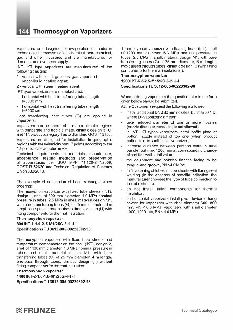
Technical Catalogue
Vaporizers are designed for evaporation of media in technological processes of oil, chemical, petrochemical, gas and other industries and are manufactured for domestic and overseas supply.
INT, IKT type vaporizers are manufactured of the following designs:
1 - vertical with liquid, gaseous, gas-vapor and vapor-liquid heating agent;
2 - vertical with steam heating agent.
IPT type vaporizers are manufactured:
- horizontal with heat transferring tubes length l=3000 mm;
- horizontal with heat transferring tubes length l=6000 мм.
Heat transferring bare tubes (G) are applied in vaporizers.
Vaporizers can be operated in macro climatic regions with temperate and tropic climate. climatic design is “U” and “T”, product category 1 as to Standard GOST 15150.
Vaporizers are designed for installation in geographic regions with the seismicity max 7 points according to the 12-points scale adopted in RF.
Technical requirements to materials, manufacture, acceptance, testing methods and preservation of apparatuses per SOU МPP 71.120-217:2009, GOST R 52630 and Technical Regulation of Customs Union 032/2013.
The example of description of heat exchanger when ordering:
Thermosyphon vaporizer with fixed tube sheets (INT), design 1, shell of 800 mm diameter, 1.0 МPа nominal pressure in tubes, 2.5 МPа in shell, material design М1, with bare transferring tubes (G) of 25 mm diameter, 3 m length, one-pass through tubes, climatic design (U) with fitting components for thermal insulation:
Thermosyphon vaporizer
800 INT-1-1.0-2. 5-М1/25G-3-1-U-I
Specifications ТU 3612-005-00220302-98
Thermosyphon vaporizer with fixed tube sheets and temperature compensator on the shell (IKT), design 2, shell of 1400 mm diameter, 1.6 МPа nominal pressure in tubes and shell, material design М1, with bare transferring tubes (G) of 25 mm diameter, 4 m length, one-pass through tubes, climatic design (T) without fitting components for thermal insulation:
Thermosyphon vaporizer
1400 IKT-2-1.6-1.6-М1/25G-4-1-Т
Specifications ТU 3612-005-00220802-98
Thermosyphon vaporizer with floating head (IpТ), shell of 1200 mm diameter, 6.3 МPа nominal pressure in tubes, 2.5 МPа in shell, material design М1, with bare transferring tubes (G) of 25 mm diameter, 6 m length, two-passes through tubes, climatic design (U) with fitting components for thermal insulation (I):
Thermosyphon vaporizer
1200 IPТ-6.3-2.5-М1/25G-6-2-U-I
Specifications ТU 3612-005-00220302-98
When ordering vaporizers the questionnaire in the form given bellow should be submitted.
At the Customer’s request the following is allowed:
- install additional DN ≤ 80 mm nozzles, but max. 0.1 D, where D - vaporizer diameter;
- take reduced diameter of one or more nozzles (nozzle diameter increasing is not allowed);
- in INT, IKT types vaporizers install baffle plate at bottom nozzle instead of top one (when product bottom inlet in shell side of vaporizer );
- increase distance between partition walls in tube bundle, but max 1000 mm at corresponding change of partition wall cutoff value ;
- the equipment and nozzles flanges facing to be
tongue-and-groove, РN ≤ 4.0 МPа;
- fulfil fastening of tubes in tube sheets with flaring seal welding (in the absence of specific indication, the manufacturer chooses the type of tube connection to the tube sheets).
- do not install fitting components for thermal insulation.
- on horizontal vaporizers install pivot device to hang covers for vaporizers with shell diameter 600, 800 mm, РN < 6.3 МPа, vaporizers with shell diameter 1000, 1200 mm, РN < 4.0 МPа .
Thermosyphon Vaporizers 144

Heat Exchagers
Note: Allowed to manufacture vaporizer shell of tubes with outer diameter 630 mm.
Basic Parameters of Thermosyphon Vaporizers145
INT
600; 800; 1000; 1200; 1400; 1600; 1800; 2000;
2200
1.0;1.6;2.5; 4.0
1.0; 1.6; 2.5
1.0; 1.6
1.0; 1.6; 2.5; 4.0
1.0; 1.6; 2.5
1.0; 1.6
40-1240
from -70 up to +350
2000; 3000; 4000
3000; 4000
25 х 2
1
1.6; 2.5
3000; 6000
IPT
40-464
600; 800; 1000; 1200
from -70
up to + 450
1.6; 2.5; 4.0; 6.3
-
-
25 х 2; 25 х 2.5
2; 4; 6
Parameter value for vaporizers
IКТ
600; 800; 1000; 1200; 1400
1.0; 1.6
-
1.0; 1.6
-
Diagram - on tops of equilateral triangles Spacing - 32
600-1000
1200
1400
1600-2000
2200
600-1000
1200
1400
1600-2000
2200
600-1000
1200-2200
Parameter
2Heat exchanging surface, m
Shell inner diameter, mm(of sheet steel)
Temperature of heating agent and evaporant (T±5), °С
Heat transferring tubes outer diameter and wall thickness, mm
Passes through tubes number
Diagram and spacing of heat transferring tubeslayout in tube sheets, mm
Nominal pressure, MPa, maxin shell for vaporizers with
diameter, mm
Heat transferring tubes length,mm for vaporizers with
diameter, mm
Nominal pressure, MPa, maxin shell for vaporizers with
diameter, mm

Technical Catalogue
Vap
ori
zers
of
INT
an
d IK
T t
yp
e-
desig
n 1
DN
– in
let
(outle
t) o
f pro
duct
DN
1 –
inle
t of pro
duct
Dn
2 –
outle
t of pro
duct
vapour
DN
40
Dra
inage
H1
A2
H
DN
1
х
х
х
х
DN
A l3 DB
l2
х
х
х
х
l1*
A0
A1
Н1
l - tube le
ngth
~L
Thermosyphon Vaporizers of INT and IKT Types - Design 1146
DN
DN
2

Heat Exchagers
Исп
ар
ите
ли
ти
па И
НТ
и И
КТ
исп
ол
нен
ия
2
Thermosyphon Vaporizers of INT and IKT Types - Design 2147
DN
40
Dra
inage
H1
A2
H
DN
1
х
х
х
х
DN
A
l3
DB
l2
х
х
х
х
l1*
A0
A1
Н1
l - tube le
ngth
~L
DN
2
DN
3
DN
– in
let
of va
pour
DN
1 –
inle
t of pro
duct
Dn
2 –
outle
t of pro
duct
vapour
Dn
3 –
outle
t of co
ndensa
te

Technical Catalogue
1.0
2000
3000
4000
1750
2750
3750
1830
2830
3830
280
395
325
300
400
490
275
275
310
5 9 11
2 2 3
3600
4600
5600
1.6
2000
3000
4000
1750
2750
3750
1810
2810
3810
250
390
330
250
475
495
275
275
310
5 9 11
2 2 3
3590
4590
5590
2.5
2000
3000
4000
1725
2725
3725
1790
2790
3790
275
270
275
275
310
5 9 11
2 2 3
3700
4700
5700
60
0
4.0
**
2000
3000
4000
1700
2700
3700
1785
2785
3785
300
275
435
380
200
200
100
250
350
490
510
275
260
310
5 9 11
2 2 3
530
530
3700
4700
5700
1.0
2000
3000
4000
1725
2725
3725
1790
2790
3790
340
460
360
400
625
690
260
340
310
5 7 11
2 2 3
4920
5920
6920
1.6
2000
3000
4000
1725
2725
3725
1760
2760
3760
275
320
500
400
300
500
640
705
260
340
310
5 7 11
2 2 3
4050
5050
6050
2.5
2000
3000
4000
1700
2700
3700
1735
2735
3735
300
325
260
340
310
5 7 11
2 2 3
630
4080
5080
6080
80
0
2000
3000
4000
1675
2675
3675
1725
2725
3725
325
335
520
465
250
250
150
300
400
595
720
260
340
310
5 7 11
2 2 3680
680
4080
5080
6080
1.0
2000
3000
4000
1675
2675
3675
1750
2750
3750
350
425
400
700
830
820
450
480
480
3 5 7
2 2 3
4450
5450
6450
1.6
2000
3000
4000
1675
2675
3675
1720
2720
3720
325
330
600
475
785
900
450
480
480
3 5 7
2 2 3
4450
5450
6450
2.5
2000
3000
4000
1650
2650
3650
1705
2705
3705
350
345
450
480
480
3 5 7
2 2 3
730
4570
5570
6570
10
00
2000
3000
4000
1625
2625
3625
1685
2685
3685
375
365
640
515
300
300
200
350
600
805
910
450
480
480
3 5 7
1000
2 2 3780
780
4570
5570
6570
4.0
**
4.0
**
Н ±
3Н
1 ±
3≈
L
Pa
rtit
ion
wa
lls
la
yo
ut
Fo
r d
esig
n
2
l3
Quantity
Fo
r d
esig
n1
12
2
l2 ±
3
l3
Quantity
DN
2D
N1
DN
3D
N
l1*
A2
±3
A1 ±
3
Fo
r d
esig
ns
Pressure in tubes and shell, PN, МPа
l-K
12
12
Shell inner diameter, Di
A0 ±
3A
±5
Basic
dim
en
sio
ns o
f IN
Т-1
, IN
Т-2
, IК
Т-1
, IК
Т-2
va
po
rize
rs
Dim
ensi
ons,
mm
148 Basic Dimensions of INТ-1, INT-2, IKТ-1, IКТ-2 Vaporizers

Heat Exchagers
** P
ress
ure
in s
hell.
Pre
ssure
in tubes ≤
2,5
МP
а.
Note
s:
1. P
ress
ure
in tubes
must
be le
ss than p
ress
ure
in s
hell.
я в
кож
ухе. If p
ress
ure
in tubes
is le
ss than p
ress
ure
in s
hell,
dim
ensi
ons
А1,
А0,
l3,
DN
, D
N3, Н
are
chose
n d
ependin
g o
n p
ress
ure
in s
hell,
all
oth
er
dim
ensi
ons
are
chose
n d
ependin
g o
n p
ress
ure
in t
ubes.
2. IK
T-1
, IK
T-2
vaporize
rs a
re a
pplie
d w
ith s
hell
of 600 -
1400 m
m d
iam
ete
r, p
ress
ure
D
N ≤
1.6
МP
а.
3. A
t tu
be le
ngth
2000 a
nd 3
000 m
m K
=5
, at tu
be le
ngth
4000 m
m K
=10.
Contin
uatio
n s
heet
1.0
3000
4000
2600
3600
2710
3710
750
480
500
800
955
900
5 72 3
1.6
3000
4000
2600
3600
2660
3660
420
685
540
400
925
915
5 72 3
1200
2.5
3000
4000
2600
3600
264
53645
400
405
780
615
350
350
250
400
700
945
935
450
5 7
2 3
830
880
1.0
3000
4000
262
53625
2695
3695
435
875
565
500
900
1100
900
5 72 3
1.6
3000
4000
2625
3625
2655
3655
425
785
610
400
1070
910
5 72 3
1400
2.5
3000
4000
2625
3625
2630
3630
375
420
880
710
350
350
250
500
800
1090
950
460
5 72 3
990
1030
1.0
3000
4000
2550
3550
2610
3610
540
890
650
600
1230
900
780
650
5 7
2 3
1.6
3000
4000
255
03550
2575
3575
450
525
915
690
500
1000
1245
910
780
650
5 7
2 31600
2.5
3000
4000
2525
3525
254
03540
475
510
930
805
400
600
800
1165
950
780
650
3 5
2 3
1090
1130
1.0
3000
4000
2525
3525
2590
359
0560
975
745
600
1360
105
0760
630
3 5
2 3
1.6
3000
4000
2525
3525
2550
3550
475
550
1035
775
500
11
00
1375
1060
760
630
3 5
2 31800
2.5
3000
4000
2480
3480
2530
3530
520
520
1085
900
400
400
300
1000
1345
1110
760
630
3 5
2 3
1190
1230
1.0
3000
4000
2425
3425
2515
3515
635
1060
785
700
1480
1180
610
560
3 5
2 3
1.6
3000
4000
2425
3425
2475
3475
575
625
1120
825
600
1200
1510
1190
610
560
3 5
2 32000
2.5
3000
4000
2380
3380
2455
3455
620
595
119
0970
500
500
400
700
1100
1480
1245
610
560
3 5
2 3
1290
1330
1.0
3000
4000
2400
3400
2500
3500
1190
865
700
1400
1640
1273
630
560
3 5
2 32200
1
.6 3000
4000
2400
3400
2450
3450
600
650
1195
915
500
600
400
800
1300
1675
1290
630
56
0
3 5
1000
2 3
1390
1430
5860
6860
5860
6860
6060
7060
6390
7290
6310
7310
6530
7530
6750
7750
6820
7820
6850
7860
7200
8200
7320
8320
7460
8460
7500
8500
7650
8650
7830
8830
7970
8970
8080
9080
149 Basic Dimensions of INТ-1, INT-2, IKТ-1, IКТ-2 VaporizersD
imensi
ons,
mm
Н ±
3Н
1 ±
3≈
L
Pa
rtit
ion
wa
lls
la
yo
ut
Fo
r d
esig
n
2
l3
Quantity
Fo
r d
esig
n1
12
2
l2 ±
3
l3
Quantity
DN
2D
N1
DN
3D
N
l1*
A2
±3
A1 ±
3F
or
desig
ns
Pressure in tubes and shell,
PN, МPа
l-K
12
12
Shell inner diameter,
Di
A0 ±
3A
±5

Technical Catalogue
IPT
vap
ori
zers
wit
h h
eat
tran
sfe
rrin
g t
ub
es len
gth
l =
3000 m
m
DN
– in
let (o
utle
t) o
f heatin
g a
gent
DN
1
– in
let of liq
uid
pro
duct
Dn
2
– o
utle
t of pro
duct
vap
ours
l1*
х
х
х
х
1500
±3
DN
2
DB
х
~L
х
х
х
хD
N
l2
A
1500 ±
3
3000 -
tube le
ngth
h
DN
1
H/2
B
х
х
х
Dn25
Air v
alv
e
Dn25
Dra
inage
150 IPT Vaporizers with Tube Length 3000 mm
H/2
DN
H/2 H/2

Heat Exchagers
IPT
vap
ori
zers
heat
tran
sfe
rrin
g t
ub
es len
gth
l =
6000 m
m
х
х
х
х
1500 ±
3
х
х
х
х
х
A
3000 ±
3
6000 -
tube le
ngth
B
х
х
х
аа
151 IPT Vaporizers with Tube Length 6000 mm
l1*
DN
2
DB
~L
DN
l2
DN
1
H/2 H/2
DN
H/2 H/2
DN
2
DN
1
Dn25
Air v
alv
e
Dn25
Dra
inage
h
DN
– in
let (o
utle
t) o
f heat agent
DN
1
– in
let of liq
uid
pro
duct
Dn
2
– o
utle
t of pro
duct
vap
our
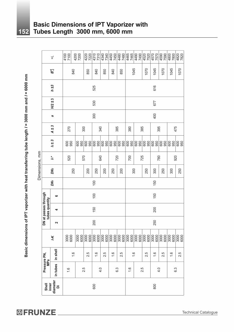
Technical Catalogue
Basic
dim
en
sio
ns o
f IP
T v
ap
ori
zer
wit
h h
eat
tran
sfe
rrin
g t
ub
e len
gth
l =
3000 m
m a
nd
l =
6000 m
m
4100
7100
1.6
3000
6000
520
600
950
270
1.6
3000
6000
250
600
950
4200
7200
2.5
2.5
3000
6000
200
570
600
950
300
4220
7220
1.6
3000
6000
250
600
950
4310
7310
4.0
2.5
3000
6000
200
640
600
950
340
4340
7340
1.6
3000
6000
250
600
950
4450
7450
600
6.3
2.5
3000
6000
200
150
100
100
200
720
600
950
385
300
530
525
4480
7480
1.6
3000
6000
700
600
950
380
4465
74
65
1.6
3000
6000
300
600
950
4490
74
90
2.5
2.5
3000
6000
250
725
600
950
385
4520
7520
1.6
3000
6000
300
600
950
4570
7570
4.0
2.5
3000
6000
250
780
600
950
395
4590
7590
1.6
3000
6000
300
600
950
4800
7800
800
6.3
2.5
3000
6000
250
200
150
150
250
920
600
950
475
400
677
616
840
850
840
850
840
850
1045
1070
1045
1070
1045
1070
4820
7820
152Basic Dimensions of IPT Vaporizer withTubes Length 3000 mm, 6000 mm
Dim
ensi
ons,
mm
B+
6 -3a
H/2
± 3
h ±
3≈L
DN
2A
± 3
l2 ±
3l1
*D
N1
DN
at
passes t
hro
ug
h t
ub
es q
uan
tity
24
6l-
KМ
Pа
Pre
ssu
re P
N,
Sh
ell
inn
er
dia
mete
rD
iin
tu
bes
in s
hell

Heat Exchagers
1.6
3000
6000
790
600
950
395
4670
7670
1.6
3000
6000
350
600
950
1250
4710
7710
2.5
2.5
3000
6000
300
830
600
950
420
1285
4770
7770
1.6
3000
6000
350
600
950
1250
4940
7940
4.0
2.5
3000
6000
300
960
600
950
490
1285
4960
7960
1.6
3000
600
0350
600
950
1250
5250
8250
1000
6.3
2.5
3000
6000
200
150
200
300
1150
600
950
590
500
779
716
1285
5270
8270
1.6
880
420
7900
1.6
400
1550
7950
2.5
2.5
350
940
455
1610
8030
1.6
400
1550
8100
4.0
2.5
350
1100
530
1610
8180
1.6
400
1550
8530
1200
6.3
2.5
6000
300
250
200
250
350
1300
900
660
600
890
820
1610
8550
Contin
uatio
n s
heet
153Basic Dimensions of IPT Vaporizer withTubes Length 3000 mm, 6000 mm
Dim
ensi
ons,
mm
B+
6 -3a
H/2
± 3
h ±
3≈L
DN
2A
± 3
l2 ±
3l1
*D
N1
DN
at
passes t
hro
ug
h t
ub
es q
uan
tity
l-K
МP
аP
ressu
re P
N,
Sh
ell
inn
er
dia
mete
rD
i2
46
in t
ub
es
in s
hell

Technical Catalogue
Heat
exch
an
ge s
urf
ace a
s t
o t
ub
es o
ute
r d
iam
ete
r a
nd
are
a
of
cle
ar
op
en
ing
s t
hro
ug
h t
ub
e a
nd
sh
ell s
ides o
f IN
T a
nd
IK
T v
ap
ori
zers
Heat
exch
an
ge s
urf
ace, m
2
at
tub
e len
gth
, m
mA
rea o
f cle
ar
op
en
ing
th
rou
gh
sh
ell s
ide*,
m2
Betw
een
part
itio
n w
alls a
t tu
be len
gth
, m
mS
hell in
ner
dia
mete
r,
Di, m
m
2000
3000
4000
Are
a o
fcle
ar
op
en
ing
of
on
e p
ass
thro
ug
h t
ub
es,
m2
in s
lot
2000
3000
4000
600
40
60
80
0.0
88
0.0
45
0.0
48
0.0
45
0.0
54
800
74
112
149
0.1
64
0.0
70
0.0
58
0.0
76
0.0
68
1000
119
179
238
0.2
63
0.1
15
0.1
01
0.1
05
0.1
08
1200
-262
350
0.3
86
0.1
70
-0
.123
0.1
23
1400
-371
494
0.5
45
0.2
08
-0
.149
0.1
49
1600
-479
639
0.7
04
0.2
93
-0
.292
0.2
43
1800
-614
819
0.9
02
0.3
63
-0
.323
0.2
67
2000
-756
1009
1.1
12
0.4
49
-0
.289
0.2
66
2200
-930
1240
1.3
66
0.5
07
-0
.330
0.2
94
* A
rea o
f cl
ear
openin
g thro
ugh s
hell
side
is g
iven for
vaporize
rs o
f desi
gn 1
. N
ote
: H
eat exc
hange s
urf
ace
is g
iven n
ot
incl
udin
g tube s
heet th
ickn
ess
154 Heat Exchange Surface of INT and IKT Vaporizers

Heat Exchagers
Note: Heat exchange surface is given not including tube sheet thickness
до 100 200 250
300 350 400* 425* 450*
1.0 1.00 0.93 0.90 0.75 0.66 0.58 0.50 0.36
1.6 1.60 1.49 1.40 1.20 1.10 0.90 0.80 0.57
2.5** 2.50 2.32 2.25 1.90 1.70 1.50 1.30 0.90
4.0** 4.00 3.72 3.50 3.00 2.60 2.30 2.00 1.40
6.3* 6.30 6.00 5.40 4.80 4.00 3.70 3.20 2.30
* Only for FHTE-type machines.** Only for immovable tube sheet thermosiphon evaporators (ITTE) and FHTE-type machines
4
6
2
4
6
2
4
6
2
4
6
2
600
800
1000
1200
25х225х2.5
25х225х2.5
25х225х2.5
25х225х2.5
25х225х2.5
25х225х2.5
25х225х2.5
25х225х2.5
25х225х2.5
25х225х2.5
25х225х2.5
25х225х2.5
-
3000
50
44
40
95
86
83
155
144
139
-
-
166
6000
100
88
81
191
172
310
288
279
464
435
424
0.0310.034
0.0110.012
0.0070.008
0.0610.067
0.0270.030
0.0160.017
0.1010.111
0.0430.048
0.0270.030
0.1510.167
0.0640.071
0.0420.047
155
Heat Exchange Surface Along the Outside Pipe Diameter and the Area of Clear Openings in the Pipes of Floating Head Thermosyphon Evaporators (FHTE)
Shell innerdiameter, Di, mm
Heat exchange surface, m2
at tube length, mmArea of
clear openingof one pass
through tubes,m2
Quantity ofpasses
through tubes
Maximum design pressure, МPа, at medium temperature, °С Nominal pressure PN,МPа
Maximum design pressure of heat exchangers depending on medium temperature
Tubes assortment,
mm

Technical Catalogue
Shell inner diameter, DiAllowable load on landing pad,
НL1 ± 6 d
600 25000 1006 24
800 63000 1300 35
1000 1538
1200100000
1812
1400 2020
1600160000
2300
1800 250000 2600
42
2000 2900
2200400000
310050
Layout of foundation bolts holes for IPT vaporizers
Movable support Fixed support
For shells of 600 mm diameter For shells of 800-1200 mm diameter
Movable support Fixed support
Inner diameter, Di
600 450 600 - 180 800 500 740
1000 650 1000
1200 800 1100
140 250
d
DN1, DN2L1
2holesØ28
А1
А
А3
I
80
28
R14
I
36
R18
II
80
II
156Layout of Nozzles, Foundation Bolts Holes forINT and IKT Vaporizers
DN, DN3
А1
А
А3
А1
А
А2
А3
А1
А
А2
А3
4holesØ36
А3А1А
Dimensions, mm
Dimensions, mm

Heat Exchagers
Mate
rials
fo
r vap
ori
zers
assem
bly
un
its, m
ain
part
s a
nd
co
mp
on
en
ts m
an
ufa
ctu
rin
g
Ma
teri
als
Va
po
rize
r ty
pe
INT
IKT
IPT
INT
IK
TIP
T
INT
INK
Va
po
rize
rm
ate
ria
l d
es
ign
157 Materials for Vaporizers Manufacturing
Ap
pli
ca
tio
nte
mp
era
ture
lim
it,
°C
fro
m -
30
to
+3
50
fro
m -
30
to
+4
50
fro
m -
30
to
+2
00
dis
trib
uti
ng
ch
am
be
r
Ste
el С
т 3
сп a
s to
Sta
nd
ard
GO
ST
38
0,
GO
ST
14
63
7S
tee
l 16
ГС*
as
to G
OS
T 5
52
0
sh
ell
an
d s
he
ll c
ov
er
tub
es
tub
e s
he
et
М1
Ste
el С
т3сп
as
to S
tan
da
rd G
OS
T 3
80
,G
OS
T 1
46
37
Ste
el 1
6ГС
as
to G
OS
T 5
52
0.
Tu
be
s -
ste
el 2
0 a
s to
Sta
nd
ard
GO
ST
10
50
, G
OS
T 8
73
1 g
r. B
Ste
el 1
0 a
nd
20
as
toS
tan
da
rd 1
05
0,
GO
ST
55
0 g
r.A
,G
OS
T 8
73
3 g
r. B
Ste
el 1
6ГС
* a
s to
G
OS
T 5
52
0o
r G
OS
T 8
47
9 g
r.IV
, G
OS
T 1
92
81
М8
fro
m -
70
to
+3
50
S
tee
l 12
Х1
8Н
10
Т a
s to
GO
ST
56
32
an
d G
OS
T 7
35
0 g
r. М
2б
Ste
el 0
8Х
18
Н1
0Т
,1
2Х
18
Н1
0Т
as
toG
OS
T 5
63
2,
GO
ST
99
41
Ste
el 1
2Х
18Н
10Т
as
to S
tandard
GO
ST
5632 g
r. M
2б
, G
OS
T 2
5054 g
r. IV
and T
ech
nic
al D
ocu
ments
appro
ved in
acc
ord
ance
with
est
ablis
hed p
roce
dure
М1
0
Ste
el 1
2Х
18
Н1
0Т
as
to G
OS
T 5
63
2a
nd
GO
ST
73
50
gr. М
2б
Ste
el 0
8Х
18
Н1
0Т
,1
2Х
18
Н1
0Т
as
toG
OS
T 5
63
2,
GO
ST
99
41
Ste
el 1
2Х
18Н
10Т
as
to S
tandard
GO
ST
5632 g
r. M
2б
, G
OS
T 2
5054 g
r. IV
and T
ech
nic
al D
ocu
ments
appro
ved in
acc
ord
ance
with
est
ablis
hed p
roce
dure
М11
Ste
el 1
0Х
17
Н1
3М
2Т
as
to G
OS
T 5
63
2a
nd
GO
ST
73
50
gr. М
2б
Ste
el 1
0Х
17
Н1
3М
2Т
as
to G
OS
T 5
63
2,
GO
ST
99
41
Ste
el 1
0Х
17Н
13М
2Т
as
to S
tandard
GO
ST
5632, G
OS
T 7
350 g
r. M
2б
, G
OS
T 2
5054 g
r. IV
and T
ech
nic
al D
ocu
ments
appro
ved in
acc
ord
ance
with
est
ablis
hed p
roce
dure
М9
fro
m -
70
to
+3
50
S
tee
l 10
Х1
7Н
13
М2
Т a
s to
GO
ST
56
32
an
d G
OS
T 7
35
0 g
r. М
2б
Ste
el 1
0Х
17
Н1
3М
2Т
as
to G
OS
T 5
63
2,
GO
ST
99
41
Ste
el 1
0Х
17Н
13М
2Т
as
to S
tandard
GO
ST
5632, G
OS
T 7
350 g
r. M
2б
, G
OS
T 2
5054 g
r. IV
and T
ech
nic
al D
ocu
ments
appro
ved in
acc
ord
ance
with
est
ablis
hed p
roce
dure
INT
IK
TIP
T

Technical Catalogue
158 Materials for Vaporizers Manufacturing
Ste
el 0
9Г2С
as
to G
OS
T 5
520, G
OS
T 1
9281.
Tubes
- st
eel 1
0Г2 a
s to
GO
ST
8731 g
r. В
an
dTe
chn
ica
l Do
cum
en
ts a
pp
rove
d
in a
cco
rda
nce
with
est
ab
lish
ed
pro
ced
ure
tub
e s
heet
Ste
el 0
9Г2С
and 1
0Г2С
1 a
s to
GO
ST
5520,
09Г2С
as
toG
OS
T 1
928 a
nd 1
0Г2
as
toG
OS
T 4
543, G
OS
T 8
479 g
r. IV
Ste
el 0
8Х
22Н
6Т
as
to S
tandard
GO
ST
5632 g
r. M
2б
, G
OS
T 2
5054 g
r. IV
and T
ech
nic
al D
ocu
ments
appro
ved in
acc
ord
ance
with
est
ablis
hed p
roce
dure
Ste
el 0
8Х
22Н
6Т
as
to S
tandard
GO
ST
5632 g
r. M
2б
, G
OS
T 2
5054 g
r. IV
and T
ech
nic
al D
ocu
ments
appro
ved in
acc
ord
ance
with
est
ablis
hed p
roce
dure
tub
es
Ste
el 1
0Г2 a
s to
GO
ST
550 (
gr.
A),
GO
ST
8733
(gr.
B)
Ste
el 0
8Х
22Н
6Т
as
toG
OS
T 5
63
2 a
nd
GO
ST
99
41
Ste
el 0
8Х
22Н
6Т
as
toG
OS
T 5
632 a
nd
Tech
nic
al
Docu
ments
appro
ved
in a
ccord
ance
with
est
ablis
hed p
roce
dure
Contin
uatio
n s
heet
** I
t is
allo
wed to
apply
in a
gre
em
ent w
ith m
anufa
cture
r.N
ote
: 1.
It i
s allo
wed t
o m
ake
out
ass
em
bly
units
of
anoth
er
mate
rials
of
gra
de
s pro
vided i
n I
ndust
ria
l S
tandard
OS
T 2
6-2
91,
whic
h c
orr
esp
ond t
o
mate
rials
speci
fied in
the ta
ble
by
mech
anic
al p
ropert
ies
and c
orr
osi
on resi
stance
.2.
All
mate
rials
applie
d fo
r vaporize
rs m
anufa
cturing m
ust
be c
ert
ified.
Ma
teri
als
fo
r v
ap
ori
zers
as
se
mb
ly u
nit
s,
ma
in p
art
s a
nd
co
mp
on
en
ts m
an
ufa
ctu
rin
g
sh
ell a
nd
sh
ell c
over
Ste
el С
т3сп
as
to G
OS
T 3
80,
GO
ST
4637
Tu
be
s -
ste
el 2
0 a
s to
Sta
nd
ard
GO
ST
10
50
, G
OS
T 8
73
1 g
r. B
dis
trib
uti
ng
ch
am
ber
Ste
el 0
8Х
22Н
6Т
as
toG
OS
T 5
632 a
nd
GO
ST
7350 g
r. М
2б
Ste
el 0
8Х
22Н
6Т
as
toG
OS
T 5
632 a
nd
GO
ST
7350 g
r. М
2б
from
-60 to +
450
from
-30 to +
200
М17
М23**
М24**
from
-60 to +
350
INТ
IКТ
IPТ
INТ
IКТ
Ap
pli
ca
tio
nte
mp
era
ture
lim
it,
°C
Va
po
rize
rm
ate
ria
l d
es
ign
Va
po
rize
r ty
pe

Heat Exchagers
1.0 1450 1850 2260
1.6 1480 1880 22801.0
2.5 1560 1890 2420
1.6 1565 1900 24301.6
2.5 1570 1940 2440
2.5 1710 2140 2570
600
2.54.0 2100 2500 2900
1.0 2350 3020 3730
1.6 2460 3170 39101.0
2.5 2570 3290 4030
1.6 2600 3300 40401.6
2.5 2650 3370 4120
2.5 2900 3630 4370
800
2.54.0 3400 4130 4900
1.0 3900 4950 6100
1.6 3980 5050 64001.0
2.5 4200 5390 6600
1.6 4350 5450 66501.6
2.5 4450 5700 6700
2.5 5000 6100 7250
100
2.54.0 5800 6800 7800
1.0 - 7000 8760
1.6 - 7300 93001.0
2.5 - 7410 9550
1.6 - 8050 99801.6
2.5 - 8300 10150
1200
2.5 2.5 - 9390 11300
159 Weight of INT and IKT Vaporizers
Weight, kg, at tube length, mm
Shell inner diameter,
Di, mm
Pressure in tubes,PN, МPа
Pressure in shell,PN, МPа 2000 3000 4000

Technical Catalogue
1.0 - 9940 12480
1.6 - 10150 128801.0
2.5 - 10800 13430
1.6 - 11020 135801.6
2.5 - 11440 14080
1400
2.5 2.5 - 13050 15410
1.0 - 12420 15300
1.6 - 12930 158501.0
2.5 - 13520 16880
1.6 - 13900 170001.6
2.5 - 14590 17880
1600
2.5 2.5 - 16300 19200
1.0 - 15380 19240
1.6 - 16180 199401.0
2.5 - 17380 20840
1.6 - 18030 216201.6
2.5 - 19230 23140
1800
2.5 2.5 - 20310 24320
1.0 - 20000 24350
1.6 - 20570 250801.0
2.5 - 21320 27480
1.6 - 22640 280001.6
2.5 - 24400 29150
2000
2.5 2.5 - 26820 31570
1.01.0 - 24900 28750
1.6 - 26820 324502200
1.6 1.6 - 26940 34700
Note:1. Weight of INT, IKT vaporizers is calculated for nominal thickness of sheet metal without weight of fitting and components. 2. Allowance from weight value must not exceed +8%.
Continuation sheet
160 Weight of INT and IKT Vaporizers
Weight, kg, at tube length, mm
Shell inner diameter,
Di, mm
Pressure in tubes,PN, МPа
Pressure in shell,PN, МPа 2000 3000 4000

Heat Exchagers
Weight, kg
For 25х2 tubes of length For 25х2.5 tubes of length
in tubes
in shell 3000 6000 3000 6000
2 passes through tubes
1.6 1.6 2500 3880 2670 4220
1.6 2630 3960 2800 4330 2.5
2.5 2780 4280 2950 4620
1.6 3090 4460 3260 4800 4.0
2.5 3320 4820 3490 5160
1.6 3800 5200 3970 5540 6.3
2.5 3950 5470 4120 5810
4 passes through tubes
1.6 1.6 2460 3750 2610 4050
1.6 2590 3830 2740 4160 2.5
2.5 2740 4150 2890 4450
1.6 3060 4340 3210 4640 4.0
2.5 3290 4700 3440 5000
1.6 3770 5090 3920 5390 6.3
2.5 3920 5360 4070 5660
6 passes through tubes
1.6 1.6 2470 3710 2600 3980
1.6 2600 3790 2740 4100 2.5
2.5 2750 4110 2890 4390
1.6 3070 4300 3210 4580 4.0
2.5 3300 4660 3440 4940
1.6 3790 5060 3930 5330
600
6,3 2.5 3940 5330 4080 5600
161
Pressure PN, МPа
Weight of IPT Vaporizers
Shell inner diameter,
Di, mm

Technical Catalogue
2 passes through tubes
4050 6400 4380 7060
4430 6830 4760 7490
4770 7360 5100 8010
5170 7500 5500 8160
5540 8090 5860 8750
6660 8990 6990 9650
7010 9590 7340 10250
4 passes through tubes
3990 6200 4290 6800
4370 6640 4670 7240
4710 7170 5010 7760
5120 7320 5420 7920
5490 7910 5780 8510
6610 8810 6910 9410
6960 9410 7260 10010
6 passes through tubes
4030 6190 4310 6770
4420 6630 4710 7210
4760 7160 5050 7730
5180 7320 5460 7900
5550 7910 5820 8490
6670 8820 6960 9390
800
7020 9420 7310 9990
Continuation sheet
162 Weight of IPT Vaporizers
3000 6000 3000 6000
Weight, kg
For 25х2 tubes of length For 25х2.5 tubes of lengthShell inner diameter,
Di, mm
Pressure PN, МPа
in tubes in shell
1.6 1.6
1.62.5
2.5
1.64.0
2.5
1.66.3
2.5
1.6 1.6
1.62.5
2.5
1.64.0
2.5
1.66.3
2.5
1.6 1.6
1.62.5
2.5
1.64.0
2.5
1.66.3
2.5

Heat Exchagers
2 passes through tubes
6510 10260 7040 11320
7040 10800 7570 11860
7590 11700 8120 12760
8280 12050 8810 13110
8830 12920 9360 13990
11030 14800 11560 15850
11550 15660 12100 16720
4 passes through tubes
6460 10040 6950 11030
6990 10590 7490 11580
7540 11490 8040 12480
8250 11860 8740 12840
8800 12730 9290 13720
11020 14630 11510 15600
11540 15490 12050 16470
6 passes through tubes
6500 10050 6700 11000
7070 10600 7550 11560
7620 11500 8100 12460
8340 11880 8820 12840
8890 12750 9370 13720
11130 14680 11610 15620
1000
11650 15540 12150 16490
Continuation sheet
163 Weight of IPT Vaporizers
3000 6000 3000 6000
Weight, kg
For 25х2 tubes of length For 25х2.5 tubes of lengthShell inner diameter,
Di, mm
Pressure PN, МPа
in tubes in shell
1.6 1.6
1.62.5
2.5
1.64.0
2.5
1.66.3
2.5
1.6 1.6
1.62.5
2.5
1.64.0
2.5
1.66.3
2.5
1.6 1.6
1.62.5
2.5
1.64.0
2.5
1.66.3
2.5

Technical Catalogue
2 passes through tubes
9360 14700 10150 16290
10180 15530 10980 17120
10810 16450 11600 18040
12310 17660 13100 19250
13080 18660 13870 20250
15640 21000 16430 22590
16310 21870 17100 23460
4 passes through tubes
9320 14450 10060 15940
10150 15290 10910 16790
10780 16210 11520 17710
12310 17450 13050 18940
13080 18450 13820 19940
15670 20820 16410 22320
16340 21690 17080 23190
6 passes through tubes
9450 14500 10180 15960
10300 15360 11030 16820
10930 16280 11650 17740
12480 17540 13200 19000
13250 18540 13970 20000
15870 20940 16590 22400
1200
16540 21810 17260 23270
Note:1. Weight of IPT vaporizers is calculated for nominal thickness of sheet metal net of weight of fittings and components. 2. Allowance from weight value must not exceed +8%.3. For IPT vaporizers Ø25x2 mm tubes ate made of high alloy steels, Ø25x2.5 mm tubes are made of carbonic steels.
Continuation sheet
164 Weight of IPT Vaporizers
3000 6000 3000 6000
Weight, kg
For 25х2 tubes of length For 25х2.5 tubes of lengthShell inner diameter,
Di, mm
Pressure PN, МPа
in tubes in shell
1.6 1.6
1.62.5
2.5
1.64.0
2.5
1.66.3
2.5
1.6 1.6
1.62.5
2.5
1.64.0
2.5
1.66.3
2.5
1.6 1.6
1.62.5
2.5
1.64.0
2.5
1.66.3
2.5
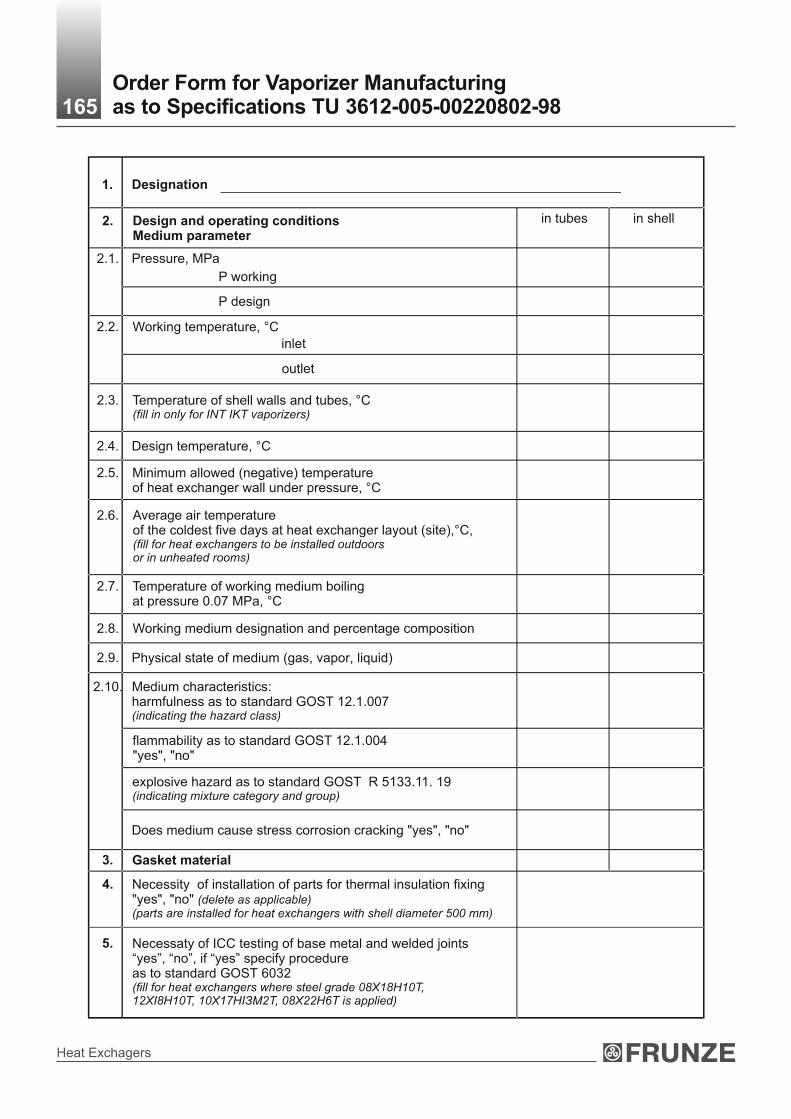
Heat Exchagers
165Order Form for Vaporizer Manufacturing as to Specifications ТU 3612-005-00220802-98
Designation
Design and operating conditionsMedium parameter
in tubes in shell
Pressure, МPа
Р working
Р design
Working temperature, °С
inlet
outlet
Temperature of shell walls and tubes, °С(fill in only for INT IKT vaporizers)
Design temperature, °С
Minimum allowed (negative) temperatureof heat exchanger wall under pressure, °С
Average air temperatureof the coldest five days at heat exchanger layout (site),°С, (fill for heat exchangers to be installed outdoors or in unheated rooms)
Temperature of working medium boiling at pressure 0.07 МPа, °С
Working medium designation and percentage composition
Physical state of medium (gas, vapor, liquid)
Medium characteristics:harmfulness as to standard GOST 12.1.007 (indicating the hazard class)
flammability as to standard GOST 12.1.004 "yes", "no"
explosive hazard as to standard GOST R 5133.11. 19 (indicating mixture category and group)
Does medium cause stress corrosion cracking "yes", "no"
Gasket material
Necessity of installation of parts for thermal insulation fixing"yes", "no" (delete as applicable)(parts are installed for heat exchangers with shell diameter 500 mm)
1.
2.
2.1.
2.2.
2.3.
2.4.
2.5.
2.6.
2.7.
2.8.
2.9.
2.10.
3.
4.
5. Necessaty of ICC testing of base metal and welded joints “yes”, “no”, if “yes” specify procedure as to standard GOST 6032 (fill for heat exchangers where steel grade 08Х18Н10Т, 12XI8H10T, 10X17HIЗМ2Т, 08Х22Н6Т is applied)

Technical Catalogue
166
6. Specify: pivot points "left", "right", "not required" (delete as applicable) (pivot points are installed on horizontal heat exchangers - Ø 600-800 mm at Рn ≤6.3 МPа, 1000-1200 mm at Рn ≤4.0 МPа,
7. Horizontal heat exchangers are installed: "on concrete foundation", "on metal structures" (delete as applicable)
8. Specify type of tube fastening in sheets: "expanding", "seal welding with expanding" (delete as applicable)
9. Seamless tubes "yes", "no" (delete as applicable)
10. Heat exchanger figure with location dimensions of nozzles and supports(for heat exchangers having differences from these specifications)
NOZZLES
Nozzlenumber(No) on figure
Nozzles purpose Nozzles
nominal diameter, mm Nominal pressure, МPа
Notes:
1. Heat exchangers figure should correspond figure given in these Specifications ТU.2. Dimensions are specified if they differ from the dimensions given in these Specifications TU.3. Nozzles nominal diameters are specified if they are less than in these Specifications TU.
11. The content of adopted differences from heat exchanger prototype(differences listed in these Specifications are allowed)
_______________________________________________________________________
_______________________________________________________________________
_______________________________________________________________________
_______________________________________________________________________
Order Form for heat exchanger manufacturing as to Specification ТU 3612-005-00220302-98 is not subject to be agreed. Name of the Company-User and process plant or line - Name and postal address of the Company that filled Order Form
Signature of the head of the Company that filled Order Form
________________ _____________________ ____________________ (Title) (Signature) (Print full name)
_____________________(Date)
Order Form for Vaporizer Manufacturing as to Specifications ТU 3612-005-00220802-98

Heat Exchagers
Steam-Water and Water-to-Water
Heatersfor Heat Supply Networks

Technical Catalogue
Steam-water and water-to-water heaters are applied to heat water in heating and hot water supply of residential, public and industrial buildings.
Heaters are manufactured in climatic design for operation in temperate regions (U) placement category (indoors placement) as to Standard GOST 15150-69.
Heaters are designed to be installed in regions of seismicity up to 7 points according to 12-point scale adopted in the Russian Federation.
Technical requirements to materials, manufacture, acceptance, testing methods and preservation of apparatuses per SOU МPP 71.120-217:2009, GOST R 52630 and Technical Regulation of Customs Union 032/2013.
The example of heater description when ordering:
Steam-water heater (PP), with 630 mm shell diameter, 3 m heat transferring tubes, 2 passes through tube side, with parts for thermal insulation fixing.
Heater 630 PP-3-2 I
Specifications ТU 3113-028-00220302-01
Steam-Water and Water-to-Water Heatersfor Heat Supply Networks
Water-to-water heater with fixed tube sheets (PVN), with 168 mm shell diameter, 4 m heat transferring tubes, single-stage.
Heater 168 PVN-4-1
Specifications ТU 3113-028-00220302-01
Water-to-water heater with expansion joint on shell (PVK), 273 mm shell diameter, 2 m heat transferring tubes, quantity of heater stages - 4.
Heater 273 PVK-2-4
Specifications ТU 3113-028-00220302-01
Steam-water heaters (PP) can be operated at heat-transfer medium temperature from 0°С up to 300°С, water-to-water heaters - from 0°С up to 200°С.
In design water-to-water heaters are divided into heaters with fixed tube sheets (PVN), with expansion joint on shell (PVK).
Drawing (sketch) requirements
Drawing (sketch) is made in the case of construction features.
Drawing (sketch) should include:
- sketch of heater is made of full thin lines, with main overall and connection dimensions;
- layout of nozzles, manhole, supports, slinging device (for heaters of types 2 and 3), pads for servicing platform (in the case of placement deviation from figures as to the catalogue);
- nozzles changed as to nominal bore, additional nozzles and pads should be made of full main lines ;
- table of nozzles with nozzles designation, nominal bore and nominal pressure;
- technical requirements.
Technical requirements should contain description of heater in accordance with Specifications TU catalogue, list of design differences, necessity of heat treatment for media that cause corrosion cracking, title block in accordance with standard GOST 2.104.
Drawing (sketch) designation, heater designation as to process scheme and heater weight are indicated in the title block.
168
Materials for heaters manufacturing
(it is allowed to use tubes made of steels 10, 20 GOST 1050, GOST 550, GOST 8733, gr.В by agreement with the customer).Heaters are supplied with counter flanges, gaskets and fasteners.All materials applied for heater manufacturing should be certified.
steel Ст3 сп GOST 380-88
steel 20 GOST 1050-88steel 16ГС GOST 5520-79
latten ЛАМШ 70-1 GOST 21646-76
shell, chamberflanges
tube sheets Ø20х2 mm heat transferring tubes

Heat Exchagers
DN1
l3 A A1
C
h2
l2
x x
x x
h
h1
h3
l0
l
L*
l1
x x
x x
Water inlet and outlet
Dn1 - steam inletDN2 - condensate outlet
С
С
Steam-Water Single-Stage Heater 169
DN3 DN2
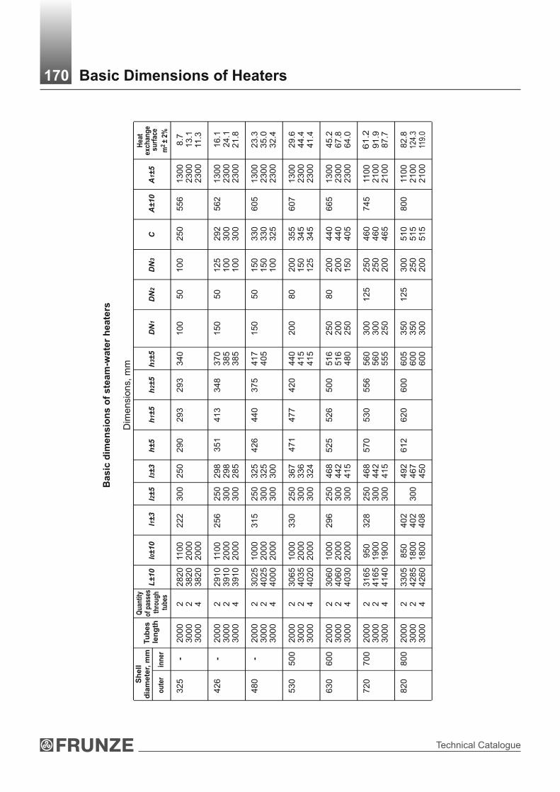
Technical Catalogue
Basic Dimensions of Heaters170
Basic
dim
en
sio
ns o
f ste
am
-wate
r h
eate
rs
Dim
ensi
ons,
mm
Sh
ell
d
iam
ete
r, m
m
ou
ter
inn
er
Tu
be
s l
en
gth
Qua
ntity
of
pas
ses
thro
ugh
tube
s
L±1
0l0
±1
0l1
±3
l2±5
l3±3
h±5
h1±5
h2±5
h3±5
DN
1C
A±1
0A
1±5
Hea
t ex
chan
ge
su
rfac
e
2 m
±2%
DN
2D
N3
34
0
37
03
85
38
5
41
7
44
0
41
54
15
51
65
16
48
0
56
05
60
55
5
60
56
00
60
0
40
5
29
3
41
3
44
0
47
7
52
6
53
0
62
0
29
3
34
8
37
5
42
0
50
0
55
6
60
0
20
0
10
0
15
0
15
0
20
0
25
0
25
0
30
03
00
25
0
35
03
50
30
0
50
50
50
80
80
12
5
12
5
10
0
10
0
12
51
00
10
0
15
01
50
20
01
50
12
5
20
02
00
15
0
25
02
50
20
0
30
02
50
20
0
25
0
29
23
00
30
0
33
03
30
32
5
35
53
45
34
5
44
04
40
40
5
46
04
60
46
5
51
05
15
51
5
55
6
56
2
60
5
60
7
66
5
74
5
80
0
110
0
13
00
13
00
2
30
02
30
0
13
00
2
30
02
30
0
23
00
23
00
13
00
23
00
23
00
13
00
2
30
02
30
0
21
00
21
00
110
0
21
00
21
00
8.7
1
3.1
11
.3
16
.1 2
4.1
21
.8
23
.3 3
5.0
32
.4
29
.6 4
4.4
41
.4
45
.2 6
7.8
64
.0
61
.2 9
1.9
87
.7
82
.8 1
24.3
119
.0
25
0
29
82
98
28
5
32
53
25
30
0
36
7
33
63
24
46
84
42
41
5
46
84
42
41
5
49
24
67
45
0
29
0
35
1
42
6
47
1
52
5
57
0
61
2
30
0
25
03
00
30
0
25
03
00
30
0
25
03
00
30
0
25
03
00
30
0
25
03
00
30
0
30
0
28
20
3
82
03
82
0
29
10
3
91
03
91
0
30
25
4
02
5
40
00
30
65
4
03
5
40
20
30
60
4
06
0
40
30
31
65
4
16
5
41
40
33
05
4
28
5
42
60
110
0
20
00
20
00
110
0
20
00
20
00
10
00
2
00
02
00
0
10
00
2
00
02
00
0
10
00
2
00
02
00
0
95
0
19
00
19
00
85
0
18
00
18
00
22
2
25
6
31
5
33
0
29
6
32
8
40
24
02
40
8
32
5
42
6
48
0
53
0
63
0
72
0
82
0
- - -
50
0
60
0
70
0
80
0
20
00
3
00
03
00
0
20
00
3
00
03
00
0
20
00
3
00
03
00
0
20
00
3
00
03
00
0
20
00
3
00
03
00
0
20
00
3
00
03
00
0
20
00
3
00
03
00
0
2 2 4 2 2 4 2 2
4 2
2 4 2 2 4 2 2 4 2
2 4

Heat Exchagers
Shell diameter, mmQuantity of passes through tubes
Weight, kgouter
325
426
480
530
630
720
820
inner
-
-
-
500
600
700
800
2
675800
9351110
11751410
15551845
20002480
27003310
33604125
4
-775
-1070
-1360
-1790
-2420
-3230
-4030
20003000
20003000
20003000
20003000
20003000
20003000
20003000
Length of heat transferring
tubes, mm
Heat exchange surface of steam-water heaters
Weight of steam-water heaters
Shelldiameter, mm
outer
Tubes assortment, mm
inner
Length of heat transferring
tubes, mm
Quantity of passes
through tubes
Heat exchange surface
2m ±2%
Quantity of heat transferring
tubes
707060
128128116
186186172
236236220
360360340
488488466
660660632
8.713.111.3
16.124.121.8
23.335.032.4
29.644.441.4
45.267.864.0
61.291.987.7
82.8124.3119.0
224
224
224
224
224
224
224
200030003000
200030003000
200030003000
200030003000
200030003000
200030003000
200030003000
20х2
325
426
480
530
630
720
820
-
-
-
500
600
700
800
Heat Exchange Surface of Heaters171

Technical Catalogue
Supports for steam-water heaters must correspond to the diameter specified in the table
Shell diameter, mm
outer innerА2 А3
325
426
480
530
630
720
820
-
-
-
500
600
700
800
330
350
380
450
470
500
400
450
470
500
600
670
740
For shells of 325-720 mm diameter For shells of 800 mm
A2
A3
A
A
R14
8028
140
Layout of Foundation Bolts Holes in Supports172
A2
A3
Dimensions, mm
Limit working pressure for steam-water heaters
Limit working pressure МPа, at medium temperature, °С maxNominal Pressure,
PN, МPадо 100 200 250 300
1.6 1.60 1.49 1.40 1.20
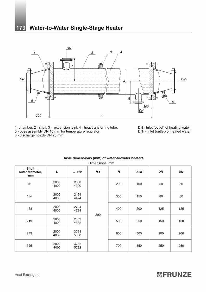
Heat Exchagers
1- chamber, 2 - shell, 3 - expansion joint, 4 - heat transferring tube, 5 - boss assembly DN 10 mm for temperature regulator, 6 - discharge nozzle DN 20 mm
DN - Inlet (outlet) of heating waterDN1 - Inlet (outlet) of heated water
Water-to-Water Single-Stage Heater173
L
х х
х хх х
х х
h
200
300
2 3 4
65
1
DN
DN
h2
DнDN1 DN1
Basic dimensions (mm) of water-to-water heaters
76
114
168
219
273
325400
20004000
20004000
20004000
20004000
20004000
20000
23004300
24244424
27244724
28324832
30385038
32325232
200
200
300
400
500
600
700
100
150
200
250
300
350
50
80
125
150
200
250
50
80
125
150
200
250
L1±10 l±5 H h±5Shell
outer diameter, mm
L DN1DN
Dimensions, mm

Technical Catalogue
L1
L
200 300
300
200 300
Inlet of heating water
х х h
х х
х х
х хDN
Dн
х х
Н/2
Н/2
Н
х х
х х
х х
х х
х х
х х
х х
х х
х х
х х
х х
h
Outlet of heating water
Inlet of heated water
Water-to-Water Multi-Stage Heater174
Outlet of heated water
DN

Heat Exchagers
7620004000
32.553.6
11420004000
56.595.0
16820004000
116.9202.2
21920004000
193.7342.0
27320004000
283.7506.3
32520004000
402.7723.3
Heat Exchange Surface of Water-to-Water Heaters175
114
168
219
273
325
7620004000
20004000
20004000
20004000
20004000
20004000
0.51.0
1.02.0
2.75.5
5.210.5
8.016.0
12.024.1
4
8
22
42
64
96
Shell outer diameter, mm Length of heat transferring tubes, m Weight, kg
stage
Weight of water-to-water heaters
Limit working pressure for water-to-water heaters
Limit working pressure МPа, at medium temperature, °С max Nominal Pressure,
PN, МPа до 100 200
1.0 1.00 0.93
Shell outer diameter, mm
Length of heat transferring tubes,
mm
Heat exchange surface2m ±2%
Quantity ofheat transferring tubes

Technical Catalogue
Certificates and Approvals176
Certificates of Conformity:
- ISO 9001:2015 Quality Management Certificate;
- OHSAS 18001:2007 Occupational Health and Safety Management Certificate;
- ISO 14001:2015 Environmental Management System Certificate.
- Certificates of Compliance with the requirements of ASME standards:
- Manufacture Approval Certificate.