smg - slotted microwave guide -...
TRANSCRIPT

SMG - SLOTTED MICROWAVE GUIDE
2
19 12 TABLE OF CONTENTS
1. Introduction Page
1.1 General Description 31.2 Areas of Application 41.3 Features 51.4 Application Examples 71.5 Configuration 9
2. Electronic Components
2.1 Transceiver 102.2 SMG Data module 112.3 SMG Interface module 132.4 SMG Antenna switch for
Crossover function 15 2.5 SMG Antenna switch for
Bypass function 16
3. Mechanical Components
3.1 SMG Waveguide 173.2 RF Connection 183.3 RF Termination 19
Page
3. 4 Joint Splice Clamp 193. 5 Waveguide Anchor Bracket 193. 6 Support Bracket 203. 7 Support Arm, Slide Knub 213. 8 Antenna 223. 9 Mobile Antennas (spare parts only) 233.10 Special Antenna assembly 233.11 RF cables with Accessories 24
4. Configuration Support
4. 1 Constructional Design of the SMG Waveguide 25
4. 2 Configuration Example 274. 3 Questionnaire 29
5. Technical Description for Ordering 30
6. Certification 34
All VAHLE Electrification Systems back cover
SMG-Data Transmission with VAHLE Conductor System for AS/AR warehouse

3
19 121 INTRODUCTION
1.1 General Description
The SMG data transmission system is highly suita-ble for automation applications as it transmits freeof interference high rates of data to tracked machi-nery.
SMG was originally developed by MBB (Messer-schmitt-Boelkow-Blohm), now DASA (DeutscheAerospace), to transmit data to the magnetic levita-tion train traveling at speeds of up to 250 mph.VAHLE acquired this product by the end of 1994and now has worldwide over 2000 installationssuccessfully in operation.
VAHLE has embarked on an extensive develop-ment program to increase the SMG applicationrange. Presently there are already data interfacesavailable for the most commonly used bussystems.
Heavy-duty construction makes it possible toinstall SMG in arduous and environmentally difficult
locations; for instance a great number of SMGwaveguide systems are functioning reliably in steelmills and foundries.
The SMG data transmission system operates eco-nomically already with single channel transmissionand low data rates. Modular design easily expandsthe system to handle at relatively low cost mediumand high data rates as well as multi-channel confi-gurations.
When combined with VAHLE conductor systemsfor the current supply, SMG data transmissionsystems become a reliable high-performance com-ponent package capable of handling a wide varietyof applications as demanded by current and futureautomation technology.
Slotted Microwave Guide - Data Transmission System

4
19 12 1 INTRODUCTION
1.2 Areas of Application
● Crane installations- automatic cranes- portal cranes- container cranes
● Automated material handling systems- AS/AR warehouse- robotics- production lines
● Transit systems- people movers- automated feeder-lines
● Elevator systems- passenger elevators- inclinators
● Freight transfer- airport cargo- container terminals
● Security systems- mobile video transmission- target range
● Entertainment- parks & racetracks- stadiums & arenas
The SMG system provides 100% immunity from all EMI and RFI sources and opens a wide range of applications:
Port Container Terminal Airport Cargo Terminal
AS/AR Warehouse People Mover

5
19 121 INTRODUCTION
1.3 Features
The SMG data transmission system transmits digital serial data as commonly used with data transmissionnetworks; additionally, video signal transmission is possible.
Special transceivers (transmitters/receivers) with interface modules for the most commonly used bussystems employ frequency modulation to prepare the digital serial signals for transmission.
To transmit in full duplex two carrier frequencies at approx. 2.4 GHz are available. The microwave signal pro-pagates within an slotted, hollow aluminum extrusion (waveguide) between the transceivers.
A transparent structure and the support of numerous data protocols simplify the integration of the SMG datatransmission system into an existing bus system. If required, VAHLE can provide engineering support for thistask.
The following characteristics distinguish VAHLE SMG data transmission technology:
● No interference as microwave is completely con-
tained by SMG waveguide.
● Non-contact transmission technology offers
maintenance free operation.
● SMG directly combines with all VAHLE conduc-
tor systems and may be installed simultaneously.
● Faultless transmission of high data rates, up to
10 Mbit/sec.
● Large bandwidth allows full duplex transmission
of six data channels simultaneously.
● Dynamically very efficient transceivers permit
transmission up to 1000 m without amplification.
● Simple integration into existing bus systems and
upgrade posibility is facilitated by modular
design.
● E-stop capability as per stop category 1, protec-
tion stage 3, with TÜV certification.
● Multiple vehicles on one waveguide.
● Uninterrupted data transmission independent of
operating speed.
● Environment such as temperature, rain, fog, dust
etc. does not degrade the quality of the trans-
mission.
● SMG is also suitable for systems with curves,
track switches, interruptions, etc.

6
19 12 1 INTRODUCTION
1.3 Features
The SMG Data Transmission provides interfaces for all common databus systems as well as special interfa-ces for video, audio, control and emergency-stop signals. All interfaces are plug-in modules for easy adapti-on to the existing communication structure.
The following data interfaces are available:
Interface maximum typical applicationscommunication
rate (kbit/s)
TTY/20 mA 20 Sinec L 1-Bus, Programmable Unit
RS 232 C 20 PC, scanner, scales, etc.
RS 422 1,500 InterBus-S, according to EN 50254 Vol. 2point to point other 4-wire connection, measurement signal transmission
RS 422/485 1,500 Profibus EN 50170 Volume 2, Suconet-Bus,Siemens Sinec L1-Bus, other 2- and 4-wire-bus systems
DH 485 9.6 Allen-Bradley DH 485 - Databus
RS 485 enable 1,500 InterBus Fieldmultiplexer (387.5 kbit/s)Bitbus and other with external half duplex data structure
A-B DH+ 57.6 Allen-Bradley Data Highway PlusA-B RIO 230 Allen-Bradley Remote I/O
GE Genius 153.6 General Electric - Databus standard/extended
Audio 0.3-3.4 kHz Intercom 600 � , 1 Vss
Ethernet 10,000 Siemens Industrial Ethernet, Telemechanique Ethway,and other IEEE 802.3
Ethernet optical 10,000 Siemens Industrial Ethernet, and other IEEE 802.3
Video 5 MHz Video CCIR standard
Emergency-stop - stop category 1, security level 3, two transmission channels
TM

7
19 121 INTRODUCTION
1.4 Application Examples
... data communication for industrial automation
Example 2
Communication with two vehicles connected to theSMG System. The supply of the RF signal is madeat both ends of the SMG waveguide section.
For the separation of the two RF links, the systemis equipped with directional antennas.
Example 1
Communication with one vehicle connected to theSMG System. The supply of the RF signal is madeat the end of the SMG waveguide section.
The vehicle is equipped with a standard antenna.
Sta
ndar
d a
nten
na
Dire
ctio
nal a
nten
na
D
irect
iona
l ant
enna

8
19 12 1 INTRODUCTION
1.4 Application Examples
... in data communication for industrial automation
Example 4
Communication with one vehicle if the SMG wave-guide is interrupted by gap.
By using the antenna switch AUS-1 and two anten-nas installed at an adequate distance, the SMGwaveguide gap can be passed without communi-cation loss.
Example 3
Communication with two or more vehicles connec-ted to the SMG System by using two transceiversfor each vehicle (SES/SEM) and Janus antennas.
If one vehicle of the transmission line is shut down,the automatic antenna switch AUS-2 provides thetransmission of the RF signal to the remainingvehicles.
Sta
ndar
d a
nten
na
Janu
s an
tenn
a
J
anus
ant
enna
Sta
ndar
d a
nten
na

9
19 121 INTRODUCTION
1.5 Configuration
The Transceiver Unit SMG-SES/SEM is equippedwith the RF module and the 18-32V AC/DC powersupply module. It is prepared to accept the Datamodule SMG-DM ..
Transceiver SMG-SES/SEM
Data module SMG-DM..
Interface module SMG-SM..
The Data module SMG-DM.. is prepared toaccept the interface module SMG-SM.. and isequipped with a connector for the external com-munication system.
The Interface modul SMG-SM.. is made for adap-tion to the serial data signals of the externalcommunication system.
▲
▲

10
19 12 2 ELECTRONIC COMPONENTS
2.1 SMG Transceiver
SMG Transceiver - SES/SEM Transceiver with protective cover
A basic data transmission arrangement requirestwo transceivers; type SMG-SES will be stationaryand type SMG-SEM will be installed at the movingequipment.
The standard transceiver configuration consists ofa RF module type RFM11 (SES) and type RFM12(SEM) and a power supply module.
Two transceiver specifications are available; type202 with two data module plug-in slots and type203 with three slots.
A protective cover is available to protect the frontside of the transceiver in an dusty environment.Connection to the transceiver is made throughopenings at the bottom of the cover.
Adjustable installation brackets are included tofacilitate the installation of the transceiver.
* Climate controlled enclosures are available.
Specification
Type SES / SEM
Dimensions- type 202 153 x 276 x 281mm- type 203 153 x 328 x 281mm
Protection class IP 50with cover IP 53
Operating temperature –10 to +50°C *Storage temperature –20 to +70°C
Power supply 24 VAC/DC
Power consumption approx. 24 VA
Housing Steel sheetand cover coated
RAL 7032
11
19 122 ELECTRONIC COMPONENTS
2.2 SMG Data module
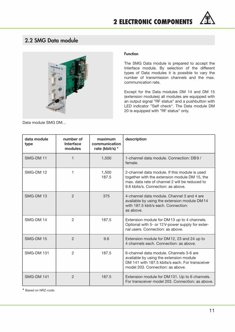
Data module SMG DM…
* Based on NRZ-code.
Function
The SMG Data module is prepared to accept theInterface module. By selection of the differenttypes of Data modules it is possible to vary thenumber of transmission channels and the max.communication rate.
Except for the Data modules DM 14 and DM 15(extension modules) all modules are equipped withan output signal ”RF status“ and a pushbutton withLED indicator ”Self check“. The Data module DM20 is equipped with ”RF status“ only.
data module number of maximum descriptiontype Interface communication
modules rate (kbit/s) *
SMG-DM 11 1 1,500 1-channel data module. Connection: DB9 /female.
SMG-DM 12 1 1,500 2-channel data module. If this module is used187.5 together with the extension module DM 15, the
max. data rate of channel 2 will be reduced to9.6 kbits/s. Connection: as above.
SMG-DM 13 2 375 4-channel data module. Channel 3 and 4 areavailable by using the extension module DM14 with 187.5 kbit/s each. Connection: as above.
SMG-DM 14 2 187.5 Extension module for DM13 up to 4 channels.Optional with 5- or 12V-power supply for exter-nal users. Connection: as above.
SMG-DM 15 2 9.6 Extension module for DM12, 23 and 24 up to4 channels each. Connection: as above.
SMG-DM 131 2 187.5 6-channel data module. Channels 3-6 areavailable by using the extension module DM 141 with 187.5 kbits/s each. For transceiver model 203. Connection: as above.
SMG-DM 141 2 187.5 Extension module for DM131. Up to 6 channels.For transceiver model 203. Connection: as above.

12
19 12 2 ELECTRONIC COMPONENTS
2.2 SMG Data module
... SMG - Data modules (continued)
data module number of maximum descriptiontype interface communication
modules rate (kbit/s) *
SMG-DM 20 1 10,000 Ethernet - applications IEEE 802.3 -standard. The module can accept forexample 2 optical Ethernet interfaces.
SMG-DM 21 1 10,000 Ethernet - applications IEEE 802.3 - standard.The module is equipped with a DB15 / femaleconnector for AUI cable to Ethernet-Transceiver.(For stationary Transceiver SMG-SES only).
SMG-DM 22 1 10,000 Ethernet - applications IEEE 802.3 - standard.The module is equipped with a DB15 / maleconnector for AUI cable to DTE. (For mobileTransceiver SMG-SEM only).
SMG-DM 23 2-channel data module- 5 MHz 1. Video input CCIR standard.
Coax BNC connector female 75 �1 187,5 ** 2. Data channel,
DB9 / female connector.
SMG-DM 24 2-channel data module- 5 MHz 1. Video output CCIR standard.
Coax BNC connector female 75 �1 187,5 ** 2. Data channel,
DB9 / female connector.
SMG- - - Emergency-Stop Module stop category 1,DM 14-SM 16 security level 3. DB9 / female connector to
VAHLE relay-box. (In combination to DM13/DM14 with 4/2 channel data-transmission only).
SMG- - - Emergency-Stop Module stop-category 1,DM 15-SM 16 security level 3. DB9 / female connector to
VAHLE relay-box. (In combination to DM 12with 2-channel data-transmission only).
** Based on Manchester-code
** Based on NRZ-code, higher communication rate on request

13
19 122 ELECTRONIC COMPONENTS
2.3 SMG Interface module
** Based on NRZ-code
** Based on Manchester-code
Interface Interface maximum descriptionmodule communicationtype rate (kbit/s) *
SMG-SM 1 TTY/20 mA 20 The module interfaces to: Sinec L1-Bus, PG-Interface, Interface Converter.Communication Processor.
SMG-SM 2 RS 232 C 20 The module interfaces to: Personal Computers,bar-code readers, scales, printers, or other devices that needs an RS 232 interface.
SMG-SM 3 RS 422 1,500 The module interface to: InterBus-S, point to point EN 50254 Vol. 2, measurement signal
transmission, and other 4-wire communication.
SMG-SM 4 RS 485 1,500 The module interfaces to: SINEC L1,adjustable Profibus EN 50170 Volume 2, Suconet-Bus,
and other 2-or 4-wire bus systems.
SMG-SM 5 RS 485 1,500 The module interfaces to: InterBus communicationenable and other devices that needs external half duplex
controlling.
SMG-SM 6 Allen-Bradley 230** The module interfaces to: Allen-Bradley DH+ andDH + / RIO adjustable RIO-communication networks. For use with DM13
module the max. communication rate is 115.2 kbit/s.
Function
The SMG Interface module is designed for adapti-on to the serial data of the external communicationsystem.
The modules are built as plug-in modules for theSMG Data modules DM... The communication rateis factory adjusted to customer specification.
Interface modul SMG SM …

14
19 12 2 ELECTRONIC COMPONENTS
2.3 SMG Interface module
… SMG Interface module (continued)
interface communication maximum descriptionmodule interface communicationtype rate (kbit/s)
SMG-SM 41 Allen Bradley 19.2 * The module interfaces to: DH 485-DataDH 485-Bus adjustable bus. The transmit direction is controlled by
an integrated repeater function.
SMG-SM 13 GE Genius 153.6 * The module interfaces to: General Electric- Data bus Standard / Extended
SMG-SM 7 Audio 0.3 - 3.4 kHz Full duplex interface for audio transmission(Intercom). Module requirements: 600 � /1 Vss.
SMG-SM 8 Ethernet 10,000 ** The module interfaces to: Ethernet applicationsIEEE 802,3. e.g. Siemens Industrial Ethernet. (The module is to be combinated with DataModule DM21 only).
SMG-SM 9 Ethernet 10,000 ** The module interfaces to: Ethernet applicationsIEEE 802,3 e.g. Siemens Industrial Ethernet.(The module is to be combinated with DataModule DM22 only).
SMG-SM 20 Ethernet 10,000 ** The module interfaces to: Ethernet applications acc. IEEE 802,3 e.g. Siemens Industrial Ethernetwith fiber optic connection. (The module is to be combinated with Data Module DM20 only)
SMG-SM 21 Ethernet 10,000 ** The module interfaces to: Ethernet applications(ITP RJ 45) acc. IEEE 802,3 e.g. Siemens Industrial Ethernet
with twisted pair connection. (The module isto be combinated with Data Module DM 20 only).
SMG-SM 10 Power Supply - The module provides a power supply of12 VDC 12 VDC with a nom. current of 100 mA.
With this module it is possible to supply powerto external users or SMG componentse.g. Antenna Switches.
** Based on NRZ-code
** Based on Manchester-code.
TM
15
19 122 ELECTRONIC COMPONENTS
2.4 SMG Antenna switch for crossover function
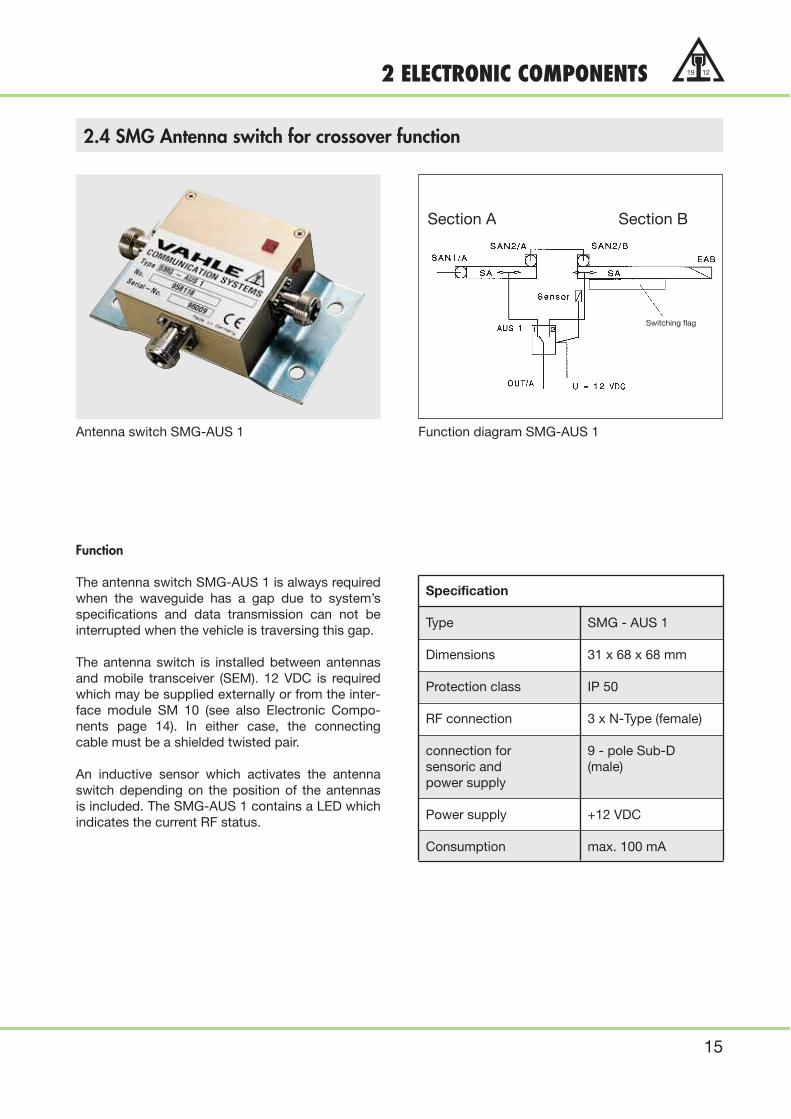
Antenna switch SMG-AUS 1 Function diagram SMG-AUS 1
Function
The antenna switch SMG-AUS 1 is always requiredwhen the waveguide has a gap due to system’sspecifications and data transmission can not beinterrupted when the vehicle is traversing this gap.
The antenna switch is installed between antennasand mobile transceiver (SEM). 12 VDC is requiredwhich may be supplied externally or from the inter-face module SM 10 (see also Electronic Compo-nents page 14). In either case, the connectingcable must be a shielded twisted pair.
An inductive sensor which activates the antennaswitch depending on the position of the antennasis included. The SMG-AUS 1 contains a LED whichindicates the current RF status.
Specification
Type SMG - AUS 1
Dimensions 31 x 68 x 68 mm
Protection class IP 50
RF connection 3 x N-Type (female)
connection for 9 - pole Sub-Dsensoric and (male)power supply
Power supply +12 VDC
Consumption max. 100 mA
Section A Section B
Switching flag

16
19 12 2 ELECTRONIC COMPONENTS
2.5 SMG Antenna switch for bypass function
Antenna switch SMG-AUS 2 Function diagram SMG-AUS 2
Function
When communicating with two or more vehicles ona SMG waveguide the antenna switch SMG-AUS 2automatically bridges the switched off SES / SEMtransceiver pair by disconnecting the power supply(e.g. when one vehicle is inoperative).
Specification
Type SMG - AUS 2
Dimensions 31 x 68 x 68 mm
Protection class IP 50
RF connection 4 x N-Type (female)
Connection for senso- 9 - pole Sub-Dric and power supply (male)
Power supply +12 VDC
Consumption max. 100 mA
Janus antenna
Vehicle 1 Vehicle 2

17
19 123 MECHANICAL COMPONENTS
3.1 SMG Waveguide
Function
The SMG waveguide, manufactured of extrudedaluminum, serves as the RF transmission medium.The specific shape of the waveguide is configuredfor the use with a frequency of approx. 2.4 GHz, itsdesign also assures minimum attenuation of signalpropagation. Also, the waveguide shape providesthe necessary interference shielding from the outsi-de and towards the outside.
Standard length of SMG waveguide section isL = 6 m. Shorter sections to conform with system’srequirements can be supplied (see order informa-tion chapter 5, page 32).
SMG waveguide curve sections for horizontal orvertical curves are also available, minimum radius900 mm.
Depending on environmental demands, three typesof surface treatment are available for the wave-guide sections:
SMG Waveguide section
Surface Treatment Designation Environmental Requirements
SMG Waveguide SMG/B No surface treatment to aluminum section, for indoor installationbright without environmental problems.
SMG Waveguide SMG/E Anodized aluminum waveguide for outdoor installations withanodized medium environmental conditions and at oceanside installations.
SMG Waveguide SMG/SB Epoxy coated aluminum waveguide for installation with severeepoxy coated environmental conditions, such as:
● Sulfuric acid
● Potassium hydroxide
● Deicing solution
● Decontamination solution
● Fuel
18
19 12 3 MECHANICAL COMPONENTS
3.2 RF Connection
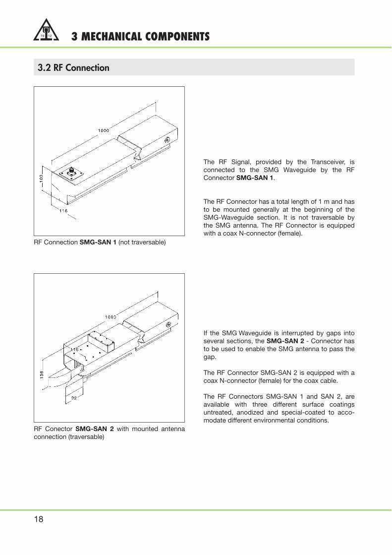
RF Connection SMG-SAN 1 (not traversable)
RF Conector SMG-SAN 2 with mounted antennaconnection (traversable)
The RF Signal, provided by the Transceiver, isconnected to the SMG Waveguide by the RFConnector SMG-SAN 1.
The RF Connector has a total length of 1 m and hasto be mounted generally at the beginning of theSMG-Waveguide section. It is not traversable bythe SMG antenna. The RF Connector is equippedwith a coax N-connector (female).
If the SMG Waveguide is interrupted by gaps intoseveral sections, the SMG-SAN 2 - Connector hasto be used to enable the SMG antenna to pass thegap.
The RF Connector SMG-SAN 2 is equipped with acoax N-connector (female) for the coax cable.
The RF Connectors SMG-SAN 1 and SAN 2, areavailable with three different surface coatingsuntreated, anodized and special-coated to acco-modate different environmental conditions.

19
19 123 MECHANICAL COMPONENTS
3.3 RF Termination
3.4 Joint Splice Clamp
3.5 Waveguide Anchor Bracket
RF Termination SMG-EAB
Joint Splice Clamp SMG-PV
Waveguide Anchor Bracket SMG-FL
To provide the necessary electrical termination ofthe SMG Waveguide, it is imperative to mount theRF Termination element SMG-EAB into the finalwaveguide section of the transmission link. Thisshould be done on site with the included mountingcomponents.
The Joint Splice Clamp SMG-PV provides a safemechanical and electrical connection of the SMGWaveguide sections.
It is available in galvanized and special-coatedversions.
The Splice Clamp includes installation hardware.
To provide the mechanical anchoring of the SMGWaveguide, the Anchor Bracket SMG-FL has to beinstalled in the middle of the Waveguide Section.
The Anchor Bracket ensures that the WaveguideSection can expand due to temperature influences.
The Anchor Bracket should also be used as agrounding connection. It is available in bright,anodized and special-coated versions.
Mounting hardware for easy installation is included.
20
19 12 3 MECHANICAL COMPONENTS
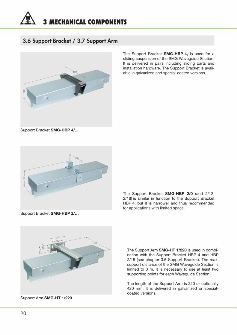
3.6 Support Bracket / 3.7 Support Arm
Support Bracket SMG-HBP 4/…
Support Bracket SMG-HBP 2/…
Support Arm SMG-HT 1/220
The Support Bracket SMG-HBP 4, is used for asliding suspension of the SMG Waveguide Section.It is delivered in pairs including sliding parts andinstallation hardware. The Support Bracket is avail-able in galvanized and special-coated versions.
The Support Bracket SMG-HBP 2/0 (and 2/12,2/18) is similar in function to the Support BracketHBP 4, but it is narrower and thus recommendedfor applications with limited space.
The Support Arm SMG-HT 1/220 is used in combi-nation with the Support Bracket HBP 4 and HBP2/18 (see chapter 3.6 Support Bracket). The max.support distance of the SMG Waveguide Section islimited to 3 m. It is necessary to use at least twosupporting points for each Waveguide Section.
The length of the Support Arm is 220 or optionally420 mm. It is delivered in galvanized or special-coated versions.
140
192
140
126
80220
110
2050
20
11

21
19 123 MECHANICAL COMPONENTS
3.7 Support Arm
Support Arm SMG-HT 2/220
The Support Arm SMG-HT 2/220 is similar in fuc-tion to the Support Arm type HT 1/220. It is equip-ped with a vertical flange for mounting.
The length of the support arm is 220 or optionally420 mm. It is delivered in galvanized or specialcoated version.
220
40
17
87
20
11
58
SMG in action for Ethernet data transmission for coking machinery

22
19 12 3 MECHANICAL COMPONENTS
3.8 Antenna
Antenna SMG-SAE-XY-3
The Antenna SMG-SAE- (RAE, JAE) -XY-3 con-sists of the antenna element and the antenna sup-port arm.
With this device, it is possible to compensate late-ral (x-axis) and vertical (y-axis) movements of thevehicle. The maximum permissible tolerances areshown in the lower chart.
The antenna with support arm is factory assem-bled. The flange has two elongated holes for easyadjustment and installation to the vehicle.
Description Type Permissible Tolerances (mm)
Antenna Model x - Axis Y - Axis
Standard- 01 SMG-SAE-XY-3 ± 20 +5 –1002 ± 40 +5 –10
Directional- 01 SMG-RAE-XY-3 ± 20 +5 –1002 ± 40 +5 –10
Janus- 01 SMG-JAE-XY-3 ± 20 +5 –1002 ± 40 +5 –10
Chart of the max. permissible tolerances
Antennas for larger permissible tolerances on request.

23
19 123 MECHANICAL COMPONENTS
3.9 Mobile Antennas (Spare parts only)
3.10 Special Antenna assembly
The standard antenna SMG-SA is used for basicSMG data transmission installations such as bus orpoint-to-point connection with a mobile unit. Twostandard antennas, installed at a given distancefrom each other and connected with an antennaswitch SMG-AUS 1, form a double antenna to brid-ge gaps in the Waveguide caused by system’srequirements (see chapter 2.4, page 15, SMGantenna switch).
The antenna has a flexible, 0.6 m long RF connect-ing cable with N-plug.
The directional antenna SMG-RA, for instance, isused when there are two mobile participants on thewaveguide and the RF connection is on each endof the waveguide (see also system’s diagram 2,page 7).
Also, the directional antenna may be utilized withdouble transceivers (SES/SEM) and with two ormore participants on the waveguide (similar tosystem’s diagram 3, page 8).
The antenna has a flexible, 0.6 m long RF connect-ing cable with N-plug.
Antenna assembly SMG-RAE-XY 6 for largecranes, coking machinery and other material hand-ling systems with tolerances of ± 150 mm in X-Y-direction.
Standard antenna SMG-SA
Directional antenna SMG-RA
Directional antenna SMG-RAE-XY 6

24
19 12 3 MECHANICAL COMPONENTS
3.11 RF cables with Accessories
The RF Connecting cable SMG-HF is required toconnect the stationary transceiver (SMG-SES) withthe SMG Waveguide or to connect the transceiverand the antennas with the antenna switch SMG-AUS 1 and SMG-AUS 2.
SMG-HF is a specially made cable with lowattenuation, minimum bending radius of 100 mmand can only be used for fixed (non-flexing) instal-lation. The cable has an OD of 10 mm with factoryinstalled N-type connectors at each end, availablein lengths of 1 m, 2 m, 3 m, 4 m and 5 m.
If a RF Connecting cable has to be lengthened anadditional connecting cable can be added with thestraight N-type connector SMG-HF-N-VBB.
The N-type angle connector SMG-HF-N-WVenables a space saving cable connection arrange-ment to the transceiver. The connector is tightenedwith a hexnut, use a torque setting of 0.7 to 1.1Nm. If the protective cover IP 53 is installed with atransceiver, an angle connector is included with theshipment and it must be used.
If axial transmission is desired a rotating couplerSMG-HF-DK can be used in place of the wave-guide.
The SMG-HF-DK has two N-type sockets so thetransceiver can be directly connected with ourstandard RF cable SMG-HF.
Sufficient equalization of potentiality between therotating and the fixed components must be as-sured.
HF Connecting cable SMG-HF
N-type Connector straight, and right angle
RF Rotating coupler SMG-HF-DK

25
19 124 CONFIGURATION SUPPORT
4.1 Constructional design of the SMG waveguide
Installation of SMG Waveguide
SMG Waveguide is installed parallel with thevehicle track, slot opening pointing downward. Thewaveguide is supported with sliding hangerbracket on 3 m centers and may be installedtogether with the conductor system.
Standard length for a SMG Waveguide section is 6m. Sections are joined with bolted joint spliceclamps to make the required system’s length. Becertain to have at least 200 mm clearence betweenjoint splice clamp and hanger bracket.
The support hanger permits the waveguide to slidefreely during thermal expansion or contraction.Systems up to 200 m long may be anchoredanywhere along the system with the includedanchor bracket so that controlled expansion/con-traction is assured.
Installations exceeding 200 m and having largetemperature variations must be anchored at thecenter of the system. The very last sliding hangerbracket should be positioned approx. 500 mm fromthe end of the system.
SMG Waveguide components
RF Connection and termination
The waveguide section SMG-SAN 1 must beinstalled at one of the ends of the waveguide. Herethe connection is made to the stationary trans-ceiver SES with the use of the special RF Connect-ing cable SMG-HF.
RF Termination SMG-EAB is installed at the otherend of the waveguide unless a SAN-SAN 1connection is also required as shown on system’sdiagram 2, page 7.

26
19 12 4 CONFIGURATION SUPPORT
4.1 Constructional Design of the SMG Waveguide
Typical arrangement of the SMG Waveguide and Conductor Rail
Typical arrangement of the SMG Antenna and unipole insulated conductor U 35
128 200 90 90 90
224
203
225
27
19 124 CONFIGURATION SUPPORT
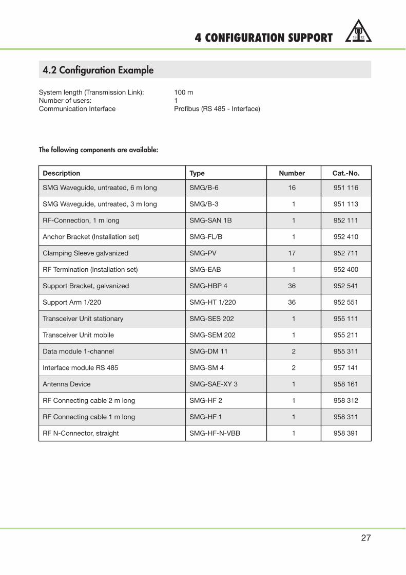
4.2 Configuration Example
System length (Transmission Link): 100 mNumber of users: 1Communication Interface Profibus (RS 485 - Interface)
The following components are available:
Description Type Number Cat.-No.
SMG Waveguide, untreated, 6 m long SMG/B-6 16 951 116
SMG Waveguide, untreated, 3 m long SMG/B-3 1 951 113
RF-Connection, 1 m long SMG-SAN 1B 1 952 111
Anchor Bracket (Installation set) SMG-FL/B 1 952 410
Clamping Sleeve galvanized SMG-PV 17 952 711
RF Termination (Installation set) SMG-EAB 1 952 400
Support Bracket, galvanized SMG-HBP 4 36 952 541
Support Arm 1/220 SMG-HT 1/220 36 952 551
Transceiver Unit stationary SMG-SES 202 1 955 111
Transceiver Unit mobile SMG-SEM 202 1 955 211
Data module 1-channel SMG-DM 11 2 955 311
Interface module RS 485 SMG-SM 4 2 957 141
Antenna Device SMG-SAE-XY 3 1 958 161
RF Connecting cable 2 m long SMG-HF 2 1 958 312
RF Connecting cable 1 m long SMG-HF 1 1 958 311
RF N-Connector, straight SMG-HF-N-VBB 1 958 391

28
19 12 4 CONFIGURATION SUPPORT
4.2 Configuration example
Please consider the following aspects when designing a system:
● Position the stationary transceiver SES as closely as possible to the RF Connection SMG-SAN 1 and themobile transceiver SEM as closely as possible to the antenna (SMG-SAE-XY3) to keep the RF connectingcable as short as possible (5 m max. length).
● The antenna (SMG-SAE-XY3) used with the example above permits maximum X-axis tolerance of +/- 20mm and maximum Y-axis tolerance of + 5 mm / - 10 mm. This tolerance should be adhered to if at allpossible to assure non-contact movement of the antenna. Select antenna type 02 (see page 22) whengreater XY-axis tolerance is excepted.
● The for the example selected hanger brackets require a defined available space to be installed. If the avail-able space is limited, special hanger brackets are available (please see page 20 and 21). It is also possibleto install the waveguide on the same bracket which supports the conductor system (see page 26).
● If frequency inverters are used please follow the instructions of the manufacturer with reference to interfe-rence elimination, cable support and cable shielding. Data cables and power cables must be separatedby at least 100 mm.
System´s diagram for the configuration example

29
19 124 CONFIGURATION SUPPORT
4.3 Questionnaire
For a detailed quotation, please complete this page and send it by fax. For special applications whichcannot be covered by this questionnaire, please contact our Head Office in Germany or our local office inyour area.
PAUL VAHLE GmbH & Co. KG
D-59172 Kamen
Fax: 0 23 07/ 70 44 44
e-mail: [email protected]
Internet: www.vahle.de
1. Type of vehicle or mobile device?
a) crane � b) material handling � c) AS/RS warehouse �
d) monorails �
e) others ___________________________________________________________________________________
2. Length of runway (s): ______ m
3. Number of vehicles on runway: ______
4. Type of communication interface:
______________________________________________________________________________________________
______________________________________________________________________________________________
5. Transmission of E-Stop needed? yes � no �
6. Max. needed data rate ______ kbit/s
7. Ambient temperature: ______°C min. ______°C max.
8. What environmental conditions have to be expected?
a) Outdoor system � b) Indoor system � c) Dust � d) Electromagnetic influence �
e) Acid � f) Humidity � g) Oils �
h) Others: __________________________________________________________________________________
9. Additional _________________________________________________________________________________Notes:
_________________________________________________________________________________
Address: _______________________________
Contact Person: _______________________________
Tel./Fax: ______________________________________
Date: _______________________________________
30
19 12 5 TECHNICAL DESCRIPTION FOR ORDERING
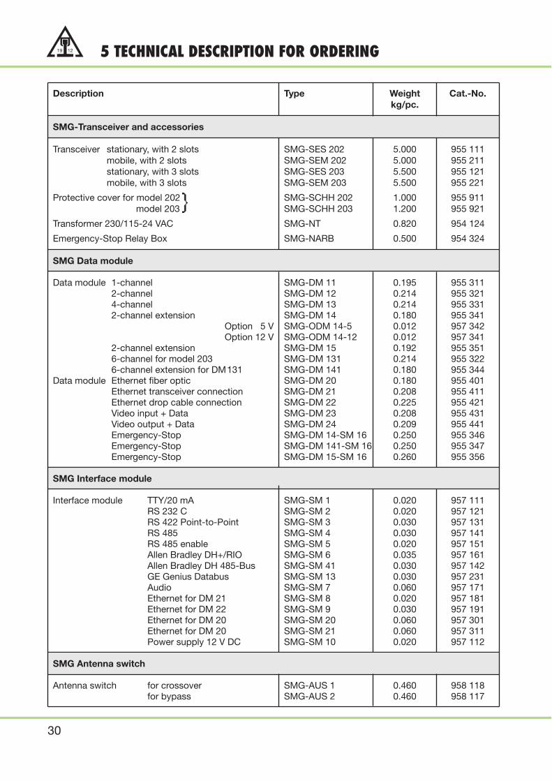
Description Type Weight Cat.-No.kg/pc.
SMG-Transceiver and accessories
Transceiver stationary, with 2 slots SMG-SES 202 5.000 955 111mobile, with 2 slots SMG-SEM 202 5.000 955 211stationary, with 3 slots SMG-SES 203 5.500 955 121mobile, with 3 slots SMG-SEM 203 5.500 955 221
Protective cover for model 202 SMG-SCHH 202 1.000 955 911model 203 SMG-SCHH 203 1.200 955 921
Transformer 230/115-24 VAC SMG-NT 0.820 954 124
Emergency-Stop Relay Box SMG-NARB 0.500 954 324
SMG Data module
Data module 1-channel SMG-DM 11 0.195 955 3112-channel SMG-DM 12 0.214 955 3214-channel SMG-DM 13 0.214 955 3312-channel extension SMG-DM 14 0.180 955 341
Option 5 V SMG-ODM 14-5 0.012 957 342Option 12 V SMG-ODM 14-12 0.012 957 341
2-channel extension SMG-DM 15 0.192 955 3516-channel for model 203 SMG-DM 131 0.214 955 3226-channel extension for DM131 SMG-DM 141 0.180 955 344
Data module Ethernet fiber optic SMG-DM 20 0.180 955 401Ethernet transceiver connection SMG-DM 21 0.208 955 411Ethernet drop cable connection SMG-DM 22 0.225 955 421Video input + Data SMG-DM 23 0.208 955 431Video output + Data SMG-DM 24 0.209 955 441Emergency-Stop SMG-DM 14-SM 16 0.250 955 346Emergency-Stop SMG-DM 141-SM 16 0.250 955 347Emergency-Stop SMG-DM 15-SM 16 0.260 955 356
SMG Interface module
Interface module TTY/20 mA SMG-SM 1 0.020 957 111RS 232 C SMG-SM 2 0.020 957 121RS 422 Point-to-Point SMG-SM 3 0.030 957 131RS 485 SMG-SM 4 0.030 957 141RS 485 enable SMG-SM 5 0.020 957 151Allen Bradley DH+/RIO SMG-SM 6 0.035 957 161Allen Bradley DH 485-Bus SMG-SM 41 0.030 957 142GE Genius Databus SMG-SM 13 0.030 957 231Audio SMG-SM 7 0.060 957 171Ethernet for DM 21 SMG-SM 8 0.020 957 181Ethernet for DM 22 SMG-SM 9 0.030 957 191Ethernet for DM 20 SMG-SM 20 0.060 957 301Ethernet for DM 20 SMG-SM 21 0.060 957 311Power supply 12 V DC SMG-SM 10 0.020 957 112
SMG Antenna switch
Antenna switch for crossover SMG-AUS 1 0.460 958 118for bypass SMG-AUS 2 0.460 958 117

31
19 125 TECHNICAL DESCRIPTION FOR ORDERING
Description Type Weight Cat.-No.kg/pc.
Antenna
Standard antenna mit 0.6 m cable, model 01 SMG-SAE-XY-3 1.630 958 161model 02 SMG-SAE-XY-3 1.635 958 161-2
Directional antenna, 0.6 m cable model 01 SMG-RAE-XY-3 2.000 958 162model 02 SMG-RAE-XY-3 2.005 958 162-2
Janus antenna, 0.6 m cable model 01 SMG-JAE-XY-3 2.180 958 163model 02 SMG-JAE-XY-3 2.185 958 163-2
Antenna (for spare only)
Standard antenna, 0.6 m cable SMG-SA 0.160 958 111Directional antenna, 0.6 m cable SMG-RA 0.530 958 112Janus antenna, 0.6 m cable SMG-JA 0.710 958 113
RF Cable and Accessories
RF cable with N-connector, 1 m SMG-HF-1 0.225 958 3112 m SMG-HF-2 0.450 958 3123 m SMG-HF-3 0.675 958 3134 m SMG-HF-4 0.900 958 3145 m SMG-HF-5 1.125 958 315
RF N-connector, straight with cable clamp SMG-HF-N-VBB 0.034 958 394RF N-connector, right angle SMG-HF-N-WV 0.080 958 390RF Rotary coupler SMG-HF-DK 1.000 958 395
RF Connectors and Accessories
SMG-RF connector, untreated, 1 m SMG-SAN 1 B 1.100 952 111as before, but traversable SMG-SAN 2 B 1.200 952 121SMG-RF connector, anodized, 1 m SMG-SAN 1 E 1.100 952 131as before, but traversable SMG-SAN 2 E 1.200 952 141SMG-RF connector, special coated, 1 m SMG-SAN 1 SB 1.200 952 151as before, but traversable SMG-SAN 2 SB 1.300 952 161
SMG antenna guiding (installation kit) SMG-EK 0.250 952 405
RF Termination
SMG-RF Termination (installation kit) SMG-EAB 0.150 952 400

32
19 12 5 TECHNICAL DESCRIPTION FOR ORDERING
Description Type Weight Cat.-No.kg/pc.
SMG Waveguide untreated
SMG Waveguide 1 m SMG/B-1 2.500 951 1112 m SMG/B-2 5.000 951 1123 m SMG/B-3 7.500 951 1134 m SMG/B-4 10.000 951 1145 m SMG/B-5 12.500 951 1156 m SMG/B-6 15.000 951 116
SMG Waveguide anodized
SMG Waveguide 1 m SMG/E-1 2.500 951 1312 m SMG/E-2 5.000 951 1323 m SMG/E-3 7.500 951 1334 m SMG/E-4 10.000 951 1345 m SMG/E-5 12.500 951 1356 m SMG/E-6 15.000 951 136
SMG Waveguide epoxy coated
SMG Waveguide 1 m SMG/SB-1 2.600 951 1512 m SMG/SB-2 5.200 951 1523 m SMG/SB-3 7.800 951 1534 m SMG/SB-4 10.400 951 1545 m SMG/SB-5 13.000 951 1556 m SMG/SB-6 15.600 951 156
SMG Joint Splice Clamp
SMG Joint Splice Clamp galvanized SMG-PV 1.000 952 711special-coated SMG-PV/SB 1.100 952 751
SMG Support Bracket
pair of support brackets SMG-HBP 4 0.250 952 541

33
19 125 TECHNICAL DESCRIPTION FOR ORDERING
Description Type Weight Cat.-No.kg/pc.
SMG Support Bracket
pair of support brackets 2/0 galvanized SMG-HBP 2/0 0.400 952 521special-coated SMG-HBP 2/0 SB 0.400 952 522
2/12 galvanized SMG-HBP 2/12 0.400 952 523 special-coated SMG-HBP 2/12 SB 0.400 952 524
2/18 galvanized SMG-HBP 2/18 0.400 952 525 special-coated SMG-HBP 2/18 SB 0.400 952 526
SMG Support Arm
support arm 1/220 galvanized SMG-HT 1/220 0.500 952 551 special-coated SMG-HT 1/220 SB 0.550 952 552
1/420 galvanized SMG-HT 1/420 0.850 952 651 special-coated SMG-HT 1/420 SB 0.950 952 652
2/220 galvanized SMG-HT 2/220 0.500 952 553 special-coated SMG-HT 2/220 SB 0.550 952 554
SMG Anchor Bracket
SMG anchor bracket, installation kit untreated SMG-FL/B 0.200 952 410 anodized SMG-FL/E 0.200 952 430 special-coated SMG-FL/SB 0.200 952 450
Antenna support arm assembly for a large crane application.

34
19 12 6 CERTIFICATION
PTB Text Certificate

35
19 126 CERTIFICATION
TÜV Certificate
FCC Certificate
In accordance with our company’s policy of continued improvement, we reserve the right to amend specifications and details at any time.
Catalog No. 9e/E 2002
PAUL VAHLE GMBH & CO. KG · D 59172 KAMEN/GERMANY · TEL. 0 23 07/ 70 40Internet: www.vahle.de · e-mail: postmaster @ vahle.de · FAX 0 23 07/ 70 44 44
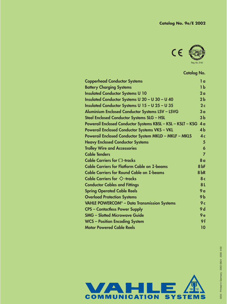
Catalog No.
Copperhead Conductor Systems 1 aBattery Charging Systems 1 bInsulated Conductor Systems U 10 2 aInsulated Conductor Systems U 20 – U 30 – U 40 2 bInsulated Conductor Systems U 15 – U 25 – U 35 2 cAluminium Enclosed Conductor Systems LSV – LSVG 3 aSteel Enclosed Conductor Systems SLG – HSL 3 bPowerail Enclosed Conductor Systems KBSL – KSL – KSLT – KSG 4 aPowerail Enclosed Conductor Systems VKS – VKL 4 bPowerail Enclosed Conductor System MKLD – MKLF – MKLS 4 cHeavy Enclosed Conductor Systems 5Trolley Wire and Accessories 6Cable Tenders 7Cable Carriers for -tracks 8 aCable Carriers for Flatform Cable on -beams 8 bFCable Carriers for Round Cable on -beams 8 bRCable Carriers for -tracks 8 cConductor Cables and Fittings 8 LSpring Operated Cable Reels 9 aOverload Protection Systems 9 bVAHLE POWERCOM® – Data Transmission Systems 9 cCPS – Contactless Power Supply 9 dSMG – Slotted Microwave Guide 9 eWCS – Position Encoding System 9 fMotor Powered Cable Reels 10
Reg. No. 3140
0204
· P
rinte
d in
Ger
man
y · 2
002-
0824
· 20
00· 4
/02