smc100cc - carnegie institution for...
TRANSCRIPT
Single-Axis Motion Controller/Driverfor DC Motors
SMC100CC
USER’S MANUAL
FIRMWARE V2.0


iii EDH0206En1022 — 09/06
SMC100CC Single-Axis Motion Controller/Driver for DC Motors
Table of Contents
Warranty..................................................................................................................v
EU Declaration of Conformity..............................................................................vi
Preface ...............................................................................................................vii
Confidentiality & Proprietary Rights.............................................................vii
Sales, Tech Support & Service ......................................................................viii
Service Information ........................................................................................viii
Newport Corporation RMA Procedures ......................................................viii
Packaging.........................................................................................................viii
1.0 — Safety Precautions ....................................................................1
1.1 Definitions and Symbols...........................................................................1
General Warning or Caution ....................................................................1
Electric Shock ............................................................................................1
European Union CE Mark .........................................................................1
1.2 Warnings and Cautions ............................................................................2
General Warnings and Cautions..............................................................2
2.0 — System Overview ......................................................................3
2.1 General Description ..................................................................................3
2.2 Part Numbers.............................................................................................3
2.3 SMC100CC ..................................................................................................4
Contents of Delivery .................................................................................4
Specifications.............................................................................................5
Dimensions.................................................................................................5
2.4 SMC-RC .......................................................................................................6
Specifications.............................................................................................6
Dimensions.................................................................................................6
2.5 SMC-PS80....................................................................................................7
Specifications.............................................................................................7
Dimensions.................................................................................................7
2.6 System Environmental Specifications ....................................................7
2.7 Connector Identification ..........................................................................8
2.8 Serial Communication Settings ...............................................................8
3.0 — Getting Started ...........................................................................9
3.1 SMC100CC Software Installation .............................................................9
3.2 Communication Settings ..........................................................................9
RS-232-C Communication (Using SMC-232 Cable).................................9
USB Communication (Using SMC-USB Interface) ..................................9
3.3 Communication to a Single SMC100CC ................................................10

EDH0206En1022 — 09/06 iv
SMC100CC Single-Axis Motion Controller/Driver for DC Motors
3.4 Communication to Several SMC100CC .................................................12
Controller Address Setting.....................................................................12
Building the System ................................................................................14
Enable all controllers..............................................................................15
Configuring the Controller .....................................................................17
4.0 — SMC100CC with SMC-RC Keypad ....................................18
5.0 — Programming ............................................................................20
5.1 State Diagram...........................................................................................20
5.2 Initialization .............................................................................................21
5.3 Command Syntax ....................................................................................22
5.4 Command Execution Time.....................................................................22
5.5 Command Set...........................................................................................23
6.0 — Connector Pinout ....................................................................73
6.1 DC IN and DC OUT (Female Ø 2.1 x Ø 5.5 x 11 mm)............................73
6.2 RS-232-C (Male Sub-D9) ..........................................................................73
6.3 RS-485 IN and RS-485 OUT (Female RJ11-6/6).....................................73
6.4 Keypad (Female RJ9-4/4)........................................................................73
6.5 GPIO (Female Sub-D15)...........................................................................74
6.6 Motor (Female Sub-D25).........................................................................74
7.0 — Backlash Compensation.......................................................75
8.0 — ESP Stages ...................................................................................75
9.0 — PID Control Loop Structure ...............................................76
10.0 — Maintenance and Service ...................................................77
10.1 Enclosure Cleaning .................................................................................77
10.2 Obtaining Service ....................................................................................77
Service Form .........................................................................................................78

v EDH0206En1022 — 09/06
SMC100CC Single-Axis Motion Controller/Driver for DC Motors
Warranty
Newport Corporation warrants that this product will be free from defects inmaterial and workmanship and will comply with Newport’s published spec-ifications at the time of sale for a period of one year from date of shipment.If found to be defective during the warranty period, the product will eitherbe repaired or replaced at Newport's option.
To exercise this warranty, write or call your local Newport office or repre-sentative, or contact Newport headquarters in Irvine, California. You willbe given prompt assistance and return instructions. Send the product,freight prepaid, to the indicated service facility. Repairs will be made andthe instrument returned freight prepaid. Repaired products are warrantedfor the remainder of the original warranty period or 90 days, whicheveroccurs last.
Limitation of Warranty
The above warranties do not apply to products which have been repairedor modified without Newport’s written approval, or products subjected tounusual physical, thermal or electrical stress, improper installation, mis-use, abuse, accident or negligence in use, storage, transportation or han-dling.
THIS WARRANTY IS IN LIEU OF ALL OTHER WARRANTIES, EXPRESSED ORIMPLIED, INCLUDING ANY IMPLIED WARRANTY OF MERCHANTABILITY ORFITNESS FOR A PARTICULAR USE. NEWPORT CORPORATION SHALL NOTBE LIABLE FOR ANY INDIRECT, SPECIAL, OR CONSEQUENTIAL DAMAGESRESULTING FROM THE PURCHASE OR USE OF ITS PRODUCTS.
First printing 2005
Copyright 2005 by Newport Corporation, Irvine, CA. All rights reserved. Nopart of this manual may be reproduced or copied without the prior writtenapproval of Newport Corporation. This manual is provided for informationonly, and product specifications are subject to change without notice. Anychange will be reflected in future printings.
EDH0206En1022 — 09/06 vi
SMC100CC Single-Axis Motion Controller/Driver for DC Motors
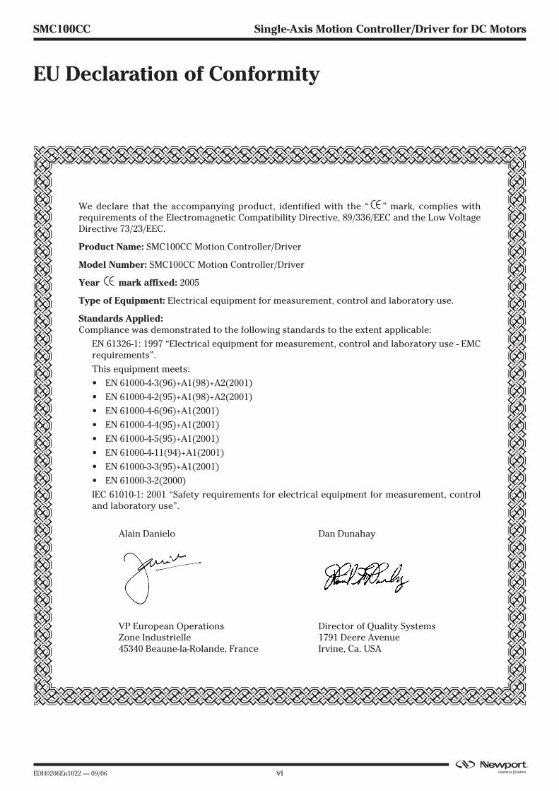
EU Declaration of Conformity
We declare that the accompanying product, identified with the “ ” mark, complies withrequirements of the Electromagnetic Compatibility Directive, 89/336/EEC and the Low VoltageDirective 73/23/EEC.
Product Name: SMC100CC Motion Controller/Driver
Model Number: SMC100CC Motion Controller/Driver
Year mark affixed: 2005
Type of Equipment: Electrical equipment for measurement, control and laboratory use.
Standards Applied:Compliance was demonstrated to the following standards to the extent applicable:
EN 61326-1: 1997 “Electrical equipment for measurement, control and laboratory use - EMCrequirements”.
This equipment meets:
• EN 61000-4-3(96)+A1(98)+A2(2001)
• EN 61000-4-2(95)+A1(98)+A2(2001)
• EN 61000-4-6(96)+A1(2001)
• EN 61000-4-4(95)+A1(2001)
• EN 61000-4-5(95)+A1(2001)
• EN 61000-4-11(94)+A1(2001)
• EN 61000-3-3(95)+A1(2001)
• EN 61000-3-2(2000)
IEC 61010-1: 2001 “Safety requirements for electrical equipment for measurement, controland laboratory use”.
Alain Danielo Dan Dunahay
VP European Operations Director of Quality SystemsZone Industrielle 1791 Deere Avenue45340 Beaune-la-Rolande, France Irvine, Ca. USA

vii EDH0206En1022 — 09/06
SMC100CC Single-Axis Motion Controller/Driver for DC Motors
Preface
Confidentiality & Proprietary Rights
Reservation of Title
The Newport Programs and all materials furnished or produced in connec-tion with them ("Related Materials") contain trade secrets of Newport andare for use only in the manner expressly permitted. Newport claims andreserves all rights and benefits afforded under law in the Programs provid-ed by Newport Corporation.
Newport shall retain full ownership of Intellectual Property Rights in and toall development, process, align or assembly technologies developed andother derivative work that may be developed by Newport. Customer shallnot challenge, or cause any third party to challenge, the rights of Newport.
Preservation of Secrecy and Confidentiality and Restrictions to Access
Customer shall protect the Newport Programs and Related Materials astrade secrets of Newport, and shall devote its best efforts to ensure that allits personnel protect the Newport Programs as trade secrets of NewportCorporation. Customer shall not at any time disclose Newport's tradesecrets to any other person, firm, organization, or employee that does notneed (consistent with Customer's right of use hereunder) to obtain accessto the Newport Programs and Related Materials. These restrictions shallnot apply to information (1) generally known to the public or obtainablefrom public sources; (2) readily apparent from the keyboard operations,visual display, or output reports of the Programs; (3) previously in the pos-session of Customer or subsequently developed or acquired withoutreliance on the Newport Programs; or (4) approved by Newport for releasewithout restriction.
EDH0206En1022 — 09/06 viii
SMC100CC Single-Axis Motion Controller/Driver for DC Motors
Sales, Tech Support & Service
Service Information
The user should not attempt any maintenance or service of the SMC100CCController/Driver and its accessories beyond the procedures outlined inthis manual. Any problem that cannot be resolved should be referred toNewport Corporation. When calling Newport regarding a problem, pleaseprovide the Tech Support representative with the following information:
• Your contact information.
• System serial number or original order number.
• Description of problem.
• Environment in which the system is used.
• State of the system before the problem.
• Frequency and repeatability of problem.
• Can the product continue to operate with this problem?
• Can you identify anything that may have caused the problem?
Newport Corporation RMA Procedures
Any SMC100CC Controller/Driver being returned to Newport must havebeen assigned an RMA number by Newport. Assignment of the RMArequires the item serial number.
Packaging
SMC100CC Controller/Driver being returned under an RMA must be secure-ly packaged for shipment. If possible, reuse the original factory packaging.
Europe
MICRO-CONTROLE
1, rue Jules Guesde – Bât. BZI Bois de l’Épine – BP18991006 Evry CedexFrance
Sales & Technical Support
+33 (0)1.60.91.68.68
e-mail: [email protected]
Service & Returns
+33 (0)2.38.40.51.55
North America & Asia
Newport Corporation
1791 Deere Ave.Irvine, CA 92606, USA
Sales
(949) 253-1461 or (800) 222-6440 x31461
e-mail: [email protected]
Technical Support
(949) 253-1406 or (800) 222-6440 x31406
e-mail: [email protected]
Service, RMAs & Returns
(949) 253-1694 or (800) 222-6440 x31694
e-mail: [email protected]

1 EDH0206En1022 — 09/06
SMC100CC Single-Axis Motion Controller/Driver for DC Motors
SMC100CCSingle-Axis Motion Controller/Driver for DC Motors
1.0 Safety Precautions
1.1 Definitions and Symbols
The following terms and symbols are used in this documentation and alsoappear on the SMC100CC Controller/Driver where safety-related issuesoccur.
1.1.1 General Warning or Caution
Figure 1: General Warning or Caution Symbol.
The Exclamation Symbol in figure 1 may appear in Warning and Cautiontables in this document. This symbol designates an area where personalinjury or damage to the equipment is possible.
1.1.2 Electric Shock
Figure 2: Electrical Shock Symbol.
The Electrical Shock Symbol in Figure 2 may appear on labels affixed to theSMC100CC Controller/Driver. This symbol indicates a hazard arising fromdangerous voltage. Any mishandling could result in irreparable damage tothe equipment, in personal injury, or death.
1.1.3 European Union CE Mark
Figure 3: CE Mark.
The presence of the CE Mark on Newport Corporation equipment meansthat it has been designed, tested and certified as complying with all applic-able European Union (CE) regulations and recommendations.
EDH0206En1022 — 09/06 2
SMC100CC Single-Axis Motion Controller/Driver for DC Motors
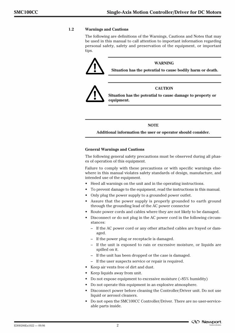
1.2 Warnings and Cautions
The following are definitions of the Warnings, Cautions and Notes that maybe used in this manual to call attention to important information regardingpersonal safety, safety and preservation of the equipment, or importanttips.
WARNING
Situation has the potential to cause bodily harm or death.
CAUTION
Situation has the potential to cause damage to property orequipment.
NOTE
Additional information the user or operator should consider.
1.2.1 General Warnings and Cautions
The following general safety precautions must be observed during all phas-es of operation of this equipment.
Failure to comply with these precautions or with specific warnings else-where in this manual violates safety standards of design, manufacture, andintended use of the equipment.
• Heed all warnings on the unit and in the operating instructions.
• To prevent damage to the equipment, read the instructions in this manual.
• Only plug the power supply to a grounded power outlet.
• Assure that the power supply is properly grounded to earth groundthrough the grounding lead of the AC power connector
• Route power cords and cables where they are not likely to be damaged.
• Disconnect or do not plug in the AC power cord in the following circum-stances:
– If the AC power cord or any other attached cables are frayed or dam-aged.
– If the power plug or receptacle is damaged.
– If the unit is exposed to rain or excessive moisture, or liquids arespilled on it.
– If the unit has been dropped or the case is damaged.
– If the user suspects service or repair is required.
• Keep air vents free of dirt and dust.
• Keep liquids away from unit.
• Do not expose equipment to excessive moisture (>85% humidity)
• Do not operate this equipment in an explosive atmosphere.
• Disconnect power before cleaning the Controller/Driver unit. Do not useliquid or aerosol cleaners.
• Do not open the SMC100CC Controller/Driver. There are no user-service-able parts inside.

3 EDH0206En1022 — 09/06
SMC100CC Single-Axis Motion Controller/Driver for DC Motors
• Return equipment to Newport Corporation for service and repair.
• Dangerous voltages associated with the 100-240 VAC power supply arepresent inside the power supply. To avoid injury, do not touch exposedconnections or components while power is on.
• Follow precautions for static-sensitive devices when handling electroniccircuits.
2.0 System Overview
2.1 General Description
The SMC100CC is a single axis motion controller/driver for DC servomotors up to 48 VDC at 1.5 A rms. It provides a very compact and low-costsolution for driving a variety of Newport and other manufacturers motor-ized stages from a PC or from the optional SMC-RC remote control.
Communication with the SMC100CC is achieved via a RS-232-C, or from aUSB port using the external adapter SMC-USB (requires Windows™ operat-ing system). A Windows based software supports all configurations andenables basic motion. Advanced application programming is simplified byan ASCII command interface and a set of two letter mnemonic commands.
When used with Newport ESP enhanced positioners, the SMC100CC willdetect the connected product automatically and provides easy configura-tion using the supplied Windows-based utility software. This exclusiveNewport feature reduces configuration time and provides the best protec-tion of your equipment from any accidental damages.
Up to 31 controllers can be networked through the internal RS-485 commu-nication link. This internal multi-drop full-duplex serial link simplifies com-munication to several units, without the need for sending “address selec-tion commands”. This results in enhanced multi-axes management withimproved program readability and faster communication compared toalternative systems based on a RS-232-C chain. The typical execution timefor a tell position command is only about 10 ms for the first controller andonly about 16 ms for the other controllers. The SMC100CC also featuresadvanced “multi-axes” commands such as “Stop all” or “start a motion ofall axes” and performs at a 57,600 baud rate communication speed.Furthermore, for an efficient process control, the SMC100CC features dedi-cated digital outputs for "In Motion" and for "Not referenced".
2.2 Part Numbers
Product Description
SMC100CC Single-axis motion controller/driver for DC servo motors.Includes 0.2 m long power and RS-485 cable.
SMC-RC Remote control keypad for SMC100CC.
SMC-PS80 80 W power supply for SMC100CC.
SMC-232 RS-232-C cable, 3 m length (DB9F to DB9F).
SMC-USB USB interface, Includes one USB to COM port adapterand one RS-232-C cable.Requires Windows™ operating system.
SMC-CB1 1 m RS-485 cable (only required when RS-485 cable sup-plied with SMC100CC is too short).
SMC-CB3 3 m RS-485 cable (only required when RS-485 cable sup-plied with SMC100CC is too short).
EDH0206En1022 — 09/06 4
SMC100CC Single-Axis Motion Controller/Driver for DC Motors
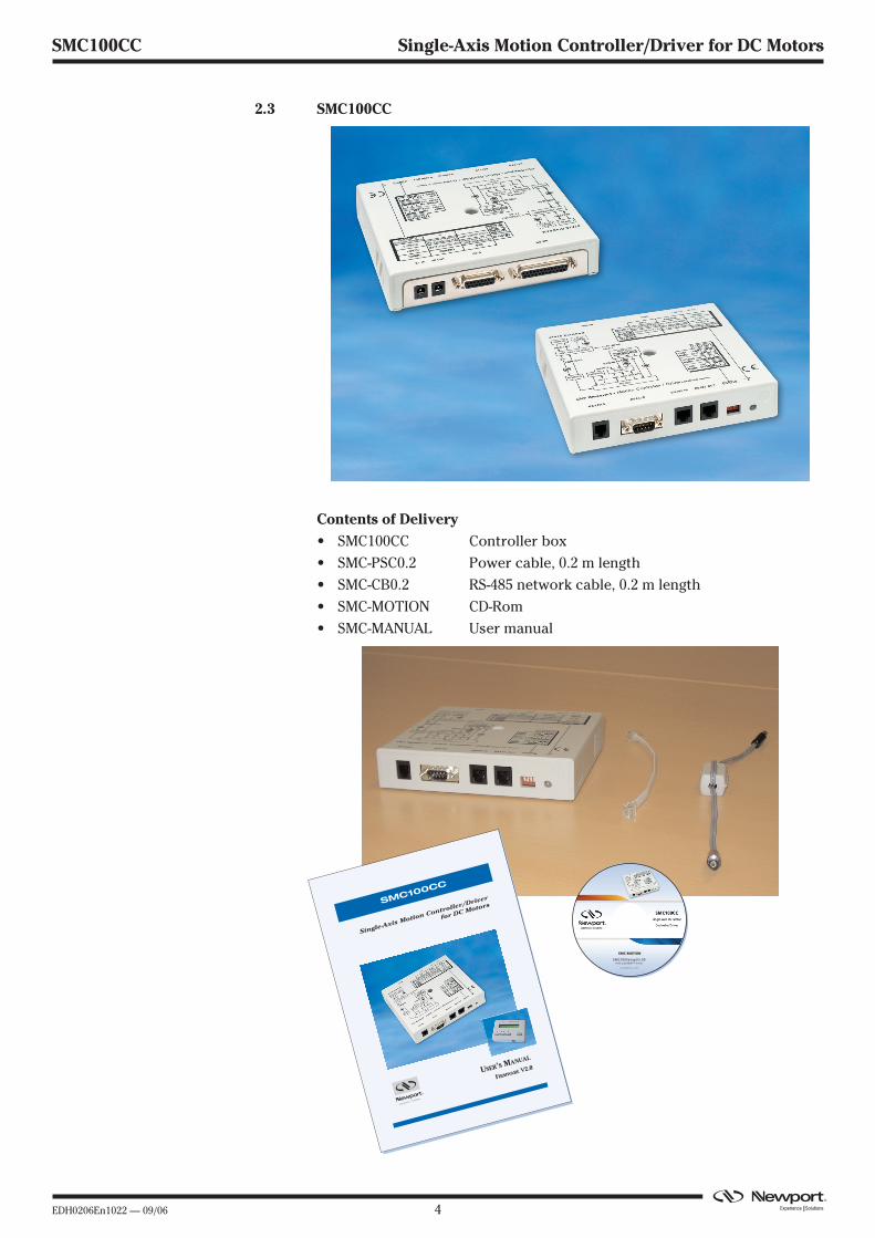
2.3 SMC100CC
2.3.1 Contents of Delivery
• SMC100CC Controller box
• SMC-PSC0.2 Power cable, 0.2 m length
• SMC-CB0.2 RS-485 network cable, 0.2 m length
• SMC-MOTION CD-Rom
• SMC-MANUAL User manual
Single-Axis Motion Controller/Driver
for DC MotorsSMC100CC
USER’S MANUAL
FIRMWARE V2.0
SMC-MOTION
SMC100SetupV2.00with LabVIEW™ driver
DOC0206FE0104 – 12/05

5 EDH0206En1022 — 09/06
SMC100CC Single-Axis Motion Controller/Driver for DC Motors
2.3.2 Specifications
General Description Single-axis motion controller/driver for DC servomotors
Control Capability DC servo motors, open or closed loop operation
Motor Output Power – 48 VDC at 1.5 A rms, 3 A peak– 100 kHz PWM switching frequency
Control loop – Floating point digital PID loop with velocity andfriction feedforward– 2 kHz servo rate– Backlash compensation
Motion Point-to-point motion with S-gamma profile andjerk time control
Computer interface – RS-232-C with 57,600 baud rate– USB compatible with external adapter SMC-USB(requires Windows™ operating system)– RS-485 internal link for chaining up to 31 con-trollers from the same COM port
Programming – 40+ intuitive, 2 letter ASCII commands– Command set includes software limits, userunits, synchronized motion start, stop all
General purpose I/O – 4 TTL out (open collector)– 4 TTL in (2.21 kΩ pull up to 5 V)– 1 analog input, ±10 V, 8-Bit
Dedicated inputs – RS-422 differential encoder inputs for A, B, and I,max. 2 MHz rate– Forward and reverse limit, home switch andindex pulse
Dedicated outputs – 1 open-collector output for “In Motion”– 1 open collector output for “Not Referenced”
Status display Two color LED
Internal safety feature Watchdog timer
2.3.3 Dimensions
5.51(140)
6.34(161)
1.30(33)
1.39(35.3)

EDH0206En1022 — 09/06 6
SMC100CC Single-Axis Motion Controller/Driver for DC Motors
2.4 SMC-RC
2.4.1 Specifications
General description Remote control keypad for SMC100CC
Display 1 line x 16 characters LCD display for position andshort action description of Exec. button depend-ing on controllers state
Function of push buttons (from left to right)– Jog left– High jog velocity (when pressed together with
jog left or jog right)– Jog right– Exec. (function as indicated in display depending
on controllers state)
Cable 0.5 m helix cable, both sides terminatedwith RJ11-4/4 connectors
2.4.2 Dimensions
3.82(97)
2.64(67)
.98(25)

7 EDH0206En1022 — 09/06
SMC100CC Single-Axis Motion Controller/Driver for DC Motors
2.5 SMC-PS80
2.4.1 Specifications
AC Input 100–240 VAC, 47–63 Hz, 1.9 A
DC Output 48 V, 80 W max.
Connector (male Ø 2.1 x Ø 5.5 x 11 mm)
2.4.2 Dimensions
2.6 System Environmental Specifications
Operating temperature 5 °C to 40 °C
Operating humidity < 85% relative humidity, non-condensing
Storage temperature 0 °C to 60 °CRH < 85% relative humidity, non-condensing
Installation category II
Pollution degree 2
Use location Indoor use only
ID 2.1 x OD 5.5
11
Plug Assignment
Standard plug: P2J (option)
P/N
CENTER
OUTPUT
+
P2J
1830+100/-0
SPT-1 18AWGx2C
POWER LED
80 20(typ)
3
R1
NAME PLATE RUBBER FOOTX4
78
.51
.0
22.25
39
.25
168.0 1.0
4-R
4.5
AC INPUTIEC 320 INLET
44
.51
.07
8.5
1.0
EDH0206En1022 — 09/06 8
SMC100CC Single-Axis Motion Controller/Driver for DC Motors
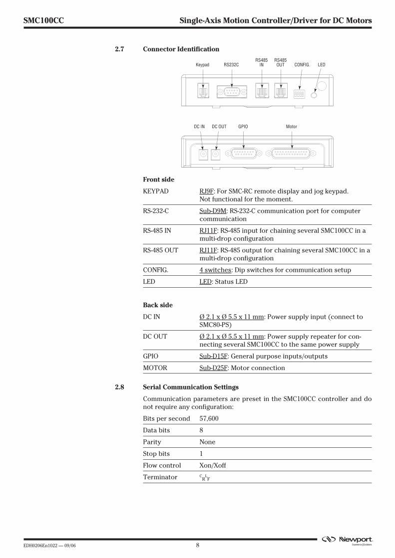
2.7 Connector Identification
Front side
KEYPAD RJ9F: For SMC-RC remote display and jog keypad.Not functional for the moment.
RS-232-C Sub-D9M: RS-232-C communication port for computercommunication
RS-485 IN RJ11F: RS-485 input for chaining several SMC100CC in amulti-drop configuration
RS-485 OUT RJ11F: RS-485 output for chaining several SMC100CC in amulti-drop configuration
CONFIG. 4 switches: Dip switches for communication setup
LED LED: Status LED
Back side
DC IN Ø 2.1 x Ø 5.5 x 11 mm: Power supply input (connect toSMC80-PS)
DC OUT Ø 2.1 x Ø 5.5 x 11 mm: Power supply repeater for con-necting several SMC100CC to the same power supply
GPIO Sub-D15F: General purpose inputs/outputs
MOTOR Sub-D25F: Motor connection
2.8 Serial Communication Settings
Communication parameters are preset in the SMC100CC controller and donot require any configuration:
Bits per second 57,600
Data bits 8
Parity None
Stop bits 1
Flow control Xon/Xoff
Terminator CR
LF
Keypad
DC IN
RS232CRS485
INRS485OUT CONFIG. LED
DC OUT GPIO Motor

9 EDH0206En1022 — 09/06
SMC100CC Single-Axis Motion Controller/Driver for DC Motors
3.0 Getting Started
This section guides the user through the proper set-up of the SMC100CCmotion control system. When using the SMC100CC controller ONLY in localcontrol with the SMC-RC keypad and NOT from a computer, you can skipthis section and continue reading in section 4, SMC100CC with SMC-RC key-pad. If not already done, carefully unpack and visually inspect the con-trollers and the stages for any damage. Place all components on a flat andclean surface.
CAUTION
No cables should be connected to the controller at this point!
First, the controller must be configured properly. When using severalSMC100CC controllers from the same COM port through the internal RS-485communication link, an individual address must be set for each controller.Then, each controller must be configured to the connected stage. For bothsteps, the software supplied with the SMC100CC is used.
3.1 SMC100CC Software Installation
The SMC100CC utility program (SMC100.exe) is designed to run on anycommercially available Pentium™ class desktop personal computer. Thecomputer should have a minimum of 64 MB of RAM. Newport recommendsusing Windows XP™, or Windows 2000™.
For installation, put the CD in your CD drive and double-click on setup.exe.Follow the instructions on the screen.
3.2 Communication Settings
3.2.1 RS-232-C Communication (Using SMC-232 Cable)
Apply the following settings to the COM port of your PC:
Bits per second 57,600
Data bits 8
Parity None
Stop bits 1
Flow control Xon/Xoff
Terminator CR
LF
3.2.2 USB Communication (Using SMC-USB Interface)
Install the software supplied with the SMC-USB on your PC. Follow theinstructions supplied with the SMC-USB.
Apply the following settings to the COM port of your PC:
Bits per second 57,600
Data bits 8
Parity None
Stop bits 1
Flow control Xon/Xoff
Terminator CR
LF
EDH0206En1022 — 09/06 10
SMC100CC Single-Axis Motion Controller/Driver for DC Motors
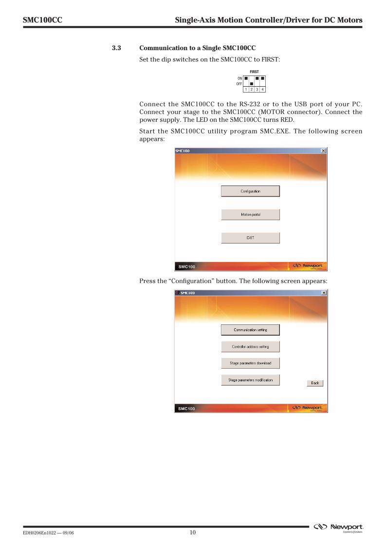
3.3 Communication to a Single SMC100CC
Set the dip switches on the SMC100CC to FIRST:
Connect the SMC100CC to the RS-232 or to the USB port of your PC.Connect your stage to the SMC100CC (MOTOR connector). Connect thepower supply. The LED on the SMC100CC turns RED.
Start the SMC100CC utility program SMC.EXE. The following screenappears:
Press the “Configuration” button. The following screen appears:
1 2 3 4
ONOFF
FIRST
11 EDH0206En1022 — 09/06
SMC100CC Single-Axis Motion Controller/Driver for DC Motors
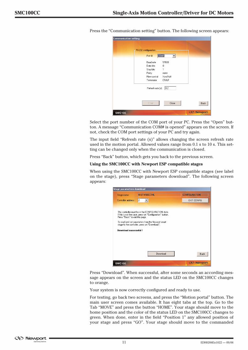
Press the “Communication setting” button. The following screen appears:
Select the port number of the COM port of your PC. Press the “Open” but-ton. A message “Communication COM# is opened” appears on the screen. Ifnot, check the COM port settings of your PC and try again.
The input field “Refresh rate (s)” allows changing the screen refresh rateused in the motion portal. Allowed values range from 0.1 s to 10 s. This set-ting can be changed only when the communication is closed.
Press “Back” button, which gets you back to the previous screen.
Using the SMC100CC with Newport ESP compatible stages
When using the SMC100CC with Newport ESP compatible stages (see labelon the stage), press “Stage parameters download”. The following screenappears:
Press “Download”. When successful, after some seconds an according mes-sage appears on the screen and the status LED on the SMC100CC changesto orange.
Your system is now correctly configured and ready to use.
For testing, go back two screens, and press the “Motion portal” button. Themain user screen comes available. It has eight tabs at the top. Go to theTab “MOVE” and press the button “HOME”. Your stage should move to thehome position and the color of the status LED on the SMC100CC changes togreen. When done, enter in the field “Position 1” any allowed position ofyour stage and press “GO”. Your stage should move to the commanded
EDH0206En1022 — 09/06 12
SMC100CC Single-Axis Motion Controller/Driver for DC Motors
absolute position and the current position gets indicated in the positionfield at the top of the screen. Your system is working correctly and you cannow try the other tabs.
Using the SMC100CC with not ESP compatible stages or changing thedefault values
When using the SMC100CC with not ESP compatible stages, you need toenter the stage parameters manually in the screen “Stage parameters modi-fication”. This screen gets accessed from the “Configuration” screen. In the“Stage parameter configuration” screen you can also change the configura-tion parameters stored in the controller. But it is not recommended doingthis unless you are an experienced user. For further information about themeaning of the different parameters, please refer to the explanations at thecorresponding two letter commands named in brackets in section 5.5.
3.4 Communication to Several SMC100CC
When using several SMC100CC controllers through the internal RS-485 com-munication link, you need to follow specific steps to be successful:
� Apply individual addresses to each controller.
� Connect all elements of the system together.
� Configure each controller to drive the connected stage.
3.4.1 Controller Address Setting
The first thing to do is applying an individual address to each SMC100CCcontroller.
The address of the FIRST controller connected through RS-232-C remainsthe address number 1. You don’t need to do anything with this controller.For addressing the other controllers do the following:
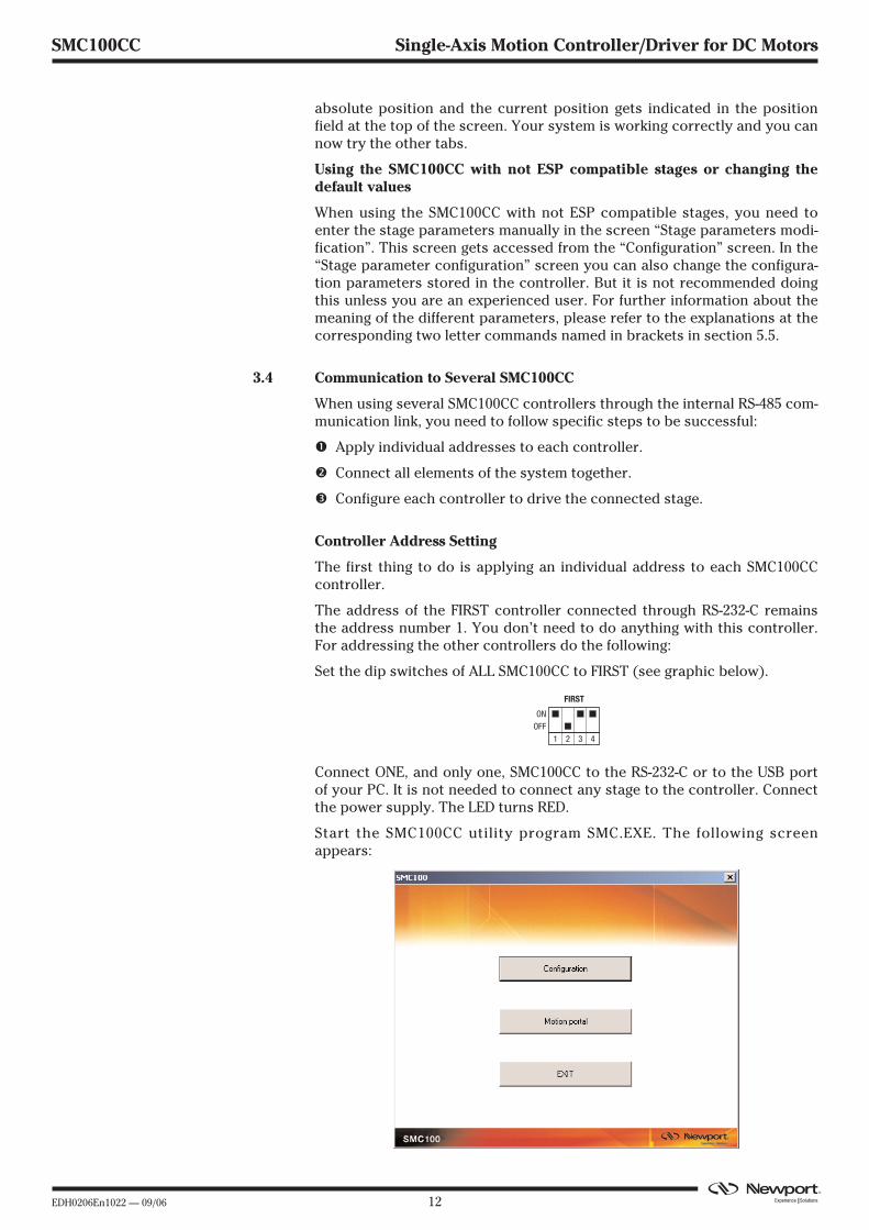
Set the dip switches of ALL SMC100CC to FIRST (see graphic below).
Connect ONE, and only one, SMC100CC to the RS-232-C or to the USB portof your PC. It is not needed to connect any stage to the controller. Connectthe power supply. The LED turns RED.
Start the SMC100CC utility program SMC.EXE. The following screenappears:
1 2 3 4
ONOFF
FIRST
13 EDH0206En1022 — 09/06
SMC100CC Single-Axis Motion Controller/Driver for DC Motors
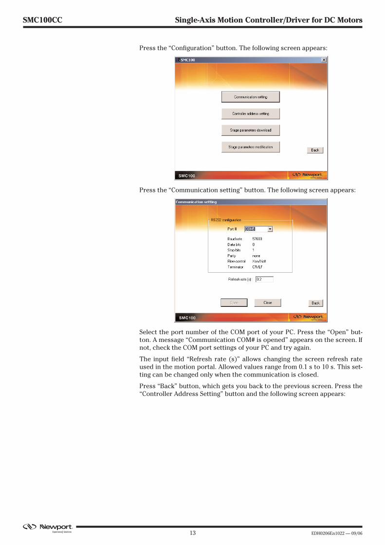
Press the “Configuration” button. The following screen appears:
Press the “Communication setting” button. The following screen appears:
Select the port number of the COM port of your PC. Press the “Open” but-ton. A message “Communication COM# is opened” appears on the screen. Ifnot, check the COM port settings of your PC and try again.
The input field “Refresh rate (s)” allows changing the screen refresh rateused in the motion portal. Allowed values range from 0.1 s to 10 s. This set-ting can be changed only when the communication is closed.
Press “Back” button, which gets you back to the previous screen. Press the“Controller Address Setting” button and the following screen appears:

EDH0206En1022 — 09/06 14
SMC100CC Single-Axis Motion Controller/Driver for DC Motors
Select an address and press the “Set” button. When successful, a messageappears on the screen.
It is recommended to note down the address of the controller somewhere.For example, use the stickers supplied with the SMC100CC.
Now disconnect this controller from your PC and connect the next oneinstead. Select a new, not yet allocated address and press the “Set” buttonagain. Proceed the same with all other controllers.
3.4.2 Building the System
When the addresses of all controllers are set, you can build your system.
Pull out all cables from all controllers. Set the dip switches of the controllerwith the address number 1 as FIRST. Set the dip switches of the other con-trollers, except one, as OTHERS, and set the dip switches of one controlleras LAST. When you have only two controllers, one has to be set as FIRST(the one with the address number 1), and the other one as LAST. See belowgraphic for illustration.
Connect the SMC100CC configured as FIRST to the RS-232-C port or to theUSB port of your PC. Connect a RS-485 network cable to the RS-485 OUT ofthe FIRST controller and to the RS-485 IN of the next controller. Proceed thesame with all other controllers. When done, you can check your system:
• The controller configured as FIRST should have the RS-232-C cable con-nected. It has the address number 1.
• All controllers configured as OTHERS should have one RS-485 networkcable connected to the RS-485 IN and another one to the RS-485 OUT.
• The controller connected as LAST should have one RS-485 networkcable connected to the RS-485 IN.
Connect your stages to the SMC100CC’s (MOTOR connector). Connect yourSMC100CC’s to power.
The SMC100CC allows chaining power from one SMC100CC to another oneusing the SMC-PSC0.2 cable supplied with the controller. But the totalpower consumption of all stages connected to the same power supplyshould not exceed 80 W. The maximum power consumption of eachNewport stage is listed in the Newport catalog and on the Newport website. In case of questions, contact Newport.
1 2 3 4
ONOFF
FIRSTRS232
OTHERSRS485
LASTRS485
1 2 3 4 1 2 3 4
15 EDH0206En1022 — 09/06
SMC100CC Single-Axis Motion Controller/Driver for DC Motors
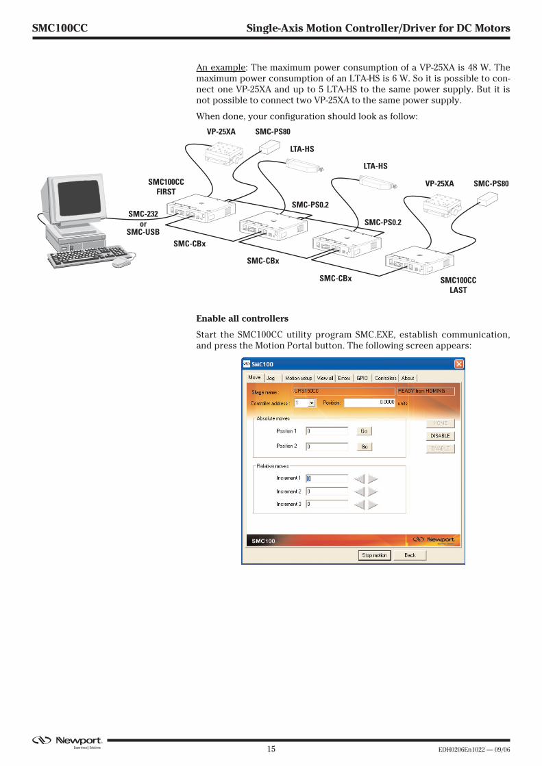
An example: The maximum power consumption of a VP-25XA is 48 W. Themaximum power consumption of an LTA-HS is 6 W. So it is possible to con-nect one VP-25XA and up to 5 LTA-HS to the same power supply. But it isnot possible to connect two VP-25XA to the same power supply.
When done, your configuration should look as follow:
3.4.3 Enable all controllers
Start the SMC100CC utility program SMC.EXE, establish communication,and press the Motion Portal button. The following screen appears:
SMC100CCFIRST
SMC100CCLAST
SMC-CBx
SMC-232or
SMC-USB
SMC-PS80
SMC-PS0.2
SMC-PS0.2
VP-25XA
LTA-HS
VP-25XA
SMC-CBx
SMC-CBx
LTA-HS
SMC-PS80
EDH0206En1022 — 09/06 16
SMC100CC Single-Axis Motion Controller/Driver for DC Motors
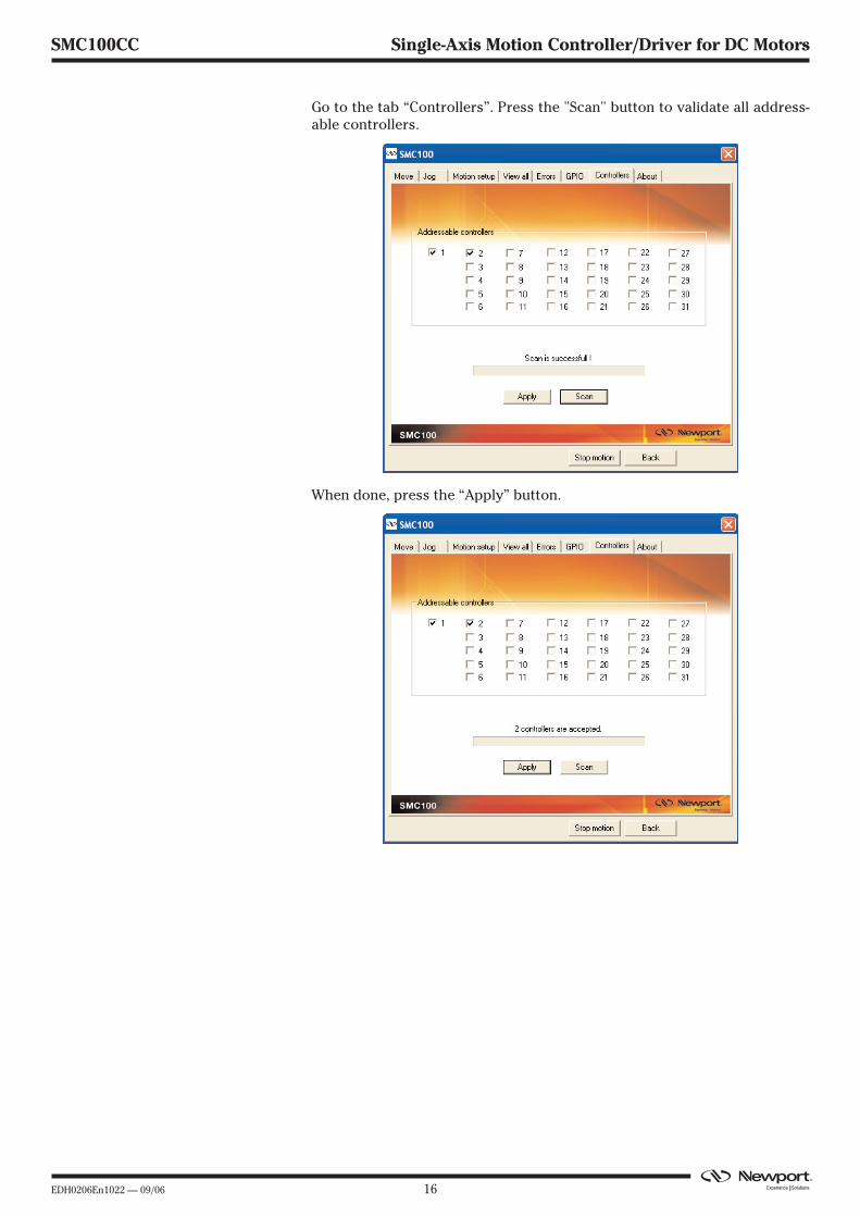
Go to the tab “Controllers”. Press the "Scan" button to validate all address-able controllers.
When done, press the “Apply” button.

17 EDH0206En1022 — 09/06
SMC100CC Single-Axis Motion Controller/Driver for DC Motors
3.4.4 Configuring the Controller
Start the SMC100CC utility program SMC.EXE, establish communication,and go to the Configuration screen.
When using the SMC100CC with Newport ESP compatible stages (see labelon the stage), press “Stage parameters download”. The following screenappears:
Start with the controller address 1. Press “Download”. When successful,after some seconds an according message appears on the screen and thestatus LED on the SMC100CC #1 changes to orange. Select the next avail-able controller address and press “Download” again. Proceed the samewith all other controllers.
When done, your system is configured and ready to use.
For testing, go back two screens, and press the button “Motion portal”. Themain user screen comes available. It has eight tabs at the top. Go to theTab “MOVE”, select controller address 1, and press the button “HOME”.Your stage moves to the home position and the color of the status LED onthe SMC100CC changes to green. When done, enter in the field “Position 1”any allowed position of your stage and press “GO”. Your stage moves tothe commanded absolute position and the current position gets indicatedin the position field at the top of the screen. Select another controlleraddress and do the same. Proceed the same with all other controllers usedin your system.
When everything is ok, your system is working correctly and is ready touse.
Using the SMC100CC with non Newport ESP compatible stages orchanging the default values:
When using the SMC100CC with non Newport ESP compatible stages, youneed to enter the stage parameters manually in the screen “Stage parame-ters modification”. This screen gets accessed from the “Configuration”screen. In the “Stage parameter configuration” screen you can also changethe configuration parameters stored in the controller. But it is not recom-mended doing this unless you are an experienced user. For further informa-tion about the meaning of the different parameters, please refer to theexplanations at the corresponding two letter commands (see commandnames in brackets) in section 5.5.

EDH0206En1022 — 09/06 18
SMC100CC Single-Axis Motion Controller/Driver for DC Motors
4.0 SMC100CC with SMC-RC Keypad
The SMC-RC keypad allows basic use of the SMC100CC controller without acomputer. It features a 16 characters position display and four push but-tons for configuration, jogging, homing, and enabling/disabling motors. Itcan be also used in parallel to a computer control.
If not already done, carefully unpack and visually inspect the SMC100CCcontroller, the SMC-RC keypad, all stages and all accessories for any dam-age. Place all components on a flat and clean surface.
� Connect the SMC-RC to the SMC100CC (KEYPAD connector).
� Connect your stage to the SMC100CC (MOTOR connector).
� Connect the SMC100CC to the SMC-PS80 (DC IN connector).
� Connect the SMC-PS80 to power.
During the initialization, the SMC100CC controller checks if a SMC-RC key-pad is connected. If so, it checks whether all buttons are open (notpressed). If not, an error message gets generated.
NOTE
The SMC100CC does not recognize an SMC-RC after the initialization.Also, disconnecting the SMC-RC from the controller and reconnectingwithout reinitializing the controller does not work.
To reinitialize the SMC100CC controller, temporarily disconnect frompower and reconnect again, or send the RS command (see section 5.5).
When using the SMC100CC for the first time with a Newport ESP compatiblestage (see blue label on the product) a message AUTOCONFIG ? YESgets displayed for about 5 seconds. Press the Exec. button to configure theSMC100CC to the connected stage. Once done, this message gets not dis-played anymore during later initialization unless the SMC100CC recognizesa different Newport ESP compatible stage than the one it is configured to.This message gets also not displayed if the controller is already configuredcorrectly using the SMC100CC software utility (see section 3).
After successful initialization, the controller is in the NOT REFERENCEDstate and the display displays +0.00000 HOM (for more details about theSMC100CC states, please refer to section 5.1). Press the Exec. button tohome the stage. The stage starts moving to its home position. When done,the display shows +0.00000 JOG. The digital value indicates the currentposition of the stage. The default units for Newport positioners are millime-ters for linear stages and actuators, and degrees for rotation stages.
Pressing the Exec. button again gets the controller to the JOGGING stateand the display changes to +0.00000 DIS. The jog buttons “<”, “<< >>”, and“>” are now enabled. Pressing the “<” (jog left) or “>” (Jog right) buttonstarts a motion at slow velocity and with slow acceleration. Releasing thebutton stops the motion. These slow speed motion are ideal for preciseadjustments. Pressing the “<” (jog left) or “>” (Jog right) button and the “<<>>” (high speed) simultaneously starts a high speed motion. These highspeed motion are ideal for coarse adjustments. The jog speed and jogacceleration settings are as follow:

19 EDH0206En1022 — 09/06
SMC100CC Single-Axis Motion Controller/Driver for DC Motors
High jog velocity: Equal to the default velocity (see value set in thesoftware utility or with the VA command).
High jog acceleration: High jog velocity / 2s (means final velocity isreached after 2 seconds).
High jog deceleration: Equal to the default acceleration (see value set inthe software utility or with the AC command).
Low jog velocity: Equal to the default velocity (see value set in thesoftware utility or with the VA command) dividedby 1000.
Low jog acceleration: Low jog velocity / 2s (means final velocity isreached after 2 seconds).
Low jog deceleration: Equal to the default acceleration (see value set inthe software utility or with the AC command).
NOTE
Any jog motion always respects the software limits (see settings in thesoftware utility or with the SL and SR commands). When approaching asoftware limit, the controller decelerates with the programmed accelera-tion even if the jog buttons are pressed.
Pressing the Exec. button when the three most right letters are DIS, getsthe controller to the DISABLE state. In DISABLE state the motor is not ener-gized and the control loop is open. But the encoder is still read and the cur-rent position gets updated. The DISABLE state can be used for instance formanual adjustments or to make sure that no energy goes to the motor. Togo from DISABLE state to the JOGGING state, press the Exec. button again.
The buttons of the keypad can get disabled by the JD command.
NOTE
The keypad does not allow stopping any motion started from a computer(all buttons are disabled when the controller is in MOVING state). Totake computer control when the controller is in JOGGING state the con-troller must first get to the READY state (change state from the softwareutility or by using the JD command).

EDH0206En1022 — 09/06 20
SMC100CC Single-Axis Motion Controller/Driver for DC Motors
5.0 Programming
5.1 State Diagram
For a safe and consistent operation, the SCM100CC uses 7 different opera-tion states: Not referenced, Configuration, Homing, Ready, Disable, Joggingand Moving. In each state, only specific commands are accepted by theSMC100CC. Therefore, it is important to understand the state diagrambelow and which commands and actions cause transition between the dif-ferent states. Also see section 5.5 for command/state information:
When connecting the SMC100CC to power, the controller initializes (seesection 5.2). When the initialization is successful, the controller gets to theNOT REFERENCED state. From the NOT REFERENCED state, the controllercan go to the CONFIGURATION state with the PW1 command. In CONFIGU-RATION stage, the SMC100CC allows changing all stage and motor configu-ration parameters like maximum motor current or travel limits. The PW0command saves all changes to the controller’s memory and returns thecontroller back to the NOT REFERNCED state.
To execute any move commands (PA, PR), the controller must be in READYstate. To get from the NOT REFERENCED state to the READY state, the posi-tioner must be homed first with the OR command. During homing (OR com-mand execution), the controller is in HOMING state. When the homing issuccessful, the controller automatically gets to the READY state. Theprocess for homing, and which signals are looked for during homing, canbe defined with the HT command.
In READY state the motor is energized and the control loop is closed (whencontrol loop state is closed, SC1). During a move execution (PA/PR), thecontroller is in MOVING state and gets automatically back to the READYstate when the move is completed successfully. A following error during amove changes the controller to DISABLE state. Other errors, for instance aloss of the encoder signals, may change the controller to the NOT REFER-ENCED state.
In DISABLE state the motor is not energized and the control loop is open.But the encoder is still read and the current position gets updated. The DIS-ABLE state can be used for instance for manual adjustments or to makesure that no energy goes to the motor. To go from READY state to DISABLEstate and vice versa, use the MM command.
Homing Ready
Hardware FaultNot Referenced
FollowingError
MM0 Following Error Exec. button
Exec.button*
Disable Jogging(<, > and << >> to change speed)
* No action, when jogging speed is different than zero, e.g. one of the keys “<”, “>” or “<< >>” is pressed.
Configuration
PA/PR
MovingExec.button
Following Error
OR
PW1PW0
Exec. button*
Following Error
MM1Done
Done
JD*
21 EDH0206En1022 — 09/06
SMC100CC Single-Axis Motion Controller/Driver for DC Motors
In JOGGING state the controller allows computer independent motion fromthe SMC-RC keypad. The controller can get to the JOGGING state ONLY bypressing the Exec. button on the SMC-RC when the controller is in theREADY or in the DISABLE state. To get from JOGGING state to READY stateuse the JD command.
To get from READY state or DISABLE state back to the NOT REFERENCEDstate, for instance to make some further parameter change in CONFIGURA-TION state, you need to reboot the controller with the RS command.
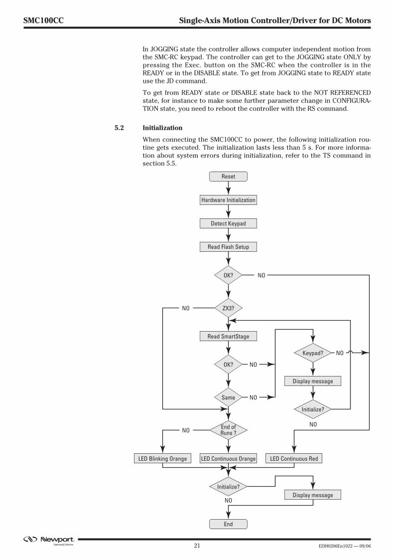
5.2 Initialization
When connecting the SMC100CC to power, the following initialization rou-tine gets executed. The initialization lasts less than 5 s. For more informa-tion about system errors during initialization, refer to the TS command insection 5.5.
Reset
End
Hardware Initialization
LED Continuous OrangeLED Blinking Orange LED Continuous Red
Read Flash Setup
OK?
ZX3?
OK?
Same
End ofRuns ?
NO
NONO
NO
NO
NO
NO
NO
Detect Keypad
Read SmartStage
Keypad?
Initialize?
Initialize?
Display message
Display message

EDH0206En1022 — 09/06 22
SMC100CC Single-Axis Motion Controller/Driver for DC Motors
5.3 Command Syntax
The SMC100CC is a command driven controller. The general format of acommand is a two letter ASCII character preceded and followed by parame-ters specific to the command:
Command format:
nn — Optional or required controller address.
AA — Command name.
xx — Optional or required value or “?” to query current value.
Both, upper and lower case characters are accepted. Depending on thecommand, it can have an optional or required prefix (nn) for the controlleraddress and/or a suffix (xx) value or a “?”.
Blank spaces
Blanks are allowed and ignored in any position, including inside a numeri-cal value. The following two commands are equivalent, but the first exam-ple might be confusing and uses more memory:
2P A1.43 6
2PA1.436
Decimal separator
A dot (“.”) is used as decimal separator for all numerical values.
Command terminator
Commands are executed as the command terminator CR
LF (carriage-return
line-feed, ASCII 13 and ASCII 10) is received. The controller will analyze thereceived string. If the command is valid and its parameters are in the speci-fied range, it will be executed. Otherwise it will memorize an error.
After the execution of the command, all remaining characters in the inputstring, if any, will be ignored. In particular, it is not possible to concatenateseveral commands on a single string from the PC to the SMC100.
Each command will handle properly the memorization of related errorsthat can be accessed with the TE command. Please refer to the commandset in section 5.5 for details.
5.4 Command Execution Time
The SMC100CC controller interprets commands continuously as received.The typical execution time for a "tell position command" (nTP?) is about 10ms for the first controller (controller address number 1) and about 16 msfor the other controllers. Here, command execution time means the timefrom sending the command until receive of the answer.
It is important to note that a move command, that may lasts for severalseconds, will not suspend the controller from further command execution.So for an efficient process flow with many move commands it is recom-mended to use the PT command (get time for a relative move), and toquery the controller status (TS command) or the current position (TP com-mand) before any further motion command is sent. Alternative, the dedi-cated outputs "In Motion" and "Not Referenced" can be used for similarpurposes. These will provide an even more timely accurate information ofthe controller state.
xxAAnn
23 EDH0206En1022 — 09/06
SMC100CC Single-Axis Motion Controller/Driver for DC Motors
5.5 Command Set
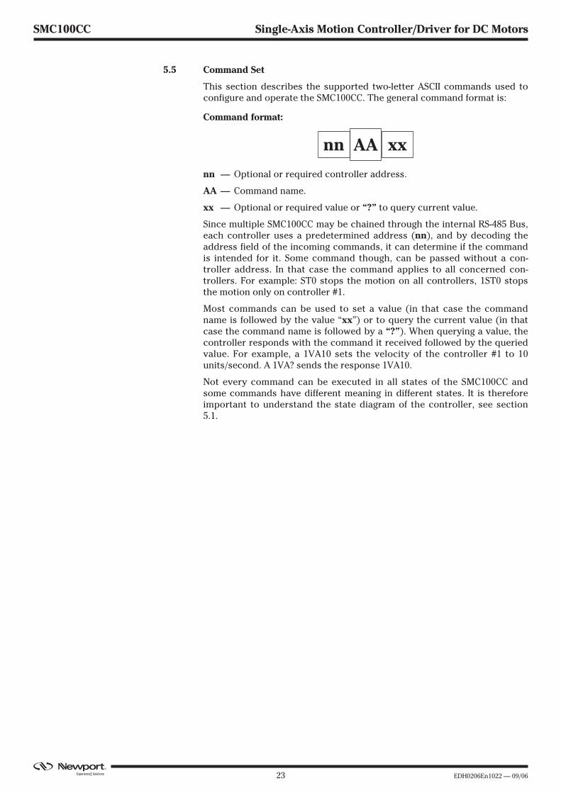
This section describes the supported two-letter ASCII commands used toconfigure and operate the SMC100CC. The general command format is:
Command format:
nn — Optional or required controller address.
AA — Command name.
xx — Optional or required value or “?” to query current value.
Since multiple SMC100CC may be chained through the internal RS-485 Bus,each controller uses a predetermined address (nn), and by decoding theaddress field of the incoming commands, it can determine if the commandis intended for it. Some command though, can be passed without a con-troller address. In that case the command applies to all concerned con-trollers. For example: ST0 stops the motion on all controllers, 1ST0 stopsthe motion only on controller #1.
Most commands can be used to set a value (in that case the commandname is followed by the value “xx”) or to query the current value (in thatcase the command name is followed by a “?”). When querying a value, thecontroller responds with the command it received followed by the queriedvalue. For example, a 1VA10 sets the velocity of the controller #1 to 10units/second. A 1VA? sends the response 1VA10.
Not every command can be executed in all states of the SMC100CC andsome commands have different meaning in different states. It is thereforeimportant to understand the state diagram of the controller, see section5.1.
xxAAnn

EDH0206En1022 — 09/06 24
SMC100CC Single-Axis Motion Controller/Driver for DC Motors
Not Ref. Config. Disable Ready Motion Jogging Description
AC � � � Set/Get acceleration
BA � Set/Get backlash compensation
BH � Set/Get hysteresis compensation
DV � Set/Get driver voltage
FD � � Set/Get low pass filter for Kd
FE � � Set/Get following error limit
FF � � Set/Get friction compensation
HT � Set/Get HOME search type
ID � Set/Get stage identifier
JD � Leave JOGGING state
JM � � � Enable/disable keypad
JR � � � Set/Get jerk time
KD � � Set/Get derivative gain
KI � � Set/Get integral gain
KP � � Set/Get proportional gain
KV � � Set/Get velocity feed forward
MM � � Enter/Leave DISABLE state
OH � Set/Get HOME search velocity
OR � Execute HOME search
OT � Set/Get HOME search time-out
PA � Move absolute
PR � Move relative
PT � � � Get motion time for a relative move
PW � � Enter/Leave CONFIGURATION state
QI � Set/Get motor’s current limits
RA � � � � � � Get analog input value
RB � � � � � � Get TTL input value
RS � � Reset controller
SA � Set/Get controller’s RS-485 address
SB � � � � Set/Get TTL output value
SC � Set/Get control loop state
SE � Configure/Execute simultaneous started move
SL � � � Set/Get negative software limit
SR � � � Set/Get positive software limit
ST � � � Stop motion
SU � Set/Get encoder increment value
TB � � � � � � Get command error string
TE � � � � � Get last command error
TH � � � � � � Get set-point position
TP � � � � � � Get current position
TS � � � � � � Get positioner error and controller state
VA � � � Set/Get velocity
VE � � � � � � Get controller revision information
ZT � � � � � Get all axis parameters
ZX � Set/Get SmartStage configuration

25 EDH0206En1022 — 09/06
SMC100CC Single-Axis Motion Controller/Driver for DC Motors
Motion: Corresponds to HOMING and MOVING state (for details seestate diagram, section 5.1).
� Changes configuration parameters. Those changes will bestored in the controller’s memory with the PW1 command andremain available after switching off the controller.
� Changes working parameters only. Those changes will get lostwhen switching off the controller.
� Accepted command.
Blank: Not accepted command (will return an error).
Command: Command passed without preceding controller numberapplies to all controllers (e.g. MM0 disables all controllers).

EDH0206En1022 — 09/06 26
SMC100CC AC — Set/Get acceleration
Usage Not Ref. Config. Disable Ready Motion Jogging� � � � � �
Syntax xxACnn, or xxAC?
Parameters
Description xx [int] — Controller address.nn [float] — Acceleration value.
Range xx — 1 to 31nn — > 10-6 and < 1012
Units xx — Nonenn — Preset units/s2
Defaults xx Missing: Error B.Out of range: Error B.
Floating point: Error A.
nn Missing: Error C.Out of range: Error C.
Description In CONFIGURATION state, this command sets the maximum accelerationvalue which can than be saved in the controller’s nonvolatile memoryusing the PW command. This is the maximum acceleration that can beapplied to the mechanical system. It is also the default acceleration thatwill be used for all moves unless a lower value is set in DISABLE or READYstate.
In DISABLE or READY state, this command sets the acceleration used forthe following moves. Its value can be up to the programmed value in CON-FIGURATION state. This value is not saved in the controller’s memory andwill be lost after reboot.
Returns If the sign “?” takes place of nn, this command returns the current pro-grammed value.
Errors A — Unknown message code or floating point controller address.B — Controller address not correct.C — Parameter missing or out of range.D — Execution not allowed.H — Execution not allowed in NOT REFERENCED state.L — Execution not allowed in HOMING state.M — Execution not allowed in MOVING state.
Rel. Commands VA — Set velocity.
Example 1AC500 | Set controller #1 acceleration to 500 units/s2.1AC? | Controller returns 1AC500.
27 EDH0206En1022 — 09/06
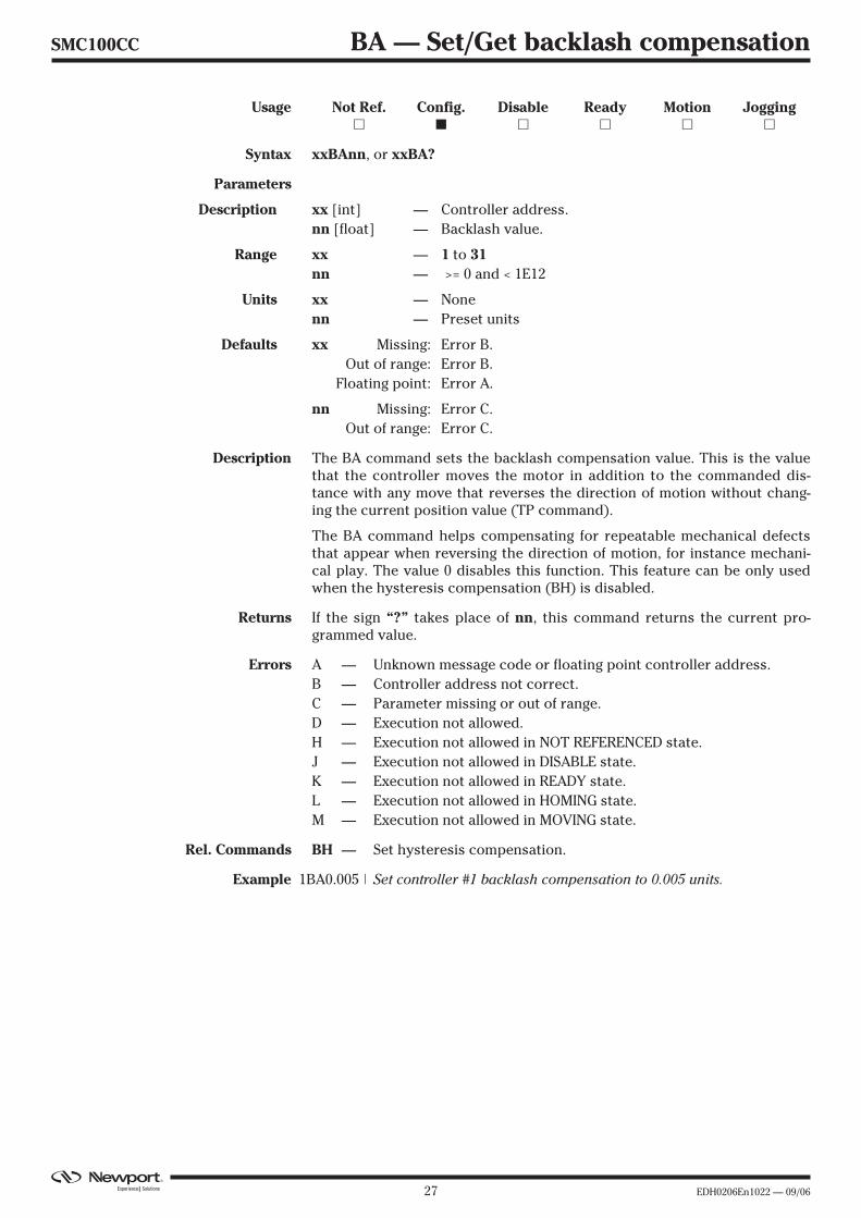
SMC100CC BA — Set/Get backlash compensation
Usage Not Ref. Config. Disable Ready Motion Jogging� � � � � �
Syntax xxBAnn, or xxBA?
Parameters
Description xx [int] — Controller address.nn [float] — Backlash value.
Range xx — 1 to 31nn — >= 0 and < 1E12
Units xx — Nonenn — Preset units
Defaults xx Missing: Error B.Out of range: Error B.
Floating point: Error A.
nn Missing: Error C.Out of range: Error C.
Description The BA command sets the backlash compensation value. This is the valuethat the controller moves the motor in addition to the commanded dis-tance with any move that reverses the direction of motion without chang-ing the current position value (TP command).
The BA command helps compensating for repeatable mechanical defectsthat appear when reversing the direction of motion, for instance mechani-cal play. The value 0 disables this function. This feature can be only usedwhen the hysteresis compensation (BH) is disabled.
Returns If the sign “?” takes place of nn, this command returns the current pro-grammed value.
Errors A — Unknown message code or floating point controller address.B — Controller address not correct.C — Parameter missing or out of range.D — Execution not allowed.H — Execution not allowed in NOT REFERENCED state.J — Execution not allowed in DISABLE state.K — Execution not allowed in READY state.L — Execution not allowed in HOMING state.M — Execution not allowed in MOVING state.
Rel. Commands BH — Set hysteresis compensation.
Example 1BA0.005 | Set controller #1 backlash compensation to 0.005 units.

EDH0206En1022 — 09/06 28
SMC100CC BH — Set/Get hysteresis compensation
Usage Not Ref. Config. Disable Ready Motion Jogging� � � � � �
Syntax xxBHnn, or xxBH?
Parameters
Description xx [int] — Controller address.nn [float] — Hysteresis value.
Range xx — 1 to 31nn — ≥ 0 and < 1012
Units xx — Nonenn — Preset units
Defaults xx Missing: Error B.Out of range: Error B.
Floating point: Error A.
nn Missing: Error C.Out of range: Error C.
Description The BH command sets the hysteresis compensation value. When set to avalue different than zero, the controller will issue for each move in the pos-itive direction a move of the commanded distance plus the hysteresis com-pensation value, and then a second move of the hysteresis compensationvalue in the negative direction. This motion ensures that a final positiongets always approached from the same direction and distance and helpscompensating for non-repeatable mechanical defects like hysteresis ormechanical stiffness variations.
The value 0 disables this function. The BH command can not be used whenthe backlash compensation is enabled (BA command).
Returns If the sign “?” takes place of nn, this command returns the current pro-grammed value.
Errors A — Unknown message code or floating point controller address.B — Controller address not correct.C — Parameter missing or out of range.D — Execution not allowed.H — Execution not allowed in NOT REFERENCED state.J — Execution not allowed in DISABLE state.K — Execution not allowed in READY state.L — Execution not allowed in HOMING state.M — Execution not allowed in MOVING state.
Rel. Commands BA — Set backlash compensation.
Example 1BH0.015 | Set controller #1 backlash compensation to 0.015 units.

29 EDH0206En1022 — 09/06
SMC100CC DV — Set/Get driver voltage
Usage Not Ref. Config. Disable Ready Motion Jogging� � � � � �
Syntax xxDVnn, or xxDV?
Parameters
Description xx [int] — Controller address.nn [float] — Driver voltage value.
Range xx — 1 to 31nn — ≥ 12 & ≤ 48
Units xx — None.nn — Volts
Defaults xx Missing: Error B.Out of range: Error B.
Floating point: Error A.
nn Missing: Error C.Out of range: Error C.
Description This command sets the max. output voltage of the driver to the motor.
Returns If the sign “?” takes place of nn, this command returns the current pro-grammed value.
Errors A — Unknown message code or floating point controller address.B — Controller address not correct.C — Parameter missing or out of range.D — Execution not allowed.H — Execution not allowed in NOT REFERENCED state.J — Execution not allowed in DISABLE state.K — Execution not allowed in READY state.L — Execution not allowed in HOMING state.M — Execution not allowed in MOVING state.
Rel. Commands QI — Set current limit.
Example 1DV48 | Set controller #1 maximum output voltage to 48 V.
EDH0206En1022 — 09/06 30
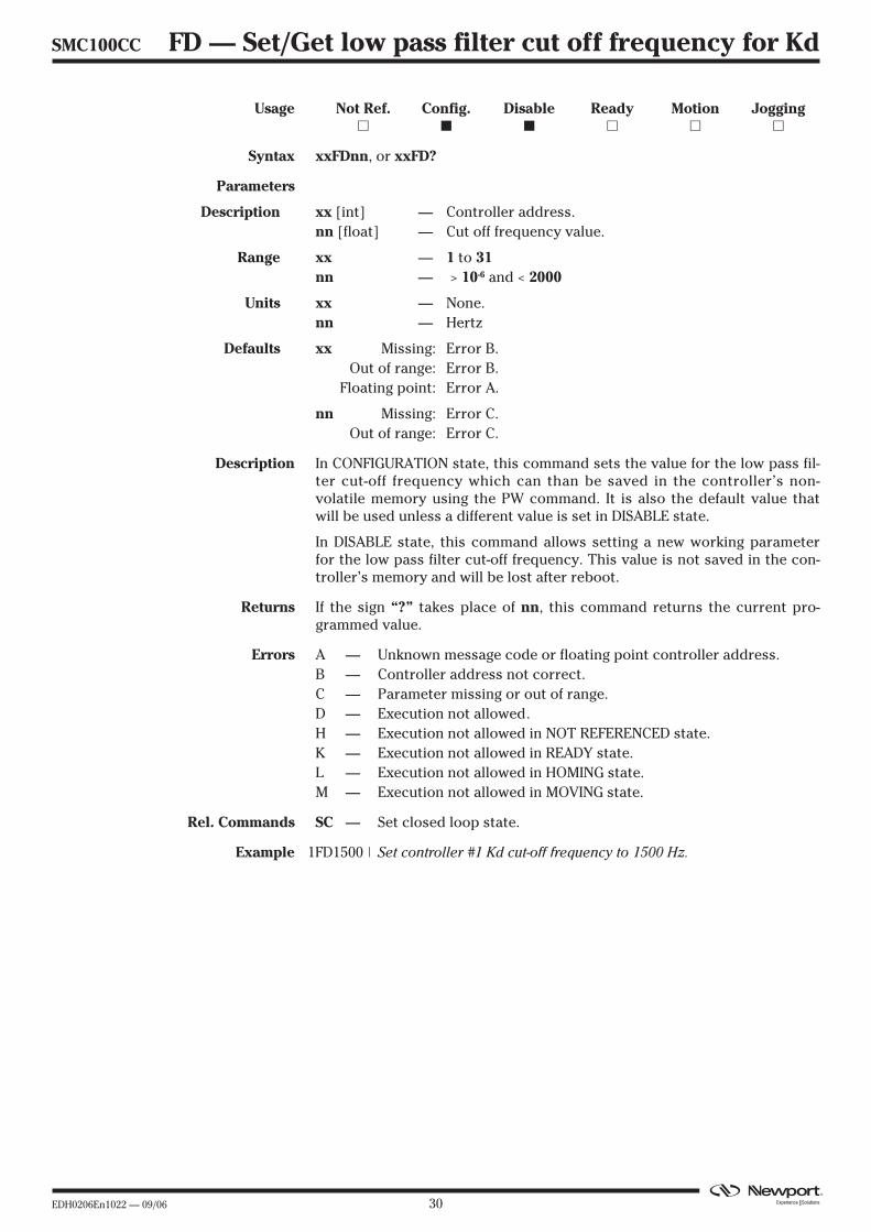
SMC100CC FD — Set/Get low pass filter cut off frequency for Kd
Usage Not Ref. Config. Disable Ready Motion Jogging� � � � � �
Syntax xxFDnn, or xxFD?
Parameters
Description xx [int] — Controller address.nn [float] — Cut off frequency value.
Range xx — 1 to 31nn — > 10-6 and < 2000
Units xx — None.nn — Hertz
Defaults xx Missing: Error B.Out of range: Error B.
Floating point: Error A.
nn Missing: Error C.Out of range: Error C.
Description In CONFIGURATION state, this command sets the value for the low pass fil-ter cut-off frequency which can than be saved in the controller’s non-volatile memory using the PW command. It is also the default value thatwill be used unless a different value is set in DISABLE state.
In DISABLE state, this command allows setting a new working parameterfor the low pass filter cut-off frequency. This value is not saved in the con-troller’s memory and will be lost after reboot.
Returns If the sign “?” takes place of nn, this command returns the current pro-grammed value.
Errors A — Unknown message code or floating point controller address.B — Controller address not correct.C — Parameter missing or out of range.D — Execution not allowed.H — Execution not allowed in NOT REFERENCED state.K — Execution not allowed in READY state.L — Execution not allowed in HOMING state.M — Execution not allowed in MOVING state.
Rel. Commands SC — Set closed loop state.
Example 1FD1500 | Set controller #1 Kd cut-off frequency to 1500 Hz.
31 EDH0206En1022 — 09/06
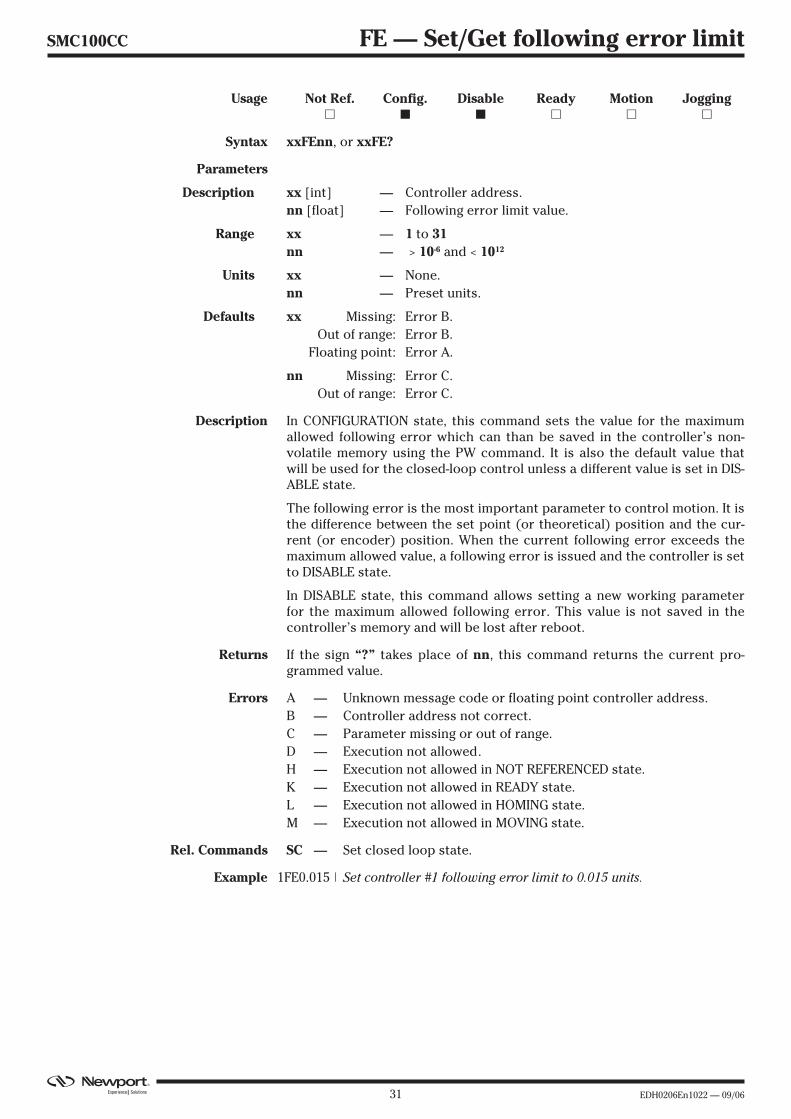
SMC100CC FE — Set/Get following error limit
Usage Not Ref. Config. Disable Ready Motion Jogging� � � � � �
Syntax xxFEnn, or xxFE?
Parameters
Description xx [int] — Controller address.nn [float] — Following error limit value.
Range xx — 1 to 31nn — > 10-6 and < 1012
Units xx — None.nn — Preset units.
Defaults xx Missing: Error B.Out of range: Error B.
Floating point: Error A.
nn Missing: Error C.Out of range: Error C.
Description In CONFIGURATION state, this command sets the value for the maximumallowed following error which can than be saved in the controller’s non-volatile memory using the PW command. It is also the default value thatwill be used for the closed-loop control unless a different value is set in DIS-ABLE state.
The following error is the most important parameter to control motion. It isthe difference between the set point (or theoretical) position and the cur-rent (or encoder) position. When the current following error exceeds themaximum allowed value, a following error is issued and the controller is setto DISABLE state.
In DISABLE state, this command allows setting a new working parameterfor the maximum allowed following error. This value is not saved in thecontroller’s memory and will be lost after reboot.
Returns If the sign “?” takes place of nn, this command returns the current pro-grammed value.
Errors A — Unknown message code or floating point controller address.B — Controller address not correct.C — Parameter missing or out of range.D — Execution not allowed.H — Execution not allowed in NOT REFERENCED state.K — Execution not allowed in READY state.L — Execution not allowed in HOMING state.M — Execution not allowed in MOVING state.
Rel. Commands SC — Set closed loop state.
Example 1FE0.015 | Set controller #1 following error limit to 0.015 units.
EDH0206En1022 — 09/06 32
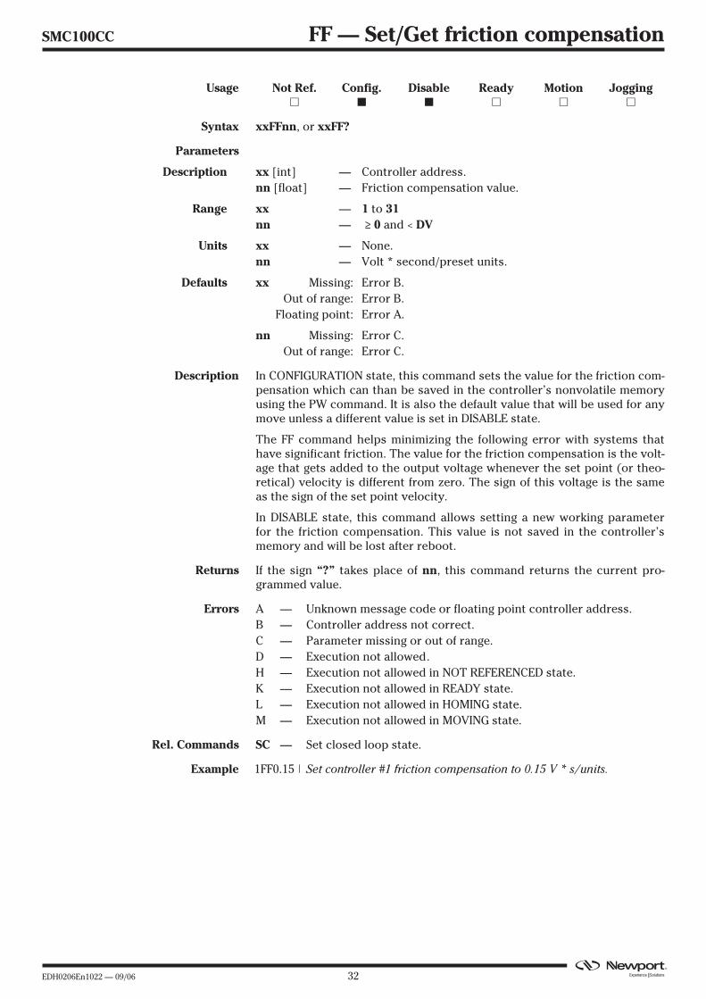
SMC100CC FF — Set/Get friction compensation
Usage Not Ref. Config. Disable Ready Motion Jogging� � � � � �
Syntax xxFFnn, or xxFF?
Parameters
Description xx [int] — Controller address.nn [float] — Friction compensation value.
Range xx — 1 to 31nn — ≥ 0 and < DV
Units xx — None.nn — Volt * second/preset units.
Defaults xx Missing: Error B.Out of range: Error B.
Floating point: Error A.
nn Missing: Error C.Out of range: Error C.
Description In CONFIGURATION state, this command sets the value for the friction com-pensation which can than be saved in the controller’s nonvolatile memoryusing the PW command. It is also the default value that will be used for anymove unless a different value is set in DISABLE state.
The FF command helps minimizing the following error with systems thathave significant friction. The value for the friction compensation is the volt-age that gets added to the output voltage whenever the set point (or theo-retical) velocity is different from zero. The sign of this voltage is the sameas the sign of the set point velocity.
In DISABLE state, this command allows setting a new working parameterfor the friction compensation. This value is not saved in the controller’smemory and will be lost after reboot.
Returns If the sign “?” takes place of nn, this command returns the current pro-grammed value.
Errors A — Unknown message code or floating point controller address.B — Controller address not correct.C — Parameter missing or out of range.D — Execution not allowed.H — Execution not allowed in NOT REFERENCED state.K — Execution not allowed in READY state.L — Execution not allowed in HOMING state.M — Execution not allowed in MOVING state.
Rel. Commands SC — Set closed loop state.
Example 1FF0.15 | Set controller #1 friction compensation to 0.15 V * s/units.

33 EDH0206En1022 — 09/06
SMC100CC HT — Set/Get HOME search type
Usage Not Ref. Config. Disable Ready Motion Jogging� � � � � �
Syntax xxHTnn, or xxHT?
Parameters
Description xx [int] — Controller address.nn [int] — Home type value.
Range xx — 1 to 31nn — 0 use MZ switch and encoder Index.
1 use current position as HOME.2 use MZ switch only.3 use EoR- switch and encoder Index.4 use EoR- switch only.
Units xx — None.nn — None.
Defaults xx Missing: Error B.Out of range: Error B.
Floating point: Error A.
nn Missing: Error C.Out of range: Error C.
Description This command sets the type of HOME search used with the OR command.
Returns If the sign “?” takes place of nn, this command returns the current pro-grammed value.
Errors A — Unknown message code or floating point controller address.B — Controller address not correct.C — Parameter missing or out of range.D — Execution not allowed.H — Execution not allowed in NOT REFERENCED state.J — Execution not allowed in DISABLE state.K — Execution not allowed in READY state.L — Execution not allowed in HOMING state.M — Execution not allowed in MOVING state.
Rel. Commands OR — Execute HOME search.
Example 1HT0 | Set controller #1 HOME sequence to use MZ and encoder index.

EDH0206En1022 — 09/06 34
SMC100CC ID — Set/Get stage identifier
Usage Not Ref. Config. Disable Ready Motion Jogging� � � � � �
Syntax xxIDnn, or xxID?
Parameters
Description xx [int] — Controller address.nn [float] — Stage model number.
Range xx — 1 to 31nn — 1 to 31 ASCII characters.
Units xx — Nonenn — None
Defaults xx Missing: Error B.Out of range: Error B.
Floating point: Error A.
nn Missing: Error C.Out of range: Error C.
Description The ID? command return the stage identifier. When used with Newport ESPcompatible stages (see blue label on the product), this is the identical tothe Newport product name. In CONFIGURATION mode, this commandallows changing the stage identifier. However, customer should never dothis when the ESP stage configuration is enabled (ZX3).
Returns If the sign “?” takes place of nn, this command returns the current pro-grammed value.
Errors A — Unknown message code or floating point controller address.B — Controller address not correct.C — Parameter missing or out of range.D — Execution not allowed.H — Execution not allowed in NOT REFERENCED state.J — Execution not allowed in DISABLE state.K — Execution not allowed in READY state.L — Execution not allowed in HOMING state.M — Execution not allowed in MOVING state.
Rel. Commands ZX — Set SmartStage configuration.
Example 1ID? | Get stage identifier for controller #1.| Controller returns URS100CC.
35 EDH0206En1022 — 09/06
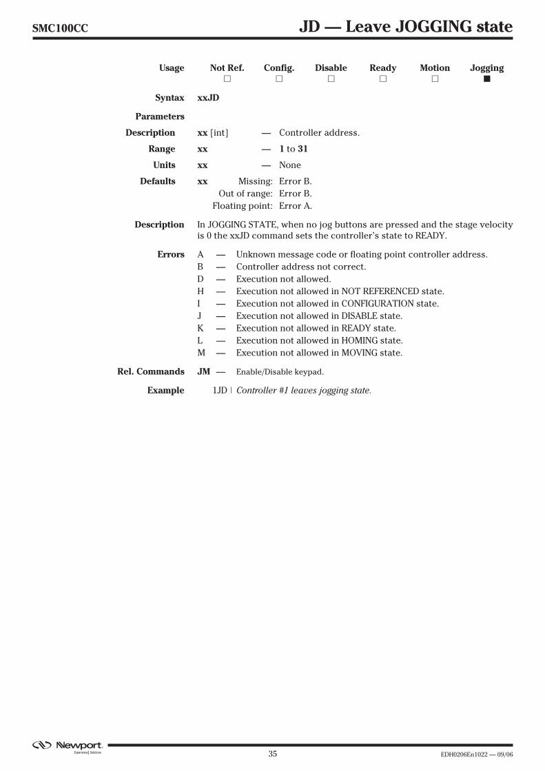
SMC100CC JD — Leave JOGGING state
Usage Not Ref. Config. Disable Ready Motion Jogging� � � � � �
Syntax xxJD
Parameters
Description xx [int] — Controller address.
Range xx — 1 to 31
Units xx — None
Defaults xx Missing: Error B.Out of range: Error B.
Floating point: Error A.
Description In JOGGING STATE, when no jog buttons are pressed and the stage velocityis 0 the xxJD command sets the controller’s state to READY.
Errors A — Unknown message code or floating point controller address.B — Controller address not correct.D — Execution not allowed.H — Execution not allowed in NOT REFERENCED state.I — Execution not allowed in CONFIGURATION state.J — Execution not allowed in DISABLE state.K — Execution not allowed in READY state.L — Execution not allowed in HOMING state.M — Execution not allowed in MOVING state.
Rel. Commands JM — Enable/Disable keypad.
Example 1JD | Controller #1 leaves jogging state.
EDH0206En1022 — 09/06 36
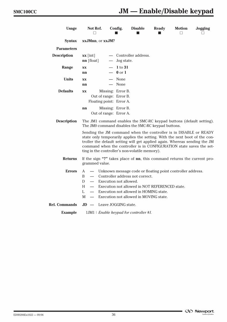
SMC100CC JM — Enable/Disable keypad
Usage Not Ref. Config. Disable Ready Motion Jogging� � � � � �
Syntax xxJMnn, or xxJM?
Parameters
Description xx [int] — Controller address.nn [float] — Jog state.
Range xx — 1 to 31nn — 0 or 1
Units xx — Nonenn — None
Defaults xx Missing: Error B.Out of range: Error B.
Floating point: Error A.
nn Missing: Error B.Out of range: Error A.
Description The JM1 command enables the SMC-RC keypad buttons (default setting).The JM0 command disables the SMC-RC keypad buttons.
Sending the JM command when the controller is in DISABLE or READYstate only temporarily applies the setting. With the next boot of the con-troller the default setting will get applied again. Whereas sending the JMcommand when the controller is in CONFIGURATION state saves the set-ting in the controller’s non-volatile memory).
Returns If the sign “?” takes place of nn, this command returns the current pro-grammed value.
Errors A — Unknown message code or floating point controller address.B — Controller address not correct.D — Execution not allowed.H — Execution not allowed in NOT REFERENCED state.L — Execution not allowed in HOMING state.M — Execution not allowed in MOVING state.
Rel. Commands JD — Leave JOGGING state.
Example 1JM1 | Enable keypad for controller #1.
37 EDH0206En1022 — 09/06
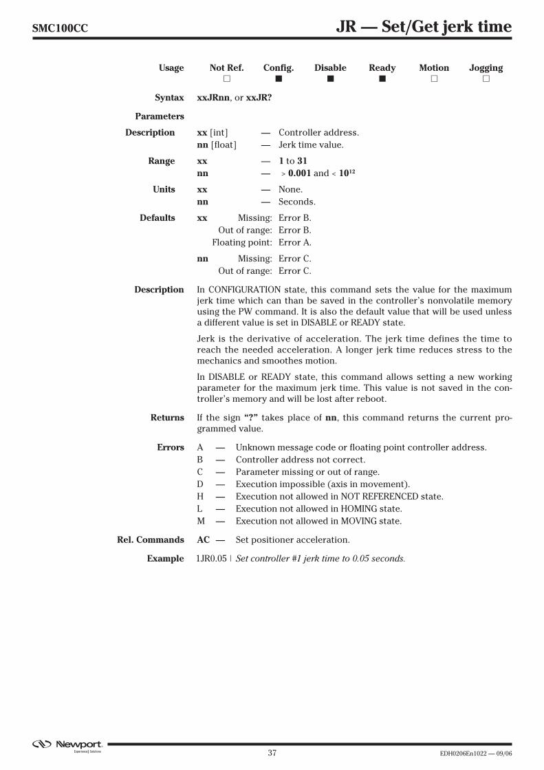
SMC100CC JR — Set/Get jerk time
Usage Not Ref. Config. Disable Ready Motion Jogging� � � � � �
Syntax xxJRnn, or xxJR?
Parameters
Description xx [int] — Controller address.nn [float] — Jerk time value.
Range xx — 1 to 31nn — > 0.001 and < 1012
Units xx — None.nn — Seconds.
Defaults xx Missing: Error B.Out of range: Error B.
Floating point: Error A.
nn Missing: Error C.Out of range: Error C.
Description In CONFIGURATION state, this command sets the value for the maximumjerk time which can than be saved in the controller’s nonvolatile memoryusing the PW command. It is also the default value that will be used unlessa different value is set in DISABLE or READY state.
Jerk is the derivative of acceleration. The jerk time defines the time toreach the needed acceleration. A longer jerk time reduces stress to themechanics and smoothes motion.
In DISABLE or READY state, this command allows setting a new workingparameter for the maximum jerk time. This value is not saved in the con-troller’s memory and will be lost after reboot.
Returns If the sign “?” takes place of nn, this command returns the current pro-grammed value.
Errors A — Unknown message code or floating point controller address.B — Controller address not correct.C — Parameter missing or out of range.D — Execution impossible (axis in movement).H — Execution not allowed in NOT REFERENCED state.L — Execution not allowed in HOMING state.M — Execution not allowed in MOVING state.
Rel. Commands AC — Set positioner acceleration.
Example 1JR0.05 | Set controller #1 jerk time to 0.05 seconds.

EDH0206En1022 — 09/06 38
SMC100CC KD — Set/Get derivative gain
Usage Not Ref. Config. Disable Ready Motion Jogging� � � � � �
Syntax xxKDnn, or xxKD?
Parameters
Description xx [int] — Controller address.nn [float] — Derivative gain value.
Range xx — 1 to 31nn — ≥ 0 and < 1012
Units xx — None.nn — Volt * second/preset unit.
Defaults xx Missing: Error B.Out of range: Error B.
Floating point: Error A.
nn Missing: Error C.Out of range: Error C.
Description In CONFIGURATION state, this command sets the derivative gain of the PIDcontrol loop which can than be saved in the controller’s nonvolatile memo-ry using the PW command. It is also the default value that will be usedunless a different value is set in DISABLE state.
In DISABLE state, this command allows setting a new working parameterfor the derivative gain. This value is not saved in the controller’s memoryand will be lost after reboot.
Returns If the sign “?” takes place of nn, this command returns the current pro-grammed value.
Errors A — Unknown message code or floating point controller address.B — Controller address not correct.C — Parameter missing or out of range.D — Execution not allowed.H — Execution not allowed in NOT REFERENCED state.K — Execution not allowed in READY state.L — Execution not allowed in HOMING state.M — Execution not allowed in MOVING state.
Rel. Commands SC — Set closed loop state.KI — Set integral gain.KP — Set proportional gain.KV — Set velocity feed forward.
Example 1KD0.015 | Set controller #1 derivative gain to 0.015.
39 EDH0206En1022 — 09/06
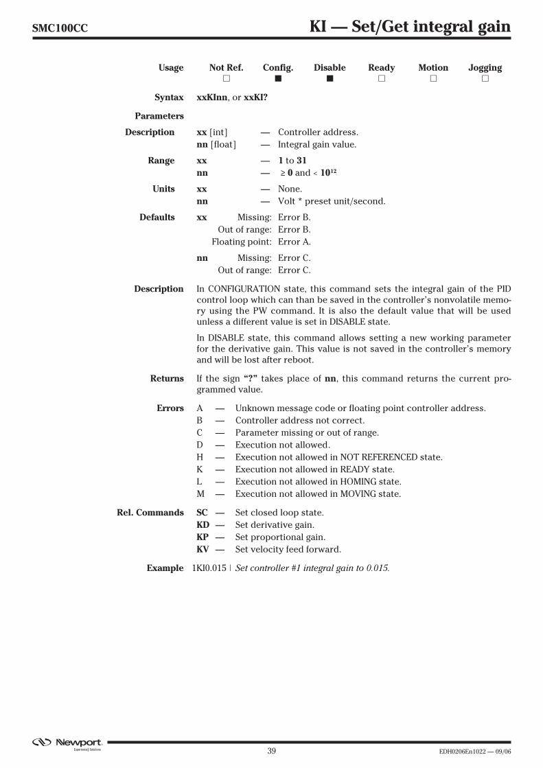
SMC100CC KI — Set/Get integral gain
Usage Not Ref. Config. Disable Ready Motion Jogging� � � � � �
Syntax xxKInn, or xxKI?
Parameters
Description xx [int] — Controller address.nn [float] — Integral gain value.
Range xx — 1 to 31nn — ≥ 0 and < 1012
Units xx — None.nn — Volt * preset unit/second.
Defaults xx Missing: Error B.Out of range: Error B.
Floating point: Error A.
nn Missing: Error C.Out of range: Error C.
Description In CONFIGURATION state, this command sets the integral gain of the PIDcontrol loop which can than be saved in the controller’s nonvolatile memo-ry using the PW command. It is also the default value that will be usedunless a different value is set in DISABLE state.
In DISABLE state, this command allows setting a new working parameterfor the derivative gain. This value is not saved in the controller’s memoryand will be lost after reboot.
Returns If the sign “?” takes place of nn, this command returns the current pro-grammed value.
Errors A — Unknown message code or floating point controller address.B — Controller address not correct.C — Parameter missing or out of range.D — Execution not allowed.H — Execution not allowed in NOT REFERENCED state.K — Execution not allowed in READY state.L — Execution not allowed in HOMING state.M — Execution not allowed in MOVING state.
Rel. Commands SC — Set closed loop state.KD — Set derivative gain.KP — Set proportional gain.KV — Set velocity feed forward.
Example 1KI0.015 | Set controller #1 integral gain to 0.015.
EDH0206En1022 — 09/06 40
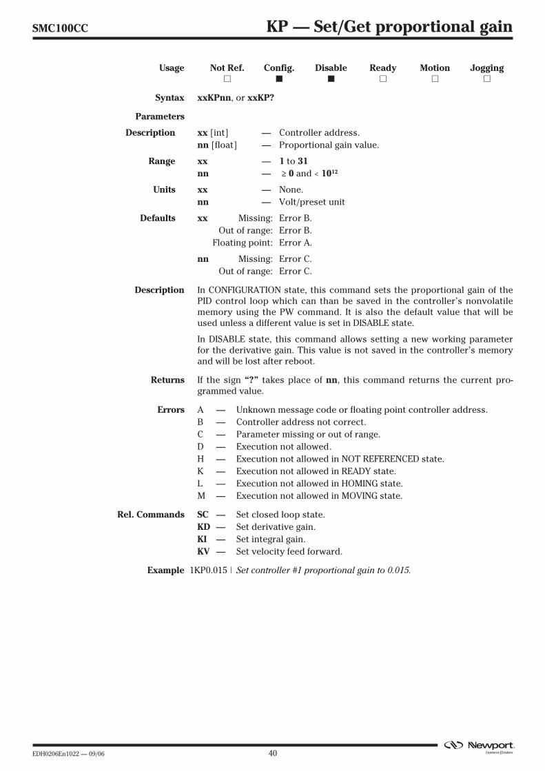
SMC100CC KP — Set/Get proportional gain
Usage Not Ref. Config. Disable Ready Motion Jogging� � � � � �
Syntax xxKPnn, or xxKP?
Parameters
Description xx [int] — Controller address.nn [float] — Proportional gain value.
Range xx — 1 to 31nn — ≥ 0 and < 1012
Units xx — None.nn — Volt/preset unit
Defaults xx Missing: Error B.Out of range: Error B.
Floating point: Error A.
nn Missing: Error C.Out of range: Error C.
Description In CONFIGURATION state, this command sets the proportional gain of thePID control loop which can than be saved in the controller’s nonvolatilememory using the PW command. It is also the default value that will beused unless a different value is set in DISABLE state.
In DISABLE state, this command allows setting a new working parameterfor the derivative gain. This value is not saved in the controller’s memoryand will be lost after reboot.
Returns If the sign “?” takes place of nn, this command returns the current pro-grammed value.
Errors A — Unknown message code or floating point controller address.B — Controller address not correct.C — Parameter missing or out of range.D — Execution not allowed.H — Execution not allowed in NOT REFERENCED state.K — Execution not allowed in READY state.L — Execution not allowed in HOMING state.M — Execution not allowed in MOVING state.
Rel. Commands SC — Set closed loop state.KD — Set derivative gain.KI — Set integral gain.KV — Set velocity feed forward.
Example 1KP0.015 | Set controller #1 proportional gain to 0.015.
41 EDH0206En1022 — 09/06
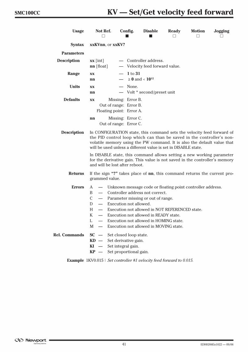
SMC100CC KV — Set/Get velocity feed forward
Usage Not Ref. Config. Disable Ready Motion Jogging� � � � � �
Syntax xxKVnn, or xxKV?
Parameters
Description xx [int] — Controller address.nn [float] — Velocity feed forward value.
Range xx — 1 to 31nn — ≥ 0 and < 1012
Units xx — None.nn — Volt * second/preset unit
Defaults xx Missing: Error B.Out of range: Error B.
Floating point: Error A.
nn Missing: Error C.Out of range: Error C.
Description In CONFIGURATION state, this command sets the velocity feed forward ofthe PID control loop which can than be saved in the controller’s non-volatile memory using the PW command. It is also the default value thatwill be used unless a different value is set in DISABLE state.
In DISABLE state, this command allows setting a new working parameterfor the derivative gain. This value is not saved in the controller’s memoryand will be lost after reboot.
Returns If the sign “?” takes place of nn, this command returns the current pro-grammed value.
Errors A — Unknown message code or floating point controller address.B — Controller address not correct.C — Parameter missing or out of range.D — Execution not allowed.H — Execution not allowed in NOT REFERENCED state.K — Execution not allowed in READY state.L — Execution not allowed in HOMING state.M — Execution not allowed in MOVING state.
Rel. Commands SC — Set closed loop state.KD — Set derivative gain.KI — Set integral gain.KP — Set proportional gain.
Example 1KV0.015 | Set controller #1 velocity feed forward to 0.015.

EDH0206En1022 — 09/06 42
SMC100CC MM — Enter/Leave DISABLE state
Usage Not Ref. Config. Disable Ready Motion Jogging� � � � � �
Syntax [xx]MMnn, or xxMM?
Parameters
Description xx [int] — Controller address.nn [float] — Velocity feed forward value.
Range xx — 0 to 31nn — 0 changes state from READY to DISABLE.
1 changes state from DISABLE to READY.
Units xx — None.nn — None.
Defaults xx Missing: Change to 0.Out of range: Error B.
Floating point: Error A.
nn Missing: Error C.Out of range: Error C.
Description When the MM command is sent without preceding controller number orthe controller number is 0, the MM command gets executed on all con-trollers.
MM0 changes the controller’s state from READY to DISABLE. In DISABLEstate the control loop is open and the motor is not energized. The encoder,though, is still read and the current position gets updated.
MM1 changes the controller’s state from DISABLE to READY. The con-troller’s set point position is set equal to its current position and the con-trol loop gets closed (depending on the closed-loop state). The residual fol-lowing error gets cleared from the buffer and the motor gets energized.
Returns If the sign “?” takes place of nn, this command returns the current state.
Errors A — Unknown message code or floating point controller address.B — Controller address not correct.C — Parameter missing or out of range.D — Execution not allowed.H — Execution not allowed in NOT REFERENCED state.I — Execution not allowed in CONFIGURATION state.L — Execution not allowed in HOMING state.M — Execution not allowed in MOVING state.
Rel. Commands PW — Enter/leave CONFIGURATION state.
Example MM0 | All controllers go to DISABLE state.
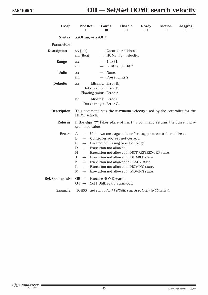
43 EDH0206En1022 — 09/06
SMC100CC OH — Set/Get HOME search velocity
Usage Not Ref. Config. Disable Ready Motion Jogging� � � � � �
Syntax xxOHnn, or xxOH?
Parameters
Description xx [int] — Controller address.nn [float] — HOME high velocity.
Range xx — 1 to 31nn — > 10-6 and < 1012
Units xx — None.nn — Preset units/s.
Defaults xx Missing: Error B.Out of range: Error B.
Floating point: Error A.
nn Missing: Error C.Out of range: Error C.
Description This command sets the maximum velocity used by the controller for theHOME search.
Returns If the sign “?” takes place of nn, this command returns the current pro-grammed value.
Errors A — Unknown message code or floating point controller address.B — Controller address not correct.C — Parameter missing or out of range.D — Execution not allowed.H — Execution not allowed in NOT REFERENCED state.J — Execution not allowed in DISABLE state.K — Execution not allowed in READY state.L — Execution not allowed in HOMING state.M — Execution not allowed in MOVING state.
Rel. Commands OR — Execute HOME search.OT — Set HOME search time-out.
Example 1OH50 | Set controller #1 HOME search velocity to 50 units/s.

EDH0206En1022 — 09/06 44
SMC100CC OR — Execute HOME search
Usage Not Ref. Config. Disable Ready Motion Jogging� � � � � �
Syntax xxOR
Parameters
Description xx [int] — Controller address.
Range xx — 1 to 31
Units xx — None.
Defaults xx Missing: Error B.Out of range: Error B.
Floating point: Error A.
nn Missing: Error C.Out of range: Error C.
Description This command starts the execution of the HOME search as defined by theHT command.
When in NOT REFERENCED state, for instance after system start, any posi-tioner must first get homed with the OR command before further motioncommands can get executed.
The OR command gets accepted only in NOT REFERENCED state and onlywith no present hardware errors, except for end-of-run maybe. Refer to theTS command to get more information on the possible hardware errors.
Errors A — Unknown message code or floating point controller address.B — Controller address not correct.C — Parameter missing or out of range.D — Execution not allowed.E — home sequence already started.I — Execution not allowed in CONFIGURATION state.J — Execution not allowed in DISABLE state.K — Execution not allowed in READY state.L — Execution not allowed in HOMING state.M — Execution not allowed in MOVING state.
Rel. Commands HT — Set HOME search type.OH — Set HOME search velocity.OT — Set HOME search time-out.
Example 1OR | Execute HOME search with controller #1.

45 EDH0206En1022 — 09/06
SMC100CC OT — Set/Get HOME search time-out
Usage Not Ref. Config. Disable Ready Motion Jogging� � � � � �
Syntax xxOTnn, or xxOT?
Parameters
Description xx [int] — Controller address.nn [float] — HOME time-out.
Range xx — 1 to 31nn — > 1 and < 103
Units xx — None.nn — Seconds
Defaults xx Missing: Error B.Out of range: Error B.
Floating point: Error A.
nn Missing: Error C.Out of range: Error C.
Description This command sets the time-out value for the HOME search. When theHOME search does not finish successfully before this time elapses, theHOME search will be aborted and an error gets recorded.
Returns If the sign “?” takes place of nn, this command returns the current pro-grammed value.
Errors A — Unknown message code or floating point controller address.B — Controller address not correct.C — Parameter missing or out of range.D — Execution not allowed.H — Execution not allowed in NOT REFERENCED state.J — Execution not allowed in DISABLE state.K — Execution not allowed in READY state.L — Execution not allowed in HOMING state.M — Execution not allowed in MOVING state.
Rel. Commands HT — Set HOME search type.OH — Set HOME search velocity.OR — Execute HOME search.
Example 1OT2.2 | Set controller #1 HOME time-out to 2.2 seconds.
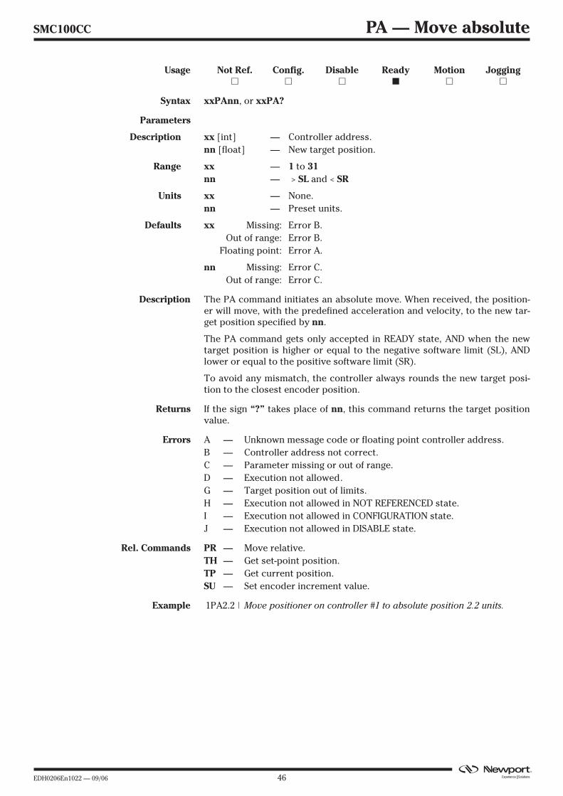
EDH0206En1022 — 09/06 46
SMC100CC PA — Move absolute
Usage Not Ref. Config. Disable Ready Motion Jogging� � � � � �
Syntax xxPAnn, or xxPA?
Parameters
Description xx [int] — Controller address.nn [float] — New target position.
Range xx — 1 to 31nn — > SL and < SR
Units xx — None.nn — Preset units.
Defaults xx Missing: Error B.Out of range: Error B.
Floating point: Error A.
nn Missing: Error C.Out of range: Error C.
Description The PA command initiates an absolute move. When received, the position-er will move, with the predefined acceleration and velocity, to the new tar-get position specified by nn.
The PA command gets only accepted in READY state, AND when the newtarget position is higher or equal to the negative software limit (SL), ANDlower or equal to the positive software limit (SR).
To avoid any mismatch, the controller always rounds the new target posi-tion to the closest encoder position.
Returns If the sign “?” takes place of nn, this command returns the target positionvalue.
Errors A — Unknown message code or floating point controller address.B — Controller address not correct.C — Parameter missing or out of range.D — Execution not allowed.G — Target position out of limits.H — Execution not allowed in NOT REFERENCED state.I — Execution not allowed in CONFIGURATION state.J — Execution not allowed in DISABLE state.
Rel. Commands PR — Move relative.TH — Get set-point position.TP — Get current position.SU — Set encoder increment value.
Example 1PA2.2 | Move positioner on controller #1 to absolute position 2.2 units.

47 EDH0206En1022 — 09/06
SMC100CC PR — Move relative
Usage Not Ref. Config. Disable Ready Motion Jogging� � � � � �
Syntax xxPRnn, or xxPR?
Parameters
Description xx [int] — Controller address.nn [float] — Displacement.
Range xx — 1 to 31nn — > SL and < SR
Units xx — None.nn — Preset units.
Defaults xx Missing: Error B.Out of range: Error B.
Floating point: Error A.
nn Missing: Error C.Out of range: Error C.
Description The PR command initiates a relative move. When received, the positionerwill move, with the predefined acceleration and velocity, to a new targetposition nn units away from the current target position.
The PR command gets only accepted in READY state, AND when the dis-tance of the positioner to the end of runs is larger than the commandeddisplacement.
To avoid any mismatch, the controller always rounds the new target posi-tion to the closest encoder position.
Returns If the sign “?” takes place of nn, this command returns the target positionvalue.
Errors A — Unknown message code or floating point controller address.B — Controller address not correct.C — Parameter missing or out of range.D — Execution not allowed.G — Displacement out of limits.H — Execution not allowed in NOT REFERENCED state.I — Execution not allowed in CONFIGURATION state.J — Execution not allowed in DISABLE state.
Rel. Commands PA — Move absolute.TH — Get set-point position.TP — Get current position.SU — Set encoder increment value.
Example 1PR2.2 | Move positioner on controller #1 to a new position 2.2 units awayfrom the current target position.
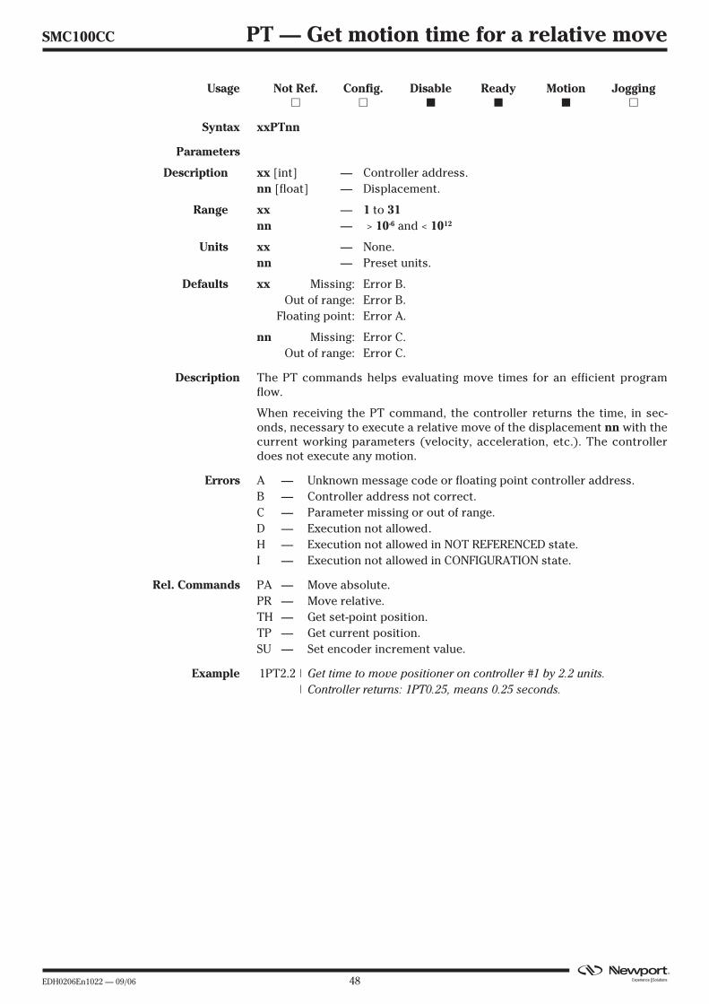
EDH0206En1022 — 09/06 48
SMC100CC PT — Get motion time for a relative move
Usage Not Ref. Config. Disable Ready Motion Jogging� � � � � �
Syntax xxPTnn
Parameters
Description xx [int] — Controller address.nn [float] — Displacement.
Range xx — 1 to 31nn — > 10-6 and < 1012
Units xx — None.nn — Preset units.
Defaults xx Missing: Error B.Out of range: Error B.
Floating point: Error A.
nn Missing: Error C.Out of range: Error C.
Description The PT commands helps evaluating move times for an efficient programflow.
When receiving the PT command, the controller returns the time, in sec-onds, necessary to execute a relative move of the displacement nn with thecurrent working parameters (velocity, acceleration, etc.). The controllerdoes not execute any motion.
Errors A — Unknown message code or floating point controller address.B — Controller address not correct.C — Parameter missing or out of range.D — Execution not allowed.H — Execution not allowed in NOT REFERENCED state.I — Execution not allowed in CONFIGURATION state.
Rel. Commands PA — Move absolute.PR — Move relative.TH — Get set-point position.TP — Get current position.SU — Set encoder increment value.
Example 1PT2.2 | Get time to move positioner on controller #1 by 2.2 units.| Controller returns: 1PT0.25, means 0.25 seconds.
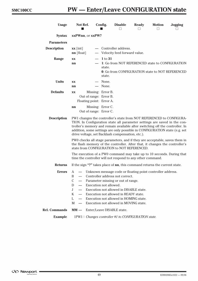
49 EDH0206En1022 — 09/06
SMC100CC PW — Enter/Leave CONFIGURATION state
Usage Not Ref. Config. Disable Ready Motion Jogging� � � � � �
Syntax xxPWnn, or xxPW?
Parameters
Description xx [int] — Controller address.nn [float] — Velocity feed forward value.
Range xx — 1 to 31nn — 1: Go from NOT REFERENCED state to CONFIGURATION
state.0: Go from CONFIGURATION state to NOT REFERENCEDstate.
Units xx — None.nn — None.
Defaults xx Missing: Error B.Out of range: Error B.
Floating point: Error A.
nn Missing: Error C.Out of range: Error C.
Description PW1 changes the controller’s state from NOT REFERENCED to CONFIGURA-TION. In Configuration state all parameter settings are saved in the con-troller’s memory and remain available after switching off the controller. Inaddition, some settings are only possible in CONFIGURATION state (e.g. setdrive voltage, set Backlash compensation, etc.).
PW0 checks all stage parameters, and if they are acceptable, saves them inthe flash memory of the controller. After that, it changes the controller’sstate from CONFIGURATION to NOT REFERENCED.
The execution of a PW0 command may take up to 10 seconds. During thattime the controller will not respond to any other command.
Returns If the sign “?” takes place of nn, this command returns the current state.
Errors A — Unknown message code or floating point controller address.B — Controller address not correct.C — Parameter missing or out of range.D — Execution not allowed.J — Execution not allowed in DISABLE state.K — Execution not allowed in READY state.L — Execution not allowed in HOMING state.M — Execution not allowed in MOVING state.
Rel. Commands MM — Enter/Leave DISABLE state.
Example 1PW1 | Changes controller #1 to CONFIGURATION state.
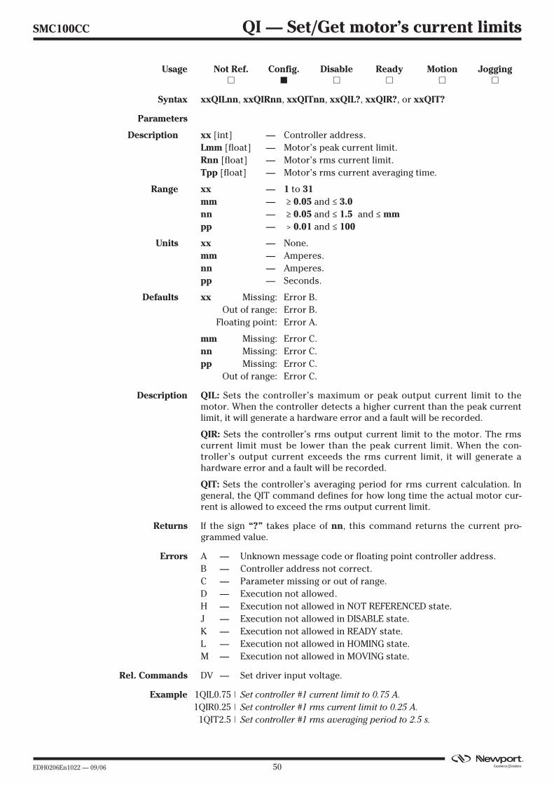
EDH0206En1022 — 09/06 50
SMC100CC QI — Set/Get motor’s current limits
Usage Not Ref. Config. Disable Ready Motion Jogging� � � � � �
Syntax xxQILnn, xxQIRnn, xxQITnn, xxQIL?, xxQIR?, or xxQIT?
Parameters
Description xx [int] — Controller address.Lmm [float] — Motor’s peak current limit.Rnn [float] — Motor’s rms current limit.Tpp [float] — Motor’s rms current averaging time.
Range xx — 1 to 31mm — ≥ 0.05 and ≤ 3.0nn — ≥ 0.05 and ≤ 1.5 and ≤ mmpp — > 0.01 and ≤ 100
Units xx — None.mm — Amperes.nn — Amperes.pp — Seconds.
Defaults xx Missing: Error B.Out of range: Error B.
Floating point: Error A.
mm Missing: Error C.nn Missing: Error C.pp Missing: Error C.
Out of range: Error C.
Description QIL: Sets the controller’s maximum or peak output current limit to themotor. When the controller detects a higher current than the peak currentlimit, it will generate a hardware error and a fault will be recorded.
QIR: Sets the controller’s rms output current limit to the motor. The rmscurrent limit must be lower than the peak current limit. When the con-troller’s output current exceeds the rms current limit, it will generate ahardware error and a fault will be recorded.
QIT: Sets the controller’s averaging period for rms current calculation. Ingeneral, the QIT command defines for how long time the actual motor cur-rent is allowed to exceed the rms output current limit.
Returns If the sign “?” takes place of nn, this command returns the current pro-grammed value.
Errors A — Unknown message code or floating point controller address.B — Controller address not correct.C — Parameter missing or out of range.D — Execution not allowed.H — Execution not allowed in NOT REFERENCED state.J — Execution not allowed in DISABLE state.K — Execution not allowed in READY state.L — Execution not allowed in HOMING state.M — Execution not allowed in MOVING state.
Rel. Commands DV — Set driver input voltage.
Example 1QIL0.75 | Set controller #1 current limit to 0.75 A.1QIR0.25 | Set controller #1 rms current limit to 0.25 A.1QIT2.5 | Set controller #1 rms averaging period to 2.5 s.

51 EDH0206En1022 — 09/06
SMC100CC RA — Get analog input value
Usage Not Ref. Config. Disable Ready Motion Jogging� � � � � �
Syntax xxRA
Parameters
Description xx [int] — Controller address.
Range xx — 1 to 31
Units xx — None.
Defaults xx Missing: Error B.Out of range: Error B.
Floating point: Error A.
Description The RA command returns the value of the ±10 volts analog input. The con-verter is a ±7 bits analog to digital converter with ±0.15 volts of maximumoffset and 5% full scale linearity. The resolution is 0.078125 volts.
Errors A — Unknown message code or floating point controller address.B — Controller address not correct.D — Execution not allowed.H — Execution not allowed in NOT REFERENCED state.I — Execution not allowed in CONFIGURATION state.
Rel. Commands SB — Get TTL inputs.
Example 1RA | Get controller axis #1 analog input.| Controller returns: 1RA7.8125, means 7.8125 V.

EDH0206En1022 — 09/06 52
SMC100CC RB — Get TTL input value
Usage Not Ref. Config. Disable Ready Motion Jogging� � � � � �
Syntax xxRB
Parameters
Description xx [int] — Controller address.
Range xx — 1 to 31
Units xx — None.
Defaults xx Missing: Error B.Out of range: Error B.
Floating point: Error A.
Description The RB command returns the value of the TTL inputs. The returned deci-mal number represents the binary word made of all 4 inputs, where bit 0 isinput 1, bit 1 is input 2, bit 2 is input 3, and bit 3 is input 4.
The TTL input value is 1 when the corresponding voltage on the pin is larg-er than 2.4 volts, and it is 0 when the corresponding voltage is below 0.8volt. When the voltage is between these two values, the result is unreliableand can be 1 or 0.
Errors A — Unknown message code or floating point controller address.B — Controller address not correct.D — Execution not allowed.H — Execution not allowed in NOT REFERENCED state.I — Execution not allowed in CONFIGURATION state.
Rel. Commands RA — Get analog input value.
Example 1RB | Get TTL input value for controller #1.| Controller returns: 1RB5, means input 0 and 2 are high, all others
are low.
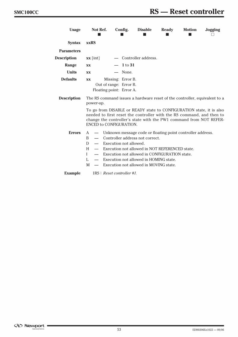
53 EDH0206En1022 — 09/06
SMC100CC RS — Reset controller
Usage Not Ref. Config. Disable Ready Motion Jogging� � � � � �
Syntax xxRS
Parameters
Description xx [int] — Controller address.
Range xx — 1 to 31
Units xx — None.
Defaults xx Missing: Error B.Out of range: Error B.
Floating point: Error A.
Description The RS command issues a hardware reset of the controller, equivalent to apower-up.
To go from DISABLE or READY state to CONFIGURATION state, it is alsoneeded to first reset the controller with the RS command, and then tochange the controller’s state with the PW1 command from NOT REFER-ENCED to CONFIGURATION.
Errors A — Unknown message code or floating point controller address.B — Controller address not correct.D — Execution not allowed.H — Execution not allowed in NOT REFERENCED state.I — Execution not allowed in CONFIGURATION state.L — Execution not allowed in HOMING state.M — Execution not allowed in MOVING state.
Example 1RS | Reset controller #1.
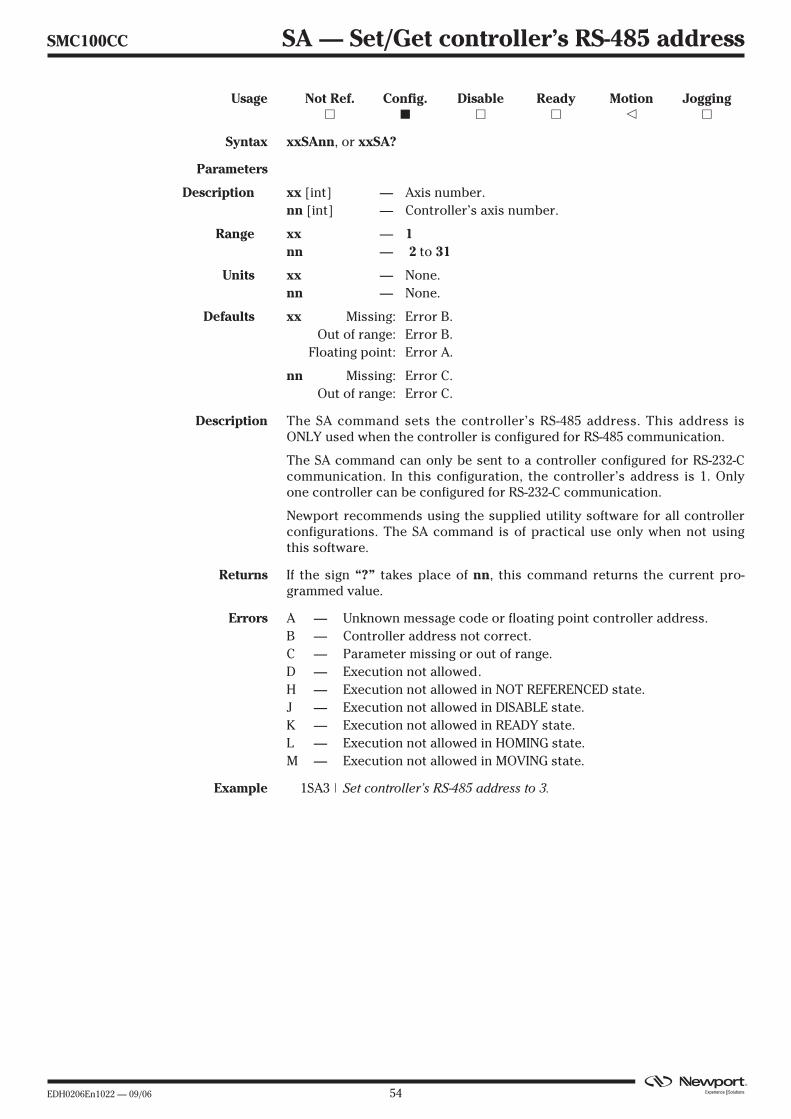
EDH0206En1022 — 09/06 54
SMC100CC SA — Set/Get controller’s RS-485 address
Usage Not Ref. Config. Disable Ready Motion Jogging� � � � � �
Syntax xxSAnn, or xxSA?
Parameters
Description xx [int] — Axis number.nn [int] — Controller’s axis number.
Range xx — 1nn — 2 to 31
Units xx — None.nn — None.
Defaults xx Missing: Error B.Out of range: Error B.
Floating point: Error A.
nn Missing: Error C.Out of range: Error C.
Description The SA command sets the controller’s RS-485 address. This address isONLY used when the controller is configured for RS-485 communication.
The SA command can only be sent to a controller configured for RS-232-Ccommunication. In this configuration, the controller’s address is 1. Onlyone controller can be configured for RS-232-C communication.
Newport recommends using the supplied utility software for all controllerconfigurations. The SA command is of practical use only when not usingthis software.
Returns If the sign “?” takes place of nn, this command returns the current pro-grammed value.
Errors A — Unknown message code or floating point controller address.B — Controller address not correct.C — Parameter missing or out of range.D — Execution not allowed.H — Execution not allowed in NOT REFERENCED state.J — Execution not allowed in DISABLE state.K — Execution not allowed in READY state.L — Execution not allowed in HOMING state.M — Execution not allowed in MOVING state.
Example 1SA3 | Set controller’s RS-485 address to 3.
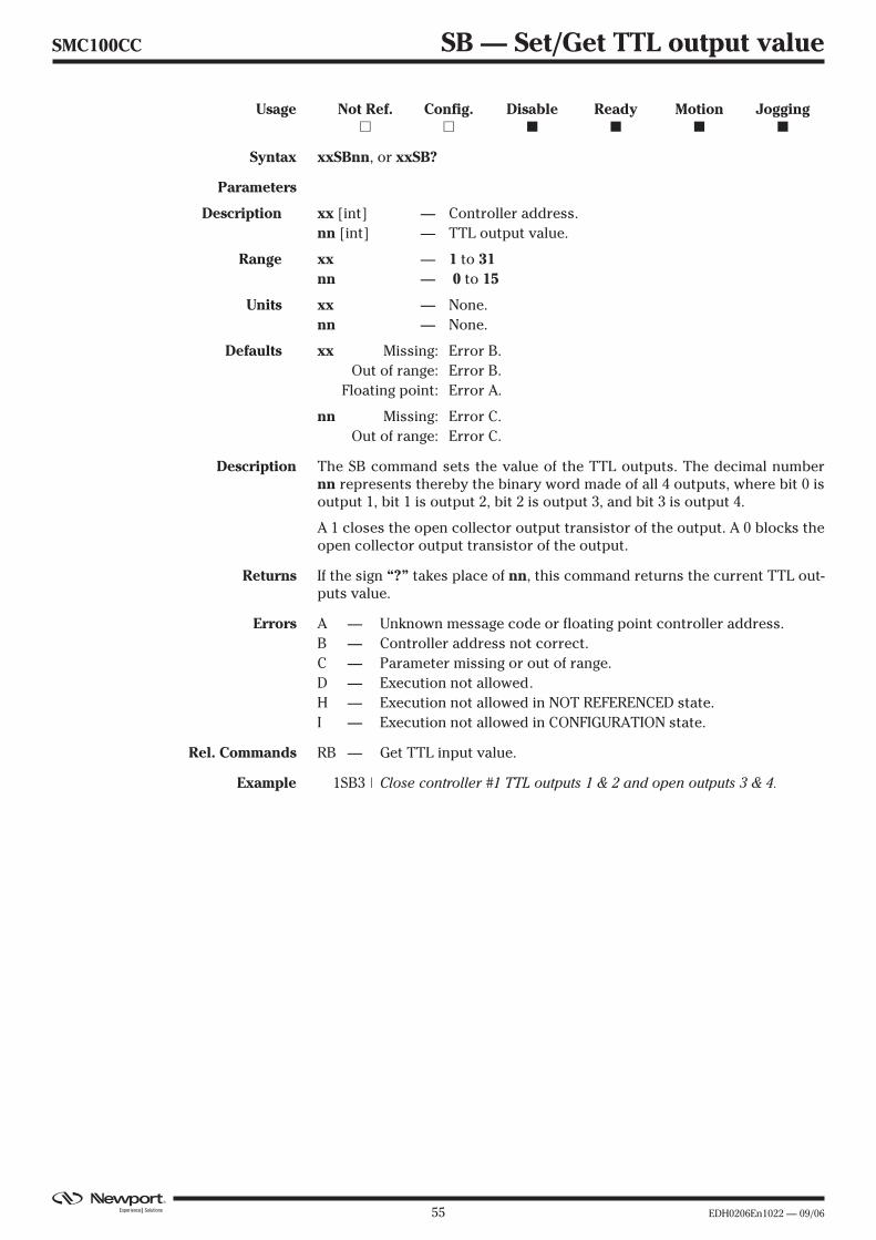
55 EDH0206En1022 — 09/06
SMC100CC SB — Set/Get TTL output value
Usage Not Ref. Config. Disable Ready Motion Jogging� � � � � �
Syntax xxSBnn, or xxSB?
Parameters
Description xx [int] — Controller address.nn [int] — TTL output value.
Range xx — 1 to 31nn — 0 to 15
Units xx — None.nn — None.
Defaults xx Missing: Error B.Out of range: Error B.
Floating point: Error A.
nn Missing: Error C.Out of range: Error C.
Description The SB command sets the value of the TTL outputs. The decimal numbernn represents thereby the binary word made of all 4 outputs, where bit 0 isoutput 1, bit 1 is output 2, bit 2 is output 3, and bit 3 is output 4.
A 1 closes the open collector output transistor of the output. A 0 blocks theopen collector output transistor of the output.
Returns If the sign “?” takes place of nn, this command returns the current TTL out-puts value.
Errors A — Unknown message code or floating point controller address.B — Controller address not correct.C — Parameter missing or out of range.D — Execution not allowed.H — Execution not allowed in NOT REFERENCED state.I — Execution not allowed in CONFIGURATION state.
Rel. Commands RB — Get TTL input value.
Example 1SB3 | Close controller #1 TTL outputs 1 & 2 and open outputs 3 & 4.
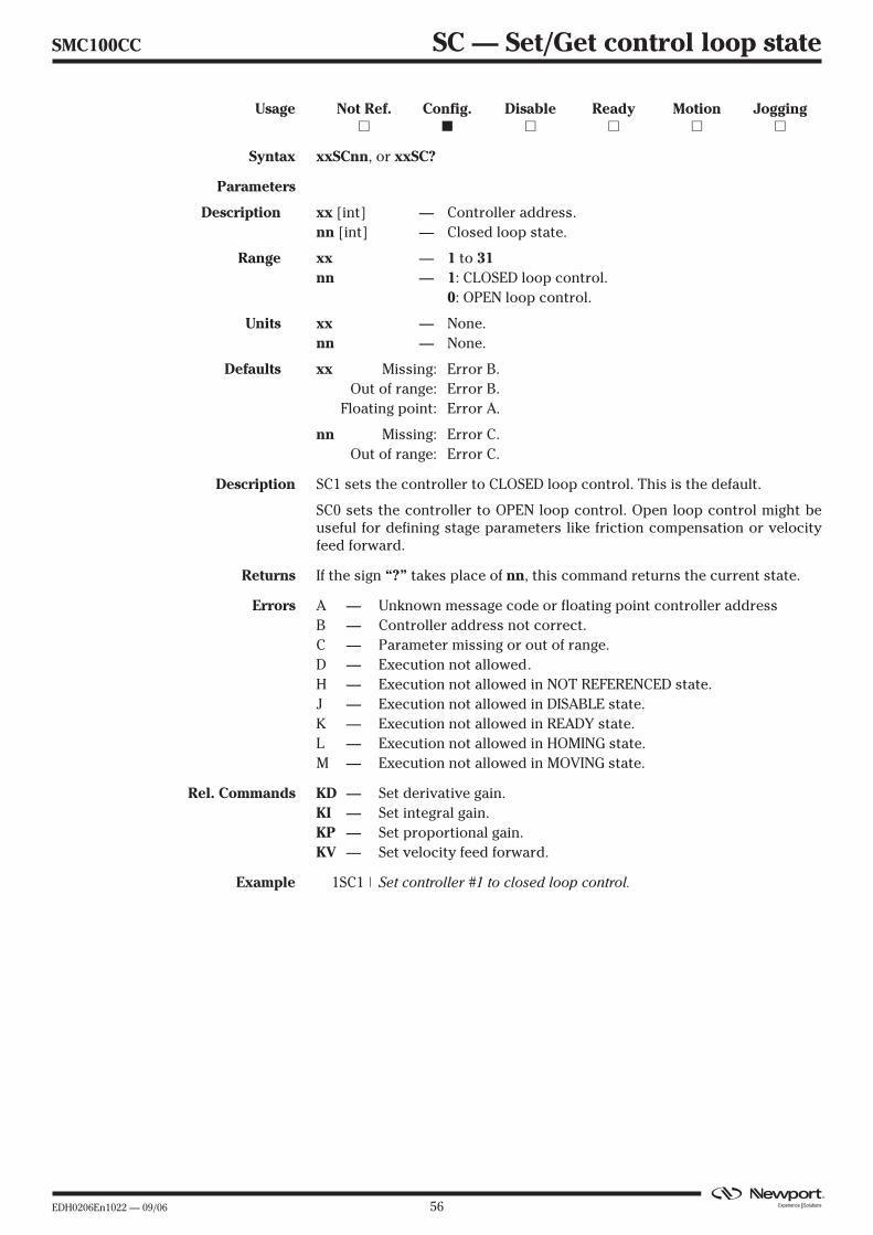
EDH0206En1022 — 09/06 56
SMC100CC SC — Set/Get control loop state
Usage Not Ref. Config. Disable Ready Motion Jogging� � � � � �
Syntax xxSCnn, or xxSC?
Parameters
Description xx [int] — Controller address.nn [int] — Closed loop state.
Range xx — 1 to 31nn — 1: CLOSED loop control.
0: OPEN loop control.
Units xx — None.nn — None.
Defaults xx Missing: Error B.Out of range: Error B.
Floating point: Error A.
nn Missing: Error C.Out of range: Error C.
Description SC1 sets the controller to CLOSED loop control. This is the default.
SC0 sets the controller to OPEN loop control. Open loop control might beuseful for defining stage parameters like friction compensation or velocityfeed forward.
Returns If the sign “?” takes place of nn, this command returns the current state.
Errors A — Unknown message code or floating point controller addressB — Controller address not correct.C — Parameter missing or out of range.D — Execution not allowed.H — Execution not allowed in NOT REFERENCED state.J — Execution not allowed in DISABLE state.K — Execution not allowed in READY state.L — Execution not allowed in HOMING state.M — Execution not allowed in MOVING state.
Rel. Commands KD — Set derivative gain.KI — Set integral gain.KP — Set proportional gain.KV — Set velocity feed forward.
Example 1SC1 | Set controller #1 to closed loop control.
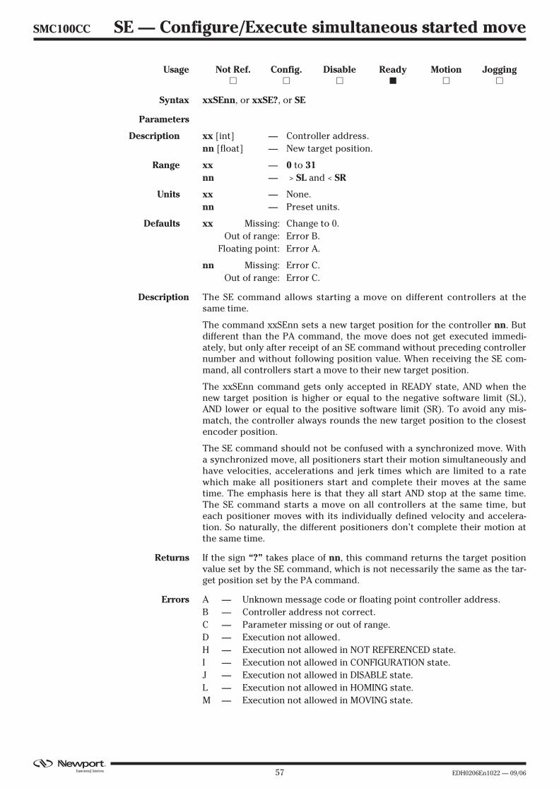
57 EDH0206En1022 — 09/06
SMC100CC SE — Configure/Execute simultaneous started move
Usage Not Ref. Config. Disable Ready Motion Jogging� � � � � �
Syntax xxSEnn, or xxSE?, or SE
Parameters
Description xx [int] — Controller address.nn [float] — New target position.
Range xx — 0 to 31nn — > SL and < SR
Units xx — None.nn — Preset units.
Defaults xx Missing: Change to 0.Out of range: Error B.
Floating point: Error A.
nn Missing: Error C.Out of range: Error C.
Description The SE command allows starting a move on different controllers at thesame time.
The command xxSEnn sets a new target position for the controller nn. Butdifferent than the PA command, the move does not get executed immedi-ately, but only after receipt of an SE command without preceding controllernumber and without following position value. When receiving the SE com-mand, all controllers start a move to their new target position.
The xxSEnn command gets only accepted in READY state, AND when thenew target position is higher or equal to the negative software limit (SL),AND lower or equal to the positive software limit (SR). To avoid any mis-match, the controller always rounds the new target position to the closestencoder position.
The SE command should not be confused with a synchronized move. Witha synchronized move, all positioners start their motion simultaneously andhave velocities, accelerations and jerk times which are limited to a ratewhich make all positioners start and complete their moves at the sametime. The emphasis here is that they all start AND stop at the same time.The SE command starts a move on all controllers at the same time, buteach positioner moves with its individually defined velocity and accelera-tion. So naturally, the different positioners don’t complete their motion atthe same time.
Returns If the sign “?” takes place of nn, this command returns the target positionvalue set by the SE command, which is not necessarily the same as the tar-get position set by the PA command.
Errors A — Unknown message code or floating point controller address.B — Controller address not correct.C — Parameter missing or out of range.D — Execution not allowed.H — Execution not allowed in NOT REFERENCED state.I — Execution not allowed in CONFIGURATION state.J — Execution not allowed in DISABLE state.L — Execution not allowed in HOMING state.M — Execution not allowed in MOVING state.
EDH0206En1022 — 09/06 58
Rel. Commands PR — Move relative.TH — Get set-point position.TP — Get current position.SU — Set encoder increment value.
Example 1SE2.2 | Prepare controller #1 to move to absolute position 2.2 units.2SE3.3 | Prepare controller #2 to move to absolute position 3.3 units.
SE | All controllers start their programmed move, if any.
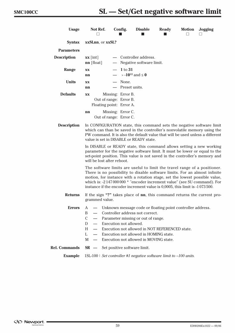
59 EDH0206En1022 — 09/06
SMC100CC SL — Set/Get negative software limit
Usage Not Ref. Config. Disable Ready Motion Jogging� � � � � �
Syntax xxSLnn, or xxSL?
Parameters
Description xx [int] — Controller address.nn [float] — Negative software limit.
Range xx — 1 to 31nn — > -1012 and ≤ 0
Units xx — None.nn — Preset units.
Defaults xx Missing: Error B.Out of range: Error B.
Floating point: Error A.
nn Missing: Error C.Out of range: Error C.
Description In CONFIGURATION state, this command sets the negative software limitwhich can than be saved in the controller’s nonvolatile memory using thePW command. It is also the default value that will be used unless a differentvalue is set in DISABLE or READY state.
In DISABLE or READY state, this command allows setting a new workingparameter for the negative software limit. It must be lower or equal to theset-point position. This value is not saved in the controller’s memory andwill be lost after reboot.
The software limits are useful to limit the travel range of a positioner.There is no possibility to disable software limits. For an almost infinitemotion, for instance with a rotation stage, set the lowest possible value,which is: -2 147 000 000 * "encoder increment value" (see SU command). Forinstance if the encoder increment value is 0,0005, this limit is -1 073 500.
Returns If the sign “?” takes place of nn, this command returns the current pro-grammed value.
Errors A — Unknown message code or floating point controller address.B — Controller address not correct.C — Parameter missing or out of range.D — Execution not allowed.H — Execution not allowed in NOT REFERENCED state.L — Execution not allowed in HOMING state.M — Execution not allowed in MOVING state.
Rel. Commands SR — Set positive software limit.
Example 1SL-100 | Set controller #1 negative software limit to –100 units.

EDH0206En1022 — 09/06 60
SMC100CC SR — Set/Get positive software limit
Usage Not Ref. Config. Disable Ready Motion Jogging� � � � � �
Syntax xxSRnn, or xxSR?
Parameters
Description xx [int] — Controller address.nn [float] — Positive software limit.
Range xx — 1 to 31nn — ≥ 0 and < 1012
Units xx — None.nn — Preset units.
Defaults xx Missing: Error B.Out of range: Error B.
Floating point: Error A.
nn Missing: Error C.Out of range: Error C.
Description In CONFIGURATION state, this command sets the positive software limitwhich can than be saved in the controller’s nonvolatile memory using thePW command. It is also the default value that will be used unless a differentvalue is set in DISABLE or READY state.
In DISABLE or READY state, this command allows setting a new workingparameter for the positive software limit. It must be larger or equal to theset-point position. This value is not saved in the controller’s memory andwill be lost after reboot.
The software limits are useful to limit the travel range of a positioner.There is no possibility to disable software limits. For an almost infinitemotion, for instance with a rotation stage, set the largest possible value,which is: 2 147 000 000 * "encoder increment value" (see SU command). Forinstance if the encoder increment value is 0,0005, this limit is 1 073 500.
Returns If the sign “?” takes place of nn, this command returns the current pro-grammed value.
Errors A — Unknown message code or floating point controller address.B — Controller address not correct.C — Parameter missing or out of range.D — Execution not allowed.H — Execution not allowed in NOT REFERENCED state.L — Execution not allowed in HOMING state.M — Execution not allowed in MOVING state.
Rel. Commands SL — Set negative software limit.
Example 1SR100 | Set controller #1 positive software positive to 100 units.
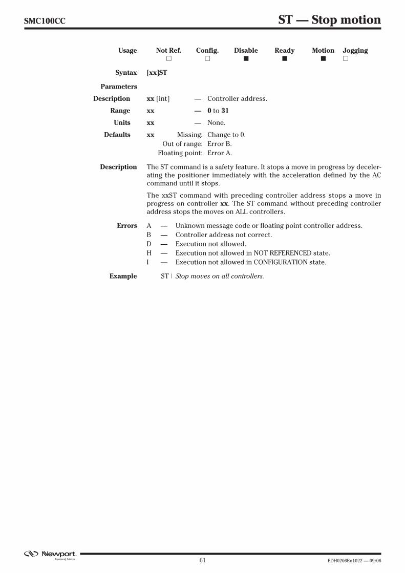
61 EDH0206En1022 — 09/06
SMC100CC ST — Stop motion
Usage Not Ref. Config. Disable Ready Motion Jogging� � � � � �
Syntax [xx]ST
Parameters
Description xx [int] — Controller address.
Range xx — 0 to 31
Units xx — None.
Defaults xx Missing: Change to 0.Out of range: Error B.
Floating point: Error A.
Description The ST command is a safety feature. It stops a move in progress by deceler-ating the positioner immediately with the acceleration defined by the ACcommand until it stops.
The xxST command with preceding controller address stops a move inprogress on controller xx. The ST command without preceding controlleraddress stops the moves on ALL controllers.
Errors A — Unknown message code or floating point controller address.B — Controller address not correct.D — Execution not allowed.H — Execution not allowed in NOT REFERENCED state.I — Execution not allowed in CONFIGURATION state.
Example ST | Stop moves on all controllers.
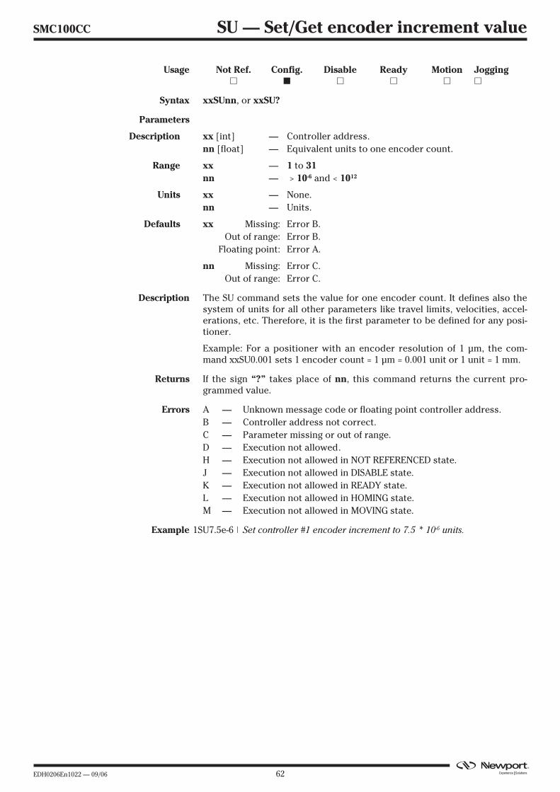
EDH0206En1022 — 09/06 62
SMC100CC SU — Set/Get encoder increment value
Usage Not Ref. Config. Disable Ready Motion Jogging� � � � � �
Syntax xxSUnn, or xxSU?
Parameters
Description xx [int] — Controller address.nn [float] — Equivalent units to one encoder count.
Range xx — 1 to 31nn — > 10-6 and < 1012
Units xx — None.nn — Units.
Defaults xx Missing: Error B.Out of range: Error B.
Floating point: Error A.
nn Missing: Error C.Out of range: Error C.
Description The SU command sets the value for one encoder count. It defines also thesystem of units for all other parameters like travel limits, velocities, accel-erations, etc. Therefore, it is the first parameter to be defined for any posi-tioner.
Example: For a positioner with an encoder resolution of 1 µm, the com-mand xxSU0.001 sets 1 encoder count = 1 µm = 0.001 unit or 1 unit = 1 mm.
Returns If the sign “?” takes place of nn, this command returns the current pro-grammed value.
Errors A — Unknown message code or floating point controller address.B — Controller address not correct.C — Parameter missing or out of range.D — Execution not allowed.H — Execution not allowed in NOT REFERENCED state.J — Execution not allowed in DISABLE state.K — Execution not allowed in READY state.L — Execution not allowed in HOMING state.M — Execution not allowed in MOVING state.
Example 1SU7.5e-6 | Set controller #1 encoder increment to 7.5 * 10-6 units.
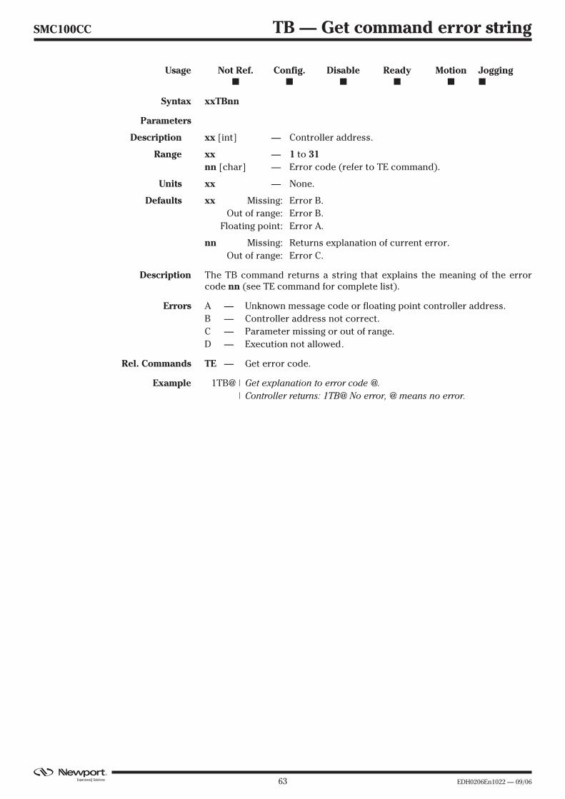
63 EDH0206En1022 — 09/06
SMC100CC TB — Get command error string
Usage Not Ref. Config. Disable Ready Motion Jogging� � � � � �
Syntax xxTBnn
Parameters
Description xx [int] — Controller address.
Range xx — 1 to 31nn [char] — Error code (refer to TE command).
Units xx — None.
Defaults xx Missing: Error B.Out of range: Error B.
Floating point: Error A.
nn Missing: Returns explanation of current error.Out of range: Error C.
Description The TB command returns a string that explains the meaning of the errorcode nn (see TE command for complete list).
Errors A — Unknown message code or floating point controller address.B — Controller address not correct.C — Parameter missing or out of range.D — Execution not allowed.
Rel. Commands TE — Get error code.
Example 1TB@ | Get explanation to error code @.| Controller returns: 1TB@ No error, @ means no error.

EDH0206En1022 — 09/06 64
SMC100CC TE — Get last command error
Usage Not Ref. Config. Disable Ready Motion Jogging� � � � � �
Syntax xxTE
Parameters
Description xx [int] — Controller address.
Range xx — 1 to 31
Units xx — None.
Defaults xx Missing: Error B.Out of range: Error B.
Floating point: Error A.
Description The TE command returns the currently memorized error. When a com-mand is not executable, it memorizes an error. This error can be read withthe TE command. After the execution of a TE command, the error buffergets erased and another TE command will return @, means no error. Whena new command error is generated before the previous command error isread, the new command error will overwrite the current memorized error.
For a safe program flow it is recommended to always query the commanderror after each command execution.
Errors A — Unknown message code or floating point controller address.B — Controller address not correct.D — Execution not allowed.
Rel. Commands TB — Get error string.
Example 1TE | Get last error memorized on controller #1.| Controller returns: 1TE@, means no error.
List of errors and corresponding strings (see TB command):@ — No error.A — Unknown message code or floating point controller address.B — Controller address not correct.C — Parameter missing or out of range.D — Command not allowed.E — Home sequence already started.F — ESP stage name unknown.G — Displacement out of limits.H — Command not allowed in NOT REFERENCED state.I — Command not allowed in CONFIGURATION state.J — Command not allowed in DISABLE state.K — Command not allowed in READY state.L — Command not allowed in HOMING state.M — Command not allowed in MOVING state.S — Communication Time Out.U — Error during EEPROM access.
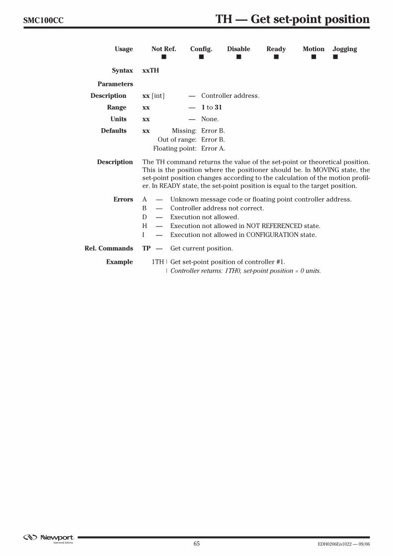
65 EDH0206En1022 — 09/06
SMC100CC TH — Get set-point position
Usage Not Ref. Config. Disable Ready Motion Jogging� � � � � �
Syntax xxTH
Parameters
Description xx [int] — Controller address.
Range xx — 1 to 31
Units xx — None.
Defaults xx Missing: Error B.Out of range: Error B.
Floating point: Error A.
Description The TH command returns the value of the set-point or theoretical position.This is the position where the positioner should be. In MOVING state, theset-point position changes according to the calculation of the motion profil-er. In READY state, the set-point position is equal to the target position.
Errors A — Unknown message code or floating point controller address.B — Controller address not correct.D — Execution not allowed.H — Execution not allowed in NOT REFERENCED state.I — Execution not allowed in CONFIGURATION state.
Rel. Commands TP — Get current position.
Example 1TH | Get set-point position of controller #1.| Controller returns: 1TH0, set-point position = 0 units.

EDH0206En1022 — 09/06 66
SMC100CC TP — Get current position
Usage Not Ref. Config. Disable Ready Motion Jogging� � � � � �
Syntax xxTP
Parameters
Description xx [int] — Controller address.
Range xx — 1 to 31
Units xx — None.
Defaults xx Missing: Error B.Out of range: Error B.
Floating point: Error A.
Description The TP command returns the value of the current position. This is the posi-tion where the positioner actually is according to his encoder value. InMOVING state, this value always changes. In READY state, this value shouldbe equal or very close to the set-point and target position.
Together with the TS command, the TP command helps evaluating whethera motion is completed.
Errors A — Unknown message code or floating point controller address.B — Controller address not correct.D — Execution not allowedH — Execution not allowed in NOT REFERENCED state.I — Execution not allowed in CONFIGURATION state.
Rel. Commands TH — Get set-point position.
Example 1TP | Get current position of controller #1.| Controller returns: 1TP0, actual position = 0 units.
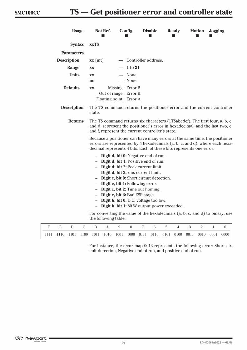
67 EDH0206En1022 — 09/06
SMC100CC TS — Get positioner error and controller state
Usage Not Ref. Config. Disable Ready Motion Jogging� � � � � �
Syntax xxTS
Parameters
Description xx [int] — Controller address.
Range xx — 1 to 31
Units xx — None.nn — None.
Defaults xx Missing: Error B.Out of range: Error B.
Floating point: Error A.
Description The TS command returns the positioner error and the current controllerstate.
Returns The TS command returns six characters (1TSabcdef). The first four, a, b, c,and d, represent the positioner’s error in hexadecimal, and the last two, e,and f, represent the current controller’s state.
Because a positioner can have many errors at the same time, the positionererrors are represented by 4 hexadecimals (a, b, c, and d), where each hexa-decimal represents 4 bits. Each of these bits represents one error:
– Digit d, bit 0: Negative end of run.– Digit d, bit 1: Positive end of run.– Digit d, bit 2: Peak current limit.– Digit d, bit 3: rms current limit.– Digit c, bit 0: Short circuit detection.– Digit c, bit 1: Following error.– Digit c, bit 2: Time out homing.– Digit c, bit 3: Bad ESP stage.– Digit b, bit 0: D.C. voltage too low.– Digit b, bit 1: 80 W output power exceeded.
For converting the value of the hexadecimals (a, b, c, and d) to binary, usethe following table:
For instance, the error map 0013 represents the following error: Short cir-cuit detection, Negative end of run, and positive end of run.
F E D C B A 9 8 7 6 5 4 3 2 1 0
1111 1110 1101 1100 1011 1010 1001 1000 0111 0110 0101 0100 0011 0010 0001 0000
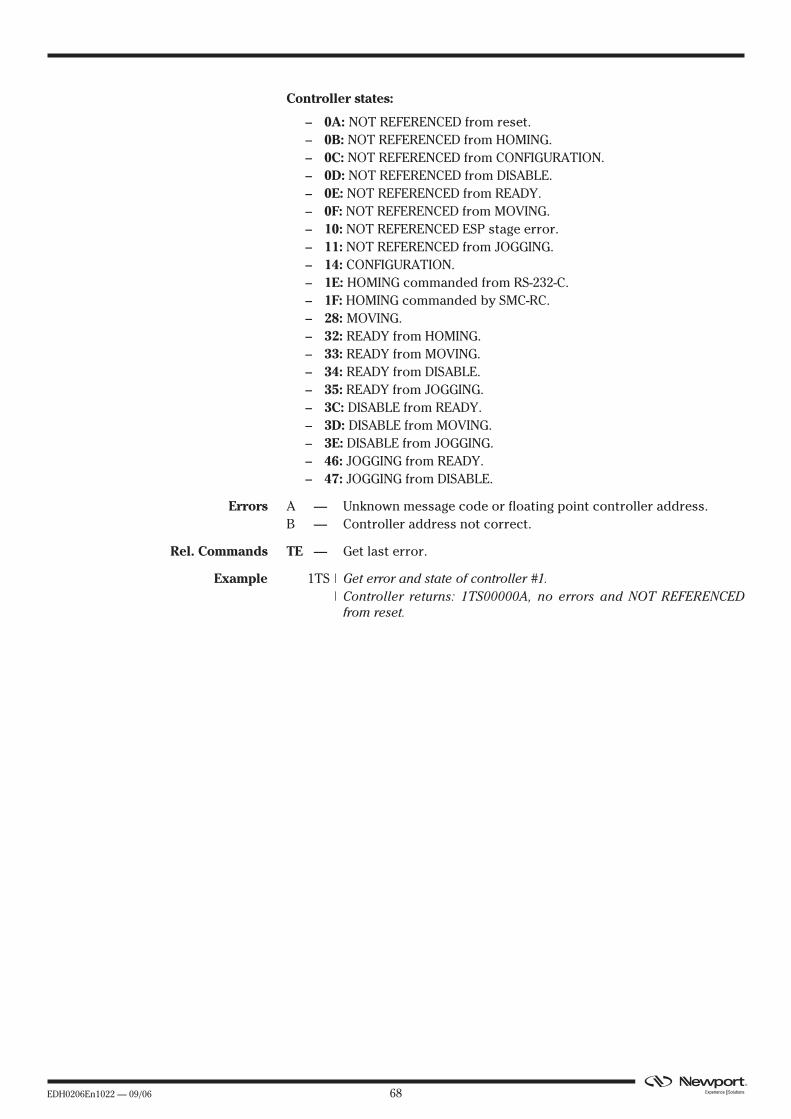
EDH0206En1022 — 09/06 68
Controller states:
– 0A: NOT REFERENCED from reset.– 0B: NOT REFERENCED from HOMING.– 0C: NOT REFERENCED from CONFIGURATION.– 0D: NOT REFERENCED from DISABLE.– 0E: NOT REFERENCED from READY.– 0F: NOT REFERENCED from MOVING.– 10: NOT REFERENCED ESP stage error.– 11: NOT REFERENCED from JOGGING.– 14: CONFIGURATION.– 1E: HOMING commanded from RS-232-C.– 1F: HOMING commanded by SMC-RC.– 28: MOVING.– 32: READY from HOMING.– 33: READY from MOVING.– 34: READY from DISABLE.– 35: READY from JOGGING.– 3C: DISABLE from READY.– 3D: DISABLE from MOVING.– 3E: DISABLE from JOGGING.– 46: JOGGING from READY.– 47: JOGGING from DISABLE.
Errors A — Unknown message code or floating point controller address.B — Controller address not correct.
Rel. Commands TE — Get last error.
Example 1TS | Get error and state of controller #1.| Controller returns: 1TS00000A, no errors and NOT REFERENCED
from reset.
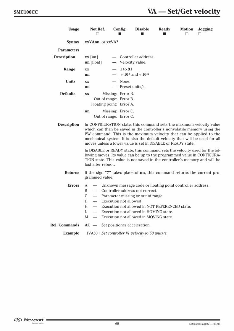
69 EDH0206En1022 — 09/06
SMC100CC VA — Set/Get velocity
Usage Not Ref. Config. Disable Ready Motion Jogging� � � � � �
Syntax xxVAnn, or xxVA?
Parameters
Description xx [int] — Controller address.nn [float] — Velocity value.
Range xx — 1 to 31nn — > 10-6 and < 1012
Units xx — None.nn — Preset units/s.
Defaults xx Missing: Error B.Out of range: Error B.
Floating point: Error A.
nn Missing: Error C.Out of range: Error C.
Description In CONFIGURATION state, this command sets the maximum velocity valuewhich can than be saved in the controller’s nonvolatile memory using thePW command. This is the maximum velocity that can be applied to themechanical system. It is also the default velocity that will be used for allmoves unless a lower value is set in DISABLE or READY state.
In DISABLE or READY state, this command sets the velocity used for the fol-lowing moves. Its value can be up to the programmed value in CONFIGURA-TION state. This value is not saved in the controller’s memory and will belost after reboot.
Returns If the sign “?” takes place of nn, this command returns the current pro-grammed value.
Errors A — Unknown message code or floating point controller address.B — Controller address not correct.C — Parameter missing or out of range.D — Execution not allowed.H — Execution not allowed in NOT REFERENCED state.L — Execution not allowed in HOMING state.M — Execution not allowed in MOVING state.
Rel. Commands AC — Set positioner acceleration.
Example 1VA50 | Set controller #1 velocity to 50 units/s.

EDH0206En1022 — 09/06 70
SMC100CC VE — Get controller revision information
Usage Not Ref. Config. Disable Ready Motion Jogging� � � � � �
Syntax xxVE
Parameters
Description xx [int] — Controller address.nn [string] — Action.
Range xx — 1 to 31
Units xx — None.
Defaults xx Missing: Error B.Out of range: Error B.
Floating point: Error A.
Description This command returns the controller’s revision information.
Errors A — Unknown message code or floating point controller address.B — Controller address not correct.
Rel. Commands TP — Get current position.
Example 1VE | Get controller #1 revision information.| Controller returns 1VE SMC - Controller-driver version 1.00r.

71 EDH0206En1022 — 09/06
SMC100CC ZT — Get all configuration parameters
Usage Not Ref. Config. Disable Ready Motion Jogging� � � � � �
Syntax xxZT
Parameters
Description xx [int] — Controller address.
Range xx — 1 to 31
Units xx — None.
Defaults xx Missing: Error B.Out of range: Error B.
Floating point: Error A.
Description The ZT command returns the list of all current configuration parameters.
The ZT command allows a quick review of all current stage parameter andsimplifies the configuration of non Newport stages, for instance by usingHyper Terminal file transfer.
Errors A — Unknown message code or floating point controller addressB — Controller address not correct
Rel. Commands TE — Get error code.
Example 1ZT | Get controller #1 configuration data.1PW1
1AC320.0000001BA0.000000
…1VA80.000000
1ZX31PW1
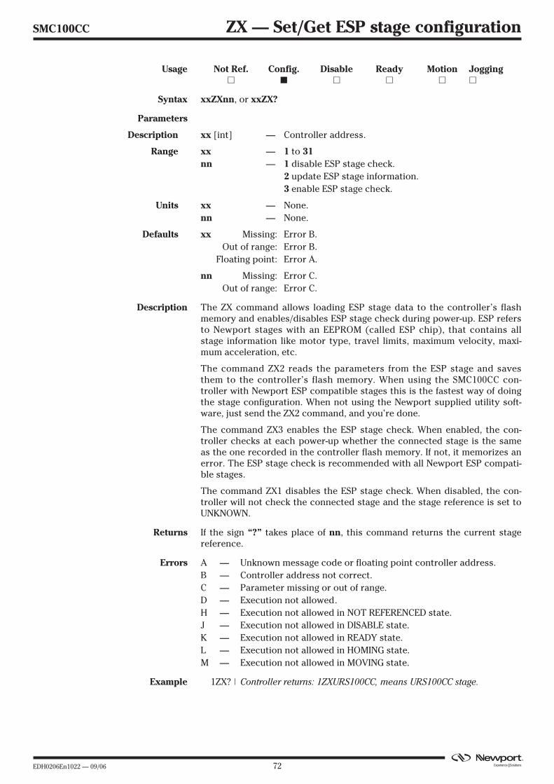
EDH0206En1022 — 09/06 72
SMC100CC ZX — Set/Get ESP stage configuration
Usage Not Ref. Config. Disable Ready Motion Jogging� � � � � �
Syntax xxZXnn, or xxZX?
Parameters
Description xx [int] — Controller address.
Range xx — 1 to 31nn — 1 disable ESP stage check.
2 update ESP stage information.3 enable ESP stage check.
Units xx — None.nn — None.
Defaults xx Missing: Error B.Out of range: Error B.
Floating point: Error A.
nn Missing: Error C.Out of range: Error C.
Description The ZX command allows loading ESP stage data to the controller’s flashmemory and enables/disables ESP stage check during power-up. ESP refersto Newport stages with an EEPROM (called ESP chip), that contains allstage information like motor type, travel limits, maximum velocity, maxi-mum acceleration, etc.
The command ZX2 reads the parameters from the ESP stage and savesthem to the controller’s flash memory. When using the SMC100CC con-troller with Newport ESP compatible stages this is the fastest way of doingthe stage configuration. When not using the Newport supplied utility soft-ware, just send the ZX2 command, and you’re done.
The command ZX3 enables the ESP stage check. When enabled, the con-troller checks at each power-up whether the connected stage is the sameas the one recorded in the controller flash memory. If not, it memorizes anerror. The ESP stage check is recommended with all Newport ESP compati-ble stages.
The command ZX1 disables the ESP stage check. When disabled, the con-troller will not check the connected stage and the stage reference is set toUNKNOWN.
Returns If the sign “?” takes place of nn, this command returns the current stagereference.
Errors A — Unknown message code or floating point controller address.B — Controller address not correct.C — Parameter missing or out of range.D — Execution not allowed.H — Execution not allowed in NOT REFERENCED state.J — Execution not allowed in DISABLE state.K — Execution not allowed in READY state.L — Execution not allowed in HOMING state.M — Execution not allowed in MOVING state.
Example 1ZX? | Controller returns: 1ZXURS100CC, means URS100CC stage.
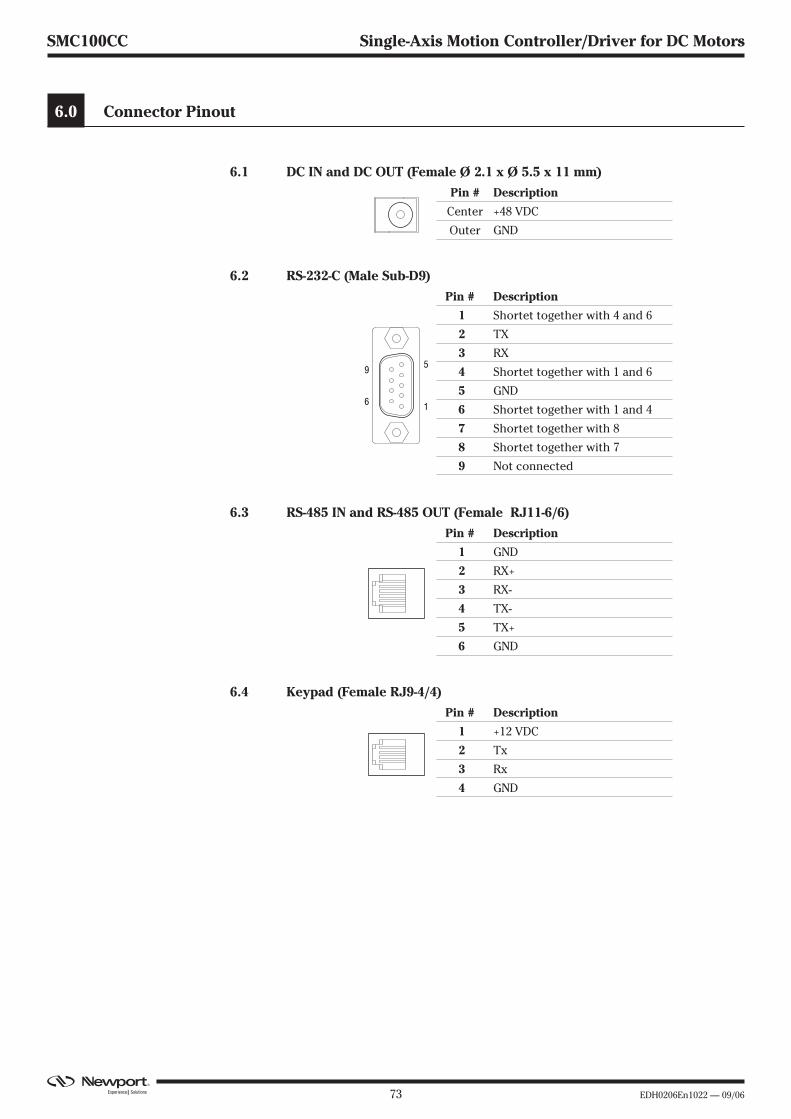
73 EDH0206En1022 — 09/06
SMC100CC Single-Axis Motion Controller/Driver for DC Motors
6.0 Connector Pinout
6.1 DC IN and DC OUT (Female Ø 2.1 x Ø 5.5 x 11 mm)
6.2 RS-232-C (Male Sub-D9)
6.3 RS-485 IN and RS-485 OUT (Female RJ11-6/6)
6.4 Keypad (Female RJ9-4/4)
Pin # Description
1 +12 VDC
2 Tx
3 Rx
4 GND
Pin # Description
1 GND
2 RX+
3 RX-
4 TX-
5 TX+
6 GND
Pin # Description
1 Shortet together with 4 and 6
2 TX
3 RX
4 Shortet together with 1 and 6
5 GND
6 Shortet together with 1 and 4
7 Shortet together with 8
8 Shortet together with 7
9 Not connected
9
6 1
5
Pin # Description
Center +48 VDC
Outer GND
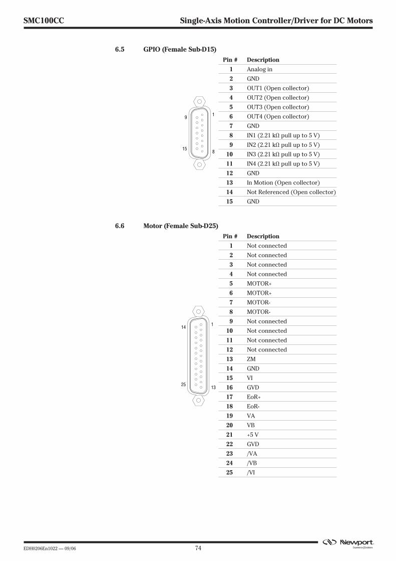
EDH0206En1022 — 09/06 74
SMC100CC Single-Axis Motion Controller/Driver for DC Motors
6.5 GPIO (Female Sub-D15)
6.6 Motor (Female Sub-D25)
Pin # Description
1 Not connected
2 Not connected
3 Not connected
4 Not connected
5 MOTOR+
6 MOTOR+
7 MOTOR-
8 MOTOR-
9 Not connected
10 Not connected
11 Not connected
12 Not connected
13 ZM
14 GND
15 VI
16 GVD
17 EoR+
18 EoR-
19 VA
20 VB
21 +5 V
22 GVD
23 /VA
24 /VB
25 /VI
1325
14 1
Pin # Description
1 Analog in
2 GND
3 OUT1 (Open collector)
4 OUT2 (Open collector)
5 OUT3 (Open collector)
6 OUT4 (Open collector)
7 GND
8 IN1 (2.21 kΩ pull up to 5 V)
9 IN2 (2.21 kΩ pull up to 5 V)
10 IN3 (2.21 kΩ pull up to 5 V)
11 IN4 (2.21 kΩ pull up to 5 V)
12 GND
13 In Motion (Open collector)
14 Not Referenced (Open collector)
15 GND
815
9 1
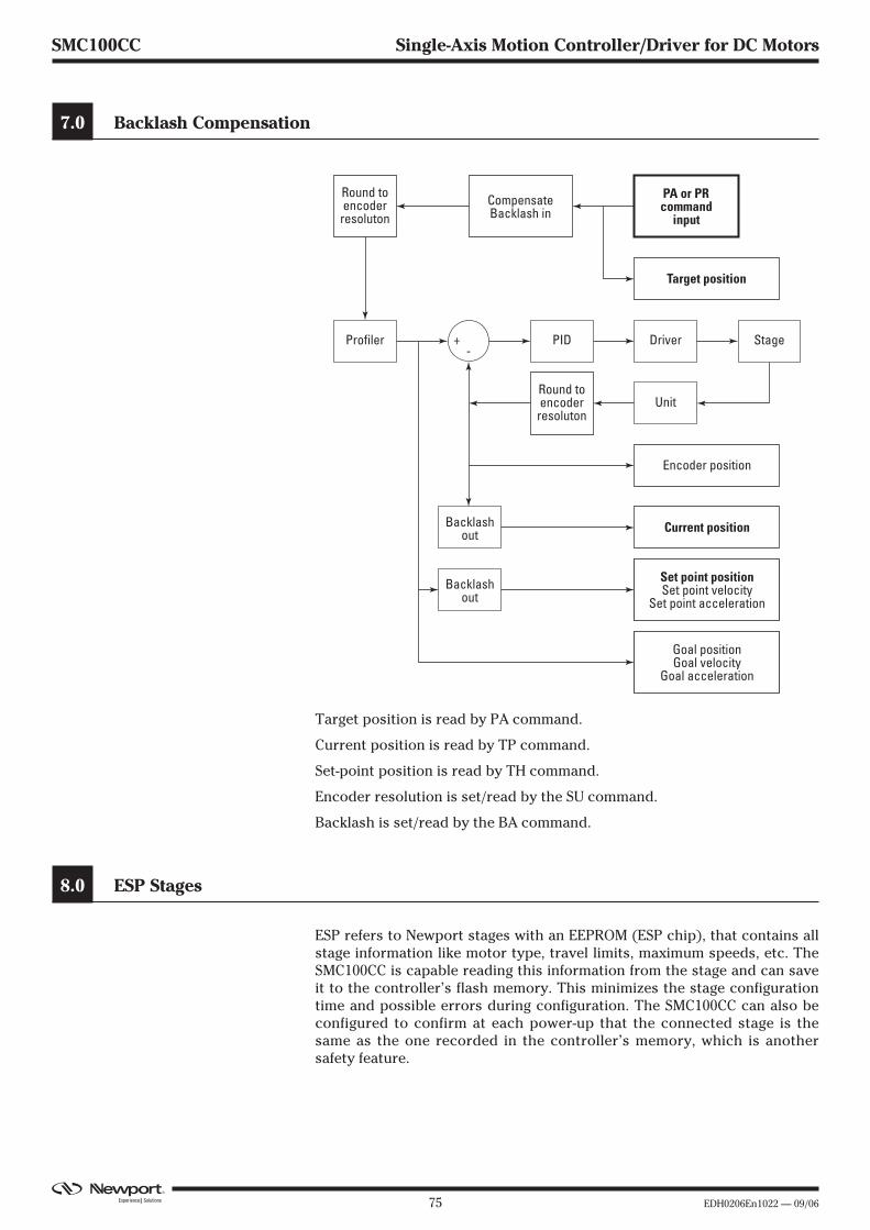
75 EDH0206En1022 — 09/06
SMC100CC Single-Axis Motion Controller/Driver for DC Motors
7.0 Backlash Compensation
Target position is read by PA command.
Current position is read by TP command.
Set-point position is read by TH command.
Encoder resolution is set/read by the SU command.
Backlash is set/read by the BA command.
8.0 ESP Stages
ESP refers to Newport stages with an EEPROM (ESP chip), that contains allstage information like motor type, travel limits, maximum speeds, etc. TheSMC100CC is capable reading this information from the stage and can saveit to the controller’s flash memory. This minimizes the stage configurationtime and possible errors during configuration. The SMC100CC can also beconfigured to confirm at each power-up that the connected stage is thesame as the one recorded in the controller’s memory, which is anothersafety feature.
Round toencoder
resoluton
Profiler Driver+ PID
Backlashout
CompensateBacklash in
Round toencoderresoluton
PA or PRcommand
input
Target position
Unit
Stage-
Encoder position
Current position
Backlashout
Set point positionSet point velocity
Set point acceleration
Goal positionGoal velocity
Goal acceleration
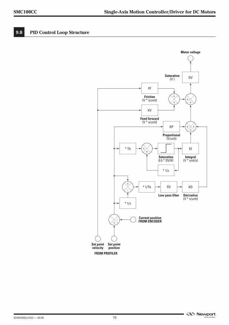
EDH0206En1022 — 09/06 76
SMC100CC Single-Axis Motion Controller/Driver for DC Motors
9.0 PID Control Loop Structure
FF
Friction(V * s/unit)
KV
DV
Feed forward(V * s/unit)
Saturation(V )
KI
* 1/z
Integral(V * unit/s)
Saturation0.5 * DV/KI
* 1/z
* Tb
KP
Proportional(V/unit)
KD
Dérivative(V * s/unit)
FD* 1/Tb
Low pass filter
Current positionFROM ENCODER
FROM PROFILER
Set pointposition
+
+
+
+
+
+
-
Motor voltage
Set pointvelocity
+-
+
+ ++
77 EDH0206En1022 — 09/06
SMC100CC Single-Axis Motion Controller/Driver for DC Motors
10.0 Maintenance and Service
10.1 Enclosure Cleaning
The SMC100CC Controller/Driver should only be cleaned with a lightlydamped cloth or sponge with a soapy water solution. Do not use an ace-tone or alcohol solution, this will damage the finish of the enclosure.
10.2 Obtaining Service
The SMC100CC Controller/Driver contains no user serviceable parts. Toobtain information regarding factory service, contact Newport Corporationor your Newport representative. Please have the following informationavailable:
• Instrument model number (on front panel).
• Instrument serial number (on rear panel) or original order number.
• Description of the problem.
If the instrument is to be returned to Newport Corporation, you will begiven a Return Number, which you should reference in your shipping docu-ments.
Complete a copy of the Service Form as represented on the next page andinclude it with your shipment.
EDH0206En1022 — 09/06 78
SMC100CC Single-Axis Motion Controller/Driver for DC Motors
Service Form Your Local RepresentativeTel.:Fax:
Name:
Company:
Address:
Country:
P.O. Number:
Item(s) Being Returned:
Model #:
Description:
Reasons of return of goods (please list any specific problems):
Return authorization #:(Please obtain prior to return of item)
Date:
Phone Number:
Fax Number:
Serial #:


Visit Newport Online at:
wwwwww..nneewwppoorrtt..ccoomm
North America & Asia
Newport Corporation
1791 Deere Ave.Irvine, CA 92606, USA
Sales
(949) 253-1461 or (800) 222-6440 x31461
e-mail: [email protected]
Technical Support
(949) 253-1406 or (800) 222-6440 x31406
e-mail: [email protected]
Service, RMAs & Returns
(949) 253-1694 or (800) 222-6440 x31694
e-mail: [email protected]
Europe
MICRO-CONTROLE Spectra-Physics S.A
1, rue Jules Guesde – Bât. BZI Bois de l’Épine – BP18991006 Evry CedexFrance
Sales & Technical Support
+33 (0)1.60.91.68.68
e-mail: [email protected]
Service & Returns
+33 (0)2.38.40.51.55