smart-ups™ - apc by schneider electric · 3 1. introduction these instructions describe how to...
TRANSCRIPT

Smart-UPS™Hardwire Kit
InstallationGuide

Entire contents copyright ©1996 American Power Conversion.All rights reserved; reproduction in whole or in part without
permission is prohibited.Smart-UPS is a registered trademark of APC.
All other trademarks are the property of their respective owners.

1
Contents
1. Introduction ................................................ 32. Hardwire Kit Overview................................... 53. Hardwire Kit Contents ................................... 64. Required Materials and Tools ........................... 8
4.1 Required Materials ..............................................84.2 Required Tools ...................................................8
5. Installation .................................................. 95.1 Installing the Hardwire Kit on 100V or 120V Tower
Units .............................................................. 105.2 Installing the Hardwire Kit on 208V Tower Units ...... 195.3 Installing the Hardwire Kit on 100V and 120V Rack
Mount Units .................................................... 295.4 Installing the Hardwire Kit on 208V Rack Mount
Units .............................................................. 37

2
3
1. IntroductionThese instructions describe how to safely install the accessory hardwirekit on the following Smart-UPS models.
SU1400XLT SU2200 SU3000SU1400RMXLT SU2200XL SU3000T
SU2200XLT SU3000RMSU2200RM SU3000JSU2200RMXLT SU3000RMJSU2200XLRMSU2200J
This kit provides the necessary hardware to install direct wiring for in-put connection, output connection or both. Carefully read these in-structions in their entirety before continuing.
WARNING!Only qualified service personnel or electricians mayperform the following procedure. The electrical ter-minals exposed in the following procedures will beenergized if the UPS is on or plugged in. Make surethe UPS is both unplugged and off.
CAUTION!When the input and/or output panels are replaced with this kit, thestandard circuit breakers are eliminated. Properly rated overcurrentprotection must be supplied at the source to protect both the wiring,the UPS, and the loads attached to it. Where an individual load has alower rating for its source overcurrent protection, additional properlyrated overcurrent protection must be supplied for the load(s).

4
The maximum allowed overcurrent protection for each model is givenin the table below. A lower value may be used, but may result in a re-duction of power that can be supplied by the UPS.
ModelNumber
OvercurrentProtection
MaximumInput Current
NominalVoltage
1400XLT1400RMXLT
20A20A
12A12A
208V208V
2200J22002200RM2200XL2200RMXL2200XLT2200RMXLT
30A30A30A30A30A20A20A
24A21A21A24A24A16A16A
100V120V120V120V120V208V208V
3000J3000RMJ30003000RM3000T
40A40A40A40A20A
30A30A28A28A18A
100V100V120V120V208V

5
2. Hardwire Kit OverviewThe Smart-UPS hardwire kit provides the panels and mounting hard-ware for both floor standing (tower) and rack mount Smart-UPSmodels. This kit is used to replace the power distribution outletsand/or input power cord that is originally furnished with the UPS. Theinput and output panels are designed with knockouts for use withstandard sized cable or conduit clamps. Cable or conduit clamps arenot included in this kit.
NOTE: If your Smart-UPS is serial number 9603xxxxxxx or less, youmay be unable to install this hardwire kit to your UPS. Con-tact your dealer for an alternative solution.
6
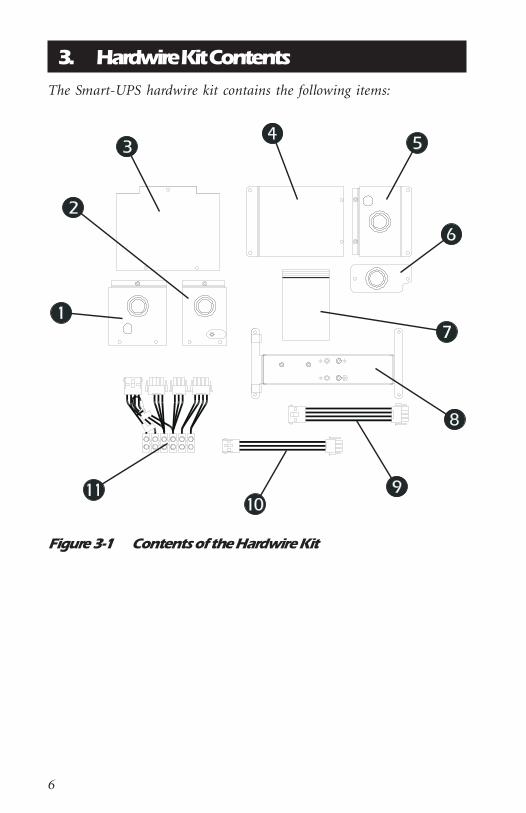
3. Hardwire Kit ContentsThe Smart-UPS hardwire kit contains the following items:
Figure 3-1 Contents of the Hardwire Kit
7
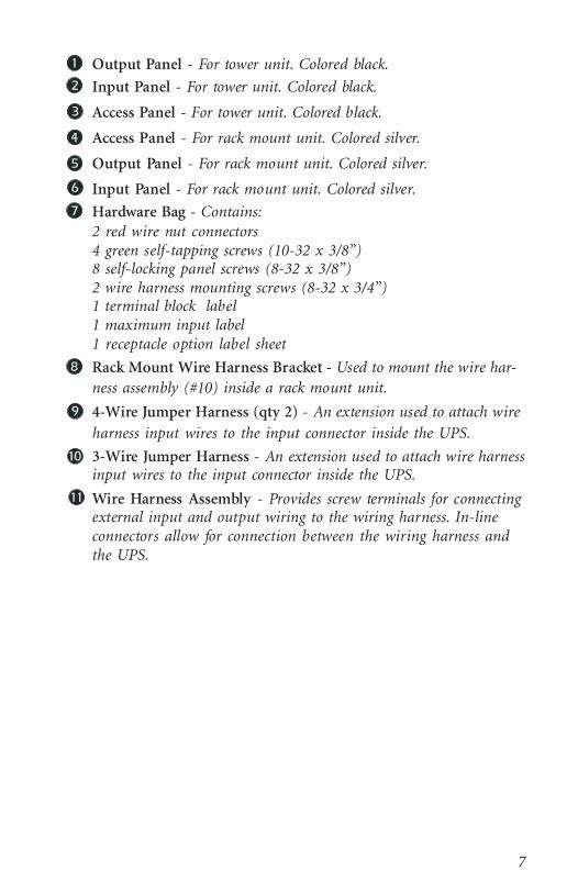
Output Panel - For tower unit. Colored black.
Input Panel - For tower unit. Colored black.
Access Panel - For tower unit. Colored black.
Access Panel - For rack mount unit. Colored silver.
Output Panel - For rack mount unit. Colored silver.
Input Panel - For rack mount unit. Colored silver.
Hardware Bag - Contains:2 red wire nut connectors4 green self-tapping screws (10-32 x 3/8”)8 self-locking panel screws (8-32 x 3/8”)2 wire harness mounting screws (8-32 x 3/4”)1 terminal block label1 maximum input label1 receptacle option label sheet
Rack Mount Wire Harness Bracket - Used to mount the wire har-ness assembly (#10) inside a rack mount unit.
4-Wire Jumper Harness (qty 2) - An extension used to attach wireharness input wires to the input connector inside the UPS.
3-Wire Jumper Harness - An extension used to attach wire harnessinput wires to the input connector inside the UPS.
Wire Harness Assembly - Provides screw terminals for connectingexternal input and output wiring to the wiring harness. In-lineconnectors allow for connection between the wiring harness andthe UPS.
8
4. Required Materials and Tools
4.1 Required MaterialsThe following materials are not included in the hardwire kit and mustbe supplied by the purchaser:• Electrical cable or wiring - Cable or wiring must be of sufficient
current carrying capacity to safely accommodate the attachedloads. Refer to local electrical requirements for the appropriatewire size.
• Electrical conduit or tubing - Conduit or tubing should meet alllocal requirements for electrical wiring.
• Cable or conduit clamps - The hardwire kit requires cable clampsfor the input and output cords. Panel knockouts are sized to accept1/2", 3/4", or 1" clamps.
NOTE: Wiring codes and requirements differ from area to area. Besure to conform to all local electrical requirements when in-stalling and wiring this kit.
4.2 Required ToolsThe following tools are required to install the hardwire kit
● Electrician's Pliers
● Flat Blade Screwdrivers (large and small)
● Phillips Screwdriver
● Wire Cutters

9
5. InstallationThis section provides step by step instructions for installing a hardwirekit to a Smart-UPS tower or rack-mount UPS.
NOTE: The examples used in this manual assume a typical, flexiblecord installation. If you are using tubing, or rigid or flexibleconduit, make the necessary adjustments for the situation. Besure to conform to all local electrical requirements.
Input or Output Only InstallationsInput or Output Only InstallationsInput or Output Only InstallationsInput or Output Only InstallationsInput or Output Only InstallationsIn the event that only the input or only the output is to be hard wired,follow only the portion of the instructions that apply to your installa-tion.
When hard wiring the input only, the existing output panel must be re-moved for access. This panel must then be replaced after the input wir-ing is completed.
Use the following table to locate the correct installation procedure fora specific Smart-UPS model.
Description Model Number Section Page
Smart-UPS Tower(100V or 120V)
SU2200SU2200JSU2200XLSU3000SU3000J
5.1 10
Smart-UPS Tower(208V)
SU1400XLTSU2200XLTSU3000T
5.2 19
Smart-UPS Rack Mount(100V or 120V)
SU2200RMSU2200XLRMSU3000RMSU3000RMJ
5.3 29
Smart-UPS Rack Mount(208V)
SU1400RMXLTSU2200RMXLT
5.4 37

10
5.1 Installing the Hardwire Kit on 100V or 120VTower Units
Follow the procedures in this section to install the hardwire kit to a100V or 120V Smart-UPS in the tower configuration (Model numbersSU2200, SU2200J, SU2200XL, and SU3000, SU3000J).
5.1.1 Removing the Rear Panels
Remove the Output Panel
1. Unpack and inspect the hardwire kit. Notify the carrier and dealerimmediately if there is damage. Recycle the packaging or disposeof it properly.
2. Prepare the UPS for installation. Shut down any protected loads(computers, etc.), if present. Unplug all loads from the output re-ceptacles of the UPS.
3. IMPORTANT: Turn off the UPS and unplug it from the wall out-let.
4. Unscrew the output panel at the rear of the UPS. Remove only the4 screws indicated in Figure 5-1. Save these screws. They will beused to install the replacement panels.
Figure 5-1 Removal of Output Panel (100V and 120V Tower)
11
5. Pull the panel out gently so that the 3-pin and 4-pin in-lineconnectors are accessible.
6. Squeeze the locking tabs on the sides of the connectors and pullthe connectors apart. Do not pull on the wires.
7. If the serial number decal is located on the output panel, remove itand replace it onto the permanent, upper panel on the back of theUPS.
8. Discard the output panel.
Remove the Input Panel
NOTE: If you are hard wiring only the output, skip this section andcontinue with Section 5.1.2.
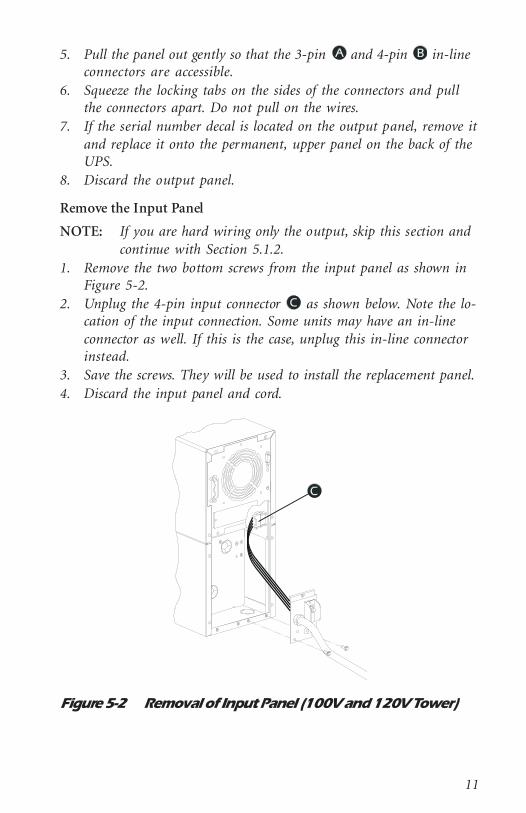
1. Remove the two bottom screws from the input panel as shown inFigure 5-2.
2. Unplug the 4-pin input connector as shown below. Note the lo-cation of the input connection. Some units may have an in-lineconnector as well. If this is the case, unplug this in-line connectorinstead.
3. Save the screws. They will be used to install the replacement panel.4. Discard the input panel and cord.
Figure 5-2 Removal of Input Panel (100V and 120V Tower)

12
5.1.2 Verifying the Presence of Mounting Holes
1. Examine the rear plate inside the UPS. The configuration of themounting holes should appear as in Figure 5-3. If the mountingand ground screw holes are present in this configuration, proceedwith the installation procedure. If the holes are not present, youwill not be able to install the hardwire kit to this UPS. Contactyour dealer for an alternative solution.
Figure 5-3 Wire Harness Mounting Holes
5.1.3 Installing the Wire Harness Assembly
NOTE: If you are hard wiring the input only, choose one of the fol-lowing two methods:
A. Mount the wire harness as instructed (Section 5.1.3), andwire only the Input L1 and Input L2/N connectionsor,
B. Retrieve the old line cord and cut the last 6” from the endwith the 4-wire connector attached. This connector and theattached wires will be spliced to your input line. Using ap-proved field-applied splicing devices, connect the two blackwires to Line1 (or Hot) of your input line and the two whitewires to Line2 (or Neutral) of your input line. Plug the con-nector into the mating connector in the UPS (Figure 5-2)and reinstall the input and output panels.
13
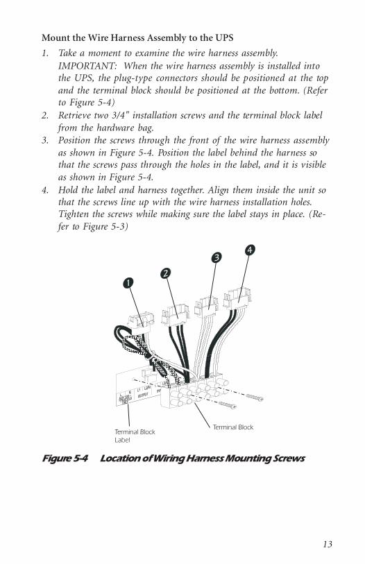
Mount the Wire Harness Assembly to the UPS
1. Take a moment to examine the wire harness assembly.IMPORTANT: When the wire harness assembly is installed intothe UPS, the plug-type connectors should be positioned at the topand the terminal block should be positioned at the bottom. (Referto Figure 5-4)
2. Retrieve two 3/4" installation screws and the terminal block labelfrom the hardware bag.
3. Position the screws through the front of the wire harness assemblyas shown in Figure 5-4. Position the label behind the harness sothat the screws pass through the holes in the label, and it is visibleas shown in Figure 5-4.
4. Hold the label and harness together. Align them inside the unit sothat the screws line up with the wire harness installation holes.Tighten the screws while making sure the label stays in place. (Re-fer to Figure 5-3)
Figure 5-4 Location of Wiring Harness Mounting Screws

14
Connect the Wire Harness Assembly to the UPS
Electrical connection between the wire harness assembly and the UPSis accomplished through the use of the four in-line connectors on thewire harness assembly and the corresponding connectors inside theUPS. Carefully follow the procedure below to ensure that the connec-tions are made properly.
NOTE: Engage the connectors by holding one connector firmly ineach hand, and fitting them together. Be sure to seat the connec-tors fully in place - they lock together with a click.
1. Refer to Figure 5-4 for connector numbers.2. Retrieve the four-wire, yellow jumper harness (Figure 3-1, item
#9).3. Plug connector #4 into the “female” end of the jumper harness.4. Connect the “male” end of the jumper harness into the 4-pin plug
located inside the UPS. (Connector in Figure 5-2)5. Plug connector #3 to the 3-pin output connector inside the UPS.
(Connector in Figure 5-1)6. Plug connector #2 to the 4-pin output connector inside the UPS.
(Connector in Figure 5-1)7. Connector #1 is not used in this application. Leave this plug un-
connected.8. Double check all connections. Make sure that all connections are
firmly locked together. Pay close attention that connectors #2 and#4 are connected correctly.
5.1.4 Connecting External Wiring to the UPS
The wire harness assembly provides a terminal block equipped withscrew terminals to attach input and output wiring. Follow the proce-dure below to connect input and output wiring to the wire harness as-sembly.
Connect Input Wiring to the Wire Harness Assembly
CAUTION: Make sure input wiring is not live!!1. Locate the input panel from the hardwire kit (Figure 3-1, item #2)
and remove the appropriate size knockout from the panel. Install acable clamp so that it can be tightened from the outside of the unitonce the panel is installed.
15
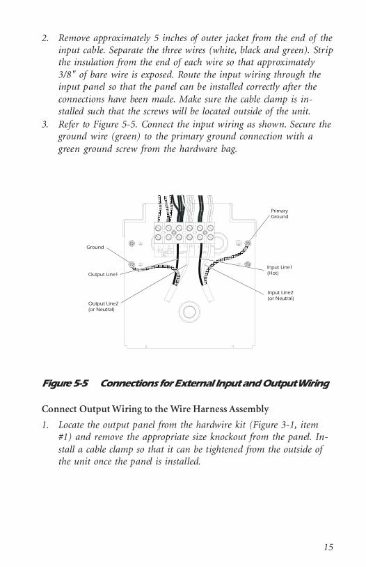
2. Remove approximately 5 inches of outer jacket from the end of theinput cable. Separate the three wires (white, black and green). Stripthe insulation from the end of each wire so that approximately3/8" of bare wire is exposed. Route the input wiring through theinput panel so that the panel can be installed correctly after theconnections have been made. Make sure the cable clamp is in-stalled such that the screws will be located outside of the unit.
3. Refer to Figure 5-5. Connect the input wiring as shown. Secure theground wire (green) to the primary ground connection with agreen ground screw from the hardware bag.
Figure 5-5 Connections for External Input and Output Wiring
Connect Output Wiring to the Wire Harness Assembly
1. Locate the output panel from the hardwire kit (Figure 3-1, item#1) and remove the appropriate size knockout from the panel. In-stall a cable clamp so that it can be tightened from the outside ofthe unit once the panel is installed.

16
2. Remove approximately 5 inches of outer jacket from the end of theoutput cable. Separate the three wires (white, black and green).Strip the insulation from the end of each wire so that approxi-mately 3/8" of bare wire is exposed. Route the output wiringthrough the output panel so that the panel can be installed cor-rectly after the connections have been made. Make sure the cableclamp is installed such that the screws will be located outside ofthe unit.
3. Refer to Figure 5-5. Connect the output wiring as shown. Securethe ground wire (green) to one of the ground holes with a greenground screw from the hardware bag.
5.1.5 Installation of New Rear Panels
Before closing up the back of the unit, make sure that all wiring hasbeen properly installed:1. Output wiring is connected to the center two screw terminals on
the terminal block.2. Input wiring is connected to the last two screw terminals on the
terminal block.
Make sure all ground wires (green) are securely fastened to an appro-priate ground screw.
Install the Output Panel
1. Slide the output panel into position as shown in Figure 5-6. Fastenthe panel to the UPS with two self-locking panel screws.
2. Make sure there are a few inches of slack output cable tucked in-side the unit.
3. Tighten the cable clamp. The clamp will prevent strain on the con-nections if the output cable is accidentally pulled.
Install the Input Panel
1. Slide the input panel into position as shown in Figure 5-6. Fastenthe panel to the UPS with two self-locking panel screws.
2. Make sure there are a few inches of slack output cable tucked in-side the unit.
3. Tighten the cable clamp. The clamp will prevent strain on the con-nections if the input cable is accidentally pulled.

17
Figure 5-6 Installation of Input and Output Panels (100V and120V Tower)
Install the Access Panel
1. Slide the access panel (Figure 3-1, item #3) into position as shownin Figure 5-7. Make sure printed side is facing out.
2. Fasten the panel to the UPS with three self-locking panel screws asshown.
Figure 5-7 Installation of Access Panel (100V and 120VTower)

18
5.1.6 Final Installation Procedure
Two labels must be applied to the chassis of the Smart-UPS unit tocomplete the installation.1. Retrieve the Receptacle Option label sheet and the Input label
from the hardware bag.2. Remove the small “R31” label from the Option label sheet and ap-
ply it to the rear of the chassis, directly below the existing model/serial number label.Note: Be careful not to cover any portion of the existing model/
serial number label.3. Remove the Input label from its backing and apply it to the side
panel of the Smart-UPS unit. (Figure 5-8)4. IMPORTANT: Make sure that all external wiring has been com-
pleted before turning on the UPS.
Figure 5-8 Input Label Location (100V and 120V Tower)
19
5.2 Installing the Hardwire Kit on 208V Tower UnitsFollow the procedures in this section to install the hardwire kit to a208V Smart-UPS in the tower configuration (Model numbersSU1400XLT, SU2200XLT, and SU3000T).
5.2.1 Removing the Rear Panels
Remove the Output Panel
1. Unpack and inspect the hardwire kit. Notify the carrier and dealerimmediately if there is damage. Recycle the packaging or disposeof it properly.
2. Prepare the UPS for installation. Shut down any protected loads(computers, etc.), if present. Unplug all loads from the output re-ceptacles of the UPS.
3. IMPORTANT: Turn off the UPS and unplug it from the wall out-let.
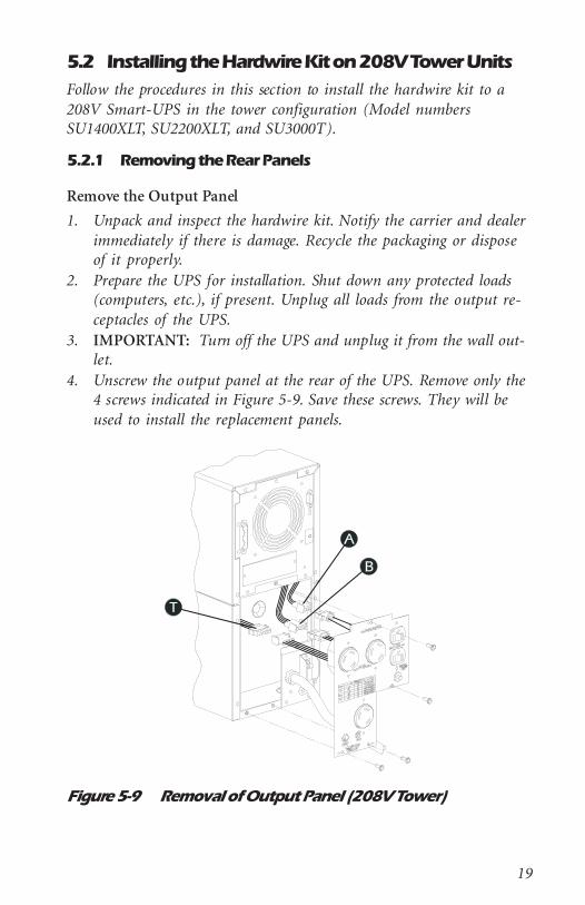
4. Unscrew the output panel at the rear of the UPS. Remove only the4 screws indicated in Figure 5-9. Save these screws. They will beused to install the replacement panels.
Figure 5-9 Removal of Output Panel (208V Tower)

20
5. Pull the panel out gently so that the 3-pin , 4-pin , and 4-pin in-line connectors are accessible.
6. Squeeze the locking tabs on the sides of the connectors and pullthe connectors apart. Do not pull on the wires.
7. Disconnect the two wires from the rear of the circuit breaker onthe output panel. Working from the front side of the output panel,use a small screwdriver to apply pressure to the side of the circuitbreaker and push it free of the panel. Save the circuit breaker forreinstallation into the new output panel.
8. If the serial number decal is located on the output panel, remove itand replace it on the permanent, upper panel on the back of theUPS.
9. Discard the output panel.
Remove the Input Panel
NOTE: If you are hard wiring only the output, skip this section andcontinue with Section 5.2.2.
1. Remove the two bottom screws from the input panel as shown inFigure 5-10.
2. Unplug the 4-pin input connector as shown below. Note the lo-cation of the input connection.
3. Save the screws. They will be used to install the replacement panel.4. Discard the input panel and cord.
Figure 5-10 Removal of Input Panel (208V Tower)

21
5.2.2 Verifying the Presence of Mounting Holes
1. Examine the rear plate inside the UPS. The configuration of themounting holes should appear as in Figure 5-11. If the mountingand ground screw holes are present in this configuration, proceedwith the installation procedure. If the holes are not present, youwill not be able to install the hardwire kit to this UPS. Contactyour dealer for an alternative solution.
Figure 5-11 Wire Harness Mounting Holes
5.2.3 Installing the Wire Harness Assembly
NOTE: If you are hard wiring the input only, choose one of the fol-lowing two methods:
A. Mount the wire harness as instructed (Section 5.2.3), andwire only the Input L1 and Input L2/N connectionsor,
B. Retrieve the old line cord and cut the last 6” from the endwith the 4-wire connector attached. This connector and theattached wires will be spliced to your input line. Using ap-proved field-applied splicing devices, connect the two blackwires to Line1 (or Hot) of your input line and the two whitewires to Line2 (or Neutral) of your input line. Plug the con-nector into the mating connector in the UPS (Figure 5-10)and reinstall the input and output panels.
22
Mount the Wire Harness Assembly to the UPS
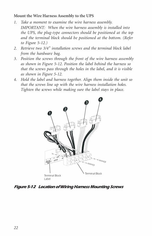
1. Take a moment to examine the wire harness assembly.IMPORTANT: When the wire harness assembly is installed intothe UPS, the plug-type connectors should be positioned at the topand the terminal block should be positioned at the bottom. (Referto Figure 5-12.)
2. Retrieve two 3/4" installation screws and the terminal block labelfrom the hardware bag.
3. Position the screws through the front of the wire harness assemblyas shown in Figure 5-12. Position the label behind the harness sothat the screws pass through the holes in the label, and it is visibleas shown in Figure 5-12.
4. Hold the label and harness together. Align them inside the unit sothat the screws line up with the wire harness installation holes.Tighten the screws while making sure the label stays in place.
Figure 5-12 Location of Wiring Harness Mounting Screws

23
Connect the Wire Harness Assembly to the UPS
Electrical connection between the wire harness assembly and the UPSis accomplished through the use of the four in-line connectors on thewire harness assembly and the corresponding connectors inside theUPS. Carefully follow the procedure below to ensure that the connec-tions are made properly.
NOTE: Engage the connectors by holding one connector firmly ineach hand, and fitting them together. Be sure to seat the connec-tors fully in place - they lock together with a click.
1. Refer to Figure 5-12 for connector numbers.2. Retrieve the four-wire, yellow jumper harness (Figure 3-1, item
#9).3. Plug connector #4 into the “female” end of the jumper harness.4. Connect the “male” end of the jumper harness into the 4-pin plug
located inside the UPS. (Connector in Figure 5-10)5. Plug connector #3 to the 3-pin output connector inside the UPS.
(Connector in Figure 5-9)6. Plug connector #2 to the 4-pin output connector inside the UPS.
(Connector in Figure 5-9)7. Cut the wire tie securing the wires to connector #1 and separate
the wires.a. Plug connector #1 into the 4-pin transformer connector inside
the UPS. (Connector in Figure 5-9)b. Connect the two “push-on” terminals to the circuit breaker
that was removed from the original output panel. (Section5.2.1)
c. Use a green screw from the hardware bag to secure the greenground wire to one of the ground screws holes on the panelinside the rear of the UPS. (Refer to Figure 5-13)
8. Double check all connections. Make sure all connections are firmlylocked together. Pay close attention that connectors #2 and #4 areconnected correctly.
5.2.4 Connecting External Wiring to the UPS
The wire harness assembly provides a terminal block equipped withscrew terminals to attach input and output wiring. Follow the proce-dure below to connect input and output wiring to the wire harness as-sembly.

24
Connect Input Wiring to the Wire Harness Assembly
CAUTION: Make sure input wiring is not live!!1. Locate the input panel from the hardwire kit (Figure 3-1, item #2)
and remove the appropriate size knockout from the panel. Install acable clamp so that it can be tightened from the outside of the unitonce the panel is installed.
2. Remove approximately 5 inches of outer jacket from the end of theinput cable. Separate the three wires (white, black and green). Stripthe insulation from the end of each wire so that approximately3/8" of bare wire is exposed. Route the input wiring through theinput panel so that the panel can be installed correctly after theconnections have been made. Make sure that the cable clamp is in-stalled such that the screws will be located outside of the unit.
3. Refer to Figure 5-13. Connect the input wiring as shown. Securethe ground wire (green) to the primary ground connection with agreen ground screw from the hardware bag.
Figure 5-13 Connections for External Input and Output Wiring(208V Tower)
25
Connect Output Wiring to the Wire Harness Assembly
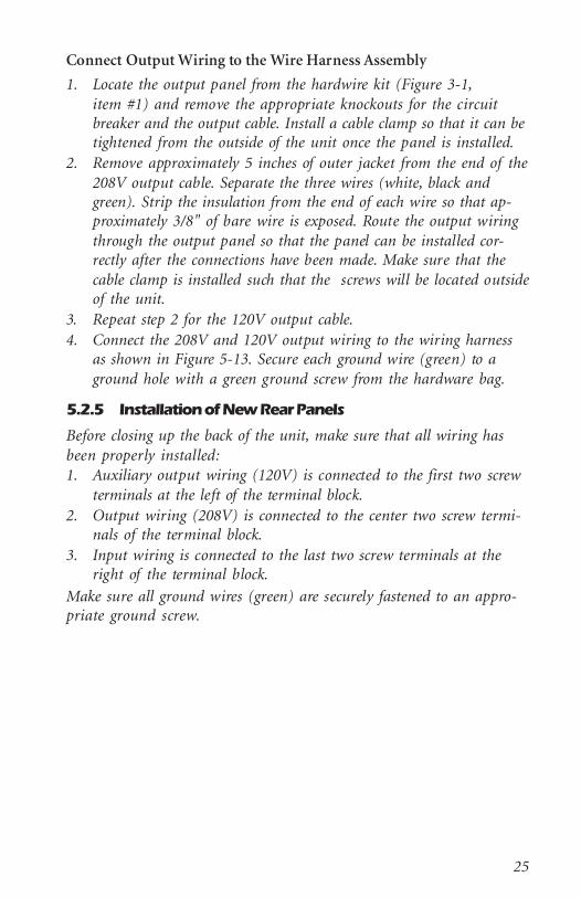
1. Locate the output panel from the hardwire kit (Figure 3-1,item #1) and remove the appropriate knockouts for the circuitbreaker and the output cable. Install a cable clamp so that it can betightened from the outside of the unit once the panel is installed.
2. Remove approximately 5 inches of outer jacket from the end of the208V output cable. Separate the three wires (white, black andgreen). Strip the insulation from the end of each wire so that ap-proximately 3/8" of bare wire is exposed. Route the output wiringthrough the output panel so that the panel can be installed cor-rectly after the connections have been made. Make sure that thecable clamp is installed such that the screws will be located outsideof the unit.
3. Repeat step 2 for the 120V output cable.4. Connect the 208V and 120V output wiring to the wiring harness
as shown in Figure 5-13. Secure each ground wire (green) to aground hole with a green ground screw from the hardware bag.
5.2.5 Installation of New Rear Panels
Before closing up the back of the unit, make sure that all wiring hasbeen properly installed:1. Auxiliary output wiring (120V) is connected to the first two screw
terminals at the left of the terminal block.2. Output wiring (208V) is connected to the center two screw termi-
nals of the terminal block.3. Input wiring is connected to the last two screw terminals at the
right of the terminal block.
Make sure all ground wires (green) are securely fastened to an appro-priate ground screw.

26
Install the Output Panel
1. Slide the output panel into position as shown in Figure 5-14. In-stall the circuit breaker by pushing it through the hole in the out-put panel until it snaps into place. Fasten the panel to the UPSwith two self-locking panel screws.
2. Make sure there are a few inches of slack output cable tucked in-side the unit.
3. Tighten the cable clamp. The clamp will prevent strain on the con-nections if the output cable is accidentally pulled.
Figure 5-14 Installation of Input and Output Panels (208VTower)
Install the Input Panel
1. Slide the input panel into position as shown in Figure 5-14. Fastenthe panel to the UPS with two self-locking panel screws.
2. Make sure there are a few inches of slack input cable tucked insidethe unit.
3. Tighten the cable clamp. The clamp will prevent strain on the con-nections if the input cable is accidentally pulled.

27
Install the Access Panel
1. Slide the access panel (Figure 3-1, item #3) into position as shownin Figure 5-15. Make sure printed side is facing out.
2. Fasten the panel to the UPS with three self-locking panel screws asshown.
Figure 5-15 Installation of Access Panel (208V Tower)
28
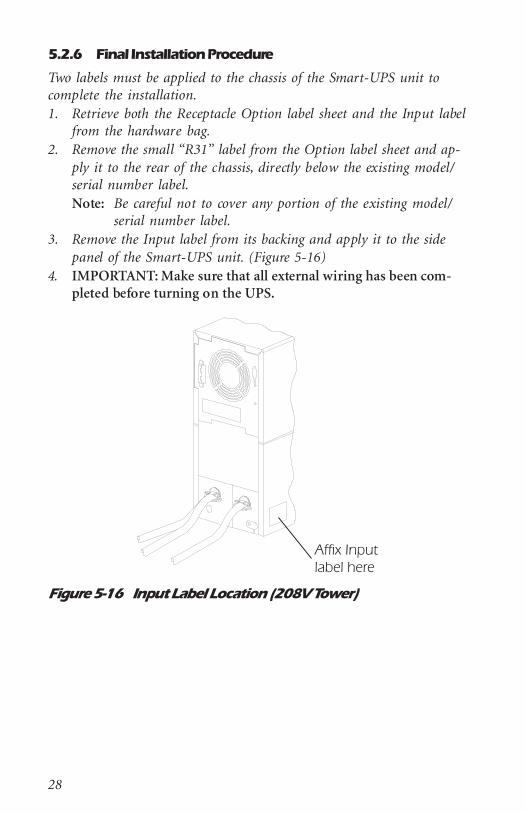
5.2.6 Final Installation Procedure
Two labels must be applied to the chassis of the Smart-UPS unit tocomplete the installation.1. Retrieve both the Receptacle Option label sheet and the Input label
from the hardware bag.2. Remove the small “R31” label from the Option label sheet and ap-
ply it to the rear of the chassis, directly below the existing model/serial number label.Note: Be careful not to cover any portion of the existing model/
serial number label.3. Remove the Input label from its backing and apply it to the side
panel of the Smart-UPS unit. (Figure 5-16)4. IMPORTANT: Make sure that all external wiring has been com-
pleted before turning on the UPS.
Figure 5-16 Input Label Location (208V Tower)

29
5.3 Installing the Hardwire Kit on 100V and 120VRack Mount Units
Follow the procedures in this section to install the hardwire kit to a 100V or 120V Smart-UPS in the rack mount configuration (Model num-bers SU2200RM, SU2200XLRM, SU3000RM, and SU3000RMJ).
5.3.1 Removing the Rear Panels
Remove the Output Panel
1. Unpack and inspect the hardwire kit. Notify the carrier and dealerimmediately if there is damage. Recycle the packaging or disposeof it properly.
2. Prepare the UPS for installation. Shut down any protected loads(computers, etc.), if present. Unplug all loads from the output re-ceptacles of the UPS.
3. IMPORTANT: Turn off the UPS and unplug it from the wall out-let.
4. Unscrew the output panel at the rear of the UPS. Remove only the4 screws indicated in Figure 5-17.
Figure 5-17 Removal of Output Panel (100V and 120V RackMount)
5. Pull the panel out gently so that the 3-pin and 4-pin connec-tors are accessible.
6. Squeeze the locking tabs on the sides of the connectors and unplugthe connectors from the printed circuit board. Note the location ofthe connectors.
7. Discard the output panel.

30
Remove the Input Panel
NOTE: If you are hard wiring only the output, skip this section andcontinue with Section 5.3.2.
1. Remove the two screws from the input panel as shown in Figure 5-18.
2. Unplug the 4 pin input connector as shown below. Note the lo-cation of the input connection.
3. Discard the input panel and cord.
Figure 5-18 Removal of Input Panel (100V and 120V RackMount)
5.3.2 Installing the Wire Harness Assembly
NOTE: If you are hard wiring the input only, retrieve the old linecord and cut the last 6” from the end with the 4-wire con-nector attached. This connector and the attached wires willbe spliced to your input line. Using approved field-appliedsplicing devices, connect the two black wires to Line1 (orHot) of your input line and the two white wires to Line2 (orNeutral) of your input line. Plug the connector into the mat-ing connector in the UPS (Figure 5-18) and reinstall the in-put and output panels.
Mount the Wire Harness Assembly to the UPS
1. Take a moment to examine the wire harness assembly.IMPORTANT: When the wire harness assembly is installed intothe UPS, the plug-type connectors should be positioned at the topand the terminal block should be positioned at the bottom. (Referto Figure 5-19.)
31
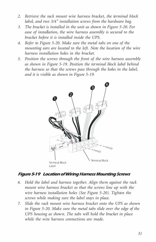
2. Retrieve the rack mount wire harness bracket, the terminal blocklabel, and two 3/4" installation screws from the hardware bag.
3. The bracket is installed in the unit as shown in Figure 5-20. Forease of installation, the wire harness assembly is secured to thebracket before it is installed inside the UPS.
4. Refer to Figure 5-20. Make sure the metal tabs on one of themounting ears are located to the left. Note the location of the wireharness installation holes in the bracket.
5. Position the screws through the front of the wire harness assemblyas shown in Figure 5-19. Position the terminal block label behindthe harness so that the screws pass through the holes in the label,and it is visible as shown in Figure 5-19.
Figure 5-19 Location of Wiring Harness Mounting Screws
6. Hold the label and harness together. Align them against the rackmount wire harness bracket so that the screws line up with thewire harness installation holes (See Figure 5-20). Tighten thescrews while making sure the label stays in place.
7. Slide the rack mount wire harness bracket onto the UPS as shownin Figure 5-20. Make sure the metal tabs slide over the edge of theUPS housing as shown. The tabs will hold the bracket in placewhile the wire harness connections are made.

32
Figure 5-20 Installing the Wire Harness Mounting Bracket(100V and 120V Rack Mount)
Connect the Wire Harness Assembly to the UPS
Electrical connection between the wire harness assembly and the UPSis accomplished through the use of the four in-line connectors on thewire harness assembly and the corresponding connectors inside theUPS. Carefully follow the procedure below to ensure that the connec-tions are made properly.
NOTE: Engage the connectors by holding one connector firmly ineach hand, and fitting them together. Be sure to seat the connec-tors fully in place - they lock together with a click.
1. Refer to Figure 5-19 for connector numbers.2. Retrieve one of the four-wire, yellow jumper harnesses (Figure 3-1,
item #9). Plug the “female” end of the jumper harness into connec-tor #4. Connect the “male” end of the jumper harness to the 4-pinplug located inside the UPS. (Connector in Figure 5-18)
3. Retrieve the other four-wire, yellow jumper harness. Plug the “fe-male” end of the jumper harness into connector #2. Connect the“male” end of the jumper harness to the 4-pin plug located insidethe UPS. (Connector in Figure 5-17)
4. Retrieve the 3-wire jumper harness (Figure 3-1, item #10). Plugthe “female” end of the jumper harness into connector #3. Connectthe “male” end of the jumper harness to the 3-pin output connec-tor inside the UPS. (Connector in Figure 5-17)
5. Connector #1 is not used in this application. Leave this plug un-connected.

33
6. Double check all connections. Make sure all connections are firmlylocked together. Pay close attention that connectors #2 and #4 areconnected correctly.
5.3.3 Connecting External Wiring to the UPS
The wire harness assembly provides a terminal block equipped withscrew terminals to attach input and output wiring. Follow the proce-dure below to connect input and output wiring to the wire harness as-sembly.
Connect Input Wiring to the Wire Harness Assembly
CAUTION: Make sure input wiring is not live!!1. Locate the input panel from the hardwire kit (Figure 3-1, item #6)
and remove the appropriate size knockout from the panel. Install acable clamp so that it can be tightened from the outside of the unitonce the panel is installed.
2. Remove approximately 5 inches of outer jacket from the end of theinput cable. Separate the three wires (white, black and green). Stripthe insulation from the end of each wire so that approximately3/8" of bare wire is exposed. Route the input wiring through theinput panel so that the panel can be installed correctly after theconnections have been made. Make sure that the cable clamp is in-stalled such that the screws will be located outside of the unit.
3. Refer to Figure 5-21. Connect the input wiring as shown. Securethe ground wire (green) to the primary ground connection with agreen ground screw from the hardware bag.
Connect Output Wiring to the Wire Harness Assembly
1. Locate the output panel from the hardwire kit (Figure 3-1,item #5) and remove the appropriate size knockout from thepanel. Install a cable clamp so that it can be tightened from theoutside of the unit once the panel is installed.
2. Remove approximately 5 inches of outer jacket from the end of theoutput cable. Separate the three wires (white, black and green).Strip the insulation from the end of each wire so that approxi-mately 3/8" of bare wire is exposed. Route the output wiringthrough the output panel so that the panel can be installed cor-rectly after the connections have been made. Make sure that thecable clamp is installed such that the screws will be located outsideof the unit.

34
3. Refer to Figure 5-21. Connect the output wiring as shown. Securethe ground wire (green) to one of the ground holes with a greenground screw from the hardware bag.
Figure 5-21 Connections for External Input and Output Wiring(100V and 120V Rack Mount)
5.3.4 Installation of New Rear Panels
Before closing up the back of the unit, make sure that all wiring hasbeen properly installed:1. Input wiring should be connected to the last two screw terminals
at the right of the terminal block.2. Output wiring should be connected to the center two screw termi-
nals of the terminal block.
Make sure all ground wires (green) are securely fastened to a groundscrew.
Install the Output Panel
1. Slide the output panel into position as shown in Figure 5-22. Fas-ten the panel to the UPS with 2 screws from the hardware bag.
2. Make sure there are a few inches of slack output cable tucked in-side the unit.
3. Tighten the cable clamp. The clamp will prevent strain on the con-nections if the output cable is accidentally pulled.

35
Install the Input Panel
1. Slide the input panel into position as shown in Figure 5-22. Fastenthe panel into position as shown. Fasten the panel to the UPS withtwo self-locking panel screws from the hardware bag.
2. Make sure there are a few inches of slack input cable tucked insidethe unit.
3. Tighten the cable clamp. The clamp will prevent strain on the con-nections if the input cable is accidentally pulled.
Figure 5-22 Installation of Input and Output Panels (100V and120V Rack Mount)
Install the Access Panel
1. Slide the access panel (Figure 3-1, item #4) into position as shownin Figure 5-23. Make sure that the printed side faces out.
2. Fasten the panel to the UPS with 4 self-locking panel screws fromthe hardware bag.
36
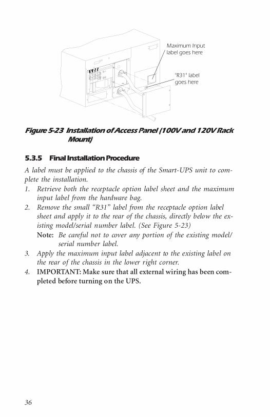
Figure 5-23 Installation of Access Panel (100V and 120V RackMount)
5.3.5 Final Installation Procedure
A label must be applied to the chassis of the Smart-UPS unit to com-plete the installation.1. Retrieve both the receptacle option label sheet and the maximum
input label from the hardware bag.2. Remove the small “R31” label from the receptacle option label
sheet and apply it to the rear of the chassis, directly below the ex-isting model/serial number label. (See Figure 5-23)Note: Be careful not to cover any portion of the existing model/
serial number label.3. Apply the maximum input label adjacent to the existing label on
the rear of the chassis in the lower right corner.4. IMPORTANT: Make sure that all external wiring has been com-
pleted before turning on the UPS.

37
5.4 Installing the Hardwire Kit on 208V Rack MountUnits
Follow the procedures in this section to install the hardwire kit to a208V Smart-UPS in the rack mount configuration (Model numbersSU1400RMXLT and SU2200RMXLT).
5.4.1 Removing the Rear Panels
Remove the Output Panel
1. Unpack and inspect the hardwire kit. Notify the carrier and dealerimmediately if there is damage. Recycle the packaging or disposeof it properly.
2. Prepare the UPS for installation. Shut down any protected loads(computers, etc.), if present. Unplug all loads from the output re-ceptacles of the UPS.
3. IMPORTANT: Turn off the UPS and unplug it from the wall out-let.
4. Unscrew the output panel at the rear of the UPS. Remove only the4 screws indicated in Figure 5-24.
Figure 5-24 Removal of Output Panel (208V Rack Mount)
5. Pull the panel out gently so that the 3-pin , 4-pin , and 4-pin in-line connectors are accessible.
6. Squeeze the locking tabs on the sides of the connectors and unplugthe connectors from the printed circuit board. Note the location ofthe connectors.

38
7. Disconnect the two wires from the rear of the circuit breaker onthe output panel. Working from the front side of the output panel,use a small screwdriver to apply pressure to the side of the circuitbreaker and push it free of the panel. Save the circuit breaker forreinstallation into the new output panel.
8. Discard the output panel and the 4 screws.
Remove the Input Panel
NOTE: If you are hard wiring only the output, skip this section andcontinue with Section 5.4.2.
1. Remove the two screws from the input panel as shown in Figure 5-25.
2. Unplug the 4-pin input connector as shown below. Note the lo-cation of the input connection.
3. Discard the input panel, cord, and screws.
Figure 5-25 Removal of Output Panel (208V Rack Mount)
5.4.2 Installing the Wire Harness Assembly
NOTE: If you are hard wiring the input only, retrieve the old linecord and cut the last 6” from the end with the 4-wire con-nector attached. This connector and the attached wires willbe spliced to your input line. Using approved field-appliedsplicing devices, connect the two black wires to Line1 (orHot) of your input line and the two white wires to Line2 (orNeutral) of your input line. Plug the connector into the mat-ing connector in the UPS (Figure 5-25) and reinstall the in-put and output panels.
39
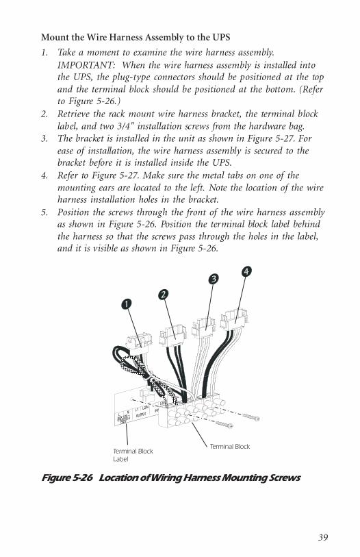
Mount the Wire Harness Assembly to the UPS
1. Take a moment to examine the wire harness assembly.IMPORTANT: When the wire harness assembly is installed intothe UPS, the plug-type connectors should be positioned at the topand the terminal block should be positioned at the bottom. (Referto Figure 5-26.)
2. Retrieve the rack mount wire harness bracket, the terminal blocklabel, and two 3/4" installation screws from the hardware bag.
3. The bracket is installed in the unit as shown in Figure 5-27. Forease of installation, the wire harness assembly is secured to thebracket before it is installed inside the UPS.
4. Refer to Figure 5-27. Make sure the metal tabs on one of themounting ears are located to the left. Note the location of the wireharness installation holes in the bracket.
5. Position the screws through the front of the wire harness assemblyas shown in Figure 5-26. Position the terminal block label behindthe harness so that the screws pass through the holes in the label,and it is visible as shown in Figure 5-26.
Figure 5-26 Location of Wiring Harness Mounting Screws

40
6. Hold the label and harness together. Align them against the rackmount wire harness bracket so that the screws line up with thewire harness installation holes. (See Figure 5-27) Tighten thescrews while making sure the label stays in place.
7. Slide the rack mount wire harness bracket onto the UPS as shownin Figure 5-27. Make sure the metal tabs slide over the edge of theUPS housing as shown. The tabs will hold the bracket in placewhile the wire harness connections are made.
Figure 5-27 Installing the Wire Harness Mounting Bracket(208V Rack Mount)
Connect the Wire Harness Assembly to the UPS
Electrical connection between the wire harness assembly and the UPSis accomplished through the use of the four in-line connectors on thewire harness assembly and the corresponding connectors inside theUPS. Carefully follow the procedure below to ensure that the connec-tions are made properly.
NOTE: Engage the connectors by holding one connector firmly ineach hand, and fitting them together. Be sure to seat the connec-tors fully in place - they lock together with a click.
1. Refer to Figure 5-26 for connector numbers.2. Retrieve one of the four-wire, yellow jumper harnesses (Figure 3-1,
item #9). Plug the “female” end of the jumper harness into connec-tor #4. Connect the “male” end of the jumper harness to the 4-pinplug located inside the UPS. (Connector in Figure 5-25)
41
3. Retrieve the other four-wire, yellow jumper harness. Plug the “fe-male” end of the jumper harness into connector #2. Connect the“male” end of the jumper harness to the 4-pin plug located insidethe UPS. (Connector in Figure 5-24)
4. Retrieve the 3-wire jumper harness (Figure 3-1, item #10). Plugthe “female” end of the jumper harness into connector #3. Connectthe “male” end of the jumper harness to the 3-pin output connec-tor inside the UPS. (Connector in Figure 5-24)
7. Cut the wire tie securing the wires to connector #1 and separatethe wires.a. Plug connector #1 into the 4-pin transformer connector inside
the UPS. (Connector in Figure 5-24)b. Connect the two “push-on” terminals to the circuit breaker
that was removed from the original output panel. (Section5.4.1)
c. Use a green screw from the hardware bag to secure the greenground wire to one of the ground screws holes on the mount-ing bracket. (See Figure 5-28)
8. Double check all connections. Make sure all connections are firmlylocked together. Pay close attention that connectors #2 and #4 areconnected correctly.
5.4.3 Connecting External Wiring to the UPS
The wire harness assembly provides a terminal block equipped withscrew terminals to attach input and output wiring. Follow the proce-dure below to connect input and output wiring to the wire harness as-sembly.
Connect Input Wiring to the Wire Harness Assembly
CAUTION: Make sure input wiring is not live!!1. Locate the input panel from the hardwire kit (Figure 3-1, item #6)
and remove the appropriate size knockout from the panel. Install acable clamp so that it can be tightened from the outside of the unitonce the panel is installed.
2. Remove approximately 5 inches of outer jacket from the end of theinput cable. Separate the three wires (white, black and green). Stripthe insulation from the end of each wire so that approximately3/8" of bare wire is exposed. Route the input wiring through theinput panel so that the panel can be installed correctly after theconnections have been made. Make sure that the cable clamp is in-stalled such that the screws will be located outside of the unit.

42
3. Refer to Figure 5-28. Connect the input wiring as shown. Securethe ground wire (green) to the primary ground connection with agreen ground screw from the hardware bag.
Connect Output Wiring to the Wire Harness Assembly
1. Locate the output panel from the hardwire kit (Figure 3-1,item #5) and remove the appropriate knockouts for the circuitbreaker and the output cable. Install a cable clamp so that it can betightened from the outside of the unit once the panel is installed.
2. Remove approximately 5 inches of outer jacket from the end of the208V output cable. Separate the three wires (white, black andgreen.) Strip the insulation from the end of each wire so that ap-proximately 3/8" of bare wire is exposed. Route the output wiringthrough the output panel so that the panel can be installed cor-rectly after the connections have been made. Make sure that thecable clamp is installed such that the screws will be located outsideof the unit.
3. Repeat step 2 for the 120V output cable.4. Connect the 208V and 120V output wiring to the wiring harness
as shown in Figure 5-28. Secure each ground wire (green) to aground hole with a green ground screw from the hardware bag.
Figure 5-28 Connections for External Input and Output Wiring(208V Rack Mount)

43
5.4.4 Installation of New Rear Panels
Before closing up the back of the unit, make sure that all wiring hasbeen properly installed:1. Auxiliary output wiring (120V) is connected to the first two screw
terminals at the left of the terminal block.2. Output wiring (208V) is connected to the center two screw termi-
nals of the terminal block.3. Input wiring is connected to the last two screw terminals at the
right of the terminal block.Make sure all ground wires (green) are securely fastened to an appro-priate ground screw.
Install the Output Panel
1. Slide the output panel into position as shown in Figure 5-29. In-stall the circuit breaker by pushing it through the hole in the out-put panel until it snaps into place. Fasten the panel to the UPSwith two self-locking panel screws from the hardware bag.
2. Make sure there are a few inches of slack output cable tucked in-side the unit.
3. Tighten the cable clamp. The clamp will prevent strain on the con-nections if the output cable is accidentally pulled.
Install the Input Panel
1. Slide the input panel into position as shown in Figure 5-29. Fastenthe panel into position as shown. Fasten the panel to the UPS withtwo self-locking panel screws from the hardware bag.
2. Make sure there are a few inches of slack input cable tucked insidethe unit.
3. Tighten the cable clamp. The clamp will prevent strain on the con-nections if the input cable is accidentally pulled.
44
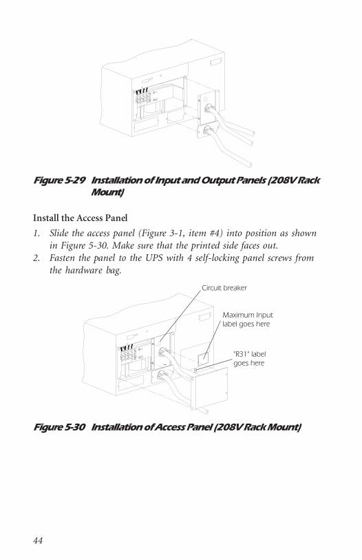
Figure 5-29 Installation of Input and Output Panels (208V RackMount)
Install the Access Panel
1. Slide the access panel (Figure 3-1, item #4) into position as shownin Figure 5-30. Make sure that the printed side faces out.
2. Fasten the panel to the UPS with 4 self-locking panel screws fromthe hardware bag.
Figure 5-30 Installation of Access Panel (208V Rack Mount)

45
5.4.5 Final Installation Procedure
A label must be applied to the chassis of the Smart-UPS unit to com-plete the installation.1. Retrieve both the receptacle option label sheet and the maximum
input label from the hardware bag.2. Remove the small “R31” label from the receptacle option label
sheet and apply it to the rear of the chassis, directly below the ex-isting model/serial number label. (See Figure 5-30)Note: Be careful not to cover any portion of the existing model/
serial number label.3. Apply the maximum input label adjacent to the existing label on
the rear of the chassis in the lower right corner.3. IMPORTANT: Make sure that all external wiring has been com-
pleted before turning on the UPS.

46
Limited WarrantyAmerican Power Conversion (APC) warrants its products to be freefrom defects in materials and workmanship for a period of two yearsfrom the date of purchase. Its obligation under this warranty is limitedto repairing or replacing, at its own sole option, any such defectiveproducts. To obtain service under warranty you must obtain a Re-turned Material Authorization (RMA) number from APC or an APCservice center. Products must be returned to APC or an APC servicecenter with transportation charges prepaid and must be accompaniedby a brief description of the problem encountered and proof of dateand place of purchase. This warranty does not apply to equipmentwhich has been damaged by accident, negligence, or misapplication orhas been altered or modified in any way. This warranty applies only tothe original purchaser who must have properly registered the productwithin 10 days of purchase.EXCEPT AS PROVIDED HEREIN, AMERICAN POWER CONVER-SION MAKES NO WARRANTIES, EXPRESS OR IMPLIED, INCLUD-ING WARRANTIES OF MERCHANTABILITY AND FITNESS FOR APARTICULAR PURPOSE. Some states do not permit limitation or ex-clusion of implied warranties; therefore, the aforesaid limitation(s) orexclusion(s) may not apply to the purchaser.EXCEPT AS PROVIDED ABOVE, IN NO EVENT WILL APC BE LI-ABLE FOR DIRECT, INDIRECT, SPECIAL, INCIDENTAL, OR CON-SEQUENTIAL DAMAGES ARISING OUT OF THE USE OF THISPRODUCT, EVEN IF ADVISED OF THE POSSIBILITY OF SUCHDAMAGE. Specifically, APC is not liable for any costs, such as lostprofits or revenue, loss of equipment, loss of use of equipment, loss ofsoftware, loss of data, costs of substitutes, claims by third parties, orotherwise. This warranty gives you specific legal rights and you mayalso have other rights which vary from state to state.

Customer ServiceNote: Before calling the Customer Service telephone number, pleasehave available the PDU’s model and serial numbers (see bar-coded la-bels).
Toll free technical support:United States and Canada 1-800-800-4272
Ireland 1-800-702000
U. K. 0800-132990
In areas without toll free numbers, call:+1 401 789 5735 (USA) or
+353 91 702020 (Ireland)
Return shipment addresses:American Power Conversion Corporation
132 Fairgrounds Road
P. O. Box 278
West Kingston, Rhode Island 02892
USA
American Power Conversion Corporation(A. P. C.) b. v.
Ballybritt Business Park
Galway
Ireland
Part Number 990-7033 Rev. 2 08/96